Instytut Fizyki Doświadczalnej Wydział Matematyki, Fizyki i Informatyki UNIWERSYTET GDAŃSKI
|
|
|
- Mae Cobb
- 5 years ago
- Views:
Transcription


1 Instytut Fizyki Doświadczalnej Wydział Matematyki, Fizyki i Informatyki UNIWERSYTET GDAŃSKI
 absorption of radiation; b) spontaneous emission; c) stimulated emission; d) dipole radiation and the")

 radiation transitions in semiconductors; b) conductivity of semiconductors; c) p n interface in semiconductor lasers (homo and")
 lasing threshold; b) types of cavities and their influence on resonance conditions; c) modal structure of laser")

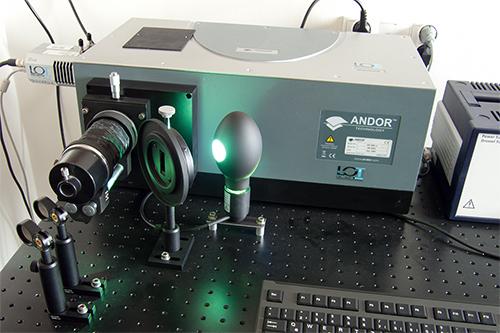
2 I. Background theory. 1. The temporal and spatial coherence of light. 2. Interaction of electromagnetic waves with a medium: a) absorption of radiation; b) spontaneous emission; c) stimulated emission; d) dipole radiation and the probability of absorption, spontaneous and forced emission; e) Einstein coefficients; f) lifetimes of excited states; g) spectral line profiles; Lorentz and Gaussian profiles. 3. Population inversion of atomic states. 4. Formation of energy bands in crystals. 5. Doped ions as luminescent centres in crystals. 6. Types of solid-state lasers. 7. Construction and operation of a triply ionised laser rare earth Nd: YAG laser. 8. Pumping of solid-state lasers. 9. Semiconductor lasers: a) radiation transitions in semiconductors; b) conductivity of semiconductors; c) p n interface in semiconductor lasers (homo and heterojunctions); d) radiation amplification in semiconductor lasers. 10. Absorption of radiation in Nd:YAG crystals. 11. The basic properties lasers and lasing: a) lasing threshold; b) types of cavities and their influence on resonance conditions; c) modal structure of laser radiation; d) performance curve of a laser; e) laser output power. II. Experimental tasks. 1. Familiarise yourself with the experimental setup shown in Pictures Measure the output power of a semiconductor laser as a function of current through the junction following steps II.3. II.12. Wear safety goggles when working with lasers. The continuous output power of the Nd:YAG laser exceeds 1mW and the laser light is very harmful to your eyes!!! Instytut Fizyki Doświadczalnej 1.

.")
; 3 collimator (ƒ = 6 mm); 4 lens (ƒ = 50 mm);")


.")


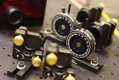
3 Experiment 23 : Studying the properties of solid-state lasers 3. Using scheme 1 in Figure 2, assemble the following elements on the optical bench: semiconductor laser (the left side of optical bench), a collimator (f = 6 mm) and a photodiode obscured by the visualisation screen (on the right end of the bench). Picture 1 Experimental setup to study the properties of a Nd:YAG laser: 1 laser diode power supply; 2 semiconducting laser (λ = 808,4 nm); 3 collimator (ƒ = 6 mm); 4 lens (ƒ = 50 mm); 5 Nd: YAG crystal; 6 KTP crystal; 7 mirror; 8 filter holder; 9 optical bench; 10 Si photodiode; 11 universal multimeter; 12 oscilloscope; 13 set of accessories (IR converter card; filters: BG39, RG1000, ND filter with optical density 1,1; photodiode cap). 4. Turn on the power to each component in your assembled setup. Check that the semiconductor laser 2, Picture 1 is connected to the power supply (connector 1 in Picture 4). Turn the temperature and current control knobs (5 and 6 in Picture 3) all the way to the left. Turn on the main power supply with its switch 6, Picture 4 (on the back of the housing). Turn key 1, Picture 3 to the ON position. An illuminated red LED on the laser means that you can adjust the temperature and current settings for the semiconductor laser junction. Figure 2. Various configurations of the Nd:YAG laser setup: 1 arrangement for measuring the semiconductor laser pump power; 2 focusing lens settings; 3 Nd:YAG crystal settings; 4 system to measure the absorption of the Nd: YAG crystal; 5 optical setup of the Nd:YAG laser; 6 optical setup of the Nd:YAG laser with frequency doubler. Instytut Fizyki Doświadczalnej 2.
 and continuous operation OFF respectively. Picture 3.")

4 Experiment 23 : Studying the properties of solid-state lasers 5. Set switches 2 and 3, Picture 3 to stabilised mode (Stab.) and continuous operation OFF respectively. Picture 3. View of the front panels of the LDC-01 laser power supply and DSO1002A oscilloscope: 1 laser power switch; 2 current stabiliser switch; 3 continuous/pulsed mode switch; 4 laser pulse frequency dial; 5, 6 p-n junction current and temperature controls. 6. Set the maximum current to 560 ma by turning dial 5, Picture 3 to the right. Picture 4. View of the rear panel of the laser power supply: 1 laser head power connector; 2 BNC photodiode input cable; 3 photodiode input gain dial; 4 BNC photodiode output signal; 5 BNC sync output; 6 main switch. Instytut Fizyki Doświadczalnej 3.
5 7. Set the collimator so as to obtain a parallel beam of light (1-2 mm from the laser). 8. Adjust the laser beam so that it shines on the centre of the visualisation screen. 9. Connect the photodiode to the preamplifier input 2, Picture 4. Set the gain dial 3, Picture 4 to position x Remove the screen in front of the photodiode and insert a grey filter with optical density at least 1 D. 11. Connect the amplifier output 4, Picture 4 with the universal multimeter 11, Picture 1 set to measure DC voltage. 12. Measure the laser output power P for two temperature 5 ⁰C and 45 ⁰C as a function of current I junction flowing through the semiconductor junction from 0 ma to 560 ma in steps of 25 ma. 13. Plot a graph of P = ƒ(i) for both temperatures T = 5 ⁰C and T = 45 ⁰C. Determine the threshold for stimulated emission generated by the semiconductor laser. 14. Measure the semiconductor laser output power as a function of temperature following steps II.15. II Use dial 5, Picture 3 to set a maximum current of 560 ma. 16. Set the gain dial 3, Picture 4 to position x Use dial 6, Picture 3 to adjust the temperature from 5 ⁰C to 45 ⁰C in steps of 2 ⁰C, each time noting the reading on the multimeter 11, Picture Turn the key 1, Picture 3 to the OFF position. 19. Use the plots in Figure 5 in Appendix A to convert voltage to power (taking into account the gain and attenuation filters). 20. Plot a graph of P = ƒ(t), I = const. 21. Measure the absorption of the neodymium-doped YAG crystal following steps II.22. to II Place the visualising screen in front of photodiode. 23. Place the focussing lens 4, Picture 1 behind the collimator on the optical bench. Slide it towards the collimator to the correct position such that the visualisation screen is illuminated as in scheme 2 in Figure Insert the Nd:YAG crystal 5, Picture 1 in the optical path, removing the visualisation screen the system should look like scheme 3, Figure Turn key 1, Picture 3 to the ON position, set the maximum current to 560 ma. 26. By gently moving the crystal, place it such that the multimeter indicates the maximum. 27. Set the gain dial 3, Picture 4 to position x Adjust the temperature from 5 ⁰C to 45 ⁰C in steps of 2 ⁰C while noting the voltage on the meter. 29. Plot a graph of A = ƒ(t), I = const. Determine the area of greatest absorption by the Nd 3+ ions. 30. Determine the Nd:YAG crystal luminescence decay profile following steps II.31 II Set the current to 560 ma by turning dial 5, Picture 3 to the right. 32. Use dial 6, Picture 3 to select the temperature for which the Nd:YAG crystal absorption is the highest. 33. Set switch 3, Picture 3 to the INT position. Instytut Fizyki Doświadczalnej 4.
6 34. Assemble the system according to scheme 4, Figure 2 by inserting the filter holder (8, Picture 1) with the FG 1000 filter and push the photodiode close to the filter. 35. Connect the photodiode signal to oscilloscope channel 1; Connect the sync output 5, Picture 4 to channel Save the observed waveforms to external USB memory as described in Appendix B. 37. Measure the Nd:YAG laser output power as a function of semiconductor laser power following steps II.38. II Set the current to 560 ma by turning dial 5, Picture 3 to the right. 39. Set switch 3, Picture 3 to the OFF position. 40. Assemble the system according to scheme 5 in Figure 2, inserting a filter with optical density at least 1 D just before the photodiode followed by filter RG 1000 (in holder 8, Picture 1) and the mirror (7, Picture 1) approximately 100 mm from the Nd:YAG crystal. 41. Connect the photodiode to the preamplifier input 2, Picture 4 and set the gain switch 3 to position x Change the position and orientation of mirrors 5 and 7 Picture 1 such that the signal on the meter is a maximum. 43. Use the graph in Figure 6 To plot the output power P YAG of the Nd:YAG laser as a function of power P of the semiconductor laser P YAG = ƒ(p), T const. 44. Measure the output power P SHG of the SHG laser (with frequency doubler) by inserting the frequency doubling KTP crystal (6, Picture 1) between the resonating mirrors as in scheme 6 in Figure Adjust the position and orientation of the KTP crystal in the cavity such that the signal on the meter is a maximum. 46. Use the graph in Figure 7 to plot P SHG = ƒ(p), T const. 47. Interpret the results from steps 13, 29, 30, 43, 46. III. Apparatus. 1. LDC-01 power supply for the semiconducting laser. 2. LDS 1200 semiconducting laser. 3. Collimator with focal length 6 mm. 4. Lens with focal length 50 mm. 5. Nd:YAG crystal with AR-coating mirror in XY bracket. 6. KTP crystal generating second harmonics mounted in XY bracket. 7. Mirror mounted in XY bracket. 8. Filter holders. 9. Optical bench. 10. Detector semiconductor diode with visualisation screen. 11. Universal multimeter. 12. Dual-channel oscilloscope model DSO 1002 A ( Agilent Technology) 13. Set of accessories: IR converter screen, bandpass filters 532 nm (BG39) and 1064 nm (RG 1000), ND filter with optical density 1,1D, visualisation screen mounted on photodiode. Instytut Fizyki Doświadczalnej 5.
7 IV. Literature. 1. N.W. Ashcroft, N.D. Mermin Solid State Physics, Saunders College, Philadelphia K. Shimoda Introduction to Laser Physics, Springer, W.W. Chow, S.W. Koch, M. Sargent Semiconductor Laser Physics, Springer, Berlin W. Demtröder Laser Spectroscopy. Basic Concepts and Instrumentation, Springer, H. Abramczyk Introduction to Laser Spectroscopy, Elsevier Science, Amsterdam W. Demtröder Atoms, Molecules and Photons: an Introduction to Atomic-, Molecular- and Quantum-Physics, Springer, Berlin Instytut Fizyki Doświadczalnej 6.
8 Appendix A Dependence of the laser power on the photodiode signal. Laser power as a function of voltage at the Si photodiode 300 λ=808,4 nm Y = -3, ,56*X P (mw) U (V) Figure 5. Scaled plot of semiconductor laser with wavelength λ = 808,4 nm output power as a function of photodiode voltage. Laser power as a function of voltage at the Si photodiode 100 λ=1064 nm Y = -1, ,73*X 80 P (mw) U (V) Figure 6. Scaled plot of Nd:YAG laser with wavelength λ = 1064 nm output power as a function of photodiode voltage. Instytut Fizyki Doświadczalnej 7.
9 Laser power as a function of voltage at the Si photodiode 0,4 λ=535 nm Y = -0, ,68*X 0,3 P (mw) 0,2 0,1 0,010 0,015 0,020 U (V) Figure 7. Scaled plot of SHG laser with wavelength λ=535 nm output power as a function of photodiode voltage. Instytut Fizyki Doświadczalnej 8.
 which allows you to connect it to external storage or a printer.")
. Picture 8. Oscilloscope front panel: 1 USB slot; 2")
10 Experiment 23 : Studying the properties of solid-state lasers Appendix B Reading and saving signals with the DSO 1002 A oscilloscope (Agilent Technology) The oscilloscope has internal non-volatile memory and a USB input (1 in Picture 8) which allows you to connect it to external storage or a printer. You can save/read data to/from one of the ten internal memory slots or to external storage with the following steps: 1. Saving to external media requires plugging the external memory into the USB port (1 in Picture 8). Picture 8. Oscilloscope front panel: 1 USB slot; 2 save/read data button. 2. Press Save/Recall (2 in Picture 8) on the oscilloscope front panel. 3. Select the internal data format Waveform or ASCII (CSV) (1 in Picture 9) by pressing Storage or turning the dial. Picture 9. Write/read menu on the oscilloscope front panel: 1 data type selection button; 2 memory manager button. Instytut Fizyki Doświadczalnej 9.
11 To write or read data to or from internal memory: a. Select Internal. b. Press Location in the menu Internal. c. Press Location or turn the dial, to select an internal memory storage location. N indicates that the slot is empty while S indicates that a waveform is stored in this slot. Press Save or Load. To write or read data to or from external memory: a. Select External. b. Use the Disk Manager to choose a folder in which to save the file 2, Picture 9. c. Select New File from the External menu, enter the filename and choose Save. To read data, select Load (it will read files with the extension.wfm). d. Press Location or turn the dial to select an external memory storage location. N indicates that the slot is empty while S indicates that a waveform is stored in this slot. e. Press Save or Load. Instytut Fizyki Doświadczalnej 10.
Instytut Fizyki Doświadczalnej Wydział Matematyki, Fizyki i Informatyki UNIWERSYTET GDAŃSKI
 Instytut Fizyki Doświadczalnej Wydział Matematyki, Fizyki i Informatyki UNIWERSYTET GDAŃSKI I. Background theory. 1. Electron energy levels in atoms. 2. Quantum numbers of electron energy levels. 3. Magnetic
SECOND HARMONIC GENERATION AND Q-SWITCHING
 SECOND HARMONIC GENERATION AND Q-SWITCHING INTRODUCTION In this experiment, the following learning subjects will be worked out: 1) Characteristics of a semiconductor diode laser. 2) Optical pumping on
LEP Optical pumping
 Related topics Spontaeous emission, induced emission, mean lifetime of a metastable state, relaxation, inversion, diode laser. Principle and task The visible light of a semiconductor diode laser is used
Spectroscopy of Ruby Fluorescence Physics Advanced Physics Lab - Summer 2018 Don Heiman, Northeastern University, 1/12/2018
 1 Spectroscopy of Ruby Fluorescence Physics 3600 - Advanced Physics Lab - Summer 2018 Don Heiman, Northeastern University, 1/12/2018 I. INTRODUCTION The laser was invented in May 1960 by Theodor Maiman.
Measuring Kinetics of Luminescence with TDS 744 oscilloscope
 Measuring Kinetics of Luminescence with TDS 744 oscilloscope Eex Nex Luminescence Photon E 0 Disclaimer Safety the first!!! This presentation is not manual. It is just brief set of rule to remind procedure
DEVELOPMENT OF CW AND Q-SWITCHED DIODE PUMPED ND: YVO 4 LASER
 DEVELOPMENT OF CW AND Q-SWITCHED DIODE PUMPED ND: YVO 4 LASER Gagan Thakkar 1, Vatsal Rustagi 2 1 Applied Physics, 2 Production and Industrial Engineering, Delhi Technological University, New Delhi (India)
Ba 14: Solid State Laser Principles I
 - Ba 14.1 - Ba 14: Solid State Laser Principles I 1. Abstract The process of light amplification by stimulated emission of radiation (laser) can currently provide electromagnetic radiation with exceptional
Solid-State Laser Engineering
 Walter Koechner Solid-State Laser Engineering Fourth Extensively Revised and Updated Edition With 449 Figures Springer Contents 1. Introduction 1 1.1 Optical Amplification 1 1.2 Interaction of Radiation
Ph 77 ADVANCED PHYSICS LABORATORY ATOMIC AND OPTICAL PHYSICS
 Ph 77 ADVANCED PHYSICS LABORATORY ATOMIC AND OPTICAL PHYSICS Diode Laser Characteristics I. BACKGROUND Beginning in the mid 1960 s, before the development of semiconductor diode lasers, physicists mostly
Optical Gain Experiment Manual
 Optical Gain Experiment Manual Table of Contents Purpose 1 Scope 1 1. Background Theory 1 1.1 Absorption, Spontaneous Emission and Stimulated Emission... 2 1.2 Direct and Indirect Semiconductors... 3 1.3
COMPONENTS OF OPTICAL INSTRUMENTS. Chapter 7 UV, Visible and IR Instruments
 COMPONENTS OF OPTICAL INSTRUMENTS Chapter 7 UV, Visible and IR Instruments 1 Topics A. GENERAL DESIGNS B. SOURCES C. WAVELENGTH SELECTORS D. SAMPLE CONTAINERS E. RADIATION TRANSDUCERS F. SIGNAL PROCESSORS
COMPONENTS OF OPTICAL INSTRUMENTS. Topics
 COMPONENTS OF OPTICAL INSTRUMENTS Chapter 7 UV, Visible and IR Instruments Topics A. GENERAL DESIGNS B. SOURCES C. WAVELENGTH SELECTORS D. SAMPLE CONTAINERS E. RADIATION TRANSDUCERS F. SIGNAL PROCESSORS
Luminous Equivalent of Radiation
 Intensity vs λ Luminous Equivalent of Radiation When the spectral power (p(λ) for GaP-ZnO diode has a peak at 0.69µm) is combined with the eye-sensitivity curve a peak response at 0.65µm is obtained with
Exp. No. 13 Measuring the runtime of light in the fiber
 Exp. No. 13 Measuring the runtime of light in the fiber Aim of Experiment The aim of experiment is measuring the runtime of light in optical fiber with length of 1 km and the refractive index of optical
PCS-150 / PCI-200 High Speed Boxcar Modules
 Becker & Hickl GmbH Kolonnenstr. 29 10829 Berlin Tel. 030 / 787 56 32 Fax. 030 / 787 57 34 email: info@becker-hickl.de http://www.becker-hickl.de PCSAPP.DOC PCS-150 / PCI-200 High Speed Boxcar Modules
Optodevice Data Book ODE I. Rev.9 Mar Opnext Japan, Inc.
 Optodevice Data Book ODE-408-001I Rev.9 Mar. 2003 Opnext Japan, Inc. Section 1 Operating Principles 1.1 Operating Principles of Laser Diodes (LDs) and Infrared Emitting Diodes (IREDs) 1.1.1 Emitting Principles
Nd: YAG Laser Energy Levels 4 level laser Optical transitions from Ground to many upper levels Strong absorber in the yellow range None radiative to
 Nd: YAG Lasers Dope Neodynmium (Nd) into material (~1%) Most common Yttrium Aluminum Garnet - YAG: Y 3 Al 5 O 12 Hard brittle but good heat flow for cooling Next common is Yttrium Lithium Fluoride: YLF
Vertical External Cavity Surface Emitting Laser
 Chapter 4 Optical-pumped Vertical External Cavity Surface Emitting Laser The booming laser techniques named VECSEL combine the flexibility of semiconductor band structure and advantages of solid-state
LABORATORY INSTRUCTION NOTES ERBIUM-DOPED FIBER AMPLIFIER
 ECE1640H Advanced Labs for Special Topics in Photonics LABORATORY INSTRUCTION NOTES ERBIUM-DOPED FIBER AMPLIFIER Fictitious moving pill box in a fiber amplifier Faculty of Applied Science and Engineering
Experimental Physics. Experiment C & D: Pulsed Laser & Dye Laser. Course: FY12. Project: The Pulsed Laser. Done by: Wael Al-Assadi & Irvin Mangwiza
 Experiment C & D: Course: FY1 The Pulsed Laser Done by: Wael Al-Assadi Mangwiza 8/1/ Wael Al Assadi Mangwiza Experiment C & D : Introduction: Course: FY1 Rev. 35. Page: of 16 1// In this experiment we
Basic concepts. Optical Sources (b) Optical Sources (a) Requirements for light sources (b) Requirements for light sources (a)
 Optical Sources (a) Requirements for light sources (b) Requirements for light sources (a)") Optical Sources (a) Optical Sources (b) The main light sources used with fibre optic systems are: Light-emitting diodes (LEDs) Semiconductor lasers (diode lasers) Fibre laser and other compact solid-state
Optical Sources (a) Optical Sources (b) The main light sources used with fibre optic systems are: Light-emitting diodes (LEDs) Semiconductor lasers (diode lasers) Fibre laser and other compact solid-state
Lecture 5: Introduction to Lasers
 Lecture 5: Introduction to Lasers http://en.wikipedia.org/wiki/laser History of the Laser v Invented in 1958 by Charles Townes (Nobel prize in Physics 1964) and Arthur Schawlow of Bell Laboratories v Was
Diode Pumped Nd:YAG Laser
 ALKAAD Photonics Teaching and Operation Manual Diode Pumped Nd:YAG Laser Compiled by Akanksha Goyal and Mukul Goyal New Delhi - December 8, 2014 www. alkaad.com 2 Contents 1 Introduction 1 2 Neodymium
1. INTRODUCTION 2. LASER ABSTRACT
 Compact solid-state laser to generate 5 mj at 532 nm Bhabana Pati*, James Burgess, Michael Rayno and Kenneth Stebbins Q-Peak, Inc., 135 South Road, Bedford, Massachusetts 01730 ABSTRACT A compact and simple
DIODE LASER SPECTROSCOPY (160309)
") DIODE LASER SPECTROSCOPY (160309) Introduction The purpose of this laboratory exercise is to illustrate how we may investigate tiny energy splittings in an atomic system using laser spectroscopy. As an
DIODE LASER SPECTROSCOPY (160309) Introduction The purpose of this laboratory exercise is to illustrate how we may investigate tiny energy splittings in an atomic system using laser spectroscopy. As an
Optical Fiber Amplifiers. Scott Freese. Physics May 2008
 Optical Fiber Amplifiers Scott Freese Physics 262 2 May 2008 Partner: Jared Maxson Abstract The primary goal of this experiment was to gain an understanding of the basic components of an Erbium doped fiber
ECE 340 Lecture 29 : LEDs and Lasers Class Outline:
 ECE 340 Lecture 29 : LEDs and Lasers Class Outline: Light Emitting Diodes Lasers Semiconductor Lasers Things you should know when you leave Key Questions What is an LED and how does it work? How does a
Examination Optoelectronic Communication Technology. April 11, Name: Student ID number: OCT1 1: OCT 2: OCT 3: OCT 4: Total: Grade:
 Examination Optoelectronic Communication Technology April, 26 Name: Student ID number: OCT : OCT 2: OCT 3: OCT 4: Total: Grade: Declaration of Consent I hereby agree to have my exam results published on
Key Questions. What is an LED and how does it work? How does a laser work? How does a semiconductor laser work? ECE 340 Lecture 29 : LEDs and Lasers
 Things you should know when you leave Key Questions ECE 340 Lecture 29 : LEDs and Class Outline: What is an LED and how does it How does a laser How does a semiconductor laser How do light emitting diodes
Introduction Fundamentals of laser Types of lasers Semiconductor lasers
 ECE 5368 Introduction Fundamentals of laser Types of lasers Semiconductor lasers Introduction Fundamentals of laser Types of lasers Semiconductor lasers How many types of lasers? Many many depending on
Absorption: in an OF, the loss of Optical power, resulting from conversion of that power into heat.
 Absorption: in an OF, the loss of Optical power, resulting from conversion of that power into heat. Scattering: The changes in direction of light confined within an OF, occurring due to imperfection in
High power VCSEL array pumped Q-switched Nd:YAG lasers
 High power array pumped Q-switched Nd:YAG lasers Yihan Xiong, Robert Van Leeuwen, Laurence S. Watkins, Jean-Francois Seurin, Guoyang Xu, Alexander Miglo, Qing Wang, and Chuni Ghosh Princeton Optronics,
Photon Counters SR430 5 ns multichannel scaler/averager
 Photon Counters SR430 5 ns multichannel scaler/averager SR430 Multichannel Scaler/Averager 5 ns to 10 ms bin width Count rates up to 100 MHz 1k to 32k bins per record Built-in discriminator No interchannel
FPPO 1000 Fiber Laser Pumped Optical Parametric Oscillator: FPPO 1000 Product Manual
 Fiber Laser Pumped Optical Parametric Oscillator: FPPO 1000 Product Manual 2012 858 West Park Street, Eugene, OR 97401 www.mtinstruments.com Table of Contents Specifications and Overview... 1 General Layout...
Lecture 6 Fiber Optical Communication Lecture 6, Slide 1
 Lecture 6 Optical transmitters Photon processes in light matter interaction Lasers Lasing conditions The rate equations CW operation Modulation response Noise Light emitting diodes (LED) Power Modulation
FIBER OPTICS. Prof. R.K. Shevgaonkar. Department of Electrical Engineering. Indian Institute of Technology, Bombay. Lecture: 18.
 FIBER OPTICS Prof. R.K. Shevgaonkar Department of Electrical Engineering Indian Institute of Technology, Bombay Lecture: 18 Optical Sources- Introduction to LASER Diodes Fiber Optics, Prof. R.K. Shevgaonkar,
Lasers PH 645/ OSE 645/ EE 613 Summer 2010 Section 1: T/Th 2:45-4:45 PM Engineering Building 240
 Lasers PH 645/ OSE 645/ EE 613 Summer 2010 Section 1: T/Th 2:45-4:45 PM Engineering Building 240 John D. Williams, Ph.D. Department of Electrical and Computer Engineering 406 Optics Building - UAHuntsville,
High Average Power, High Repetition Rate Side-Pumped Nd:YVO 4 Slab Laser
 High Average Power, High Repetition Rate Side-Pumped Nd:YVO Slab Laser Kevin J. Snell and Dicky Lee Q-Peak Incorporated 135 South Rd., Bedford, MA 173 (71) 75-9535 FAX (71) 75-97 e-mail: ksnell@qpeak.com,
St. Joseph s College of Arts & Science (Autonomous) Cuddalore PG & RESEARCH DEPARTMENT OF PHYSICS SUBJECT : LASER & FIBER OPTICCOMMUNICATION
 Cuddalore PG & RESEARCH DEPARTMENT OF PHYSICS SUBJECT : LASER & FIBER OPTICCOMMUNICATION") St. Joseph s College of Arts & Science (Autonomous) Cuddalore 607001 PG & RESEARCH DEPARTMENT OF PHYSICS SUBJECT : LASER & FIBER OPTICCOMMUNICATION SUBJECT CODE: PH612S SUBJECT INCHARGE: Mr. M.Sathish
St. Joseph s College of Arts & Science (Autonomous) Cuddalore 607001 PG & RESEARCH DEPARTMENT OF PHYSICS SUBJECT : LASER & FIBER OPTICCOMMUNICATION SUBJECT CODE: PH612S SUBJECT INCHARGE: Mr. M.Sathish
EXPERIMENT 3 THE PHOTOELECTRIC EFFECT
 EXPERIMENT 3 THE PHOTOELECTRIC EFFECT Equipment List Included Equipment 1. Mercury Light Source Enclosure 2. Track, 60 cm 3. Photodiode Enclosure 4. Mercury Light Source Power Supply 5. DC Current Amplifier
Fundamentals of Laser
 SMR 1826-3 Preparatory School to the Winter College on Fibre 5-9 February 2007 Fundamentals of Laser Imrana Ashraf Zahid Quaid-i-Azam University Islamabad Pakistan Fundamentals of Laser Dr. Imrana Ashraf
BN 1000 May Profile Optische Systeme GmbH Gauss Str. 11 D Karlsfeld / Germany. Tel Fax
 BN 1000 May 2000 Profile Optische Systeme GmbH Gauss Str. 11 D - 85757 Karlsfeld / Germany Tel + 49 8131 5956-0 Fax + 49 8131 5956-99 info@profile-optsys.com www.profile-optsys.com Profile Inc. 87 Hibernia
Chapter 3 OPTICAL SOURCES AND DETECTORS
 Chapter 3 OPTICAL SOURCES AND DETECTORS 3. Optical sources and Detectors 3.1 Introduction: The success of light wave communications and optical fiber sensors is due to the result of two technological breakthroughs.
Laser Locking with Doppler-free Saturated Absorption Spectroscopy
 Laser Locking with Doppler-free Saturated Absorption Spectroscopy Paul L. Stubbs, Advisor: Irina Novikova W&M Quantum Optics Group May 12, 2010 Abstract The goal of this project was to lock the frequency
Functional Materials. Optoelectronic devices
 Functional Materials Lecture 2: Optoelectronic materials and devices (inorganic). Photonic materials Optoelectronic devices Light-emitting diode (LED) displays Photodiode and Solar cell Photoconductive
Single frequency MOPA system with near diffraction limited beam
 Single frequency MOPA system with near diffraction limited beam quality D. Chuchumishev, A. Gaydardzhiev, A. Trifonov, I. Buchvarov Abstract Near diffraction limited pulses of a single-frequency and passively
High-Power, Passively Q-switched Microlaser - Power Amplifier System
 High-Power, Passively Q-switched Microlaser - Power Amplifier System Yelena Isyanova Q-Peak, Inc.,135 South Road, Bedford, MA 01730 isyanova@qpeak.com Jeff G. Manni JGM Associates, 6 New England Executive
Quantum-Well Semiconductor Saturable Absorber Mirror
 Chapter 3 Quantum-Well Semiconductor Saturable Absorber Mirror The shallow modulation depth of quantum-dot saturable absorber is unfavorable to increasing pulse energy and peak power of Q-switched laser.
Advanced Optical Communications Prof. R. K. Shevgaonkar Department of Electrical Engineering Indian Institute of Technology, Bombay
 Advanced Optical Communications Prof. R. K. Shevgaonkar Department of Electrical Engineering Indian Institute of Technology, Bombay Lecture No. # 27 EDFA In the last lecture, we talked about wavelength
Cavity QED with quantum dots in semiconductor microcavities
 Cavity QED with quantum dots in semiconductor microcavities M. T. Rakher*, S. Strauf, Y. Choi, N.G. Stolz, K.J. Hennessey, H. Kim, A. Badolato, L.A. Coldren, E.L. Hu, P.M. Petroff, D. Bouwmeester University
Nd:YSO resonator array Transmission spectrum (a. u.) Supplementary Figure 1. An array of nano-beam resonators fabricated in Nd:YSO.
 Supplementary Figure 1. An array of nano-beam resonators fabricated in Nd:YSO.") a Nd:YSO resonator array µm Transmission spectrum (a. u.) b 4 F3/2-4I9/2 25 2 5 5 875 88 λ(nm) 885 Supplementary Figure. An array of nano-beam resonators fabricated in Nd:YSO. (a) Scanning electron microscope
a Nd:YSO resonator array µm Transmission spectrum (a. u.) b 4 F3/2-4I9/2 25 2 5 5 875 88 λ(nm) 885 Supplementary Figure. An array of nano-beam resonators fabricated in Nd:YSO. (a) Scanning electron microscope
Microscopy. The dichroic mirror is an important component of the fluorescent scope: it reflects blue light while transmitting green light.
 Microscopy I. Before coming to lab Read this handout and the background. II. Learning Objectives In this lab, you'll investigate the physics of microscopes. The main idea is to understand the limitations
Index Terms WDM, multi-wavelength Erbium Doped fiber laser.
 A Multi-wavelength Erbium Doped Fiber Laser for Free Space Optical Communication link S. Qhumayo, R. Martinez Manuel and J.J. M. Kaboko Photonics Research Group, Department of Electrical and Electronic
The 34th International Physics Olympiad
 The 34th International Physics Olympiad Taipei, Taiwan Experimental Competition Wednesday, August 6, 2003 Time Available : 5 hours Please Read This First: 1. Use only the pen provided. 2. Use only the
Class Room Experiments on Laser Physics. Alika Khare
 Ref ETOP : ETOP004 Class Room Experiments on Laser Physics Alika Khare Department of Physics Indian Institute of Technology, Guwahati, Guwahati, 781039, India email: alika@iitg.ernet.in Abstract Lasers
High energy khz Mid-IR tunable PPSLT OPO pumped at 1064 nm
 High energy khz Mid-IR tunable PPSLT OPO pumped at 1064 nm A. Gaydardzhiev, D. Chuchumishev, D. Draganov, I. Buchvarov Abstract We report a single frequency sub-nanosecond optical parametric oscillator
Typical LED Characteristics
 Typical LED Characteristics Characteristic Unit Value Light output 1 mw > 1 2 Peak wavelength 3 nm 255 nm to 28 nm 4 Viewing angle Degrees 11 5 Full width at half maximum 3 (@1 ma) nm 16 Forward voltage
Photonics and Fiber Optics
 1 UNIT V Photonics and Fiber Optics Part-A 1. What is laser? LASER is the acronym for Light Amplification by Stimulated Emission of Radiation. The absorption and emission of light by materials has been
Instruction manual and data sheet ipca h
 1/15 instruction manual ipca-21-05-1000-800-h Instruction manual and data sheet ipca-21-05-1000-800-h Broad area interdigital photoconductive THz antenna with microlens array and hyperhemispherical silicon
Introduction Fundamental of optical amplifiers Types of optical amplifiers
 ECE 6323 Introduction Fundamental of optical amplifiers Types of optical amplifiers Erbium-doped fiber amplifiers Semiconductor optical amplifier Others: stimulated Raman, optical parametric Advanced application:
362 Part 5 Appendices
 Part 5 Appendices 362 Appendix A Classification of Laser System Performance 363 This appendix contains a description of the methods used to classify the performance of the lasers used in the infrared cavity
R. J. Jones Optical Sciences OPTI 511L Fall 2017
 R. J. Jones Optical Sciences OPTI 511L Fall 2017 Semiconductor Lasers (2 weeks) Semiconductor (diode) lasers are by far the most widely used lasers today. Their small size and properties of the light output
MASSACHUSETTS INSTITUTE OF TECHNOLOGY Department of Electrical Engineering and Computer Science
 Student Name Date MASSACHUSETTS INSTITUTE OF TECHNOLOGY Department of Electrical Engineering and Computer Science 6.161 Modern Optics Project Laboratory Laboratory Exercise No. 6 Fall 2010 Solid-State
PoS(PhotoDet 2012)051
051") Optical to electrical detection delay in avalanche photodiode based detector and its interpretation Josef Blažej 1 E-mail: blazej@fjfi.cvut.cz Ivan Procházka Jan Kodet Technical University in Munich FSG,
Optical to electrical detection delay in avalanche photodiode based detector and its interpretation Josef Blažej 1 E-mail: blazej@fjfi.cvut.cz Ivan Procházka Jan Kodet Technical University in Munich FSG,
Review of Semiconductor Physics
 Review of Semiconductor Physics k B 1.38 u 10 23 JK -1 a) Energy level diagrams showing the excitation of an electron from the valence band to the conduction band. The resultant free electron can freely
Wavelength Control and Locking with Sub-MHz Precision
 Wavelength Control and Locking with Sub-MHz Precision A PZT actuator on one of the resonator mirrors enables the Verdi output wavelength to be rapidly tuned over a range of several GHz or tightly locked
The Effect of He-Ne and Diode Lasers on the Electrical Characteristics of Silicon Diode
 American Journal of Optics and Photonics 2018; 6(1): 8-13 http://www.sciencepublishinggroup.com/j/ajop doi: 10.11648/j.ajop.20180601.12 ISSN: 2330-8486 (Print); ISSN: 2330-8494 (Online) The Effect of He-Ne
The Report of Gain Performance Characteristics of the Erbium Doped Fiber Amplifier (EDFA)
") The Report of Gain Performance Characteristics of the Erbium Doped Fiber Amplifier (EDFA) Masruri Masruri (186520) 22/05/2008 1 Laboratory Setup The laboratory setup using in this laboratory experiment
The Report of Gain Performance Characteristics of the Erbium Doped Fiber Amplifier (EDFA) Masruri Masruri (186520) 22/05/2008 1 Laboratory Setup The laboratory setup using in this laboratory experiment
S Optical Networks Course Lecture 2: Essential Building Blocks
 S-72.3340 Optical Networks Course Lecture 2: Essential Building Blocks Edward Mutafungwa Communications Laboratory, Helsinki University of Technology, P. O. Box 2300, FIN-02015 TKK, Finland Tel: +358 9
Semiconductor Optical Communication Components and Devices Lecture 18: Introduction to Diode Lasers - I
 Semiconductor Optical Communication Components and Devices Lecture 18: Introduction to Diode Lasers - I Prof. Utpal Das Professor, Department of lectrical ngineering, Laser Technology Program, Indian Institute
External cavities for controling spatial and spectral properties of SC lasers. J.P. Huignard TH-TRT
 External cavities for controling spatial and spectral properties of SC lasers. J.P. Huignard TH-TRT Bright Er - Partners. WP 3 : External cavities approaches for high brightness. - RISOE TUD Dk - Institut
Class #9: Experiment Diodes Part II: LEDs
 Class #9: Experiment Diodes Part II: LEDs Purpose: The objective of this experiment is to become familiar with the properties and uses of LEDs, particularly as a communication device. This is a continuation
A Narrow-Band Tunable Diode Laser System with Grating Feedback
 A Narrow-Band Tunable Diode Laser System with Grating Feedback S.P. Spirydovich Draft Abstract The description of diode laser was presented. The tuning laser system was built and aligned. The free run
Temporal coherence characteristics of a superluminescent diode system with an optical feedback mechanism
 VI Temporal coherence characteristics of a superluminescent diode system with an optical feedback mechanism Fang-Wen Sheu and Pei-Ling Luo Department of Applied Physics, National Chiayi University, Chiayi
Laser Beam Analysis Using Image Processing
 Journal of Computer Science 2 (): 09-3, 2006 ISSN 549-3636 Science Publications, 2006 Laser Beam Analysis Using Image Processing Yas A. Alsultanny Computer Science Department, Amman Arab University for
Fiberoptic Communication Systems By Dr. M H Zaidi. Optical Amplifiers
 Optical Amplifiers Optical Amplifiers Optical signal propagating in fiber suffers attenuation Optical power level of a signal must be periodically conditioned Optical amplifiers are a key component in
Measurement of the Speed of Light in Air
 (revised, 2/27/01) Measurement of the Speed of Light in Air Advanced Laboratory, Physics 407 University of Wisconsin Madison, WI 53706 Abstract The speed of light is determined from a time of flight measurement
Grating-Stabilized Diode Laser (for 1064nm)
") Grating-Stabilized Diode Laser (for 1064nm), July 2011 This documentation describes the assembly of a tunable laser under the Littrow configuration, using a diffraction grating as the wavelength-selective
Grating-Stabilized Diode Laser (for 1064nm), July 2011 This documentation describes the assembly of a tunable laser under the Littrow configuration, using a diffraction grating as the wavelength-selective
For more information, please contact
 Solar Powered Laser Design Team Timothy Forrest, Joshua Hecht Dalyssa Hernandez, Adam Khaw, Brian Racca Design Advisor Prof. Greg Kowalski Abstract The purpose of this project is to develop a device that
Speed of Light in Air
 Speed of Light in Air Introduction Light can travel a distance comparable to seven and one-half times around the Earth in one second. The first accurate measurements of the speed of light were performed
Generation of 11.5 W coherent red-light by intra-cavity frequency-doubling of a side-pumped Nd:YAG laser in a 4-cm LBO
 Optics Communications 241 (2004) 167 172 www.elsevier.com/locate/optcom Generation of 11.5 W coherent red-light by intra-cavity frequency-doubling of a side-pumped Nd:YAG laser in a 4-cm LBO Zhipei Sun
LASER DIODE MODULATION AND NOISE
 > 5' O ft I o Vi LASER DIODE MODULATION AND NOISE K. Petermann lnstitutfiir Hochfrequenztechnik, Technische Universitdt Berlin Kluwer Academic Publishers i Dordrecht / Boston / London KTK Scientific Publishers
Mitigation of Self-Pulsing in High Power Pulsed Fiber Lasers
 Mitigation of Self-Pulsing in High Power Pulsed Fiber Lasers Yusuf Panbiharwala, Deepa Venkitesh, Balaji Srinivasan* Department of Electrical Engineering, Indian Institute of Technology Madras. *Email
Spectroscopy Lab 2. Reading Your text books. Look under spectra, spectrometer, diffraction.
 1 Spectroscopy Lab 2 Reading Your text books. Look under spectra, spectrometer, diffraction. Consult Sargent Welch Spectrum Charts on wall of lab. Note that only the most prominent wavelengths are displayed
FIBER OPTICS. Prof. R.K. Shevgaonkar. Department of Electrical Engineering. Indian Institute of Technology, Bombay. Lecture: 37
 FIBER OPTICS Prof. R.K. Shevgaonkar Department of Electrical Engineering Indian Institute of Technology, Bombay Lecture: 37 Introduction to Raman Amplifiers Fiber Optics, Prof. R.K. Shevgaonkar, Dept.
MASSACHUSETTS INSTITUTE OF TECHNOLOGY Department of Electrical Engineering and Computer Science
 Student Name Date MASSACHUSETTS INSTITUTE OF TECHNOLOGY Department of Electrical Engineering and Computer Science 6.161 Modern Optics Project Laboratory Laboratory Exercise No. 7 Fall 2016 Solid-State
Lecture 4 INTEGRATED PHOTONICS
 Lecture 4 INTEGRATED PHOTONICS What is photonics? Photonic applications use the photon in the same way that electronic applications use the electron. Devices that run on light have a number of advantages
Ma 14: Solid State Laser Principles II
 - Ma 14.1 - Ma 14: Solid State Laser Principles II 1. Abstract The process of light amplification by stimulated emission of radiation (laser) can currently provide electromagnetic radiation with exceptional
Optical Amplifiers Photonics and Integrated Optics (ELEC-E3240) Zhipei Sun Photonics Group Department of Micro- and Nanosciences Aalto University
 Zhipei Sun Photonics Group Department of Micro- and Nanosciences Aalto University") Photonics Group Department of Micro- and Nanosciences Aalto University Optical Amplifiers Photonics and Integrated Optics (ELEC-E3240) Zhipei Sun Last Lecture Topics Course introduction Ray optics & optical
Photonics Group Department of Micro- and Nanosciences Aalto University Optical Amplifiers Photonics and Integrated Optics (ELEC-E3240) Zhipei Sun Last Lecture Topics Course introduction Ray optics & optical
Chapter 8. Wavelength-Division Multiplexing (WDM) Part II: Amplifiers
 Part II: Amplifiers") Chapter 8 Wavelength-Division Multiplexing (WDM) Part II: Amplifiers Introduction Traditionally, when setting up an optical link, one formulates a power budget and adds repeaters when the path loss exceeds
Chapter 8 Wavelength-Division Multiplexing (WDM) Part II: Amplifiers Introduction Traditionally, when setting up an optical link, one formulates a power budget and adds repeaters when the path loss exceeds
A continuous-wave Raman silicon laser
 A continuous-wave Raman silicon laser Haisheng Rong, Richard Jones,.. - Intel Corporation Ultrafast Terahertz nanoelectronics Lab Jae-seok Kim 1 Contents 1. Abstract 2. Background I. Raman scattering II.
Optical Sources and Detectors
 Optical Sources and Detectors 1. Optical Sources Optical transmitter coverts electrical input signal into corresponding optical signal. The optical signal is then launched into the fiber. Optical source
High-Power Semiconductor Laser Amplifier for Free-Space Communication Systems
 64 Annual report 1998, Dept. of Optoelectronics, University of Ulm High-Power Semiconductor Laser Amplifier for Free-Space Communication Systems G. Jost High-power semiconductor laser amplifiers are interesting
3.003 Lab 3 Part A. Measurement of Speed of Light
 3.003 Lab 3 Part A. Measurement of Speed of Light Objective: To measure the speed of light in free space Experimental Apparatus: Feb. 18, 2010 Due Mar. 2, 2010 Components: 1 Laser, 4 mirrors, 1 beam splitter
CONTENTS. Chapter 1 Wave Nature of Light 19
 CONTENTS Chapter 1 Wave Nature of Light 19 1.1 Light Waves in a Homogeneous Medium 19 A. Plane Electromagnetic Wave 19 B. Maxwell's Wave Equation and Diverging Waves 22 Example 1.1.1 A diverging laser
Picosecond laser system based on microchip oscillator
 JOURNAL OF OPTOELECTRONICS AND ADVANCED MATERIALS Vol. 10, No. 11, November 008, p. 30-308 Picosecond laser system based on microchip oscillator A. STRATAN, L. RUSEN *, R. DABU, C. FENIC, C. BLANARU Department
Doppler-Free Spetroscopy of Rubidium
 Doppler-Free Spetroscopy of Rubidium Pranjal Vachaspati, Sabrina Pasterski MIT Department of Physics (Dated: April 17, 2013) We present a technique for spectroscopy of rubidium that eliminates doppler
Elements of Optical Networking
 Bruckner Elements of Optical Networking Basics and practice of optical data communication With 217 Figures, 13 Tables and 93 Exercises Translated by Patricia Joliet VIEWEG+ TEUBNER VII Content Preface
Design Coordination of Pre-amp EDFAs and PIN Photon Detectors For Use in Telecommunications Optical Receivers
 Paper 010, ENT 201 Design Coordination of Pre-amp EDFAs and PIN Photon Detectors For Use in Telecommunications Optical Receivers Akram Abu-aisheh, Hisham Alnajjar University of Hartford abuaisheh@hartford.edu,