Thyristor power controller B DI1002 V1.0 Manual/Operating instructions
|
|
|
- Charleen Floyd
- 5 years ago
- Views:
Transcription

1 1 B DI1002 V1.0 Manual/Operating instructions
2 2 1 Introduction Before you put the thyristor controller into operation, please read these operating instructions. Keep them in safe place accessible for all users. We would appriciate any suggestions for the improvement of these operating instructions you may wish to send us. If in the course of putting the thyristor controller into operation any problems arise, please do not carry out any adjustments to the device. If you do, you run the risk of loss of entitlement to make claims under the guarantee! In that case we would ask you to get in touch with us j.rarbach@vorschaltgeraete.de In the case of return shipments of electronic sub-assemblies or printed circuit boards, the provisions for the protection of electrostatically endangered components are to be observed. For transportation use only ESD packaging intended for this purpose. Please note that no liability can be accepted for damage or loss caused by ESD. ESD = electrostatic discharge
3 3 2 Use This thyristor power controller was developed for use for the control of gas discharge reflector lamps. Various equipment features of the control electronics are adapted to the process control of plasma arc discharges. As a matter of principle, the thyristor power controller is suitable for all of the usual phase control applications with resistive and inductive consumer load. 3 Operating mode The thyristor power controller works according to the principle of the voltage-time area control with adjustable power range and adjustable current range. 4 Control system The thyristor power controller works according to the principle of the voltage-time area control and is suitable for operation on resistive and inductive loads. During the control process, mains voltage fluctuations have no influence on the section to be controlled. This is ensured by an active power meter at the consumer load. The device has three analogue inputs for standard signals (voltage or current), via one channel the set value for the power to be set being specified. The second channel permits the specifying of a maximum power which must not be exceeded. The third channel makes it possible to specify a current. The control section contains two separate controllers for power and current, the controller to which, due to the process, a limiting task has been assigned, by means of a transfer circuit automatically takes over control of the section. The thyristor power controller is switched on with 24 volts control voltage on the pulse release control contact, with the resetting of the pulse release also the integral action components of the controllers and the setpoint value integrator are discharged. Two potential-free contacts are available for fuse breakage and excess temperature. The thyristor power controller measures the genuine effective values of voltage and current on the consumer load as well as the genuine active power. All three variables can be output simultaneously as
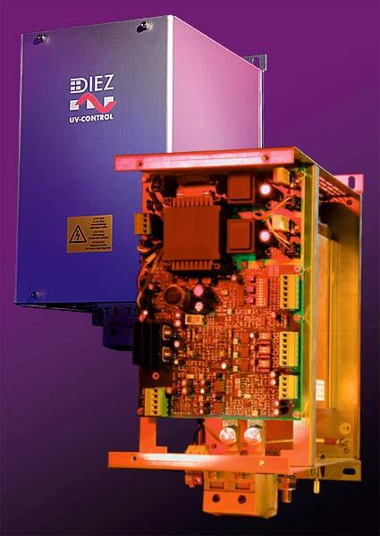
4 4 standard signals via three analogue channels (voltage or current) and be used for process visualization or for feeding to a higher-priority process control system. 5 Design The power section consists of two anti-parallel connected thyristors, the heat sink and the control electronics. In order to measure and record the consumer voltage and the consumer current, a voltage transformer and a current transformer (included in the scope of supply) must be connected externally. This circuit topology is necessary because, for the operation of a gas discharge reflector lamp, non-linear inductivities have to be connected between the thyristor power controller and the gas discharge reflector lamp. 6 Regulations for CE conformity The following standards and regulations form the basis and are observed to the extent that they are applicable: Emitted interference Basic specification DIN EN Radio interference voltage at the power supply terminals EN Class A Interference field strength EN Class A Noise immunity Basic specification DIN EN
5 5 Discharge of static electricity EN KV CD, 8 KV AD High-frequency electromagnetic fields EN MHz, 10 V/m 80 % AM, KHz Fast transients EN KV, 5/50 ns, 5KHz alternating current mains input Surge voltages/surge currents EN /50 (8/20) Tr/Th in µs 4 KV unsym. / 2 KV sym Conducted high frequency EN MHz, 10 V, 80 % AM, I KHz Voltage dips EN % reduction, 10 ms 60 % reduction, 100 ms Voltage interruptions EN % reduction, 5000 ms Electrical safety Electronic equipment for use in power installations EN Protection from electric shock EN Accessories If the thyristor power controller is not used for operation on a gas discharge reflector lamp, as an accessory a fast semi-conductor fuse can be used. The fuse can be used with an appropriate holder on a standard rail or screwed
6 6 onto the built-on plate. The arrangement of the fuse outside of the thyristor power controller facilitates fuse replacement in the event of a fault. For operation of the thyristor power controller on a gas discharge reflector lamp the semi-conductor fuse is not necessary if inductors and transformers from Diez are used as the ballast. These are rated in the technical calculation in such a way that a maximum current rise upon consumer short-circuit is not exceeded. For easy visualization of the electrical variables on the consumer load, the software package DIMO is available. With Dimo the voltage, current and active power at the consumer load can be observed, and represented as a y-t diagram and saved. The saved curves can be measured with the cursor. Dimo is not necessary for the commissioning of the thyristor power controller, it is used merely for easy process visualization. 8 Important installation notes Safety notes For the choice of the lead and cable material, for installation and for electrical connection of the thyristor power controller, the regulations of VDE 0100 "Provisions concerning the construction of electric power installations with rated voltages below AC 1000 volts" or the respective national regulations are to be observed. The electrical connection must be carried out only by specialist personnel. If during work live parts can be touched, the device must be disconnected from the mains at all terminals. Earthing The earthing is to be effected in accordance with the regulations of the responsible utility company.
7 7 Interference suppression The electromagnetic compatibility is in compliance with the standards and regulations listed. Wiring Load and control lines are to be installed separately. For the protection of the lines appropriate fuses are to be provided. Compare the data stated on the rating plate (voltage and current) with the equipment data. Set encoding switch for analogue inputs and analogue outputs. Connect the power supply for the control electronics in accordance with the terminal connection diagram to terminals "L1" and "L2". The electronic switch (2 anti-parallel connected thyristors) is between the connections "U1" and "U2" The power supply for the control electronics and the load voltage must have the same phase angle (synchronization) Closing sequence The power supply for the power and control circuits must be switched on at the same time. The power supply for the control circuit (L1, L2) may only be switched on earlier if the pulse release input has not yet been set and running up of the controllers without consumer load is prevented. That is particularly important during operation of transformer load and with resistive loads with a large hotcold resistive ratio.
8 8 In general the pulse release should only be set when all power supplies have been switched on. That permits safe control over the point in time at which the electric power starts on the consumer load. Filtering and interference suppression To avoid radio interference as naturally arises during generalized phase operation, electrical operating equipment and units have to have radio interference suppression. The control electronics of the thyristor power controller are in compliance with the EMC requirements. Sub-assemblies for generalized phase operation, however, do not in themselves serve any application purpose. They are only a functional unit of an overall plant. Therefore the constructor of a unit must suppress any interference in this unit with the help of suitable filters. Interference suppressor filters are offered as sub-assemblies ready for connection by companies specializing in this field. Place of installation and climatic conditions As far as possible the place of installation should be free of vibrations and closeness to strong electromagnetic fields should be avoided if at all possible. The ambient temperature at the place of use must be 0 45 degrees Centigrade at a relative humidity of < 75 %. As a matter of principle the thyristor power controller is intended for use in dry rooms. The preferred fitting direction is vertical because of the better convection. Care must be taken to ensure adequate ventilation of the switch cabinets. The thyristor power controller is not suitable for use in explosion-hazard areas. The place of installation must be free of aggressive media.


9 9 9 Designation of the control terminals internal X101 X5 monitoring Temperature- 1 monitoring internal X105 X107 internal X108 internal internal X106 internal X109 internal X201 X2 analogue in 6 GND 5 Imax 4 GND 3 Pmax 2 GND 1 Preq. X10 analogue out 6 GND 5 Current 4 GND 3 Voltage 2 GND 1 Power X3 ref/run/stop 10 volts ref. 1 GND 2 Pulse relaese 3 GND 4 24 volts ref 5 X4 C/V transformers 4 b 3 a 2 l 1 k

10 10 10 Encoding switch and potentiometer 1 Imax A Pot Imax 2 Imax B 3 Imax C 4 Pmax A Pot Pmax 5 Pmax B 6 Pmax C 7 Psoll A 8 Psoll B Pot Preq 9 Psoll C 10 Actual value monitoring ON/OFF 1 Iout A 2 Iout B Iout life zero ON/OFF 1 Uout A 2 Uout B Uout life zero ON/OFF 1 Pout A 2 Pout B Pout life zero ON/OFF
11 11 Encoding switch for analogue inputs Table for Imax encoding switch Imax A Imax B Imax C Function volts volts ma Specification via pot on the printed circuit board Table for Pmax encoding switch Pmax A Pmax B Pmax C Function volts volts ma Specification via pot on the printed circuit board Table for Preq encoding switch Imax A Imax B Imax C Function volts volts ma Specification via pot on the printed circuit board Actual value monitoring encoding switch ON : OFF: special mode of operation for inductor parallel operation ( transition inductor) Normal setting for all usual applications
12 12 Encoding switch for analogue outputs Table for Iout encoding switch life zero OFF life zero ON IoutA Iout B Function Function ma 4-20 ma volts 2-10 volts volts 2-10 volts volts 1-5 volts Table for Uout encoding switch life zero OFF life zero ON UoutA Uout B Function Function ma 4-20 ma volts 2-10 volts volts 2-10 volts volts 1-5 volts Table for Pout encoding switch life zero OFF life zero ON PoutA Pout B Function Function ma 4-20 ma volts 2-10 volts volts 2-10 volts volts 1-5 volts
Power supply CP-E 24/20.0
 2CDC 271 027 F0008 a OUTPUT L+, L+, L, L-: terminals output b INPUT L, N, PE: terminals input c 13-14: terminals - signalling contact d OUTPUT OK: green LED output voltage OK e OUTPUT LOW: red LED output
Power supply CP-D 24/1.3
 2CDC 271 027 F0t07 a OUTPUT ++/ : terminals output Features Rated output voltage 24 V DC Output voltage adjustable via front face potentiometer OUTPUT Adjust Rated output current 1.3 A Rated output power
Power supply CP-E 24/2.5
 2CDC 271 015 F0t06 a OUTPUT L+, L : terminals output b DC OK: terminal signalling output c INPUT L, N, PE: terminals input d OUTPUT OK: green LED output voltage OK e OUTPUT Adjust: potentiometer adjustment
Power supply CP-E 24/2.5
 2CDC 271 015 F0t06 a OUTPUT L+, L : terminals output b DC OK: terminal signalling output c INPUT L, N, PE: terminals input d OUTPUT OK: green LED output voltage OK e OUTPUT Adjust: potentiometer adjustment
Power supply CP-E 12/10.0 Primary switch mode power supply Data sheet
 2CDC 271 024 F0008 OUTPUT L+, L+, L-, L-: terminals - output INPUT L, N, PE: terminals - input OUTPUT OK: green LED - output voltage OK OUTPUT LOW: red LED - output voltage too low OUTPUT Adjust: potentiometer
Power supply CP-E 48/5.0 Primary switch mode power supply Data sheet
 2CDC 271 028 F0008 OUTPUT L+, L+, L-, L-: terminals - output Features Rated output voltage 48 V DC Output voltage adjustable via front-face rotary potentiometer OUTPUT Adjust Rated output current 5 A Rated
QUINT-PS/ 3AC/24DC/10
 Primary-switched power supply with SFB technology, 3 AC, output current 10 A INTERFACE Data sheet 103131_en_01 1 Description PHOENIX CONTACT - 09/2009 Features QUINT POWER power supply units Maximum system
Power supply CP-D 12/2.1
 2CDC 271 025 F0t07 a OUTPUT ++/ : terminals output Features Rated output voltage 12 V DC Output voltage adjustable via front face potentiometer OUTPUT Adjust Rated output current 2.1 A Rated output power
IF30. User's manual. Description. Table of contents IF30
 User's manual IF30 Description IF30 is an encoder interface unit designed to convert the output signals delivered by so-called sine-cosine-encoders and similar measuring systems (devices which deliver
QUINT-PS/ 3AC/24DC/40
 Primary-switched power supply unit with SFB technology, 3 AC, output current 40 A INTERFACE Data sheet 103133_en_00 1 Description PHOENIX CONTACT - 07/2009 Features QUINT POWER power supply units Maximum
Power supply CP-E 24/0.75
 2CDC 271 016 F0t06 a OUTPUT L+, L : terminals output b INPUT L, N, PE: terminals input c LOW: red LED output voltage too low d OK: green LED output voltage OK e OUTPUT Adjust: rotary potentiometer output
MINI MCR-SL-UI-f(-SP)
") Configurable Analog Frequency Transducer INTERFACE Data Sheet PHOENIX CONTACT - 02/2006 Description The configurable analog frequency transducer MINI MCR-SL-UI-f(-SP) is used to convert analog standard
Configurable Analog Frequency Transducer INTERFACE Data Sheet PHOENIX CONTACT - 02/2006 Description The configurable analog frequency transducer MINI MCR-SL-UI-f(-SP) is used to convert analog standard
QUINT-PS/ 1AC/24DC/20
 Primary-switched power supply with SFB technology, 1 AC, output current 20 A INTERFACE Data sheet 103129_en_04 1 Description PHOENIX CONTACT - 02/2010 Features QUINT POWER power supply units Maximum system
MINI-PS AC/24DC/1.3
 Power supply unit INTERFACE Data sheet 102894_en_03 1 Description PHOENIX CONTACT 2015-11-17 Features MINI POWER power supplies for MCR technology In measurement and control technology (MCR), modular electronics
XR1 Rotor Earth Fault Relay. (May 2007) Manual XR1 (Revision New)
 Manual XR1 (Revision New)") XR1 Rotor Earth Fault Relay (May 2007) Manual XR1 (Revision New) Woodward Manual XR1 GB Woodward Governor Company reserves the right to update any portion of this publication at any time. Information provided
XR1 Rotor Earth Fault Relay (May 2007) Manual XR1 (Revision New) Woodward Manual XR1 GB Woodward Governor Company reserves the right to update any portion of this publication at any time. Information provided
SIMEAS-T. Operating Instructions Transducer without auxiliary power. 7KG6111 and 7KG6101. Operating Instructions
 Operating Instructions SIMEAS-T s Operating Instructions Transducer without auxiliary power for alternating current for alternating voltage for alternating voltage with expanded end range 7KG6111 and 7KG6101
Power supply CP-D 24/4.2 Primary switch mode power supply
 Data sheet Power supply CP-D 24/4.2 Primary switch mode power supply The CP-D range of modular power supply units in MDRC design (modular DIN rail components) is ideally suited for installation in distribution
Electronic timer CT-TGD.22
 2CDC 251 097 F0t06 a Rotary switch for the preselection of the time range of the ON time b Potentiometer with direct reading scale for the fine adjustment of the ON time c Rotary switch for the preselection
XR1 Rotor Earth Fault Relay. Manual XR1 (Revision C)
") XR1 Rotor Earth Fault Relay Manual XR1 (Revision C) Woodward Manual XR1 (EN) Woodward Governor Company reserves the right to update any portion of this publication at any time. Information provided by
XR1 Rotor Earth Fault Relay Manual XR1 (Revision C) Woodward Manual XR1 (EN) Woodward Governor Company reserves the right to update any portion of this publication at any time. Information provided by
DSA150 Series. xxx Series. 150 Watts. AC-DC Power Supplies. Models & Ratings. Mechanical Details 3.92 (99.8) 2.18 (55.5) 4.92 (125.
 2.18 (55.5) 4.92 (125.") 15 Watts xxx Series Ultra Slim Design 15% Peak Load for 3 seconds Ambient Operation from -1 C to +7 C High Efficiency Selectable Overload Characteristic Selectable Remote Inhibit or Enable 3 Year Warranty
15 Watts xxx Series Ultra Slim Design 15% Peak Load for 3 seconds Ambient Operation from -1 C to +7 C High Efficiency Selectable Overload Characteristic Selectable Remote Inhibit or Enable 3 Year Warranty
UNO-PS/1AC/24DC/150W. Primary-switched power supply unit. Data sheet. 1 Description
 Primary-switched power supply unit Data sheet 106261_en_02 PHOEIX COTACT 2015-05-13 1 Description The power supply makes a worldwide impression thanks to maximum energy efficiency. ow idling losses (o
PHOENIX CONTACT - 06/2008. Features. DANGER OF EXPLOSION! Only remove equipment when it is disconnected and not in the potentially explosive area.
 Primary-switched power supply with SFB technology, 1 AC, output current 20 A INTERFACE Data Sheet 103383_en_00 1 Description PHOENIX CONTACT - 06/2008 Features QUINT POWER power supply units highest system
Type CP-S, CP-C & CP-A Switch mode
 Switch mode power CP-S, CP-C & CP-A Switch mode Characteristics CP-S and CP-C range Output current 5 A, 10 A and 20 A Integrated power reserve of up to 50 % 5 A and 10 A devices with pluggable connecting
QUINT-PS-24DC/24DC/10
 QUINT-PS-24/24/10 QUINT - converter, primary switched mode, input: 24 V, output: 24 V /10 A INTERFACE Data Sheet PHOENIX CONTACT - 02/2006 Description The QUINT - converter 24 V/10 A converts the voltage
MINI-PS AC/2X15DC/1
 MII-PS-100-240AC/2X15DC/1 Power supply unit ITERFACE Data sheet 100299_en_04 1 Description PHOEIX COTACT - 2010-10-20 Features MII POWER is the extremely slim power supply unit with constructional widths
Multi-function (MI, ME, M2, M1) 2 NO (2 SPST-NO) 12 / / 400 3,000 1, / 0.3 / (5 / 5) AgNi
 2 NO (2 SPST-NO) 12 / / 400 3,000 1, / 0.3 / (5 / 5) AgNi") Features Special relay for alternating loads, for applications with pumps, compressors, air conditioning or refrigeration units 2 independent NO output, 12 A 4 functions 2 independent control signals,
Features Special relay for alternating loads, for applications with pumps, compressors, air conditioning or refrigeration units 2 independent NO output, 12 A 4 functions 2 independent control signals,
PHOENIX CONTACT - 05/2008. DANGER OF EXPLOSION! Remove an item only when it is not connected to power or if it is located in the non-explosive area.
 Primary-switched power supply with SFB technology, 1 AC, output current 20 A INTERFACE Data Sheet 103129_en_01 PHOENIX CONTACT - 05/2008 1 Description QUINT POWER power supply units highest system availability
XUA1 AC Voltage and phase balance relay. (August 1996) Manual XUA1 (Revision New)
 Manual XUA1 (Revision New)") XUA1 AC Voltage and phase balance relay (August 1996) Manual XUA1 (Revision New) Woodward Manual XUA1 GB Woodward Governor Company reserves the right to update any portion of this publication at any time.
XUA1 AC Voltage and phase balance relay (August 1996) Manual XUA1 (Revision New) Woodward Manual XUA1 GB Woodward Governor Company reserves the right to update any portion of this publication at any time.
Output Voltage* (nom.)(adjustable)
(adjustable)") Industrial Power Supplies TIB Series, 80 480 W Slim profile, reduced module width High Power Factor up to 99% High efficiency up to 94% True back power immunity Low heat dissipation 150% peak current Automatic
Industrial Power Supplies TIB Series, 80 480 W Slim profile, reduced module width High Power Factor up to 99% High efficiency up to 94% True back power immunity Low heat dissipation 150% peak current Automatic
XF2 Frequency Relay. Manual XF2 (Revision A)
") XF2 Frequency Relay Manual XF2 (Revision A) Woodward Manual XF2 GB Woodward Governor Company reserves the right to update any portion of this publication at any time. Information provided by Woodward Governor
XF2 Frequency Relay Manual XF2 (Revision A) Woodward Manual XF2 GB Woodward Governor Company reserves the right to update any portion of this publication at any time. Information provided by Woodward Governor
Installation and Operational Instructions for ROBA -switch Type 017._00.2
 Manufacturer s Declaration This product is intended for installation in a machine or system, based on the machine directive 2006/42/EC. It is forbidden to start use of the product until the machine or
Electronic timer CT-SDD.22
 CDC 099 F0t0 a Rotary switch for the preselection of the time range b Potentiometer with direct reading scale for the fine adjustment of the time delay c U: green LED V control supply voltage applied W
QUINT-PS AC/24DC/40
 Power supply unit INTERFACE Data sheet 102315_en_02 1 Description PHOENIX CONTACT 2010-04-23 Features QUINT POWER power supply units for plant and special engineering reliably start heavy loads with high
Immunity Testing for the CE Mark
 Immunity Testing for the CE Mark Summary The European Union (EU) currently has 25 member countries with 2 additional countries to be added in 2007. The total population at that time will be nearly a half
CM-MPS.11, CM-MPS-21, CM-MPS.31 and CM-MPS.41 Data sheet. UL 508, CAN/CSA C22.2 No.14 GL GOST CB scheme CCC
 2CDC 251 048 F0t08 CM-MPS.11 2CDC 251 049 F0t08 CM-MPS.21 Features Monitoring of three-phase mains for phase sequence (can be switched off), phase failure, over- and undervoltage as well as phase unbalance
Overcurrent Protection / 7SJ45
 Overcurrent Protection / SJ SIPROTEC easy SJ numerical overcurrent protection relay powered by CTs Fig. / Description SIPROTEC easy SJ numerical overcurrent protection relay powered by current transformers
VIM Series. 90 & 60 W, Efficient, CV Class 2 LED Drivers ORDERING INFORMATION
 060W-12 100W-24 Nominal Input Voltage 90 &, Efficient, CV Class 2 Max. Output Power Nominal Output Voltage Max. Output Current 120 & 277 Vac 12, 24 Vdc 5, 3.75 A Efficiency up to 90% typical Max. Case
SIPROTEC easy 7SJ46 Numerical Overcurrent Protection Relay
 Overcurrent Protection / 7SJ46 SIPROTEC easy 7SJ46 Numerical Overcurrent Protection Relay Function overview Fig. /11 Description The SIPROTEC easy 7SJ46 is a numerical overcurrent protection relay which
Introduction EMC. Filter parameters. Definition of EMC / EMI. X-Capacitor. Sources of EMI. Coupling mechanism. Y-Capacitor.
 Introduction to EMC Schurter has over 75 years experience in the electronics and electrical industries, developing and manufacturing components that ensure a clean and safe supply of power. Schurter provides
Power supply CP-T 48/20.0 Primary switch mode power supply
 Data sheet Power supply CP-T 48/20.0 Primary switch mode power supply The CP-T range of three-phase power supply units is the youngest member of ABB s power supply family. In terms of design and functionality,
Proportional amplifier type EV22K5
 Proportional amplifier type EV22K5 Assembly instructions Card design Supply voltage UB: Output current QA max: 9...32 V DC 1.8 A by HAWE Hydraulik SE. The forwarding and reproduction of this document,
High precision measurement system for current and voltage IHC-A/B-RM01/03
 Measurement Offset-free and low-noise 16 bit data acquisition system ISA-ASIC Internal sample rate 3,500 Hz Communication Standard RS232- or RS485 interface Advantages Direct measurement on the bus bar
ABB NEW. Multifunctional three-phase monitoring relays. CM-MPS.23 and CM-MPS.43 Data sheet. Features J. Approvals. Marks.
 2CDC 251 052 F0t08 CM-MPS.23 2CDC 251 053 F0t08 CM-MPS.43 - relay status, timing - fault message - fault message Adjustment of the tripping delay t V Adjustment of the threshold value for overvoltage 6
Product Specification sheet
 INPUT MINIMUM RATED MAXIMUM Input Voltage 90V AC 100 240V AC 264V AC Input Frequency 47 Hz 50 / 60 Hz 63 Hz Input Current * 350mA Inrush Current **
Electronic timer CT-WBS.22 Impulse generating and flashing with 2 c/o (SPDT) contacts
 contacts") Data sheet Electronic timer CT-WBS.22 Impulse generating and flashing with 2 c/o (SPDT) contacts The CT-WBS.22 is a multifunctional electronic timer from the CT-S range. It provides 10 timing functions
Data sheet Electronic timer CT-WBS.22 Impulse generating and flashing with 2 c/o (SPDT) contacts The CT-WBS.22 is a multifunctional electronic timer from the CT-S range. It provides 10 timing functions
XUA1 - AC Voltage and phase balance relay
 XUA1 - AC Voltage and phase balance relay Contents 1. Applications and features 2. Design 3. Function 3.1 Voltage supervision 3.2 Unbalanced voltage supervision 4. Operation and settings 4.1 Setting of
Power supply CP-T 24/40.0 Primary switch mode power supply
 Data sheet Power supply CP-T 24/40.0 Primary switch mode power supply The CP-T range of three-phase power supply units is the youngest member of ABB s power supply family. In terms of design and functionality,
DSR120 Series. xxx Series. 120 Watts. AC-DC Power Supplies. Models & Ratings. Mechanical Details
 120 Watts xxx Series Ultra Slim Design - 32 mm 150% Peak Load for 3 seconds Ambient Operation from -25 C to +70 C Full Load at 60 C (24V/48V) High Efficiency - Up to 92% Volt-Free Contact for OK Selectable
Power supply CP-T 24/20.0 Primary switch mode power supply
 Data sheet Power supply CP-T 24/20.0 Primary switch mode power supply The CP-T range of three-phase power supply units is the youngest member of ABB s power supply family. In terms of design and functionality,
Electronic timer CT-SDS.22 Star-delta change-over with 2 n/o contacts Data sheet
 CDC 0 F0t07 Features Rated control supply voltage -8 V DC, -0 V AC Single-function timer with star-delta change-over One device includes 7 time ranges (0.0 s - 0 min) n/o contacts LEDs for status indication
Output Voltage nom. (adjustable)
") Industrial Power Supplies TIB Series, 80 480 W Slim profile, for DI-rail mounting Alternative side-mounting for flat panels High power factor by active power correction Very high efficiency up to 94.5%
Industrial Power Supplies TIB Series, 80 480 W Slim profile, for DI-rail mounting Alternative side-mounting for flat panels High power factor by active power correction Very high efficiency up to 94.5%
Installation and Operational Instructions for ROBA -multiswitch Type 019._00.2
 Guidelines on the Declaration of Conformity A conformity evaluation has been carried out for the product in terms of the EU Low Voltage Directive 2014/35/ EU and the Electromagnetic Compatibility (EMC)
Electronic timer CT-AHS.22 OFF-delayed with 2 c/o (SPDT) contacts
 contacts") Data sheet Electronic timer CT-AHS.22 OFF-delayed with 2 c/o (SPDT) contacts The CT-AHS.22 is an electronic timer from the CT-S range with OFF-delay and 10 time ranges. All electronic timers from the CT-S
Data sheet Electronic timer CT-AHS.22 OFF-delayed with 2 c/o (SPDT) contacts The CT-AHS.22 is an electronic timer from the CT-S range with OFF-delay and 10 time ranges. All electronic timers from the CT-S
08/07/2015
 17.5 mm - 1 Solid State Relay 0.7A MUS2 Part number 88827004 Multi-function or mono-function Multi-range Multi-voltage Screw or spring terminals LED status indicator (relay version) Possibility of external
Output Voltage nom. (adjustable)
") Industrial Power Supplies TIB Series, 80 480 W Slim profile, reduced module width Alternative side-mounting for flat panels Active Power Factor High efficiency up to 94% Back power immunity 150% peak current
Industrial Power Supplies TIB Series, 80 480 W Slim profile, reduced module width Alternative side-mounting for flat panels Active Power Factor High efficiency up to 94% Back power immunity 150% peak current
BIODEX MULTI- JOINT SYSTEM
 BIODEX MULTI- JOINT SYSTEM CONFORMANCE TO STANDARDS 850-000, 840-000, 852-000 FN: 18-139 5/18 Contact information Manufactured by: Biodex Medical Systems, Inc. 20 Ramsey Road, Shirley, New York, 11967-4704
Type 3RW RW40 7. Control electronics Rated values. Terminal. external DC supply (to DIN 19240) through terminals and IN Relay outputs
 through terminals and IN Relay outputs") Function have all the same advantages as the 3RW30/31 soft starters. At the same they come with additional functions and a two-phase control method (Polarity Balancing) that is unique in the rating range
Function have all the same advantages as the 3RW30/31 soft starters. At the same they come with additional functions and a two-phase control method (Polarity Balancing) that is unique in the rating range
Electronic timer CT-TGD.12 Pulse generator with 1 c/o (SPDT) contact
 contact") Data sheet Electronic timer CT-TGD.12 Pulse generator with 1 c/o (SPDT) contact The CT-TGD.12 is an electronic time relay with the function pulse generator. It is from the CT-D range. With their MDRC profile
Data sheet Electronic timer CT-TGD.12 Pulse generator with 1 c/o (SPDT) contact The CT-TGD.12 is an electronic time relay with the function pulse generator. It is from the CT-D range. With their MDRC profile
ABB 1. Multifunctional three-phase monitoring relays. CM-MPS.11, CM-MPS-21, CM-MPS.31 and CM-MPS.41 Data sheet. Features. Approvals. Marks.
 2CDC 251 048 F0t08 CM-MPS.11 2CDC 251 049 F0t08 CM-MPS.21 2CDC 251 050 F0t08 CM-MPS.31 2CDC 251 051 F0t08 CM-MPS.41 R/T: yellow LED - relay status, timing F1: red LED - fault message F2: red LED - fault
CP-T range Product group picture
 Product group picture /1 ABB Catalog Electronic Products and Relays 1/1 2CDC 110 00 C09 Table of contents CP-T range Product group picture /1 Table of contents /2 Benefits and advantages / Ordering details
MID energy meter B21 Single-phase energy meter, 65 A
 MID energy meter B2 Single-phase energy meter, 5 Single-phase energy meter ( + ) Direct connection up to 5 Width, 2 DI modules Tested and approved per MID * and IEC * Regional different requirements apply
Installation and Operational Instructions for ROBA -switch Type 017._00.2
 OBA -switch Type 017._00.2 Guidelines on the Declaration of Conformity A conformity evaluation has been carried out for the product in terms of the EC Low Voltage Directive 2014/35/ EC and the EMC Directive
Passive Current Transducers for Sinusoidal Alternate Currents From A/0...5 A MCR-SLP-1/5-UI-0(-SW)
") Passive Current Transducers for Sinusoidal Alternate Currents From 0... A/0...5 A (-SW) Passive current transducer without power supply Measuring range A and 5 A AC, reconnectable Available with threshold
Passive Current Transducers for Sinusoidal Alternate Currents From 0... A/0...5 A (-SW) Passive current transducer without power supply Measuring range A and 5 A AC, reconnectable Available with threshold
STEP-UPS/24DC/24DC/3. Uninterruptible power supply. Data sheet. 1 Description. Features
 Uninterruptible power supply Data sheet 105623_en_00 PHOENIX CTACT 2013-06-07 1 Description Uninterruptible power supply units continue to deliver power even in the event of mains breakdowns or failures.
One-day Conference 18 March Power Supply, EMC and Signalling, in Railway Systems
 One-day Conference 18 March 2017 Power Supply, EMC and Signalling, in Railway Systems EMC Management and Related Technical Aspects in Railway Systems By Dr Peter S W LEUNG http://www.ee.cityu.edu.hk/~pswleung/
XU2-AC AC voltage relay. (Februar 1997) Manual XU2-AC (Revision New)
 Manual XU2-AC (Revision New)") XU2-AC AC voltage relay (Februar 1997) Manual XU2-AC (Revision New) Woodward Manual XU2-AC GB Woodward Governor Company reserves the right to update any portion of this publication at any time. Information
XU2-AC AC voltage relay (Februar 1997) Manual XU2-AC (Revision New) Woodward Manual XU2-AC GB Woodward Governor Company reserves the right to update any portion of this publication at any time. Information
Power supply CP-T 48/5.0 Primary switch mode power supply
 Data sheet Power supply CP-T 48/5.0 Primary switch mode power supply The CP-T range of three-phase power supply units is the youngest member of ABB s power supply family. In terms of design and functionality,
Power supply CP-T 24/10.0 Primary switch mode power supply
 Data sheet Power supply CP-T 24/10.0 Primary switch mode power supply The CP-T range of three-phase power supply units is the youngest member of ABB s power supply family. In terms of design and functionality,
Controls Solid-State Switching Devices
 Controls Solid-State Switching Devices /2 Introduction Solid-State Switching Devices /3 General data Solid-State Relays /5 General data /6 3RF21 solid-state relays, 22.5 mm /12 3RF20 solid-state relays,
Electronic timer CT-AHS.22 OFF-delayed with 2 c/o (SPDT) contacts
 contacts") Data sheet Electronic timer CT-AHS.22 OFF-delayed with 2 c/o (SPDT) contacts The CT-AHS.22 is an electronic timer from the CT-S range with true OFF-delay and 10 time ranges. All electronic timers from
Data sheet Electronic timer CT-AHS.22 OFF-delayed with 2 c/o (SPDT) contacts The CT-AHS.22 is an electronic timer from the CT-S range with true OFF-delay and 10 time ranges. All electronic timers from
Subject to changes 11/2003 Page 1/7
 Main Characteristics: Zero switching. LED display. Various connection systems. Plug-in control terminal. Degree of protection IP 2. Double-insulated design. General Data: Standards / Approvals DIN EN 697--3
XP2-R Power and Reverse Power Relay
 XP2-R Power and Reverse Power Relay Manual XP2-R (Revision C) Woodward Manual XP2-RE Woodward reserves the right to update any portion of this publication at any time. Information provided by Woodward
Electronic timer CT-MVS.23 Multifunctional with 2 c/o (SPDT) contacts
 contacts") Data sheet Electronic timer CT-MVS.23 Multifunctional with 2 c/o (SPDT) contacts The CT-MVS.23 is a multifunctional electronic timer from the CT-S range. It provides 11 timing functions and 10 time ranges.
Data sheet Electronic timer CT-MVS.23 Multifunctional with 2 c/o (SPDT) contacts The CT-MVS.23 is a multifunctional electronic timer from the CT-S range. It provides 11 timing functions and 10 time ranges.
Scale Manufacturers Association (SMA) Recommendation on. Electrical Disturbance
 Recommendation on. Electrical Disturbance") Scale Manufacturers Association (SMA) Recommendation on Electrical Disturbance (SMA RED-0499) Provisional First Edition Approved by SMA Pending Final Comment April 24, 1999 Copyright: SMA, April, 1999
Scale Manufacturers Association (SMA) Recommendation on Electrical Disturbance (SMA RED-0499) Provisional First Edition Approved by SMA Pending Final Comment April 24, 1999 Copyright: SMA, April, 1999
CP-T range Benefits and advantages
 Benefits and advantages Characteristics Rated output voltages V, V DC Output voltage adjustable via front-face rotary potentiometer OUTPUT Adjust Rated output currents 5 A, 10 A, A, A Rated output powers
Temperature monitoring relays CM-TCS Monitoring relays for monitoring temperatures with a PT100 sensor (2- or 3-wire connection)
") Data sheet Temperature monitoring relays CM-TCS Monitoring relays for monitoring temperatures with a PT100 sensor (2- or 3-wire connection) The temperature monitoring relays CM-TCS monitor overtemperature,
Data sheet Temperature monitoring relays CM-TCS Monitoring relays for monitoring temperatures with a PT100 sensor (2- or 3-wire connection) The temperature monitoring relays CM-TCS monitor overtemperature,
CB Scheme UL508 UL ATEX II3G
 Industrial Power Supplies UL Hazloc Class I, division 2 approval and ATEX certification SEMI F47 compliant for voltage sag immunity Rugged metal case with optional side-mounting Very high efficiency up
XN2 - Mains decoupling relay. Manual XN2 (Revision C)
") XN2 - Mains decoupling relay Manual XN2 (Revision C) Woodward Manual XN2 GB Woodward Governor Company reserves the right to update any portion of this publication at any time. Information provided by Woodward
XN2 - Mains decoupling relay Manual XN2 (Revision C) Woodward Manual XN2 GB Woodward Governor Company reserves the right to update any portion of this publication at any time. Information provided by Woodward
XP2-R Power and reverse power relay. (January 2006) Manual XP2-R (Revision New)
 Manual XP2-R (Revision New)") XP2-R Power and reverse power relay (January 2006) Manual XP2-R (Revision New) Woodward Manual XP2-R GB Woodward Governor Company reserves the right to update any portion of this publication at any time.
XP2-R Power and reverse power relay (January 2006) Manual XP2-R (Revision New) Woodward Manual XP2-R GB Woodward Governor Company reserves the right to update any portion of this publication at any time.
Three-phase monitoring relays
 2CDC 251 046 F0t08 Features Monitoring of three-phase mains for phase sequence, phase failure, phase unbalance Threshold value for phase unbalance adjustable as absolute value Tripping delay can be adjusted
LZS-A500-3 POWER SUPPLY Installation, Operation, and Maintenance Manual. IM-LZSA500-3 January 2008 Revision H
 LZS-A500-3 POWER SUPPLY Installation, Operation, and Maintenance Manual IM-LZSA500-3 January 2008 Revision H Table of Contents LZS-A500-3 Power Supply 1) Safety and Recommended Practices 2 1.1 General
RS Pro ENGLISH. Datasheet
 Datasheet Article No: 136-5385 Digital AC Ammeter, 48x96, 1Phase, 1 or 5 Amps AC, Supply 40-300V ac/dc 136-5387 Digital AC Ammeter, 96x96, 1Phase, 1 or 5 Amps AC, Supply 40-300V ac/dc 136-5388 Digital
Measuring and monitoring relays CM-SRS.1 Current monitoring relays, single-phase AC/DC
 2CDC 251 244 F0t05 Characteristics Monitoring of DC and AC currents: RMS measuring principle One device includes 3 measuring ranges Over- or undercurrent monitoring configurable Hysteresis adjustable from
Industrial motor controller for brushed DC motors 12 VDC
 Industrial motor controller for brushed DC motors 12 VDC Design for output currents up to 5 A Control with the following functions: - reversal of direction of rotation - rotational speed control (external)
ABB NEW. Three-phase monitoring relays. CM-PVS.31 and CM-PVS.41 Data sheet. Features J. Approvals. Marks. Order data. Order data - Accessories
 2CDC 251 042 F0t08 CM-PVS.31 Features Monitoring of three-phase mains for phase sequence (can be switched off), phase failure, over- and undervoltage Threshold values for over- and undervoltage are adjustable
ABB 1. Multifunctional three-phase monitoring relays. CM-MPN.52, CM-MPN.62 and CM-MPN.72 Data sheet. Features. Approvals. Marks.
 2CDC 251 054 F0t08 CM-MPN.52 2CDC 251 055 F0t08 CM-MPN.62 2CDC 251 056 F0t08 CM-MPN.72 Features Monitoring of three-phase mains for phase sequence (can be switched off), phase failure, over- and undervoltage
MCR-VAC-UI-0-DC. Voltage transducer for AC voltages. INTERFACE Data sheet _en_02. 1 Description
 Voltage transducer for AC voltages TERFACE Data sheet 006_en_0 PHOENIX CONTACT 00-0- Description The MCR voltage transducer measures AC voltages in several signal ranges from 0... ±4 V AC to 0... ±30 V
Liquid level monitoring relay CM-ENS.2x
 Data sheet Liquid level monitoring relay CM-ENS.2x The CM-ENS.2x is served to regulate and control liquid levels and ratios of mixtures of conductive fluids. It can be used for overflow protection, dry
Guidance and Declaration - Electromagnetic Compatibility (EMC) for the Delfi PTS ii Portable Tourniquet System
 for the Delfi PTS ii Portable Tourniquet System") Guidance and Declaration - Electromagnetic Compatibility (EMC) for the Delfi TS ii ortable Tourniquet System Guidance and manufacturer s declaration electromagnetic emissions The TS ii ortable Tourniquet
Guidance and Declaration - Electromagnetic Compatibility (EMC) for the Delfi TS ii ortable Tourniquet System Guidance and manufacturer s declaration electromagnetic emissions The TS ii ortable Tourniquet
Operating Manual * * Differential pressure transmitter. Table of Contents. 1 Safety guidelines. 1.1 General Information
 *09005137* BA_EN_DE50 Rev.A 11/12 *09005137* d e v e l o p i n g s o l u t i o n s DE50 Operating Manual Differential pressure transmitter Table of Contents 1 Safety guidelines 2 Application purpose 3
02/11/2015
 35 mm - 1 Relay 8A OUR3 Part number 88867103 Multi-function or mono-function Multi-range Multi-voltage Relay output 1 or 2 : 8 A - 250 V (10 A UL) LED status indicator Option of connecting an external
MDW-45 Converter RS RS-422/485
 www.westermo.com MDW-45 Converter RS-232 - RS-422/485 2 6617-2203 General information Legal information The contents of this document are provided as is. Except as required by applicable law, no warranties
This annex is valid from: to Replaces annex dated: Locations where activities are performed under accreditation
 Annex to declaration accreditation (scope accreditation) Locations where activities are performed under accreditation Location Abbreviation/ location code Head Location Vijzelmolenlaan 5 & 7 3447 GX oerden
VGM Series. 100 & 60 W, Efficient, CV Class 2 LED Drivers for Signage Applications ORDERING INFORMATION
 Nominal Input Voltage Max. Output Power Nominal Output Voltage Max. Output Current 120/277 Vac 12, 24, Vdc 5, 3.92 A Efficiency up to 90% typical Max. Case Temperature 100 C (measured at the hot spot)
USER MANUAL XLB-2500 Short Arc Xenon Lamp Ballast
 USER MANUAL XLB-2500 Short Arc Xenon Lamp Ballast The XLB-2500 Xenon lamp ballast is a very compact power supply designed for OEM applications. The XLB-2500 is ideal for high power applications where economy
02/11/2015
 Modem communication plug and play solutions GSM Part number 88970119 For remote control of your application Automatic notification of alarms via SMS (GSM Modem) / email or on a PC with M3 ALARM software.
02/11/2015
 Modem communication plug and play solutions GSM Part number 88970119 For remote control of your application Automatic notification of alarms via SMS (GSM Modem) / email or on a PC with M3 ALARM software.
PRetrans Table of contents
 HART TRANSPARENT REPEATER PRetrans 5106 Table of contents Warnings 16 Safety instructions 17 EC Declaration of Conformity 19 How to demount SYSTEM 5000 20 Application 21 Technical characteristics 21 Mounting
Appendix A: Specifications
 All specifications apply to the TDS 200-Series Digital Oscilloscopes and a P2100 probe with the Attenuation switch set to 10X unless noted otherwise. To meet specifications, two conditions must first be
Electronic timer CT-MFS.21
 2CDC 251 053 F0t07 a Rotary switch for the preselection of the time range b Potentiometer with direct reading scale for the fine adjustment of the time delay c Rotary switch for the preselection of the