RF Field Strength Analyzer
|
|
|
- Neil Ray
- 5 years ago
- Views:
Transcription

1 99 Washington Street Melrose, MA Phone Toll Free Visit us at RF Field Strength Analyzer USER S MANUAL 1
2 3201N/3290N USER S MANUAL In order to keep the Protek 3201N/3290N RF Field Strength Analyzer continuously updated, information in this manual is subject to change without notice. Please contact us, if you have any question about version upgrade and amendment. 2
3 Safety Term and symbols Danger statements identify condition or practices that could result in injury or loss of life. Caution statements identify conditions or practices that could result in damage or fire.. Ground statements identify conditions or practices that could connect protective conductor. 3
4 3201N/3290N USER S MANUAL Caution for safety Prohibiting to removal the cover Do not remove the instrument cover to access the internal components. Only GS Instruments Service team or technician with knowledge of the instruments condition and dangerous voltages can repair the instrument. Instruments that appear damaged or defective should be made inoperative and secured against unintended operation until they can be repaired by qualified service personnel. Keep the clean on power insert Instrument s power insert should remain dust free. Clean the power insert regularly. Dust could result in damage to this instrument. Continually clean the dust on input terminal of RF frequency counter. Clean the input terminal regularly. Dust could result in damage to the instrument. RF in/output rating Rating of RF input and output connector Maximum DC voltage rating RF input connector (socket): N type female, 50Ohms Maximum RF input power: 5Vrms Caution: Do not use over 5Vrms supplied and/or (-) power could result in damage to this instrument Do not operate this instrument if there is any doubt it is functioning properly: if operating personnel feel the instrument is not operating properly, return this instrument to GS Instrument for service and repair to ensure the safety features are maintained. 4
5 DC Power The operating Personnel must use the DC adaptor supplied, combining this instrument. The other adaptor could result in damage to this instrument and it is the limitation of warranty Exterior DC input connector should be matched with polar. DC connector tip must attach with (+) polar grounding. The operating personnel must use grounded power Restore this instrument Restore this instrument Do not attempt to operate this instrument for long durations and avoid restoring this instrument. *Avoid direct light *Keep away the heating system *Avoid high temperature (Ex. Inside of the car during the summer time) *Keep about from liquids *Avoid high moisture and/or poor ventilation *Keep away dust and/or smoke *Avoid extremely low temperature Keep away from hazard of return strokes 5
6 3201N/3290N USER S MANUAL Protek 3201N/3290N Ni-MH battery is rechargeable. Battery is recharged bases on the battery temperature. Charging is controlled from the power of the battery cell and the temperature of the battery. Ni-MH Rechargeable battery is going to increase temp slowly until the temperature is extremely higher. Battery charging is finished automatically by checking the degree of the temperature (dt/dt). For battery protection, when the power of Battery cell is increased, comparing regular temperature and/or exterior temperature degree of when the temperature increases over 50 degrees, battery charging will be finished automatically. Operating personnel must use Ni-MH Rechargeable Battery and do not operate in an explosive atmosphere. - The battery usage time can change due to the using term, environment and temperature. - When battery consumption is large battery-running time will decrease. Operating personnel should phase in a new battery when battery-running time is less than half (Warrant period is 6 month, after instrument use has begun.) - Operating personnel should not use this instrument and/or keep the battery in place for long periods of time, which could result in discharge of the battery. - To avoid damages to battery, when battery is low, this instrument will turn off automatically. 6
7 Warranty Limited Warranty. GS Instrument product is warranted against defects in material and workmanship for a period of one year from the date of shipment. During the warranty period, GS Instrument Company will, at its option, either repair or replace products that prove to be defective. Below is the limitation of warranty per this manual: Buyer misuse, unauthorized modification or repair of product Operating personnel use this instrument against specification. Defect resulting from improper or inadequate maintenance by buyers. Defect is Caused by the environment such as fire, flood or earthquake. Buyer installs substitute parts or performs any unauthorized circuit and/or consumption good substitution. Buyer operates instrument against the environmental specifications for this instrument. With the exception of the above articles, GS Instruments product is warranted for initial purchaser. If this instrument is resold the end-user, warranty is not transferred. The foregoing warranty shall not apply to defects resulting from outside the environment and/or misuse. 7


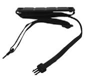
8 Accessories Carrying case AC Adaptor Carrying Strap Coaxial Cable RS-232 Cable Power Cable Ear Phone N-BNC Adaptor Ni-MH(Rechargeable Battery) 6PCS User s Manual /GUI Sofware Guide GUI Software CD Antenna Standard Option 8
9 Table of contents 1. Introduction Overview Features Main features Functions RF Field Strength Analyzer...13 Frequency Counter..13 Specifications Instrument overview Front Panel Rear Panel.20 Side Panel.21 Top Panel Basic operation Before Power On..23 Power On...24 Turn on Power of Instrument...25 Description of operation screen...26 Reception Mode...32 Sweep Mode.33 Set up Span...34 Frequency Input Adjust Screen Level..37 Run - Scanning Marker...39 Power Meter 46 Setting of attenuator.49 LCD Light...50 LCD Contrast.51 Buzzer ON/OFF
10 3201N/3290N USER S MANUAL Save/Load..53 Frequency Counter..57 Power Source...59 Level Unit...60 Reset.. 61 Baud Rate.. 62 Connection for PC 63 Auto Power 64 Offset.. 65 Menu...66 System Description of key operating Run [GHz]. 73 Mode [MHz].. 73 Sweep [khz]. 74 Marker [DEL] 74 No. 1 [Start/Stop]. 75 No. 2 [Span].. 75 No. 3 [Level]. 76 No. 4 [Single] No. 5 [Multi] 77 No. 6 [UNIT] No. 7 [LCD Light]. 78 No. 8 [LCD CONT; LCD Contrast] 78 No. 9 [Attenuator] 79 No. 0 [system].. 79 Shift. 80 Dot [Buzzer].. 80 Menu [Load]. 81 Enter [Save]. 81 Up/Down Keys and Knob Key Test Equipment Depot Washington Street Melrose, MA FAX TestEquipmentDepot.com
11 Introduction 1 Overview The Protek 3201N/3290N is handheld RF Field Strength Analyzer and it is optimized to analyze a signal for the radio frequency equipment that is increased for the use of frequency, gradually high-speeded, and digitalized. The Protek 3201N/3290N has adopted synthesizer method and has a wideband reception range of 100 khz to 2,900 MHz. The characteristic of frequency response of the Protek 3201N/3290N is calculated by memorized calculation data, and so it enables the Protek 3201N/3290N to measure accurate level and make easy analysis for wide range of frequency band. The Protek 3201N/3290N provides various functions and user-friendly interface which makes it easy for the user to check the location of the antenna with simple handling. The Spectrum Analyzer is ideal for user to test, install and maintain Mobile Telecommunications Systems, Cellular and Cordless Phone, CB Paging, Paging Systems, Cable and Satellite TV Systems as well as antenna site measurements and maintenance. The Protek 3201N/3290N supports RS 232C serial communication and has separate GUI software. So, user can control the Protek 3201N/3290N easily after connecting the Protek 3201N/3290N with his personal computer, and can utilize the analyzed data variously after converting or saving numerical value or graph. 11
12 3201N/3290N USER S MANUAL Features 2 Main features 100 khz to 2,900 MHz measurement range(3201n:2,000mhz) Frequency Spectrum Analyzing Function and Frequency Counter Function Measure and demodulates N-FM, W-FM, AM, SSB signals Built-in 2 GHz Frequency Counter Accurate Signal Level Measurement Marker/delta Marker/Squelch Adjustment Function PLL tuning system for precise frequency tuning Built-in Speaker 192 Pixels X 192 Pixels Back Light LCD Menu selection method for Function selection RS-232C Interface User-friendly Icon Display Maintenance of Wireless Telecommunications Equipments General Usage for Installation and Maintenance of telecommunications Equipments Installation and Maintenance of Cable RFID Tag RF Strength Measurement Jammer (for hospital, theater and military) Performance Test Installation and Maintenance of Satellite Antenna Detection of Tapping and Hidden Camera 12
13 Functions 3 RF Field Strength Analyzer Spectrum: Peak Search, Marker to Center, Channel Power Function Internal Attn.: The input range can be extended by internal Max 10 db Attn. function. Sweep Mode: Single Run, Free Run, Squelch Run Selectable Squelch Function: The Squelch Level may be adjusted to any value from the reference level to Full Scale. Copy Function: The Copy Set mode allows the contents of the Channels edit Setup and Data memories to be copied to an external device. Data may also be written into these memories from external device Frequency Counter Frequency range: 35 MHz to 2,900 MHz (3201N:2,000MHz) No. of digits: 7 digits Resolution: 1 khz 13
14 3201N/3290N Frequency Frequency Range Resolution Accuracy W-FM / N-FM / AM / SSB Step Range 100 khz to 2,900 MHz (3201N:2,000MHz) Min khz (Multiple of 6.25kHz) TXO : ± 3 PPM / Display : ± 1.5 PPM Wide FM : Approx. 180 db Narrow FM : Approx db AM/SSB : Approx. 2.4 db NFM/AM/SSB : 1.2MHz WFM : 1MHz(1~20MHz), 20MHz(20~400MM) Span Range Frequency Selection Mode AM, SSB, Narrow FM : 1MHz, 2MHz Wide FM : 1~20MHz (Multiple of 1 MHz) 20~400MHz (Multiple of 20 MHz) Center, Start/ Stop, Span Amplitude Measurement Range Average noise Level -45 dbm to 110 dbm WFM/AM/SSB : -100dBM NFM : -110 dbm Amplitude Units Reference Level Accuracy Reference Level Range Log Scale Internal Attn (Manual/Auto) Internal Attn Accuracy dbm, dbmv, dbuv Typical ±2.0 db (@20~30 /W-FM) Typical ±2.0 db (@25 /N-FM/AM/SSB) 0 ~ -80dBm 0.2 db/div min, in 0.25 db Span (5 Display Division) 10 db (Default, 10dB Auto Atten.) ±1.0 db (@25 ) 14
15 asdf Sweep Speed Trigger Source Trigger Mode Trigger Level Marker Mode Min. 500 msec Narrow FM / Wide FM / AM / SSB Free Run / Single Run / Continuous Wave / Squelch Run TTL Level Maker / Delta Maker Memory Trace & Setup Storage Max 100 Waveforms and 100 States Display Type Display Resolution LCD Light Mono STN LCD 192 Pixels X 192 Pixels On / Off Frequency Counter Frequency Range Resolution Accuracy Sampling Time Input Sensitivity Input Impedance Max. Input Voltage 35MHz to 2,900MHz (3201N:35~2,000MHz) 7 Digits ±50 PPM ±1 COUNT 1 sec 35 MHz to 2,000 MHz : 150 mvrms 20 MHz to 1,000 MHz : 100 mvrms 2,000 MHz to 2,900 MHz : 400 mvrms (for 3290N) 50 Ohms 5 Vrms Max. 15
16 3201N/3290N USER S MANUAL Specifications Spectrum input Port RF Input Connector Max Input Level N type Female, 50 Ohms Max. +10 dbm, 5Vrms Operation Environment Operating Temperature Humidity 0 to RH to 85 RHP Storage Temp. 10 to 50 Power Source Battery Power Source Battery Specification Adapter Auto Power On/Off AA Type Ni-MH Rechargeable Battery 6 PCS AA Type 1.2 V, 2,700 mah Rechargeable Nickel Metal Hydride Battery SMPS Type AC Adapter (DC 12 V Output) Car-Adapter (DC 12 V Output) Off/ 5 min./ 10 min./ 20 min./30 min. A The Protek 3201N/3290N can be quickly recharged using a Ni- MH Rechargeable Battery. The Recharged method of Ni-MH Battery is controlled by the voltage of Battery Cell and the temperature of Battery. The external temperature of Ni-MH Rechargeable Battery is gradually increased and then quickly increased in some point of time. The Protek 3201N/3290N closes charging quickly after checking the increased amount (dt/dt) of external temperature of Battery for a unit time. Also, for Battery protection, the recharging is compulsory closed by builtin temperature sensor in case that the voltage of Battery Cell will be increased to more than some specified level or the external temperature of Battery will be going up to over 50. For safe usage, it is strongly recommended to use Ni-MH Rechargeable battery, and please do not use in the place with high temperature or high humidity during recharging. 16
17 Specifications Physical Specifications Dimension Weight 4 (W) 9 (H) 1.8 (D) Approx Kg(1.45 lbm) (including Antenna, except Battery) Standard Accessories Antenna (Receive Only), SMPS Type AC Adapter, Fuji-AA type NI-MH Rechargeable Battery (6 PCS, 1.2 V 2,700 mah), Manual, Coaxial Cable, Earphone, Carrying Case, Carrying Belt, RS-232C Cable, Adapter(N-BNC), Software for PC Application Optional Accessories Matching Pad (75 Ohms to 50 Ohms), F-BNC Adapter, Car Adapter, Block Voltage Unit 17
18 3201N/3290N USER S MANUAL Instrument overview 4 Front Panel Front Figure 3290N 2.9GHz RF FIELD STRENGTH ANALYZER LCD The LCD screen can display the signal input level, frequency and amplitude values, and the relative system data Key Pad Power Key Key to turn ON/OFF the system Run / Mode / Sweep / Marker Key Run Key to run the Scanning or input the GHz unit for frequency value input 18
19 Front Panel Mode Key to set up the Reception Mode or input the MHz unit for frequency value input Sweep Key to set up the Sweep Mode or input the khz unit for frequency value input Marker Key to select the Marker Function: Marker, Delta Marker, Squelch Marker, Peak Search, Marker to Center, and Channel Power Numeric Key Key to input the frequency value Menu Key Key to set up the required functions of system Up/Down Key Key to select the Menu or Frequency Value Knob Key The function of Knob key is same as the Up/Down keys 19
20 3201N/3290N USER S MANUAL Rear Panel Rear Figure Belt Clip User can yoke the Protek 3201N/3290N on a belt. Speaker User can use the speaker to output the modulated audio from RF signal level. Reset Key User can use this Reset key from system s malfunction or memory reset. Battery Note the polarity of batteries at inserted battery compartment. And user must use the AA type Ni-MH Rechargeable batteries for battery charging 20 Test Equipment Depot Washington Street Melrose, MA FAX TestEquipmentDepot.com
21 Side Panel Side Figure RS 232C EXT DC DC Input Jack User can use this DC input jack for power supply and battery charging with SMPS type AC/DC Adapter or Car Adapter. RS-232C Connector (8 pin mini DIN connector) User can use this RS-232C connector for PC communication with serial cable. 21
22 3201N/3290N USER S MANUAL Top Panel Top Figure 5V RMS ANT VOL EAR 5V RMS COUNTER Input Connector for Signal Level User can connect the antenna or coaxial cable to this connector on the system. The maximum input voltage is 5 Vrms. Input Connector for Frequency Counter User can connect the signal source to be measured to this connector. The maximum input voltage is 5 Vrms. Volume Control User can control the volume of audio output. To increase the volume of audio output, turn the Volume Control to clockwise direction. Earphone Jack 22
23 Basic operation 5 Before Power ON How to insert and charge the AA Type Ni-MH rechargeable batteries? For the insertion of batteries, please release the screw on the battery cover on the bottom of the instrument. And put in AA Type Ni-MH rechargeable batteries (Total 6 PCS). To charge the batteries after inserting batteries, connect the DC cable plug of SMPS type adaptor to DC jack of system (DC output: 12V). Battery charging will begin after DC cable in connected. At this time, if user turns on the power of system, the battery icon on the display window is displayed and blinking. And if the charging of batteries is finished, the blanking of battery icon will stop and only be displayed. Connection for Input Level To measure the input level of RF signal, connect the antenna or coaxial cable to N-type connector of system (marked ANT) Input Connector for RF Signal Level: User can connect the antenna or coaxial cable to this connector on the system. The maximum input voltage is 5 Vrms Input Connector for Frequency Counter: User can connect the signal source to be measured to this connector. The maximum input voltage is 5 Vrms. 23
24 3201N/3290N USER S MANUAL Power ON To turn on the system power, Press the key. The system power is ON. The last displayed screen from the previous usage will be displayed (Previous setup status). This system supports the simple manipulation with frequently used function keys. To use this simple manipulation, push the key and push the numerical key. The frequently used function is marked on the numerical key below. The upper right icons are the basic, mode and the mode. User can select the shift mode or basic, mode by prssing the key. If the LCD screen is not readily visible, user can adjust the LCD contrast to see LCD screen. To adjust the LCD contrast, push the key. And push the No. 8 (LCD Contrast) key. Until user s desired LCD contrast is adjusted, use the Up/Down keys and Knob key. To turn on the LCD light, push the key. And push the No. 7 (LCD Light) key. Then the LCD light is turned on. And to turn off the LCD light, push the key. And push the No. 7 (LCD Light) key (Toggle ON/OFF). For the LCD display, refer to below figure. 24
25 Turn on power of instrument Power On STEP 1 - Push the Key. STEP 2 (Adjust to LCD Contrast) - Push the Key. - Push the LCD CONTRAST (No.8) Key. - Adjust to desired LCD Contrast using the Up/Down Keys or Knob Key. STEP 3 - Push the Dot Key and will be taken out of Menu. STEP 4 (LCD Light On/Off) - Push the Shift Key STEP 5 - Push the No. 7 (LCD Light) Key 25
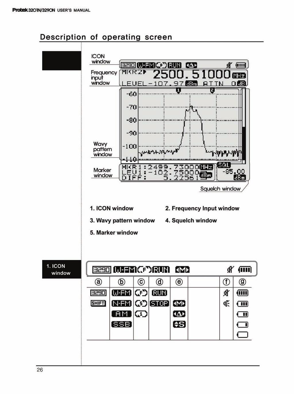
26 Display
27 Description of operating screen a Shift State Indication, Normal state Shift Input state Icons are changed by shift key b Reception Mode State Indication Wide Frequency Multi Mode Narrow Frequency Multi Mode Amplitude Modulation Mode Single side band Multi Mode Icons are changed by Mode key c Sweep Mode State Indication Free Run Squelch Run Single Run Icons are changed by Sweep key d Run-Scanning Run/Stop State Indication Running Stop Icons are changed by Run key e Marker State Indication None Center Marker State Marker 1 State Delta Marker State Marker 1, 2 Squelch Marker State Icons are changed by Marker key 27
28 3201N/3290N USER S MANUAL Description of operating screen f Buzzer On/off Indication Buzzer Off Buzzer On Icons are changed by Dot(Buzzer) key g Battery Residual Indication Full Empty 2. Frequency Input window a Frequency Value Indication e LEVEL b c ATTN d 28
29 Description of operating scene a Center Frequency Indication NONE Maker 1 Frequency Indication Maker 2 Frequency Indication Frequency Counter Value Indication - Indication of Frequency Value of each Mode b Level Value Indication Indication of Level Value of each Mode.. c Level Unit Can be established in Menu. [Please refer to Menu Level Unit establishment for further details] d Atten. Establish Value Indicate established Atten. Value. (Internal + External Atten. Value) [Please refer to Menu Level Unit establishment for further details] e Frequency Unit Every Frequency Unit is indicated in MHz 29
30 3201N/3290N USER S MANUAL Description of operating screen 3. Wavy pattern window a c b a b Indication Reference Value of Screen Level Value Resolution of Screen Level Value Indication to Vertical Level Value of Wavy pattern window. [Please refer to Screen Level establishment in Basic operation Explanation for further details] c Center Marker Marker 1 Marker 2 Marker Indication Every Marker can control the Up/Down keys or Knob Key. 30 Test Equipment Depot Washington Street Melrose, MA FAX TestEquipmentDepot.com

31 Description of operating screen 4. Marker Window a Center Marker, Marker 1, When Squelch Marker CENT SPAN STEP Center Frequency Span Frequency Step Frequency MHz b When Delta Marker MKR1 Marker 1 Frequency MHz LEV1 DIFF Marker 2 Level Value Marker1- Marker2 Level Value dbm 31
32 3201N/3290N USER S MANUAL Reception Mode Reception Mode is total (4) fourth mode as Demodulation when will receive. Wide-FM Narrow-FM AM SSB Wide Frequency Modulation Wide FM RBW(Resolution Bandwidth ) 180 khz Narrow Frequency Modulation Narrow RBW(Resolution Bandwidth ) 12.5 khz Amplitude Modulation SSB /AM RBW(Resolution Bandwidth ) 2.4 khz Single Side Band Modulation SSB /AM RBW(Resolution Bandwidth ) 2.4 khz Wide FM should be used to interpret a large Signal of Band width, Narrow FM should be used to interpret a narrow Bandwidth Signal. AM and SSB can used irrespective of Bandwidth. Push Mode (MHz) Key to establish the reception mode and then the top-left ICON will be changed to WFM, NFM, AM, SSB order. When inputting Frequency like Start/Stop, Span etc, the Mode (MHz) Key is used. RBW is fixed in each Mode as follows. Wide FM RBW (Resolution Bandwidth) 180 khz Narrow RBW (Resolution Bandwidth) 12.5 khz SSB/AM RBW (Resolution Bandwidth) 2.4 khz Reception Mode Establishment STEP 1 - Push the Mode (MHz) Key. STEP 2 - Push the Mode (MHz) Key and t the top left ICON will change to WFM, NFM, AM and SSB order. 32
33 Sweep Mode Sweep Mode is used to set up operation characters which interpret Input. Every each operation character is same as follows. Free Run Analyzing execution consecutively Single Run Only 1 time Execution Squelch Run Run by higher than Squelch level (Similar Trigger Mode of Oscilloscope) Establish this mode by pushing the Sweep (khz) Key and then the top left ICON will be changed to FREE Run, SQUELCH Run and SINGLE Run order. The Sweep (khz) Key is used as input Start/Stop, Span and Input Frequency Unit into khz Unit. After input is finished Frequency, FREE Run continues to execute Run-Scanning operation automatically. Squelch Run operation will stop Run-Scanning in case of Signal Level Value is getting higher than Squelch Level Value. But, If Signal Level is getting lower than Squelch Level, restart to Run- Scanning. After input is finished Start/Stop Frequency, Single Run execute Run-Scanning just a once. In addition, if it is desired to Run-Scanning, push the Run (GHz) Key and then execute Run-Scanning once Sweep Mode Establishment STEP 1 - Push the Sweep (khz) Key STEP 2 - Push the Sweep (khz) Key, and the top-left ICON will be changed to FREE Run, SQUELCH Run and SINGLE Run order. 33
34 3201N/3290N USER S MANUAL Set up Span The span is able to be set 1MHz to 400MHz. It has two settings 1MHz step up to 20MHz and 20MHz step from 20MHz to 400MHz. If other numeral keys than MHz unit key is pushed, the input unit will be set to the nearest times by rising automatically. Ex 1) When span input is 9.25Mhz, span will be 10MHz. Ex 2) When span input is 48MHz, span will be 60MHz. First, push the Shift Key (Shift icon is upside-down) in order to set up Span. The top-left ICON is changed, to. After that, push the No. Key. So then Frequency Input window changes the Span Input State. Enter the Input Frequency and then input the Unit to use for this Run (GHz), Mode(MHz) or Sweep (khz) Key would be set up Span. Regardless of Frequency Input State, upper Keys are only used the input units. Set up Span Mode STEP 1 - Push the Shift Key STEP 2 - Push the No. 2 Key - When the Sweep (khz) Key is pressed, the top-left ICON is changed to FREE Run, SQUELCH Run and SINGLE Run order. 34
35 Frequency Input Chosen Reception Mode, Sweep Mode and Span are showed on the top center of LCD. At first, choose Reception Mode and Sweep Mode to get a sense of the Frequency Bandwidth and a specific feel for analyzing. Choosing Frequency Value is a way to inputting Center and Start/Stop Frequency. To order to input Center Frequency just pushes the numeral keys. Press the key when Frequency Input Window is a CENT state. Push the Shift Push the Shift Key to input Start/Stop Frequency. Key to input Frequency you would like to analyze. Push the No. 1(Start/Stop) Frequency Input Window. Key, to inputted Start Frequency in Input Frequency by using the No. 0 to 9 Keys, Dot (Buzzer) Key, MARKER (DEL) Key and Run (GHz) as Unit Input Key, Mode (MHz) and SWEEP (khz) Key. Execution will be done automatically, after inputting the last Unit in the Frequency, according to a given Sweep Mode of Run-Scanning Mode. If the mode is Single Run, push the Run (GHz) Key and then execute Run-Scanning again. A wrong inputting content can be erased by using the MARKER (DEL) Key. The MARKER (DEL) space on PC Key operates like the Back Inputting Frequency in out of Frequency Input Mode: Frequencies can be deleted by pushing the MARKER (DEL) Key several times. Erase inputted Frequency and then push the Marker (DEL) Key one more time, you are now out of Frequency Input Mode. 35
36 Center Frequency Input Start/Stop Frequency Input
37 Adjust screen Level Settle Top Level- Reference Level and Level Resolution to be Display on scene. RLEV is an abbreviation of Reference Level. Choose through the Up/Down Keys and establish to use the Enter Key. Top Level in verticality axis would be changed established Value. DIFF is an abbreviation of Difference. Choose through the Up/Down Keys and establish to use the Enter Key. Level Step in verticality axis would be changed established Value RLEV DIFF Choose through the Up/Down the Enter Key. Choose through the Up/Down the Enter Key. Keys and push Keys and push DIFF 37
38 3201N/3290N USER S MANUAL Run-Scanning Run-Scanning is a process interpreting Frequency according to established Frequency Bandwidth and Span. And Run- scanning processes operate by establishing Sweep Mode Run-Scanning process would be accomplished by establishing Reception Mode and Sweep Mode (See above) 38

39 Marker Protek 3201N/3290N has Center Marker, Marker 1, Delta Marker (Marker1 and Marker2) and Squelch Marker. Each Marker Mode can define a state of Marker ICON into the top-left Marker Mode ICON. Marker Mode ICON Marker ICON Center Marker No ICON Marker 1 You can settle Marker 1 in this state. Marker 2 You can settle Marker 2 in this state. Squelch Marker Fix the volume when listening by making a multiple Signal to audible Frequency Bandwidth to use FM/AM/SSB and then fix Basic Signal of Squelch Run. 39
40 3201N/3290N USER S MANUAL Marker Center Marker Center Marker is not a Mode the user will choose when using Mark Mode in Basic operation. When inputting Start Frequency and Stop Frequency, Center Frequency information will appear automatically. The state is not indicated on the Mode ICON is Center Mode. Frequency and Level on Center Frequency will be indicated on Frequency Input Window. 40 Test Equipment Depot Washington Street Melrose, MA FAX TestEquipmentDepot.com

41 Marker Marker 1 To use Marker 1, press the Marker(DEL) key in Center Marker status. When it turns to Marker 1 mode, Marker mode icon is changed to. And frequency input window is changed to Center Marker to Marker 1. To move the Marker 1, use the Up/Down keys, or the Knob key. Then the frequency value and level value are displayed on frequency input window STEP 1 - Press the Marker (DEL) Key. - Check the Marker 1 mode in display window STEP 2 - To move the Marker 1 to wanted plot point, please use the Up/Down keys, or Knob key. - Then the frequency value and level value are displayed in the frequency input window 41

42 3201N/3290N USER S MANUAL Marker Delta Marker Press the Marker (DEL) Key until the Marker mode icon is changed to Delta Marker in the display window. And in this case, Marker 2 is added. The Marker mode is the total four modes. And the changed order of Marker mode is as below: Center Marker 1 Delta Maker Squelch Marker To handle the Marker 1, user can set up the marker 1 in Marker mode 1 To handle the Marker 2, user can set up the marker 2 in Delta Marker When user set up the Delta Marker, the frequency value and level value of Marker 2 are displayed in the frequency input window. The frequency value and level value of Marker 1, and the difference level value between Marker 1 and Marker 2 are displayed in the Marker window 42
43 Marker STEP 1 - Press the Marker (DEL) Key. - Check the Delta Marker mode in the display window STEP 2 - To move the Marker 1 to wanted plot point, please use the Up/Down keys, or Knob key. - Then, the frequency value and level value of Marker 2 are displayed in the frequency input window. The frequency value and level value of Marker 1, and the difference level value between Marker 1 and Marker 2 are displayed in the Marker window. Then the frequency value and level value are displayed in the frequency input window 43
44 3201N/3290N USER S MANUAL Marker Squelch Marker To know the magnitude of frequency, user can use the Squelch Marker. And the Squelch Marker is the right Marker on the vertical axis of the display window. Also, user can set up the Squelch Marker for setting the Squelch Level of Sweep mode and speaker output for a larger signal than Squelch Level through modulation for audio frequency range. (Modulation: Frequency modulation, Amplitude modulation, and SSB Modulation) User can hear the radio using upper method. Press the Marker (DEL) changed to the Squelch Marker Key until the Marker mode icon is in the display window. 44
45 Marker STEP 1 - Press the Marker key. - Check the Squelch Marker mode. STEP 2 - Move the Squelch Marker to wanted point using the Up/Down Keys or Knob Key. - The squelch value is displayed in the lower right display window. 45
46 3201N/3290N USER S MANUAL Power Meter Single Power Meter Function To use the Single Power Meter Function, at first push the Shift and then check the icon that is changed. Please push the numeral 4(Single) key. After inputting the frequency to measure, input the unit. STEP 1 - Push the Shift Key. STEP 2 - Push the NO.4(SINGLE) Key. STEP 3 - Input the frequency to measure.. STEP 4 - Input the units using RUN, Mode and Sweep keys. 46
 key.")
47 Power Meter Multi Power Meter Fuction To use the Multi Power Meter Function, at first push the Shift and then check the icon that is changed. key Please push the No. 5(MULTI) key. Assign any number of frequencies to measure within 1 to 9. After inputting the frequency to measure, input the unit. STEP 1 - Push the Shift Key. STEP 2 - Push the No.5 (MULTI) key. STEP 3 - Input a number within 1 to 9 STEP 4 - Input frequency to measure. STEP 5 - Input the units using RUN, Mode and Sweep keys. 47
 key.")
48 3201N/3290N USER S MANUAL UNIT UNIT Change Function STEP 1 - Push the Shift Key. STEP 2 - Push the No.6 (UNIT) key. STEP 3 - Using the Up/Down Key or knob key, move to the measuring unit and then set up by Enter key. 48
49 Setting of Attenuator Setting for Internal or External Attenuator The internal attenuator is used for maximum input signal -45dBm with Menu function. To set the internal attenuator, press the Shift key to change the upper right icon, to. And press the No. 9 (ATTN) key. To adjust the value of internal attenuator, press the Up/Down Keys or rotate the Knob key. And Press the Enter key. If the input signal is larger than -20dBm (ex. -10dBm, 0dBm, and etc), user can use the user s external attenuator. Setting of the EXT. ATTEN. is as below Push the No. 9(ATTN) key. INT. ATTEN in system is set up. Push the Dot key and then move the previous menu. After selecting the EXT ATTEN using the Up/Down Keys or rotate the Knob key, push the Enter key. After selecting requested ATTEN using the Up/Down Keys or rotate the Knob key, push the Enter key 49
50 3201N/3290N USER S MANUAL LCD Light The LCD Light is designed to ease the use of the instrument in a dark location. Press the Shift key to change the upper right icon, to. And press the No. 7 (LCD Light) key. *The Power ON/OFF of the LCD Light is toggle STEP 1 - Press the Shift key STEP 2 - Press the No. 7 (LCD Light) key If the LCD light is ON, the current of battery is relatively larger than when LCD light OFF. In other words using time of system is shorter 50 Test Equipment Depot Washington Street Melrose, MA FAX TestEquipmentDepot.com

51 LCD Contrast The function of LCD contrast is to adjust the contrast for the remained battery capacity. Push the Shift key to change the upper right icon, to. And push the No. 8 (LCD Contrast) key. The LCD contrast is adjusted by using the Up/Down keys or Knob key. And push the Enter key. STEP 1 - Press the Shift key STEP 2 - Press the No. 8 (LCD Contrast) key STEP 3 - To adjust the LCD contrast, use the Up/Down keys or Knob key and press the Enter key 51
52 3201N/3290N USER S MANUAL Buzzer ON/OFF User can set the Buzzer ON/OFF (Toggle ON/OFF) Push the Shift Key. Then the Icon, of left upper window is changed to shift icon. And press the Dot Key. And press the Dot Key. STEP 1 - Press the Shift key STEP 2 - Press the Dot Key 52
53 Save/Load The function of Save/Load is for the Waveform and Setup Statuses. The function of Save is for concurrently saving the Waveform and Setup Status in memory. And the saved Setup Status in memory includes the following information: Reception mode, Sweep mode, Frequency range, Step value, and Span value. User can use this with Menu or Multi key. The function of Load is for loading the saved Waveform and Setup Status in memory. If user only wants the Setup Status, please load the saved file for desired Setup Status. And press the Run key. Then this measuring instrument will complete the Run-scanning operation. User can only use this in Menu. The function of Delete is for deleting the saved file. Also User can only use this in the Menu. Save 53
54 3201N/3290N USER S MANUAL Save/Load STEP 1 - Press the Shift key STEP 2 - Press the Enter key STEP 3 - To save the waveform or setup status, a name with at least 7 characters is required. - To select the first character. Use the Up/Down keys. And press the Enter key - If want to save the file name fewer than 10 characters, press the END on stated inputted file name. STEP 4 - To delete the character, press the Marker key STEP 5 - When all 7 characters included blank are typed, press the Enter key. Then, output message for SAVE OK is displayed. SAVE OK - If user does not type the all 7 characters included blank, the function of save is not completed STEP 6 - To cancel the Save, press the Marker key until the first character is deleted. And additionally press the Marker key one time. - Then the Save is canceled and the output message is displayed as below. SAVE FAILED - The values to be saved are signal and system setting values. Buzzer, LCD contrast and LCD light states are not saved. 54
55 Save/Load Load STEP 1 - Press the Shift key STEP 2 - Press the Enter key STEP 3 - To save the waveform or setup status, a name with at least 7 characters is required. - To select the first character. Use the Up/Down keys. And press the Enter key The function of Load is to load the saved waveform and setup status. If user only wants to load only setup status, load the user s saved data and press the Run key. Then system will run in loading setup status. (Run-scanning) 55
56 3201N/3290N USER S MANUAL Save/Load Delete STEP 1 - Press the Menu key STEP 2 - To select the DELETE, use the Up/Down keys or Knob key and press the Enter key STEP 3 - To delete the saved data, select the user s saved data using the Up/Down keys or Knob key. And press the Enter key. Then the saved data will be deleted 56
57 Frequency Counter Select the F.counter under Main Menu function The input connector for the frequency counter is BNC connector. When the input level is inputted into the Frequency Counter, the measured frequency value is displayed in the frequency input window Input level is same as below. 35 MHz to 2,000 MHz : 150m Vrms 20 MHz to 1,000 MHz : 100m Vrms 2,000 MHz to 2,900 MHz : 400m Vrms 57
58 3201N/3290N USER S MANUAL Frequency Counter STEP 1 - Press the Menu key STEP 2 - To select the FUCTION, use the Up/Down keys or Knob key and press the Enter - Then sub menu is opened. key. STEP 3 - To select the F. COUNTER (Frequency Counter), use the Up/Down keys or Knob key and press the Enter key STEP 4 - The icon is displayed from the other icon. The FCNT is displayed in the frequency input window STEP 5 - When the input level is inputted in the Frequency Counter using BNC connector, the measured frequency value is displayed in the frequency input window STEP 6 - To change the Frequency Counter mode to Spectrum mode, run the upper Step 1 to Step 3. At this time, select the SPECTRUM not F. COUNTER in Step 3 58
59 Power Source Checking for Battery To check the battery s remained capacity Battery, user can refer to the battery icon in the upper area of display window How to use and replace the battery The power system of Protek 7830 uses the Ni-MH rechargeable batteries. Then, the power system supports fast charging. The charger for the Ni-MH batteries is controlled by the voltage and temperature of the battery cells. The Ni-MH rechargeable batteries must be used for the safe and stable power source. And if the charging is required, please avoid the site with high temperature or high humidity 59
60 3201N/3290N USER S MANUAL Level Unit Setting of the Unit The setting for level unit can be set up in the Menu. The level unit can be set up as below dbm dbuv dbmv STEP 1 - Push the Menu key STEP 2 - To select the LEVEL UNIT, use the Up/Down keys or Knob key and push the Enter Then sub menu is opened. key. STEP 3 - To select the user s wanted level unit, use the Up/Down keys or Knob key and push the Enter key 60 Test Equipment Depot Washington Street Melrose, MA FAX TestEquipmentDepot.com
61 Reset The function of Reset is for initializing the memory or system. The three kinds of resets are supported. And these resets are run through the Menu Preset System Reboot for initial setup status. (Center Frequency, Span Frequency, Marker and etc) Memory CLR The user s saved data will be cleared. (Memory Cleared) System INIT The upper two resets (PRESET and MEMORY CLR) are run. Then, system reboot for initial setup status and the user s saved data will be cleared STEP 1 - Push the Menu key STEP 2 - To select the RESET, use the Up/Down keys or Knob key and push the Enter - Then, sub menu is opened. key. STEP 3 - To run the wanted Reset, use the Up/Down keys or Knob key and push the Enter key. - Then, the selected reset will be run 61
62 3201N/3290N USER S MANUAL Baud Rate Setting of the Baud Rate The setting of the baud rate is for the transmission speed. The Baud Rate between PC and system is same as below. 115,200 BPS (Default) 57,600 BPS 38,400 BPS 19,200 BPS 9,600 BPS 4,800 BPS STEP 1 - Push the Menu key STEP 2 - To select the BAUD RATE, use the Up/Down keys or Knob key and push the Enter Then, sub menu is opened. key. STEP 3 - To select the wanted baud rate value, use the Up/Down keys or Knob key and push the Enter key 62
63 Connection for PC Setting of the Connection for PC The function of CONNECT PC is for connecting to a PC. First, the GUI program is run on the PC. And the serial cable is connected between PC and Protek Next, run the REMOTE PC from Menu. NONE REMOTE PC STEP 1 - Press the Menu key STEP 2 - To select the CONNECT PC, use the Up/Down keys or Knob key and press the Enter Then, sub menu is opened. key. STEP 3 - To select the REMOTE PC, use the Up/Down keys or Knob key and press the Enter key. Then, the connection between the PC and the system is running. 63
64 3201N/3290N USER S MANUAL Auto Power The Auto Power function should be used to conserve system power. When the power OFF time is enabled ( NONE is not selected), the power source will be turned off automatically if the user dose not use the system for the auto power OFF period of time. The auto power OFF time is same as below NONE 05MINUTES 10MINUTES 20MINUTES 30MINUTES STEP 1 - Push the Menu key twice STEP 2 - To select the AUTO POWER, use the Up/Down keys or Knob key and push the Enter Then, sub menu is opened. key. STEP 3 - To select the auto power time, use the Up/Down keys or Knob key and push the Enter key 64
65 Offset Level Offset compensates for any loss due to the cabling. Offset adds the value of +Offset to all values of measurement. STEP 1 - Press the Menu key twice STEP 2 - Move the cursor on PC Connect using the Up/Down Keys or knob Key. STEP 3 - Push the Enter Key and then move the submenu. - Move the db value of Offset. - Push the Enter Key STEP 4 - Push the Menu Key one more time to exit the System 65
66 3201N/3290N USER S MANUAL Menu There are two modes. One is Multi key function with the Shift and the other is to select other functions. It can select the functions using multi key and in Menu. The functions that could be selected in Menu mode is as blow Key Level Unit Reset Band Rate Connect PC To exit from Menu or System, push the Menu Key or push the Dot key. These keys will move through the menu either lower or higher. 66
67 Menu STEP 1 - Push the Menu key twice STEP 2 - To select wanted function, use the Up/Down Keys or the Knob Key. STEP 3 - Push the Enter Key STEP 4 - After selecting function of lower item or On/Off, push the Enter Key STEP 5 - Exit the Menu after pushing the Menu Key twice. - When the Menu Key is pushed one time, you are in System 67
68 3201N/3290N USER S MANUAL Menu Function Reception Mode Sweep Mode Marker Save Load Level Unit Spectrum Frequency Counter TEST Mode Single Power Meter Multi Power Meter N-FM W-FM SSB AM Free Run Squelch Run Single Run None Marker Delta MKR Squelch MKR Save Data Load Data dbm dbuv dbmv Set up the functions of Spectrum and frequency counter. Set up the Reception Mode. It s possible to set up with the Shift Key (Shift button is upside-down please check all buttons to confirm they are correct.) Set up the Sweep Mode. It could be set up with the Shift Key. Marker or function using the Marker. The mode can be set up with the Shift Key. The mode can be set up with the Shift Key. The mode can be set up with the Shift Key. 68
69 Menu Reset Band Rate Connect PC Pre Reset Memory CLR System INI 115,200 BPS 57,600 BPS 38,400 BPS 19,200 BPS 9,600 BPS 4,800 BPS None Remote PC Restarting the System and clear all parameters for set up Delete the stored data All Reset restarting the system and delete the stored data Select the speed of serial communication between the unit and PC Select the connection to PC 69

70 3201N/3290N USER S MANUAL System There are modes that select the function of Multi key using the Shift Key and the other functions. Functions can be selected using the multi key and the Menu. The functions that can be selected in Menu mode are as blow. To exit from Menu or System, push the Key or push the Dot key, this will move you to lower menu items or to higher menu items. 70 Test Equipment Depot Washington Street Melrose, MA FAX TestEquipmentDepot.com
71 System STEP 1 - Press the Menu Key STEP 2 - Press the Menu Key once more. STEP 3 - To select desired function, use the Up/Down Keys or the Knob Key STEP 4 - Press the Enter Key STEP 5 - After selecting a lower item function or On/Off, push the Enter Key STEP 6 - Push the Menu Key once to exit the System 71
72 3201N/3290N USER S MANUAL System Auto Power Buzzer LCD Light None 05 Minutes 10 Minutes 20 Minutes 30 Minutes ON OFF ON OFF Select auto power saving mode. Select Buzzer On/Off. It could be set up with the Shift Key (Shift Key Icon is upside down. Please check all icons to fix this.) Select LCD Light On/Off. It could be set up with the Shift Key. LCD Contrast 1 to 10 Step INT. Atten. EXT. Atten. 0 db 10 db 20 db 30 db 35 db 0 db to 90 db Offset db to 99.0 db Default save SAVE During booting, save default value to be applied. When Saving the values, all values will be saved except Signal. 72
73 Description of key operating 6 Run [GHz] Instruction to start scanning frequencies After power on, this button will work as it did under the most recent setup, or when Squelch Run functions are active. or Single Run [Please refer to the Scan in description of basic operation details if needed] Units input function can be used to set up Start/ Stop/ Scan/ Center frequencies. After inputting the frequency values, push the k GHz key to view the units. Mode [MHz] Selecting Reception Mode The following Reception Modes can be selected WFM, NFM,AM and SSB. [Please refer to the Reception Mode section for detailed description of basic operation.] Units can be entered when setting up Start/Stop/Scan/Center frequencies. Push the MHz key after inputting the frequencies to view the values. 73
74 3201N/3290N USER S MANUAL Sweep [khz] Selecting Sweep Mode This button selects the Sweep Mode such as FREE Run, SQUELCH Run and SINGLE Run [Please refer to the Sweep Mode section for a detailed description of basic operation.] The units input function can be used to set up Start/ Stop/ Scan/ Center frequencies. After input the value of frequency, push the key of khz for the units its. Marker [DEL] Selecting Marker functions. After pushing this button, please select Marker functions such as Center Marker, Marker 1, Delta Marker and Squelch Marker. [Please refer to the Marker section for a description of basic operation for more detail.] This is the Delete function when setting up Start/Stop/Scan/Center frequencies. When inputting the frequency values, the Marker used as the Delete Key. Key can be This key functions as a backspace key on a PC. 74
75 No. 1 [Start/Stop] Press the No. 1 key to input the value of 1. To input the value of numeral 1 in the Start/Stop/Scan/Center frequencies, please use the No. 1 Key. Pressing No, 1 key and the Shift Input function for Start/Stop Mode. Key will active the Select the Start/Stop Mode by pushing the Shift Key and than push the numeral Key. [Please refer to the Frequency Input section for a description of basic operation if more detail is needed.]. No. 2 [Span] Press the No. 2 key to input the value of 2. Input the value of numeral 2 in the Start/Stop/Scan/Center Mode by pressing the No. 2 Key. Span Frequency Input function can be activated by pushing Shift Key By pushing the Shift Key and than pushing the No. 2 Key, the Span Mode can be activated. [Please refer to the Span section for a detailed description of basic operation if required.] 75
76 3201N/3290N USER S MANUAL No. 3 [Level] Push the No. 3 key to input the value of 3. In order to input the value of numeral 3 in the Start/Stop/Scan/Center frequencies, push the No. 3 Key. Display Level Adjustment Function by pushing Shift Key. On pushing the Shift Key and then push the No. 3 Key, Basic Level of vertical axis and Level Step on display could be adjusted. [Please refer to the Display Level Adjustment section for a detailed description of basic operation if need.] No. 4 [SINGLE] Push the No. 4 key to input the value of 4. In order to input the value of numeral 4 in the Start/Stop/Scan/Center frequencies, push the No. 4 Key. Single Power Meter Adjustment Function by pushing Shift Key After pushing the Shift key on, if No. 4 key is pushed, Single Power Meter function will be selected. [Please refer to the section for Single Power Meter using the Power Meter for detailed description of basic operation if needed.] 76
77 No. 5 [MULTI] Push the No. 5 key to input the value of 5. Push the No. 5 Key to input the value of numeral 5 in the Start/ Stop /Scan/ Center frequencies. Multi Power Meter Adjustment Function after pushing Shift Key On pushing the Shift key and then pushing the No. 5 key is pushed, Multi Power Meter function can be selected [Please refer to the Multi Power Meter section for a details description for using the Power Meter if needed.] No. 6 [UNIT] Push the No. 6 key to input the value of 6. The No. 6 Key is used to input the value of numeral 6 in the Start/Stop/Scan/Center frequencies. Level Unit Adjustment Function after pushing Shift Key By pushing the Shift key and then pushing No.6 key, Level Unit function can be selected. [Please refer to the Level Unit section for a detailed description of basic operation if needed.] 77
78 3201N/3290N USER S MANUAL No. 7 [LCD Light] Push the No. 7 key to input the value of 7. When inputting the value of numeral 7 in the Start/Stop/Scan/Center frequencies, the No. 7 Key is used LCD Light Function after pushing the Shift Key By pushing the Shift key and then pushing the No. 7 Key, LCD Light function can be selected. [Please refer to the LCD Light section for details about basic operation if needed.] No. 8 [LCD CONT; LCD Contrast] Push the No. 8 key to input the value of 8. To input the value of numeral 8 in the Start/Stop/Scan/Center frequencies, the No. 8 Key is used. LCD Contrast Function after pushing the Shift Key By pushing the Shift key and then pushing the No. 8 Key, LCD Contrast function can be selected. [Please refer to the LCD Contrast section for details on basic operation.] 78
79 No. 9 [Attenuator] Push the No. 9 key to input the value of 9. To input the value of numeral 9 in the Start/Stop/Scan/Center frequencies, the No. 9 Key is used Attenuator Setup Function after pushing the Shift Key By pushing the Shift key and then pushing the No. 9 Key, Attenuator function can be selected. [Please refer to the Attenuator Setup section for details about basic operation.] No. 0 [System] Push the No. 0 key to input the value of 0. When inputting the value of numeral 0 in the Start/Stop/Scan/Center frequencies, the No. 0 Key is used. System Setup Function after pushing the Shift Key By pushing the Shift key and then pushing the No. 0 Key, System Setup function can be selected. [Please refer to the System Setup section for details about basic operation.] 79
80 3201N/3290N USER S MANUAL Shift Using the Function Key The Shift Key dose not performs any function by itself. The Shift Key can be used with functions printed below the numeral keys. If the shift key is pressed twice, CENT/SPAN located on bottom of display is changed to START/STOP. Dot [Buzzer] The Dot key should be used to input a decimal point When input the value of Decimal Point in the Start/Stop/Scan/Center frequencies, this key is used. Buzzer Setup Function after pushing the Shift Key By pushing the Shift key and then pushing the Dot Key, Buzzer On or OFF can be selected. [Please refer to the Buzzer section for details on basic operation.] Return Function on Menu and System Return Function is used to return from lower Menu to higher Menu on Menu and System. 80 Test Equipment Depot Washington Street Melrose, MA FAX TestEquipmentDepot.com
5MHz FUNCTION GENERATOR
 5MHz FUNCTION GENERATOR MODEL GF-8056 99 Washington Street Melrose, MA 02176 Phone 781-665-1400 Toll Free 1-800-517-8431 Visit us at www.testequipmentdepot.com User s Manual Elenco TM Electronics, Inc.
Power Meter. Measurement Guide. for Anritsu RF and Microwave Handheld Instruments BTS Master Site Master Spectrum Master Cell Master
 Measurement Guide Power Meter for Anritsu RF and Microwave Handheld Instruments BTS Master Site Master Spectrum Master Cell Master Power Meter Option 29 High Accuracy Power Meter Option 19 Inline Peak
2.9GHz SPECTRUM ANALYZER
 2.9GHz SPECTRUM ANALYZER Introducing a new 2.9GHz Spectrum Analyzer Manufacturing Research and Development Field Service Education Powerful capacity by advanced digital synthesizer Revolutionary features
TV SIGNAL LEVEL METER USER MANUAL
 TV SIGNAL LEVEL METER USER MANUAL - 0 - 1. Overview (1) (1) RF input (2) (3) A D E B C (2) Speaker (3) LCD display (4) Charger indicator (5) RS232 communication port (6) DC-IN port F G A. The battery icon
DE1103 PLL FM STEREO/SW.MW.LW DUAL CONVERSION SYNTHESIZED WORLD RECEIVER OPERATION MANUAL
 DE1103 SYNTHESIZED WORLD RECEIVER SYNTHESIZED WORLD RECEIVER DE1103 OPERATION MANUAL INDEX POWER SUPPLY POWER SUPPLY... 1 POWER INDICATION... 3 BATTERY CHARGER... 4 BEFORE OPERATION..... 6 SET THE CLOCK...
Handheld 3.3GHz Spectrum Analyzer
 Handheld 3.3GHz Spectrum Analyzer Optimum for evaluation of W-CDMA CDMA GSM PDC PHS Wireless LAN Bluetooth 2650 1 FEATURES 2650 1 Compact and lightweight 3.75 lb (1.7 kg) The dimensions are as small as
I.D.A. Operation manual
 TRX-200 Wide ide Band Receiver Operation manual Thank you for purchasing the TRX-200 all modes wide band monitoring receiver. Please read this operating manual carefully to avoid miss operation of the
Introduction. Specifications. Features. Controls. Model 103
 Index Page # Model 103 2 Introduction 2 Specifications 2 Features 2 Controls 2 Hints and Tips 3 Input Sensitivity (typical) 3 RF Signal Strength Bargraph 3 Frequency Display Resolution 3 Model 104 4 Introduction
INDEX POWER SOURCES OPERATING ON BATTERY BATTERY REPLACEMENT
 INDEX SOURCES... 1 OPERATING ON BATTERY... 1 OPERATING ON AC ADAPTOR... INDICATION... 3 BATTERY... 3 CLOCK FUNCTION...4 SET THE CLOCK...4 SELECT TIME MODE...5 MW STEP 9K/10K SELECTION...5 TURN ON / OFF
JD723A/JD724B/JD726A Cable and Antenna Analyzers
 COMMUNICATIONS TEST & MEASUREMENT SOLUTIONS JD723A/JD724B/JD726A Cable and Antenna Analyzers Key Features Portable and lightweight handheld instrument. Built in wireless frequency bands as well as the
Signal Analysis Measurement Guide
 Signal Analysis Measurement Guide Agilent Technologies EMC Series Analyzers This guide documents firmware revision A.08.xx This manual provides documentation for the following instruments: E7401A (9 khz-
Handheld Spectrum Analyzer R&S FSH khz to 3 GHz
 Handheld Spectrum Analyzer R&S FSH3 100 khz to 3 GHz Spectrum analysis anywhere, anytime The R&S FSH3 is the ideal spectrum analyzer for rapid, high-precision, cost-effective signal investigations. It
Copyright X02827C00 - Ed. 1-04/16
 1 GHz Spectrum Analyzer Userr s manuall CHAUVIN-ARNOUX Test and Measurement Division Parc des Glaisins 6, avenue du Pré de Challes F - 74940 ANNECY-LE-VIEUX Tel. +33 (0)4.50.64.22.22 - Fax +33 (0)4.50.64.22.00
TECSUN PL-365. FM stereo / MW / SW-SSB DSP RECEIVER OPERATION MANUAL ELECTRONIC IND. LTD. RADIOS AUSTRALIA
 TECSUN TECSUN RADIOS AUSTRALIA PL-365 FM stereo / MW / SW-SSB DSP RECEIVER OPERATION MANUAL TECSUN PL-365 FM STEREO/MW/SW-SSB DSP RECEIVER TECSUN RADIOS TECSUN AUSTRALIA ELECTRONIC IND. LTD. PL-365 Functional
Dear Valued Customer,
 Dear Valued Customer, Thank you for choosing Listen! All of us at Listen are dedicated to provide you with the highest quality products available. We take great pride in their outstanding performance because
PAMS. User s Manual. Portable Attenuation Measurement System. The solution for making easy shielding effectiveness measurements.
 PAMS Portable Attenuation Measurement System User s Manual The solution for making easy shielding effectiveness measurements. 310-010042-001 TABLE OF CONTENTS Warranty Statement 1 Chapter 1 General Information
CIRCUIT-TEST ELECTRONICS
 USER'S MANUAL Sweep Function Generator with Counter SWF-8030 CIRCUIT-TEST ELECTRONICS www.circuittest.com TABLE OF CONTENTS SAFETY INFORMATION...page 3 INTRODUCTION... 4 SPECIFICATIONS... 5 FRONT PANEL
MINI HAND HELD TYPE 5 BANDS COMMUNICATIONS RECEIVER
 FR-100 MINI HAND HELD TYPE 5 BANDS COMMUNICATIONS RECEIVER USER'S OPERATION MANUAL CONTENTS PAGE DESCRIPTION OF FEATURES... 4 -DISPLAY PANEL FEATURES... 4 -TOP PANEL FEATURES... 5 -SIDE AND BACK PANEL
Site Master Cable and Antenna Analyzer with Spectrum Analyzer
 Maintenance Manual Site Master Cable and Antenna Analyzer with Spectrum Analyzer S331E, 2 MHz to 4 GHz S332E, 2 MHz to 4 GHz, Spectrum Analyzer, 100 khz to 4 GHz S361E, 2 MHz to 6 GHz S362E, 2 MHz to 6
Important safety instructions
 MMR-88 Version 1 Important safety instructions 1. 2. 3. 4. 5. 6. 7. 8. 9. Please read these instructions carefully. Please keep these instructions for future reference. Heed all warnings Follow all instructions
User Manual. ilive 2 Wireless microphone system
 User Manual ilive 2 Wireless microphone system Safety instructions When using this electronic device, basic precautions should always be taken, including the following: 1 Read all instructions before using
khz to 2.9 GHz Spectrum Analyzer
 Spectrum Analyzers 2399 9 khz to 2.9 GHz Spectrum Analyzer A spectrum analyzer with outstanding performance and a user friendly visual interface simplifying many complex measurements. 9 khz to 2.9 GHz
Dawson DDM190. Digital Multimeter User s Manual
 Dawson DDM190 Digital Multimeter User s Manual TABLE OF CONTENTS LIMITED WARRANTY AND LIMITATION OF LIABILITY... 3 Out of the Box... 3 Accessories.. Error! Bookmark not defined. Safety Information... 7
PLL SYNTHESIZED RECEIVER FM STEREO / MW / LW / SW-SSB / AIR BAND OPERATION MANUAL TECSUN PL-660. Shortwave BW
 PL-660 PLL SYNTHESIZED RECEIVER FM STEREO / MW / LW / SW-SSB / AIR BAND OPERATION MANUAL TECSUN Shortwave BW FAST khz SYNC USB PL-660 AM SYNCHRONOUS DETECTOR FM STEREO/LW/MW/SW-SSB/AIR PLL SYNTHESIZED
REDSUN PF2100 PLL RADIO OPERATING MANUAL
 REDSUN PF2100 PLL RADIO OPERATING MANUAL TRANSLATED BY LIYPN ALL RIGHTS RESERVED JUNE 2006 (We are the copyright holder of this manual in English. Please do NOT distribute this manual in any form nor post
Agilent N9343C Handheld Spectrum Analyzer (HSA)
") Test Equipment Depot - 800.517.8431-99 Washington Street Melrose, MA 02176 - TestEquipmentDepot.com Agilent N9343C Handheld Spectrum Analyzer (HSA) 1 MHz to 13.6 GHz (tunable to 9 khz) Data Sheet Field
Test Equipment Depot - 800.517.8431-99 Washington Street Melrose, MA 02176 - TestEquipmentDepot.com Agilent N9343C Handheld Spectrum Analyzer (HSA) 1 MHz to 13.6 GHz (tunable to 9 khz) Data Sheet Field
Four Carrier Signal Generator Operation Manual
 ACE 5400 Four Carrier Signal Generator Operation Manual Table of Contents 1. Features...2 1.1. Specifications...3 1.2. Connections...3 1.3. Controls and Connections...4 1.4. Keypad...4 2. Operating Modes...5
Assistive Listening Systems. RX-6 User s Guide
 Assistive Listening Systems RX-6 User s Guide Page ii RX-6 User s Guide Copyright Information Contents Introduction 1 Controls 2 Installing Batteries 3 Operation 3 Tuning the RX-6 4 Changing Preset Channels
2801 Multilock. Communications System Analyzer. Data Sheet. Boosting wireless efficiency
 Data Sheet 2801 Multilock Communications System Analyzer Boosting wireless efficiency A real multi-talented instrument the Willtek 2801 Multilock The Willtek 2801 Multilock is a test instrument for multiple
S5101 Handheld Radio Communication Analyzer
 is the ideal radio tester for laboratory, production, service and maintenance use. It combines radio frequency emission, reception analysis, audio source, analyzer, etc. all into one unit. It can measure
User s Guide ASSISTIVE LISTENING SYSTEMS
 User s Guide ASSISTIVE LISTENING SYSTEMS 2 Digital-1 User s Guide Contents How to use Digital-1...3 Tuning...6 Frequency Chart...8 Correcting Interference...9 Recharging...10 Specifications...12 Notice...13
DIGIAIR PRO USER MANUAL
 DIGIAIR PRO USER MANUAL Content: DIGIAIR PRO Description 2 1 GETTING STARTED 3 1.1 POWER ON/OFF 3 1.2 POWER SUPPLY AND BATTERY 3 1.3 HOW TO USE THE METER 3 1.4 ATTENUATOR 4 2 DESCRIPTION OF THE FUNCTIONS
Spectrum Analyzers. 2394A 1 khz to 13.2 GHz Spectrum Analyzer.
 Spectrum Analyzers 2394A 1 khz to 13.2 GHz Spectrum Analyzer A spectrum analyzer with outstanding performance and a user friendly visual interface simplifying many complex measurements 1 khz to 13.2 GHz
Register your product and get support at AE5430. EN User manual
 Register your product and get support at www.philips.com/welcome AE5430 User manual Concents 1 Important 4 Hearing Safety 4 English 2 Your FM/DAB+ radio 5 Introduction 5 What s in the box 5 Overview of
DT-800 中文 GB. Version 1
 DT-800 中文 GB Version 1 1. 2. 3. 4. 5. 6. 7. 8. 9. Important safety instructions Read and understand all safety and operating instructions before the radio is operated. Retain instructions: The safety and
FREEDOM Communications System Analyzer R8000C DATA SHEET
 FREEDOM Communications System Analyzer R8000C DATA SHEET Table of Contents Operating/Display Modes General 3 3 Generator (Receiver Test) 4 Receiver (Transmitter Test) 5 Spectrum Analyzer 6 Oscilloscope
WORLD BAND RADIO. AM/FM/SW/L W/AIR Band /SSB radio with LCD backlight OWNER S MANUAL
 WORLD BAND RADIO AM/FM/SW/L W/AIR Band /SSB radio with LCD backlight display and keypad direct entry OWNER S MANUAL WARNING Do not expose this appliance to rain or moisture Do not submerge or expose to
Spectrum Analyzers 2680 Series Features & benefits
 Data Sheet Features & benefits n Frequency range: 9 khz to 2.1 or 3.2 GHz n High Sensitivity -161 dbm/hz displayed average noise level (DANL) n Low phase noise of -98 dbc/hz @ 10 khz offset n Low level
Important safety instructions
 RCR-29 GB Version 1 Important safety instructions VERY IMPORTANT PLEASE READ Sangean suggest that you keep your AC Adapter at least 12 inches away from the radio while listening to the AM Band. Your Sangean
khz to 2.7 GHz Spectrum Analyzer
 Spectrum Analyzers 2398 9 khz to 2.7 GHz Spectrum Analyzer A breakthrough in high performance spectrum analysis, combining cost effectiveness and portability in a new lightweight instrument 9 khz to 2.7
FREEDOM Communications System Analyzer R8100 DATA SHEET
 FREEDOM Communications System Analyzer R8100 DATA SHEET Table of Contents Operating/Display Modes 3 General 3 Generator (Receiver Test) 4 Receiver (Transmitter Test) 5 Spectrum Analyzer 6 Oscilloscope
FREEDOM Communications System Analyzer R8000C DATA SHEET
 FREEDOM Communications System Analyzer R8000C DATA SHEET Table of Contents Operating/Display Modes 3 General 3 Generator (Receiver Test) 4 Receiver (Transmitter Test) 5 Spectrum Analyzer 6 Oscilloscope
A 500 Broadband Power Amplifier
 A 500 Broadband Power Amplifier HIGH RF VOLTAGES MAY BE PRESENT AT THE OUTPUT OF THIS UNIT. All operating personnel should use extreme caution in handling these voltages and be thoroughly familiar with
2.7 GHz FREQUENCY COUNTER with TCXO
 2.7 GHz FREQUENCY COUNTER with TCXO TABLE OF CONTENTS 1. FEATURES... 1 2. SPECIFICATIONS... 1 2-1 General Specifications... 1 2-2 Table for Resolution & Sampling Time... 3 3. FRONT PANEL DESCRIPTION...4
310 DIVERSITY CAMERA-MOUNT UHF WIRELESS MICROPHONE SYSTEM
 310 DIVERSITY CAMERA-MOUNT UHF WIRELESS MICROPHONE SYSTEM 310UDR - 35BT - 35HT - 35XT INSTRUCTION MANUAL Thank you for purchasing the Azden 310 Diversity Wireless Microphone system. The components included
Micro-Ohmmeter Model UM200
 User's Guide 99 Washington Street Melrose, MA 02176 Phone 781-665-1400 Toll Free 1-800-517-8431 Visit us at www.testequipmentdepot.com Micro-Ohmmeter Model UM200 WARNING Do not use the ohmmeter before
CABLE TV ANALYZER PROMAX-5
 99 Washington Street Melrose, MA 02176 Fax 781-665-0780 TestEquipmentDepot.com INSTRUCTION MANUAL PROMAX-5 CABLE TV ANALYZER PROMAX-5 1 GENERAL INFORMATION 1.1 Description The PROMAX-5 is an advanced model
Handheld Spectrum Analyzer R&S FSH3
 Handheld Spectrum Analyzer R&S FSH3 100 khz to 3 GHz Fourth Edition July 2003i Spectrum analysis anywhere, anytime The R&S FSH3 is the ideal spectrum analyzer for rapid, high-precision, cost-effective
WE-525T Antenna Analyzer Manual and Specification
 WE-525T Antenna Analyzer Manual and Specification 1.0 Description This product is designed to speed and ease the testing and tuning of antenna systems. Graphical displays of SWR, Return loss, Distance
FREEDOM Communications System Analyzer R8100 DATA SHEET
 FREEDOM Communications System Analyzer R8100 DATA SHEET Table of Contents Operating/Display Modes General 3 3 Generator (Receiver Test) 4 Receiver (Transmitter Test) 5 Spectrum Analyzer 6 Oscilloscope
Handheld Spectrum Analyzer R&S FSH 3
 Handheld Spectrum Analyzer R&S FSH 3 100 khz to 3 GHz Fifth Edition December 2003i Spectrum analysis anywhere, anytime The R&S FSH3 is the ideal spectrum analyzer for rapid, high-precision, cost-effective
RX1300 MULTIBAND SCANNING RECEIVER INSTRUCTION MANUAL
 RX1300 MULTIBAND SCANNING RECEIVER INSTRUCTION MANUAL CAUTION Please read these instructions carefully before operating your receiver. Your scanner is a complex and powerful unit with many functions. Please
TECSUN TECSUN PL-680 PLL SYNTHESIZED RECEIVER FM STEREO / MW / LW / SW-SSB / AIR BAND OPERATION MANUAL TECSUN ELECTRONIC IND. LTD.
 TECSUN TECSUN PL-680 PLL SYNTHESIZED RECEIVER FM STEREO / MW / LW / SW-SSB / AIR BAND OPERATION MANUAL TECSUN ELECTRONIC IND. LTD. Address: Rm 11, 13/F, Block A, Hoi Luen Ind. Ctr., 55 Hoi Yuen Road, Kwun
Always there to help you. Register your product and get support at AJB4300. Question? Contact Philips.
 Always there to help you Register your product and get support at www.philips.com/support Question? Contact Philips AJB4300 User manual Contents 1 Important 2 Safety 2 2 Your FM/DAB+ clock radio 3 Introduction
Model S1365 Spectrum Analyzer. User Manual
 Model S1365 Spectrum Analyzer User Manual November 2018 Edition, Version 1.1.0 Copyright Corporation. All rights reserved. The products are under the protection of the patent rights, including ones which
Digiair Pro ATSC USER MANUAL
 Digiair Pro ATSC USER MANUAL Content: DIGIAIR PRO Description 2 1 GETTING STARTED 3 1.1 POWER ON/OFF 3 1.2 POWER SUPPLY AND BATTERY 3 1.3 HOW TO USE THE METER 3 ATTENUATOR 4 DIGITAL MODE 4 2 DESCRIPTION
free solo PT UHF wireless system user manual
 free solo PT UHF wireless system user manual Musikhaus Thomann e.k. Treppendorf 30 96138 Burgebrach Germany Telephone: +49 (0) 9546 9223-0 E-mail: info@thomann.de Internet: www.thomann.de 22.01.2013 Table
DEGEN DE1103 FM / MW / SW RECEIVER FM / AM / SSB / CW MODES OPERATING MANUAL
 DEGEN DE1103 FM / MW / SW RECEIVER FM / AM / SSB / CW MODES OPERATING MANUAL (1) Power/Sleep (2) Reset (3) Lock Key (4) Time/Delete (5) St./Mono/SSB LED (6) Stereo/Mono/SSB (7) FM Band/Station Search Backward
User Manual. Model MHz Dual Channel. True RMS Oscilloscope Datalogger
 99 Washington Street Melrose, MA 02176 Phone 781-665-1400 Toll Free 1-800-517-8431 User Manual Visit us at www.testequipmentdepot.com Back to the Extech 381395 Product Page Model 381395 5MHz Dual Channel
UHF Wireless Transmitter
 UHF Wireless Transmitter Model: EM-100 Diversity Wireless System for On Stage In-ear Monitor Table of Contents System Components...1 Transmitter Features...2 Receiver Features...4 System Setup...5 Specifications...7
FM Modulation. Accuracy. Total. Harmonics. Input Range. Frequency. Range. Deviation. Range. Modulation. Accuracy. Audio In Switchable Loads.
 Product Specification VIAVI 3550R Touch-Screen Radio Test System VIAVI Solutions General Specifications RF Signal Generator Output SSB Phase Noise 2 MHz - 1 GHz (usable from 500 khz) T/R Port: -50 to -125
Single Channel Radio Mic System USER MANUAL. WMU-116-H (Hand Held) WMU-116-B (Belt Pack) Single Channel Radio Mic System
 WMU-116-B (Belt Pack) Single Channel Radio Mic System") Single Channel Radio Mic System USER MANUAL WMU-116-H (Hand Held) WMU-116-B (Belt Pack) Single Channel Radio Mic System Welcome Thank you for choosing Hill Audio for your sound system. To make sure that
Single Channel Radio Mic System USER MANUAL WMU-116-H (Hand Held) WMU-116-B (Belt Pack) Single Channel Radio Mic System Welcome Thank you for choosing Hill Audio for your sound system. To make sure that
Digital Spectrum Analyzer GA40XX Series
 GA4062/GA4032 9kHz~1.5GHz GA4033/GA4063 9kHz~3GHz GA4064 9kHz~7.5GHz Product Overview GA40XX series is a small size, light weight, cost-effective portable spectrum analyzer to meet your all the RF application
PREMIUMAUDIOVIDEOLIGHTINGANDPOWERPRODUCTS
 FACTOR ELECTRONICS PREMIUMAUDIOVIDEOLIGHTINGANDPOWERPRODUCTS VT-1 / VT-4 Professional Tuners With RBDS Owners Manual Owners Manual IMPORTANT NOTE: THIS OWNER'S MANUAL IS PROVIDED AS AN INSTALLATION AND
IEM 100 UHF wireless system. user manual
 IEM 100 UHF wireless system user manual Musikhaus Thomann Thomann GmbH Hans-Thomann-Straße 1 96138 Burgebrach Germany Telephone: +49 (0) 9546 9223-0 E-mail: info@thomann.de Internet: www.thomann.de 18.06.2018,
TSC-100RA INSTRUCTION MANUAL. MULTIBAND SCANNING RECEIVER. Manufactured by
 MULTIBAND SCANNING RECEIVER Manufactured by www.ttikorea.co.kr CONTENTS. CAUTIONS.... SUPPLIED EQUIPMENT... 5. INSTALLING THE BATTERIES... 5. CONTROLS... 6 Power On/Off Lock Button... 7 Antenna... 7 Squelch
FREEDOM Communications System Analyzer R8600 DATA SHEET
 FREEDOM Communications System Analyzer R8600 DATA SHEET Table of Contents Operating/Display Modes 3 General 3 Generator (Receiver Test) 4 Receiver (Transmitter Test) 5 Spectrum Analyzer 6 Oscilloscope
DSP40. User Manual.
 DSP40 User Manual www.audac.eu ADDITIONAL INFORMATION This manual is put together with much care, and is as complete as could be on the publication date. However, updates on the specifications, functionality
RAKSA 120 SELECTIVE RF DETECTOR OWNER S MANUAL
 RAKSA 120 SELECTIVE RF DETECTOR OWNER S MANUAL Table of Contents 1. Introduction 6 2. Operating Principle 7 3. Operation Instructions 8 4. Battery Charging 9 5. ON/OFF and Operation 11 6. The Main Menu
5MHz FUNCTION GENERATOR
 5MHz FUNCTION GENERATOR MODEL GF-8056 User s Manual Elenco TM Electronics, Inc. Copyright 2004 by Elenco TM Electronics, Inc. All rights reserved. 753117 No part of this book shall be reproduced by any
ROBERTS. DAB / DAB+ / FM RDS digital portable radio. Please read this manual before use
 ROBERTS DAB / DAB+ / FM RDS digital portable radio Please read this manual before use Contents Controls... 2-3 Battery operation...4 Using the AC adaptor...5 Operating your radio - DAB...6 Selecting a
AX400 / AE 500 H First Edition Owner s Manual
 AX400 / AE 500 H First Edition Owner s Manual Thank you for purchasing our receiver For proper use of this receiver, please read this manual thoroughly. Keep this manual in a safe place for future reference.
DT-250 Instruction manual AM/FM stereo 2 bands PLL Synthesized Personal Radio
 DT-250 Instruction manual AM/FM stereo 2 bands PLL Synthesized Personal Radio Controls 1. Headphone/Antenna jack To improve FM reception during speaker use, leave headphones or external antenna device
ALAN 777 PMR 446 Radio Set User manual
 ALAN 777 PMR 446 Radio Set User manual The all new ALAN 777 represents the very latest and most advanced technology currently available on the PMR446 and LPD market. With its stylish lines and modern design,
Handheld Spectrum Analyzer R&S FSH3
 Handheld Spectrum Analyzer R&S FSH3 100 khz to 3 GHz Third Edition March 2003i Spectrum analysis anywhere, anytime The R&S FSH3 is the ideal spectrum analyzer for rapid, high-precision, cost-effective
IEM 200 R UHF receiver. user manual
 IEM 200 R UHF receiver user manual Musikhaus Thomann Thomann GmbH Hans-Thomann-Straße 1 96138 Burgebrach Germany Telephone: +49 (0) 9546 9223-0 E-mail: info@thomann.de Internet: www.thomann.de 17.11.2015,
UBC126AT. Scanning Receiver. For more exciting new products please visit our website: Australia: New Zealand:
 UBC126AT Scanning Receiver For more exciting new products please visit our website: Australia: www.uniden.com.au New Zealand: www.uniden.co.nz Precautions Before you use this scanner, please read and observe
FR250 OPERATION MANUAL
 www.etoncorp.com FR250 OPERATION MANUAL SELF-POWERED RADIO AND FLASHLIGHT FR250 AM/FM Shortwave radio, flashlight, and cell phone charger TABLE OF CONTENTS DO YOU NEED HELP? We want you to thoroughly enjoy
RIGOL. Quick Guide. DG2000 Series Function/Arbitrary Waveform Generator. Sept RIGOL Technologies, Inc.
 Quick Guide DG2000 Series Function/Arbitrary Waveform Generator Sept. 2010 RIGOL Technologies, Inc. Guaranty and Declaration Copyright 2010 RIGOL Technologies, Inc. All Rights Reserved. Trademark Information
IT-24 RigExpert. 2.4 GHz ISM Band Universal Tester. User s manual
 IT-24 RigExpert 2.4 GHz ISM Band Universal Tester User s manual Table of contents 1. Description 2. Specifications 3. Using the tester 3.1. Before you start 3.2. Turning the tester on and off 3.3. Main
PIECAL 311 Automated Universal RTD Calibrator Operating Instructions. Product Description
 Product Description Easy to use With the PIECAL 311 you can check & calibrate all your RTD instruments and measure RTD Sensors. Automatic indication of connections on the display for simple hookups. Take
3100LA Broadband Power Amplifier
 3100LA Broadband Power Amplifier HIGH RF VOLTAGES MAY BE PRESENT AT THE OUTPUT OF THIS UNIT. All operating personnel should use extreme caution in handling these voltages and be thoroughly familiar with
FREEDOM Communications System Analyzer R8100 DATA SHEET
 FREEDOM Communications System Analyzer R8100 DATA SHEET Table of Contents Operating/Display Modes 3 General 3 Generator (Receiver Test) 4 Receiver (Transmitter Test) 5 Spectrum Analyzer 6 Oscilloscope
ER200 COMPACT EMERGENCY CRANK DIGITAL WEATHER ALERT RADIO OWNER S MANUAL
 ER200 COMPACT EMERGENCY CRANK DIGITAL WEATHER ALERT RADIO OWNER S MANUAL Table of Contents -------------------------------------- 2 Features ----------------------------------------------- 3 Controls and
GA GHz. Digital Spectrum Analyzer
 Digital Spectrum Analyzer GA4063 3GHz Professional Performance Robust Measurement features High frequency stability Easy- to-use User Interface Compact size, Light weight, Portable design www.attenelectronics.com
PI-10 Broadband Power Indicator
 PI-10 Broadband Power Indicator HIGH RF VOLTAGES MAY BE PRESENT AT THE PORTS OF THIS UNIT. All operating personnel should use extreme caution in handling these voltages and be thoroughly familiar with
330 DUAL-CHANNEL CAMERA-MOUNT UHF WIRELESS MICROPHONE SYSTEM
 330 DUAL-CHANNEL CAMERA-MOUNT UHF WIRELESS MICROPHONE SYSTEM 330UPR - 35BT - 35HT - 35XT INSTRUCTION MANUAL Thank you for purchasing the Azden 330 Dual-Channel Wireless Microphone system. The components
free solo HT UHF wireless system user manual
 free solo HT UHF wireless system user manual Musikhaus Thomann e.k. Treppendorf 30 96138 Burgebrach Germany Telephone: +49 (0) 9546 9223-0 E-mail: info@thomann.de Internet: www.thomann.de 22.01.2013 Table
FREQUENCY SYNTHESIZERS, SIGNAL GENERATORS
 SYNTHESIZED SIGNAL GENERATOR MG3641A/MG3642A 12 khz to 1040/2080 MHz NEW New Anritsu synthesizer technology permits frequency to be set with a resolution of 0.01 Hz across the full frequency range. And
DSA-815 Demo Guide. Solution: The DSA 800 series of spectrum analyzers are packed with features.
 FAQ Instrument Solution FAQ Solution Title DSA-815 Demo Guide Date:08.29.2012 Solution: The DSA 800 series of spectrum analyzers are packed with features. Spectrum analyzers are similar to oscilloscopes..
DSA700 Series Spectrum Analyzer
 DSA700 Series Spectrum Analyzer Product Features: All-Digital IF Technology Frequency Range from 100 khz up to 1 GHz Min. -155 dbm Displayed Average Noise Level (Typ.) Min.
Digital Function Generator
 Digital Function Generator 13654-99 PHYWE Systeme GmbH & Co. KG Robert-Bosch-Breite 10 37079 Göttingen Germany Tel. +49 (0) 551 604-0 Fax +49 (0) 551 604-107 E-mail info@phywe.de Operating Instructions
PI-150 Broadband Power Indicator
 PI-150 Broadband Power Indicator HIGH RF VOLTAGES MAY BE PRESENT AT THE PORTS OF THIS UNIT. All operating personnel should use extreme caution in handling these voltages and be thoroughly familiar with
Non-contact Forehead IR Thermometer
 User s Manual 99 Washington Street Melrose, MA 02176 Phone 781-665-1400 Toll Free 1-800-517-8431 Visit us at www.testequipmentdepot.com Non-contact Forehead IR Thermometer Model IR200 Introduction Congratulations
Agilent N9340A Handheld Spectrum Analyzer
 Agilent N9340A Handheld Spectrum Analyzer Technical Overview Put the speed and performance of Agilent spectrum analysis in the hands of your engineers N9340A Handheld Spectrum Analyzer Know your spectrum
Signal Generators for Anritsu RF and Microwave Handheld Instruments
 Measurement Guide Signal Generators for Anritsu RF and Microwave Handheld Instruments BTS Master Spectrum Master Tracking Generator Option 20 Vector signal Generator Option 23 Anritsu Company 490 Jarvis
2100L Broadband Power Amplifier
 2100L Broadband Power Amplifier HIGH RF VOLTAGES MAY BE PRESENT AT THE OUTPUT OF THIS UNIT. All operating personnel should use extreme caution in handling these voltages and be thoroughly familiar with
CT-2 and CT-3 Channel Taggers OPERATION MANUAL
 CT-2 and CT-3 Channel Taggers OPERATION MANUAL Trilithic Company Profile Trilithic is a privately held manufacturer founded in 1986 as an engineering and assembly company that built and designed customer-directed
ECE 2111 Signals and Systems Spring 2009, UMD Experiment 3: The Spectrum Analyzer
 ECE 2111 Signals and Systems Spring 2009, UMD Experiment 3: The Spectrum Analyzer Objective: Student will gain an understanding of the basic controls and measurement techniques of the Rohde & Schwarz Handheld
DIGITAL RADIO INCLUDING FM, DAB AND DAB+
 DIGITAL RADIO INCLUDING FM, DAB AND DAB+ INSTRUCTION MANUAL Safety Precautions To achieve the utmost in enjoyment and performance, and in order to become familiar with its features, please read this manual