Please contact with any questions, needs & comments... otherwise go MAKE NOISE.
|
|
|
- Anthony Reynolds
- 5 years ago
- Views:
Transcription


1 MATHS
2 Limited WARRANTY: Make Noise warrants this product to be free of defects in materials or construction for a period of two years from the date of manufacture. Malfunction resulting from wrong power supply voltages, backwards power cable connection, abuse of the product or any other causes determined by Make Noise to be the fault of the user are not covered by this warranty, and normal service rates will apply. During the warranty period, any defective products will be repaired or replaced, at the option of Make Noise, on a return to Make Noise basis, with the customer paying the transit cost to Make Noise. Please contact Make Noise for Return To Manufacturer Authorization. Make Noise implies and accepts no responsibility for harm to person or apparatus caused through operation of this product. Please contact tony@makenoisemusic.com with any questions, needs & comments... otherwise go MAKE NOISE. THANK YOU Design Assist: Matthew Sherwood Beta Analyst: Walker Farrell Test Subjects: Joe Moresi, Pete Speer, Richard Devine Special Thanx to Analog Computer.

3 Installation: The Make Noise MATHS is an electronic signal generator requiring 60mA of +12V and 60ma of 12V regulated power and properly formatted distribution receptacle to operate. It is designed to be used within the euro format modular synthesizer system. Go to for the details of this format. To install, find 20HP of space in your euro rack synthesizer system, confirm proper installation of included power cable on backside of module (see picture below), plug the 16pin end power cable into the euro rack style power distribution board, minding the polarity so that the RED stripe on the cable is oriented to the NEGATIVE 12 volt supply line. This is USUALLY at the bottom. Please refer to your case manufacturers specifications for location of the negative supply. Proper installation of included power cable on module. Please note the RED BAND.
4 Overview: MATHS is an analog computer designed for musical purposes. Amongst other things, it will allow you to: 1. Generate a variety of linear, logarithmic, or exponential triggered or continuous functions 2. Integrate an incoming signal 3. Amplify, attenuate and Invert an incoming signal 4. Add, subtract and OR up to 4 signals 5. Generate analog signals from digital information (Gate/ Clock) 6. Generate digital information (Gate/ Clock) from analog signals 7. Delay digital (Gate/ Clock) information If the above list reads like science rather than music, here is the translation: 1. Voltage Controlled Envelope or LFO as slow as 25 minutes and as fast as 1khz 2. Apply Lag, Slew or Portamento to control voltages 3. Change the depth of modulation and modulate backwards! 4. Combine up to 4 control signals to create more complex modulations 5. Musical Events such as Ramping up or Down in Tempo, on command 6. Initiating Musical events upon sensing motion in the system 7. Musical note division and/ or Flam MATHS revision 2013 is a direct descendent of the original MATHS, sharing the same core circuit and generating all the fantastic control signals that the original was capable of generating, but with some upgrades, additions and evolutions: 1. The layout of the controls has been changed to be more intuitive and to work more fluidly with the forthcoming CV Bus and existing modules in our system such as the DPO, MMG and ECHOPHON. 2. The LED indicition for signals has been upgraded to show both positive and negative voltages as well as to increase the display resolution. Even small voltages will be readable on these LEDs. 3. As Make Noise now offers a Multiple the Signal OUT Multiple (from the original MATHS) has been changed to a Unity Signal OUTput. Useful as it allows for creating two variations of output, one at unity and the other as processed through the Attenuvertor. Also allows for ease in patching function responses not possible with the Vari Response control alone (see pg. ). 4. An INVerted SUM OUTput has been added for greater modulation possibilities. 5. LED indication for the SUM Bus has been added for increased signal awareness. 6. LED indication added to show the state of the End Of Rise and End Of Cycle. 7. End Of Cycle OUTput is now buffered for improved circuit stability. 8. Added reverse power protection. 9. Added +/ 10V offset range. User has choice of +/ 10V offset at CH. 2 or +/ 5V offset at CH Added greater Logarithmic range in Vari Response control allowing for East Coast style Portamento. 11. The evolution in the circuit is the CYCLE INput which allows for voltage control of the CYCLE state in Channels 1 and 4. On Gate HIGH, the MATHS will CYCLE. On Gate LOW MATHS will not CYCLE (unless the CYCLE button is engaged).
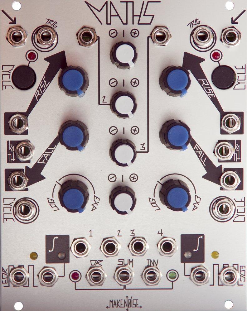
5 MATHS Channel Signal IN: Direct Coupled input to circuit. Use for Lag, Portamento, ASR (Attack Sustain Release type envelopes). Also input to SUM/ OR Bus. Range +/ 10V 2. Trigger IN: Gate or Pulse applied to this input will trigger the circuit regardless of activity at the Signal IN. The result being a 0V to 10V function, aka Envelope, whose characteristics are defined by the Rise, Fall, and Vari Response parameters. Use for Envelope, Pulse Delay, Clock Division, LFO Reset (only during Falling portion). 3. CYCLE LED: Indicates CYCLE ON or OFF. 4. CYCLE Button: Causes the circuit to self cycle, thus generating a repeating voltage function, aka LFO. Use for LFO, Clock, VCO. 5. RISE Panel Control: Sets the time it takes for the voltage function to ramp up. CW rotation increases Rise Time. 6. RISE CV IN: Linear control signal input for Rise parameter. Positive Control signals increase Rise Time, Negative control signals decrease Rise Time with respect to the Rise panel control setting. Range +/ 8V 7. FALL Panel Control: Sets the time it takes for the voltage function to ramp down. CW rotation increases Fall Time.
6 BOTH CV IN: Bi Polar Exponential control signal input for ENTIRE function. Contrary to the Rise and Fall CV IN, BOTH has an Exponential response and Positive control signals decrease total time while Negative control signals increase total time. Range +/ 8V 9. FALL CV IN: Linear control signal input for Fall parameter. Positive control signals increase Fall time, Negative control signals decrease Fall Time with respect to the Fall panel control. Range +/ 8V 10. Vari Response Panel Control: Sets the response curve of the voltage function. Response is continuously variable from Logarithmic through Linear to Exponential to Hyper Exponential. The Tick mark shows the Linear setting. 11. CYCLE IN: On Gate HIGH, circuit will CYCLE. On Gate LOW MATHS will not CYCLE (unless the CYCLE button is engaged). Requires minimum +2.5V for HIGH 12. End Of Rise OUT (EOR): Goes high at the end of the Rise portion of the function. 0V or 10V. 13. EOR LED: Indicates the states of the EOR output. Lights when EOR is HIGH. 14. Unity Signal OUT: signal from the Channel 1 circuit. 8V peak to peak when Cycling. Otherwise this output will follow the amplitude of the input. 15. Unity LED: indicates activity within the circuit. Positive voltages GREEN, Negative voltages RED.
7 MATHS Channel Signal IN: Direct Coupled input to circuit. Use for Lag, Portamento, ASR (Attack Sustain Release type envelopes). Also input to SUM/ OR Bus. Range +/ 10V 2. Trigger IN: Gate or Pulse applied to this input will trigger the circuit regardless of activity at the Signal IN. The result being a 0V to 10V function, aka Envelope, whose characteristics are defined by the Rise, Fall, and Vari Response parameters. Use for Envelope, Pulse Delay, Clock Division, LFO Reset (only during Falling portion). 3. CYCLE LED: Indicates CYCLE ON or OFF. 4. CYCLE Button: Causes the circuit to self cycle, thus generating a repeating voltage function, aka LFO. Use for LFO, Clock, VCO. 5. RISE Panel Control: Sets the time it takes for the voltage function to ramp up. CW rotation increases Rise Time. 6. RISE CV IN: Linear control signal input for Rise parameter. Positive Control signals increase Rise Time, Negative control signals decrease Rise Time with respect to the Rise panel control setting. Range +/ 8V 7. FALL Panel Control: Sets the time it takes for the voltage function to ramp down. CW rotation increases Fall Time.
8 BOTH CV IN: Bi Polar Exponential control signal input for ENTIRE function. Contrary to the Rise and Fall CV IN, BOTH has an Exponential response and Positive control signals decrease total time while Negative control signals increase total time. Range +/ 8V 9. FALL CV IN: Linear control signal input for Fall parameter. Positive control signals increase Fall time, Negative control signals decrease Fall Time with respect to the Fall panel control. Range +/ 8V 10. Vari Response Panel Control: Sets the response curve of the voltage function. Response is continuously variable from Logarithmic through Linear to Exponential to Hyper Exponential. The Tick mark shows the Linear setting. 11. CYCLE IN: On Gate HIGH, circuit will CYCLE. On Gate LOW MATHS will not CYCLE (unless the CYCLE button is engaged). Requires minimum +2.5V for HIGH 12. End Of Cycle OUT (EOC): Goes high at the end of the Fall portion of the function. 0V or 10V. 13. EOC LED: Indicates the states of the EOR output. Lights when EOC is HIGH. 14. Unity Signal OUT: signal from the Channel 1 circuit. 8V peak to peak when Cycling. Otherwise this output will follow the amplitude of the input. 15. Unity LED: indicates activity within the circuit. Positive voltages GREEN, Negative voltages RED.
9 SUM and OR Bus Signal IN Channel 2: Direct Coupled input to Attenuvertor and SUM/ OR Bus. Normalized to a +10V reference for generation of voltage offsets. Input Range +/ 10V 2. Signal IN Channel 3: Direct Coupled input to Attenuvertor and SUM/ OR Bus. Normalized to a +5V reference for generation of voltage offsets. Input Range +/ 10V 3. CH. 1 Attenuvertor Control: provides for scaling, attenuation and inversion of the signal being processed or generated by CH. 1. Connected to CH. 1 Variable OUT and SUM/ OR Bus. 4. CH. 2 Attenuvertor Control: provides for scaling, attenuation, amplification and inversion of signal patch to CH. 2 Signal IN. With no signal present it will control the level of the offset generated by CH. 2. Connected to CH. 2 Variable OUT and SUM/ OR Bus.. 5. CH. 3 Attenuvertor Control: provides for scaling, attenuation, amplification and inversion of signal patch to CH. 3 Signal IN. With no signal present it will control the level of the offset generated by CH. 3. Connected to CH. 3 Variable OUT and SUM/ OR Bus. 6. CH. 4 Attenuvertor Control: provides for scaling, attenuation and inversion of the signal being processed or generated by CH. 4. Connected to CH. 4 Variable OUT and SUM/ OR Bus.
10 CH. 1 Variable OUT: The applied signal as processed by CH. 1 controls. Normalized to the SUM and OR busses. Inserting a patch cable will remove the signal from the SUM and OR busses. Output Range +/ 10V 8. CH. 2 Variable OUT: The applied signal as processed by CH. 2 controls. Normalized to the SUM and OR busses. Inserting a patch cable will remove the signal from the SUM and OR busses. Output Range +/ 10V 9. CH. 3 Variable OUT: The applied signal as processed by CH. 3 controls. Normalized to the SUM and OR busses. Inserting a patch cable will remove the signal from the SUM and OR busses. Output Range +/ 10V 10. CH. 4 Variable OUT: The applied signal as processed by CH. 4 controls. Normalized to the SUM and OR busses. Inserting a patch cable will remove the signal from the SUM and OR busses. Output Range +/ 10V
11 OR Bus OUT: Result of the Analog Logic OR function with respect to the settings of the attenuvertor controls for channels 1, 2, 3 and 4. Range 0V to 10V. 12. SUM Bus OUT: Sum of the applied voltages with respect to the settings of the attenuvertor controls for channels 1, 2, 3 and 4. Range +/ 10V 13. INVerted SUM OUT: signal from SUM OUT turned upside down. Range +/ 10V 14. SUM Bus LEDs: indicate voltage activity in the SUM bus (and therefore the INVerted SUM and OR Bus as well). RED LED indicates negative voltages. GREEN LED indicates positive voltages.
12 MATHS is laid out top to bottom, with symmetrical features between CH. 1 and 4. The signal inputs are at the top, followed by the panel controls and control signal inputs at the middle. The signal outputs are at the bottom of the module. LEDs are placed near the signal they are indicating. Channels 1 and 4 are able to scale, invert or integrate an incoming signal. With no signal applied, these channels may be made to generate a variety of linear, logarithmic, or exponential functions upon the reception of a trigger, or continuously when the CYCLE is engaged. One small difference between CH. 1 and 4 is in their respective Pulse outputs; CH.1 having End of Rise and CH. 4 having End of Cycle. This was done to facilitate the creation of complex functions utilizing both CH. 1 and 4. Channels 2 and 3 are able to scale, amplify and invert an incoming signal. With no external signal applied, these channels generate DC offsets. The only difference between CH. 2 and 3 is that CH. 2 generates a +/ 10V offset while Ch. 3 generates a +/ 5V offset. All 4 channels have outputs (called Variable OUTs) which are normalized to a SUM, INVerted Sum and OR bus so that addition, subtraction, inversion and analog logic OR manipulations may be achieved. Inserting a plug to these Variable OUT sockets will remove the associated signal from the SUM and OR bus (Channels 1 and 4 have unity outputs, which are NOT normalized to the SUM and OR bus). These outputs are controlled by the 4 Attenuvertors at the center of the module. SIGNAL IN These inputs are all Direct Coupled to their associated circuit. This means they are able to pass both audio and control signals. These inputs are used to process external control voltages. CH. 1 and 4 Signal IN could also be used to generate Attack/ Sustain/ Release type envelopes from a gate signal. Channels 2 and 3 are also normalized to a voltage reference so that with nothing patched to the input, that channel could be used for generation of voltage offsets. This is useful for level shifting a function or other signal that is at one of the other channels by adding the voltage offset to that signal and taking the SUM OUT. Trigger IN CH. 1 and 4 also have a trigger input. A gate or pulse applied to this input will trigger the associated circuit regardless of activity at the Signal IN. The result being a 0V to 10V function, aka Envelope, whose characteristics are defined by the RISE, FALL, Vari Response and Attenuvertor parameters. This function will rise from 0V to 10V and then immediatly fall from 10V to 0V. There is NO SUSTAIN. To get a sustaining envelope function, use the Signal IN (see above). MATHS will re trigger during the falling portion of the function, but will NOT re trigger on the rising portion of the function. This allows clock and gate division since MATHS could be programmed to IGNORE incoming clocks and gates by setting the RISE Time to be greater then the time between the incoming clocks and/ or gates. CYCLE The CYCLE Button and CYCLE IN both do the same thing... they make MATHS self oscillate aka CYCLE, which are just fancy terms for LFO! When you want LFO, make MATHS CYCLE and you will be satisfied.


13 RISE/ FALL/ Vari Response These controls shape the signal that is output at the Unity Signal OUT and Variable OUT for CH. 1 and 4. The RISE and FALL controls determine how fast or slow the circuit will respond to signals applied to the Signal IN and Trigger IN. The range of times is larger then the typical Envelope or LFO. MATHS will create functions as slow as 25 minutes (Rise and Fall full CW and external control signals added to go into "slow ver drive") and as fast as 1khz (audio rate). RISE sets the amount of time the circuit takes to travel up to the maximum voltage. When triggered the circuit starts at 0V and travels up to 10V. RISE determines how long it takes for this to happen. When used to process external control voltages the signal applied to the Signal IN is either increasing, decreasing or at a steady state (doing nothing). RISE determines how fast that signal could increase. One thing MATHS cannot do is look into the future to know where an external control signal is headed, therefore MATHS cannot increase the rate at which an external voltage changes/ moves, it can only act upon the present and slow it down (or allow it to pass at same speed). FALL sets the amount of time the circuit takes to travel down to the minimum voltage. When triggered the voltage starts at 0V and travels up to 10V, at 10V the upper threshold is reached and the voltage begins to drop back down to 0V. FALL determines how long it takes for this to happen. When used to process external control voltages the signal applied to the Signal IN is either increasing, decreasing or at a steady state (doing nothing). FALL determines how fast that signal could decrease. Since it cannot look into the future to know where an external control signal is headed, MATHS cannot increase the rate at which an external voltage changes/ moves, it can only act upon the present and slow it down (or allow it to pass at same speed). Both RISE and FALL have independent CV inputs for voltage control over these parameters. If attenuation is required, use CH. 2 or CH. 3 in series to the desired destination. In addition to the RISE and FALL CV INs there is also the BOTH CV INs. The BOTH CV input changes the rate of the ENTIRE function. It also responds inversely to the RISE and FALL CV INs. More positive voltages make the entire function shorter and more negative voltages make the entire function longer. Vari Response shapes the above rates of change (RISE/ FALL) to be Logarithmic, Linear or Exponential (and everything in between these shapes). With the LOG response, the rate of change DECREASES and the voltage INCREASES. With EXPO response the rate of change INCREASES and the voltage INCREASES. The LINEAR response has no change in rate as the voltage changes. LOG EXPO LINEAR
14 Signal OUTS There is many different signal outputs on the MATHS. All of them are situated at the bottom of the module. Many of them have LEDs situated nearby for visual indication of the signals. The Variable OUTs These outputs are labelled 1, 2, 3 and 4 and are associated with the four Attenuvertor controls in the center of the module. These outputs are all determined by the settings of their associated controls, esp. the CH. 1 thru 4 Attenuvertor controls. All of these jacks are normalled to the SUM and OR Bus. With nothing patched to these outputs, the associated signal is injected into the SUM and OR Bus. When you patch a cable into any one of these output jacks, the associated signal willbe REMOVED from the SUM and OR Bus. These outputs are useful when you have a modulation destination where there is no attenuation or inversion available (the CV inputs on the MATHS or FUNCTION modules for example). They are also useful when you want to create a variation of signal that is at a different amplitude or phase. EOR OUT This is the End Of Rise output for CH. 1. This is an event signal. It is either at 0V or 10V and nothing between. It defaults to 0V, or LOW when there is no activity. The event in this case is when the associated channel reaches the highest voltage to which it will travel. This is a good signal to choose for Clocking or Pulse shaped LFO. It is also useful for Pulse Delay and clock division since the Rise will set the amount of timeit takes for this output to go HIGH. EOC OUT This is the End Of Cycle output for CH. 4 This is an event signal. It is either at 0V or 10V and nothing between. It defaults to +10V, or HIGH, when there is no activity. The event in this case is when the associated channel reaches the lowest voltage to which it will travel. The associated LED will be lighted when nothing is happening. This is a good signal to choose for Clocking or Pulse shaped LFO. Unity Signal OUTs CH. 1 and 4 These outputs are tapped directly off the core of the associated channel. They are not affected by the channel's Attenuvertor. Patching into this output will NOT remove the signal from the SUM and OR Buses. This is a good output to use when you do not require attenuation or inversion or when you want to use the signal both independently and within the SUM/ OR Bus. OR OUT This is the output from the analog OR circuit. The inputs are CH. 1, 2, 3 and 4 Variable OUTputs. It will always output the highest voltage out of all the voltages applied to the inputs. Some people call this a Maximum Voltage selector circuit! The attenuators allow for weighting the signals. It will not respond to negative voltages, therefore it could also be used to rectify a signal. Useful for creating variations on a modulation or sending CV to inputs that only respond to positive voltages (Organize CV IN on the Phonogene). SUM OUT This is the output from the analog SUM circuit. The inputs are CH. 1, 2, 3 and 4 Variable OUTs. Depending upon how the Attenuvertors are set, you could add, invert or subtract voltages from each other using this circuit. This is a good output to use for combining several control signals in order to generate more complex modulations. INV OUT This is the inverted version of the SUM output. It will allow you to modulate backwards!
15 Tips & Tricks Longer cycles will be achieved with more Logarithmic response curves. The fastest, sharpest functions will be achieved with extreme exponential response curves. Adjustment to the response curve will affect RISE and FALL Times. To achieve longer or shorter RISE and FALL Times than available from Panel Controls, apply a voltage offset to the Control Signal Inputs. Use CH. 2 or 3 for this offset voltage. Use the INV SUM OUT where you require reversed modulation but do not have means for inversion at the CV destination (MIX CV IN on ECHOPHON for example). Feeding an inverted signal from MATHS back into the MATHS at any of the CV inputs is highly useful for creating responses that are not covered by the Vari Response control alone. When utilizing the SUM and OR outputs, set any unused CH. 2 or 3 to NOON or insert a dummy patch cable to Signal Input of associated channel to avoid unwanted offsets. If it is desired that a signal processed or generated by CH. 1, 4 is both on the SUM, INV and OR busses AND available as an independent output, utilize the Unity Signal OUT, as it is NOT normalized to the SUM and OR Busses. OR output will not respond to or generate negative voltages. End of Rise and End of Cycle are useful for generating complex control voltage functions where CH. 1 and CH. 4 will trigger from each other. Patch to each others Trigger, Signal and CYCLE inputs.
16 Patch Ideas: Analog Voltages, Low Frequency Oscillators Typical Voltage Controlled Triangle Function (Triangle LFO) Set CH. 1 (or 4) to self Cycle. Set RISE and FALL Panel Control to NOON. Set CH. 2 Attenuvertor to NOON. Patch SUM OUT to Both Control Input. Apply desired frequency modulation to CH. 3 Signal Input. The CH. 2 Attenuvertor will set Frequency. Output is taken from Signal OUTs of associated channel. Setting RISE and FALL parameters further CW will provide longer cycles. Setting these parameters further CCW will provide short cycles, up to audio rate. The resulting function may be further processed with attenuation and/ or inversion by the Attenuvertor. Alternatively, take output from the cycling channel's UNITY output and patch the Variable OUT to the RISE or FALL CV IN to morph LFO shapes with with the CH 1 (or 4) Attenuvertor. Typical Voltage Controlled Ramp Function (Saw/ Ramp LFO) Same as above, only the RISE parameter is set FULL CCW, FALL parameter is set to at least NOON. Arcade Trill (Complex LFO) Set CH. 4 RISE and FALL to NOON, Attenuvertor to 9 o'clock. Patch EOC to CH. 1 Trigger IN. Patch CH. 4 Signal OUT to CH. 1 Both IN. Set CH. 1 RISE to NOON, FALL to full CCW. Engage CH. 4 CYCLE switch. Apply Signal OUT CH. 1 to modulation destination. CH. 4 Attenuvertor, RISE and Vari Rsponse Parameters vary trill. Chaotic Trill (requires MMG or other Direct Coupled LP filter) Begin with Arcade Trill patch. set CH. 1 Attenuvertor to 1 o'clock. Apply CH. 1 Signal OUT to MMG DC Signal IN. Patch EOR to to MMG AC Signal IN, set to LP mode, no feedback, starting with FREQ at full CCW. Apply MMG Signal OUT to MATHS CH. 4 Both IN. Patch CH. 4 Variable OUT to CH. 1 BOTH CV IN. Unity Signal OUT to modulation destination. MMG FREQ and Signal IN controls and MATHS CH. 1 and 4 Attenuvertors will be of great interest in addition to the RISE and FALL parameters. 281 Quadrature Mode (Complex LFO) In this patch, CH. 1,4 work in tandem to provide functions shifted by ninety degrees. With both Cycle Switches UN ENGAGED, Patch End of RISE (CH. 1) to Trigger IN CH. 4. Patch End of Cycle (CH. 4) to Trigger IN CH. 1. If both CH.1 and 4 do not begin cycling, engage CH. 1 CYCLE Briefly. With both channels cycling, apply their respective Signal outputs to two different modulation destinations, for example two channels of the Optomix.
17 Patch Ideas: Analog Voltages, Triggered Functions/ Envelopes Voltage Controlled Transient Function Generator (Attack/ Decay EG) A pulse or gate applied to the Trigger IN of CH. 1 or 4 will start the transient function which rises from 0V to 10V at a rate determined by the RISE parameter and then falls from 10V to 0V at a rate determined by the FALL parameter. This function is re trigger able during the falling portion. RISE and FALL are independently voltage controllable, with variable response from Log thru Linear to Exponential, as set by the Vari Response panel Control. The resulting function may be further processed with attenuation and/ or inversion by the Attenuvertor. Voltage Controlled Sustained Function Generator (A/S/R EG) A gate applied to the Signal IN of CH. 1 or 4 will start the function which rises from 0V to the level of the applied Gate, at a rate determined by the RISE parameter, Sustains at that level until the Gate signal ends, and then falls from that level to 0V at a rate determined by the FALL parameter. RISE and FALL are independently voltage controllable, with variable response as set by the Vari Response panel Control. The resulting function may be further processed with attenuation and/ or inversion by the Attenuvertor. Typical Voltage Controlled ADSR type Envelope Apply Gate signal to CH.1 Signal In. Set CH. 1 Attenuvertor to less then Full CW. Patch CH. 1 End of Rise to CH. 4 Trigger IN. Set CH. 4 Attenuvertor to Full CW. Take output from OR bus OUT, being sure that CH. 2,3 are set to NOON if not in use. In this patch CH. 1 and 4 RISE will control the Attack Time. For typical ADSR adjust these parameters to be similar (Setting CH. 1 RISE to be longer then CH. 4 will or vice versa, will produce two attack stages). CH. 4 FALL parameter will adjust the Decay stage of the envelope. CH. 1 Attenuvertor will set the Sustain level, which MUST be lower then that same parameter on CH. 4. Finally CH. 1 FALL will set the Release Time. Bouncing Ball, 2013 edition thanx to Pete Speer Set CH. 1 RISE full CCW, FALL to 3:00, response to Linear. Set CH. 4 RISE full CCW, FALL to 11:00, response to Linear. Patch CH. 1 EOR to CH. 4 CYCLE In. Patch CH. 4 Output to VCA or LPG control input. Patch a gate or trigger source, such as the touch gate from Pressure Points, to CH. 1 TRIG in. Adjust Channel 4 RISE and FALL for variations. Independent Contours thanx to Navs By changing the level and polarity of the Variable OUT of CH. 1, 4 with the Attenuvertor, and feeding that signal back into CH.1, 4 at RISE or FALL Control IN, independent control of the corresponding slope is achieved. Take output from Unity Signal OUT. Best to have the Response panel control set to NOON. Independent Complex Contours Same as above, but additional control is possible by using the EOC or EOR to trigger the opposite channel, and use the SUM or OR output to RISE, FALL or BOTH of the original channel. Alter RISE, FALL, attenuversion and response curve of opposite channel to acheive various shapes. Asymmetrical Trilling Envelope thanx to Walker Farrell Engage cycling on CH. 1, or apply a signal of your choice to its Trigger or Signal IN. Set RISE and FALL to 12:00 with Linear response. Patch CH. 1 EOR to CH. 4 CYCLE input. Set CH. 4 RISE to 1:00 and FALL to 11:00, with Exponential response. Take output from OR (with CH. 2 and 3 set to 12:00). The resulting envelope has a "trill" during the fall portion. Adjust relative levels and RISE/FALL times and responses. Alternatively, swap channels and use the EOC output to CH. 1's CYCLE input for trilling during the rise portio
18 Patch Ideas: Analog Signal Processing, Voltage MATHS! ADD, Subtract Control Signals Apply signals to be added/ subtracted to any combination of Signal IN CH. 1,2,3,4 (when using CH. 1,4 RISE and FALL must be set to full CCW, and Cycle switch not engaged). For channels to be added, set Attenuvertor controls to full CW. Set Attenuvertors for channels to be subtracted to full CCW. Take output from SUM OUT. VC Portamento/ LAG/ Slew Processor A signal applied to the Signal IN, is slewed according to the RISE and FALL parameters. Variable response from Log thru Linear to Exponential, is as set by the Vari Response panel Control. The resulting function may be further processed with attenuation and/ or inversion by the Attenuator Panel Control. Envelope Follower Apply Signal to be followed to Signal IN CH. 1 or 4. Set RISE to NOON. Set and or modulate FALL Time to achieve different responses. Take output from associated channel Signal OUT for positive and negative Peak Detection. Take output from OR buss OUT to achieve more typical Positive Envelope Follower function. Peak Detector Patch signal to be detected to CH. 1 Signal IN. Set RISE and FALL to 3 'o' Clock. Take output from Signal OUT. Gate out from EOR OUT. Voltage Mirror Apply Control Signal to be mirrored to CH. 2 Signal IN. Set CH. 2 Attenuvertor to Full CCW. With nothing inserted at CH. 3 Signal IN (so as to generate an offset), set CH. 3 Attenuvertor to full CW. Take output from SUM OUT. Voltage Comparator/ Gate Extraction w/ variable width Apply signal to be compared to CH. 3 Signal IN. Set Attenuvertor to greater than 50%. Use CH. 2 for comparing voltage (with or without something patched). Patch SUM OUT to CH. 1 Signal IN. Set CH. 1 RISE and FALL to full CCW. Take extracted Gate from EOR. CH. 3 Attenuvertor acts as the input level setting, applicable values being between NOON and Full CW. CH. 2 acts as the threshold setting applicable values being from Full CCW to NOON. Values closer to NOON will be LOWER thresholds. Setting the RISE more CW, you will be able to Delay the derived gate. Setting FALL more CW you will vary the width of the derived Gate. Use CH. 4 for Envelope Follower patch, and CH. 3, 2 & 1 for Gate extraction, and you have a very powerful system for external signal processing. Half Wave Rectification Apply bi polar signal to CH. 1, 2, 3, 4 IN. Take output from OR out. Mind the normalizations to the OR buss. Full Wave Rectification Mult signal to be rectified to both CH. 2 and 3 IN. CH 2 Scaling/ Inversion set to Full CW, CH. 3 Scaling/ Inversion set to Full CCW. Take output from OR Out. Vary the Scaling. Multiplication Apply positive going control signal to be multiplied to CH1 or 4 Signal IN. Set RISE to full CW, FALL to Full CCW. Apply positive going, multiplier Control Signal to BOTH Control IN. Take output from corresponding Signal OUT.
19 Pseudo VCA with clipping Thanx to Walker Farrell Patch audio signal to CH. 1, with RISE and FALL at full CCW, or cycle CH. 1 at audio rate. Take output from SUM out. Set initial level with CH. 1 panel control. Set CH. 2 panel control full CW to generate a 10v offset. Audio will start to clip and may become silent. If it's still audible, apply an additional positive offset with CH. 3 panel control until it is just silent. Set CH. 4 panel control to full CCW and apply envelope to Signal IN, or generate envelope with CH. 4. This patch creates a VCA with assymetrical clipping in the waveform. It will work with CV also, but be sure to adjust CV input settings to deal with the large base offset. The INV output may be more useful in some situations. Patch Ideas: Digital Signals, Clocks, Gates, Pulses, Events, Timing Typical Voltage Controlled Pulse/ Clock w/ Voltage Controlled Run/ Stop (Clock, pulse LFO) Same as above, only the output is taken from EOC or EOR. CH. 1, RISE parameter will more effectively adjust frequency, and CH. 1 FALL parameter will adjust pulse width. With CH. 4, the opposite is true where RISE adjust more effectively Width and FALL adjust frequency. In both channels all adjustment to RISE and FALL parameters will affect frequency. Use CYCLE IN for Run/ Stop control. Voltage Controlled Pulse Delay Processor Apply Trigger or Gate to Trigger IN if CH. 1. Take output from End Of Rise. RISE parameter will set delay and FALL parameter will adjust width of the resulting pulse. Voltage Controlled Clock Divider Clock signal applied to Trigger IN CH. 1 or 4 is processed by a divisor as set by RISE parameter. Increasing RISE sets divisor higher, resulting in larger divisions. Fall time will adjust the width of the resulting clock. If the Width is adjust to be greater the the total time of the division the output will remain high. FLIP FLOP (1 Bit Memory) In this patch CH. 1 Trigger IN acts as the Set input, and CH. 1 BOTH Contrl IN acts as the Reset input. Apply Reset signal to CH. 1 BOTH Control IN. Apply Gate or logic signal to CH. 1 Trigger IN. Set RISE to Full CCW, FALL to Full CW, Vari Response to Linear. Take Q output from EOC. Patch EOC to CH. 4 Signal to achieve NOT Q at the EOC OUT. This patch has a memory limit of about 3 minutes, after which it forgets the one thing you told it to remember. Logic Invertor Apply logic gate to CH. 4 Signal IN. Take output from CH. 4 EOC. Comparator/Gate Extractor (a new take) Send signal to be comparated to CH. 2 IN. Set CH. 3 panel control into the negative range. Patch SUM out into CH. 1 Signal IN. Set CH. 1 RISE and FALL to 0. Take outpur from CH. 1 EOR. Observe signal polarity with CH. 1 UNITY LED. When signal goes slightly positive, EOR will trip. Use CH. 3 panel control to set the threshold. Some attenuation of CH. 2 may be necessary to find the right range for a given signal. Use CH. 1 FALL control to make the gates longer. CH. 1 RISE control sets the length of time the signal must be above the threshold to trip the comparator.
MATHS Limited Warranty Installation
 v2.6 2 MATHS Limited Warranty ----------------------------------------------------3 Installation ----------------------------------------------------------4 Overview ---------------------------------------------------------5
Make Noise Maths V2 Illustrated supplement. by Demonam
 Make Noise Maths V2 Illustrated supplement by Demonam Index 01... Typical Voltage Controlled Triangle Function (Triangle LFO) 02... Typical Voltage Controlled Ramp Function (Saw/ Ramp LFO) 03... Arcade
Table of Contents: Limited Warranty:
 v 1.0 2 Table of Contents: ----------------------------------------------------2 Limited Warranty: ----------------------------------------------------3 Installation: -------------------------------------------------------------4
TELEPLEXER Limited Warranty Installation
 v. TELEPLEXER Limited Warranty ---------------------------------------------------- Installation --------------------------------------------------4 Overview ---------------------------------------------------5
moddemix: Limited Warranty: Installation:
 moddemix v2.3 1 moddemix: Limited Warranty: ----------------------------------------------------2 Installation: ----------------------------------------------------3 Panel Controls: --------------------------------------------4
MMG: Limited Warranty: Installation:
 v2.4 2 MMG: Limited Warranty: ----------------------------------------------------3 Installation: ----------------------------------------------------4 Overview:---------------------------------------------------------------5
STO Limited Warranty Installation Overview
 v2.5 2 STO Limited Warranty ----------------------------------------------------3 Installation --------------------------------------------------4 Overview --------------------------------------------------------5
Table of Contents: Limited Warranty:
 v 1.0 2 Table of Contents: ----------------------------------------------------2 Limited Warranty: ----------------------------------------------------3 Installation: ------------------------------------------------------------4
Make Noise implies and accepts no responsibility for harm to person or apparatus caused through operation of this product.
 Pressure Points Limited WARRANTY: Make Noise warrants this product to be free of defects in materials or construction for a period of one year from the date of manufacture. Malfunction resulting from wrong
Make Noise implies and accepts no responsibility for harm to person or apparatus caused through operation of this product.
 Optomix Limited WARRANTY: Make Noise warrants this product to be free of defects in materials or construction for a period of one year from the date of manufacture. Malfunction resulting from wrong power
Optomix Limited Warranty: Installation:
 v2.4 1 Optomix Limited Warranty: ----------------------------------------------------2 Installation: ----------------------------------------------------------3 Panel Controls:-----------------------------------------------------4
Limited WARRANTY: Make Noise implies and accepts no responsibility for harm to person or apparatus caused through operation of this product.
 v 1.0 Limited WARRANTY: Make Noise warrants this product to be free of defects in materials or construction for a period of one year from the date of purchase (proof of purchase/invoice required). Malfunction
FXDf Limited Warranty: Installation: Expansion:
 v2.3 1 FXDf Limited Warranty:----------------------------------------2 Installation: --------------------------------------------------3 Expansion: ------------------------------------------------------4
Introduction OUT -12V. The Rampage is Befaco s approach to an old invention: the Serge/Buchla ramp generator.
 RAMPAGE USER MANUAL Thanks for your Befaco purchase! Before you plug this module in... 1. Disconnect your cabinet from mains. 2. Triple check the power cord polarity. The colored line on the cable (pin
Please contact with any questions, needs & comments... otherwise go MAKE NOISE.
 DPO Limited WARRANTY: Make Noise warrants this product to be free of defects in materials or construction for a period of one year from the date of manufacture. Malfunction resulting from wrong power supply
Make Noise Wogglebug
 Make Noise Wogglebug IS THE WOGGLEBUG MY SYNTHESIZER'S ID MONSTER? SHOULD I BEWARE the WOGGLEBUG? YES, and Maybe. The "WoggleBug" is a random voltage generator, originally designed by Grant Richter of
Limited WARRANTY: Make Noise implies and accepts no responsibility for harm to person or apparatus caused through operation of this product.
 v2.6 2 DPO Limited Warranty ----------------------------------------------------3 Installation --------------------------------------------------4 Overview ----------------------------------------------------------5
RxMx Limited Warranty Installation
 v2.4 2 RxMx Limited Warranty -----------------------------------------------------3 Installation ----------------------------------------------------------------4 Expansion -----------------------------------------------------------------------5
DOEPFER System A-100 Synthesizer Voice A Introduction. Fig. 1: A sketch
 DOEPFER System A-100 Synthesizer Voice A-111-5 1. Introduction Fig. 1: A-111-5 sketch 1 Synthesizer Voice A-111-5 System A-100 DOEPFER Module A-111-5 is a complete monophonic synthesizer module that includes
MYSTERON FCC Limited Warranty
 v2.4 2 MYSTERON FCC ----------------------------------------------------------------------3 Limited Warranty ----------------------------------------------------4 Installation ----------------------------------------------------------5
Galilean Moons. dual amplitude transmutator. USER MANUAL v1.02
 Galilean Moons dual amplitude transmutator USER MANUAL v1.02 Contents Contents... 2 Introduction... 3 Module Features and Specifications... 4 Module Description... 4 Features List... 4 Technical Details...
VCA. Voltage Controlled Amplifier.
 VCA Voltage Controlled Amplifier www.tiptopaudio.com Tiptop Audio VCA User Manual The Tiptop Audio VCA is a single-channel variable-slope voltage-controlled amplifier in Eurorack format. It has the following
Shifting Inverting Signal Mingler (SISM) from 4ms Company Eurorack Module User Manual
 from 4ms Company Eurorack Module User Manual") Shifting Inverting Signal Mingler (SISM) from 4ms Company Eurorack Module User Manual The Shifting Inverting Signal Mingler (SISM) is a 4-channel voltage manipulator that can scale, invert, attenuate,
Shifting Inverting Signal Mingler (SISM) from 4ms Company Eurorack Module User Manual The Shifting Inverting Signal Mingler (SISM) is a 4-channel voltage manipulator that can scale, invert, attenuate,
Q179 Envelope++ Q179 Envelope++ Specifications. Mar 20, 2017
 Mar 20, 2017 The Q179 Envelope++ module is a full-featured voltage-controlled envelope generator with many unique features including bizarre curves, a VCA and looping. Special modes offer dual-envelopes
Black & Gold Shared System
 Black & Gold Shared System ( v1.11 ) Table of Contents: Getting Started: FCC ----------------------------------------------------------------------3 Limited Warranty ----------------------------------------------------4
HexVCA Manual v1.0. Front Panel. 1 - VCA Offset CV offset, also referred to as bias knob. CV indicator LED. 2 - IN 1-6 The signal input of the VCAs.
 HexVCA Manual v1.0 The HexVCA contains six separate DC coupled logarithmic VCAs that have their outputs normalled to two outputs. The front panel outputs of each VCA is a switching jack which breaks the
BINARY. User Manual. Version 1.0
 !! BINARY User Manual Version 1.0 BINARY Binary is a 1-bit analog computer that takes up to six inputs and determines whether the output voltage should be high (+) or low (). Binary was designed to take
PITTSBURGH MODULAR SYSTEM 10.1 and SYNTHESIZER MANUAL AND PATCH GUIDE
 PITTSBURGH MODULAR SYSTEM 10.1 and 10.1+ SYNTHESIZER MANUAL AND PATCH GUIDE 1 Important Instructions PLEASE READ Read Instructions: Please read the System 10.1 Synthesizer manual completely before use
OCS-2 User Documentation
 OCS-2 User Documentation nozoid.com 1/17 Feature This is the audio path wired inside the synthesizer. The VCOs are oscillators that generates tune The MIX allow to combine this 2 sound sources into 1 The
SYSTEM-100 PLUG-OUT Software Synthesizer Owner s Manual
 SYSTEM-100 PLUG-OUT Software Synthesizer Owner s Manual Copyright 2015 ROLAND CORPORATION All rights reserved. No part of this publication may be reproduced in any form without the written permission of
SPUTNIK MODULAR QUAD FUNCTION & TRIGGER SOURCE MANUAL V
 MANUAL V.1 / OUT A1 CV PULSE 1 PULSE 1 D1 CV OUT 1 OUT 1+2 OUT 2 +90 A2 CV PULSE 2 D2 CV PULSE 2 OUT 2 0 MAX A3 CV PULSE 3 D3 CV PULSE 3 OUT 3 OUT 3+4 OUT 4 +90 A4 CV PULSE 4 D4 CV PULSE 4 OUT 4 0 MAX
PITTSBURGH MODULAR FOUNDATION 3.1 and 3.1+ SYNTHESIZER MANUAL AND PATCH GUIDE
 PITTSBURGH MODULAR FOUNDATION 3.1 and 3.1+ SYNTHESIZER MANUAL AND PATCH GUIDE 1 Important Instructions PLEASE READ Read Instructions: Please read the Foundation 3.1 Synthesizer manual completely before
Mixwitch Mixer & Switcher
 Mixwitch Mixer & Switcher Voltage & clock-controlled analog switch with mixer Introduction Focused versatility seems an oxymoron when describing the features that led us to design the Mixwitch. With only
USER MANUAL. MALEKKO HEAVY INDUSTRY CORPORATION malekkoheavyindustry.com Rev A
 USER MANUAL MALEKKO HEAVY INDUSTRY CORPORATION malekkoheavyindustry.com Rev A Sneak Attack is a digitally controlled analog VCA pedal that can also be manually triggered or used in a tremolo mode. The
pittsburgh modular synthesizers lifeforms sv-1 user manual v.1
 pittsburgh modular synthesizers lifeforms sv-1 user manual v.1 the heart and soul of modular synthesis The Pittsburgh Modular Synthesizers Lifeforms SV-1 is a complete dual oscillator synthesizer, designed
4ms Pingable Envelope Generator
 4ms Pingable Envelope Generator Eurorack Module User Manual v2012-12-20 The Pingable Envelope Generator (PEG) from 4ms Company is a dual envelope generator whose envelope lengths are set by the time between
NOZORI 84 modules documentation
 NOZORI 84 modules documentation A single piece of paper can be folded into innumerable shapes. In the same way, a single Nozori hardware can morph into multiple modules. Changing functionality is as simple
ALM-011. Akemie s Castle. - Operation Manual -
 ALM-011 Akemie s Castle - Operation Manual - (V0.2) Introduction... 3 Technical Specifications 3 Background & Caveats... 4 Core Operation... 5 Panel Layout 5 General Usage 7 Patch Ideas... 13 Tuning Calibration...
A-167 Comparator. 1. Introduction. doepfer System A CMP A-167
 doepfer System A - 100 CMP A-167 1. Introduction - In - In A-167 Module A-167 compares analog voltages and derives a gate signal. The state of the gate output (low/ high) depends upon which of the voltages
Q181RC Ribbon Controller
 The Controller produces a varying voltage as you move your finger along the ribbon strip. Great for pitch bending, playing notes, controlling filter frequency, or other parameters in the synthesizer system.
MMO-4 User Documentation
 MMO-4 User Documentation nozoid.com This is a preliminary documentation 1/9 Feature This is the audio path wired inside the synthesizer. Modulation CV are routed to modulation fader in a digital matrix.
A-130 VCA-LIN. doepfer System A VCA A-130 / A Introduction
 doepfer System A - 100 VCA A-130 / A-131 1. Introduction 1 Audio Audio A-130 VCA-LIN. Audio Modules A-130 (Linear VCA) and A-131 (Exp. VCA) provide voltage-controlled amplification. H This section of the
BATUMI. quadruple low frequency oscillator. Model of operator s manual rev. 1974/4.0
 BATUMI quadruple low frequency oscillator operator s manual rev. 1974/4.0 Model of 1974 module explained SALUT Thank you for purchasing this Xaoc Devices product. Batumi is a fully voltage-controlled quadruple
PULSAR DUAL LFO OPERATION MANUAL
 PULSAR DUAL LFO OPERATION MANUAL The information in this document is subject to change without notice and does not represent a commitment on the part of Propellerhead Software AB. The software described
Q181EB Expression Block Controller
 The controller produces a voltage as you press the block, similar to the Ondes Martenot and other instruments. Perfect for controlling amplitude as you play notes on the keyboard, to control filter frequency,
makenoisemusic.com Make Noise Co., 414 Haywood Road, Asheville, NC 28806
 Erbe-Verb v2.4 2 ERBE-VERB FCC -----------------------------------------------------3 Limited Warranty ----------------------------------------4 Installation --------------------------------------------------5
MODEL 9791 HERTZ DONUT OPERATOR S MANUAL. Dual DIgital Oscillator with Internal Modulation Bus
 MODEL 9791 HERTZ DONUT OPERATOR S MANUAL Dual DIgital Oscillator with Internal Modulation Bus THE HARVESTMAN-9791 HERTZ DONUT USER S MANUAL Front Panel Key Introduction Table of Contents Configuration
Use the patch browser to load factory patches or save or load your own custom patches.
 1.0.1 User Manual 2 Overview Movement is an eight-stage arbitrary waveform generator that can act as an envelope, LFO, or high-frequency oscillator depending on how it is configured. The interactive graphical
Analog Synthesizer: Functional Description
 Analog Synthesizer: Functional Description Documentation and Technical Information Nolan Lem (2013) Abstract This analog audio synthesizer consists of a keyboard controller paired with several modules
User Guide V
 XV User Guide V1.10 25-02-2017 Diode Ladder Wave Filter Thank you for purchasing the AJH Synth Sonic XV Eurorack synthesiser module, which like all AJH Synth products, has been designed and handbuilt in
pittsburgh modular synthesizers microvolt 3900 manual
 pittsburgh modular synthesizers microvolt 3900 manual 2 Thank You! Thank you for purchasing the Microvolt 3900. Your investment in our ideas help support innovative, boutique synthesizer design. Looking
MMO-3 User Documentation
 MMO-3 User Documentation nozoid.com/mmo-3 1/15 MMO-3 is a digital, semi-modular, monophonic but stereo synthesizer. Built around various types of modulation synthesis, this synthesizer is mostly dedicated
operator s manual rev. 1948/2.0 SEWASTOPOL audio port & voltage extractor ii Model of 1948
 operator s manual rev. 198/.0 SEWASTOPOL audio port & voltage extractor ii Model of 198 module explained SALUT Thank you for purchasing this Xaoc Devices product. Sewastopol is a multifunction eurorack
1. Introduction Module A-138c is a four channel mixer, that allows to
 doepfer System A - 100 Polarizing Mixer A-138c 1. Introduction Module A-138c is a four channel mixer, that allows to add or subtract four incoming voltages to the output signal. In the middle position
DOEPFER System A-100 Quad ADSR A Introduction
 DOEPFER System A-100 Quad ADSR A-143-2 Fig. 1: A-143-2 Controls, Inputs and Outputs 1. Introduction Module A-143-2 contains four independent ADSR-type envelope generators. Each sub-unit has available the
P9700S Overview. In a P9700S, the 9700K MIDI2CV8 is the power source for the other modules in the kit. A separate power supply is not needed.
 P9700S Overview In a P9700S, the 9700K MIDI2CV8 is the power source for the other modules in the kit. A separate power supply is not needed. The wall-mount transformer for the 9700K is an ac power source
Understanding and Using Your. moogerfooger. CP-251 Control Processor. Moog Music Inc. Asheville, NC USA 2000, 2003 by Moog Music Inc.
 Understanding and Using Your moogerfooger CP-251 Control Processor Moog Music Inc. Asheville, NC USA 2000, 2003 by Moog Music Inc. Welcome to the world of moogerfooger Analog Effects Modules! Your Model
DOEPFER System A-100 X-treme Filter A Introduction
 DOEPFER System A-100 X-treme Filter A-106-1 Fig. 1: A-106-1 Controls and In/Outputs 1. Introduction Module A-106-1 is an unique low/high pass filter and has it's origin in our experiments to built a MS20
Music Easel Aux Card User s Guide v1.0 by Joel Davel 1/15/2017
 Music Easel Aux Card User s Guide v1.0 by Joel Davel 1/15/2017 Congratulations!!!! The Aux Card is a natural complement to the Easel and way to expand your palette. Introducing the Music Easel Auxilary
Analog/Digital Guitar Synthesizer. Erin Browning Matthew Mohn Michael Senejoa
 Analog/Digital Guitar Synthesizer Erin Browning Matthew Mohn Michael Senejoa Project Definition To use a guitar as a functional controller for an analog/digital synthesizer by taking information from a
Make Noise implies and accepts no responsibility for harm to person or apparatus caused through operation of this product.
 René Limited WARRANTY: Make Noise warrants this product to be free of defects in materials or construction for a period of one year from the date of manufacture. Malfunction resulting from wrong power
Quick Start. Overview Blamsoft, Inc. All rights reserved.
 1.0.1 User Manual 2 Quick Start Viking Synth is an Audio Unit Extension Instrument that works as a plug-in inside host apps. To start using Viking Synth, open up your favorite host that supports Audio
A-116 VCW. 1. Introduction. doepfer System A VC Waveform Processor A-116
 doepfer System A - 100 VC Waveform Processor A-116 1. Introduction Lev. CCV SCV Audio In CV Symm. CV Audio Out A-116 VCW Module A-116 (Voltage Controlled Waveform Processor) provides voltage-controlled
Noise Engineering. Sinclastic Empulatrix Simple Attack-Release Envelope with Voltage Controlled Clamp. Overview
 Simple - with Voltage Controlled Clamp Overview Type /VCA Size 4HP Eurorack Depth.8 inches Power 2x5 Eurorack +12 ma 15-12 ma 25 is a 4HP envelope generator with a voltage controlled clamp. e envelope
Euro Rack Series. Classic VCA. User Manual. Oakley Sound Systems. Discrete Core Voltage Controlled Amplifier V2.3
 Oakley Sound Systems Euro Rack Series Classic VCA Discrete Core Voltage Controlled Amplifier User Manual V2.3 Tony Allgood Oakley Sound Systems CARLISLE United Kingdom Introduction This is the User Manual
SCHLAPPI ENGINEERING A N G L E G R I N D E R MANUAL
 SCHLAPPI ENGEERG GL AN E GRDE M A N UA L R SPECIFICATIONS SCHLAPPI ENGEERG Quadrature Sine Wave VCO / State Variable Filter -with four phase related outputs: 0, 90, 180, 270 -or filter response outputs:
1. Introduction. doepfer System A VC Signal Processor A-109
 doepfer System A - 100 VC Signal Processor A-109 1. Introduction Module A-109 is a voltage controlled audio signal processor containing the components VCF, VCA and PAN (see fig. 1 on page 4). The module
REV 7. v.1.16
 5.19.16 REV 7 v.1.16 1 FCC: ----------------------------------------------------------------------2 Limited Warranty: ----------------------------------------------------3 Overview:------------------------------------------------------------4
Q181V Whammy Bar Controller
 This document covers our Whammy Bar controllers in these configurations: Q181V1 Single-axis Whammy Bar in a single-channel Q181 panel Q181V1 Whammy Bar Q182V2 Dual-axis Whammy Bar in a dual-channel Q182
Manual installation guide v1.2
 Manual installation guide v1.2 Hands up, or we will cross thru zero! I m your Furthrrrr Instant thru-zero linear fm in your Furthrrrr Generator 16-pin DIP IC chip VCO Core replacement that works with any
twincussion User Guide
 twincussion User Guide Foreword Analog drum synthesizers are simply unbeatable! No matter how many thousand drum sounds your sample library offers, it will never replace the charm and character of real
QCD Expander from 4ms Company Eurorack Module User Manual
 QCD Expander from 4ms Company Eurorack Module User Manual The QCD Expander from 4ms Company is an expansion module for the Quad Clock Distributor (QCD). The QCD Expander requires the QCD to function, and
RENE FCC: Limited Warranty:
 v2.3 RENE FCC:---------------------------------------------------------------------2 Limited Warranty: -----------------------------------------------------3 Installation: ----------------------------------------------------------------4
BoomTschak User s Guide
 BoomTschak User s Guide Audio Damage, Inc. 1 November 2016 The information in this document is subject to change without notice and does not represent a commitment on the part of Audio Damage, Inc. No
AtomoSynth MochikaX2 v1.0
 AtomoSynth MochikaX2 v1.0 Thank you for purchasing the AtomoSynth, Mochika X2 version 1.0. Analog synthesizer sequencer. In order to enjoy long and trouble free use, please read this manual carefully and
Department of Electronics & Telecommunication Engg. LAB MANUAL. B.Tech V Semester [ ] (Branch: ETE)
![Department of Electronics & Telecommunication Engg. LAB MANUAL. B.Tech V Semester [ ] (Branch: ETE)](/thumbs/86/93078052.jpg "Department of Electronics & Telecommunication Engg. LAB MANUAL. B.Tech V Semester [ ] (Branch: ETE)") Department of Electronics & Telecommunication Engg. LAB MANUAL SUBJECT:-DIGITAL COMMUNICATION SYSTEM [BTEC-501] B.Tech V Semester [2013-14] (Branch: ETE) KCT COLLEGE OF ENGG & TECH., FATEHGARH PUNJAB TECHNICAL
Department of Electronics & Telecommunication Engg. LAB MANUAL SUBJECT:-DIGITAL COMMUNICATION SYSTEM [BTEC-501] B.Tech V Semester [2013-14] (Branch: ETE) KCT COLLEGE OF ENGG & TECH., FATEHGARH PUNJAB TECHNICAL
Introduction. TUNE Explained:
 Introduction. The TOMS909 is a recreation of Roland's legendary TR-909 analog Tom drums sound generator for use in modular synthesizer format. The TOMS909 includes all the original controls found on the
Lauren Gresko, Elliott Williams, Elaine McVay Final Project Proposal 9. April Analog Synthesizer. Motivation
 Lauren Gresko, Elliott Williams, Elaine McVay 6.101 Final Project Proposal 9. April 2014 Motivation Analog Synthesizer From the birth of popular music, with the invention of the phonograph, to the increased
Intellijel SPRINGRAY Illustrated supplement. by Demonam
 Intellijel SPRINGRAY Illustrated supplement by Demonam Index 01... Introduction 02... Tanks 03... SPRINGRAY processing path 04... Controls overview 05... DRIVE signal input 06... DRY/WET MIX output 07...
Tinysizer. Anyware Instruments Tinysizer Analog Modular System
 In the laboratory of the mad Professor Thomas Welsch (a.k.a. Tommy Analog), a baby monster was born. Don t get fooled by its size, as I mentioned: it is a monster! Has a monster sound and monstrous possibilities
COMPARE 2 DUAL WINDOW COMPARATOR INTRODUCTION CONTENTS. In the Compare 2 box, you ll find:
 INTRODUCTION The window comparator is a very useful circuit building block that is common in general electronics, but rarely found in modular synths. While a regular comparator activates when the input
DOEPFER System A-100 Quad AD/LFO A Introduction
 DOEPFER System A-100 Quad AD/LFO A-143-1 1. Introduction Fig. 1: A-143-1 Controls, Inputs and Outputs Module A-143-1 contains four independent Attack/Decay generators. When the module is used as a complex
Q106 Oscillator. Controls and Connectors. Jun 2014
 The Q106 Oscillator is the foundation of any synthesizer providing the basic waveforms used to construct sounds. With a total range of.05hz to 20kHz+, the Q106 operates as a powerful audio oscillator and
VK-1 Viking Synthesizer
 VK-1 Viking Synthesizer 1.0.2 User Manual 2 Overview VK-1 is an emulation of a famous monophonic analog synthesizer. It has three continuously variable wave oscillators, two ladder filters with a Dual
User Guide. Ring Modulator - Dual Sub Bass - Mixer
 sm User Guide Ring Modulator - Dual Sub Bass - Mixer Thank you for purchasing the AJH Synth Ring SM module, which like all AJH Synth Modules, has been designed and handbuilt in the UK from the very highest
CESYG DUALFO USER MANUAL CESYG. DuaLFO. Installation and User Manual. Document CE A. Page 1
 CESYG DuaLFO Installation and User Manual Document CE-101-0002A Page 1 DUALFO Installation and User Manual Copyright 2012 Neil Johnson First edition, May 2012 Revised, October 2012 All rights reserved.
MKII. Tipt p + + Z3000. FREQUENCY Smart VC-Oscillator PULSE WIDTH PWM PWM FM 1. Linear FM FM 2 FREQUENCY/NOTE/OCTAVE WAVE SHAPER INPUT.
 MKII 1V/ EXT-IN 1 Linear 2 Smart VCOmkII Design - Gur Milstein Special Thanks Matthew Davidson Shawn Cleary Richard Devine Bobby Voso Rene Schmitz Mark Pulver Gene Zumchack Surachai Andreas Schneider MADE
DOEPFER MUSIKELEKTRONIK GMBH
 DOEPFER NAMM 2017 DOEPFER MUSIKELEKTRONIK GMBH Press Release NAMM, Anaheim 2017 Dear Sir or Madam, On the occasion of NAMM in Anaheim/CA, January 19-22, 2017 we will be showing our new gear at booth 4911
SUPER-ENHANCED POLIVOKS VCA DIY KIT ASSEMBLY INSTRUCTIONS
 SUPER-ENHANCED POLIVOKS VCA DIY KIT ASSEMBLY INSTRUCTIONS IF YOU ARE READING THIS, MOST PROBABLY YOU ARE ABOUT TO BUILD ERICA SYNTHS SUPER-ENHANCED POLIVOKS VCA. The Polivoks VCA has distinctive architecture
2600 VCO Operation Manual
 2600 VCO Operation Manual Introduction 3 General 3 About power supply and buffering 3 Features 3 Technical Specifications 3 Core Operation 4 Panel Layout 4 Controllers and inputs/outputs 4 Controllers
Welcome to the Machine
 www.grayscale.info Welcome to the Machine Permutation is a random looping sequencer that uses a linear feedback shift register (LFSR) as the basis for generating unpredictable CV and gate patterns. It
Discrete OTA VCF User manual. January 5, 2016 by Rutger Vlek
 Discrete OTA VCF User manual January 5, 2016 by Rutger Vlek Disclaimer When you buy a Eurorack module, you buy a part of a bigger and highly flexible system. River Creative Technology modules have been
Through-Zero VoltageControlled Oscillator
 Through-Zero VoltageControlled Oscillator Liivatera OÜ Rävala pst. 8, A211 10143 Tallinn Harjumaa Estonia T: +372 637 6441 T: +44 5603 010854 E: contact@liivatera.com Through- Zero VCO Manual 0.1 1 Contents
ALM-015 Akemie s Taiko. - Operation Manual -
 ALM-015 Akemie s Taiko - Operation Manual - (V0.1) Introduction... 3 Technical Specifications 3 Background & Caveats... 4 Core Operation... 5 Panel Layout 5 General Usage 6 Appendix I: Reference... 8 APPENDIX
EXCLUSIVELY ANALOGUE THE ANALOGUE SYNTHESIZER SPECIALISTS (UNIT 1) 18 THE MEADOWS, CHESTERFIELD, DERBYSHIRE, S42 7JY, ENGLAND
 18 THE MEADOWS, CHESTERFIELD, DERBYSHIRE, S42 7JY, ENGLAND") 1 EXCLUSIVELY ANALOGUE THE ANALOGUE SYNTHESIZER SPECIALISTS (UNIT 1) 18 THE MEADOWS, CHESTERFIELD, DERBYSHIRE, S42 7JY, ENGLAND 01246 272150 INTRODUCTION THE AVIATOR OWNERS MANUAL Welcome to the "AVIATOR"
1 EXCLUSIVELY ANALOGUE THE ANALOGUE SYNTHESIZER SPECIALISTS (UNIT 1) 18 THE MEADOWS, CHESTERFIELD, DERBYSHIRE, S42 7JY, ENGLAND 01246 272150 INTRODUCTION THE AVIATOR OWNERS MANUAL Welcome to the "AVIATOR"
Station X/Y. User Manual. Analogue solutions 2010
 Station X/Y User Manual Analogue solutions 2010 Station X/Y Minimodular Synthesisers Introduction We originally introduced a minimodular system of this size back in 2001. It ran for a few years. Now in
SNAKEBITE SYNTH. User Manual. Rack Extension for Propellerhead Reason. Version 1.2
 SNAKEBITE SYNTH Rack Extension for Propellerhead Reason User Manual Version 1.2 INTRODUCTION Snakebite is a hybrid digital analog synthesizer with the following features: Triple oscillator with variable
12HP. Frequency Modulation, signal input and depth control scaled in V/octave.
 Frequency Modulation, signal input and depth control scaled in V/octave. Frequency Offset, added to modulation sets the frequency of the sample rate conversion and convolution. Amplitude Modulation, signal
P. Moog Synthesizer I
 P. Moog Synthesizer I The music synthesizer was invented in the early 1960s by Robert Moog. Moog came to live in Leicester, near Asheville, in 1978 (the same year the author started teaching at UNCA).
Operational Amplifiers
 Operational Amplifiers Table of contents 1. Design 1.1. The Differential Amplifier 1.2. Level Shifter 1.3. Power Amplifier 2. Characteristics 3. The Opamp without NFB 4. Linear Amplifiers 4.1. The Non-Inverting