a315 power amplifier Owner s Manual
|
|
|
- Allyson Jacobs
- 5 years ago
- Views:
Transcription


1 Wadia Digital, LLC. 2 Chambers Street Binghamton, New York Phone: Fax: a315 power amplifier Owner s Manual
2 2 The lightning flash with arrowhead, within an equilateral triangle, is intended to alert the user to the presence of uninsulated dangerous voltage within the product s enclosure that may be of sufficient magnitude to constitute a risk of electric shock to persons. WARNING - TO REDUCE RISK OF FIRE OR ELECTRICAL SHOCK, DO NOT EXPOSE THIS EQUIPMENT TO RAIN OR MOISTURE. IMPORTANT SAFETY INSTRUCTIONS! PLEASE READ THEM BEFORE OPERATING THIS EQUIPMENT. 1. Read these instructions. 2. Keep these instructions. 3. Heed all warnings. 4. Follow all instructions. 5. Do not use this apparatus near water. 6. Clean only with a dry cloth. 7. Do not block any ventilation openings. Install in accordance with the manufacturer s instructions. 8. Do not install near any heat sources such as radiators, heat registers, stoves, or other apparatus (including amplifiers) that produce heat. 9. Do not defeat the safety purpose of the polarized or grounding-type plug. A polarized plug has two blades with one wider than the other. A grounding type plug has two blades and a third grounding prong. The wide blade or the third prong are provided for your safety. If the provided plug does NO USER-SERVICEABLE PARTS INSIDE. REFER SERVICING TO QUALIFIED PERSONNEL. not fit into your outlet, consult an electrician for replacement of the obsolete outlet. 10. Protect the power cord from being walked on or pinched particularly at plugs, convenience receptacles, and the point where they exit from the apparatus. 11. Only use attachments/accessories specified by the manufacturer. 12. Use only with the cart, stand, tripod, bracket, or table specified by the manufacturer, or sold with the apparatus. When a cart is used, use caution when moving the cart/apparatus combination to avoid injury from tip-over. 13. Unplug this apparatus during lightning storms or when unused for long periods of time. 14. Refer all servicing to qualified service personnel. Servicing is required when the apparatus has been damaged in any way, such as power-supply cord or plug is damaged, liquid has been spilled or objects have fallen into the apparatus, the apparatus has been exposed to rain or moisture, does not operate normally, or has been dropped. 15. Do not expose this equipment to dripping or The exclamation point within an equilateral triangle is intended to alert the user to the presence of important operating and maintenance (servicing) instructions in the literature accompanying the appliance. To prevent the risk of electric shock, do not remove cover or back. No user-serviceable parts inside. splashing and ensure that no objects filled with liquids, such as vases, are placed on the equipment. 16. To completely disconnect this equipment from the a.c. mains, disconnect the power supply cord plug from the a.c. receptacle. 17. The mains plug of the power supply cord shall remain readily operable. 18. Do not expose batteries to excessive heat such as sunshine, fire or the like. 19. Connect mains power supply cord only to a mains socket outlet with a protective earthing connection.
3 Thank You All of us at Wadia Digital would like to say thank you, and congratulations for deciding to own this Wadia a315 power amplifier. We sincerely believe this Wadia product will bring you many years of musical enjoyment and satisfaction. Please take a short time to read the information in this manual. We want you to be as familiar as possible with all the features and functions of your new Wadia Product. About Wadia... Wadia Digital, founded in 1988, is one of the original companies dedicated to high performance digital audio reproduction. Wadia is based on the philosophy of applying advanced technology to improve the performance of digital audio components. Wadia has consistently raised the standard for performance of Digital Audio playback. Some of the technological innovations pioneered by Wadia include: DigiMaster patented algorithm (filter optimized for reproducing music) ClockLink proprietary jitter reduction technology SwiftCurrent current to voltage conversion technology First outboard Digital-to-Analog converter First to apply glass fiber-optics to home audio Our designs are born of a delicate balance of technology shaped by a passion for music. Wadia continues to re-define the limits of digital music playback. Please Take A Moment The serial number, purchase date and Wadia Dealer name are important to you for possible insurance claim or future service. The spaces below have been provided for you to record that information: Serial Number: Purchase Date: Dealer Name: Technical Assistance If at any time you have questions about your Wadia product, contact your Wadia Dealer who is familiar with your Wadia equipment and any other brands that may be part of your system. If you or your Dealer wish additional help concerning a suspected problem, you can receive technical assistance for all Wadia products at: Wadia Digital, LLC. 2 Chambers Street Binghamton, New York Phone: Fax: Customer Service If it is determined that your Wadia product is in need of repair, you can return it to your Dealer. You can also return it to the Wadia Service Department. For assistance on factory repair return procedure, contact the Wadia Service Department at: Wadia Digital, LLC. 2 Chambers Street Binghamton, New York Phone: Fax: Table of Contents Safety Instructions...2 Thank You and About Wadia...3 Please Take a Moment...3 Technical Assistance and Customer Service...3 Table of Contents...3 General Information...4 Connector and Cable Information...4 Introduction...5 Performance Features...5 Dimensions...6 Installation...7 Rear Panel Connections and Switch...8 Output Terminals and How to Connect Output Terminals and How to Connect for Bi-Amp Front Panel Display and Push-Button How to Operate...15 Photos Specifications Packing Instruction...19 Copyright 2014 by Wadia Digital, LLC. 3
4 General Information and Connector Information General Information 1. For additional connection information, refer to the owner s manual(s) for any component(s) connected to the Wadia a The Wadia a315 mutes the speaker output for approximately two seconds when first turned on. 3. For the best performance and safety it is important to always match the impedance of the Loudspeaker to the Wadia a315 Power Amplifier Connections (4 or 8 ohms). Refer to How to Connect pages 8 thru 11. Note: The impedance of a Loudspeaker actually varies as the Loudspeaker reproduces different frequencies. As a result, the nominal impedance rating of the Loudspeaker (usually measured at a midrange frequency) might not always agree with the impedance of the Loudspeaker at low frequencies where the greatest amount of power is required. Contact the Loudspeaker Manufacturer for additional information about the actual impedance of the Loudspeaker before connecting it to the Wadia a In the event the Wadia a315 over heats, due to improper ventilation and/or high ambient temperature, the protection circuits will activate. The Front Panel Standby/ON LED will start flashing. When the Wadia a315 has returned to a safe operating temperature, normal operation will resume. 5. The protection circuits will also activate when improper connections are made to the Loudpeaker Output Terminals. Caution: The Loudspeaker Output - Negative Terminal Connections are not connected to chassis ground. Do not combine any of the Loudspeaker Ouput Terimals ( + Positive or - Negative) connections together, ground them or connect with another amplifier. 6. When discarding the unit, comply with local rules or regulations. Batteries should never be thrown away or incinerated but disposed of in accordance with the local regulations concerning battery disposal. 7. For additional information on the Wadia a315 and other Wadia Products please visit the Wadia Web Site at Connector and Cable Information XLR Connectors Below is the Pin configuration for the XLR Balanced Input Connectors on the a315. Refer to the diagram for connections: PIN 1: Shield/Ground PIN 2: + Output PIN 3: - Output Trigger Control Connector The Wadia a315 Trigger In receives an On/Off signal from +5 to +12 volts. The Trigger Out will in turn provide a +12 volt Output Signal with a total current up to 50mA. PIN 2 PIN 1 PIN 3 Trigger Control Output Terminal Connector When cables with spade lugs are used for Loudspeaker Connection, the spade lugs need an opening of at least 3/10 inch (7.6mm). N/C Ground 3/10 of an inch (7.6millimeters) 4
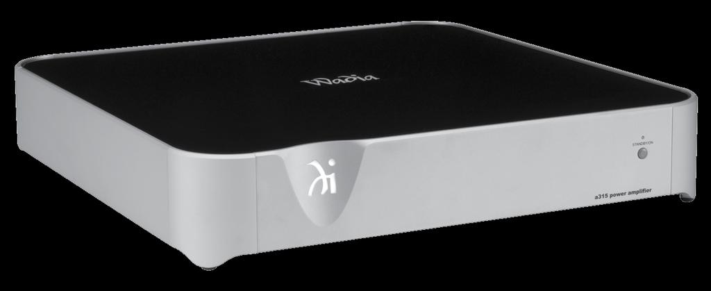
5 Introduction and Performance Features Introduction The Wadia 315 Power Amplifier is one of the finest Digital Power Amplifiers available today. The 150 watts output per channel will drive any high quality Loudspeaker. The a315 reproduction is sonically transparent and absolutely accurate. Performance Features Adaptive Modulation Circuitry Provides full power output over a wide frequency response range with low distortion. Balanced and Unbalanced Inputs Balanced connections allow long cable runs without compromising sound quality. Amplifier and Loudspeaker Protection Built-in Thermal Protection Circuit guards against overheating. The Protection Circuit also actives if Direct Current is detected at the Output Terminals. Custom Binding Posts Patented gold plated output terminals deliver high current output. They accept large diameter wire and spade lugs. Banana plugs may also be used only in the United States and Canada. LED Front Panel Indicator A long life Light Emitting Diodes (LED) are used to indicate the operational status of the a315. Die Cast Aluminium Chassis Maintains cool operating temperatures of the internal circuitry by the heat dissipating properties of the die cast aluminium chassis. The aluminium chassis with illuminated top glass panel is very durable and will retained its appearance for many years to come. Power Supply The a315 Power Amplifier has several regulated power supplies, each one extremely stable to ensure noise free operation even though the power line varies. Trigger Input and Output Connections The Trigger Input and Output connection provides convenient Turn-On/Off of additional Power Amplifiers and/or Source Components. Gold Plated Connectors The Input and Output Connector Contacts are gold plated for superior corrosion resistance and high electrical conductivity. 5
6 Dimensions Dimensions The following dimensions can assist in determining the best location for your a315. There is additional information on the next page pertaining to installing the a315 into cabinets. Front View of the a /8" 45.4cm 2-7/8" 7.3cm 3-3/8" 8.6cm Side View of the a /8" 45.4cm 19-1/8" 48.6cm Rear View of the a /8" 45.4cm 16-7/16" 41.8cm 16-7/16" 41.8cm 6
7 Installation Installation The a315 is designed to be placed upright on a table or shelf, standing on its feet. The ventilation requirements are shown. Always provide adequate ventilation for your a315. Cool operation ensures the longest possible operating life for any electronic instrument. Do not install the a315 directly above a heat generating device, such as another Power Amplifier. Allow at least 6 inches (15.2cm) above the top, 5/8 inches (1.6cm) below the bottom and 2 inch (5.1cm) on each side of the a315, so that airflow is not obstructed. Allow 20 inches (50.8cm) of depth for airflow and cable connections. a315 Front View 2" 5.1cm 6" 15.2cm 2" 5.1cm a315 Side View 6" 15.2cm 21-1/2" 54.6cm 7
8 Rear Panel Connections LEFT OUTPUT Connections for a 4 ohm or 8 ohm Loudspeaker TRIGGER IN receives turn On/Off signals from an audio component TRIGGER OUT sends turn On/Off signals to the next audio Component RIGHT OUTPUT Connections for a 4 ohm or 8 ohm Loudspeaker INPUT MODE switch selects between UNBALanced or BALanced Input UNBALanced INPUTS for an audio cable from a Preamplifier audio output 3 AUTO OFF Power Save Feature is either DISabled or ENAbled Connect the Wadia a315 power cord to a live AC outlet BALanced INPUTS for audio cables from a Preamplifier audio output Caution: The Loudspeaker Output - Negative Terminal Connections are not connected to chassis ground. Do not combine any of the Loudspeaker Ouput Terimals ( + Positive or - Negative) connections together, ground them or connect with another amplifier. 8
9 9
10 Output Terminals When connecting the Loudspeaker Hookup Cables to the a315 Power Amplifier Output Terminals please follow the steps below: 1. Rotate the top of the Output Terminal Post counterclockwise until an opening appears. Refer to figures A and B. 2. Insert the Loudspeaker hookup cable into the Output Terminal Post opening or the cable spade Figure A Opening Figure B lug around the center post of the Output Terminal. Refer to figure C. 3. Rotate the top of the Output Terminal Post clockwise until it is finger tight. Refer to figure D. 4. Place the supplied Wadia Wrench over the top of the Output Terminal and rotate it one quarter of a turn (90 ) to secure the Loudspeaker Cable Figure C Figure D Connection. Do not over Figure E tighten. Refer to figure E. How to Connect Caution: Do not connect the AC Power Cord to the a315 Rear Panel until after the Loudspeaker Connections are made. Failure to observe this could result in Electric Shock. The connection instructions below, together with the a315 Connection Diagram located on the separate folded sheet 1A, is an example of a typical audio system. Your system may vary from this, however the actual components would be connected in a similar manner. For additional information refer to Connector and Cable Information on page For remote AC Power Control of the a315, connect a control cable from the Audio Preamplifier or Source Device Trigger Out to the a315 TRIGGER IN. Note: When a Trigger Control Cable is connected between the a315 and Preamplifier/Source Device, the AUTO OFF Feature is bypassed. Refer to page Connect XLR cables from the Balanced Output (L&R) of an Audio Preamplifier/Source Device to the a315 BALanced INPUTS (Right and Left). Note: An optional hookup is to use unbalanced cable and place the INPUT MODE Switch in the UNBALanced Position. This Wadia a315 Power Amplifier is designed for Loudspeakers with an impedance of 4 ohms or 8 ohms. Connect a single Loudspeaker only to the Right and Left Output Terminals. When connecting Loudspeakers to the a315 it is very important to use cables of adequate size, so there is little to no power loss in the cables. The size is specified in Gauge Numbers or AWG (American Wire Gauge). The smaller the Gauge number, the larger the wire size: Loudspeaker Cable Distance vs Wire Gauge Guide Loudspeaker Impedance 25 feet (7.62 meters) or less 50 feet (15.24 meters) or less 100 feet (30.48 meters) or less 4 Ohms 14AWG 12AWG 10AWG 8 Ohms 16AWG 14AWG 12AWG 3. Prepare the Loudspeaker Hookup Cable for attachment to the a315 Power Amplifier: Bare wire cable ends: Carefully remove sufficient insulation from the cable ends, refer to figures 2, 3 & 4. If the cable is stranded, carefully twist the strands together as tightly as possible. Figure 2 Figure 3 Figure 4 Notes: 1. If desired, the twisted ends can be tinned with solder to keep the strands together. 2. The prepared bare wire cable ends may be inserted into spade lug connectors. 3. Banana plugs are for use in the United States and Canada only. Banana Plugs are for use in the United States and Canada only: 4. Attach the previously prepared bare wire cable ends into the banana plugs and secure the connections. Refer to figure F. 5. Rotate the top of the Output Terminal Post clockwise until it is finger tight. Refer to figure G. Then using the Wadia Wrench, rotate the top of the Output Terminal one quarter of a turn (90 ). Do not over tighten. Refer to figure E. 6. Referring to figure H, connect the Loudspeaker hookup cables with banana plugs into the hole at the end of the a315 Negative and Positive Output Terminals, being careful to observe the correct polarities. Figure F Figure G Figure H Refer to General Information Note 3 on page 4 for additional information. 10
11 Output Terminals and How to Connect WARNING: Loudspeaker terminals are hazardous live and present a risk of electric shock. For additional instruction on making Loudspeaker Connections contact your Wadia Dealer or Wadia Technical Support. 7. Connect the a315 Power Cord to an active AC outlet. Spade Lug or Wire Connections: 8. Connect the Loudspeaker hookup cables to the a315 Negative Output Terminal and Positive Output Terminal, being careful to observe the correct polarities. Insert the spade lug connector or prepared section of the cable end into the terminal side access hole, and tighten the terminal cap until the cable is firmly clamped into the terminals so the lugs or wire cannot slip out. Refer to figures 5 and 6. Figure 5 Figure 6 Refer to General Information Note 3 on page 4 for additional information. WARNING: Loudspeaker terminals are hazardous live and present a risk of electric shock. For additional instruction on making Loudspeaker Connections contact your Wadia Dealer or Wadia Technical Support. 9. Connect the a315 Power Cord to an active AC outlet. 11
12 Output Terminals When connecting the Loudspeaker Hookup Cables to the a315 Power Amplifier Output Terminals please follow the steps below: 1. Rotate the top of the Output Terminal Post counterclockwise until an opening appears. Refer to figures A and B. 2. Insert the Loudspeaker hookup cable into the Output Terminal Post opening or the cable spade Figure A Opening Figure B lug around the center post of the Output Terminal. Refer to figure C. 3. Rotate the top of the Output Terminal Post clockwise until it is finger tight. Refer to figure D. 4. Place the supplied Wadia Wrench over the top of the Output Terminal and rotate it one quarter of a turn (90 ) to secure the Loudspeaker Cable Figure C Figure D Connection. Do not over Figure E tighten. Refer to figure E. How to Connect for Bi-Amp Caution: Do not connect the AC Power Cord to the a315 Rear Panel until after the Loudspeaker Connections are made. Failure to observe this could result in Electric Shock. The connection instructions below, together with the a315 Connection Diagram located on the separate folded sheet 1B, is an example of a typical audio system. Your system may vary from this, however the actual components would be connected in a similar manner. For additional information refer to Connec- tor and Cable Information on page For remote AC Power control of the a315, connect a control cable from the Audio Preamplifier or Source Device Trigger Out to the a315 TRIGGER IN. Note: When a Trigger Control Cable is connected between the a315 and Preamplifier/Source Device, the AUTO OFF Feature is bypassed. Refer to page Connect a control cable from the Amplifier One TRIGGER OUT to Amplifier Two TRIGGER IN. Note: There is approximately a one-half second delay added to the TRIGGER OUT signal in a315 Power Amplifier to reduce the strain on the AC Power Line. This will delay the Turn-On of the second a315 Power Amplifier. 3. Connect audio cables from the Unbalanced Output (L&R) of an Audio Preamplifier/Source Device to the amplifier one UNBALanced INPUTS (Right and Left). Note: Place the INPUT MODE Switch to the UN- BALanced position. 4. Connect balanced XLR cables from the Balanced Output (L&R) of an Audio Preamplifier/Source Device to the amplifier two BALanced INPUTS (Right and Left). Note: Place the INPUT MODE Switch to the BALanced position. The Wadia a315 Power Amplifier is designed for Loudspeakers with an impedance of 4 ohms or 8 ohms. Connect a single Loudspeaker only to the Output Terminals. When connecting Loudspeakers to the a315 it is very important to use cables of adequate size, so there is little to no power loss in the cables. The size is specified in Gauge Numbers or AWG (American Wire Gauge). The smaller the Gauge number, the larger the wire size: Loudspeaker Cable Distance vs Wire Gauge Guide Loudspeaker Impedance 25 feet (7.62 meters) or less 50 feet (15.24 meters) or less 100 feet (30.48 meters) or less 4 Ohms 14AWG 12AWG 10AWG 8 Ohms 16AWG 14AWG 12AWG 5. Prepare the Loudspeaker Hookup Cable for attachment to the a315 Power Amplifier: Bare wire cable ends: Carefully remove sufficient insulation from the cable ends, refer to figures 2, 3 & 4. If the cable is stranded, carefully twist the strands together as tightly as possible. Figure 2 Figure 3 Figure 4 Notes: 1. If desired, the twisted ends can be tinned with solder to keep the strands together. 2. The prepared bare wire cable ends may be inserted into spade lug connectors. 3. Banana plugs are for use in the United States and Canada only. Banana Plugs are for use in the United States and Canada only: 6. Attach the previously prepared bare wire cable ends into the banana plugs and secure the connections. Refer to figure F. 7. Rotate the top of the Output Terminal Post clockwise until it is finger tight. Refer to figure G. Then using the Figure G Wadia Wrench, rotate the top of the Figure F 12
13 How to Connect for Bi-Amp Output Terminal one quarter of a turn (90 ). Do not over tighten. Refer to figure E. 8. Referring to figure H, connect the Loudspeaker hookup cables with banana plugs into the hole at the end of the a315 Negative and Positive Output Terminals, being careful to observe the correct polarities. Figure H Refer to General Information Note 3 on page 4 for additional information. WARNING: Loudspeaker terminals are hazardous live and present a risk of electric shock. For additional instruction on making Loudspeaker Connections contact your Wadia Dealer or Wadia Technical Support. 9. Connect the a315 Power Cord to an active AC outlet. Refer to General Information Note 3 on page 4 for additional information. WARNING: Loudspeaker terminals are hazardous live and present a risk of electric shock. For additional instruction on making Loudspeaker Connections contact your Wadia Dealer or Wadia Technical Support. 11. Connect the a315 Power Cord to an active AC outlet. Spade Lug or Wire Connections: 10. Connect the Loudspeaker hookup cables to the a315 Negative Output Terminal and Positive Output Terminal, being careful to observe the correct polarities. Insert the spade lug connector or prepared section of the cable end into the terminal side access hole, and tighten the terminal cap until the cable is firmly clamped into the terminals so the lugs or wire cannot slip out. Refer to figures 5 and 6. Figure 5 Figure 6 13
14 Front Panel Display and Push-button STANDBY/ON Push-button with indicator, switches the a315 ON or OFF (Standby) 14
15 How to Operate How to Operate Power On/Off Momentarily press the POWER Push-button to switch the a315 On or Off. Refer to figure 7. 3 Note: There must be a Trigger Control Connection between the a315 and the Audio Preamplifier or Source Device, in order for the remote Figure 7 power turn-on to function. Input Mode Switch The Input Mode Switch, which is located on the Rear Panel of the a315, allows selection of either the BALanced or UNBALanced Inputs. Refer to figure 9. Figure 9 Auto Off The a315 incorporates a Power Save Feature to automatically switch power Off to the Power Amplifier approximately 30 minutes after there has been an absence of an audio input signal. Note: If the Power Save Feature has activated and switched the a315 Off, the Power Save Feature can be reset by momentarily pressing the STANDBY/ON Push-button. When there is a Trigger Input Connection between the a315 and a Preamplifier or Source Device, the Power Save Feature in the a315 is bypassed. With the a315 connected (via Trigger Control) to a Preamplifier (Source Device) with the Power Save Feature and the feature is active, the a315 will switch Off with the Preamplifier (Source Device) after a period of inactivity. There may be times when it would be desirable to bypass the Power Save Feature, which by default is active. This can be implemented by placing the AUTO OFF Switch, located on the a315 Rear Panel, in the DIS (Disable) position. Figure 8 Refer to figure 8: 15

16 16
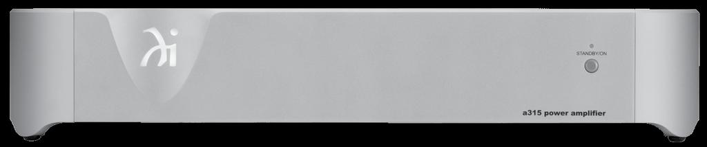

17 Photos 17
18 Specifications Specifications Power Output Minimum sine wave continuous average power output per channel, with both channels operating at 0.5% Total Harmonic Distortion is: 150 watts into 8 ohm load 250 watts into 4 ohm load Output Load Impedance 8 or 4 ohms Rated Power Band 20Hz to 20,000Hz Total Harmonic Distortion 0.1% maximum harmonic distortion at any level from 250 milliwatts to one-half of rated power output, 20Hz to 20,000Hz. 0.5% maximum harmonic distortion at any level from one-half to full rated power output, 20Hz to 20,000Hz. Dynamic Headroom 1dB, 8 ohm load 1.6dB, 4 ohm load Frequency Response +0, -0.5dB from 20Hz to 20,000Hz +0, -3.0dB from 10Hz to 70,000Hz Input Sensitivity (for rated output) 2.4 Volts Balanced 1.2 Volts Unbalanced Signal To Noise Ratio (A-Weighted) 90dB (112dB below rated output) Balanced 88dB (110dB below rated output) Unbalanced Intermodulation Distortion 0.1% maximum if the instantaneous peak power output does not exceed the rated power output, for any combination of frequencies from 20Hz to 20,000Hz. Wide Band Damping Factor Greater than 320, 8 Ohm load Greater than 160, 4 Ohm load Input Impedance 10,000 ohms Balanced 10,000 ohms Unbalanced Voltage Gain 29dB Trigger Input 5-15VDC, less than 1mA Trigger Output 12VDC, 50mA maximum Output is delayed 0.2 seconds from turn On General Specifications Power Requirement 100V - 240V ~ 50/60Hz at 130 Watts Standby: less than 0.5 watt Note: All Specifications are with AC Line voltage of 120V. Overall Dimensions Width is 17-7/8 inches (45.4cm) Height is 3-3/8 inches (8.6cm) including feet Depth is 20 inches (50.8cm) including the Cables Weight 27 pounds (12.2 kg) net, 31.5 pounds (14.3 kg) in shipping carton Shipping Carton Dimensions Width is 22-1/2 inches (57.2cm) Height is 8-1/8 inches (20.6cm) Depth is 22-1/2 inches (57.2cm) 18
19 Packing Instructions Packing Instructions In the event it is necessary to repack the equipment for shipment, the equipment must be packed exactly as shown below. It is very important to ensure the proper equipment location between the bottom and top foam pads. Failure to do this will result in shipping damage. Use the original shipping carton and interior parts only if they are all in good serviceable condition. If a shipping carton or any of the interior part(s) are needed, please call or write Customer Service Department of Wadia. Refer to page 4. Please see the Part List for the correct part numbers. Quantity Part Number Description Shipping carton only Top foam pad Bottom foam pad TOP FOAM PAD UNIT OWNER S MANUAL AC POWER CORD BOTTOM FOAM PAD SHIPPING CARTON 19
20 Wadia Digital, LLC 2 Chambers Street Binghamton, NY The continuous improvement of its products is the policy of Wadia Digital who reserve the right to improve design without notice. Printed in the U.S.A. Wadia Digital Part No
MC75 Tube Power Amplifier Owner s Manual
 McIntosh Laboratory, Inc. 2 Chambers Street Binghamton, New York MC75 Tube Power Amplifier Owner s Manual 13903-2699 Phone: 607-723-3512 www.mcintoshlabs.com 2 The lightning flash with arrowhead, within
Power Amplifier. MC252 Owner s Manual
 Power Amplifier MC252 Owner s Manual McIntosh Laboratory, Inc. 2 Chambers Street Binghamton, New York 13903-2699 Phone: 607-723-3512 FAX: 607-724-0549 The lightning flash with arrowhead, within an equilateral
Power Amplifier. MC501 Owner s Manual
 Power Amplifier MC501 Owner s Manual McIntosh Laboratory, Inc. 2 Chambers Street Binghamton, New York 13903-2699 Phone: 607-723-3512 FAX: 607-724-0549 The lightning flash with arrowhead, within an equilateral
MC205 Power Amplifier Owner s Manual
 McIntosh Laboratory, Inc. 2 Chambers Street Binghamton, New York MC205 Power Amplifier Owner s Manual 13903-2699 Phone: 607-723-3512 www.mcintoshlabs.com 2 The lightning flash with arrowhead, within an
MC302 Power Amplifier Owner s Manual
 McIntosh Laboratory, Inc. 2 Chambers Street Binghamton, New York MC302 Power Amplifier Owner s Manual 13903-2699 Phone: 607-723-3512 www.mcintoshlabs.com 2 The lightning flash with arrowhead, within an
Power Controller. MPC1500 Owner s Manual. Torus Power Technology under license from Plitron Manufacturing Inc.
 Power Controller MPC1500 Owner s Manual Torus Power Technology under license from Plitron Manufacturing Inc. McIntosh Laboratory, Inc. 2 Chambers Street Binghamton, New York 13903-2699 Phone: 607-723-12
MC312 Power Amplifier Owner s Manual
 McIntosh Laboratory, Inc. 2 Chambers Street Binghamton, New York MC312 Power Amplifier Owner s Manual 13903-2699 Phone: 607-723-3512 www.mcintoshlabs.com Important Safety Information is supplied in a separate
MC58 Eight Channel Power Amplifier
 Owner s Manual MC58 Eight Channel Power Amplifier MC58 McIntosh Laboratory, Inc. 2 Chambers Street Binghamton, New York 13903-2699 Phone: 607-723-3512 FAX: 607-724-0549 The lightning flash with arrowhead,
2BSST POWER AMPLIFIER OWNER S MANUAL
 2BSST POWER AMPLIFIER OWNER S MANUAL IMPORTANT SAFETY INSTRUCTIONS The lightning flash with arrowhead symbol within an equilateral triangle, is intended to alert the user to the presence of un-insulated
A Channel Amplifier
 Installation Manual A2150 2 Channel Amplifier Table of Contents Installation Requirements and Recommendations 1 What s included 1 Speaker Wire Recommendations 1 Setup 2 Rack Mounting 2 Individually Protected
MC462 Quad Balanced Power Amplifier Owner s Manual
 McIntosh Laboratory, Inc. 2 Chambers Street Binghamton, New York MC462 Quad Balanced Power Amplifier Owner s Manual 13903-2699 Phone: 607-723-3512 www.mcintoshlabs.com Important Safety Information is supplied
M-300 Mono power amplifier User s guide
 M-300 Mono power amplifier User s guide M-300 Mono power amplifier User s guide Specifications: Contents: Power output: 8Ω: 290W, 0.01% THD SPECIFICATIONS Page 2 Input impedance: Gain: 4Ω: 580W, 0.01%
REVAMP4100 Instruction manual
 REVAMP4100 Instruction manual REVAMP4100 Instruction manual 3 REVAMP4100 manual 4 CLASS-D POWER AMPLIFIER IMPORTANT SAFETY INSTRUCTIONS 1. Read these instructions 2. Keep these instructions 3. Heed all
plifier D-501 otion Am Tactile M
 Tactile Motion Amplifier D-501 IMPORTANT SAFETY INSTRUCTIONS WARNING: 1. Read and keep these instructions for future reference. 2. Do not use this apparatus near water. 3. Clean only with a dry cloth.
ECA COMMERCIAL AMPLIFIER OWNER S MANUAL ECA-70MIXAMP V / 70V / 4Ω Amplifier ECA-70MIXAMP-1-60 OUTPUT LEVEL POWER MASTER MIC 1
 OWNER S MANUAL ECA COMMERCIAL AMPLIFIER ECA-MIXAMP--6 V / V / Ω Amplifier TEMP PROT OUTPUT LEVEL ECA-MIXAMP--6 6 POWER MIC MIC MIC MIC AUX AUX BASS TREBLE 5 5 5 5 5 6 6 6 6 6 MASTER 5 6 ON OFF + - + -
REVAMP4120T Instruction manual
 REVAMP4120T Instruction manual REVAMP4120T Instruction manual 3 REVAMP4120T manual 4 CLASS-D POWER AMPLIFIER IMPORTANT SAFETY INSTRUCTIONS 1. Read these instructions 2. Keep these instructions 3. Pay
Big Bang. B B O w n e r s M a n u a l. Power Amplifiers. SpeakerCraft BB2125 POWER ACTIVE PROTECTION L
 Big Bang Power Amplifiers SpeakerCraft BB2125 ACTIVE POWER PROTECTION L R B B 2 1 2 5 O w n e r s M a n u a l SAFETY INSTRUCTIONS APPLICABLE FOR USA, CANADA OR WHERE APPROVED FOR USAGE CAUTION: To reduce
R-Series R235LS 2-Channel Power Amplifier with Local Source Switching
 R-Series R235LS 2-Channel Power Amplifier with Local Source Switching User s Manual On Off R235LS POWER A MPLIFIER IMPORTANT SAFEGUARDS WARNING TO REDUCE THE RISK OF FIRE OR ELECTRIC SHOCK, DO NOT EXPOSE
HTA125A/250A. Power Amplifiers. Installation & Use Manual
 HTA125A/250A Power Amplifiers Installation & Use Manual Specifications subject to change without notice. 2010 Bogen Communications, Inc. All rights reserved. 54-5832-04B 1011 NOTICE: Every effort was made
XR50 Loudspeaker System Owner s Manual
 McIntosh Laboratory, Inc. 2 Chambers Street Binghamton, New York XR50 Loudspeaker System Owner s Manual 13903-2699 Phone: 607-723-3512 www.mcintoshlabs.com WARNING - TO REDUCE RISK OF FIRE OR ELECTRICAL
KLASIK NEAR FIELD ACTIVE STUDIO MONITOR
 USER S MANUAL KLASIK NEAR FIELD ACTIVE STUDIO MONITOR CONTENTS page INTRODUCTION GENERAL INFORMATION 3 REAR PANEL REAR PANEL 4 INPUTS 5 SWITCHES 5 TECHNICAL SPECIFICATIONS TECHNICAL SPECIFICATIONS 7 SAFETY
Opus 21 s80 Integrated Amplifier Owner's Manual
 Opus 21 s80 Integrated Amplifier Owner's Manual r e s o l u t i o n From all of us at Resolution Audio, thank you for choosing the Opus 21 s80 amplifier. We went to great lengths to design and produce
Primare A33.2 Amplifier User Guide
 > Primare A33.2 Amplifier User Guide > Preface CAUTION RISK OF ELECTRIC SHOCK DO NOT OPEN CAUTION: To reduce the risk of electrical shock do not remove cover (or back). No user serviceable parts inside.
Important Safety Information
 OWNER'S MANUAL Important Safety Information 1. Read these instructions. 2. Keep these instructions. 3. Heed all warnings. 4. Follow all instructions. 5. Do not use this apparatus near water. 6. Clean only
875HT OWNER S MANUAL
 875HT OWNER S MANUAL 875HT EIGHT CHANNEL POWER AMPLIFIER Table of Contents Important Safety Instructions General Introduction Page 1 Introduction Description Shipping Box & Packing Materials Installation
WX-1 & WX-3 OPERATING MANUAL AND USER GUIDE. Professional Power Amplifier. WX-1 and WX-3.indd :23:16
 WX-1 & WX-3 Professional Power Amplifier OPERATING MANUAL AND USER GUIDE 3 www.wharfedalepro.com WX-1 and WX-3.indd 1 2014-7-16 10:23:16 TABLE OF CONTENTS TABLE OF CONTENTS... 1 IMPORTANT WARNINGS & SAFETY
DPA-1.2. Instruction Manual. 2 Channel Amplifier with Auto A/B Selector DPA-1.2 DPA-1.2 POWER SERIAL # LINE INPUT SENSING SPEAKER B OUT
 POWER Russound DPA-1.2 Instruction Manual 2 Channel Amplifier with Auto A/B Selector NEWMARKET, NH USA DPA-1.2 Russound 68835 Conforms to UL 6500 Certified to CSA C22.2 No1-94 DPA-1.2 Tested to Comply
Loudspeaker System. XCS1K Owner s Manual
 Loudspeaker System XCS1K Owner s Manual McIntosh Laboratory, Inc. 2 Chambers Street Binghamton, New York 13903-2699 Phone: 607-723-3512 FAX: 607-724-0549 WARNING - TO REDUCE RISK OF FIRE OR ELECTRICAL
A32. f u l l y b a l a n c e d p o w e r a m p l i f i e r. user guide
 A32 f u l l y b a l a n c e d p o w e r a m p l i f i e r user guide Welcome! Welcome to the Primare A32 Amplifier! The A32 is a modular power amplifier designed as the ideal output stage in a home theatre
User Manual LMS-325 Line Monitor Speaker
 User Manual LMS-325 Line Monitor Speaker 9350-7490-000 Rev E 10/2010 PROPRIETARY NOTICE The product information and design disclosed herein were originated by and are the property of Bosch Security Systems,
Classic Series Public Address Amplifiers C10 & C20 Models
 Classic Series Public Address Amplifiers C10 & C20 Models Installation and Use Manual 2009 Bogen Communications, Inc. All rights reserved. Specifications subject to change without notice. 54-5978-01C 1106
IMPORTANT SAFETY INSTRUCTIONS
 Addendum IMPORTANT SAFETY INSTRUCTIONS Read these instructions. Keep these instructions. Heed all warnings. Follow all instructions. Do not use this apparatus near water. Mains powered apparatus shall
AV25-2 User Manual. 1 Important safety instructions
 AV25-2 User Manual 1 Important safety instructions 1. Please read carefully prior to product installation or operation. 2. Read these instructions. 3. Keep these instructions. 4. Heed all warnings. 5.
Lanen Series 21 from Prodipe SB21 Lanen Instrument Mic. User Manual SB21 Lanen Sax / Brass / Percussion
 Lanen Series 21 from Prodipe SB21 Lanen Instrument Mic User Manual SB21 Lanen Sax / Brass / Percussion Safety Information Thank you for purchasing this digital appliance. To ensure perfect operation and
3400 Watt Stereo Power Amplifier
 3400 Watt Stereo Power Amplifier OWNER'S MANUAL Copyright 2014, Samson Technologies Corp. v1.1 Samson Technologies Corp. 45 Gilpin Ave Hauppauge, NY 11788 www.samsontech.com Important Safety Information
Classic Series Public Address Amplifiers C10 & C20 Models
 Classic Series Public Address Amplifiers C10 & C20 Models Installation and Use Manual 2009 Bogen Communications, Inc. All rights reserved. Specifications subject to change without notice. 54-5978-01B 0901
CLASS D STEREO AMPLIFIER 60 WPC. Model: APA102 User Manual
 CLASS D STEREO AMPLIFIER 60 WPC Model: APA102 User Manual CAUTION RISK OF ELECTRICAL SHOCK DO NOT OPEN CAUTION: TO REDUCE THE RISK OF ELECTRIC SHOCK, DO NOT REMOVE THE COVER. NO USER SERVICABLE PARTS INSIDE.
IMPORTANT SAFETY INSTRUCTIONS
 WR-1 Version 1 IMPORTANT SAFETY INSTRUCTIONS 1. 2. 3. 4. 5. 6. 7. 8. 9. Read these instructions. Keep these instructions. Heed all warnings. Follow all instructions. Do not use this apparatus near water.
STEREO TUBE POWER AMPLIFIER
 STEREO TUBE POWER AMPLIFIER STEREO TUBE REAMPLIFIER USER S MANUAL S. T. I N N O V A T O R S - S O F I A 1 5 0 5, 1, T Z A R I C H I N A S T R., T E L. 8 7 0-2 1-5 6, F A X. 9 7 3-3 7-2 7 2 3 Table of Contents
AV30MX-2 Operation Manual
 AV30MX-2 Operation Manual 1 Important safety instructions 1. Please read carefully prior to product installation or operation. 2. Read these instructions. 3. Keep these instructions. 4. Heed all warnings.
Dual Alarm Clock Radio with Digital Tuning NRC-174. Instruction Manual Please read carefully before use and keep for future reference.
 Dual Alarm Clock Radio with Digital Tuning NRC-174 Instruction Manual Please read carefully before use and keep for future reference. Important Safety Information CAUTION RISK OF ELECTRIC SHOCK DO NOT
Lanen True Diversity UHF Systems For electric and bass guitars: GB21 For Series 21 mics: UHF21. User Manual GB21 receiver/uhf21 transmitter
 Lanen True Diversity UHF Systems For electric and bass guitars: GB21 For Series 21 mics: UHF21 User Manual GB21 receiver/uhf21 transmitter Safety Information Thank you for purchasing this digital appliance.
Safety Precautions. Important Safety Instructions
 Thank you for purchasing this digital piano. For optimal operation and security, please read this manual carefully and keep it for future reference. Safety Precautions The lightning flash with arrowhead
léìë=on ëpm=fåíéöê~íéç=^ãéäáñáéê lïåéêdë=j~åì~ä êéëçäìíáçå
 léìë=on ëpm=fåíéöê~íéç=^ãéäáñáéê lïåéêdë=j~åì~ä êéëçäìíáçå From all of us at Resolution AV, thank you for choosing the Opus 21 s30 amplifier. We went to great lengths to design and produce an integrated
A WORLD OF LISTENING WARNING: TO PREVENT FIRE OR ELECTRIC SHOCK HAZARD, DO NOT EXPOSE THIS PRODUCT TO RAIN OR MOISTURE.
 DDR-3 FM RDS/DAB digital radio A WORLD OF LISTENING THE LIGHTNING FLASH AND ARROW- HEAD WITHIN THE TRIANGLE IS A WARNING SIGN ALERTING YOU OF DANGEROUS VOLTAGE INSIDE THE RADIO. WARNING: TO PREVENT FIRE
Model CC4041. CC Series Amplifier. Installation and Use Manual
 BASS 0 TREBLE 0-12 +12-12 +12 INPUT 1 INPUT 2 INPUT 3 INPUT 4 PEAK SIGNAL POWER POWER CC Series Amplifier Model CC4041 Installation and Use Manual 2012 Bogen Communications, Inc. All rights reserved. Specifications
1695T Black Magick. User Manual
 1695T Black Magick User Manual All contents c Absara Audio LLC 2014 1. Important Safety Information The triangle surrounding an exclamation mark alerts users to the presence of important warnings or information.
3BSST 4BSST POWER AMPLIFIER OWNER S MANUAL UPDATED
 3BSST 4BSST POWER AMPLIFIER OWNER S MANUAL UPDATED 007-01-9 3Bsst & 4Bsst POWER AMPLIFIERS GENERAL INFORMATION Introduction Thank you for choosing an SST SERIES Stereo Power Amplifier. Bryston welcomes
INSTALLATION MANUAL ECA-70VMINI-60W ECA-70VMINI-60W L VOLUME SPEAKER OUTPUTS 12VDC IN + L+ L- GND R+ R- S GND GND Tx Rx
 INSTALLATION MANUAL ECA-70VMINI-60W ECA-70VMINI-60W L VOLUME R 12VDC IN BALANCED IN STEREO IN UNBALANCED IN SERVICE STATUS IR RS-232 + L+ L- GND R+ R- S GND GND Tx Rx SPEAKER OUTPUTS + page 2 CAUTION Risk
HARMONY SINGER 2. Battery-Powered Vocal Effects Stompbox with Guitar-Controlled Harmony, Reverb and Tone. User Manual
 HARMONY SINGER 2 Battery-Powered Vocal Effects Stompbox with Guitar-Controlled Harmony, Reverb and Tone User Manual 2 Harmony Singer 2 User Manual Important Safety Instructions Terminals marked with this
User Guide. Wideband 4-channel Auto Gain-Control Antenna Divider
 User Guide AD-708 Wideband 4-channel Auto Gain-Control Antenna Divider All rights reserved. Do not copy or forward without prior approvals MIPRO. Specifications and design subject to change without notice.
REVAMP2250 Instruction manual
 REVAMP2250 Instruction manual REVAMP2250 Instruction manual 3 REVAMP2250 Manual 4 CLASS-D POWER AMPLIFIER IMPORTANT SAFETY INSTRUCTIONS 1. Read these instructions 2. Keep these instructions 3. Heed all
10 WATT GUITAR COMBO
 10 WATT GUITAR COMBO Caution: To reduce the hazard of electrical shock, do not remove cover or back. No user serviceable parts inside. Please refer all servicing to qualified personnel. WARNING: To reduce
STEREO POWER AMPLIFIER OWNER MANUAL PR-150 DESIGNED IN U.K. PDF created with FinePrint pdffactory trial version
 STEREO POWER AMPLIFIER OWNER MANUAL PR-150 DESIGNED IN U.K. INTRODUCTION Congratulations on your purchase of MA PR-150 Stereo Power Amplifier. The performance of PR-150 is perfect for any audio application,
Mini-Z. Manual. Model: ZA-21.
 Mini-Z Manual Model: ZA-21 www.drzamps.com This symbol warns the user of dangerous voltage levels localized within the enclosure. This symbol advises the user to read all accompanying literature for safely
MIC MECHANIC 2. Ultra-Simple Battery-Powered Vocal Effects Stompbox with Echo, Reverb and Pitch Correction. User Manual
 MIC MECHANIC 2 Ultra-Simple Battery-Powered Vocal Effects Stompbox with Echo, Reverb and Pitch Correction User Manual 2 MIC MECHANIC 2 User Manual Important Safety Instructions Terminals marked with this
IMPORTANT SAFETY INSTRUCTIONS
 WR-11 Version 1 IMPORTANT SAFETY INSTRUCTIONS 1. Read these instructions. 2. Keep these instructions. 3. Heed all warnings. 4. Follow all instructions. 5. Do not use this apparatus near water. 6. Clean
Classic Series Amplifiers C35, C60, & C100 Models
 Classic Series Amplifiers C35, C60, & C100 Models Installation and Use Manual 2009 Bogen Communications, Inc. All rights reserved. Specifications subject to change without notice. 54-5979-02E 1203 Notice:
MODEL A1. PackLite TM POWER AMPLIFIER
 MODEL A1 PackLite TM POWER AMPLIFIER Svenska Nederlands Italiano Français Español Deutsch Dansk English Important Safety Instructions 1. Read these instructions. 2. Keep these instructions. 3. Heed all
w i t h T A B L E O F C O N T E N T S Safety Information 2 Certifications/Standards 3
 M ono Pow er Amplifier w i t h Information T A B L E O F C O N T E N T S Safety Information 2 Certifications/Standards 3 Warranty 4 Unpacking 4 Setup and Placement 4 Rear Panel Connections 5 Tips for Operation
MAZ 18/MAZ 38. Manual. Model: ZA-8 / ZA-5.
 MAZ 18/MAZ 38 Manual Model: ZA-8 / ZA-5 www.drzamps.com This symbol warns the user of dangerous voltage levels localized within the enclosure. This symbol advises the user to read all accompanying literature
SAGA PRO SERIES STEREO POWER AMPLIFIER OPERATION MANUAL
 SAGA PRO SERIES STEREO POWER AMPLIFIER OPERATION MANUAL INSTALLATION Use care in unpacking the amplifier, and be sure to save the carton and packing materials so that you can use them for moving, storing,
A-16D A-Net Distributor
 A-16D A-Net Distributor For use with the Personal Monitor Mixing System Information in this document is subject to change. All rights reserved. Copyright 2003 Aviom, Inc. Printed in USA Document Rev. 1.03
PREZONE1 Instruction manual
 PREZONE1 Instruction manual PREZONE1 manual PREZONE1 Instruction manual 3 4 Preamplifiers IMPORTANT SAFETY INSTRUCTIONS Read these instructions - All the safety and operating instructions should be read
Model CC4052. CC Series Amplifier. Installation and Use Manual
 CC Series Amplifier Model CC4052 Installation and Use Manual 2012 Bogen Communications, Inc. All rights reserved. Specifications subject to change without notice. 54-2216-01A 1303 NOTICE: Every effort
DA216S DISTRIBUTION AMPLIFIER
 DISTRIBUTION AMPLIFIER IMPORTANT SAFETY INSTRUCTIONS 1. Read these instructions. 2. Keep these instructions. 3. Heed all warnings. 4. Follow all instructions. 5. Do not use this apparatus near water. 6.
400M. Series. Owner s Manual. Mono Power Amplifier
 400M Mono Power Amplifier Series Owner s Manual 400M Neo Series Owner s Manual Important Safety Instructions 1. Read these instructions. 2. Keep these instructions. 3. Heed all warnings. 4. Follow all
Spider. Pilot s Handbook Manuel de pilotage Pilotenhandbuch Pilotenhandboek Manual del Piloto 取扱説明書
 Spider IV Pilot s Handbook Manuel de pilotage Pilotenhandbuch Pilotenhandboek Manual del Piloto 取扱説明書 Get free lessons and tones! Join Spider Online! www.line6.com/spideronline 40-00-0186 Pilot s Handbook
Dual Terror Owners Manual
 Dual Terror Owners Manual Orange Amplifiers OMEC House 108 Ripon Way Borehamwood Hertfordshire WD6 2JA ENGLAND Tel: +44 20 8905 2828 Fax: +44 20 8905 2868 info@omec.com Orange USA 2065 Peachtree Industrial
Owner s Manual. MOON Series W5.3 SE. Stereo Power Amplifier
 Owner s Manual MOON Series W5.3 SE Stereo Power Amplifier Important Safety Instructions 1. Read these instructions. 2. Keep these instructions. 3. Heed all warnings. 4. Follow all instructions. 5. Do not
SVS SoundPath Wireless Audio Adapter Owner s Manual
 SVS SoundPath Wireless Audio Adapter Owner s Manual SVS SoundPath Wireless Audio Adapter Thank you for choosing SVS! The SoundPath Wireless Audio Adapter reduces subwoofer cable clutter without sacrificing
Carmen Ghia. Manual. Model: ZA-07.
 Carmen Ghia Manual Model: ZA-07 www.drzamps.com This symbol warns the user of dangerous voltage levels localized within the enclosure. This symbol advises the user to read all accompanying literature for
Page 1 of 6 Systems Inc.
 Page 1 of 6 This symbol indicates that dangerous voltage constituting a risk of electric shock is present within this unit. This symbol indicates that there are important operating and maintenance instructions
arthur ART48 - YELLOW ACOUSTIC FIDELITY USER MANUAL Assembling instruction on ART48-L/Rmast manual
 V2 ACOUSTIC FIDELITY arthur ART48 - YELLOW USER MANUAL Assembling instruction on ART48-L/Rmast manual WARNINGS PRECAUTIONS WARNINGS Read carefully this manual and follow these precautions before operating
Spider Valve. Pilot s Guide Manuel de pilotage Pilotenhandbuch Pilotenhandboek Manual del Piloto 取扱説明書
 Spider Valve MKII Pilot s Guide Manuel de pilotage Pilotenhandbuch Pilotenhandboek Manual del Piloto 取扱説明書 40-00-0233 Pilot s Handbook available @ www.line6.com/manuals Rev D Important Safety Instructions
SPECIAL 6. 6-Watt Vacuum Tube Guitar Amplifier. User Manual
 SPECIAL 6 6-Watt Vacuum Tube Guitar Amplifier User Manual Table of Contents Table of Contents... 3 Product Safety Information...4 Panel Functions... 5 Technical Specifications... 8 Important Safety Instructions
a u d i o p h i l e d i g i t a l - t o - a n a l o g u e c o n v e r t e r user guide
 DAC30 a u d i o p h i l e d i g i t a l - t o - a n a l o g u e c o n v e r t e r user guide Welcome! Welcome to the Primare DAC30! Your DAC30 is a fully balanced audiophile digitalto-analogue converter,
ENGLISH THANK YOU! OR15. Thank you for choosing Orange. You are now a member of the Legendary British Guitar Amplifier owners club!
 1 THANK YOU! Thank you for choosing Orange. You are now a member of the Legendary British Guitar Amplifier owners club! Since 1968 when the company was founded, Orange has been a pioneering force in the
Z-LUX. Manual. Model: ZA-38.
 Z-LUX Manual Model: ZA-38 www.drzamps.com This symbol warns the user of dangerous voltage levels localized within the enclosure. This symbol advises the user to read all accompanying literature for safely
Galileo. Prestige Italian Audio Rack Table OWNER S MANUAL
 Galileo Prestige Italian Audio Rack Table OWNER S MANUAL IMPORTANT SAFETY INFORMATION Do not disassemble any part of the product. Do not use any part of the product for other purposes. For service and
XRT30. Loudspeaker System
 Owner s Manual XRT30 Loudspeaker System XRT30 McIntosh Laboratory, Inc. 2 Chambers Street Binghamton, New York 13903-2699 Phone: 607-723-3512 FAX: 607-724-0549 WARNING - TO REDUCE RISK OF FIRE OR ELECTRICAL
1668RT Jupiter. User Manual
 1668RT Jupiter User Manual All contents c Absara Audio LLC 2015 1. Important Safety Information The triangle surrounding an exclamation mark alerts users to the presence of important warnings or information.
PAM 1270 MULTI-ZONE AMPLIFIER OWNER S MANUAL WARRANTY & REPAIR
 WARRANTY & REPAIR ll OSD AUDIO electronics have (2) year Limited Warranty against defects in materials and workmanship. Proof of purchase must accompany all claims. During the warranty period OSD AUDIO
9B SST 2 OWNER S MANUAL
 9B SST 2 OWNER S MANUAL Table of Contents General Introduction............................ Page 1 Description Packing Materials Installation and Ventilation Speaker Wires................................
XD-V30 Digital Wireless System
 XD-V30 Digital Wireless System Pilot s Handbook Manuel de pilotage Pilotenhandbuch Pilotenhandboek Manual del Piloto 取扱説明書 See www.line6.com/manuals for Advance Guide 40-00-0286 Advanced Users Guide available
ENGLISH THANK YOU! DARK TERROR. Thank you for choosing Orange. You are now a member of the Legendary British Guitar Amplifier owners club!
 ENGLISH THANK YOU! Thank you for choosing Orange. You are now a member of the Legendary British Guitar Amplifier owners club! Since 1968 when the company was founded, Orange has been a pioneering force
Owners Manual Excite X14A
 Owners Manual Excite X14A Introduction Introduction Important safety instructions The lightning flash with an arrowhead symbol within an equilateral triangle, is intended to alert the user to the presence
CR31. Companion. Instruction Manual
 CR31 Companion Instruction Manual 910-244700-001 IMPORTANT SAFETY INSTRUCTION PLEASE READ CAREFULLY ALL THE FOLLOWING IMPORTANT SAFEGUARDS THAT ARE APPLICABLE TO YOUR EQUIPMENT 1. Read Instructions - All
Copyright 2017, Samson Technologies Corp. v1.1. Samson Technologies Corp. 278-B Duffy Ave Hicksville, NY
 OWNER'S MANUAL Copyright 2017, Samson Technologies Corp. v1.1 Samson Technologies Corp. 278-B Duffy Ave Hicksville, NY 11801 www.samsontech.com Important Safety Information ATTENTION RISQUE DE CHOC ÉLECTRONIQUE
Instruction Manual Please read carefully before use and keep for future reference.
 Easy-Read Dual Alarm Clock with Daily Repeat, Bluetooth, and USB Charge Port NRC-181 Instruction Manual Please read carefully before use and keep for future reference. Important Safety Information CAUTION
ENGLISH THANK YOU! TH100. Thank you for choosing Orange. You are now a member of the Legendary British Guitar Amplifier owners club!
 1 THANK YOU! Thank you for choosing Orange. You are now a member of the Legendary British Guitar Amplifier owners club! Since 1968 when the company was founded, Orange has been a pioneering force in the
EPA152/252/502. User Manual.
 EPA152/252/502 User Manual www.audac.eu ADDITIONAL INFORMATION This manual is put together with much care, and is as complete as could be on the publication date. However, updates on the specifications,
GOLD NOTE PA-1175 PA Stereo Power Amplifier. Stereo - Bridged Mono OWNER S MANUAL
 GOLD NOTE PA-1175 DF PA-1175 Stereo Power Amplifier Stereo 175W@8Ohm - Bridged Mono 350W@8Ohm OWNER S MANUAL IMPORTANT SAFETY INFORMATION CAUTION: TO REDUCE THE RISK OF ELECTRIC SHOCK, DO NOT REMOVE COVER
Important safety instructions
 MMR-88 Version 1 Important safety instructions 1. 2. 3. 4. 5. 6. 7. 8. 9. Please read these instructions carefully. Please keep these instructions for future reference. Heed all warnings Follow all instructions
Spider IV 15. Pilot s Handbook Manuel de pilotage Pilotenhandbuch Pilotenhandboek Manual del Piloto 取扱説明書
 Spider IV 15 Pilot s Handbook Manuel de pilotage Pilotenhandbuch Pilotenhandboek Manual del Piloto 取扱説明書 Get free lessons and tones! Join Spider Online! www.line6.com/spideronline 40-00-0187 Pilot s Handbook
CANARY AUDIO. Power Amplifier CA-309 OWNER S MANUAL. Handcrafted in California MADE IN USA
 CANARY AUDIO 300B Push-Pull Parallel Power Amplifier Mono Block Handcrafted in California CA-309 OWNER S MANUAL MADE IN USA Dear Customer: Please allow us to take this opportunity to thank you for purchasing
Owner s Manual. MOON Series 400M. Mono Power Amplifier
 Owner s Manual MOON Series 400M Mono Power Amplifier Important Safety Instructions 1. Read these instructions. 2. Keep these instructions. 3. Heed all warnings. 4. Follow all instructions. 5. Do not use
ENGLISH TERROR BASS 500/1000
 1 THANK YOU! Thank you for choosing Orange. You are now a member of the Legendary British Guitar Amplifier owners club! Since 1968 when the company was founded, Orange has been a pioneering force in the
MIXER POWER AMPLIFIER BG-130
 OPERATING INSTRUCTIONS MIXER POWER AMPLIFIER BG-115 BG-130 TO REDUCE THE RISK OF ELECTRICAL SHOCK, DO NOT REMOVE COVER. NO USER SERVICEABLE PARTS INSIDE. REFER SERVICING TO QUALIFIED SERVICE PERSONNEL
AV Series AV-25-2 AV-25 Owner s Manual February 2010
 AV Series AV-25-2 AV-25 Owner s Manual February 2010 www.stewartaudio.com Important Safety Instructions Before using your Stewart Audio Inc. Power Amplifier, please read this Owner s Manual carefully to