Page intentionally left blank
|
|
|
- Austen Eaton
- 5 years ago
- Views:
Transcription
1
2 Page intentionally left blank
3 SECTIONS STANDARD OBLÒ INSTALLATION OBLÒ-A/P INSTALLATION OBLÒ-REP INSTALLATION INSTRUMENT CONFIGURATION USING THE OBLÒ AUTOPILOT SYSTEM AUTOPILOT OPERATION USE OF THE OBLÒ-REP TECHNICAL SPECIFICATIONS
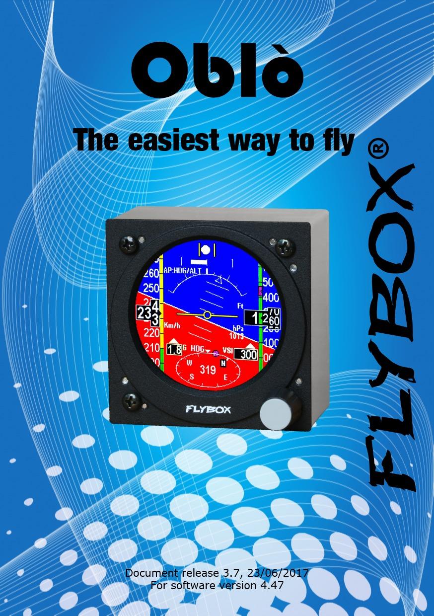
4 Introduction Flybox Thank you for purchasing a Flybox product. We hope it provides many years of service to you, becoming a useful instrument for easy and immediate consultation. Developing Oblò our intent was to create a compact and lightweight attitude indicator / EFIS, easy to install and to use. Oblò is equipped with state-of-the-art highly visible display and the latest generation of solid state inertial sensors to ensure reliability and accuracy over time. SYMBOLS USED IN THE MANUAL NOTE: Used to highlight important informations. CAUTION: Used to warn the user and indicate a potentially hazardous situation or improper use of the product. WARNING: Used to indicate a dangerous situation that can cause personal injury or death if the instruction is disregarded.
5 Flybox Important notices & warnings NOTE: Keep this manual in the aircraft. This document must accompany the instrument in the event of change of ownership. NOTE: This device is intended for installation onto non type certified aircraft only, because it has no aviation certifications. Refer to your local aviation authorities to check if this device may be installed in your aircraft. CAUTION: Read entirely this manual before installing the instrument in your aircraft, and follow the installation and operating instructions described here. CAUTION: The pilot must understand the operation of this instrument prior to flight, and must not allow anyone to use it without knowing the operation. Don't use this instrument in flight until you are sure of the correct operating of the same. CAUTION: This instrument cannot be used under any circumstances to conduct flights in IMC conditions. CAUTION: When the installation is finished you must do a test, prior to flight, switching on all the possible source of electric noise and checking the properly operation of this instrument. CAUTION: Using this instrument over the maximum allowable ranges can cause malfunction or wrong indications.
6 Important notices & warnings Flybox CAUTION: The software of this instrument can be subject to change, update, addition or removal of functions, so also the operating mode of the instrument can be subject to change. Always refer to the installation and operating manual updated with the software version used in your instrument. To obtain updated software and manuals, please visit WARNING: Responsibility for installation lies entirely with the installer. Responsibility for operations lies entirely with the operator. Responsibility for any calibration, alarms thresholds and activations, every customizable instruments thresholds or any other settings lies with the person performing these modifications. WARNING: Do not solely rely on the Oblò to determine the primary flight informations. Always compare the informations provided with other primary flight instruments to recognize eventual malfunction. IMPORTANT: If you do not agree with the notices above do not install the Oblò in your aircraft, but return the product for a refund. Microel s.r.l. reserves the right to change or improve its products. Information in this document is subject to changes without notice.
7 Index INDEX SECTION 1 - Standard Oblò installation Mechanical installation Electrical and pneumatic installation General wiring hints Optional accessories available Altitude serial out for transponder Primary actions after installation SECTION 2 - Oblò-A/P installation Mechanical installation Oblò-A/P installation ACU control unit installation Servo/s installation Electrical installation SECTION 3 - Oblò-REP (repeater) installation Oblò-REP (repeater) installation Electrical installation Oblò standard >Oblò-REP Electrical installation Oblò-A/P >Oblò-REP SECTION 4 - Instrument configuration Main menu configuration Zero pitch TRK/HDG Light G-meter reset Setup menu configuration T.R.I. (Turn rate indicator) Ball (Slip indicator) I
8 Index Flybox Roll Pitch ASI (Airspeed) ALT/VSI (Vertical scale indicator) Autopilot G-meter GPS HSI Compass ADI Config About FW Upgrade Magnetic calibration SECTION 5 - Using the Oblò Using the Oblò Attitude indicator page HSI page Drum altimeter page SECTION 6 - Autopilot system Autopilot system Requirements Autopilot overview Remote disengage button Autopilot system configuration Servo/s calibration Communications check Remote button operation check Servo torque check II
9 Index Autopilot setup menu Min Spd and Max Spd parameters setting Roll servo setup Pitch servo setup Remote button setup Flight based test and configuration Autopilot setup - Roll axis (Flight based) Autopilot setup - Pitch axis (Flight based) SECTION 7 - Autopilot operation Autopilot operation How to engage and disengage the autopilot Details of operation Autopilot related alarms Important notices - safety checks Autopilot activation procedure SECTION 8 - Use of the Oblò-REP (optional) Use of the Oblò-REP SECTION 9 - Technical specifications Technical specifications APPENDIX A - Altimeter calibration APPENDIX B - Detail of optional wirings APPENDIX C - Detail of optional GPS module WARRANTY Revision history III
10 Page intentionally left blank 10
11 INSTALLATION SECTION 11
12 Standard Oblò installation Mechanical installation Flybox SECTION MECHANICAL INSTALLATION 1) Oblò fits in a standard 3 1/8 (80 mm) cutouts. On the panel it's necessary to make the cutout for the knob on the lower right hole. 2) The installation location must be carefully chosen since Oblò contains magnetic sensors for the compass indication. Given that a location without magnetic interference can be difficult or impossible to find, it s recommended to install the instrument in the top row of the instrument panel, to limit the interference of cables, switches and breakers that are usually found at the bottom. Do not install near any magnetic sources (wires that carry large amount of current, magnets/electromagnets, electric motors, airplane parts or metal parts that may have residual magnetic field). As a general rule keep a minimum distance of 30cm, but 60cm or more are recommended. To test if the location where you intend to install it is appropriate, turn on all the electrical loads (in particular radio and strobe lights) and move a handheld compass around the area making sure that the compass needle is stable (should not cycles back and forth) and is approximately indicating the magnetic North. Small deviations from the North can be compensated with the magnetic calibration (see chap.4.3) 12
13 Standard Oblò installation Mechanical installation 3) During use the instrument become warm so it's necessary to have some air circulation inside the instruments room, to avoid that the temperature increase over the operating limits. 4) Avoid placing in hot locations (for example near heater vents). 5) Find a location where the display will always be completely visible. 13
14 Standard Oblò installation Mechanical installation Flybox Front view 14
15 Standard Oblò installation Mechanical installation Side view 15
16 Standard Oblò installation Mechanical installation Flybox Panel cut-out - All dimensions are in millimeters. 16
17 1.2 ELECTRICAL AND PNEUMATIC INSTALLATION Standard Oblò installation Electrical installation On the backpanel of the Oblò there is a 15 poles D-sub plug connector, supplied with the corresponding 15-pole receptacle, one static and one pitot port. Use 1/8 NPT male fittings to connect the static pressure (STATIC) and the dynamic pressure (PITOT). CAUTION: Don't blow air inside the fittings. 17
18 Standard Oblò installation Electrical installation Flybox PIN# CON1 connector pinout Description 1 +12V Main supply 2 GND Main supply CAN H signal for autopilot control unit connection 3 (see chap.2.2) CAN L signal for autopilot control unit connection 4 (see chap.2.2) Open-collector alarm-out (active low) max 400mA / 5 5W (see chap.2.2) 6 Transponder altitude serial out (see chap.1.3) 7 Autopilot remote button (see chap.2.2) 8 Not used 9 USB-VCC 10 USB-D+ 11 USB-D- 12 USB-GND 13 Low-level intercom audio out (see chap.2.2) 14 GPS input (connect to TX signal of an external GPS) 15 Not used 18
19 Standard Oblò installation Electrical installation NOTE: Connections of pin# to a USB connector is used for software upgrades and for datalogger function (in development). CAUTION: The connection of the external GPS is highly recommended to increase the accuracy of the attitude indicator. It is also required for the tracking indication and for the automatic correction of magnetic declination. If you connect a GPS that is not powered by the aircraft bus (for example battery-powered), connect together the ground of the GPS and of the Oblò. If no external GPS is available use the Flybox GPS cod
20 Standard Oblò installation Electrical installation Flybox GENERAL WIRING HINTS: - Take care to properly insulate any exposed wire to avoid short circuits. - Insert a 1-Ampere circuit breaker to the power lead (+12V). - Use aeronautic cable for the wiring. CAUTION: Voltage peaks on the supply line that exceeds the operating limits (20V) can damage the device. OPTIONAL ACCESSORIES AVAILABLE: - Ready to use wiring (ord. cod ). - GPS receiver module (ord. cod ). - USB flash drive, for eventual software upgrades. - Backup battery system (ord.cod ). NOTE: Visit our web page for updated prices and informations. 20
21 1.3 ALTITUDE SERIAL OUT FOR TRANSPONDER CONNECTION Standard Oblò installation Electrical installation If you use a transponder with serial input for receiving the altitude data, it can be connected to the Oblò by following this steps: - To enable the transponder output it's required to connect a 10Kohm resistor between pin#1 and pin#14 (whether or not it's connected the external GPS on pin#14). - Ensure there is a shared ground between the Oblò and the transponder. - Wire a serial transmit line, using shielded cable, from the Oblò (pin#6 of the connector) to the respective receive connection on the transponder. The serial out of the Oblò is RS232 type, refer to the transponder manual for its installation and configuration. 21
22 Standard Oblò installation Electrical installation Flybox Connection of altitude serial out for transponder: The Oblò does not require any configuration, the altitude data is transmitted once per second with the followig protocol: Baud Rate Message formatting Example 9600 bps Alt,space,five altitude digits, carriage return ALT [CR] The message contains the current pressure altitude, in feet, with a fixed reference to mB (29.92 inches mercury). The resolution is 10 ft. NOTE: If you use the ready-to-use wiring (ord. cod or ), the 10 Kohm resistor between pin#1 and pin#14 is already fitted inside the connector housing of the wiring. 22
23 1.4 PRIMARY ACTIONS AFTER INSTALLATION Standard Oblò installation Pre-flight check WARNING: Do not fly until you have performed at least the actions indicated below: 1) Airspeed bar thresholds setting: It's essential to set the airspeed thresholds (bar colors) according to the V-speeds of the aircraft on which you installed the instrument, as explained in chapter 4.2, section ASI. Flying without correctly set this thresholds may be very dangerous because the airspeed bar indicate the colors relative to the various V-speeds incorrectly. The default factory settings are all preset to zero. 2) Magnetic calibration: The magnetic calibration after the installation of your Oblò is an essential procedure that you must perform before you fly. Not only the heading, but also the attitude indicator depends on a correct magnetic calibration. Without it there is no data stored for the magnetic sensors and the attitude indicator, that use this data also, may not work correctly. The magnetic calibration it's a simple procedure that is explained in chapter
24 Standard Oblò installation Pre-flight check Flybox 3) Instruments panel pitch adjust: For the proper operation of the attitude indicator it's necessary to compensate the inclination of the instruments panel regards the longitudinal axis of the aircraft, as explained in chap.4.2, Pitch parameter. 24
25 Oblò-A/P installation Mechanical installation SECTION MECHANICAL INSTALLATION OBLÒ-A/P INSTALLATION - Mechanical installation of Oblò A/P is identical to the standard Oblò (see chap.1.1) with the addition of: - Mechanical installation of ACU autopilot control unit. - Mechanical installation of servo/s. ACU AUTOPILOT CONTROL UNIT INSTALLATION The ACU is available in two versions, for horizontal or vertical mounting. - Required panel cutout: 120 x 36.1 mm. - Outer dimensions: x 42.1 mm. - Screw the ACU to the instruments panel with two M3 screws. 25
26 Oblò-A/P installation Mechanical installation Flybox Horizontal installation (dimensions in millimeters) 26
27 Oblò-A/P installation Mechanical installation Vertical installation (dimensions in millimeters) 27
28 Oblò-A/P installation Mechanical installation Flybox SERVO/S INSTALLATION : The Flybox FX75 digital servos incorporates important safety features: It has a reliable disengaging system: situations like severe turbolence or something other kind of anomaly will not be a problem, because the pilot can take in any case the immediate control of the plane. When the autopilot isn't engaged, the internal gears are completely disconnected, then at difference as some servomotors the pilot will not feel no residual torque at the command stick, giving a confortable flight. In case of mechanical failure, the gear train is engineered to be reversible: the pilot can overtop the power of the brushless motor, it provides to the servomotor a further safety level. The output torque is electronically adjustable, and in case of forced action from the pilot on the command stick, the disengage will be without the breaking of a shear pin (unlike other servomotors on the market that use that mechanical safety system that after the break, needs a remediation action to work again). 28
29 Oblò-A/P installation Mechanical installation A software function disengage the autopilot if the pilot override the servo for more than 1 seconds. It's recommended to install also the remote disengage button, to have an immediate way to disengage the autopilot even in presence of strong turbulence. For installation instructions refer to the installation manual, which is included with each servo. WARNING: improper installation of servos can lead to loss of control of the aircraft, resulting in damage to the aircraft itself and injury or death of the occupants. BE SURE TO CAREFULLY FOLLOW THE INSTALLATION INSTRUCTIONS, AND CONSULT A QUALIFIED INSTALLER. 29
30 Oblò-A/P installation Electrical installation 2.2 ELECTRICAL INSTALLATION Flybox AUTOPILOT SYSTEM INSTALLATION: To install the autopilot system, in addition to perform the standard installation as described in chap.1.2, you must also perform the following wirings: - Oblò ==> ACU control unit - ACU control unit ==> servo/s The ACU control unit has two Molex minifit-jr connectors: - 1 four-pole connector (here called CON4P ). - 1 eight-pole connector (here called CON8P ). Included in the kit there are the corresponding socket connectors (Molex P/N: R for 4-poles connector and R for 8-poles connector) and the crimp terminals (Molex P/N: 5556-TL). Each servos is provided with a 10-poles Molex Microfit connector (Molex ) and the corresponding crimp terminals (Molex ). 30
31 Oblò-A/P installation Electrical installation The electrical installation consists of the following wirings: - 12 Volt power supply: the power supply input is in the ACU control unit and power also the connected servos. Use wire with adequate sizing to minimize voltage drop and avoid that the wire become warm (recommended size: AWG18). CAUTION: Power must be supplied through a breaker connected exclusively to the ACU control unit, easily accessible to the pilot and clearly identified as Autopilot. If you have one servo only use a 4 Ampere breaker, if you have two servos use a 7.5 Ampere breaker. 1) Wirings between ACU control unit and Oblò instrument: the ACU is connected to the Oblò with a two-wires CAN bus communication line. Use a two-pole twisted cable or a two-pole with shield cable (shield connected to ground in one point only). AWG24 wires should be enough. 31
32 Oblò-A/P installation Electrical installation Flybox 2) Wirings of the servos: each servo need to be connected to the ACU control unit with two wires for the power supply (use AWG18 wires) and need to be connected to the CAN bus communication line using a two-pole twisted cable or a two-pole with shield cable (shield connected to ground in one point only). AWG24 wires should be enough. CAUTION: Do not route this line in parallel with transmitting antennas or other sources of known RF interference. Do not route this line in parallel with microphone cables or audio cables to avoid audible noise in headphones. 3) Wiring of the remote disengage button (RECOMMENDED): connect it between ground and pin#7 of the Oblò connector. The type of the button must be NORMALLY OPEN (NO). CAUTION: - Care should be taken to avoid that the wiring is subjected to chafing or excessive flexing. - Avoid if possible junctions, that with excessive vibration may be subjected to fail or short-circuit. 32
 Pin# Descriprion 1 CAN bus communication line: CAN-H signal 2 +12V main supply 3 CAN bus communication line: CAN-L")

33 Oblò-A/P installation Electrical installation CONNECTIONS DETAIL FOR ACU CON4P CONNECTOR Socket view (from wire s insertion side) Pin# Descriprion 1 CAN bus communication line: CAN-H signal 2 +12V main supply 3 CAN bus communication line: CAN-L signal 4 GND main supply CONNECTIONS DETAIL FOR ACU CON8P CONNECTOR Socket view (from wire s insertion side) Pin# Descriprion 1 GND for Pitch Servo 2 Not used 3 GND for Roll Servo 4 Not used 5 +12V for Pitch Servo 6 Not used 7 +12V for Roll Servo 8 Not used 33

34 Oblò-A/P installation Electrical installation Flybox CONNECTIONS DETAIL FOR FX75 SERVO CONNECTOR Socket view (from wire s insertion side) Pin# Descriprion 1 +12V power supply 2 Not used 3 Not used 4 CAN bus communication line: CAN-L signal 5 CAN bus termination 6 GND power supply 7 Not used 8 Not used 9 CAN bus communication line: CAN-H signal 10 CAN bus termination 34
35 Electrical connections for autopilot system Oblò-A/P installation Electrical installation *NOTE: If you use the ready-to-use wiring (ord. cod ), the 120 ohm resistor between pin#3 and pin#4 is already fitted inside the connector housing of the wiring. 35
36 Oblò-A/P installation Electrical installation Flybox NOTE: The CAN bus termination (pin#5 connected with pin#10) must be done only on the last servo of the CAN bus line. If you install only one servo, the CAN line must be terminated on that servo. 36
37 Oblò-REP installation Mechanical installation SECTION OBLÒ-REP (REPEATER) INSTALLATION Dimensions & mechanical installation of Oblò-REP are the same of standard Oblò (see chap.1.1) Electrical installation is different and depends if the Oblò-REP is connected to a standard Oblò or if it is connected to a Oblò-A/P with autopilot control unit and servos. See next pages for the appropriate wiring diagrams. 37
38 Oblò-REP installation Electrical installation Flybox ELECTRICAL INSTALLATION OBLÒ-REP CONNECTED TO A STANDARD OBLÒ 38
39 3.1.2 ELECTRICAL INSTALLATION OBLÒ-REP CONNECTED TO A OBLÒ-A/P WITH AUTOPILOT NOTE: The Oblò-REP share the same CAN bus line of the autopilot system. It can be connected at any point of the CAN bus line but the length of the wiring that connects the Oblò-REP must be maximum 1 meter. 39
40 USE SECTION 40
41 SECTION 4 Instrument configuration Main menu configuration 4.1 MAIN MENU CONFIGURATION Before using your Oblò you need to configure it; read completely this chapter and follow step by step the sections to fully configure it according to your preferences. Navigation through the menu is very simple and quick and is performed with the knob: - Press the knob for 1 second to enter in the functions menu. The menu automatically disappears if you don't press or rotate the knob for 5 seconds. - Rotate the knob to navigate through the menu items. - Press the knob to enter in the selected item. - The first item on every menu ( Exit or Back ) is used to exit the current menu and go back to the previous. 41
. LIGHT: display brightness adjustment (1=min. brightness, 19=max. brightness). Default value=19. SETUP: enter in the setup menu.")
42 Instrument configuration Main menu configuration Flybox EXIT: exit the menu and returns to the main screen. TRK or HDG: switch between Heading/Tracking compass indications. (Tracking available only if an external GPS is connected). LIGHT: display brightness adjustment (1=min. brightness, 19=max. brightness). Default value=19. SETUP: enter in the setup menu. ZERO PITCH: use this function only in flight because it reset the pitch to the actual attitude. Use only when the aircraft is in leveled flight and at constant speed, never use it to reset the horizon during other flight attitude. G-METER RESET: Show/reset g-meter. Turning the knob to highlight this item will display the maximum and minimum peaks of vertical acceleration. Press the knob if you want to reset the two peaks. 42
 Click the knob to enter the turn rate indicator configuration.")
, an high value means that the")
43 4.2 SETUP MENU CONFIGURATION: Instrument configuration Setup menu configuration EXIT: exit the menu and returns to the main screen. T.R.I.: (Turn rate indicator) Click the knob to enter the turn rate indicator configuration. The available settings are: - Scale: set the full scale, in degrees/seconds. Default value=6 /s. - Filter: filter setting. A low value means that the readings will be more fast and unfiltered (but subject to fluctuations), an high value means that the readings will be more slow and stable. Default value=80. 43
44 Instrument configuration Setup menu configuration Flybox BALL: (Slip indicator) Click the knob to enter the slip indicator configuration. The available settings are: - Scale: set the full scale, in millig. Default value=300mg. - Filter: filter setting. A low value means that the readings will be more fast and unfiltered (but subject to fluctuations), an high value means that the readings will be more slow and stable. Default value=80. ROLL: Click the knob to enter the roll scale configuration. The available settings are: - Arc mode: Set the roll indicator mode: set to 1 to choose a stationary roll scale (while the arrow moves to stay perpendicular to the horizon). Set to 2 to choose to rotate the scale while the arrow stay fixed at the center. Default value=1. 44
45 Instrument configuration Setup menu configuration - Adjust: adjustment of the roll to compensate misalignments due to installation. On the ground, with wings of the plane perfectly leveled, rotate slowly the knob until the number at the bottom become zero, then press it to store this value. Turn off and on the instrument after storing a new inclination value. Default value=0 PITCH: Click the knob to enter the pitch axis configuration. The available setting is: - Adjust: adjustment of the pitch to compensate the inclination of the instruments panel regards the longitudinal axis of the aircraft. This function must be executed only once after installation, on the ground, in leveled attitude. Read the number printed on the bottom of the display and copy the same value on this parameter by clicking the knob and rotating it. For example if the number printed on the bottom is -3.6 rotate the knob to the left to set exactly If the number printed on the bottom is +1.2 rotate the knob to the right to set exactly Click the knob to store the value and turn off and on again the instrument. Default value=0. 45
46 Instrument configuration Setup menu configuration Flybox ASI: Click the knob to enter the airspeed indictor configuration. The available settings are: - Vne-Vno-Vfe-Vs-Vs0: Set the speed setpoint for the moving tape airspeed indicator. Default value=0 Km/h. NOTE: Before setting these thresholds you must choose the unit of measure (see next parameter). Vne Vno (Velocity Never Exceed) (Velocity Normal Operation), maximum structural cruising speed. Vfe (Velocity with Flaps Extended), maximum airspeed at which you may extend the flaps, or fly with them extended. Vs Vs0 (Velocity of Stall), power off stalling speed with the gear and flaps retracted. (Velocity Stall 0), power off stalling speed with gear and full flaps extended. If you prefer the clean transition from white to green zone set the same value on Vs and Vfe. 46
47 Instrument configuration Setup menu configuration - Unit: Set the unit of measure for the airspeed indicator in kilometers per hour (Km/h), miles per hour (Mph) or knots (Kts). Default value=km/h. - Filter: filter setting. A low value means that the readings will be more fast and unfiltered (but subject to fluctuations), an high value means that the readings will be more slow and stable. Default value=90. ALT/VSI: Click the knob to enter the altimeter and vertical speed indicator configuration. The available settings are: - Oxygen: Set the max altitude above which the altitude tape turns red to indicate the hazardous condition. Default value=12000 Ft. - Alt unit: Set the unit of measure for the altimeter in meters (Mt) or feets (Ft). Default value=ft. - Baro unit: Set the unit of measure for pressure reference in hectopascal (hpa) or inches of mercury (inhg). - Alt Filter: altimeter filter setting. A low value means that the readings will be more fast and unfiltered (but subject to fluctuations), an high value means that the readings will be more slow and stable. Default value=90. 47
48 Instrument configuration Setup menu configuration Flybox - Vsi Filter: vertical speed indicator filter setting. A low value means that the readings will be more fast and unfiltered (but subject to fluctuations), an high value means that the readings will be more slow and stable. Default value=95. AUTOPILOT:(Only for autopilot enabled Oblò) see 6.2 G-METER: Click the knob to enter the g-meter indicator configuration. The available settings are: - Filter: filter setting. A low value means that the readings will be more fast and unfiltered (but subject to fluctuations), an high value means that the readings will be more slow and stable. Default value=50. - Refresh: with this parameter you can choose the display update rate between 1 (1 display refresh per second) and 3 0 (30 display refresh per second). Default value=2. - Max: Show the maximum peak reached by the g-meter. - Min: Show the minimum peak reached by the g-meter. - Reset min/max: Click the knob after selecting this item to reset the maximum and minimum peaks of the g-meter. 48
49 Instrument configuration Setup menu configuration GPS: Click the knob to enter the external GPS configuration (if connected). The available settings are: - Baud: Set the baud rate of the external GPS. Default value=4800 bps. - Utc: To check if the GPS is properly connected and the baud rate is correct verify that this indication provides the UTC time. If it shows :-- it means that the GPS is not connected or setup correctly. - Satellites: To check if the reception is good (and therefore also to know if you have choosen a good location where to install the GPS) read the number of satellites indicated: the higher the number, the better the reception. For a good reception at least 4 satellites should be indicated. CAUTION: In case of communication problems between GPS and Oblò check the following settings on the external GPS: - Baud rate/communication speed: must be set to the same value as that set in the Oblò. - Data protocol: must be set to NMEA. - Enabled messages: must be enabled on the GPS the $GPRMC e $GPGGA messages (standard messages that every GPS should transmit). If you want to use the HSI page or if you have installed the autopilot system and you want to use the navigation to a waypoint function, it must be enabled also the $GPRMB message. 49
50 Instrument configuration Setup menu configuration Flybox HSI: Click the knob to enter the HSI (Horizontal Situation Indicator) configuration menu. The available settings are: - XTE win.: Set the window amplitude of the cross track error indicators (the XTE window is measured from the two external dots). Default=1.0 Km. COMPASS: Click the knob to enter the compass configuration. The available settings are: 50 XTE window - Unit: Set the unit of measure for the indications on the HSI page. Choose between kilometers (KM), Nautical miles (NM) or Miles (MI). Default=KM. - Auto H/T: YES/NO. Set to YES to enable tha automatic switch between heading and tracking. In this mode if the actual speed is below the speed set in the next parameter the compass is set to heading; when the actual speed is higher the compass is set to GPS tracking. This feature is useful to automatically switch from magnetic heading when you are in ground to GPS tracking, with wind correction, when you are in flight. Default value=yes. - Speed: Set the speed for the automatic switch between heading and tracking (see previous item). Default value=60 Km/h. - Calibration: Magnetic calibration. See next chapter. - Mag.Dec.: Displays the magnetic declination of the actual place (the indication appear only with the GPS connected).

51 Instrument configuration Setup menu configuration ADI: Click the knob to enter the attitude director indicator setup. The available settings are: - Mode: 1 / 2 / 3. There are three different display mode of the indicator: MODE 1 MODE 2 MODE 3 CONFIG: Click the knob to enter the configurations menu. The available configurations are: - Start page: Set the start page (on instrument turn-on). Choose between the attitude indicator page (HOR), the HSI page (HSI) or the drum altimeter page (ALT). Default=HOR. - Return delay: Set the auto return to the start page after the time, in seconds, set here. Set to zero to disable the auto return. Default=0. - Knob: Set the operating mode of the knob. Rotate the knob to select the submenu called Menu DN and click to enter. The available settings are: - CCW: select this mode to set that by turning the knob counter-clockwise you move down in the menus. - CW: select this mode to set that by turning the knob clockwise you move down in the menus. 51

52 Instrument configuration Setup menu configuration Flybox ABOUT: On this screen it s possible to read current software versions, useful to check if your Oblò is updated to the latest version. The version number to check is in the first row, indicated after the word CORE. Check frequently our web site to see if there are any software updates. NOTE: this manual is referred to the software version indicated on the first page. FW UPGRADE: Menu for USB software upgrade. If you want to upgrade to a newer version, (see previous item to check the actual software version) after selecting this item keep pressed the knob for 2 seconds until the following screen appears: 52 - Insert the USB flash drive on which you copied the updated software and select if you want to upgrade the Oblò (by selecting CORE ) or if you want to upgrade the roll or pitch servo (by selecting RSU or PSU ). To upgrade all select Upgrade All. If you have the Oblò standard without autopilot, you can only upgrade the instrument itself by selecting the CORE item.
53 Instrument configuration 4.3 MAGNETIC CALIBRATION Oblò integrates the magnetic sensors for the heading indication. The sensors are affected by all magnetic fields present around them, which, if ignored, can lead to considerable errors in the heading indication. Magnetic fields are generated for example by ferro magnetic materials (iron, ferrites), large electric current in cables, electric motors; if possible it's recommended to avoid installation of the instrument near these source of magnetic fields.it's possible to compensate for weak static magnetic fields by performing the calibration as explained below. Please note that in particular cases (presence of strong magnetic fields) may be insufficient to perform this calibration; in this case the heading provide incorrect or approximate indications and it's necessary to install an external remote magnetometer (in development). CAUTION: Before using Oblò in flight it's necessary to perform the magnetic calibration to obtain a correct indication of the heading. 53
54 Instrument configuration Magnetic calibration Flybox The calibration must be performed after the installation is complete, by following this steps: 1) 2) 3) Turn on the engine and go in a place far from possible magnetic fields (metallic shed, concrete floors with metal armatures, etc..) and where is possible to execute more turn with the aircraft (on the ground). Turn on all the electric load usually used in flight. On the Oblò enter in the Setup-->Compass and select the Calibration item. Keep pressed the knob for 3 seconds to enter in the calibration. 4) 5) Now the display show PUSH TO START CALIBRATION : briefly press the knob to start calibration (if you want to cancel and return to the previous menu keep pressed the knob for 3 seconds). Wait the indication MAKE A 420 DEGREE CLOCKWISE CIRCLE SLOWLY on the display then start, with the aircraft on ground, a continuous slow circular movement toward right. 54
55 Instrument configuration Magnetic calibration 6) In the center of the display appear a number that indicate the rotation degrees, that starting from zero increase during the rotation of the aircraft. Continue the slow circular movement: the calibration end automatically when the number reach a value of 420 and the indication CALIBRATION DONE PUSH TO EXIT appear on the display. Now you can press the knob to terminate the calibration. 7) IMPORTANT: To complete the 420 degrees turn required for the calibration you must take from 1 to 2 minutes. After completing the calibration perform this check: with the Oblò displaying the heading turn the aircraft exactly at North, South, West and East verifying the correct indication on display. If external GPS is connected you will automatically obtain the magnetic declination correction. 55
56 Using the Oblò Flybox SECTION USING THE OBLO The Oblò is organized in 3 different pages: Attitude indicator page HSI (Horizontal Situation Indicator) page Drum altimeter page By default, after power-on the Oblò shows the attitude indicator page, but you can set your preferred start page by going in the Setup menu Config Start page. To switch between the pages you need to fast rotate the knob: fast rotate the knob clockwise to switch from attitude indicator page to HSI page and from HSI page to drum altimeter page; fast rotate the knob counterclockwise to go back in reverse order. The fast rotate of the knob is thought to avoid involuntary page change. You can also set a time to automatically return to the start page after you have switched to another page (See Setup menu Config Return delay). 56

57 5.1.1 ATTITUDE INDICATOR PAGE: SLIP INDICATOR TURN RATE ATTITUDE INDICATOR AIRSPEED ALTIMETER PRESSURE REFERENCE G-METER COMPASS VERTICAL SPEED INDICATOR COMPASS: Placed in the lower part of the screen, the heading/tracking indication is represented with the numerical indication at the center of the graphics. The four cardinal points are shown as N, S, W, E. - It can show the HEADING (magnetic compass, indicated with HDG ) or the TRACKING (Track of the GPS, indicated with TRK, available only if an external GPS is connected). - Note that after power-on the compass is set to heading and can automatically switch to tracking above a certain speed if you enable the Auto H/T function in the compass setup menu (see chap.4.2). - It's however possible to manually switch between the two indications: keep pressed the knob for 1 second and in the menu that appear choose HDG or TRK. 57
58 Using the Oblò Attitude indicator page Flybox The HEADING is valid either stationary or moving and during aircraft turns the indicator is fluid and continuous. It compensate for aircraft attitude so that the indication is valid also with pitch or roll inclination. If external GPS is connected you will automatically obtain the magnetic declination correction. The TRACKING is read from external GPS receiver and is usually updated once per second, so in case of fast turns it may not have a continuous and fluid indication. Provided that GPS receiver have a good satellites reception, the tracking indication is very accurate and compensated from wind. NOTE: The GPS tracking is not valid when stationary or for speed below 20 km/h. 58
59 Using the Oblò Attitude indicator page TURN RATE: Graphical indications of the turn rate. To set the full scale go in the Setup menu-->t.r.i.-->scale (see chap.4.2). AIR SPEED: The Air speed is represented with both tape and numeric indicator. The unit of measure can be km/h, Mp/h or knots. The range of measure is from 30 to 650 km/h (16~350 knots or 18~403 mph). Below air speed of 30 km/h the indication remain fixed to zero. To set the unit of measure and the speed thresold that define the coloured zone go in the Setup menu-->asi (see chap.4.2). ATTITUDE INDICATOR: With 360 continuous operation in both pitch and roll. Above and below the horizon line, major pitch marks are shown for every 10, up to +/- 40. Minor pitch marks are shown for every 5. The roll scale show inclinations from -60 to +60 ; mark lines are shown for the following inclination:

60 Using the Oblò Attitude indicator page Flybox Roll scale zero Horizon zero The colors used for the attitude indicator are brown for the ground and sky blue for the sky. The zero is represented by the yellow line. 60
61 Using the Oblò Attitude indicator page IMPORTANT NOTES ON USING ATTITUDE INDICATOR: The attitude indicator may loose accuracy during the flight for the following causes: - During uncoordinated, accentuated or acrobatics maneuvers. - Rapid temperature changes or temperature outside the operating limit (-20 C~+70 C). Never use the attitude indicator as a reference for flight manoeuvres. Never use the attitude indicator as a reference in absence of visibility. NOTE: This instrument is not certified. 61
62 Using the Oblò Attitude indicator page Flybox SLIP INDICATOR: It's a graphic indication of the lateral accelerations. ALTIMETER: It include both a tape indicator and a numeric indicator. The unit of measure can be feets or meters, the range of measure is -1000~25000 feets (-300~ m). On the tape indicator the thousands digits are shown every 500 (i.e. 1500,2000, etc..) while the numeric indications is always displayed completely. - To change the PRESSURE REFERENCE click the knob and then rotate it to change the numerical value; click again to store the new reference. VERTICAL SPEED INDICATOR: Displays the numerical indication (absolute value). The unit of measure is meters per second if altimeter is set in meters or feet per minute if the altimeter is set in feet. The arrow pointing up indicate an ascent (positive value), the arrow pointing down indicate a descent (negative value). G-METER: Indicate the vertical acceleration in g; it display also an upward arrow during positive accelerations or a downward arrow during negative accelerations. 62 The g-meter has a memory for storing the maximum and minimum acceleration peaks: to see them entern in the function menu by pressing the knob for 1 second and then select the item G-meter reset.
63 Using the Oblò Attitude indicator page CAUTION: If the instrument's internal temperature exceeds the maximum allowed (70 C) it appears to display the message SENSOR TEMPERATURE OUT OF HIGH LIMIT. High temperatures can be reached for example if the aircraft is parked in the sun without any instruments panel protection. In this case to decrease the temperature it's sufficient to ventilate the instruments panel. If the temperature exceeds the minimum allowed (-20 C) it appears to display the message SENSOR TEMPERATURE OUT OF LOW LIMIT. In both cases the data provided by the instrument may be not reliable. It's possible to check the instrument's internal temperature on the About menu ( Int. Temp item). 63
 page reduces pilot workload by providing heading/tracking, course reference, course deviation and other navigation aid.")
 or the TRACKING (Track of the GPS, indicated with TRK ).")
64 5.1.2 HSI PAGE: ACTUAL HEADING OR TRACKING COMPASS BUG COURSE POINTER DESTINATION WAYPOINT ID GROUND SPEED COURSE DEVIATION INDICATOR DISTANCE TO GO TIME TO GO COURSE CROSS TRACK ERROR The HSI (Horizontal Situation Indicator) page reduces pilot workload by providing heading/tracking, course reference, course deviation and other navigation aid. In order to work, the HSI page needs that the Oblò is connected to an external GPS navigation system, in which a flight plane, route or GOTO has been set. The available indications are the followings: 64 ACTUAL HEADING OR TRACKING: It can shows the HEADING (magnetic compass, indicated with HDG ) or the TRACKING (Track of the GPS, indicated with TRK ). Note that after power-on the compass is set to heading and can automatically switch to tracking above a certain speed if you enable the Auto H/T function in the compass setup menu (see chap.4.2).
65 Using the Oblò HSI page During the flight is possible to manually switch between the heading or the tracking: keep pressed the knob for 1 second and in the menu that appear choose HDG or TRK. COMPASS BUG: The compass bug can be freely moved by the pilot by clicking the knob and rotating to select a new heading/tracking. If it s installed the optional autopilot system and you start a navigation on it, the bug will be coupled to the autopilot. COURSE POINTER: This pointer indicates the currently selected course (it is automatically programmed by the GPS route). COURSE DEVIATION INDICATOR: The CDI indicates how far to the left or right you are from the selected course. A series of "dots" provides a linear indication of how far the aircraft is "off course". To set the full scale of the dots, go in the setup menu HSI XTE win parameter. DESTINATION WAYPOINT ID: It shows the name of the destination waypoint, if transmitted by the GPS navigator. If no information is received this field is left blank. DISTANCE TO GO: It shows the distance from your aircraft s position to the next waypoint (in kilometers (KM), Nautical miles (NM) or Miles (MI), depending on what you have set on the HSI setup menu). TIME TO GO: It shows the time needed to reach the next waypoint. GROUND SPEED: It shows the ground speed (this data is received from the GPS). COURSE: It shows the course to mantain to reach the waypoint. 65
. 5.1.3 DRUM ALTIMETER PAGE: PRESSURE REFERENCE (hpa) PRESSURE REFERENCE (InHg) This page simulates the graphic of a traditional drum altimeter.")
66 CROSS TRACK ERROR: It shows the numerical indication of the deviation from the selected course (in kilometers (KM), Nautical miles (NM) or Miles (MI), depending on what you have set on the HSI setup menu) DRUM ALTIMETER PAGE: PRESSURE REFERENCE (hpa) PRESSURE REFERENCE (InHg) This page simulates the graphic of a traditional drum altimeter. To change the PRESSURE REFERENCE click the knob and then rotate it to change the numerical value; click again to store the new reference. The settable pressure reference is the one corresponding to the unit of measure setted on the Setup menu ALT/VSI Baro unit. 66
67 Autopilot system SECTION AUTOPILOT SYSTEM REQUIREMENTS: The following components are required for the autopilot to function: - Flybox Oblò-A/P instrument or Oblò with autopilot function enabled (see chap.7.6). NOTE: Upgrade your Oblò to the latest version before using the autopilot function (check web site - Autopilot Control Unit (Flybox ACU). - 1 Flybox FX75 digital servo for roll control. - 1 Flybox FX75 digital servo for pitch control. 67
68 Autopilot system Autopilot overview Flybox AUTOPILOT OVERVIEW: The autopilot system can use 1 or 2 servos, that need to be connected to the control stick for roll and pitch control. The available functions are: Horizontal navigation (roll axis control): - Magnetic heading hold. - GPS tracking hold. - Track to a waypoint (GOTO function, require an external GPS with NMEA messages $GPRMC $GPRMB $GPGGA). - Track a flight plane (require an external GPS with NMEA messages $GPRMC $GPRMB $GPGGA). Automatic course reversal (180 ). Vertical navigation (pitch axis control): - Altitude hold. - Altitude change. 68
 NAV button with led (led on when autopilot is engaged in NAV mode) ALT button with led (led on when autopilot is engaged in ALT mode) - Use the ON/OFF switch to turn on and off the")
69 Autopilot system Autopilot overview ON/OFF switch HDG/TRK knob for heading/tracking setting ALT knob for altitude setting ON led indicator HDG/TRK button with led (led on when autopilot is engaged in HDG/TRK mode) NAV button with led (led on when autopilot is engaged in NAV mode) ALT button with led (led on when autopilot is engaged in ALT mode) - Use the ON/OFF switch to turn on and off the autopilot control unit. - Press the HDG/TRK button to engage/disengage the autopilot in heading or GPS tracking mode. - Rotate the HDG/TRK knob to adjust the heading/tracking bug. Press the knob to center the bug to the actual heading or GPS tracking. - Press the ALT button to engage/disengage the autopilot in altitude hold mode. - Rotate the ALT knob to adjust the altimeter bug. Press the knob to center the bug to the actual altitude. - Press the NAV button to engage/disengage the autopilot in flight plane or goto navigation. 69
70 Autopilot system Autopilot overview Flybox REMOTE DISENGAGE BUTTON: It's recommended to install also the remote disengage button, that operate in this way: - With autopilot engaged: push shortly to disengage. - With autopilot disengaged: push for 2 seconds to engage it. This function must be enabled from menu: Setup Autopilot Remote button HtoE enable (see chap.6.3.4). - With autopilot engaged: keep pressed for more than 2 seconds to activate the Control Wheel Steering (CWS) mode: it's possible to fly the aircraft to a new heading/traking or altitude and then release the button to let the autopilot acquire and mantain the new values. This function must be enabled from menu: Setup Autopilot Remote button CWS enable (see chap.6.3.4). 70
71 Autopilot configuration 6.2 AUTOPILOT SYSTEM CONFIGURATION After the physical installation of the autopilot system it's required to check the connections and configure the parameters, as explained in the following two chapters. The operations that you will perform in sequence are the following: Ground based test and configuration: - Servos calibration (chap.6.2.1) - Communications check (chap.6.2.2) - Remote button operation check (chap.6.2.3) - Servos torque check (chap.6.2.4) - Min speed and Max speed parameters setting (chap.6.3.1) - Roll servo setup (chap.6.3.2) - Pitch servo setup (chap.6.3.3) - Remote button setup (chap.6.3.4) Flight based test and configuration: - Autopilot setup roll axis (chap.6.4.1) - Autopilot setup pitch axis (chap.6.4.2) 71

72 Autopilot configuration Flybox SERVO/S CALIBRATION The servo/s calibrations is GROUND BASED. The calibration procedure is mandatory: if you try to engage the autopilot without first calibrate the servo, the Oblò will show the error message AUTOPILOT DISENGAGE! ROLL/PITCH SERVO CALIB. THE CALIBRATION MUST ALSO BE REPEATED IN THE EVENT OF ANY CHANGES TO MECHANICAL INSTALLATION OF THE SERVO/S. NOTE: The neutral position terms used in the following explanation means the center of the servo arm travel relative to the position of the limiting bracket: 72
73 Autopilot configuration Servo/s calibration To begin the calibration procedure: - Press for 1 second the knob to enter in the function menu. - Rotate the knob to select the Setup menu and click to enter. - Rotate the knob to select the Autopilot menu and click to enter. - Rotate the knob to select the Servo(s) calib. - Press the knob for 3 seconds until the display shows the word IDENTIFICATION. If instead it was already made a previous calibration, the display shows the data of the previous calibration as in example below: NOTE: If appears the message NO SERVO(S) FOUND it means that the servos are not properly connected. 73
74 Autopilot configuration Servo/s calibration Flybox - Press the knob to start the calibration and follow the onscreen instructions; for example if you have installed the servos on both roll and pitch axis the complete procedure will be as follows: Step#1: center the control stick in neutral position and then click the knob to go to the next step. Step#2: position the control stick to the left limit (without forcing), paying attention to not move it in the pitch axis during the motion. After doing so, the calibration automatically switch to the next step: Step#3: center the control stick in neutral position and then click the knob to go to the next step. Step#4: position the control stick to the forward limit (without forcing), paying attention to not move it in the roll axis during the motion. After doing so, the calibration automatically switch to the next step or, if you have not installed the pitch servo, click the knob to go to the next step. Step#5: center the control stick in neutral position and then click the knob to go to the next step. 74
75 Autopilot configuration Servo/s calibration Step#6: position the control stick to the left limit (without forcing). Click the knob or the remote button to store the position and go to the next step. Step#7: position the control stick to the right limit (without forcing). Click the knob or the remote button to store the position and go to the next step. NOTE: If appears the message BAD MECHANICAL INSTALLATION! NOT ENOUGH SERVO TRAVEL it means that the servo is not correctly installed, as the travel of the servo arm is too small to function properly. In this case you should modify the mechanical installation, for example by using an outer hole of the servo arm. Step#8: position the control stick to the forward limit (without forcing). Click the knob or the remote button to store the position and go to the next step. Step#9: position the control stick to the backward limit (without forcing). Click the knob or the remote button to store the position and end the calibration. 75
76 Autopilot configuration Servo/s calibration Flybox NOTE: If appears the message BAD MECHANICAL INSTALLATION! NOT ENOUGH SERVO TRAVEL it means that the servo is not correctly installed, as the travel of the servo arm is too small to function properly. In this case you should modify the mechanical installation, for example by using an outer hole of the servo arm. At the end of the calibration procedure the display briefly shows the confirmation message Servo Calib Done. To exit the calibration menu keep pressed the knob for 3 seconds. 76
77 Autopilot configuration Servo/s calibration SERVO/S CALIBRATION CHECK WARNING: Once finished the calibration you must execute this check (ground based): - With the Oblò and ACU control unit turned on, insert the autopilot on roll axis by pressing the H D G / T R K button on the ACU. Rotate clockwise the HDG/TRK knob (so that the heading bug is at the right of the actual heading) and check that the flight control move as to turn the aircraft right. Rotate counter clockwise the HDG/TRK knob (so that the heading bug is at the left of the actual heading) and check that the flight control move as to turn the aircraft left. Check also that the servo pitch does not move. - Engage the autopilot on pitch axis by pressing the ALT button on the ACU. Using the ALT knob set the altitude bug to a higher value than the actual altitude and check that the flight control move as to increase the aircraft altitude; set the altitude bug to a lower value than the actual altitude and check that the flight control move as to decrease the aircraft altitude. If movement direction of one or both servos is reversed it means that the calibration is wrong, so NEVER ENGAGE THE AUTOPILOT IN FLIGHT but repeat the servos calibration procedure and check again. 77

78 Autopilot configuration Flybox COMMUNICATIONS CHECK This check must be performed GROUND BASED. - Turn on Oblò instrument only. - Turn on ACU control unit and check that appear AP:OFF in the top left corner of the display. If no message appear means that there is a communication problem between Oblò and ACU control unit: check again the electrical wirings. - Press the HDG/TRK button on the ACU panel and verify that the message AP:OFF become AP:HDG. If the message remains AP:OFF it means that there is a communication problem between ACU control unit and servo/s: check again the electrical wirings. 78
79 Autopilot configuration REMOTE BUTTON OPERATION CHECK This check must be performed GROUND BASED. - Engage the autopilot by pressing the HDG/TRK button on the ACU (check the message AP:HDG on the Oblò display). - Press the remote disengage button and check that the message AP:HDG become AP:OFF. If the message remains AP:HDG it means that there is a problem with the remote button: check the electrical wiring and the correct functionality of the button itself. 79
80 Autopilot configuration Flybox SERVO TORQUE CHECK This check must be performed GROUND BASED. - Engage the autopilot by pressing the HDG/TRK button on the ACU (check the message AP:HDG on the Oblò display). - Force the control stick to the left or right limit, so that you override the servo force and after 1 seconds the autopilot disengages automatically (check the message AP:OFF on display). - Engage the autopilot by pressing the ALT button on the ACU (check the message AP:ALT on the Oblò display). - Force the control stick to the forward or backward limit, so that you override the servo force and after 1 seconds the autopilot disengages automatically (check the message AP:OFF on display). At this stage you should check also the override force: it must be strong enough to give a fairly good control authority to the servos, but not so strong as to be difficult to override with the control stick. See chap for roll servo torque setup and chap for pitch servo torque setup. 80
81 Autopilot configuration 6.3 AUTOPILOT SETUP MENU The parameters configuration is performed on the Oblò instrument. During the configuration it's required to turn on also the ACU control unit but without engaging the autopilot (so on the ACU control unit turn on the ON/OFF switch and don't press any other button). All the configurable parameters are on the Oblò menu, accessible in this way: - Press for 1 second the knob to enter in the function menu. - Rotate the knob to select the Setup menu and click to enter. - Rotate the knob to select the Autopilot menu and click to enter. 81
82 Autopilot configuration Autopilot setup menù MINSPD AND MAXSPD PARAMETERS SETTING Flybox This settings must be performed GROUND BASED. The autopilot system measures the airspeed and allows the pilot to set the minimum and maximum operating speed to ensure that the aircraft is in safe conditions when the autopilot is engaged. MIN SPD: Select the minimum airspeed at which the autopilot will fly the aircraft. The unit of measure is the same set for the ASI (see Setup menu ASI Unit). The autopilot cannot be engaged at airspeed below Min Spd, with the exception of 0 to allow ground testing. With autopilot engaged, if the airspeed drops below the minimum, it enters to an airspeed hold mode, to restore and maintain approximately the minimum airspeed. Set Min Spd to be at least 20% above the Vfe of your aircraft. The Vfe speed must be set in the Oblò according to the specifications of your aircraft (to set the Vfe, see Setup menu ASI Vfe). 82
83 Autopilot configuration Autopilot setup menù MAX SPD: Select the maximum airspeed at which the autopilot will fly the aircraft. The unit of measure is the same set for the ASI (see Setup menu ASI Unit). With autopilot engaged, if the airspeed rises above the maximum, it enters to an airspeed hold mode, to restore and maintain approximately the maximum airspeed. The choice of the Max Spd value must be made according to the characteristics of your aircraft, it should be below the Vne speed of your aircraft but above the normal cruise speed. The Vne speed must be set in the Oblò according to the specifications of your aircraft (to set the Vfe, see Setup menu ASI Vne). Max Spd parameter cannot be set to a value above 95% of Vne, so you should first check the correctness of the ASI speed settings. 83

84 Autopilot configuration Autopilot setup menù ROLL SERVO SETUP Flybox This settings must be performed GROUND BASED. This settings can be performed inside the ROLL SERVO menu, that can be reached in this way: - Press for 1 second the knob to enter in the function menu. - Rotate the knob to select the Setup menu and click to enter. - Rotate the knob to select the Autopilot menu and click to enter. - Rotate the knob to select the Roll servo menu and click to enter. 84
85 GAIN PARAMETER CHECK This check must be performed GROUND BASED. GAIN: This parameter specify how fast or slow the autopilot responds to deviations between commanded and actual heading/tracking. For now check only that the parameter is at the default value (10), because it will be set in flight as explained later in chap The min-max range is: 1~40. TORQUE PARAMETER SETTING Autopilot configuration Autopilot setup menù This settings must be performed GROUND BASED. TORQUE: Set the desired torque, that is the force of the servo when engaged. To set a correct value, keep in mind that the torque must be strong enough to give a fairly good control authority to the servos, but not so strong as to be difficult to override with the control stick. To test the torque after setting a new value, perform the Servo torque check as explained in chap The min-max range is: 1~40, when the autopilot system detects for the first time that the servo is set as a roll servo, it set the default value to
86 Autopilot configuration Autopilot setup menù TURN RATE PARAMETER SETTING Flybox This settings must be performed GROUND BASED. TURN RATE: Select your desired target rate of turn when autopilot is engaged. The unit of measure is degrees per second and the range min-max is from 0.5 /s to 3.0 /s. When selecting your desired turn rate consider that the autopilot may slightly exceed the turn rate target during regulation. MAX BANK PARAMETER SETTING This settings must be performed GROUND BASED. MAX BANK: This parameter specifies a maximum bank angle which the autopilot will not exceed during turns. Set an appropriate bank limit, the min-max range is: 5~30 degrees. 86

87 6.3.3 PITCH SERVO SETUP Autopilot configuration Autopilot setup menù This settings must be performed GROUND BASED. This settings can be performed inside the PITCH SERVO menu, that can be reached in this way: - Press for 1 second the knob to enter in the function menu. - Rotate the knob to select the Setup menu and click to enter. - Rotate the knob to select the Autopilot menu and click to enter. - Rotate the knob to select the Pitch servo menu and click to enter. 87
88 Autopilot configuration Autopilot setup menù Flybox GAIN PARAMETER CHECK This check must be performed GROUND BASED. GAIN: This parameter specify how fast or slow the autopilot responds to deviations between commanded and actual altitude. For the moment check only that the parameter is at the default value (13), because it will be set in flight as explained later. The min-max range is: 1~40. TORQUE PARAMETER SETTING This settings must be performed GROUND BASED. TORQUE: Set the desired torque, that is the force of the servo when engaged. To set a correct value, keep in mind that the torque must be strong enough to give a fairly good control authority to the servos, but not so strong as to be difficult to override with the control stick. To test the torque after setting a new value, perform the Servo torque check as explained in chap The min-max range is: 1~40, when the autopilot system detects for the first time that the servo is set as a pitch servo, it set the default value to
89 Autopilot configuration Autopilot setup menù CLIMB PARAMETER SETTING This setting must be performed GROUND BASED. CLIMB: This parameter sets the average vertical speed for autopilot-commanded climbs.the unit of measure is meters/second or feet/minute, depending on what you have choosen for the altimeter. The range min-max is: 50~2000 feet/minute (0.1~10 meters/second). When selecting your desired climb rate consider that the autopilot may slightly exceed from target value during regulation. (Default value = 500). DESCENT PARAMETER SETTING This setting must be performed GROUND BASED. DESCENT: This parameter sets the average vertical speed for autopilot-commanded descents.the unit of measure is meters/second or feet/minute, depending on what you have choosen for the altimeter. The range min-max is: 50~2000 feet/minute (0.1~10 meters/second). When selecting your desired descent rate consider that the autopilot may slightly exceed from target value during regulation. (Default value = 300) 89
90 Autopilot configuration Autopilot setup menù Flybox MAX PITCH PARAMETER SETTING This setting must be performed GROUND BASED. MAX PITCH: This parameter specifies a maximum pitch angle which the autopilot will not exceed during climbs or descents. Set an appropriate bank limit, the min-max range is: 5~20 degrees (Default value = 10). 90

91 6.3.4 REMOTE BUTTON SETUP Autopilot configuration Autopilot setup menù The 'Remote Button' setup menu can be reached in this way: - Press for 1 second the knob to enter in the function menu. - Rotate the knob to select the Setup menu and click to enter. - Rotate the knob to select the Autopilot menu and click to enter. - Rotate the knob to select the Remote button menu and click to enter. The settings must be performed GROUND BASED. 91
92 Autopilot configuration Autopilot setup menù HtoE enable (Hold to engage enable): Flybox Enable (YES) or disable (NO) the function to engage the autopilot when the button is pressed for 2 seconds. The default value is NO so the remote button will only serve to disengage the autopilot when already engaged. HtoE mode (Hold to engage mode): Select the autopilot engage mode using the remote button (if enabled, see previous parameter). Set to HDG to engage the autopilot in horizontal navigation (roll), set to ALT to engage the autopilot in vertical navigation (pitch), set to HDG/ALT to engage the autopilot in both axes. CWS enable (Control wheel steering enable): Enable (YES) or disable (NO) the following auxiliary function of the remote button: during autopilot control, press and hold for more than 2 seconds the button (on the display will be displayed AP:CWS ) and fly to a new heading and/or altitude, then release the button to reengage the autopilot. By default this function is disabled. 92
93 Autopilot configuration 6.4 FLIGHT BASED TEST AND CONFIGURATION During this phase you calibrate the servo response to match your aircraft flight dynamics. Although flight testing may be carried out in different ways, it's recommended to follow the procedures indicated in the following chapters. CAUTION: Any test and configuration during flight must be executed in VFR conditions, with good weather and visibility conditions, at an adequate altitude and no traffic or obstacles in the flight path. It's also recommended to have another pilot on board during first flight configuration. NOTE: In case you need to instantly disengage the autopilot you can use either one of this way: - Turn off the ON/OFF switch on the ACU control unit. - Push shortly the remote button. - Press the HDG/TRK button on the ACU, if autopilot is in heading/tracking mode, or press the NAV button if autopilot is in navigation mode. Remember these actions so that it can be carried out instinctively in case of difficulties or emergencies. 93
94 Autopilot configuration Flight based test and configuration Flybox Before starting the first test flight verify once more for safety that all the parameters are correctly set: - Press for 1 second the knob to enter in the function menu. - Rotate the knob to select the Setup menu and click to enter. - Rotate the knob to select the Autopilot menu and click to enter. - Rotate the knob to select the Roll servo menu and click to enter. - Verify that the Gain parameter is set to default value, that is Verify that the Torque, Turn rate and Max Bank parameters are set according to your preferences, as explained in chapter Rotate the knob to select the Back item and press it to go back to the autopilot menu. - Rotate the knob to select the Pitch servo menu and click to enter. - Verify that the Gain parameter is set to default value, that is Verify that the Torque, Climb, Descent and Max pitch parameters are set according to your preferences, as explained in chapter
95 Autopilot configuration Flight based test and configuration AUTOPILOT SETUP ROLL AXIS (FLIGHT BASED) AUTOPILOT ENGAGE AND GAIN PARAMETER SET - Start the flight and when you are in safe condition (read chap.6.4) insert the autopilot by pressing the HDG/TRK button on the ACU control unit (the led will turn on as confirmation). Note that the autopilot will only hold the current heading by controlling the roll axis, so the pitch axis must be controlled by the pilot; ensure that you are not affecting the roll axis, so that you can determine the autopilot performance. If the autopilot behavior is sufficiently stable keep it engaged for some minutes and observe the way in which it mantains the heading/tracking: - If the autopilot deviates heavily from the heading/tracking set, or make very slow adjustments, you need to increase the value of the Gain parameter. - If the autopilot is too aggressive with excessively fast adjustments, you need to decrease the value of the Gain parameter. 95
96 Autopilot configuration Flight based test and configuration Flybox The Gain parameter selects the amount of autopilot activity for a given roll angle error (that is the difference between the desired heading/tracking and the actual heading/tracking). With low Gain values (minimum=1) the autopilot system is very slow with few corrections, with high Gain values (maximum=40) the autopilot is more aggressive with a lot of fast corrections. Above a certain upper limit, however, the system becomes unstable and start to oscillate. To change the Gain parameter: - Press for 1 second the knob to enter in the function menu. - Rotate the knob to select the Setup menu and click to enter. - Rotate the knob to select the Autopilot menu and click to enter. - Rotate the knob to select the Roll servo menu and click to enter. - Rotate the knob to select the Gain parameter and click to enter. - Rotate the knob to change the value and press it to store the new value. As you can imagine the optimal setting is highly dependent on the flight controls and the aircraft type, so you probably find the optimal setting after some flights, in which you learn also the way the autopilot control the aircraft. 96
97 HEADING/TRACKING CHANGE During this phase you observe the autopilot behavior during a turn, further optimizing the Gain parameter which as said is what establishes the autopilot response. - Repeat again some heading/tracking change, observing the behavior of the autopilot: Autopilot configuration Flight based test and configuration - With the autopilot engaged in HDG/TRK mode, start an autopilot commanded turn by rotating the HDG/TRK knob on the ACU control unit. If the autopilot will cause excessive oscillations (fast left/right bank movements) and seems too aggressive in the regulation, you need to decrease the Gain parameter. If the autopilot is too smooth and slow to reach the heading/tracking set (or cannot reach it) you need to increase the Gain parameter. - It's recommended to change the value by 1 or 2 steps and then observe the effects on the autopilot behavior. As you can imagine the optimal setting is highly dependent on the flight controls and the aircraft type, so you probably find the optimal setting after some flights, in which you learn also the way the autopilot control the aircraft. You should be able to find a Gain value that is acceptable for both heading holds and turns in smooth air; may be required, in case of turbulence, to change this value (probably needs to be increased a bit). 97
98 Autopilot configuration Flight based test and configuration Flybox CHECK OF THE PARAMETERS TURN RATE AND MAX ROLL BANK It's possible to check if the values set for the turn rate and for the maximum bank angle are compatible by measuring the time the autopilot takes to complete a turn: for example if in the Turn Rate parameter you have set a value of 2 /s, the aircraft must take nearly 45 seconds to complete a 90 turn. If it takes more time it means that the Max Roll Bank parameter are set too low, so the autopilot is forced not to exceed this angle and as a result also the turn rate become slower than what set in Turn Rate parameter. Now you have checked and configured all the parameters so you can disengage the autopilot by pressing the HDG/TRK button on the ACU control unit (the led will turn off as confirmation). 98
99 Autopilot configuration Flight based test and configuration AUTOPILOT SETUP PITCH AXIS (FLIGHT BASED) - Start the flight and when you are in safe condition (read chap.6.4), at the desired altitude and trimmed for level flight, insert the autopilot by pressing the ALT button on the ACU control unit (the led will turn on as confirmation). Note that the autopilot will only hold the current altitude by controlling the pitch axis, so the roll axis must be controlled by the pilot; ensure that you are not affecting the pitch axis, so that you can determine the autopilot performance. If the autopilot behavior is sufficiently stable keep it engaged for some minutes and observe the way in which it mantains the altitude: - If the autopilot deviates heavily from the altitude set or make very slow adjustments you need to increase the value of the Gain parameter. - If the autopilot is too aggressive with excessively fast adjustments you need to decrease the value of the Gain parameter. The Gain parameter selects the amount of autopilot activity for a given altitude error (that is the difference between the desired altitude and the actual altitude). With low Gain values (minimum=1) the autopilot system is very slow with few corrections, with high Gain values (maximum=40) the autopilot is more aggressive with a lot of fast corrections. Above a certain upper limit, however, the system becomes unstable and start to oscillate. 99
100 Autopilot configuration Flight based test and configuration Flybox To change the Gain parameter: - Press for 1 second the knob to enter in the function menu. - Rotate the knob to select the Setup menu and click to enter. - Rotate the knob to select the Autopilot menu and click to enter. - Rotate the knob to select the Pitch servo menu and click to enter. - Rotate the knob to select the Gain parameter and click to enter; - Rotate the knob to change the value and press it to store the new value. As you can imagine the optimal setting is highly dependent on the flight controls and the aircraft type, so you probably find the optimal setting after some flights, in which you learn also the way the autopilot control the aircraft. 100
101 Autopilot configuration Flight based test and configuration Altitude change: During this phase you observe the autopilot behavior during an altitude change, further optimizing the Gain parameter which as said is what establishes the autopilot response. - With the autopilot engaged in ALT mode, start an autopilot commanded altitude change by rotating the ALT knob on the ACU control unit. - Repeat again some altitude change, observing the behavior of the autopilot: If the autopilot will cause excessive oscillations (fast pitch angle movements) and seems too aggressive in the regulation, you need to decrease the Gain parameter. If the autopilot is too smooth and slow to reach the altitude set (or cannot reach it) you need to increase the Gain parameter. - It's recommended to change the value by 1 or 2 steps and then observe the effects on the autopilot behavior. As you can imagine the optimal setting is highly dependent on the flight controls and the aircraft type, so you probably find the optimal setting after some flights, in which you learn also the way the autopilot control the aircraft. You should be able to find a Gain value that is acceptable for both heading holds and turns in smooth air; may be required, in case of turbulence, to change this value (probably needs to be increased a bit). 101

102 Autopilot operation Flybox SECTION AUTOPILOT OPERATION The autopilot indications appear when you turn on the ACU control unit, and are the following: AP:OFF when autopilot is not engaged. AP:HDG when autopilot is engaged and follow/holds the magnetic heading. AP:TRK when autopilot is engaged and follow/holds the GPS tracking. AP:NAV when autopilot is engaged and follow the GOTO or flight plane of the external GPS. AP:180 when autopilot is currently in automatic course reversal (180 ) mode. AP:ALT when autopilot is engaged in altitude mode. AP:CWS when autopilot is currently in Control wheel steering mode. AUTOPILOT STATUS INDICATOR: If you have installed both servos (roll and pitch) the following indications are also available: AP:HDG/ALT when autopilot is engaged in both HDG and ALT mode. AP:TRK/ALT when autopilot is engaged in both TRK and ALT mode. AP:NAV/ALT when autopilot is engaged in both NAV and ALT mode. 102


103 ALTITUDE BUG: Autopilot operation Available indications The altitude bug is a graphical representation on the altimeter indicator, at the altitude that the autopilot must maintain/reach. The bug can be set by turning the ALT knob on the ACU control unit. While setting the altitude with the ALT knob, it also appears a numeric window to allow fine adjustment. This window automatically hide after 3 seconds. With autopilot turned on but not engaged the bug is yellow, with autopilot engaged is magenta. Numerical indication for bug adjustment when autopilot is engaged. Automatically hide after 3 seconds. Altitude bug: with autopilot engaged is in MAGENTA, without autopilot is in YELLOW. If the bug is set on an altitude outside the screen (higher or lower than the values currently displayed by the altitude tape), it appears a numerical indication with an arrow pointing up or down: 103

104 Autopilot operation Available indications HEADING/TRACKING BUG: Flybox The heading/tracking bug is a graphical representation on the heading/tracking indicator, at the heading/tracking that the autopilot must maintain/reach. The bug can be set by turning the HDG/TRK knob on the ACU control unit. While setting the heading/tracking with the HDG/TRK knob, it also appears a numeric window to allow fine adjustment. This window automatically hide after 3 seconds. With autopilot turned on but not engaged the bug is yellow, with autopilot engaged is magenta. Bug: with autopilot engaged is in MAGENTA, without autopilot is in YELLOW. Numerical indication for bug adjustment when autopilot is engaged. Automatically hide after 3 seconds. 104
105 Autopilot operation 7.2 HOW TO ENGAGE AND DISENGAGE THE AUTOPILOT The autopilot system can be engaged in several ways: Pressing the HDG/TRK button on the ACU control unit (the led will turn on). Pressing the NAV button on the ACU control unit (the led will turn on). Pressing the ALT button on the ACU control unit (the led will turn on). With the remote button, if installed and enabled. NOTE: Before to engage the autopilot on both axis, be sure to trim the aircraft for level flight. The autopilot cannot be engaged if any of the following conditions occurs: ACU control unit is turned off. Faulty communications between Oblò and ACU or between ACU and servos. If the airspeed measured is out of the minimum/maximum range ( Min spd and Max spd parameters). A servo reports a fault condition. A servo reports a position beyonds its control limits (limits stored during the calibration procedure). 105
106 Autopilot operation Engage/disengage Flybox The attitude indicator of the Oblò reports invalid data. The actual bank or pitch angle is out of the maximum Only for NAV mode, if no valid data are received or no flight plane/goto has been done on the external GPS. NOTE: A display alert comes when the autopilot cannot engage for any of the above conditions. Press the knob of the Oblò to cancel this alert. If engaged, the autopilot will automatically disengage if any of the following conditions occurs: The ACU control unit is turned off. Loss of communication between Oblò and ACU or between ACU and servos. A servo reports a fault condition. A servo reports a position beyonds its control limits (limits stored during the calibration procedure). The attitude indicator of the Oblò reports invalid data. Only for NAV mode, if no valid data are received or the flight plane on the external GPS is removed. Pilot taking control of the stick and overriding the servos for more than 1 second. 106
107 Autopilot operation Engage/disengage NOTE: A display alert comes when the autopilot cannot engage for any of the above conditions. Press the knob of the Oblò to cancel this alert. The autopilot system can be disengaged by the pilot via the following actions: If engaged in HDG/TRK mode: by pressing the HDG/TRK button on the ACU control unit (led will turn off). If engaged in NAV mode: by pressing the NAV button on the ACU control unit (led will turn off). If engaged in ALT mode: by pressing the ALT button on the ACU control unit (led will turn off). By briefly pressing the remote button, if installed. Turning off the ACU with the ON/OFF switch. Opening the circuit breaker which provides power to the ACU. CAUTION: The ACU control unit must be turned off during landing and takeoff. 107
108 Autopilot operation Flybox 1) 7.3 DETAILS OF OPERATION PREFLIGHT CHECK: Everytime you intend to use the autopilot system perform the following checks on ground: Move to its limits the flight controls (with autopilot disengaged) and check that full manual control is allowed. 2) Check the servos torque: with the autopilot engaged, manually force the control stick to its limits and check that it's possible to override the force applied by the servos. CAUTION: If any of the previous checks is not successful, turn off the autopilot via the ON/OFF switch on the ACU control unit and never turn it on during flight until you have fixed the problem. 108
109 Autopilot operation Details of operation ENGAGE AUTOPILOT IN HDG/TRK MODE (HEADING OR TRACKING HOLD/CHANGE): - Once in flight and with Oblò already turned on, turn on the ACU control unit via the ON/OFF switch. - Choose between heading or tracking (press the knob on the Oblò, turn it to select HDG or TRK and press again). - Trim the roll and pitch of the aircraft, if present. - Press the HDG/TRK button on the ACU control unit (led will turn on) or press for 2 seconds the remote button (if installed and enabled as explained in chap.6.3.4). - Set the desired heading/tracking by rotating the HDG/TRK knob on the ACU. - If you press the HDG/TRK knob during an autopilotcommanded turn, the autopilot will maintain the actual heading/tracking (the heading/tracking bug is centered). 109
110 Autopilot operation Details of operation Flybox AUTOMATIC COURSE REVERSAL: The automatic course reversal mode may be used as an emergency aid to pilot who inadvertently enters IMC conditions and need to execute an immediate course reversal. - With autopilot engaged in HDG/TRK or NAV mode, press for 3 seconds the HDG/TRK button on the ACU to start a counter clockwise course reversal, or press for 3 seconds the NAV button to start a clockwise course reversal. During the maneuver the autopilot status indicator will show AP:180. After completing the maneuver the autopilot return engaged in the HDG or TRK mode. - You can cancel the course reversal function by pressing the HDG/TRK knob. Note that the autopilot remains engaged in the HDG/TRK mode. 110
111 Autopilot operation Details of operation ENGAGE AUTOPILOT IN NAV MODE (FLIGHT PLANE OR GOTO NAVIGATION): - Once in flight and with the Oblò already turned on, turn on the ACU control unit via the ON/OFF switch. - Set a flight plane or a GOTO in the external GPS. - Press the NAV button on the ACU control unit (led will turn on). Now the autopilot willl follow the flight plane or GOTO. When the flight plane is completed or the GOTO has been reached you need to manually disengage the autopilot. NOTE: - The autopilot disengages in case of failure or loss of GPS signal; the display will show the message AUTOPILOT DISENGAGED! NAV DATA TIMEOUT. - With autopilot engaged in NAV mode, if you press the HDG/TRK knob it will be set in HDG/TRK mode, centering the heading/tracking bug at the current value; the display will show the message AUTOPILOT BASIC MODE. 111
112 Autopilot operation Details of operation Flybox ENGAGE AUTOPILOT IN ALT MODE (ALTITUDE HOLD/CHANGE): - Once in flight and with the Oblò already turned on, turn on the ACU control unit via the ON/OFF switch. - Trim the aircraft for level flight. - Press the ALT button on the ACU control unit (led will turn on) or press for 2 seconds the remote button (if installed and enabled as explained in chap.6.3.4). - Set the desired altitude by rotating the ALT knob on the ACU. The autopilot maintain a vertical speed as set in the Climb and Descent parameters (see chap.6.3.3). - If you press the ALT knob during an autopilotcommanded altitude change, the autopilot will maintain the actual altitude (the altimeter bug is centered on the actual altitude). 112
113 Autopilot operation Details of operation AUTOPILOT DISENGAGE: - If engaged in HDG/TRK mode, press the HDG/TRK button on the ACU control unit (led will turn off) or press the remote button (if installed). - If engaged in NAV mode, press the NAV button on the ACU control unit (led will turn off) or press the remote button (if installed). - If engaged in ALT mode, press the ALT button on the ACU control unit (led will turn off) or press the remote button (if installed). NOTE: In case of emergency or malfunction, turn off the autopilot via the ON/OFF switch on the ACU control unit or open the circuit breaker which provides power to it. 113
114 Autopilot operation Flybox 7.4 AUTOPILOT RELATED ALARMS The autopilot disengage automatically if it detects any anomaly; at the same time it will show an error message on display and, if enabled, activate the audio and alarm outputs. To reset an alarm click the knob. The alarm messages that may appear on display are the following: AUTOPILOT DISENGAGED! ACU COM : Appears when communication between Oblò and ACU is lost (check wirings) or if you turn off the ACU when autopilot is engaged. AUTOPILOT DISENGAGED! (ROLL) or (PITCH) SERVO COM : Appears when communication between the ACU and the indicated servo (roll or pitch) is lost. Check the wirings. AUTOPILOT DISENGAGED! (ROLL) or (PITCH) SERVO ERROR : Appears in case of failure or malfunction of the indicated servo (roll or pitch). If this message appears repeatedly, contact the manufacturer. AUTOPILOT DISENGAGED! (ROLL) or (PITCH) SERVO SLIPPING : This message may means that the pilot took control of the control stick OR it can occur in case of strong turbulence, when the force to apply to the flight controls are excessive. If this message appears frequently during normal use of the autopilot, it's recommended to adjust the torque of the indicated servo (roll or pitch) as explained in chap and
115 Autopilot operation Autopilot alarms AUTOPILOT DISENGAGED! (ROLL) or (PITCH) SERVO LIMIT : Appears when a servo detects that the control stick is outside the operating limits. Can occur if the pilot force the control stick to the limits or can occur if the pilot try to engage the autopilot when the control stick is close to the limits. AUTOPILOT DISENGAGED! BANK LIMIT : Appears if you try to engage the autopilot when the bank angle of the aircraft is outside the maximum limit (see chap for setting the bank limit). AUTOPILOT DISENGAGED! PITCH LIMIT : Appears if you try to engage the autopilot when the pitch angle of the aircraft is outside the maximum limit (see chap for setting the pitch limit). AUTOPILOT DISENGAGED! AIRSPEED LIMIT : Appears if you try to engage the autopilot when the airspeed is outside the minimum or maximum limits (see chap for setting the limits). AUTOPILOT DISENGAGED! (ROLL) or (PITCH) SERVO CALIB : Appears if you try to engage the autopilot before completing the servos calibration procedure. AUTOPILOT DISENGAGED! (ROLL) or (PITCH) CLUTCH ERROR : Appears in case of malfunction of the indicated servo (roll or pitch). If this message appears repeatedly, contact the manufacturer. 115
116 Autopilot operation Autopilot alarms Flybox AUTOPILOT DISENGAGED! NAV DATA TIMEOUT : Appears when the autopilot does not receive any data from the external GPS: - Check that the wiring between external GPS and Oblò is correct. - Check that the GPS baudrate is set in the same way of the external GPS. To set the GPS baudrate: - Press for 1 second the knob to enter in the function menu. - Rotate the knob to select the Setup menu and click to enter. - Rotate the knob to select the GPS menu and click to enter. - Rotate the knob to select the Baud menu and click to enter. - Rotate the knob to change the value and press it to store the new value. AUTOPILOT DISENGAGED! NO VALID NAV DATA : Appears when there is no flight plane or no GOTO set in the external GPS. 116
117 Autopilot operation 7.5 IMPORTANT NOTICES SAFETY CHECKS Never use the autopilot without first conduct satisfactory pre-flight check of the autopilot system and its components. Autopilot operations should be verified for correctness before flight. After every software update of the Oblò or a servos, check the correctness of the setup as explained in chap.7.3. The autopilot system require a correct measurement of the airspeed. Check that the speed indicated by the Oblò instrument is correct. The circuit breaker that powers the ACU control unit and therefore the servos must be easily accessible to the pilot and clearly identified so that in case of emergency can be instantly disconnected. Every pilot that will use the autopilot system must be trained in the use and limitations. All parts related to the autopilot system must be installed using aviation standards and must comply with safety requirements. All components, including linkages between servos and flight controls, must be accessible for regular pre-flight checks. The autopilot system must be TURNED OFF during takeoff and landing of the aircraft. 117
118 Autopilot operation Flybox 7.6 AUTOPILOT ACTIVATION PROCEDURE If you already have a standard Oblò you can upgrade it to the autopilot version by purchasing the activation key (cod ) and following this activation procedure. NOTE: Upgrade your Oblò to the latest version before activating the autopilot function (check web site Follow this procedure to upgrade your standard Oblò to the autopilot version: - Turn on the instrument. - Press for 1 second the knob to enter in the function menu. - Rotate the knob to select the Setup menu and click to enter. - Rotate the knob to select the About menu and click to enter. - Write down the ID numeric code and communicate it when you purchase the autopliot activation key: 118

119 Autopilot operation Autopilot activation After purchase you will be given a numeric key to enter the Oblò in the following way: - Turn on the instrument. - Press for 1 second the knob to enter in the function menu. - Rotate the knob to select the Setup menu and click to enter. - Rotate the knob to select the Password menu and click to enter. - Insert the password by turning the knob to increase/decrease the digit and press it to go to the next digit. The following screen appears: 119
120 Autopilot operation Autopilot activation Flybox - Insert the numerical key that you have received after purchase (turn the knob to increase/decrease the digit and press it to go to the next digit). The correct entry code will be confirmed by the AUTOPILOT ENABLED message on display. WRITE DOWN HERE THE ACTIVATION DATA: ID: (code to provide when you purchase the autopilot activation key) KEY: (key supplied after purchase, to be inserted as explained above) 120
121 Use of the Oblò-REP SECTION USE OF THE OBLÒ-REP (optional) Oblò-REP, connected to a main Oblò unit, allows to view the data on copilot side also. This model does not have any sensor inside, but it displays all the data available in the standard Oblò to which is connected. INSTALLATION & DIMENSIONS: same as the standard Oblò, refer to chap.1.1. ELECTRICAL CONNECTIONS: see chap For using and configuring the Oblò-REP refer to the operating manual of the standard Oblò (chapters# 4 & 5 of this manual). The settings are independent (you can, for example, set different unit of measure). Note that the setup menus includes only a part of the standard Oblò menus. 121

122 Use of the Oblò-REP Flybox After instrument turn-on, if the Oblò-REP is unable to communicate with the main unit (for example if the main unit is not connected or turned off) it display the following screen: As soon as communication between the two instruments is established, the Oblò-REP will show the attitude indicator and all the other indications, replicating exactly what you see in the main Oblò. 122
Operating Handbook For FD PILOT SERIES AUTOPILOTS
 Operating Handbook For FD PILOT SERIES AUTOPILOTS TRUTRAK FLIGHT SYSTEMS 1500 S. Old Missouri Road Springdale, AR 72764 Ph. 479-751-0250 Fax 479-751-3397 Toll Free: 866-TRUTRAK 866-(878-8725) www.trutrakap.com
Digiflight II SERIES AUTOPILOTS
 Operating Handbook For Digiflight II SERIES AUTOPILOTS TRUTRAK FLIGHT SYSTEMS 1500 S. Old Missouri Road Springdale, AR 72764 Ph. 479-751-0250 Fax 479-751-3397 Toll Free: 866-TRUTRAK 866-(878-8725) www.trutrakap.com
Digiflight II SERIES AUTOPILOTS
 Operating Handbook For Digiflight II SERIES AUTOPILOTS TRUTRAK FLIGHT SYSTEMS 1500 S. Old Missouri Road Springdale, AR 72764 Ph. 479-751-0250 Fax 479-751-3397 Toll Free: 866-TRUTRAK 866-(878-8725) www.trutrakap.com
Post-Installation Checkout All GRT EFIS Models
 GRT Autopilot Post-Installation Checkout All GRT EFIS Models April 2011 Grand Rapids Technologies, Inc. 3133 Madison Avenue SE Wyoming MI 49548 616-245-7700 www.grtavionics.com Intentionally Left Blank
Operating Handbook. For. Gemini Autopilot
 Operating Handbook For Gemini Autopilot TRUTRAK FLIGHT SYSTEMS 1488 S. Old Missouri Road Springdale, AR 72764 Ph. 479-751-0250 Fax 479-751-3397 www.trutrakap.com Table of Contents 1. Revisions... 5 2.
SkyView. Autopilot In-Flight Tuning Guide. This product is not approved for installation in type certificated aircraft
 SkyView Autopilot In-Flight Tuning Guide This product is not approved for installation in type certificated aircraft Document 102064-000, Revision B For use with firmware version 10.0 March, 2014 Copyright
Operating Handbook. For. Gemini Autopilot
 Operating Handbook For Gemini Autopilot TRUTRAK FLIGHT SYSTEMS 1488 S. Old Missouri Road Springdale, AR 72764 Ph. 479-751-0250 Fax 479-751-3397 www.trutrakap.com Table of Contents 1. Revisions... 5 2.
FAA APPROVED AIRPLANE FLIGHT MANUAL SUPPLEMENT FOR. Trio Pro Pilot Autopilot
 Page 1 480 Ruddiman Drive TRIO AP Flight Manual Supplement North Muskegon, MI 49445 L-1006-01 Rev D FOR Trio Pro Pilot Autopilot ON Cessna 172, 175, 177, 180, 182, 185 and Piper PA28 Aircraft Document
SP-6 magnetometer. User manual. Installation and in-flight calibration
 SP-6 magnetometer User manual Installation and in-flight calibration Note: This manual is applicable for SP-6 systems that contain in-flight calibration firmware released by MGL Avionics around the 15
GX Pilot Series Autopilots
 GX Pilot Series Autopilots Installation/User Manual TRUTRAK FLIGHT SYSTEMS 1500 S. Old Missouri Road Springdale, AR 72764 POSTAL SERVICE ADDRESS P.O. Box 189 Springdale, AR 72765-0189 Ph: 479-751-0250
Fokker 50 - Automatic Flight Control System
 GENERAL The Automatic Flight Control System (AFCS) controls the aircraft around the pitch, roll, and yaw axes. The system consists of: Two Flight Directors (FD). Autopilot (AP). Flight Augmentation System
MGL Avionics. iefis. Integrated Autopilot. User and installation manual. Manual dated 14 November Page 1
 MGL Avionics iefis Integrated Autopilot User and installation manual Manual dated 14 November 2014 Page 1 Table of Contents General...4 Autopilot abilities...4 External autopilot systems...4 Internal autopilot
Table of Contents. Introduction 3. Pictorials of the 40 and 50 Systems 4. List of Applicable Acronyms 6
 Table of Contents Introduction 3 Pictorials of the 40 and 50 Systems 4 List of Applicable Acronyms 6 System 40 Modes of Operation 7 System 40 Functional Preflight Procedures 10 System 40 In Flight Procedures
ADI Pilot I & II Series Autopilots
 ADI Pilot I & II Series Autopilots Installation & Users Manual 8300-012 Rev B TRUTRAK FLIGHT SYSTEMS 1500 S. Old Missouri Road Springdale, AR 72764 Ph: 479-751-0250 Fax: 479-751-3397 Toll free: 866-TRUTRAK
DigiFlight II Series Autopilots
 Installation Manual For DigiFlight II Series Autopilots TRUTRAK FLIGHT SYSTEMS 1500 S. Old Missouri Road Springdale, AR 72764 Ph: 479-751-0250 Fax: 479-751-3397 Toll free: 866-TRUTRAK 866-(878-8725) www.trutrakap.com
Installation Guide For Vizion PMA Autopilot
 Installation Guide For Vizion PMA Autopilot RESTRICTION ON USE, DUPLICATION, OR DISCLOSURE OF PROPRIETARY INFORMATION THIS DOCUMENT CONTAINS PROPRIETARY INFORMATION OF TRUTRAK FLIGHT SYSTEMS, INC. AND
Dash8-200/300 - Automatic Flight AUTOMATIC FLIGHT CONTROLS AND INDICATORS. Page 1
 AUTOMATIC FLIGHT CONTROLS AND INDICATORS FLIGHT GUIDANCE MODE SELECTORS (alternate action) - Engages flight director modes of operation. - Flight director command bars display lateral and/or vertical guidance
A3 Pro INSTRUCTION MANUAL. Oct 25, 2017 Revision IMPORTANT NOTES
 A3 Pro INSTRUCTION MANUAL Oct 25, 2017 Revision IMPORTANT NOTES 1. Radio controlled (R/C) models are not toys! The propellers rotate at high speed and pose potential risk. They may cause severe injury
The GPS Smart Coupler II Installation/User Manual
 The GPS Smart Coupler II Installation/User Manual Porcine Associates 244 O Connor Street Menlo Park, CA 94025 (650) 326-2669 Fax (650) 326-1071 www.porcine.com 3.15 Table of Contents THE GPS SMART COUPLER
Installation & User Guide. For. Pictorial Pilot TRUTRAK FLIGHT SYSTEMS
 Installation & User Guide For Pictorial Pilot TRUTRAK FLIGHT SYSTEMS 1500 S. Old Missouri Road Springdale, AR 72764 Ph. 479-751-0250 Fax 479-751-3397 www.trutrakflightsystems.com INSTALLATION MANUAL for
Rev J Automatic Pitch Trim
 Installation Manual For Automatic Pitch Trim TRUTRAK FLIGHT SYSTEMS 1488 S. Old Missouri Road Springdale, AR 72764 POSTAL SERVICE ADDRESS P.O. Box 189 Springdale AR 72765-0189 Ph: 479-751-0250 Fax: 479-751-3397
IG-2500 OPERATIONS GROUND CONTROL Updated Wednesday, October 02, 2002
 IG-2500 OPERATIONS GROUND CONTROL Updated Wednesday, October 02, 2002 CONVENTIONS USED IN THIS GUIDE These safety alert symbols are used to alert about hazards or hazardous situations that can result in
MFJ ENTERPRISES, INC.
 Screwdriver Antenna Controller Model MFJ-1926 INSTRUCTION MANUAL CAUTION: Read All Instructions Before Operating Equipment! MFJ ENTERPRISES, INC. 300 Industrial Park Road Starkville, MS 39759 USA Tel:
GPS odometer User manual
 explona GPS odometer User manual explona series are devices designed to provide accurate distance measurement and navigation. It can have both ground and marine use. It is a modern odometer with an integrated
Pro Pilot Operation and Installation Manual Trio Avionics Corporation
 Pro Pilot Operation and Installation Manual Trio Avionics Corporation Version 3.8 Notice: This manual uses illustrations that generally show the Pro Pilot model that mounts in a standard 3-1/8 round cutout
MGL Avionics EFIS. Integrated Autopilot. User and installation manual. Manual dated 24 May 2010
 MGL Avionics EFIS Integrated Autopilot User and installation manual Manual dated 24 May 2010 This manual supersedes all previous versions and is applicable for current EFIS firmware versions Page 1 Table
Blue Point Engineering
 Blue Point Engineering Instruction I www.bpesolutions.com Pointing the Way to Solutions! Animatronic Wizard - 3 Board (BPE No. WAC-0030) Version 3.0 2009 Controller Page 1 The Wizard 3 Board will record
GRT Autopilot User Guide. All GRT EFIS Systems
 All GRT EFIS Systems Revision A 22-May-2014 Copyright 2014 3133 Madison Ave. SE Wyoming, MI 49548 (616) 245-7700 www.grtavionics.com Revision Notes Revision Date Change Description A 22-May-2014 Complete
Pitlab & Zbig FPV System Version 2.60a. Pitlab&Zbig OSD. New functions and changes in v2.60. New functions and changes since version 2.
 Pitlab & Zbig FPV System Version 2.60a since version 2.50a Pitlab&Zbig OSD in v2.60a Added support for new Pitlab airspeed sensor. Sensor is connected to yellow OSD socket and is configured in similar
Studuino Icon Programming Environment Guide
 Studuino Icon Programming Environment Guide Ver 0.9.6 4/17/2014 This manual introduces the Studuino Software environment. As the Studuino programming environment develops, these instructions may be edited
DigiFlight II Series Autopilots
 DigiFlight II Series Autopilots Installation Manual TRUTRAK FLIGHT SYSTEMS 1500 S. Old Missouri Road Springdale, AR 72764 Ph: 479-751-0250 Fax: 479-751-3397 www.trutrakap.com INSTALLATION MANUAL For DigiFlight
Integrated Cockpit Display System ICDS 1000 Pilot Operation Handbook
 Integrated Cockpit Display System ICDS 1000 Pilot Operation Handbook ICDS1000 Pilot Operating Handbook Revision 1.3 572-0540 page 1 Table Of Contents Electronic Attitude Direction Indicator (EADI)... 8
Long Range Wireless OSD 5.8G FPV Transmitter
 Long Range Wireless OSD 5.8G FPV Transmitter Built-in 10 Axis AHRS + MAVLINK + 600mW Support all flight controller and GPS 1 / 14 User's Guide Catalogue Product Instruction 3 Features 3 Specifications.4
KAP 140 Two Axis with Altitude Preselect Operation
 Two Axis/Altitude reselect Operations K 0 Two Axis with Altitude reselect Operation The K 0 is a digital, panel-mounted autopilot system for light aircraft. 7 8 K 0 D AV V AT D Two-axis w/altitude reelect
INSTALLATION MANUAL AND OPERATING INSTRUCTIONS
 INSTALLATION MANUAL AND OPERATING INSTRUCTIONS MD200-302/303/306/307 Series COURSE DEVIATION INDICATOR MID-CONTINENT INST. CO., INC MANUAL NUMBER 8017972 Revisions Rev. Date Description of Change ECO#
FLCS V2.1. AHRS, Autopilot, Gyro Stabilized Gimbals Control, Ground Control Station
 AHRS, Autopilot, Gyro Stabilized Gimbals Control, Ground Control Station The platform provides a high performance basis for electromechanical system control. Originally designed for autonomous aerial vehicle
Pro Pilot Operation Manual Trio Avionics Corporation
 Pro Pilot Operation Manual Trio Avionics Corporation Manual Part Number 13200000 Notice: This manual uses illustrations that generally show the Pro Pilot model that mounts in a standard 3-1/8 round cutout
SD3-60 AIRCRAFT MAINTENANCE MANUAL
 AMM 24.0.0.0FLIGHT DIRECTOR SYSTEM - DESCRIPTION & OPERATION 1. Description A. General Refer to Figure 1. Identical, left and right, systems are installed (one for each pilot); each provides information
INSTALLATION MANUAL AND OPERATING INSTRUCTIONS
 INSTALLATION MANUAL AND OPERATING INSTRUCTIONS MD200-202/203/206/207 Series COURSE DEVIATION INDICATOR Mid-Continent Instruments and Avionics Manual Number 8017702 9400 E. 34 th Street N. Wichita, KS 67226
Dash8 - Q400 - Autoflight
 12.3.1 Introduction The Automatic Flight Control System (AFCS), provides fail-safe operation of flight director guidance, autopilot, yaw damper and automatic pitch trim functions. 12.3.2 General The Automatic
New functions and changes summary
 New functions and changes summary A comparison of PitLab & Zbig FPV System versions 2.50 and 2.40 Table of Contents New features...2 OSD and autopilot...2 Navigation modes...2 Routes...2 Takeoff...2 Automatic
EMERGENCY AND ABNORMAL PROCEDURES...
 TABLE OF CONTENTS 1 GENERAL...5 1.1 SYSTEM OVERVIEW...5 2 LIMITATIONS...6 2.1 SOFTWARE VERSIONS...6 2.2 AIRSPEED LIMITATION...6 2.3 WEIGHT & CENTER OF GRAVITY...6 2.4 RSM GPS USAGE...6 2.5 GEOGRAPHIC LIMITATION...6
Series 70 Servo NXT - Modulating Controller Installation, Operation and Maintenance Manual
 THE HIGH PERFORMANCE COMPANY Series 70 Hold 1 sec. Hold 1 sec. FOR MORE INFORMATION ON THIS PRODUCT AND OTHER BRAY PRODUCTS PLEASE VISIT OUR WEBSITE www.bray.com Table of Contents 1. Definition of Terms.........................................2
MGL Avionics Autopilot. Servo. Specifications & Installation Manual. Last Update: 20 October Disclaimer:
 MGL Avionics Autopilot Servo Specifications & Installation Manual Last Update: 20 October 2010 Disclaimer: MGL Avionics should not be held responsible for errors or omissions in this document. Usage of
CAST Application User Guide
 CAST Application User Guide for DX900+ Electromagnetic Multilog Sensor U.S. Patent No. 7,369,458. UK 2 414 077. Patents Pending 17-630-01-rev.b 05/24/17 1 Copyright 2017 Airmar Technology Corp. All rights
Users guide ECS 1/2/3 COMPASS / GPS Sensor
 Users guide ECS 1/2/3 COMPASS / GPS Sensor ECS1/2/3 REV.1.2 10-05-2004 For latest update: www.elproma.com/compass Electronic Compass Sensor ECS1/2/3 Contents 1 Introduction...1 1.1 ECS1...1 1.2 ECS2...1
Skylark OSD V4.0 USER MANUAL
 Skylark OSD V4.0 USER MANUAL A skylark soars above the clouds. SKYLARK OSD V4.0 USER MANUAL New generation of Skylark OSD is developed for the FPV (First Person View) enthusiasts. SKYLARK OSD V4.0 is equipped
Important safety instructions
 RCR-29 GB Version 1 Important safety instructions VERY IMPORTANT PLEASE READ Sangean suggest that you keep your AC Adapter at least 12 inches away from the radio while listening to the AM Band. Your Sangean
MGL Avionics Garrecht VT-0102 mode-s transponder Interface installation manual
 MGL Avionics Garrecht VT-0102 mode-s transponder Interface installation manual Document date: September 2012 This document should be read in conjunction with the Garrecht VT-0102 installation manual General
Thank you for buying this AIS antenna splitter.
 Thank you for buying this AIS antenna splitter. This product has been engineered to offer you the highest level of performance and durability and we hope that it will provide many years of reliable service.
Attitude and Heading Reference Systems
 Attitude and Heading Reference Systems FY-AHRS-2000B Installation Instructions V1.0 Guilin FeiYu Electronic Technology Co., Ltd Addr: Rm. B305,Innovation Building, Information Industry Park,ChaoYang Road,Qi
LinkAlign-60RPT Set-up and Operation Manual
 LinkAlign-60RPT Set-up and Operation Manual LinkAlign Setup and Operation Proprietary, Nextmove Technologies Page 1 LinkAlign Setup and Operation Proprietary, Nextmove Technologies Page 2 Description of
MFJ ENTERPRISES, INC.
 TM Model MFJ-1924 INSTRUCTION MANUAL CAUTION: Read All Instructions Before Operating Equipment! MFJ ENTERPRISES, INC. 300 Industrial Park Road Starkville, MS 39759 USA Tel: 662-323-5869 Fax: 662-323-6551
Contents Package Contents... 3 Introduction... 4 Using Your Computer... 6
 1 Contents Package Contents... 3 Introduction... 4 Using Your Computer... 6 1.Main Unit Setup... 6 1. Initiation of Main Unit 2. Basic Display Modes 2. Overview of Button Operation... 8 1. In Data Setting
User s Guide v4.04 EFIS/Lite G4 EFIS/Lite Plus G4 EFIS/Lite Sport G4 EFIS/OneG4
 User s Guide v4.04 EFIS/Lite G4 EFIS/Lite Plus G4 EFIS/Lite Sport G4 EFIS/OneG4 Copyright blue mountain avionics, inc. 2007 Revision History Prepared by blue mountain avionics, inc. Revision Number 4.04
Electrical connection
 Electrical connection Autopilot works exclusively in combination with the OSD. All electrical connections between the OSD and autopilot PCBs are made through a dedicated connector on both PCBs. When purchasing
Communications message formats
 Communications message formats The SP-1 or SP-2 unit communicates via the airtalk compatible communications port. This port consists of a shared, single wire asynchronous link. The link operates with one
ARKBIRD-Tiny Product Features:
 ARKBIRD-Tiny Product Features: ARKBIRD System is a high-accuracy autopilot designed for fixed-wing, which has capability of auto-balancing to ease the manipulation while flying. 1. Function all in one
INDEX. Accessories and Components System Unit and Joystick Assembly and Charging the Battery Using with LED System...
 USER GUIDE INDEX Accessories and Components... 4 System Unit and Joystick... 6 Assembly and Charging the Battery... 9 Using with LED System... 11 What is Ground Setting and How It Is Done... 14 Ground
Detrum MSR66A Receiver
 Motion RC User Guide for the Detrum MSR66A Receiver Version 1.0 Contents Review the Receiver s Features... 1 Review the Receiver s Ports and Connection Orientation... 2 Bind the Receiver to a Transmitter
Autopilot EFIS/One & EFIS/Lite
 Autopilot EFIS/One & EFIS/Lite Installation Manual 06/15/04 Copyright blue mountain avionics, inc. 2004 1.0C DRAFT Page 1 of 20 Revision History Release History 1.0 Draft Release of Autopilot Install Guide
wireless computer owner s manual 80mm x 110mm Black
 wireless computer owner s manual 80mm x 110mm Black Contents Package Contents... 3 Using Your Computer... 4 1.Main Unit Setup... 4 1. Initiation of Main Unit 2. Basic Display Modes 2. Overview of Button
# Made In USA. Simple GPS Tracker Parts List
 Needed Tools and Materials Compatible Ebay (to mount electronics to) Drill and Screwdriver (for mounting Transmitter to ebay) Compatible Battery (for powering Airborne Transmitter) Optional Tools / Finishing
Smart Bus RRS. Quick Start Guide
 Smart Bus RRS Quick Start Guide Thank you for your purchase of the Advance Radio Smart Bus. In this quick start guide we will show you how to connect your new Smart Bus, General use and Set Up. Please
X10+ Channel Expander (V2)
") Xtreme Power Systems X10+ Channel Expander (V2) Installation And Usage Manual Supports: XtremeLink RFU and Nano receivers Futaba SBUS and SBUS2 receivers Spektrum DSM2/DSMX satellite receivers JR DMSS
Xtreme Power Systems X10+ Channel Expander (V2) Installation And Usage Manual Supports: XtremeLink RFU and Nano receivers Futaba SBUS and SBUS2 receivers Spektrum DSM2/DSMX satellite receivers JR DMSS
CNV-ALT2. Introduction. 1 Features. RS232 serial altitude to parallel Gillham code for mode C transponders. Operating Manual English 1.
 CNV-ALT2 RS232 serial altitude to parallel Gillham code for mode C transponders Operating Manual English 1.00 Introduction The CNV-ALT2 converter accepts the RS232 output from a MGL Avionics Infinity ALT-2
BFS / BFSM SERIES Installation & Maintenance Manual
 Introduction: The BFS / BFSM series electric actuators have battery backup modules for fail safe operation. The BFS series is for two position control and the BFSM series is for proportional control, both
Arkbird Hummingbird BNF Version Airplane User Manual Caution
 Arkbird Hummingbird BNF Version Airplane User Manual Caution 1) Please abide by relevant laws: No flying in populated area, no flying in airport clearance area (10km away from both sides of the runway,
11 Traffic-alert and Collision Avoidance System (TCAS)
") 11 Traffic-alert and Collision Avoidance System (TCAS) INSTRUMENTATION 11.1 Introduction In the early nineties the American FAA stated that civil aircraft flying in US airspace were equipped with a Traffic-alert
11 Traffic-alert and Collision Avoidance System (TCAS) INSTRUMENTATION 11.1 Introduction In the early nineties the American FAA stated that civil aircraft flying in US airspace were equipped with a Traffic-alert
Operations Manual. Caution: Preliminary
 Operations Manual Caution: Preliminary This manual is incomplete at this time. Most, but not all of the data within the manual is accurate, although it is all subject to change and may not match the software
Copyright Graupner/SJ GmbH. Manual. Vector Unit / Vector Unit Extreme 2 channel HoTT 2,4 GHz receiver/servo/speed controller unit No No.
 Copyright Graupner/SJ GmbH EN Manual Vector Unit / Vector Unit Extreme 2 channel HoTT 2,4 GHz receiver/servo/speed controller unit No. 34002 No. 34003 Index Introduction... 4 Service Center... 4 Intended
DragonLink Advanced Transmitter
 DragonLink Advanced Transmitter A quick introduction - to a new a world of possibilities October 29, 2015 Written by Dennis Frie Contents 1 Disclaimer and notes for early release 3 2 Introduction 4 3 The
# Made In USA. Simple GPS Tracker Parts List. Needed Tools and Materials
 Needed Tools and Materials #09245 Made In USA Compatible Ebay (to mount electronics to) Drill and Screwdriver (for mounting Transmitter to ebay) Compatible Battery (for powering Airborne Transmitter) Optional
INSTALLATION MANUAL AND OPERATING INSTRUCTIONS
 INSTALLATION MANUAL AND OPERATING INSTRUCTIONS MD222-( ) SERIES TWO-INCH COURSE DEVIATION INDICATOR Mid-Continent Instruments and Avionics Manual Number 9016311 9400 E. 34 th Street N. Wichita, KS 67226
Installation & Operation Manual SAGA1-K Series Industrial Radio Remote Control
 Installation & Operation Manual SAGA1-K Series Industrial Radio Remote Control Gain Electronic Co. Ltd. Table Of Contents Safety Considerations ------------------------------------------------------------2
Flight Detector Indicator
 Flight Detector Indicator Part No: 777-1224-003 Components Maintenance Manual No: 34-25-12 By Soumyadeep Das Raj shekhar Chatterjee Purpose of equipment: The flight detector indicator (FDI) is a part of
Watcheye S AIS Splitter. manual
 Watcheye S AIS Splitter manual Thank you for buying this AIS antenna splitter. This product has been engineered to offer you the highest level of performance and durability and we hope that it will provide
RCU-06 USER MANUAL. Introduction
 RCU-06 USER MANUAL Introduction The following manual will show the features and how to use the new antenna electronic controller. As you will see, it is by far the most simple and intuitive controller
DMMDRV 2017 Software User Manual. Version: A1324 / December 2017 Manual Code: DSFEN A
 DMMDRV 2017 Software User Manual Version: A1324 / December 2017 Manual Code: DSFEN A1324 1217 Contents Section 1. General Software Safety Precautions 1.1 DYN2 System Safety 1.2 DYN4 System Safety 1.3 Servo
RC Altimeter #2 BASIC Altitude data recording and monitoring system 3/8/2009 Page 2 of 11
 Introduction... 3 How it works... 3 Key features... 3 System requirements... 3 Hardware... 4 Specifications... 4 Using the RC Altimeter #2 BASIC module... 5 Powering the module... 5 Mounting the module...
WRM-10 TM TRANSFORMER WINDING RESISTANCE METER
 WRM-10 TM TRANSFORMER WINDING RESISTANCE METER USER S MANUAL Vanguard Instruments Company, Inc. 1520 S. Hellman Ave. Ontario, California 91761, USA TEL: (909) 923-9390 FAX: (909) 923-9391 June 2009 Revision
Wireless Copilot. Safe2Fly - Height Only Version. Page NanoQuip Ltd
 Wireless Copilot Safe2Fly - Height Only Version Page Contents Warnings... 3 Features... 4 Specifications... 5 Installation... 6-8 Receiver Battery... 6 Transmitter Installation... 7-8 How to Use This Manual...
UP30 UAV Autopilot System Manual Version 5.7
 UP30 UAV Autopilot System Manual Version 5.7-0 - CONTENTS Warning, warranty and upgrade.....3 Warning....... 3 Warranty...... 3 Upgrade....... 3 Contact..... 4 Introduction to UP30 Autopilot System....
AcuMesh Wireless RS485 Network. User's Manual SOLUTION
 AcuMesh Wireless RS485 Network User's Manual AN SOLUTION ACUMESH - WIRELESS METERING SYSTEM COPYRIGHT 2015 V1.2 This manual may not be altered or reproduced in whole or in part by any means without the
Autopilot Servo Installation Guide
 Autopilot Servo Installation Guide Sonex/Waiex-Roll This product is not approved for installation in type certificated aircraft Document 101866 000, Revision B March, 2013 Copyright 2009-2013 by Dynon
Microphone audio, from the MFJ-1278B to your transmitter. Ground, audio and PTT common. Push-to-talk, to allow the MFJ-1278B to key your transmitter.
 Computer interfacing, covered in the previous chapter, is only half the interfacing task. The other half is connecting your MFJ-1278B to your radios. MFJ-1278B Radio Ports Interfacing the MFJ-1278B to
Power Meter. Measurement Guide. for Anritsu RF and Microwave Handheld Instruments BTS Master Site Master Spectrum Master Cell Master
 Measurement Guide Power Meter for Anritsu RF and Microwave Handheld Instruments BTS Master Site Master Spectrum Master Cell Master Power Meter Option 29 High Accuracy Power Meter Option 19 Inline Peak
KGX 150/130 ADS -B Certified Transceivers & Receivers
 BendixKing By Honeywell 9201 -B San Mateo Blvd. NE Albuquerque, NM 87113 U.S.A. CAGE: 6PC31 Telephone: 1-505 -903-6148 Telephone: 1-855 -250-7027 (Toll Free in U.S.A.) Web site: http://www.bendixking.com
GMI 10. quick start manual
 GMI 10 quick start manual Introduction The GMI 10 allows you to quickly view important information about your boat provided by connected sensors. Connected sensors transmit data to the GMI 10 using NMEA
Copyright Graupner/SJ GmbH. Manual. mz-4 2 channel HoTT 2,4 GHz transmitter No. S1031
 Copyright Graupner/SJ GmbH EN Manual mz-4 2 channel HoTT 2,4 GHz transmitter No. S1031 Index Introduction... 4 Service Centre... 4 Intended use... 5 Package content... 5 Technical Data... 5 Symbols Explication...
AP OL LO SL 60 VHF Communications Transceiver and GNSS (GPS) Navigation Receiver
 Navigation Receiver") SkyRentals INFO FOR VH-VMA Insert to SECTION 9 MODEL 182Q (1977) VHF Com1 & GNSS Nav Receiver AP OL LO SL 60 VHF Communications Transceiver and GNSS (GPS) Navigation Receiver VHF Com1 & GNSS Nav components
SkyRentals INFO FOR VH-VMA Insert to SECTION 9 MODEL 182Q (1977) VHF Com1 & GNSS Nav Receiver AP OL LO SL 60 VHF Communications Transceiver and GNSS (GPS) Navigation Receiver VHF Com1 & GNSS Nav components
Page Chg
 Page Chg Cover...0 Page #...2 TOC-1...2 TOC-2..2 1-1 2 1-2.2 1-3.2 1-4...2 1-5...2 1-6. 2 1-7. 2 1-8. 2 1-9. 2 1-10...2 1-11..2 1-12..2 1-13..2 1-14..2 1-15..2 1-16..2 1-17..2 1-18...2 2-1.0 2-2.0 2-3.2
R PROFLAME Instruction Book Collection
 9.956.028 R00 584 PROFLAME Instruction Book Collection 4-17 18-29 584 PROFLAME System 30-39 Appendix: DIP SWITCH NUMBER (0=ON 1=OFF) 40-41 4-17 Fig. 1 The SIT is a device that allows, in conjunction with
Introduction. Overview. Outputs Normal model 4 Delta wing (Elevon) & Flying wing & V-tail 4. Rx states
 & Flying wing & V-tail 4. Rx states") Introduction Thank you for purchasing FrSky S6R/S8R (SxR instead in this manual) multi-function telemetry receiver. Equipped with build-in 3-axis gyroscope and accelerometer, SxR supports various functions.
Introduction Thank you for purchasing FrSky S6R/S8R (SxR instead in this manual) multi-function telemetry receiver. Equipped with build-in 3-axis gyroscope and accelerometer, SxR supports various functions.
Frequently Asked Questions.
 Frequently Asked Questions. AHRS RELATED QUESTIONS Does the ilevil AHRS need to be level? Does the ilevil need to be centerline? How accurate is the attitude and can I use this in IMC? I set the ilevil
SECTION 2-19 AUTOPILOT
 AIRPLANE SECTION 2-19 Block General...2-19-05...01 Automatic Flight Control System...2-19-05...02 Flight Guidance System...2-19-05...04 Flight Director...2-19-05...04 Autopilot...2-19-05...04 Flight Director
Product Introduction:
 Product Introduction: ARKBIRD-433UHF is a 10-channel module designed for long-distance flight: 1. The advanced code division frequency hopping system (FHSS) produces the only way of frequency hopping sequence
ADI-100 Interrupter. Operator s Manual. 526 S. Seminole Bartlesville, OK /
 ADI-100 Interrupter Operator s Manual 526 S. Seminole Bartlesville, OK 74003 918/336-1221 www.sescocp.com ADI - 100 Interrupter FEATURES Clock Accuracy 100% during GPS lock Clock Drift 30 µsec per degree
This page is intentionally blank. GARMIN G1000 SYNTHETIC VISION AND PATHWAYS OPTION Rev 1 Page 2 of 27
 This page is intentionally blank. 190-00492-15 Rev 1 Page 2 of 27 Revision Number Page Number(s) LOG OF REVISIONS Description FAA Approved Date of Approval 1 All Initial Release See Page 1 See Page 1 190-00492-15
* * APPLICABLE MODELS: 2014 > MAZDA 3
 PART NUMBER: 0000 8C L46 GENUINE ACCESSORIES INSTALLATION INSTRUCTIONS Rev. AAA *550-0604-000* APPLICABLE MODELS: 204 > MAZDA 3 REQUIRED COMPONENTS: ITEM QTY DESCRIPTION Usage Chart MIRROR ASSEMBLY: Mirror