88950-A Series A Series INSTRUCTION MANUAL
|
|
|
- Beatrice Waters
- 5 years ago
- Views:
Transcription

1 88950-A Series A Series INSTRUCTION MANUAL
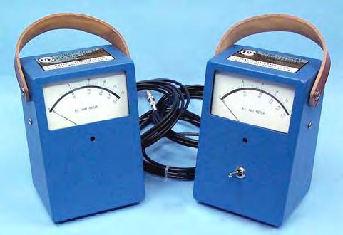
2 Specifications And Leading Particulars The and series Wattmeter is designed to work with any Coaxial Dynamics line section and the appropriate elements to accurately indicate the power in coaxial transmission lines. They are used to indicate power from 100mW to 100kW. They are all equipped with an easily read 4 ½ mirror backed triple scale meter Series Models With 5/10/25 Scales Model A High power 30uA meter in case for use with external single socket line sections. Model A High power 30uA meter in case with a FWD/RFL switch for use with external dual socket line sections. Models with 15/30/60 Scales Model A High power 30uA meter in case for use with external single socket line sections. Model A High power 30uA meter in case with a FWD/RFL switch for use with external dual socket line sections.
3 Specifications And Leading Particulars (cont.) Series Models With 5/10/25 Scales Model A High power 30uA meter in case for use with external single socket line sections. Model A High power 30uA meter in case with a FWD/RFL switch for use with external dual socket line sections. Models with 15/30/60 Scales Model A High power 30uA meter in case for use with external single socket line sections. Model A High power 30uA meter in case with a FWD/RFL switch for use with external dual socket line sections.
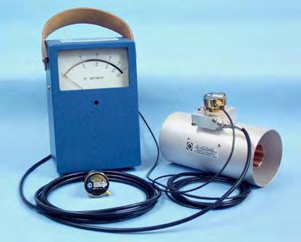
4 1. Purpose and Application General Description The series of Wattmeters are designed to measure power flow and match, when used with the appropriate line sections and elements. They are designed for use with CW, FM, AM, and analog TV systems. They are not for use with digital or pulsed applications. They normally are supplied with a 10 cable, but can be supplied with cables up to 200 without any loss of accuracy. The series of Wattmeters are designed to measure power flow and match, when used with the appropriate line sections and elements. They are designed for use with complex waveforms such as CDMA, DAB, DTV, IBOC as well as CW, FM, AM, and analog TV systems. They normally are supplied with 10 cables, but can be supplied with cables up to 200 without any loss of accuracy. 2. Description The series of Wattmeters includes a case with carrying strap, a shock-mounted mirror backed triple scale meter and cable(s) to attach to the line section. The case has four rubber feet on the base. The series of Wattmeters includes a case with carrying strap, a shock-mounted mirror backed triple scale meter and cables to attach to the line section and the element and a plug in wall power supply. The case has four rubber feet on the base. On the rear cover are SMA connectors used to supply DC power to the element via a length of shielded cable equipped with SMA connectors.
5 3. Theory of Operation General Description (cont.) The operation of the 88950/98950 series Wattmeters is based on the traveling wave concept of RF transmission. As RF is applied to a transmission line, there is a forward wave traveling from the transmitter to the load, and a reflected wave traveling from the load to the transmitter. The closer the load is matched to the transmission line the smaller the reflected wave will be. To determine the RF power dissipated in the load, it is necessary to determine the RF power of the forward wave and the RF power of the reflected wave. The difference between the two will be the power absorbed by the load. The interference between the forward and reflected waves produces a standing wave in the system. In the standing wave concept, VSWR (voltage standing wave ratio) is a widely used tool. There is a simple relation between forward power, reflected power and VSWR. Then Let W f represent forward power. W r represent reflected power. W r 1+ W f VSWR= 1- W r W f
6 General Description (cont.) For example: 1% reflected power is about 1.2:1 VSWR and 10% is about 2.0:1 VSWR. It can be seen that the VSWR is an index of the magnitude of the mismatch between the source and the load. The charts supplied can convert W f and W r to VSWR. When the line section and element are inserted in the transmission line the element is both capacitively and inductively coupled to the main line. Voltages proportional to the RF voltage and current in the main line are induced in the element circuitry. The coupling is so adjusted that the induced voltages add in the sensitive direction and cancel in the opposite direction. These voltages are rectified and the resulting DC current is applied to the meter, which is calibrated to represent the power in the main transmission line. In the series the RF voltages from the element are fed to some additional circuitry to provide the correct measurements of the complex waveforms. 1. General Procedure Operation To make readings with the Wattmeter, it is necessary to select and install a plug-in detector element of the proper power and frequency range, connect the cables to the line section in the transmission line and read the meter with the element in the forward and reverse direction. Subtraction of the reflected power from the forward power provides the power dissipated in the load. To determine VSWR, first determine the forward and reflected power and either use the formula or the charts provided.
7 Maintenance Maintenance of the 88950/98950 series of Wattmeters normally is limited to cleaning. The amount of cleaning necessary will depend on the environment the Wattmeter is operated in. Keeping an element in the socket of the line section will provide an effective seal against dust and dirt. When necessary, clean the element seat in the line section with a cotton swab. Pay particular attention to the bottom rim of the element seat and the body of the element. If necessary, the spring finger of the DC contact may be adjusted to make contact with the contact on the element. CAUTION: When making adjustments in the line section use extreme caution. The high RF voltages present in the line section can cause serious injury or death. Replacement Parts Common Parts to 88950/98950 series: Meter 5/10/25 scale A Meter 15/30/60 scale A Cable with DC connector: For series only: DC cable with SMA connectors: Wall Plug-in Power supply 120 VAC/60 HZ VAC/50 HZ 9726

8 Contact Our World-Wide Network of Distributors or Coaxial Dynamics for Information on All Our Products Loads RF Meters Filters Couplers Termination Wattmeters Directional Power Detectors Digital Wattmeters Peak/Average Wattmeters
Model Directional RF Wattmeter
 Model 81030 Directional RF Wattmeter Instruction Manual Table of Contents Paragraph Page Specifications and Leading Particulars.. 2 General Description 1. Purpose and Application...5 2. Description 5
Instruction Manual. Model USB Wattmeter
 Instruction Manual Model 81041 USB Wattmeter TABLE OF CONTENTS Specifications and Leading Particulars. 2 General Description 1. Purpose and Application 3 2. Description. 3 3. Theory of Operation... 4
Thruline RF Directional Wattmeters
 Portable Wattmeters BIRD S Famous ANALOG METER MODEL 43 Portable Wattmeter Power Range 100 mw - 10 kw using Bird Plug-in Elements.* Insertion VSWR with N Connectors 1.05 max. to 1000 MHz Finish Light Gray
Laboratory Grade Instruments Series & 4021 Power Meter SERIES Power Sensor
 Laboratory Grade Instruments 4020 Series & 4021 Power Meter Semiconductor 4020 SERIES Power Sensor 4021 4022 4024 4025 Power Input 300 mw to 1 kw 300 mw to 1 kw 3 W to 10 kw 3 W to 10 kw (1.2 kw max.)
Model Model Digital Power Meter. Digital Power Sensor Digital Display & Analog RF Systems
 Model 5000 Digital Power Meter Model 5010 Digital Power Sensor Digital Display & Analog RF Systems The NEW Industry Standa The NEW Industry Standard Hand-Hel Hand-Held RF Power Meter RF Power Met Serial
1 FUNCTIONAL DESCRIPTION WAY SPLITTER/INPUT BOARD FET RF AMPLIFIERS WAY POWER COMBINER VSWR CONTROL BOARD...
 CONTENTS 1 FUNCTIONAL DESCRIPTION...1 2 4-WAY SPLITTER/INPUT BOARD...2 3 FET RF AMPLIFIERS...3 4 4-WAY POWER COMBINER...4 5 VSWR CONTROL BOARD...5 6 ADJUSTMENT OF BIAS VOLTAGE TO ESTABLISH PROPER QUIESCENT
Broadband Power Amplifier
 601L Broadband Power Amplifier HIGH RF VOLTAGES MAY BE PRESENT AT THE OUTPUT OF THIS UNIT. All operating personnel should use extreme caution in handling these voltages and be thoroughly familiar with
LB680A Pulse Profiling USB PowerSensor+ Data Sheet
 Key PowerSensor+ Specifications 50 MHz to 20 GHz - 40 dbm to +20 dbm 2.8% Total Error* 1.20:1 VSWR (-21 db Return Loss) * Measuring a well matched DUT (-20 dbm @ 2 GHz) Measurement Capability Time Gated
Chapter 12: Transmission Lines. EET-223: RF Communication Circuits Walter Lara
 Chapter 12: Transmission Lines EET-223: RF Communication Circuits Walter Lara Introduction A transmission line can be defined as the conductive connections between system elements that carry signal power.
LB480A Pulse Profiling USB PowerSensor+ Data Sheet
 Key PowerSensor+ Specifications 50 MHz to 8 GHz (functional to 10 GHz) - 60 dbm to +20 dbm 1.95% Total Error* 1.09:1 VSWR (-27 db Return Loss) * Measuring a well matched DUT (-20 dbm @ 1 GHz) No Zero No
The Principle V(SWR) The Result. Mirror, Mirror, Darkly, Darkly
 The Result. Mirror, Mirror, Darkly, Darkly") The Principle V(SWR) The Result Mirror, Mirror, Darkly, Darkly 1 Question time!! What do you think VSWR (SWR) mean to you? What does one mean by a transmission line? Coaxial line Waveguide Water pipe Tunnel
The Principle V(SWR) The Result Mirror, Mirror, Darkly, Darkly 1 Question time!! What do you think VSWR (SWR) mean to you? What does one mean by a transmission line? Coaxial line Waveguide Water pipe Tunnel
Central Electronics Model 600L Linear Amplifier
 INTRODUCTION This manual has been reproduced by James Lawrence, NA5RC, a 600L owner. Text no longer applicable such as insurance claim with the carrier has been deleted. Some capitalization and grammar
LB679A CW and Pulse (Modulation) USB PowerSensor+ Data Sheet
 USB PowerSensor+ Data Sheet") Key PowerSensor+ Specifications 50 MHz to 20 GHz - 40 dbm to +20 dbm 2.8% Total Error* 1.20:1 VSWR (-21 db Return Loss) * Measuring a well matched DUT (-20 dbm @ 2 GHz) Key PowerSensor+ Capability Test
Key PowerSensor+ Specifications 50 MHz to 20 GHz - 40 dbm to +20 dbm 2.8% Total Error* 1.20:1 VSWR (-21 db Return Loss) * Measuring a well matched DUT (-20 dbm @ 2 GHz) Key PowerSensor+ Capability Test
Week 2 Lecture 1. Introduction to Communication Networks. Review: Analog and digital communications
 Week 2 Lecture 1 Introduction to Communication Networks Review: Analog and digital communications Topic: Internet Trend, Protocol, Transmission Principle Digital Communications is the foundation of Internet
LB480A Pulse Profiling USB PowerSensor+ Data Sheet
 Key PowerSensor+ Specifications 100 MHz to 8 GHz (functional to 10 GHz) -60 dbm to +20 dbm 1.95% Total Error* 1.09:1 VSWR (-27 db Return Loss) * Measuring a well matched DUT (-20 dbm @ 1 GHz) Measurement
Users Manual. 200W HF/50MHz Band Auto Antenna Tuner. Model HC-200AT
 Users Manual 200W HF/50MHz Band Auto Antenna Tuner Model HC-200AT Caution 1. Never remove or open the tuner cover while transmitting. When there is RF in the circuits of the tuner, there will be high voltage
AMPLIFIER RESEARCH... APPLICATION NOTE: 23
 AMPLIFIER RESEARCH... APPLICATION NOTE: 23 PRODUCTS THAT PROVIDE 200 V/m CW OR PM AT A DISTANCE OF 1 METER 1 The Amplifier / Antenna / Cell combinations shown in Table 1 provide various means of generating
Transmission lines. Characteristics Applications Connectors
 Transmission lines Characteristics Applications Connectors Transmission Lines Connect They allow us to conduct RF Signals between our station components, they connect: Transceivers Antennas Tuners Amplifiers
772D coaxial dual-directional coupler 773D coaxial directional coupler. 775D coaxial dual-directional coupler 776D coaxial dual-directional coupler
 72 772D coaxial dual-directional coupler 773D coaxial directional coupler 775D coaxial dual-directional coupler 776D coaxial dual-directional coupler 777D coaxial dual-directional coupler 778D coaxial
3100LA Broadband Power Amplifier
 3100LA Broadband Power Amplifier HIGH RF VOLTAGES MAY BE PRESENT AT THE OUTPUT OF THIS UNIT. All operating personnel should use extreme caution in handling these voltages and be thoroughly familiar with
OPERATION & SERVICE MANUAL FOR FC 110 AC POWER SOURCE
 OPERATION & SERVICE MANUAL FOR FC 100 SERIES AC POWER SOURCE FC 110 AC POWER SOURCE VERSION 1.3, April 2001. copyright reserved. DWG No. FC00001 TABLE OF CONTENTS CHAPTER 1 INTRODUCTION... 1 1.1 GENERAL...
PI-150 Broadband Power Indicator
 PI-150 Broadband Power Indicator HIGH RF VOLTAGES MAY BE PRESENT AT THE PORTS OF THIS UNIT. All operating personnel should use extreme caution in handling these voltages and be thoroughly familiar with
411LA Broadband Power Amplifier
 411LA Broadband Power Amplifier HIGH RF VOLTAGES MAY BE PRESENT AT THE OUTPUT OF THIS UNIT. All operating personnel should use extreme caution in handling these voltages and be thoroughly familiar with
User s Guide. MultiView Series Digital MultiMeters Models: MV110 MV120 MV130
 User s Guide MultiView Series Digital MultiMeters Models: MV110 MV120 MV130 WARRANTY EXTECH INSTRUMENTS CORPORATION warrants this instrument to be free of defects in parts and workmanship for one year
2100L Broadband Power Amplifier
 2100L Broadband Power Amplifier HIGH RF VOLTAGES MAY BE PRESENT AT THE OUTPUT OF THIS UNIT. All operating personnel should use extreme caution in handling these voltages and be thoroughly familiar with
High-speed programmable attenuator MAT800
 High-speed programmable attenuator MAT800 Windows98/Me/2000/XP/Vista/7(32bit) correspondence GP-IB, RS-232C and software for making attenuation program are standard accessories. Optimum for evaluation
A 500 Broadband Power Amplifier
 A 500 Broadband Power Amplifier HIGH RF VOLTAGES MAY BE PRESENT AT THE OUTPUT OF THIS UNIT. All operating personnel should use extreme caution in handling these voltages and be thoroughly familiar with
PI-10 Broadband Power Indicator
 PI-10 Broadband Power Indicator HIGH RF VOLTAGES MAY BE PRESENT AT THE PORTS OF THIS UNIT. All operating personnel should use extreme caution in handling these voltages and be thoroughly familiar with
TYPE 874-GAL ADJUSTABLE ATTENUATOR
 OPERATING INSTRUCTIONS TYPE 874-GAL ADJUSTABLE ATTENUATOR DESCRIPTION The Type 874-GAL Adjustable Attenuator is of the wave-guidebelow-cutoff type operating in the TE 1 mode (inductive coupling). The waveguide
GT-1050A 2 GHz to 50 GHz Microwave Power Amplifier
 Established 1981 Advanced Test Equipment Rentals www.atecorp.com 800-404-ATEC (2832) Giga-tronics GT-1050A Microwave Power Amplifier GT-1050A 2 GHz to 50 GHz Microwave Power Amplifier Operation Manual
Voltage Sensors URV5-Z
 Data sheet Version 05.00 Voltage Sensors URV5-Z May 2005 Universal voltage measurements from RF to microwaves The voltage sensors of the URV5-Z series are indispensable tools in RF and microwave laboratories,
MBM 307A / 407A PF Automatic Folders
 MBM 307A / 407A PF Automatic Folders Instruction Manual Provided By http://www.mybinding.com http://www.mybindingblog.com OPERATION MANUAL MBM 307A / 407A AUTOMATIC FOLDERS 1-800-223-2508 www.mbmcorp.com
AMPLIFIER RESEARCH... APPLICATION NOTE: 20
 AMPLIFIER RESEARCH... APPLICATION NOTE: 20 AMPLIFIER RESEARCH PRODUCTS THAT PROVIDE 20 V/m CW OR PM AT A DISTANCE OF 1 METER 1 The Amplifier / Antenna / Cell combinations shown in Table 1 provide various
MFJ-949E. tuner antenowy skrzynka antenowa. Instrukcja obsługi. importer:
 Instrukcja obsługi MFJ-949E tuner antenowy skrzynka antenowa importer: PRO-FIT Centrum Radiokomunikacji InRadio ul. Puszkina 80 92-516 Łódź tel: 42 649 28 28 e-mail: biuro@inradio.pl www.inradio.pl MFJ-949E
Transmission Line Signal Sampling By Don Steinbach, AE6PM
 Transmission Line Signal Sampling By Don Steinbach, AE6PM When I was finalizing the mechanical layout of my remotely-operated 3-position coaxial antenna switch (Fig. 1), I wanted to include a way to bring
Transmission lines carry RF
 Transmission Line asics Technical techniques: primer for transmission lines Part I n understanding of transmission lines and tips on using them as transformers and filters can help techs properly configure
MFJ-835 RF Ammeter. Introduction. Uses
 MFJ-835 RF Ammeter Introduction Congratulations on purchasing the MFJ-835 Balanced Line RF Ammeter. The MFJ-835 is designed for measuring balanced RF feedline current on 1.8-30 MHz while having low interaction
Electrical Data Voltage Supply. 56dB nom. ±2dB (fine ADJ available) Power Out compression) Min. 600W (Typ. 700W) Input Return Loss
 Power Out compression) Min. 600W (Typ. 700W) Input Return Loss") AU100-D is a full LD-MOS Broadcast Power Amplifier designed for both digital and analog applications. The unit is the state of the art in terms of easy assembly, reliability and performances. The complete
AU100-D is a full LD-MOS Broadcast Power Amplifier designed for both digital and analog applications. The unit is the state of the art in terms of easy assembly, reliability and performances. The complete
Broadband Current Probe Series Operation Manual
 Broadband Current Probe Series Operation Manual 1 TABLE OF CONTENTS INTRODUCTION 3 GENERAL INFORMATION 4 OPERATING INSTRUCTIONS 5 FORMULAS 6 MAINTENANCE 7 WARRANTY 8 2 INTRODUCTION CURRENT PROBE SPECIFICATIONS
PR-E 3 -SMA. Super Low Noise Preamplifier. - Datasheet -
 PR-E 3 -SMA Super Low Noise Preamplifier - Datasheet - Features: Low Voltage Noise (0.6nV/ Hz, @ 1MHz single channel mode) Low Current Noise (12fA/ Hz @ 10kHz) f = 0.5kHz to 4MHz, A = 250V/V (customizable)
1140LA Broadband Power Amplifier
 1140LA Broadband Power Amplifier HIGH RF VOLTAGES MAY BE PRESENT AT THE OUTPUT OF THIS UNIT. All operating personnel should use extreme caution in handling these voltages and be thoroughly familiar with
CALIBRATED IMPULSE GENERATOR MODEL CIG khz 1 GHz
 INSTRUCTION MANUAL CALIBRATED IMPULSE GENERATOR MODEL CIG-25 10 khz 1 GHz INSTRUCTION MANUAL THIS INSTRUCTION MANUAL AND ITS ASSOCIATED INFORMATION IS PROPRIETARY. UNAUTHORIZED REPRODUCTION IS FORBIDDEN.
Amateur Extra Manual Chapter 9.4 Transmission Lines
 9.4 TRANSMISSION LINES (page 9-31) WAVELENGTH IN A FEED LINE (page 9-31) VELOCITY OF PROPAGATION (page 9-32) Speed of Wave in a Transmission Line VF = Velocity Factor = Speed of Light in a Vacuum Question
MFJ-834 RF Ammeter. Introduction. Uses
 MFJ-834 RF Ammeter Introduction Congratulations on purchasing the MFJ-834 RF Ammeter. The MFJ-834 is designed for measuring in-line RF feedline current on 1.8-30 MHz while having low interaction on the
INSTALLATION MANUAL. CTA-30RK-550 Rack Mount Distribution Amplifier
 INSTALLATION MANUAL CTA-30RK-550 Rack Mount Distribution Amplifier 1 PACKAGE CONTENTS This package contains: One CTA-30RK-550 Rack Mount Distribution Amplifier One CTA-30RK-550 instruction manual PRODUCT
Agilent 87222C/D/E Coaxial Transfer Switches dc to 26.5, 40, 50 GHz
 Agilent 87C/D/E Coaxial Transfer Switches dc to 6.5, 0, 50 GHz Technical Overview High Performance Transfer Switches for Micro wave and RF Instrumentation and Systems Exceptional repeatability for more
POWER LINE IMPEDANCE STABLIZATION NETWORK (LISN) MODEL PLISN-25/2. 5 khz 1 GHz
 MODEL PLISN-25/2. 5 khz 1 GHz") INSTRUCTION MANUAL POWER LINE IMPEDANCE STABLIZATION NETWORK (LISN) MODEL PLISN-25/2 5 khz 1 GHz INSTRUCTION MANUAL THIS INSTRUCTION MANUAL AND ITS ASSOCIATED INFORMATION IS PRO- PRIETARY. UNAUTHORIZED
INSTRUCTION MANUAL POWER LINE IMPEDANCE STABLIZATION NETWORK (LISN) MODEL PLISN-25/2 5 khz 1 GHz INSTRUCTION MANUAL THIS INSTRUCTION MANUAL AND ITS ASSOCIATED INFORMATION IS PRO- PRIETARY. UNAUTHORIZED
DLVP A OPERATOR S MANUAL
 DLVP-50-300-3000A OPERATOR S MANUAL DYNALOAD DIVISION 36 NEWBURGH RD. HACKETTSTOWN, NJ 07840 PHONE (908) 850-5088 FAX (908) 908-0679 TABLE OF CONTENTS INTRODUCTION...3 SPECIFICATIONS...5 MODE SELECTOR
Application Note 5525
 Using the Wafer Scale Packaged Detector in 2 to 6 GHz Applications Application Note 5525 Introduction The is a broadband directional coupler with integrated temperature compensated detector designed for
IEM-75 UHF wireless system. user manual
 IEM-75 UHF wireless system user manual Musikhaus Thomann Thomann GmbH Hans-Thomann-Straße 1 96138 Burgebrach Germany Telephone: +49 (0) 9546 9223-0 E-mail: info@thomann.de Internet: www.thomann.de 02.09.2015,
VECTRONICS HFT-1500 Digital Bargraph Antenna Tuner
 Table of Contents FEATURES... 1 SPECIFICATIONS... 1 FRONT PANEL INDICATORS AND CONTROLS... 1 CONTROLS... 1 REAR PANEL CONNECTORS... 1 OTHER... 2 CONTOLS / CONNECTORS... 2 FRONT PANEL FUNCTIONS... 2 REAR
BTM Series Pulsed RF Power Amplifier Modules. Application Note
 BTM Series Pulsed RF Power Amplifier Modules Application Note Tomco BT Series Pulsed RF Amplifier Modules - Application note Contents Contents...2 Amplifier Safety Precautions...3 Hazardous Materials Warning:...4
Array Solutions Four Square Array Manual and User s Guide
 Array Solutions Four Square Array Manual and User s Guide Array Solutions Four Square Array Pattern Steering System Congratulations! You have selected one of the finest phased array steering systems made.
DEPARTMENT OF THE ARMY TECHNICAL MANUAL OPERATOR, ORGANIZATIONAL, FIELD AND DEPOT MAINTENANCE MANUAL
 TM -6625-446-5 DEPARTMENT OF THE ARMY TECHNICAL MANUAL OPERATOR, ORGANIZATIONAL, FIELD AND DEPOT MAINTENANCE MANUAL WATTMETER AN/URM-20 This copy is a reprint which includes current pages from Changes,
INSTRUCTION SHEET WIDEBAND POWER SENSOR MODEL Copyright 2008 by Bird Electronic Corporation Instruction Book P/N Rev.
 INSTRUCTION SHEET WIDEBAND POWER SENSOR MODEL 5012 Copyright 2008 by Bird Electronic Corporation Instruction Book P/N 920-5012 Rev. C Description The Bird 5012 Wideband Power Sensor (WPS) is a Thruline
Bird Model 7022 Statistical Power Sensor Applications and Benefits
 Applications and Benefits Multi-function RF power meters have been completely transformed since they first appeared in the early 1990 s. What once were benchtop instruments that incorporated power sensing
MODEL FS-4 INSTRUCTION MANUAL R.L. DRAKE COMPANY, MIAMISBURG, OHIO, U.S.A.
 MODEL FS-4 F R E Q U E N C Y S Y N T H E S I Z E R INSTRUCTION MANUAL R.L. DRAKE COMPANY, MIAMISBURG, OHIO, U.S.A. LIMITED WARRANTY R. L. DRAKE COMPANY warrants to the original purchaser that this product
Vectronics VC-300D DIGITAL BARGRAPH ANTENNA TUNER
 Vectronics VC-300D DIGITAL BARGRAPH ANTENNA TUNER FEATURES The Vectronics VC-300D Antenna Tuner optimizes the performance of your antenna and transmitter, receiver, or transceiver by providing adjustable
Practical Tricks with Transformers. Larry Weinstein K0NA
 Practical Tricks with Transformers Larry Weinstein K0NA Practical Tricks with Transformers Quick review of inductance and magnetics Switching inductive loads How many voltages can we get out of a $10 Home
433 & 443 Series INTELLIGENT RELAY SP3T & SP4T IN-LINE Multithrow Switches
 433 & 443 Series INTELLIGENT RELAY SP3T & SP4T IN-LINE Multithrow Switches Available with two types of internal drive electronics (Binary Decoding or MOSFET Pulse Latching), these SP3T and SP4T IN-LINE
The Amazing MFJ 269 Author Jack Tiley AD7FO
 The Amazing MFJ 269 Author Jack Tiley AD7FO ARRL Certified Emcomm and license class Instructor, Volunteer Examiner, EWA Technical Coordinator and President of the Inland Empire VHF Club What Can be Measured?
USER'S MANUAL DMR-6700
 USER'S MANUAL Multimeter True RMS DMR-6700 CIRCUIT-TEST ELECTRONICS www.circuittest.com Introduction This meter measures AC/DC Voltage, AC/DC Current, Resistance, Capacitance, Frequency (electrical & electronic),
COM-POWER OPERATION MANUAL ACS W
 COM-POWER OPERATION MANUAL For the ACS-250-100W 150 khz to 250 MHz 100W Power Amplifier Page 1 of 15 MANUAL_ACS-250-100W Rev. M02.15 Table of Contents Important Safety Precautions.....3 Introduction..5
MICROWAVE MICROWAVE TRAINING BENCH COMPONENT SPECIFICATIONS:
 Microwave section consists of Basic Microwave Training Bench, Advance Microwave Training Bench and Microwave Communication Training System. Microwave Training System is used to study all the concepts of
8/11-N EDP-No ctn qty. 10 / 1 piece. 8/12-N EDP-No ctn qty. 10 / 1 piece. 8/50-N EDP-No ctn qty. 10 / 1 Set
 Do it yourself Coax plug 75 ohm 8/11-N EDP-No. 43000 Coax socket 75 ohm 8/12-N EDP-No. 43001 Plug set for aerial cable Coax plug + coax socket 8/50-N EDP-No. 43002 / 1 Set Coax double plug Coax plug
ALM473 DUAL MONO \ STEREO AUDIO LEVEL MASTER OPERATION MANUAL IB
 ALM473 DUAL MONO \ STEREO AUDIO LEVEL MASTER OPERATION MANUAL IB6408-01 TABLE OF CONTENTS GENERAL DESCRIPTION 2 INSTALLATION 2,3,4 CONNECTION AND SETUP 4,5,6,7 FUNCTIONAL DESCRIPTION 8,9 MAINTENANCE 9
free solo PT UHF wireless system user manual
 free solo PT UHF wireless system user manual Musikhaus Thomann e.k. Treppendorf 30 96138 Burgebrach Germany Telephone: +49 (0) 9546 9223-0 E-mail: info@thomann.de Internet: www.thomann.de 22.01.2013 Table
Model 3140B BiConiLog Antenna User Manual
 Model 3140B BiConiLog Antenna User Manual Model 3140B mounted onto a 7-TR tripod (not included) ETS-Lindgren L.P. reserves the right to make changes to any product described herein in order to improve
DSTS-3B DEPTHSOUNDER TEST SET OPERATOR S MANUAL
 Page 1 1.0 INTRODUCTION DSTS-3B DEPTHSOUNDER TEST SET OPERATOR S MANUAL The DSTS-3B is a full-featured test set designed for use with all types of echo sounders from small flashers to large commercial
MFJ-969 Versa Tuner II Instruction Manual
 MFJ-969 Versa Tuner II Instruction Manual General Information The MFJ-969 is a 300 watt RF output power antenna tuner that will match any transmitter or transceiver to virtually any antenna. Peak or average
MFJ-836H SWR/Wattmeter and RF Ammeter
 Introduction MFJ8H SWR/Wattmeter and RF Ammeter The MFJ8H is an allinone true peak reading SWR/Wattmeter with a built in RF Ammeter designed to operate on.80 MHz. The SWR/Wattmeter uses our TrueActive
Current Probes. User Manual
 Current Probes User Manual ETS-Lindgren Inc. reserves the right to make changes to any product described herein in order to improve function, design, or for any other reason. Nothing contained herein shall
Safety Warnings Features Specifications Instrument Layout Operation Preparation AC Current Measurement How to Use Peak Hold Function How to Use The
 Safety Warnings Features Specifications Instrument Layout Operation Preparation AC Current Measurement How to Use Peak Hold Function How to Use The Frequency Selector Switch How to Use Data Hold Function
Technician License. Course
 Technician License Course Technician License Course Chapter 4 Lesson Plan Module - 10 Practical Antennas The Dipole Most basic antenna The Dipole Most basic antenna The Dipole Total length is ½ wavelength
A TRANSMISSION LINE BALANCE TEST METER
 by Lloyd Butler VK5BR with modifications by Phil Storr VK5SRP. Here is a simple meter to check the balance of currents running in the two legs of a transmission line. It can be used to check the balance
free solo HT UHF wireless system user manual
 free solo HT UHF wireless system user manual Musikhaus Thomann e.k. Treppendorf 30 96138 Burgebrach Germany Telephone: +49 (0) 9546 9223-0 E-mail: info@thomann.de Internet: www.thomann.de 22.01.2013 Table
MFJ ENTERPRISES 300 INDUSTRIAL PARK STARKVILLE, MS USA
 MFJ-819 MOBILE SWR/WATTMETER INSTRUCTION MANUAL PLEASE READ THIS MANUAL BEFORE OPERATING THIS EQUIPEMENT! MFJ ENTERPRISES 300 INDUSTRIAL PARK STARKVILLE, MS 39759 USA www.mfjenterprises.com 662-323-5869
A Selection of R.F. Wattmeters optimized for console, remote, and mobile applications.
 Watt/SWR Meter (2 and 4 channel products Peak/Average on forward and Reflected). Modulation Scope. (All models) Modulation Spectrum Analyzer. (All models) Station Voltage/Current Monitor (WN-2 only). Four
Broadband Current Probe Series Operation Manual
 Broadband Current Probe Series Operation Manual 1 TABLE OF CONTENTS WARRANTY 3 INTRODUCTION 4 GENERAL INFORMATION 5 OPERATING INSTRUCTIONS 6 FORMULAS 7 MAINTENANCE 8 2 WARRANTY INFORMATION A.H. Systems
and GHz. ECE Radiometer. Technical Description and User Manual
 E-mail: sales@elva-1.com http://www.elva-1.com 26.5-40 and 76.5-90 GHz ECE Radiometer Technical Description and User Manual November 2008 Contents 1. Introduction... 3 2. Parameters and specifications...
Application Note (Revision NEW) Original Instructions. EMI Control in Electronic Governing Systems
 Original Instructions. EMI Control in Electronic Governing Systems") Application Note 50532 (Revision NEW) Original Instructions EMI Control in Electronic Governing Systems General Precautions Read this entire manual and all other publications pertaining to the work to
Application Note 50532 (Revision NEW) Original Instructions EMI Control in Electronic Governing Systems General Precautions Read this entire manual and all other publications pertaining to the work to
PRA Series of Radio and TV Amplifier Power Supplies
 PRA Series of Radio and TV Amplifier Power Supplies The PRA 420 is an antenna power supply, low noise MMIC amplifier and splitter combination to supply up to 24 Shipboard Radios and /or TV Receivers. It
TITANIUM SERIES R 51 PART NUMBER SELECTION. High Performance Multiport Switches. Our Most Important Connection is with You.
 PART NUMBER SELECTION Models: 2: Without 50 Ω terminations 4: With 50 Ω terminations RF Connectors: 3: SMA up to 6 GHz 4: SMA up to 20 GHz F: SMA up to 26.5 GHz 8: SMA 2.9 up to 40 GHz (1) Radiall s TITANIUM
8450 Series CellGuard TM Power / VSWR Monitors
 8450 Series TM Power / VSWR Monitors Precision Power and VSWR Measurements via Integral High Directivity Coupler (35 db typical) and Imbedded Microprocessor. True RMS Power Measurement over a 30 db Dynamic
Contents 1. General instructions. 1.1 Precautions safety measures Protection mechanisms. 2. Description. 2.1 Instrument Familiarization. 2.
 Contents 1. General instructions. 1.1 Precautions safety measures... 1.2 Protection mechanisms. 2. Description. 2.1 Instrument Familiarization. 2.2 LCD Display 2.3 Keypad. 3. Function description. 3.1
SIGNAL GENERATORS. MG3633A 10 khz to 2700 MHz SYNTHESIZED SIGNAL GENERATOR GPIB
 SYNTHESIZED SIGNAL GENERATOR MG3633A GPIB For Evaluating of Quasi-Microwaves and Measuring High-Performance Receivers The MG3633A has excellent resolution, switching speed, signal purity, and a high output
Performance evaluation of two RF power limiters based on PIN diodes
 Performance evaluation of two RF power limiters based on PIN diodes Marta Bautista Durán, José A. López-Pérez December 2017 IT-CDT 2017-19 Observatorio de Yebes Apdo. 148, E-19080 Guadalajara SPAIN 1 1
IEM 100 UHF wireless system. user manual
 IEM 100 UHF wireless system user manual Musikhaus Thomann Thomann GmbH Hans-Thomann-Straße 1 96138 Burgebrach Germany Telephone: +49 (0) 9546 9223-0 E-mail: info@thomann.de Internet: www.thomann.de 18.06.2018,
Data Sheet HFBR-1506AFZ/HFBR-2506AFZ. Full Metal Fiber Optic SMA Transmitters and Receivers for 16 MBd SERCOS Applications. Description.
 HFBR-0AFZ/HFBR-20AFZ Full Metal Fiber Optic SMA Transmitters and Receivers for MBd SERCOS Applications Data Sheet Description SERCOS, an acronym for SErial Realtime COmmunications Systems, is a standard
OPERATION MANUAL MBM 207M MANUAL FOLDER
 OPERATION MANUAL MBM 207M MANUAL FOLDER 1-800-223-2508 www.mbmcorp.com 1 Safety Instructions Definition of Symbols and Notes The following names and signs stand for possible dangers: Danger This symbol
Data Sheet. HFBR-1506AMZ/HFBR-2506AMZ Fiber Optic SMA Transmitters and Receivers for 16 MBd SERCOS Applications. Description. Features.
 HFBR-0AMZ/HFBR-20AMZ Fiber Optic SMA Transmitters and Receivers for MBd SERCOS Applications Data Sheet Description SERCOS, an acronym for SErial Realtime COmmunications Systems, is a standard digital interface
BIRD ELECTRONIC CORPORATION
 BIRD ELECTRONIC CORPORATION Application Note Straight Talk About Directivity Application Note: Effects of Directivity on Power, VSWR and Return Loss Measurement Accuracy, / 475-APP-0404RV2 INTRODUCTION
TWS 16 BT UHF wireless system. user manual
 TWS 16 BT UHF wireless system user manual Musikhaus Thomann e.k. Treppendorf 30 96138 Burgebrach Germany Telephone: +49 (0) 9546 9223-0 email: info@thomann.de Internet: www.thomann.de 09.03.2012 Table
ST-CCTV-VBAC8 8-Channel Active UTP Video Receiver
 INSTALLATION MANUAL 8-Channel Active UTP Video Receiver Copyright North American Cable Equipment, Inc. 1 PACKAGE CONTENTS This package contains: One 8-channel active UTP video receiver One AC power cord
TWS 16 HT UHF wireless system. user manual
 TWS 16 HT UHF wireless system user manual Musikhaus Thomann e.k. Treppendorf 30 96138 Burgebrach Germany Telephone: +49 (0) 9546 9223-66 E-mail: info@thomann.de Internet: www.thomann.de 30.04.2012 Table
1 KW TOTALLY SOLID STATE DIFFERENTIAL GPS TRANSMITTER ( khz)
") GPS1000 1 KW TOTALLY SOLID STATE DIFFERENTIAL GPS TRANSMITTER (282-326 khz) NAUTEL has developed the GPS1000 as an extremely efficient and highly reliable transmitter especially suited for use at remote
GPS1000 1 KW TOTALLY SOLID STATE DIFFERENTIAL GPS TRANSMITTER (282-326 khz) NAUTEL has developed the GPS1000 as an extremely efficient and highly reliable transmitter especially suited for use at remote
TWS 16 PT UHF wireless system. user manual
 TWS 16 PT UHF wireless system user manual Musikhaus Thomann Thomann GmbH Hans-Thomann-Straße 1 96138 Burgebrach Germany Telephone: +49 (0) 9546 9223-0 E-mail: info@thomann.de Internet: www.thomann.de 17.11.2015,
Introduction. Understanding Power Ratings. Peak Reading SWR/Wattmeter
 Introduction The MFJ-962D is a "T" network roller inductor tuner with built-in antenna switching, RF power and SWR metering and a 1:1 balun. The largest amplifiers that can safely be used include the Heathkit
MFJ-941E Versa Tuner II GENERAL INFORMATION:
 GENERAL INFORMATION: MFJ VERSA TUNER II The MFJ-941E is designed to match virtually any transmitter to any antenna, including dipoles, inverted-vees, verticals, mobile whips, beams, random wires, and others
PA FAN PLATE ASSEMBLY 188D6127G1 SYMBOL PART NO. DESCRIPTION. 4 SBS /10 Spring nut. 5 19A702339P510 Screw, thread forming, flat head.
 MAINTENANCE MANUAL 851-870 MHz, 110 WATT POWER AMPLIFIER 19D902797G5 TABLE OF CONTENTS Page DESCRIPTION.............................................. Front Page SPECIFICATIONS.................................................