CALF Configurable Audio Limiter Filter
|
|
|
- Sophie Melinda Bradley
- 5 years ago
- Views:
Transcription

1 CALF Configurable Audio Limiter Filter
2
3 CALF Parts List Package Contents PCB Calf Front Panel PCB CALF Main Board Enclosure w/ Panels Components Front Panel Components Chassis Components Power Supply Components Amplifier Components LED Driver/Detector Components Buffer/Limiter Components 700Hz Filter Components Hardware Front Panel Components Qty Ref Description Markings 1 P1 Header 10 pin 1 P2 Header 2 pin D1 2 D2 LED 3mm Green 1 D4 LED 3mm Red 1 D3 LED 3mm Yellow RV1 2 R Potentiometer 10K R1 R2 R3 4 R4 Resistor 1/4W 5% 2.2K 1 SW1 Switch Pushbutton Latching DPDT-8X8MM Red-Red-Red-Gold Chassis Components Qty Ref Description Markings 1 Switch Knob 1 SW101 Switch Rotary DP6T 9 Wire 22ga Strnd (ft) BLACK 3 Wire 22ga Strnd (ft) BLUE 3 Wire 22ga Strnd (ft) RED 3 Wire 22ga Strnd (ft) WHITE 4 2 Wire Ribbon 10 conductor Jack Chassis Mono 3.5mm 1 Jack Chassis Power 2.1mm 2 Plug Mono 3.5mm 1 Plug Power 2.1mm
4 POWER SUPPLY COMPONENTS Qty Ref Description Markings 1 P105 Connector Female Right Angle.1ls 10 pin 1 P107 Terminal Block 5mm TE2 1 D101 Diode_400 1N4007 R102 2 R103 Resistor_MF_1/4W_1% 22K Red-Red-Black-Red-Brown 1 C106 Capacitor Electrolytic 5x11mm.1ls 100uF 16V C107 2 C108 Capacitor Electrolytic 5x11mm.1ls 10uF 50V 1 C102 Capacitor_Electrolytic_8x11mm_138ls 220uF 25V 1 U101 IC_TO92 78L09 Amplifier Components Qty Ref Description Markings 1 R101 Resistor_MF_1/4W_1% 100K 1% Brown-Black-Black-Orange-Brown 1 R301 Resistor_MF_1/4W_1% 10K 1% Brown-Black-Black-Red-Brown 1 R302 Resistor 1/4W 5% 10 Brown-Black-Black-Gold C302 2 C304 Capacitor ceramic.2ls 47n.047uF 473 C101 2 C305 Capacitor Electrolytic 5x11mm.1ls 10uF 50V C301 2 C303 Capacitor_Electrolytic_8x11mm_138ls 220uF 25V 1 U301 IC DIP8 LM386N-1 1 U301s Socket IC DIP 8 Pin 1 P106 Connector Female Right Angle.1ls 2 pin 1 A Header 1 pin 1 P102 Terminal Block 5mm TE2 LED Driver/Detector Qty Ref Description Markings 1 C202 Capacitor ceramic.2ls 100n.1uF C103 Capacitor ceramic.2ls 10n.01uF D203 Diode_300 1N R212 Resistor 1/4W 5% 1.2K Brown-Red-Red-Gold R211 2 R213 Resistor 1/4W 5% 1.8K 1 R209 Resistor 1/4W 5% 15K 1 R207 Resistor 1/4W 5% 1K 1 R208 Resistor 1/4W 5% 220K 1 R206 Resistor 1/4W 5% 4.7K 1 R210 Resistor_MF_1/4W_1% 10K 1% 1 R205 Resistor_MF_1/4W_1% 2K 1% 1 U202 IC DIP14 LM324 1 U202s Socket IC DIP 14 Pin Brown-Grey-Red-Gold Brown-Green-Orange-Gold Brown-Black-Red-Gold Red-Red-Yellow-Gold Yellow-Violet-Red-Gold Brown-Black-Black-Red-Brown Red-Black-Black-Brown-Brown
5 Buffer/Limiter Qty Ref Description Markings 1 R201 Resistor_MF_1/4W_1% 2K 1% Red-Black-Black-Brown-Brown R202 2 R204 Resistor 1/4W 5% 1K Brown-Black-Red-Gold 1 R203 Resistor_MF_1/4W_1% 10K 1% Brown-Black-Black-Red-Brown 1 R01 Trimmer 6mm Horiz 250K 254 D201 2 D202 Diode_300 1N4148 C104 2 C105 Capacitor ceramic.2ls 10n.01uF C201 Capacitor_Mylar_ n.47uF 474 U201 2 U401 IC DIP14 TL084 U201s 2 U401s Socket IC DIP 14 Pin 1 P101 Terminal Block 5mm TE2 7 Shorting Block JP201 JP202 JP401 JP402 JP403 JP404 7 JP405 Header 2 pin F3 2 BUF Header 1 pin 1 P113 Header 4 pin Headers shipped as break away strips Small Hardware Qty Ref Description Markings 2 Hardware #4 standoff Hardware #4 standoff Hardware 4-40 nut 2 Hardware L Bracket Hardware Screw 4-40x Hardware Washer Lock #4 Int Tooth 1 Switch Caps
6 700Hz Filter Qty Ref Description Markings 6 FILTERS Header Female 10 pin straight 12 6 Header 5 pin PCB CALF EARS Shipped as 3 20 pin strips C401 C402 C403 C404 C405 6 C406 Capacitor_Mylar_170 10n.01uF 5% 103 C407 C408 C409 C410 C411 6 C412 Capacitor_Mylar_200 22n.022uF 5% R417 Resistor_MF_1/4W_1% 1.3K Brown-Orange-Black-Brown-Brown 1 R403 Resistor_MF_1/4W_1% 100K 1% Brown-Black-Black-Orange-Brown R404 2 R407 Resistor_MF_1/4W_1% 22K 1 R416 Resistor_MF_1/4W_1% 2K 1% 1 R405 Resistor_MF_1/4W_1% 33K 1% 1 R414 Resistor_MF_1/4W_1% 43K 1% R401 2 R406 Resistor_MF_1/4W_1% 47K 1% 1 R402 Resistor_MF_1/4W_1% 68K 1% 1 R408 Resistor_MF_1/4W_1% 10K 1% 1 R412 Resistor_MF_1/4W_1% 120K 1% 1 R413 Resistor_MF_1/4W_1% 27K 1% R410 2 R415 Resistor_MF_1/4W_1% 56K 1% 1 R409 Resistor_MF_1/4W_1% 5K6 1% 1 R411 Resistor_MF_1/4W_1% 82K 1% 1 R418 Resistor_MF_1/4W_1% 910 1% Red-Red-Black-Red-Brown Red-Black-Black-Brown-Brown Orange-Orange-Black-Red-Brown Yellow-Orange-Black-Red-Brown Yellow-Violet-Black-Red-Brown Blue-Grey-Black-Red-Brown Brown-Black-Black-Red-Brown Brown-Red-Black-Orange-Brown Red-Voilet-Black-Red-Brown Green-Blue-Black-Red-Brown Green-Blue-Black-Brown-Brown Grey-Red-Black-Red-Brown White-Brown-Black-Black-Brown
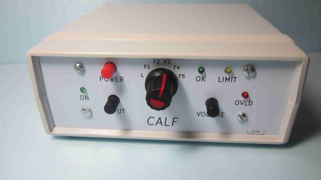
7 CALF the CW Audio Limiter Filter Combines an audio limiter circuit along with up to 6 stages of bandpass filtering to aid in SSB/SWL and CW receiving. Filtering bandwidth ranges from 700Hz to less than 100Hz while the limiter circuit can be used to reduce large static crashes or aid in weak signal reception. A special thanks to Glen, KK4LPG, for your encouragement and guidance to help make this project a reality. Features: Limiter helps to reduce crashes from QRN or can aid in weak signal reception 6 stages of Op Amp filtering, 5 switch selectable, offering various bandwidths from Hz on a 700Hz center frequency Built in 1W Audio amplifier drives headphones or a small speaker Controls mounted on a front panel PCB for ease of use Experimental options: Stages can be split and re-arranged via jumper blocks Want to put the limiter in the middle of the filter stages? No problem! Optional IC Sockets are included to change and experiment with different R/C values and filter modes Make Bandpass, Lowpass or Highpass filter stages! This kit was designed using through hole components and enlarged PCB solder pads for ease of assembly. Included with the kit are several components such as stand-offs, plugs, and jacks to complete the project. Just add your own case! The following tools are recommended: Pencil type soldering iron and solder. Needle nose pliers, small surgical clamps, small vice, Wire cutters/strippers, exacto knife Magnifier Glass (optional but helpful) Slotted screwdrivers Scrap wire 1 small piece approximately 2-3", just about any guage from will work. Digital Multi-Meter (DMM) Highly Recommended to test 1% resistor values! Oscilloscope & AF Signal generator (optional) Power Source/supply 12-15V Small Rotary Tool or Jewelers saw (optional for case installation) Construction notes: Familiarize yourself with components using the included parts list. TIP: Not sure what part is what? The following sources have great articles on component identification and building techniques. Almost any copy of the ARRL Handbook published within the last 25 years. The GQRP web site: All parts are mounted on the top side of the PCB except headers P1 and P2 on the front panel PCB. Solder and trim the excess leads after installing each component. 1 Of 24
8 TIP: Not sure how to solder? There are many excellent videos on the internet. Check out sites such as Sparkfun.com, adafruit.com, and electronics123.com. Parts of better quality may be substituted in a few cases. For example a 1K 5% resistor (Brown-Black-Red-Gold) may be substituted with a 2% (Brown-Black-Red-Red). We have tried to note this in the parts list. 5 band 1% resistors can be a little confusing to read at times. It's recommended to measure them with a DMM before soldering in place. For example this kit has a 100K resistors (brownblack-black-orange-brown) which looks similar to the 1.3K resistor (brown-orange-blackbrown-brown). Ceramic capacitors may be either the traditional "brown" disc type or monolithic "yellow" variety. Mylar capacitors are typically larger, rectangular, and green in color. These devices usually have a better tolerance (5%) than ceramic types. Observe polarity when installing electrolytic capacitors. The square pad is the positive(+) lead and the round/oval pad is the negative( ) lead. Additionally we have also placed a minus(-) near the negative pad. You may also notice an extra white area on the silkscreen outline which matches up with the negative stripe on most electrolytic capacitors. 2 Of 24
9 Front Panel Assembly 1. ( ) Install the 10 pin header P1 and 2 pin header P2 on the OPPOSITE side of the board. When soldering try to keep the headers as perpendicular to the board as possible. 2. Install the 4 2.2K (Red-Red-Red-Gold) resistors at R1, R2, R3, and R4. 3. ( ) Steps 3-7 are best done using a small bench vise to hold the PCB. Install the pushbutton switch at SW1. The switch can be installed in either direction. DO NOT SOLDER, just bend the leads to hold in place. Apply the switch cap into the switch. 3 Of 24
 goes into the square hole. DO NOT SOLDER. ( ) D1 Green ( ) D2 Green ( ) D3 Yellow ( ) D4 Red 6. Align and place the front enclosure panel over the front PCB.")
10 4. ( ) Install the 2 potentiometers at RV1 and R. DO NOT SOLDER at this point. The potentiometers should snap in. 5. Install the following LEDs. The flat side of the led (short lead) goes into the square hole. DO NOT SOLDER. ( ) D1 Green ( ) D2 Green ( ) D3 Yellow ( ) D4 Red 6. Align and place the front enclosure panel over the front PCB. On the 2 mounting holes near the power switch and LIMIT LED place a.375" spacer between the PCB and panel then secure with a 4-40 screw, lock washer, and nut. Leave the screws a little loose at this point. On the two lower mounting holes insert as spacer between the PCB and penel and secure with a screw and L-bracket using the short side of the L. Tighten the 2 nuts. You may also tighten the 2 screws with the L-brackets but may need re-adjusting during panel mounting. NOTE: The difference between the 2 sides of the L-bracket is hard to see (8.7mm and 9.5mm). During final assembly (below) if you notice the 2 PCB's do not align properly just swap the L-bracket as needed. 4 Of 24

11 7. With the PCB turned up to the solder side, push the 4 LED's into the front panel PCB holes then solder the LEDs in place. Carefully solder the 2 potentiometers and switch in place. HINT: to keep the switch and controls aligned, just solder one pin and adjust as needed. Once satisified with alignment solder remaining pads for the part. The mounting holes on the 2 potentiometers do not need to be fully filled with solder. Just a little where the pinn meets the PCB pads. 8. Testing - Check the following on header P1 with a DMM: ( ) Pin 1 [Square pin] to Pin 2: 0 Ohms when Power button is on (IN), infinite when off (OUT) ( ) Pin 3 to Gnd [pin 10]: 10K ohms ( ) Pin 3 to Pin 6: 0 Ohms when power button is off (OUT), Infinite when on (IN). ( ) Pin 4 to Gnd: Varies from 0 to 10K as the LIMIT pot is turned. ( ) Pin 5 to Pin 6: Infinite Ohms when Power button is off (OUT), 0 Ohms when on (IN). This completes the assembly of the front panel. 5 Of 24
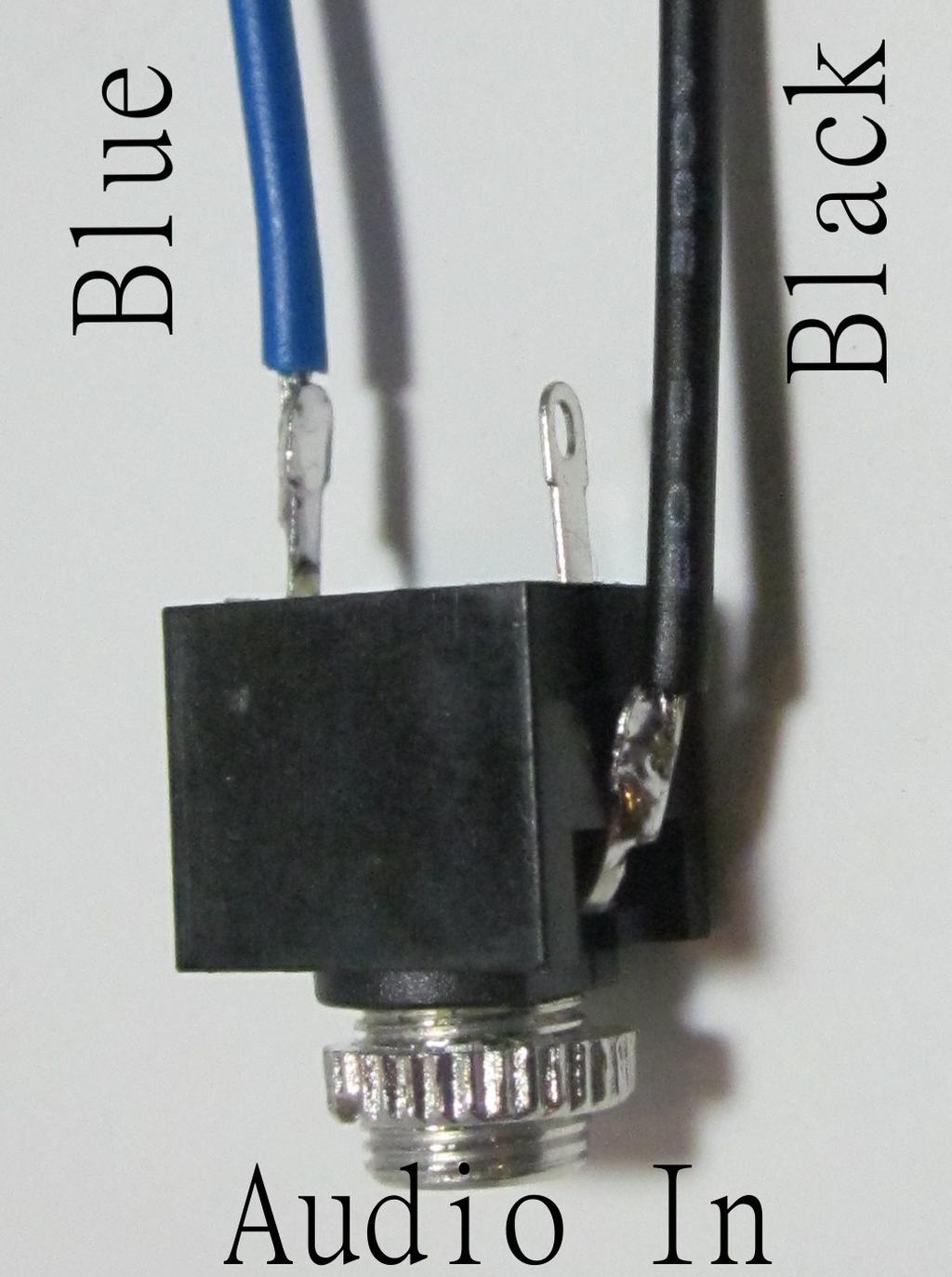
12 Chassis Jacks, plugs, and switch preparation 9. Wire Preparation ( ) Cut 3 pieces of black wire to 3" length. Strip 1/8" on one end and 1/4" on the other end. Lightly tin each end. ( ) For the Red, Blue, and White wires strip 1/8" on one end and 1/4" on the other end. Lightly tin each end. ( ) On the Ribbon cable peel off the last 3 wires OPPOSITE the black wire, these 3 are not needed. Peel each wire approximately 1" (25mm) down on both ends of the rubbon cable. Strip 1/8" (3mm) off each end and lightly tin. 10. Power jack: ( ) Solder the tinned 1/8" end of the red wire to the positive lead of the 2.1mm chassis power jack. The positive lead is at a right angle to the other 2 pins. ( ) Solder the tinned 1/8" end of a black wire to the negative lead of the 2.1mm chassis power jack. The negative lead is the opposite pin on the back of the jack. The center pin is not used. ( ) On the free ends of the red and black wire, strip 1/4" and tin. ( ) A 2.1mm plug is supplied for connection to your power source. Connect the tip (center pin) to the positive power source lead and the shield to the negative. When requested in future steps connect the free ends of the power jack to terminal block P107, Red to + and Black to -. Use the small screws at the top of the terminal block to secure the wires in place. The supplied 2.1mm plug can be used to connect into the jack. Do not connect the power jack at this time. 11. Audio input jack: Tip: Connect the mono jack into the plug and use an ohm meter to help find the tip and shield connections. ( ) Solder the tinned 1/8" end of a black wire to the SHIELD connection on the mono chassis jack. The Sheild connection is the one sticking out on the side. ( ) Solder the tinned 1/8" end of a blue wire to the TIP connection on a mono chassis jack. The tip connection is opposite the shield connection. The center connection is not used. ( ) On the free ends of the blue and black wire, strip 1/4" and tin. Notes: a) If desired you may gently bend the shield connector toward the back as seen in the photo. You may also trim the tip wire to match the black wire in length. b) A 3.5mm mono plug is supplied for connection to your radio. When requested in future steps connect the free ends of the mono jack to P101, Blue (tip) to + and Black (shield) to -. Use the small screws at the top of the terminal block to secure the wires in place. 6 Of 24
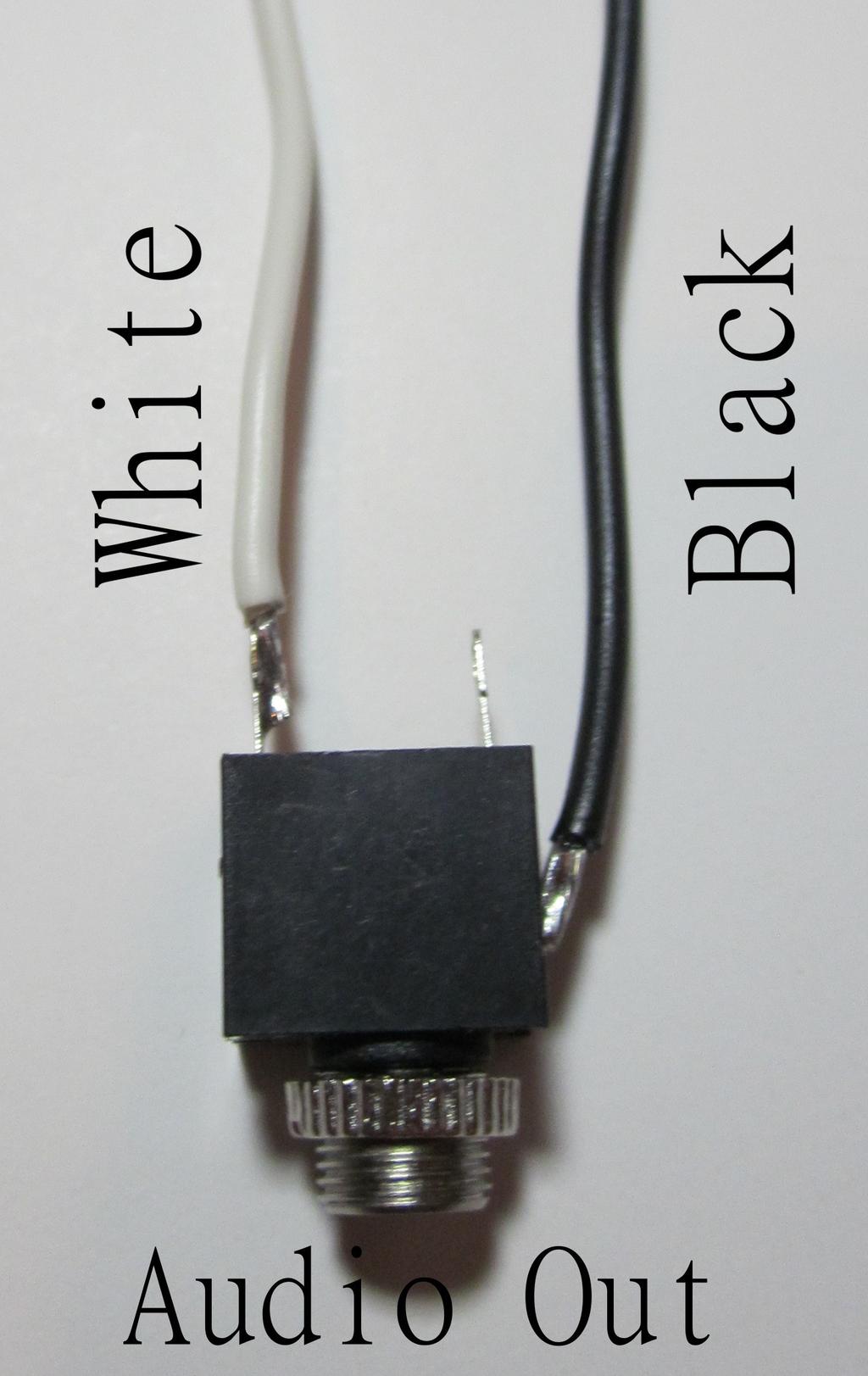
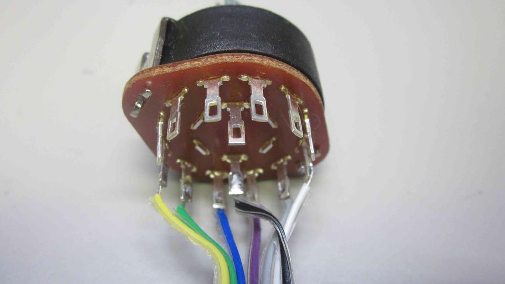
13 12. Audio output jack: ( ) Solder the tinned 1/8" end of a black wire to the SHIELD connection on the mono chassis jack. The Sheild connection is the one sticking out on the side. ( ) Solder the tinned 1/8" end of a white wire to the TIP connection on a mono chassis jack. The tip connection is opposite the shield connection. The center connection is not used. ( ) On the free ends of the white and black wire, strip 1/4" and tin. Notes: a) If desired you may gently bend the shield connector toward the back as seen in the photo. You may also trim the yellow tip wire to match the black wire in length b) A 3.5mm mono plug is supplied for connection to your speaker or headphones. When requested in future steps connect the free ends of the mono jack to P102, White (tip) to + and Black (shield) to -. Use the small screws at the top of the terminal block to secure the wires in place. 13. Rotary Switch Use the switch diagram below to locate the switch lug positions. Using the ribbon cable, solder the tinned 1/8" end of each wire to the terminal listed below: TIP: to find the correct terminals on the switch place the switch fully counterclockwise position then use an ohm meter to confirm the center and switch position 1. ( ) black wire to the B terminal ( ) blue wire to the B3 terminal ( ) white wire to the B6 terminal ( ) green wire to the B2 terminal ( ) grey wire to the B5 terminal ( ) yellow wire to the B1 terminal ( ) violet wire to the B4 terminal Note: The "A" portion of the switch is available for your own modifications. 7 Of 24


14 a) 8 Of 24
15 Main Board Assembly (Power Supply) 14. Install the following components: ( ) P pin right angle female header ( ) P107 2 pin terminal block Note: position the terminal block so the wire entrances are away from the board. ( ) D101 1N4007 diode "Black" Diode. Match the band on the diode to the silkscreen. ( ) R102 22K 1% Resistor Red-Red-Black-Red-Brown ( ) R103 22K 1% Resistor Red-Red-Black-Red-Brown ( ) C uF electrolytic capacitors ( ) C uF electrolytic capacitor Check polarity when installing. Check polarity when installing. ( ) C107 10uF electrolytic capacitor ( ) C108 10uF electrolytic capacitor Check polarity when installing. Check polarity when installing. ( ) U101 78L09 regulator IC 9 Of 24
16 15. Power Supply Testing: TIP: The terminal blocks are shipped with the screws fully tightened. You will need to loosen the screws in order to place the wires into the terminal block holes. Then snug the screws down to keep the wires in. ( ) Connect the front panel P1 to the main board P105. ( ) Connect the power jack to P107 as shown in the chassis jack preparation step. ( ) Using a DMM check the resistance across P107 with SW1 in both the ON AND OFF positions. There should be infinite resistance in the OFF position and a very high resistance, >100K to infinit ohms in the ON position. ( ) Connect your 12-15V power source to the power jack. ( ) Press SW1 to turn the power on. The Green ON LED should be lit. ( ) With a DMM measure the voltage at the following places using ground as the reference: ( ) 9V at pin 4 of U201 ( ) 4.5V at pin 3 of U201 ( ) Measure your power supply voltage at P107: ( ) Measure the voltage at pin 6 of U301. This should be about.6v less than the power supply voltage at P107. ( ) Switch off SW1, Disconnect the power and the power jack, and separate the front panel from the main PCB. TIP: Loosen the screws from the terminal blocks and remove the wires. Once removed snug the screws back down so they do not fall out. Main Board Assembly (Audio Amplifier) 16. Install the following components: ( ) R K ohm 1% resistor ( ) R301 10K ohm 1% resistor ( ) R ohm resistor ( ) C uF (47nF) ceramic capacitor ( ) C uF (47nF) ceramic capacitor 10 Of 24 Brown-Black-Black-Orange-Brown Brown-Black-Black-Red-Brown Brown-Black-Black-Gold ( ) C uF electrolytic capacitor ( ) C uF electrolytic capacitor Note Polarity Note Polarity ( ) C101 10uF electrolytic capacitor ( ) C305 10uF electrolytic capacitor Note Polarity Note Polarity ( ) U301 8 pin IC Socket Align notch on socket to notch on silkscreen
17 ( ) press LM386 IC into socket U301 ( ) P106 ( ) P102 2 pin right angle female header 2 pin terminal block ( ) Pin A 1 pin header 11 Of 24 Align the notch of the IC to the notch on the socket. Some IC's do not have a notch. In this case the dot represents pin 1. Align the dot to the square pad on the PCB. You may need to slightly bend the legs to fit it in the socket. Note: position the terminal block so the wire entrances are away from the board. Optional, for experimenting
 ceramic capacitor 104 ( ) D203 1N4148 diode \"Small Glass\" Diode.")
18 Main Board Assembly LED Detector/Driver 17. Install the following components: ( ) C103.01uF (10nF) ceramic capacitor 103 ( ) C202.1uF (100nF) ceramic capacitor 104 ( ) D203 1N4148 diode "Small Glass" Diode. Observe band ( ) R205 2K ohm 1% resistor ( ) R K Resistor ( ) R210 10K ohm 1% resistor Red-Black-Black-Brown-Brown Red-Red-Yellow-Gold Brown-Black-Black-Red-Brown ( ) R K ohm resistor ( ) R K ohm resistor ( ) R K ohm resistor Yellow-Violet-Red-Gold Brown-Grey-Red-Gold Brown-Red-Red-Gold ( ) R K ohm resistor ( ) R209 15K ohm resistor ( ) R207 1K ohm resistor Brown-Grey-Red-Gold Brown-Green-Orange-Gold Brown-Black-Red-Gold ( ) U202 ( ) U Of pin IC socket Align notch on socket to notch on silkscreen Align notch on IC to notch on socket LM324 IC
19 Main Board Assembly Input Buffer Amp / Limiter 18. Install the following components: ( ) R202 1K ohm resistor Brown-Black-Red-Gold ( ) D202 1N4148 diode "Small Glass" Diode Observe polarity of bands! ( ) D201 1N4148 diode "Small Glass" Diode Observe polarity of bands! Hint: D201 is installed in reverse of D202. ( ) R204 ( ) R203 ( ) R201 1K ohm resistor 10K ohm 1% resistor 2K ohm 1% resistor Brown-Black-Red-Gold Brown-Black-Black-Red-Brown Red-Black-Black-Brown-Brown ( ) R01 ( ) C K ohm trimmer.47uf (470nF) Mylar capacitor ( ) C104 ( ) C105.01uF (10nF) ceramic capacitor.01uf (10nF) ceramic capacitor ( ) U pin IC socket ( ) U401 ( ) U201 ( ) U401 ( ) P pin IC socket TL084 IC TL084 IC 2 pin Terminal block Align notch on socket to notch on silkscreen See U201 above Align notch on IC to notch on socket See U201 above Note: position the terminal block so the wire entrances are away from the board. ( ) Install the following 2 pin headers: JP201, JP202, JP401, JP402, JP403, JP404, JP405 These may be installed individually or in groups. For example JP201, JP202, and JP401 may be installed as a 6 pin header. Header pins may be shipped together in a breakaway configuration. ( ) Install a 2 pin shorting block over each of the above jumpers. NOTE: The audio limiter/filter will not operate correctly without the jumpers installed. ( ) Install the 4 pin header at P113 (optional) ( ) Install the single pin headers at BUF and F3 (optional) 13 Of 24
20 19. Buffer, Limiter, LED, and Amplifier testing: ( ) Connect the front panel P101 to the main board J101. ( ) With a DMM measure across the Audio Input contacts (P101). This should be approximately 10K. ( ) Connect the power jack to P104 as shown in the chassis jack preparation step. ( ) Connect the audio input jack to P101 as shown in the chassis jack preparation step. ( ) Connect the audio output jack to P102 as shown in the chassis jack preparation step. ( ) Connect a speaker or headphones to the audio output jack/plug. ( ) Connect a receiver or audio signal generator to the audio input jack/plug. Optimally a signal generator set to 700Hz sine wave at 500mV along with an oscilloscope can be used, however, a receiver set to a constant tone or AM station such as WWV can also be used for this test. ( ) Set the INPUT and VOLUME controls on the front panel fully couter clockwise. ( ) Set RV1 to mid-position. ( ) Connect your 12-15V power source to the power jack/plug. ( ) Press SW1 to turn the power on. The Green ON LED should be lit. ( ) Turn the "INPUT" limit potentiometer, The OK, LIMIT, and OVLD LED's should each come on as the potentiometer is turned toward maximum. If the unit is too sensitive (All LED's come on with little turning of the INPUT potentiometer, turn R01 counter14 Of 24
21 clockwise to reduce the sensitivity. If all of the LED's are not on when the INPUT potentiometer is fully clockwise then turn R01 clockwise until all LED's are on. Oscilloscope and generator testing You can observe the limiter in action by placing a test probe on the AUDIO IN connection and a second probe on SW101 pin #1. As the LIMIT potentiometer is adjusted you should see the following at SW101-1: Green LED turns on with a 400mVp-p signal. Yellow LED turns on with a 1Vp-p signal with slightly flattened peak. Red LED turns on a 1.2Vp-p signal with an almost square shape. As the limiter is turned past the Red LED setting, the wave will become more square with a maximum amplitude of about 1.25Vp-p. ( ) Using a small piece of scrap wire, carefully and temporairly jumper (do not solder!) SW101 from points C to 1. You should be able to hear the signal when turning the volume potentiometer up. Remove the jumper. ( ) Switch off SW1, Disconnect the power and the power jack along with the audio input and output jacks, and separate the front panel from the main PCB. Main Board Assembly Filter Stages 20. DECISION: To experiment or not? If you wish to use the filter with the provided R/C values and not make experimental changes, please skip this step and proceed to the installing the R/C values section to solder the filter components dorectly onto the board. A set of male and female headers along with PCB's (CALF ears) are included to allow changing the 6 different filter sections. The following technique is an easy way to match up the headers for good alignment. ( ) Create 5 pin headers from the break away strip of headers. ( ) Mate 2 sections of 5 pin male headers into each 10 pin female header. Make sure the long ends of the headers are inside the female sockets. ( ) Place the female socket side of the mated pair into the socket areas on the main PCB. ( ) Apply 2 of the CALF Ears PCB's on top of each pair of the male header pins. Note the silkscreen on the bottom of the PCB to show the header pin locations. Also make sure the Ears PCB's are oriented to point away from the IC, they should not overlap it. ( ) Once you are happy with the positioning solder the Ears down onto the headers. ( ) Then solder the female headers onto the main PCB. The assembly will help keep the headers aligned between the 2 boards. 15 Of 24


 as trimming the leads between the headers may be tricky.")
22 ( ) With the ears in place you can individually remove the PCB's as needed to install the resistor and capacitor values for each section below. A few tips for matching and soldering: For each section in the steps below match the "N" numbers to the value needed. Keeping the Ears PCB into the socket while matching up the values. Soldering from the top side may be easier than between the header rows on the bottom. Pre-trim the leads (but not too short!) as trimming the leads between the headers may be tricky. Install the resistors vertically. These little boards can be crowded. Take your time. A small bench vise can also help hold the boards while soldering. 16 Of 24
23 21. Install the following components R/C Values section 1 and 2: (Hint use a meter to mearure the 1% resistors some color bands like red and orange can appear to be the same as well as the order of the bands -left to right or right to left can appear to be a value which isn't). Section 1 ( ) N1 R404 22K 1% resistor Red-Red-Black-Red-Brown ( ) N2 C404 10nF.01uF 5% mylar capacitor 103 Use the 2 holes closest to the IC ( ) N3 C401 10nF.01uF 5% mylar capacitor 103 Use the 2 holes closest to the IC ( ) N4 R401 47K 1% resistor Yellow-Violet-Black-Red-Brown ( ) N5 R407 22K 1% resistor Red-Red-Black-Red-Brown Section 2 ( ) N5 R408 ( ) N4 R402 ( ) N3 C402 ( ) N2 C405 ( ) N1 R405 10K 1% resistor 68K 1% resistor 10nF.01uF 5% mylar capacitor 10nF.01uF 5% mylar capacitor 33K 1% resistor Brown-Black-Black-Red-Brown Blue-Grey-Black-Red-Brown 103 Use the 2 holes closest to the IC 103 Use the 2 holes closest to the IC Orange-Orange-Black-Red-Brown 22. Install the following components R/C Values section 3 and 4: 17 Of 24
24 Section 4 ( ) N1 R413 ( ) N2 C410 ( ) N3 C407 ( ) N4 R410 ( ) N5 R416 27K 1% resistor 22nF.022uF 5% mylar capacitor 22nF.022uF 5% mylar capacitor 56K 1% resistor 2K 1% resistor Red-Violet-Black-Red-Brown 223 Use the first and last holes 223 Use the first and last holes Green-Blue-Black-Red-Brown Red-Black-Black-Brown-Brown Section 3 ( ) N5 R409 ( ) N4 R403 ( ) N3 C403 ( ) N2 C406 ( ) N1 R K 1% resistor 100K 1% resistor 10nF.01uF 5% mylar capacitor 10nF.01uF 5% mylar capacitor 47K 1% resistor Green-Blue-Black-Brown-Brown Brown-Black-Black-Orange-Brown 103 Use the 2 holes closest to the IC 103 Use the 2 holes closest to the IC Yellow-Violet-Black-Red-Brown 18 Of 24
25 23. Install the following components R/C Values section 5 and 6: Section 5 ( ) N1 R414 43K 1% resistor Yellow-Orange-Black-Red-Brown ( ) N2 C411 22nF.022uF 5% mylar capacitor 223 Use the first and last holes ( ) N3 C408 22nF.022uF 5% mylar capacitor 223 Use the first and last holes ( ) N4 R411 82K 1% resistor Grey-Red-Black-Red-Brown ( ) N5 R K 1% resistor Brown-Orange-Black-Brown-Brown Section 6 ( ) N5 R418 ( ) N4 R412 ( ) N3 C409 ( ) N2 C412 ( ) N1 R Of ohm 1% resistor 120K 1% resistor 22nF.022uF 5% mylar capacitor 22nF.022uF 5% mylar capacitor 56K 1% resistor White-Brown-Black-Black-Brown Brown-Red-Black-Orange-Brown 223 Use the first and last holes 223 Use the first and last holes Green-Blue-Black-Red-Brown
26 Main Board Assembly (Final Assembly) 24. Rotary Switch installation & Final Assembly ( ) Slide the rotary switch into the front panel making sure the alignment pin on the switch is properly inserted into the alignment hole on the panel. Secure with the supplied washer and nut. Rotate the switch the the fully counter clockwise position and insert the switch knob so the alignment mark is in the L position. ( ) Mate the front panel to the main PCB and secure the main PCB to both L brackets using a 4-40 screw. ( ) Route the ribbon cable toward the back of the main PCB labeled as SW101 and solder each lead of the ribbon into the following positions: 1 Yellow 5 Grey 2 Green 6 White 3 Blue C Black 4 Violet ( ) Insert a 4-40 screw through the bottom of the enclosure using one of the two inside holes (the outside holes are to secure the top). Do the same with the other hole. Flip the enclosure right side up on the table keeping the screws in place. Slip a 1/4" spacer over each 4-40 screw. Slide the CALF assembly into the enclosure by aligning the front panel with the slots and 2 screws with spacers on the rear mounting holes. Secure with a #4 lock washer and nut. ( ) Attach the Audio in, Audio out, and Power jack assemblies to the rear enclosure panel using the nuts provided. Connect the wires from these 3 assemblies to the terminal blocks on the main board as discussed in proir testing instructions. Slide the rear panel into the rear enclosure slots. ( ) Slide the top enclosure onto the bottom and secure with the 2 supplied screws. Attach feet to bottom of enclosure Congradulations! Your audio limiter/filter is now ready to use! 20 Of 24
27 Operation: ( ) Adjust front panel INPUT and VOLUME potentiometers to fully counter-clockwise. ( ) Connect power, radio (or audio input), and speaker/headphones. Note: CALF uses MONO jacks. Some modern equipment uses STEREO jacks. A stereo to mono adapter may be required for proper operation. ( ) Place the front panel rotary switch in the L(limit) position. ( ) Power the unit on. ( ) Initial Adjustment Specific to your selected radio. ( ) Turn the radio on and tune to a station. Keep the volume on the radio to a low level to prevent overload. A voice station (such as WWV) works the best for this adjustment but even a CW signal will work. ( ) Set the audio INPUT potentiometer on the front panel to mid-position. Adjust the audio output VOLUME potentiometer to a comfortable level. ( ) Adjust the buffer amp trimmer RV101 until the green LED lights fully and the yellow LED barely flashes. In most cases RV101 will be fine in the center position and the radio volume control can be used to make this adjustment. However, some commercial radios may supply too much volume or QRP equipment too little, in these cases RV101 may be used to amplify or attenuate the signal. ( ) Regular operation - Adjust the audio INPUT pot until the green LED is lit and the yellow led barely flashes. Weak Signal Tip You may find a weak, barely audible, signal slightly better to receive by increasing the audio INPUT until RED flashes a little. This will sound noisey, but weak signals can be copied better. The Filter Section will pull out the 700 CW signal! ( ) Adjust the audio output VOLUME control to a comfortable listening level. NEVER make your signal too loud for your ears!! ( ) Select the various filter settings on the rotary switch as desired. Experimenting with Filters This board has been designed for experimenting with different types of inverting multiple feedback active filters when IC sockets are used in the filter R/C values area. Schematics for Low, High, and Bandpass filter examples are shown in the appendix of this manual. ( ) Choose the type of filter High, Low, or Band pass ( ) Calculate your R/C values Highly recommended are the ARRL handbook and TI's FilterPro software. Note: The ARRL handbook uses NON-inverting low and high pass filter examples which use different calculations. However, the Band-pass filter is inverting. Better models can be found at and ( ) Place your R/C values into the desired filter section using the "N1-5" values shown in the the example schematic. For example if you wish to place a 1KHz low pass filter in the first section: N1 10K resistor (R404) N2 5.6K resistor (C404) N3 10K resistor (C401) 21 Of 24
28 N4 10nF.01uF capacitor N5 27nF.027uF capacitor (R401) (R407) The filters can also be re-arranged or other circuitry may be added in between the stages using the following jumper blocks: Jumper Pin 1 (Square) Pin 2 (Oval) JP201 Input to Limiter Output from Buffer Amp JP202 Output from Limiter Input to Filter #1 JP401 Output from Filter #1 Input to Filter #2 JP402 Output from Filter #2 Input to Filter #3 JP403 Output from Filter #3 Input to Filter #4 JP404 Output from Filter #4 Input to Filter #5 JP405 Output from Filter #5 Input to Filter #6 There are 2 additional solder pads, BUF and F3 which can be used as additional switch positions. BUF is from the output of the audio input buffer OP AMP. F3 is from the 3rd filter section output. Circuit Description: Power Supply 11-15V is applied to the power jack at P107. U101 provides 9V output to power the filter Op Amp IC's. R102 and R103 create a voltage divider to provide 4.5V to the non-inverting pins of the filter Op Amp sections. The capacitors in the power supply section are used mainly for A/C bypass. Buffer Amp Audio input is fed into C201 (a DC blocking capacitor) and then into the input limiter volume control RV1 on the front panel which then feeds into an inverting OP AMP at U201A. R01 provides an internal gain/attenuation adjustment so that a wide variety of audio input ranges can be used. Limiter Audio from the buffer amp is fed into the second section of the TL084 OP AMP and limited to approximately 1.2Vp-p. This normally suppresses, but does not eliminate, a large static crash, such as from lightening. This in turn brings the loud "crash" to the same volume level as a weaker signal. This limiter is an "instant acting" type. Very simple and very effective. During Limiting Action, the energy of the "crash" is integrated instantly into the baseband noise level as sub / supra harmonics, creating a momentary muffled sound. Operating: 22 Of 24
29 (1) When a "Weak" Signal is being worked, then the Audio-Input can be turned up to force Limiting Action, and the Audio-Output turned down to match. The background noise level is increased but the Filter section will pull out the 700 Hz CW nicely. (2) When a "Normal" signal is being worked, then the Audio-Input can be turned down to squelch Limiting Action and the Audio-Output turned up to match. Detector & LED driver Audio from the buffer amplifier is also tapped off and fed to the input of an LM324 OP AMP at U202A running as a regular inverting amplifier with a gain of 2. The output is then rectified with Diode D203 and filtered to a slow moving DC value using R208 and C202. R209 and R210 form a 3.4V voltage divider to properly bias U202A so that 0VDC is produced at the output of D203 when no input signal is present. The slower moving DC is then fed into the remaining 3 sections of the LM324 which are used as voltage comparators. Each section is offset biased using a voltage divider consisting of R206, R211, R212, and R213. Each LED will turn on as the incoming DC value becomes larger than the divider voltage as follows: Audio IN JP201 DC input U202-6,9,13 Divider LED Status 0 0 N/A All LEDs OFF 375mVp-p > 1.66V U V Green ON (Good audio Signal Range) 1.6Vp-p > 2.75V U V Yellow ON (Audio signal limited) 3.4Vp-p > 4.50V U V RED ON (Audio signal overloading OP AMPs) Band Pass Filters There are 6 multiple-feedback band pass filters comprise the remaining 2 sections of U201 as well as all of U401. Each filter section is designed near the center frequency of 700Hz and cascades into the next. The 6 position rotary switch allows selection of 5 points through the filter process ranging from a bandwith of 700Hz down to less than 100Hz. Typical filters settings are as follows: Switch 3dB Width db / Octave 23 Of 24 L None None F1 700Hz 5dB F2 350Hz 13dB F3 175Hz 35dB F4 125Hz 41dB
30 F5 <100Hz 41dB Audio Amplifier Audio is fed from the rotary switch to C101, a DC blocking capacitor, and R101 to attenuate the incoming voltage level. The signal is then fed to R on the front panel for volume control and into an LM386 audio amplifier IC. R301 and C302 provide additional bass boost. The output of the audio amplifier is sent to C303, a DC blocking capacitor, which in turn drives a small speaker of headphones. Need a little extra volume? R101 can be reduced down to 22K (not included with kit) which will supply extra volume to an external speaker. You will find the volume control to be more sensitive as R101 is decreased. It is recommended to keep R101 larger than 22K to avoid over driving the LM386 amplifier. Current Ratings: Supply Voltage Min Current (idle) Current full volume with speaker Current - full volume with speaker (w/ R101 modification) 24 Of VDC (11-15V) 32mA 70mA 175mA
31
32
33 A A SW1A nc c 1 3 no 2 DPDT-8X8MM +12V R1 2K2 D mm Green B +12R +12SW AFIn LimPot AFOut SPKR Good-LED Limit-LED OVLD-LED GND 10p Male P mm Green 2 1 D2 3mm Yellow 2 1 D3 R2 2K2 R3 2K2 +12V Var 2 CW CCW B 1 2p Male P2 2 CCW 1 Var 2 CW K RV1 1 SW1B nc 6 c no 4 5 DPDT-8X8MM 3mm Red 2 1 D4 R4 2K2 R 10K Volume C P103 Mounting Holes P104 P105 P106 C jwc kc9on File: CALF-Front.sch Sheet: / Title: CALF Front Panel Size: USLetter Date: 20 dec 2014 KiCad E.D.A. 4 5 Rev: 2 Id: 1/1
34
35
36
37
38
39
Read This Page First
 Read This Page First If you are reading this you know the manuals are always available at QRPKITS.com. This is version 8.0 of the manual dated 4/27/2016. There is no need to print out the whole assembly
HW-8-TR V3 PARTS LIST
 HW-8-TR V3 PARTS LIST Qty Ref Description Markings 4C2 C3 C4 C5 Capacitor Disc.1ls.1uF 104 1 C1 Capacitor Disc.2ls.1uF 100V 104 1 QSKMOD-C92 Capacitor Electrolytic 1uF 50V 1 QSKMOD Capacitor Mylar.47uF
Foxhunt Offset Attenuator. Parts List:
 When your closing in on the fox you may find the signals to be so strong that you can no longer find a peak or null with your antenna. Sometimes the signal is so strong that the RF will leak straight into
Building the Toothpick Audio CW Filter
 Building the Toothpick Audio CW Filter Introduction The toothpick is a simple variable bandpass audio filter designed to compliment the Splinter QRPp Trans-Receiver. The filter also contains an audio amplifier
Building the Sawdust Regenerative Receiver
 Building the Sawdust Regenerative Receiver Introduction The Sawdust is a super regenerative receiver using the basic Armstrong design architecture. The receiver uses one toroidal transformer to provide
CW-ADD. Universal CW Adapter for SSB Transceivers. Assembly manual. Last updated: October 1,
 CW-ADD Universal CW Adapter for SSB Transceivers Assembly manual Last updated: October 1, 2017 ea3gcy@gmail.com Updates and news at: www.ea3gcy.com Thanks for building the Universal CW Adapter kit CW-ADD
Building the Sawdust Regenerative Receiver
 Building the Sawdust Regenerative Receiver Introduction The Sawdust is a super regenerative receiver using the basic Armstrong design architecture. The receiver uses one toroidal transformer to provide
Polyphase network kit
 Polyphase network kit 1. Introduction This polyphase network module is designed to be used with the QRP Labs receiver module kit. It takes as inputs, four phase audio from the Quadrature Sampling Detector
Wiring Manual NEScaf April 2010 (August 2006)
") Wiring Manual NEScaf April 2010 (August 2006) Switched Capacitor Audio Filter The NEScaf is a switched capacitor audio filter (acronym SCAF) built around a building-block type filter chip. The NEScaf will
Wiring Manual NEScaf April 2010 (August 2006) Switched Capacitor Audio Filter The NEScaf is a switched capacitor audio filter (acronym SCAF) built around a building-block type filter chip. The NEScaf will
ABC V1.0 ASSEMBLY IMPORTANT!
 ABC V1.0 ASSEMBLY Before starting this kit, prepare the following tools: Soldering iron (15-20W will do), flush cutters, no.2 hex screwdriver or allen key and phillips screwdriver. Also briefly go through
Value Location Qty Potentiometers C1M Distortion 1 A10k Volume 1. Footswitch 3PDT SW1 1. Jacks 1/4 Mono 2 DC Power 1
 Distortion BUILD INSTRUCTIONS Thank you for your purchase of our Distortion+ kit! We have completely redesigned our entire line of kits to be the most user friendly, while still maintaining their same
Bill of Materials: PWM Stepper Motor Driver PART NO
 PWM Stepper Motor Driver PART NO. 2183816 Control a stepper motor using this circuit and a servo PWM signal from an R/C controller, arduino, or microcontroller. Onboard circuitry limits winding current,
Value Location Qty Transistors 2N5485 Q1, Q2, 4 Q3, Q4 2N5087 Q5 1. Trim Pots 250k VTRIM 1. Potentiometers C500k Speed 1. Toggle Switch On/On Vibe 1
 P-90 BUILD INSTRUCTIONS Thank you for your purchase of our P-90 kit! We have completely redesigned our entire line of kits to be the most user friendly, while still maintaining their same great sound!
S-Pixie QRP Kit. Student Manual. Revision V 1-0
 S-Pixie QRP Kit Student Manual Revision V 1-0 Introduction The Pixie 2 is a small, versatile radio transceiver that is very popular with QRP (low power) amateur radio operators the world over. It reflects
Penrose Quantizer Assembly Guide
 Penrose Quantizer Assembly Guide Schematic and BOM The schematic can be found here: www.sonic-potions.com/public/penrosequantizerschematic.pdf The BOM is available at google docs: Link to BOM Prepare the
The ability to make basic voltage and resistance measurements using a digital multimeter
 Congratulations on your purchase of a new OneShot chassis! The PC01 OneShot combines a rugged enclosure, power supply, and discrete instrument DI in a compact 1/4U package. A few minutes of assembly are
DIODE / TRANSISTOR TESTER KIT
 DIODE / TRANSISTOR TESTER KIT MODEL DT-100K Assembly and Instruction Manual Elenco Electronics, Inc. Copyright 1988 Elenco Electronics, Inc. Revised 2002 REV-K 753110 DT-100 PARTS LIST If you are a student,
FMR622S DUAL NARROW BAND SLIDING DE-EMPHASIS DEMODULATOR INSTRUCTION BOOK IB
 FMR622S DUAL NARROW BAND SLIDING DE-EMPHASIS DEMODULATOR INSTRUCTION BOOK IB 1222-22 TABLE OF CONTENTS SECTION 1.0 INTRODUCTION 2.0 INSTALLATION & OPERATING INSTRUCTIONS 3.0 SPECIFICATIONS 4.0 FUNCTIONAL
Assembly Manual V1R2B-Rev1.0D
 Assembly Manual V1R2B-Rev1.0D for 4 State QRP MagicBox - Solid State Transmit/Receive System Designed by: Jim Kortge, K8IQY Copyright 2009-2012 - All rights reserved This system is the result of some brainstorming
Cricket 80a Assembly Manual v Copyright David Cripe NM0S The 4 State QRP Group
 Cricket 80a Assembly Manual v. 1.0 Copyright 2017 David Cripe NM0S The 4 State QRP Group Introduction Thank you for purchasing a CRICKET 80a Transceiver. We hope you will enjoy building it and find it
Mono Amplifier. LM386 Headphone Amp
 Mono Amplifier LM386 Headphone Amp Layout On/Off Switch - cuts power to the circuit Mono Input Jack: use either L or R or solder together Schematic Step 1 - Parts List 1.) R1-10ohm Resistor - Brown Black
Pacific Antenna Easy Transmitter Kit
 Pacific Antenna Easy Transmitter Kit Introduction The Easy Transmitter kit from qrpkits.com provides a crystal controlled transmitter with VXO tuning. The circuit consists of a N3904 based crystal oscillator
FM Audio/Squelch Board by Steve Dold, W6KCS w6kcs (at) stevedold (dot) com
 stevedold (dot) com") FM Audio/Squelch Board by Steve Dold, W6KCS w6kcs at stevedold dot com Board hardware version 7-8 Firmware version 7.x This board connects to an FM receiver's discriminator/detector and provides squelched,
FM Audio/Squelch Board by Steve Dold, W6KCS w6kcs at stevedold dot com Board hardware version 7-8 Firmware version 7.x This board connects to an FM receiver's discriminator/detector and provides squelched,
Building and Operating: Son of Zerobeat A PIC based CW zerobeat indicator from Jackson Harbor Press
 Building and Operating: Son of Zerobeat A PIC based CW zerobeat indicator from Jackson Harbor Press Ed Nisley, KE4ZNU, wrote an article published in the August, September and October of 1996 issues of
FUNCTION GENERATOR KIT
 FUNCTION GENERATOR KIT MODEL FG-500K Assembly and Instruction Manual Elenco Electronics, Inc. Copyright 2005 by Elenco Electronics, Inc. All rights reserved. Revised 2005 REV-B 753069 No part of this book
The Tellun Corporation. TLN-442 Voltage Controlled Lowpass Filter. User Guide, Rev Scott Juskiw The Tellun Corporation
 The Tellun Corporation TLN-442 Voltage Controlled Lowpass Filter User Guide, Rev. 1.1 Scott Juskiw The Tellun Corporation scott@tellun.com TLN-442 User Guide Revision 1.1 March 15, 2003 Introduction The
Enhancing Your QRP Operating Enjoyment
 QRP-DWM Directional-Coupler Watt Meter Preliminary By: W5USJ CyM-Tech Documentation Services Enhancing Your QRP Operating Enjoyment PCB Assembly Top View Addendum: Correct missing toroid ground after installing
Pacific Antenna Field Strength Indicator Kit
 Pacific Antenna Field Strength Indicator Kit Description The Field Strength Indicator kit from Pacific Antenna provides a visual way to monitor the presence and relative strength RF fields through the
Manual Version July 2007
 Manual Version 1.2 - July 2007 Page 1 Table of Contents Section1: M3 Phono Board Build...3 Phono Board Parts List...3 Preparation...4 Fitting the Valve Bases...6 Installing the Resistors...7 Starting the
Starving Student II. Starving Student II. SS2 guide. Written By: 6L guides.diyaudio.com/ Page 1 of 24
 SS2 guide Written By: 6L6 2019 guides.diyaudio.com/ Page 1 of 24 INTRODUCTION This is a build guide for the hybrid headphone/pre-amplifier. You can buy a kit at the SSII product listing on the diyaudio
The Walford Electronics Ford Receiver Kit Project Construction Manual
 The Walford Electronics Ford Receiver Kit Project Construction Manual Walford Electronics Ford Receiver construction manual V1.5 Page 1 of 22 Introduction The Ford receiver has four stages: The first stage
LITTLE NERD v1.1 Assembly Guide
 last update: 9. 3. 2016 LITTLE NERD v1.1 Assembly Guide bastl instruments.com INTRODUCTION This guide is for building Little Nerd module from Bastl Instruments. It is good to have basic soldering skills
Pingable Envelope Generator
 Pingable Envelope Generator Kit Builder's Guide for PCB v1.0.3 4mspedals.com PEG This guide is for building a Pingable Envelope Generator (PEG), which is an intermediate-level kit. You should be confident
LA502 Assembly guide Main PCB Resistors - (2)
") LA502 Assembly guide Safety warning The kits are main powered and use potentially lethal voltages. Under no circumstance should someone undertake the realisation of a kit unless he has full knowledge about
LA502 Assembly guide Safety warning The kits are main powered and use potentially lethal voltages. Under no circumstance should someone undertake the realisation of a kit unless he has full knowledge about
Find a place where you can work through completion, without disturbing your
 Scan by Manual Manor ARIES SYSTEM 300 MUSIC SYNTHESIZER Page I of 4 MODULE AR-334 SEQUENCER ASSEMBLY INSTRUCTIONS It is recommended that you do the following before you proceed: Find a place where you
MP573 Assembly guide. Soldering. MP573 Assembly guide PCB split PCB split. Document revision 2.2 Last modification : 22/08/17
 MP573 Assembly guide Safety warning The kits are main powered and use potentially lethal voltages. Under no circumstance should someone undertake the realisation of a kit unless he has full knowledge about
Ten Tec DDS Board Assembly Procedure
 05 May 2014 Ten Tec DDS Board Assembly Procedure You will find a photo of a completed board at the end of these instructions. Refer it whenever clarification is required. 1. AD9835 Attachment If you purchased
TLN-428 Voltage Controlled State Variable Filter
 The Tellun Corporation TLN-428 Voltage Controlled State Variable Filter User Guide, Rev. 1.1 Scott Juskiw The Tellun Corporation scott@tellun.com TLN-428 User Guide Revision 1.1 March 16, 2003 Introduction
TS500 Assembly guide. Soldering. TS500 Assembly guide Main PCB 1. Diodes. Document revision 1.2 Last modification : 17/12/16
 TS500 Assembly guide Safety warning The kits are main powered and use potentially lethal voltages. Under no circumstance should someone undertake the realisation of a kit unless he has full knowledge about
DIODE / TRANSISTOR TESTER KIT
 DIODE / TRANSISTOR TESTER KIT MODEL DT-100K 99 Washington Street Melrose, MA 02176 Phone 781-665-1400 Toll Free 1-800-517-8431 Visit us at www.testequipmentdepot.com Assembly and Instruction Manual Elenco
IPR LA-3 KIT last update 15 march 06
 IPR LA-3 KIT last update 15 march 06 PART-2: Audio Circuitry CIRCUIT BOARD LAYOUT: Power and Ground Distribution Now that your power supply is functional, it s time to think about how that power will be
THE RING RESONATOR (K-975)
") THE RING RESONATOR (K-975) OUTPUT BOOST The Ring Resonator An Octave Up Fuzz Modkitsdiy.com 9 VDC CENTER (-) ADAPTER TO AMP IN FROM GUITAR OUT Unplug when not in use to save battery life. Use these instructions
THE RING RESONATOR (K-975) OUTPUT BOOST The Ring Resonator An Octave Up Fuzz Modkitsdiy.com 9 VDC CENTER (-) ADAPTER TO AMP IN FROM GUITAR OUT Unplug when not in use to save battery life. Use these instructions
Easy Transmitter. Support ETX_REV5_Manual V2.7 Revised
 Easy Transmitter Introduction The Easy Transmitter kit from qrpkits.com provides a basic, crystal controlled transmitter with VXO tuning to provide a small tuning range around the crystal frequency. It
QRPGuys Michigan Mighty Might Plus 40M Transmitter
 QRPGuys Michigan Mighty Might Plus 40M Transmitter First, familiarize yourself with the parts and check for all the components. If a part is missing, please contact us and we will send one. You must use
HT-1A Dual Band CW QRP Transceiver. Kit Building Instructions
 HT-A Dual Band CW QRP Transceiver Kit Building Instructions Rev B, July 8, 08 Designed by BD4RG Exclusively distributed by CRKITS.COM and its worldwide distributors Join the group http://groups.io/g/crkits
Balanced Modulator. Model 9748 Assembly and Using Manual PAiA Corporation
 Balanced Modulator Model 9748 Assembly and Using Manual This second-generation 9700-series processing element for modular sound synthesizers is designed to provide great sound and excellent value. Audio
SDR Cube Transceiver Online Assembly Guide
 SDR Cube Transceiver Online Assembly Guide Detailed construction notes for building and testing each of the SDR Cube kit modules Home Bill of Materials I/O Board Controls Board DSP Board Softrock SR-Base
INSTRUCTIONS FOR ASSEMBLY AND OPERATION
 diytube stereo 0 driver board INSTRUCTIONS FOR ASSEMBLY AND OPERATION Price $0.00 Important Note: The phase is swapped on the diytube ST0 from the orginal design. Be sure to hook up the drive lines (at
ALM473 DUAL MONO \ STEREO AUDIO LEVEL MASTER OPERATION MANUAL IB
 ALM473 DUAL MONO \ STEREO AUDIO LEVEL MASTER OPERATION MANUAL IB6408-01 TABLE OF CONTENTS GENERAL DESCRIPTION 2 INSTALLATION 2,3,4 CONNECTION AND SETUP 4,5,6,7 FUNCTIONAL DESCRIPTION 8,9 MAINTENANCE 9
LED S METER CONSTRUCTION MANUAL. LED S meter Construction Manual Issue 1.0 Page 1
 LED S METER CONSTRUCTION MANUAL LED S meter Construction Manual Issue 1.0 Page 1 Important Please read before starting assembly STATIC PRECAUTION The LED S Meter kit contains components which can be damaged
SpikerBox v1.3 DIY Instructions
 SpikerBox v. DIY Instructions Prepare yourself. In hours, you will have built your own SpikerBox to begin doing neuroscience and whatever your creative mind can conjure. Materials Needed:. A Backyard Brains
The Tellun Corporation. TLN-861 Dunsel. User Guide, Rev Scott Juskiw The Tellun Corporation
 The Tellun Corporation TLN-861 Dunsel User Guide, Rev. 1.0 Scott Juskiw The Tellun Corporation scott@tellun.com TLN-861 User Guide Revision 1.0 August 31, 2006 1. Introduction The TLN-861 Dunsel is a collection
LED Field Strength Indicator Kit
 LED Field Strength Indicator Kit Description The Field Strength Indicator kit from Qrpkits.com provides a visual way to monitor RF fields through the brightness of an LED. It will respond to RF fields
Pacific Antenna - Easy TR Switch
 Pacific Antenna - Easy TR Switch Kit Description The Easy TR Switch is an RF sensing switch that can be used to switch an antenna between a receiver and transmitter. It also has a second switched pair
Code Practice Oscillator (CPO) For kit building instructions turn to Page 3.
 For kit building instructions turn to Page 3.") Code Practice Oscillator (CPO) For kit building instructions turn to Page 3. Overview Many thanks for your purchase of this code practice oscillator or CPO, this guide is intended to allow you to quickly
Code Practice Oscillator (CPO) For kit building instructions turn to Page 3. Overview Many thanks for your purchase of this code practice oscillator or CPO, this guide is intended to allow you to quickly
Bill of Materials: Metronome Kit PART NO
 Metronome Kit PART NO. 2168325 The metronome kit allows you to build your own working electronic metronome. Features include a small speaker, flashing LED, and the ability to switch between several different
PM124 Installation Instructions. See important note about revisions of this board on the last page.
 Marchand Electronics Inc. PO Box 473, Webster, NY 14580 Tel:(716) 872-0980 Fax:(716) 872-1960 info@marchandelec.com http://www.marchandelec.com (c)1997 Marchand Electronics Inc. PM124 Installation Instructions
Specimen Products Single Ended Stereo Amp Instruction Book
 Specimen Products Single Ended Stereo Amp Instruction Book Specimen tube amplifier designs are informed by decades of servicing and building musical instrument amps. As a result of being subjected to the
the DON classics U76 (blue face - rev A) ASSEMBLY GUIDE REV: 1:04
 ASSEMBLY GUIDE REV: 1:04") the DON classics www.thedonclassics.com U76 (blue face - rev A) ASSEMBLY GUIDE REV: 1:04 QUICK ASSEMBLY GUIDE 9 STEPS TO COMPRESSOR HEAVEN! 1. 2. 3. 4. 5. 6. 7. 8. 9. Solder parts on PCB Wire pots Solder
the DON classics www.thedonclassics.com U76 (blue face - rev A) ASSEMBLY GUIDE REV: 1:04 QUICK ASSEMBLY GUIDE 9 STEPS TO COMPRESSOR HEAVEN! 1. 2. 3. 4. 5. 6. 7. 8. 9. Solder parts on PCB Wire pots Solder
Build Your Own Clone 27V Boost Kit Instructions
 Build Your Own Clone 27V Boost Kit Instructions Warranty: BYOC, Inc. guarantees that your kit will be complete and that all parts and components will arrive as described, functioning and free of defect.
12kHz LIF Converter V2.43 9Mhz version
 12kHz LIF Converter V2.43 9Mhz version Please Note: This document supersedes all previously released documents and drawings on the LIF subject. This is the latest and most up-to-date document at this time.
SoftRock v6.0 Builder s Notes. May 22, 2006
 SoftRock v6.0 Builder s Notes May 22, 2006 Be sure to use a grounded tip soldering iron in building the v6.0 SoftRock circuit board. The soldering iron needs to have a small tip, (0.05-0.1 inch diameter),
GCI BRUTALIST JR. BUILD GUIDE
 GCI BRUTALIST JR. BUILD GUIDE The Brutalist Jr. is the DIY little brother to the GCI Brutalist, a high powered distortion pedal loosely based on the Providence Stampede SDT-1. It runs on 9v DC power or
Pacific Antenna Easy TR Switch
 Pacific Antenna Easy TR Switch Kit Description The Easy TR Switch is an RF sensing circuit with a double pole double throw relay that can be used to automatically switch an antenna between a separate receiver
Guitarpedalkits.com Overdrive Pedal Build Instructions
 Page 1 Guitarpedalkits.com Overdrive Pedal Build Instructions Follow the instructions in this guide to build your very own DIY overdrive pedal from GuitarPedalKits.com. If you re a first time builder,
LDB-1 Kit Instructions Page 1 of 8
 LDB-1 Kit Instructions Page 1 of 8 Important Information Congratulations and thank you for your purchase of the LDB-1 Little Drummer Boy Analog Drum Machine Kit! Before you start, please read the enclosed
Hendricks QRP Kits The Twofer Rev
 Hendricks QRP Kits The Twofer Rev 1 11-15-06 1. Description The Twofer is a classic QRP transmitter that s easy to assemble and operate. It uses a JFET VXO (variable crystal oscillator), driver stage and
Assembly Instructions for the 1.5 Watt Amplifier Kit
 Assembly Instructions for the 1.5 Watt Amplifier Kit 1.) All of the small parts are attached to a sheet of paper indicating both their value and id. 2.) Leave the parts affixed to the paper until you are
Total solder points: 271 Difficulty level: beginner advanced. 2 x 15 LED STEREO VU METER K4306 ILLUSTRATED ASSEMBLY MANUAL
 Total solder points: 271 Difficulty level: beginner 1 2 3 4 5 advanced 2 x 15 LED STEREO VU METER K4306 For high precision audio level indication ILLUSTRATED ASSEMBLY MANUAL H4306IP-1 Features & Specifications
AM RADIO KIT MODEL AM-780K. Assembly and Instruction Manual
 AM RADIO KIT MODEL AM-780K Assembly and Instruction Manual Elenco Electronics, Inc. Copyright 2007, 1999 by Elenco Electronics, Inc. All rights reserved. Revised 2007 REV-F 753108 No part of this book
K1EL 75 Meter AM Phone Receiver AMR75
 Features 3.8MHz Amateur Phone Band Receiver 100 KHz Tuning Range Wideband Hi-Fi AM mode reception Single Sideband mode with on board BFO Uses single chip TRF TA7642 IC Low impedance 8 ohm speaker output
Read This Page First
 Read This Page First If you are reading this you know the manuals are always available at QRPKITS.com. If you have questions contact qrpkits.com@gmail.com There is no need to print out the whole assembly
16 Bit Micro Experimenter Assembly and Check out Instructions
 16 Bit Micro Experimenter Assembly and Check out Instructions The kit you purchased that includes PCB, schematic, complete parts list and these assembly instructions. A top picture of the complete assembly
PS2-SMC-06 Servo Motor Controller Interface
 PS2-SMC-06 Servo Motor Controller Interface PS2-SMC-06 Full Board Version PS2 (Playstation 2 Controller/ Dual Shock 2) Servo Motor Controller handles 6 servos. Connect 1 to 6 Servos to Servo Ports and
Stand Alone VXO (SAVXO) Assembly Manual Manual Version 1.0B_
 Assembly Manual Manual Version 1.0B_") Stand Alone VXO (SAVXO) Assembly Manual Manual Version.0B_0-6-0 Designed by: Jim Kortge, K8IQY Kitted & Sold by: 4 State QRP Group Copyright: 0 Forward Thank you for purchasing a 4 State QRP Group Stand
Stand Alone VXO (SAVXO) Assembly Manual Manual Version.0B_0-6-0 Designed by: Jim Kortge, K8IQY Kitted & Sold by: 4 State QRP Group Copyright: 0 Forward Thank you for purchasing a 4 State QRP Group Stand
MICROGRANNY v2.1 - Assembly Guide
 last update: 9. 5. 2017 MICROGRANNY v2.1 - Assembly Guide bastl-instruments.com INTRODUCTION Welcome to the assembly guide for the MicroGranny kit. MicroGranny is a monophonic granular sampler by Bastl
Digital Electronics & Chip Design
 Digital Electronics & Chip Design Lab Manual I: The Utility Board 1999 David Harris The objective of this lab is to assemble your utility board. This board, containing LED displays, switches, and a clock,
Ozark Patrol Assembly Manual
 Ozark Patrol Assembly Manual Copyright 2014 David Cripe NM0S The 4 State QRP Group Thank you for purchasing a Ozark Patrol kit. We hope you will enjoy building it and and find it a fun addition to your
SETUP and OPERATING MANUAL ADVANCED MULTI-CHANNEL VEHICLE INTERCOM SYSTEM (AMCVIS)
") SETUP and OPERATING MANUAL Sept 23, 2010 Rev D ADVANCED MULTI-CHANNEL VEHICLE INTERCOM SYSTEM (AMCVIS) with DIGITAL CREW CONTROL and RADIO BRIDGING The AMCVIS was designed, manufactured and is supported
SETUP and OPERATING MANUAL Sept 23, 2010 Rev D ADVANCED MULTI-CHANNEL VEHICLE INTERCOM SYSTEM (AMCVIS) with DIGITAL CREW CONTROL and RADIO BRIDGING The AMCVIS was designed, manufactured and is supported
The Tellun Corporation. TLN-863 Max Min Generator. User Guide, Rev Scott Juskiw The Tellun Corporation
 The Tellun Corporation TLN-863 Max Min Generator User Guide, Rev. 1.1 Scott Juskiw The Tellun Corporation scott@tellun.com TLN-863 User Guide Revision 1.1 May 26, 2008 1. Introduction The TLN-863 Max Min
4ms SCM Breakout. Kit Builder's Guide for PCB v2.1 4mspedals.com
 4ms SCM Breakout Kit Builder's Guide for PCB v2.1 4mspedals.com Shuffling Clock Multiplier Breakout This guide is for building a Shuffling Clock Multiplier Breakout module (SCMBO) version 2.1 from the
N3ZI Kits General Coverage Receiver, Assembly & Operations Manual (For Jun 2011 PCB ) Version 3.33, Jan 2012
 Version 3.33, Jan 2012") N3ZI Kits General Coverage Receiver, Assembly & Operations Manual (For Jun 2011 PCB ) Version 3.33, Jan 2012 Thank you for purchasing my general coverage receiver kit. You can use the photo above as a
N3ZI Kits General Coverage Receiver, Assembly & Operations Manual (For Jun 2011 PCB ) Version 3.33, Jan 2012 Thank you for purchasing my general coverage receiver kit. You can use the photo above as a
Read This Page First
 Pacific Antenna 0 Watt HF Amplifier Kit Manual This is Version 5.5 dated 060505 Read This Page First If you are reading this you know the manuals are always available at QRPKITS.com. If you have questions
Custom Front Panel Upgrade Instructions
 Custom Front Panel Upgrade Instructions Here are the directions for upgrading your SP-II to an SP-IIB, with a custom blackanodized front panel and engraved lettering. There are only forty SP-IIB s in existence
THE THUNDERDRIVE (K-950)
") THE THUNDERDRIVE (K-950) OUTPUT DISTORTION Unplug when not in use to save battery life. TO AMP IN The Thunderdrive Modkitsdiy.com FROM GUITAR OUT Use these instructions to learn: How to build an effects
THE THUNDERDRIVE (K-950) OUTPUT DISTORTION Unplug when not in use to save battery life. TO AMP IN The Thunderdrive Modkitsdiy.com FROM GUITAR OUT Use these instructions to learn: How to build an effects
VOLUME AND TONE CONTROL - PREAMPLIFIER K8084
 VOLUME AND TONE CONTROL - PREAMPLIFIER K8084 When using one of our amplifiers (big or small), you always need a volume control and preferably also a tone control H8084IP-1 Features & specifications When
Instructions for Building the Pulsed Width Modulation Circuit. MC-12 (DC Motor Controller or PWM) From Electronic Light Inc. (revised kit 10/03/08)
 From Electronic Light Inc. (revised kit 10/03/08)") Instructions for Building the Pulsed Width Modulation Circuit MC-12 (DC Motor Controller or PWM) From Electronic Light Inc. (revised kit 10/03/08) Congratulations on your purchase of the MC-12 DC Motor
Instructions for Building the Pulsed Width Modulation Circuit MC-12 (DC Motor Controller or PWM) From Electronic Light Inc. (revised kit 10/03/08) Congratulations on your purchase of the MC-12 DC Motor
Enhancing Your QRP Operating Enjoyment
 QRP-DPM Directional-Coupler Power Meter Preliminary By: W5USJ CyM-Tech Documentation Services Enhancing Your QRP Operating Enjoyment PCB Assembly Top View Addendum: No Changes. The QRP-DPM Directional-
Assembly and User Guide
 Assembly and User Guide AtariPunkr is an adjustable stepped tone generator. AtariPunkr provides hours of fun everyone! Powered by: 9V Battery Outputs: Mylar Speaker (Included) Stereo Output (3.5mm Jack)
Total solder points: 79 Difficulty level: beginner advanced GUITAR PREAMPLIFIER WITH HEADPHONE OUTPUT K4102 ILLUSTRATED ASSEMBLY MANUAL
 Total solder points: 79 Difficulty level: beginner 1 2 3 4 5 advanced GUITAR PREAMPLIFIER WITH HEADPHONE OUTPUT K4102 Practice the guitar without disturbing others. ILLUSTRATED ASSEMBLY MANUAL H4102IP-1
Build Your Own Clone Li l Analog Chorus Kit Instructions
 Build Your Own Clone Li l Analog Chorus Kit Instructions Warranty: BYOC, Inc. guarantees that your kit will be complete and that all parts and components will arrive as described, functioning and free
Geiger Counter Kit Assembly Instructions ( )
") Geiger Counter Kit Assembly Instructions (2012-05-11) To build this kit, you should know how to solder. And it will be much easier if you have made other kits before. But even if this is your first kit,
Geiger Counter Kit Assembly Instructions (2012-05-11) To build this kit, you should know how to solder. And it will be much easier if you have made other kits before. But even if this is your first kit,
Main improvements are increased number of LEDs and therefore better temperature indication with one Celsius degree increments.
 LED Thermometer V2 (Fahrenheit/Celsius/±1 ) PART NO. 2244754 After completing this great starter kit, users will have a nice interactive LED thermometer. You will learn one principle how temperature can
SSB-MITE Assembly Manual. Copyright David Cripe NM0S The 4 State QRP Group. Introduction
 SSB-MITE Assembly Manual Copyright 2017 David Cripe NM0S The 4 State QRP Group Introduction Thank you for purchasing a SSB-MITE. We hope you will enjoy building it and find it a useful addition to your
Assembly Instructions for B7971 Smart Socket
 Assembly Instructions for B7971 Smart Socket Identification and installation of the resistors, Fig1 Segment 1,R1, 22k Segment 4, R4, 22k Segment 2, R2, 27k Segment 3, R3, 27k Segment 5, R5, 27k Segment
CompuLign User Guide - V2.0
 CompuLign User Guide - V2.0 I. Overview The CompuLign computer driven alignment tool as developed by L. J. Haskell was designed and built as a multi-functional test device to help radio hobbyists align
DIY Function Generator XR2206
 DIY Function Generator XR2206 20Hz 100KHz http://radiohobbystore.com Components List: Resistors: R1, R2 1% Metal Film 5K1 R4 1% Metal Film 10K R5 1% Metal Film 3K R10 5% Carbon Film 10R R3, R9 Potentiometer
ELECRAFT Application Note
 ELECRAFT Application Note Front Panel Microphone Circuit Modification Revision A, November 12, 2008 Copyright 2008, Elecraft, Inc., All Rights Reserved Background Some K3 owners have noted distorted transmit
PM24 Installation Instructions
 Marchand Electronics Inc. PO Box 473, Webster, NY 14580 Tel:(716) 872-0980 Fax:(716) 872-1960 info@marchandelec.com http://www.marchandelec.com (c)1997 Marchand Electronics Inc. PM24 Installation Instructions
E L E C R A F T K N B 1 N O I S E B L A N K E R
 Introduction E L E C R A F T K N B N O I S E B L A N K E R Assembly and Operating Instructions Revision C, Jan. 8, 200. Copyright 200, Elecraft; All Rights Reserved The KNB noise blanker can be used to