AR3000A SERVICE MANUAL TABLE OF CONTENTS PAGE SPECIFICATIONS (1)
|
|
|
- Louisa Fields
- 5 years ago
- Views:
Transcription

1
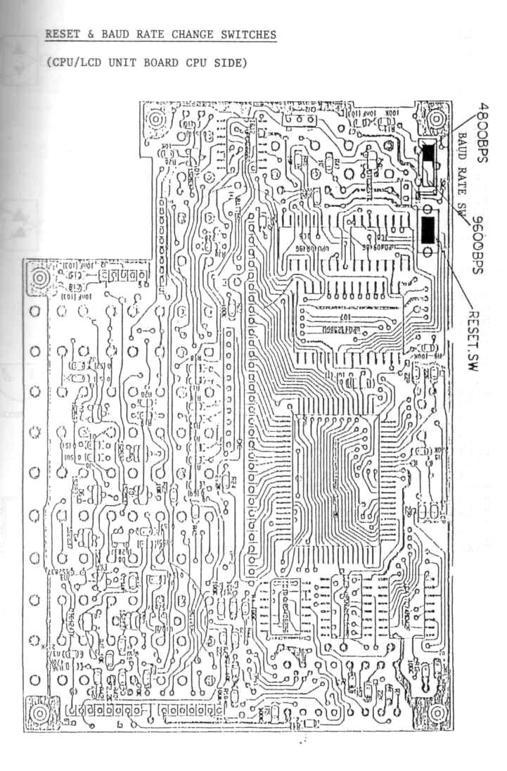
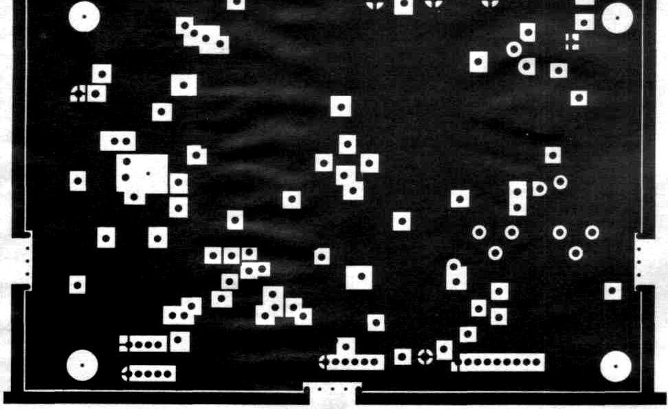
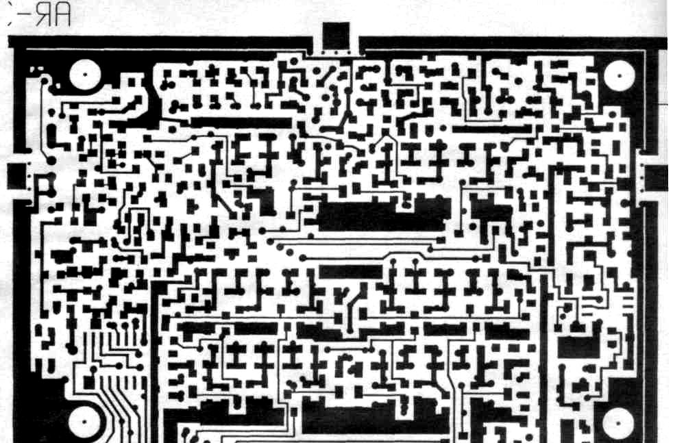
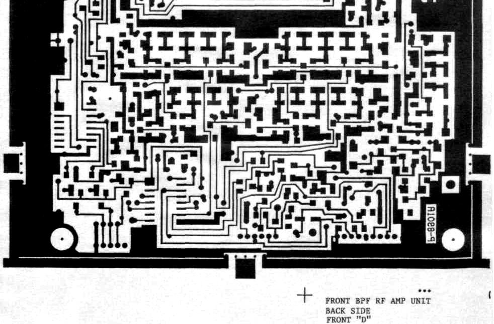
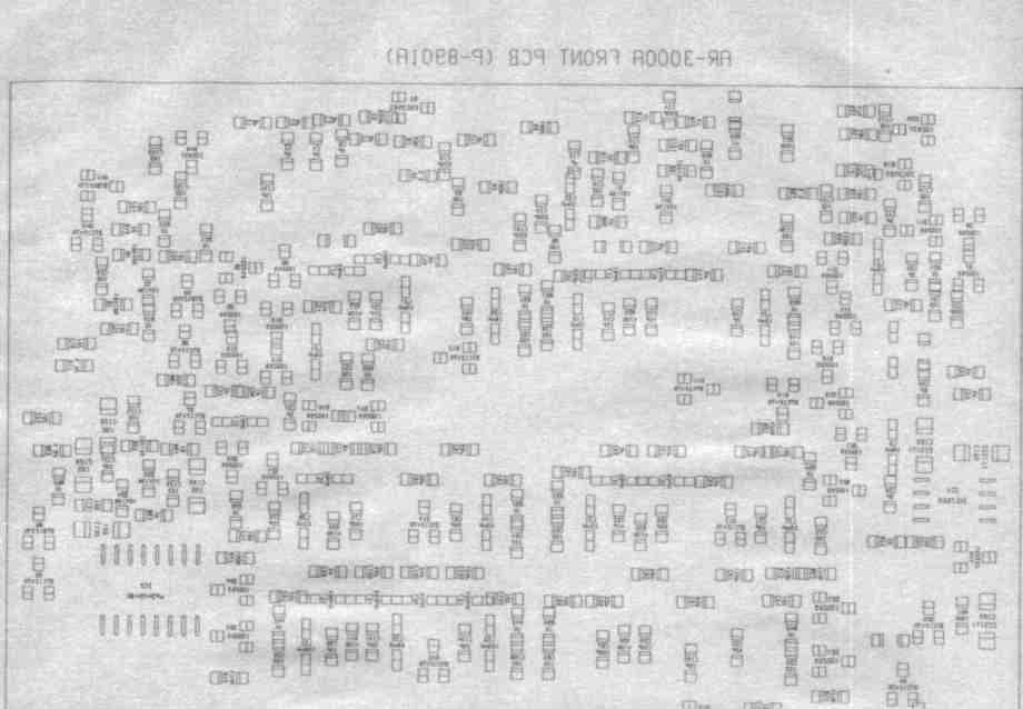
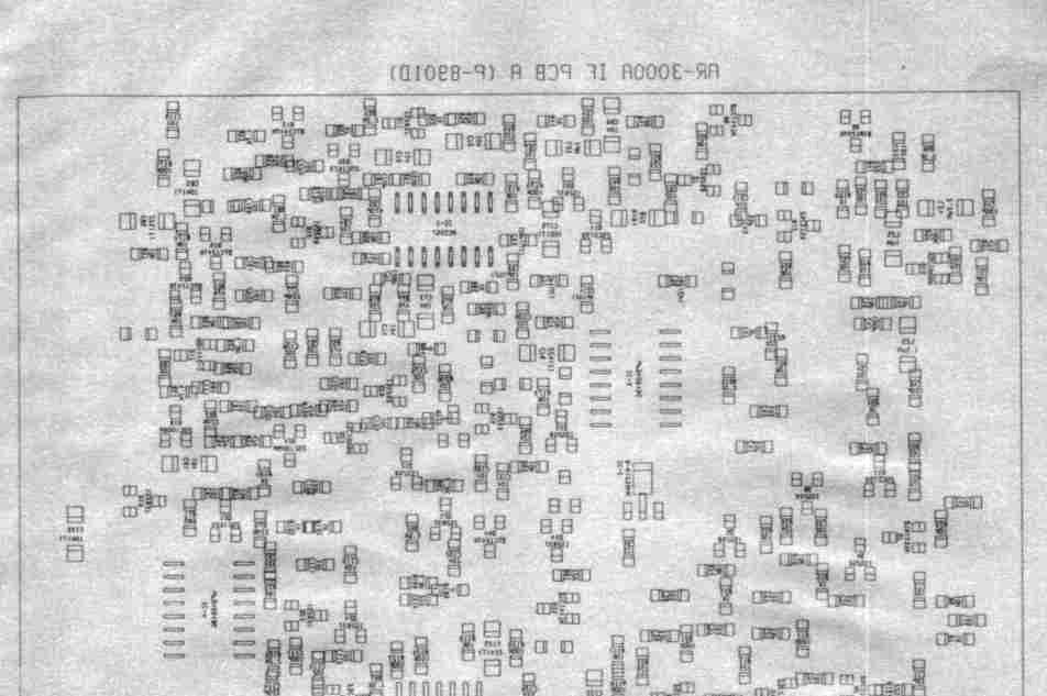
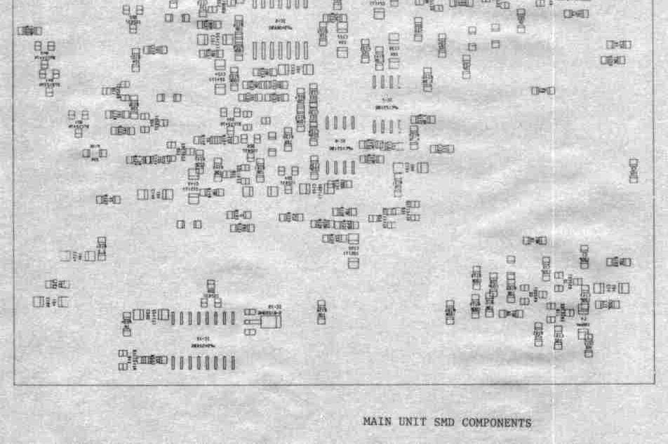
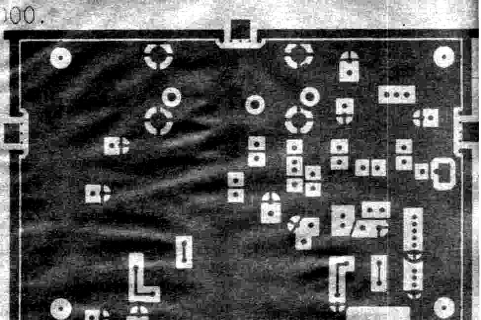
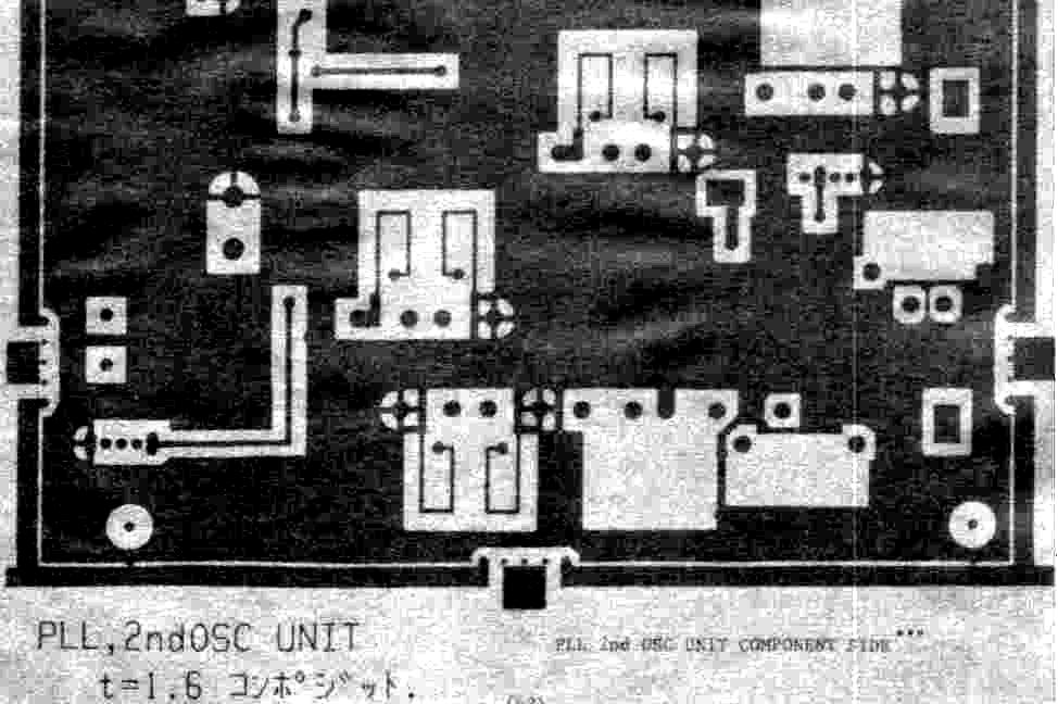
2 AR3000A SERVICE MANUAL TABLE OF CONTENTS PAGE SPECIFICATIONS (1) BLOCK DIAGRAM (2) THEORY OF OPERATION: MAINTENANCE: LIST OF DATA: ILLUSTRATIONS: SIGNAL PATH CIRCUITS (3) FRONT BPF RF AMP UNIT (4) MAIN UNIT (4) PLL 2nd OSC UNIT (5) CPU-LCD UNIT (5) TEST EQUIPMENT REQUIRED (6) ALIGNMENT AND CALIBRATION (6) FRONT BPF RF AMP UNIT (6) - (13) PLL 2nd OSC UNIT (13) MAIN UNIT (14) - (17) CHECK (18) DC VOLTAGE (19) - (20) BIRDIE LIST (21) RESET & BAUD RATE CHANGE SWITCH (22) SEMI-CONDUCTORS (23) - (27) RF COILS (28) FRONT PANEL ASSEMBLY (28) PARTS LIST (MISCELLANEOUS) (29) EXPLODED VIEW (30) PRINTED CIRCUIT BOARDS SEE THROUGH FRONT BPF RF AMP UNIT (31) - (36) MAIN UNIT (37) - (40) PLL 2nd OSC UNIT (41) - (44) CPU-LCD UNIT (45) - (48) REMOTE/EXT. SP/HEAD PHONE UNIT (49) - (52) SCHEMATIC DIAGRAMS: FRONT BPF RF AMP UNIT (53) MAIN UNIT (54) PLL 2nd OSC UNIT (55) CPU-LCD UNIT (56)
3
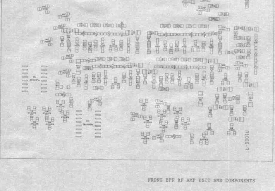
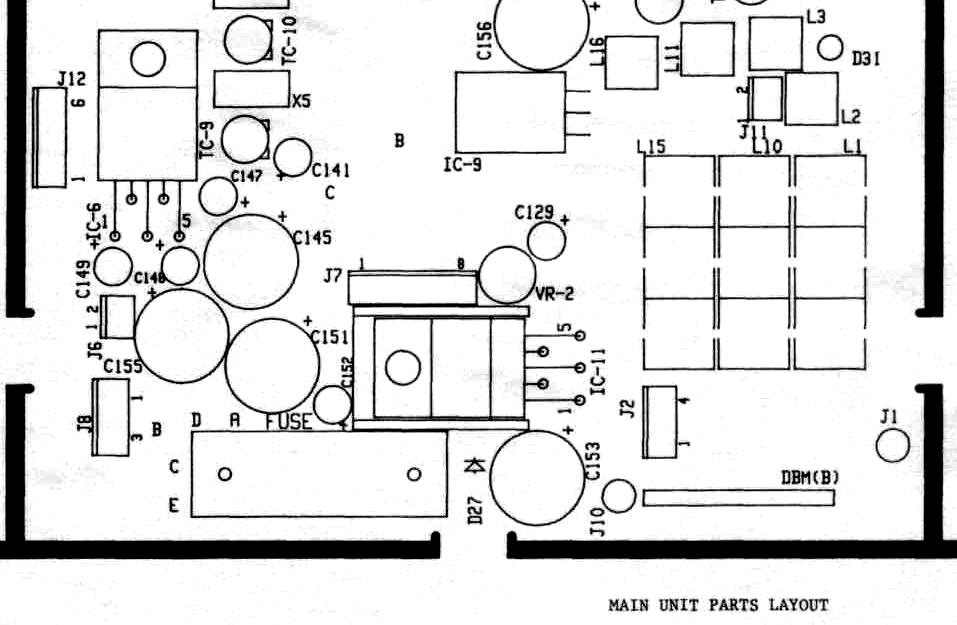
4 SIGNAL PATH CIRCUITS: Refer to the block diagram of the AR 3000A. All signals from antenna connector are switched into two attenuators for below 30MHz or above 30MHz. Succeeding 11 BPF(band pass filters) and one each LPF(low pass filter) and HPF(high pass filter) are prepared for 13 frequency ranges for pre-selection before RF amplifiers. Three RF amplifiers are provided for frequency ranges for below 30MHz, MHz & MHz. In the MAIN UNIT, signal from RF amplifier enters into DBM (double balanced mixer), then mixed with local carrier frequency of MHz to produce three kind IF frequencies as follow: MHz for 100KHz - 500MHz & 1650MHz MHz MHz for 500MHz - 940MHz 1300MHz MHz MHZ for 940MHz MHz Three BPF for each IF frequencies according to receiving frequency range are followed. Post MHz BPF, signal is mixed with 2nd local carrier of fixed MHz to produce 45.03MHz 2nd IF frequency, then amplified to compensate the loss in the 2nd DBM mixer. Signals pass through two BPFs, MHz & MHz, are mixed with different fixed 2nd local carrier of 307.2MHz & 153.6MHz to produce same 45.03MHz 2nd IF frequency accordingly. All mode except for WFM(wide) signal passes through crystal filter MHz. In case of WFM(wide), signal is mixed with crystal oscillator 34.33MHz to get 10.7MHz IF for suitable selectivity for WFM, then amplified and mixed again to recover 45.03MHz. Amplified45.03MHzsignalentersintocombination1 С,for3rdmixer,VCXO,FMIFamplifier, FM detector, squelch noise amplifier and squelch control. VCXO(voltage controlled crystal oscillator) oscillates MHz, varying 10KHz controlled by D-A (digital to analog) converter in wanted frequency steps by CPU. Subtracted 455KHz signal passes through three kind of filters selected by its mode, then buffered and re-enters into combination 1С for FM detection and squelch function. For AM/SSB/CW signals, separate AM IF amplifier is provided to follow AGC/AM detector and product detector for SSB/CW signals. Crystal controlled BFO(beat frequency oscillator) injects stable carrier 453.5KHz or 456.5KHz according to its side band (LSB or USB). Mode switch selects detector outputs for wanted mode, then audio signal passes through audio bandpass filter 300Hz Hz for NFM/AM/SSB or low pass filter 20KHz for WFM. Next audio signal is gated for squelch mute and followed into audio power amplifier to drive internal speaker. FRONT BPF RF AMP UNIT Mechanical relay selects two attenuators for below 30MHz/20dB or beyond 30MHz/10dB frequency ranges. For below 30MHz, three BPFs, one LPF and one RF amplifier are prepared by bipolar transistor 2SC3356. For beyond 30MHz { seven BPFs, one HPF and two RF amplifiers are prepared by combination of transistor 2SC3585/FET 2SK571. All necessary switchings are automatically controlled by CPU in CPU-LCD UNIT. MAIN UNIT DiodepackageHP alongwithtwotransformersworksasDBM(doublebalancedmixer) and the first mixer of the AR3000A. The first IF amplifier AGC controlled by transistor 2SC3585 is provided for all signals, and then three BPFs for different IF frequencies follow. BPF for MHz is for the lowend and the highend receiving bands, and followed by similardbmsecondmixerandthesecondifamplifierwhichisagccontrolledbytransistor 2SC2759. BPF for MHz is for MHZ and MHZ receiving bands and followed by transistor second mixer by 2SC2759. BPF for MHz is for MHz receivingband and followed by transistor second mixer by 2SC2759, as well. All injection carriers of four kinds are supplied by PLL 2nd OSC UNIT. All signals are now converted to same MHz, and it passes through crystal filter for all modes except WFM mode. In WFM mode, MHz signal is mixed with 34.33MHz crystal oscillator to make 10.7MHz IF frequency for the ceramic filter SFT10.7-MS2-A with proper bandwidth for WFM mode. 10.7MHz signal is mixed again with same 34.33MHz crystal osci-lator to recover MHz. For two mixers, diode package of MD487C1-3R along with RF transformers are used. Two stage of IF amplifiers, one for 10.7MHz and one for MHz, are provided to compensate losses through filter and two passive
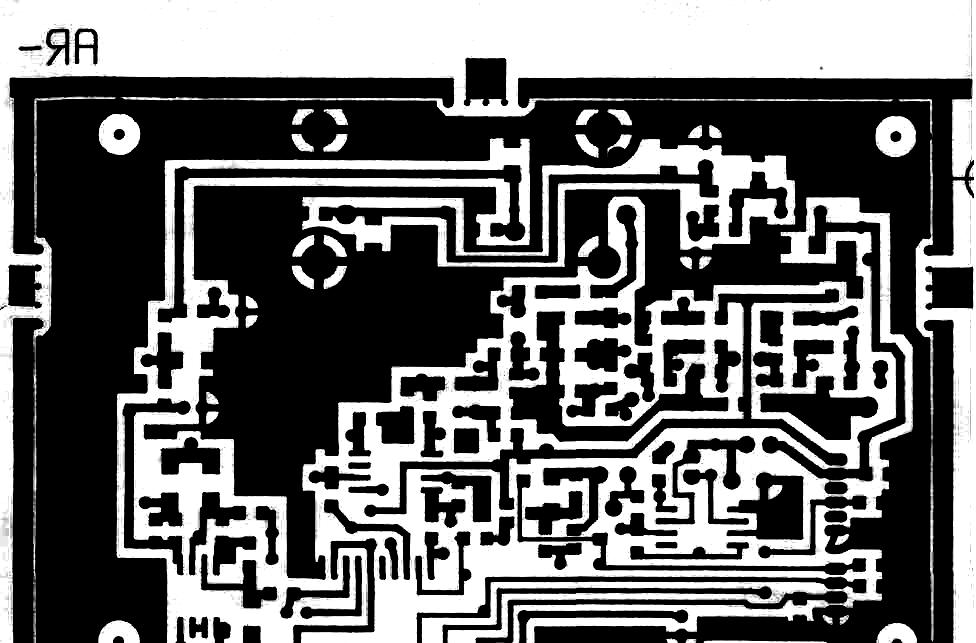
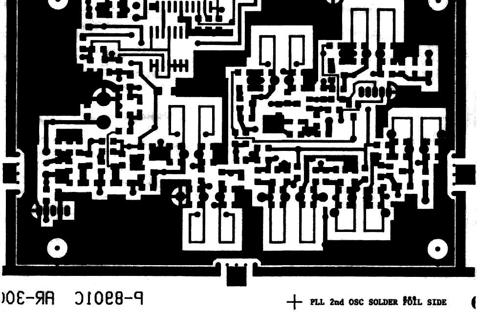
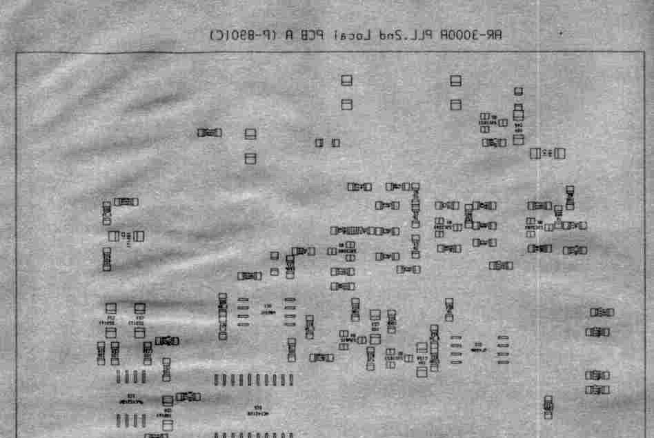
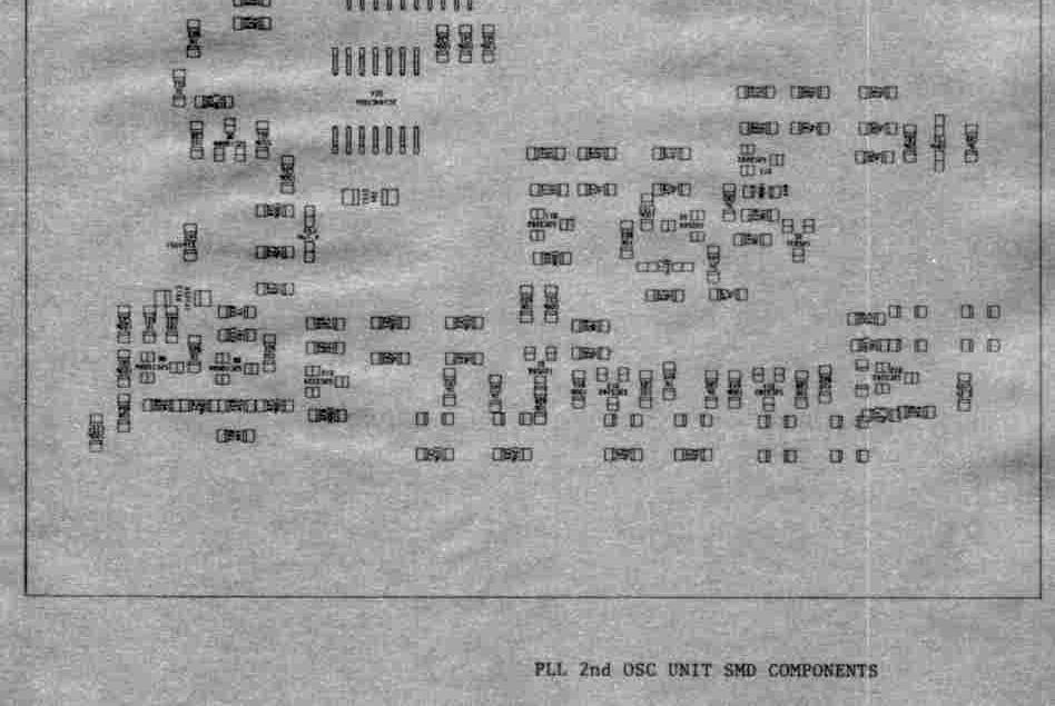
5 mixers. Filtered MHz signal is amplified again in Q MHz amplifier by transistor 2SC2759, and then enters into IC-1 MC3357 combination chip for the third mixer, VCXO(voltage controlledcrystaloscillator), FM IFamplifier, FM detector,squelchnoise amplifier and squelch control. VCXO oscillates MHz, varying 10KHz in required frequency steps(the finest 50Hz for SSB tuning) which is controlled by D-A converter under control of CPU. Converted 455KHz signal passes through three kind IF filters selected by its mode, then buffered and re-enters into MC3357 1Сfor FM detection and squelch control. Ceramic filter CFJ455K for SSB/CW 2.4KHz ( CFZM455F for NFM/AM and RF tuned coil for WFM 70KHz are provided. For AM/SSB/CW, separate IF amplifier is provided to follow AGC/AM detector and product detector for SSB/CW. Stable crystal beat oscillator for 453.5/456.5KHz injects appropriate carrier according to required side band receiving. Mode switch selects detector output for required mode, then it's detected audio signal passes through AF BPF of responsed HZ for NFM/AM/SSB or AF LPF of 20KHz cutoff for WFM. Finally audio signal is buffer-amplified and gated for squelch mute and followed to power amplifier to get enough audio power level to drive internal speaker. PLL 2nd OSC UNIT All injection carriers, the first local of MHz and the second locals of fixed 153.6MHz/307.2MHz/691.2MHz are generated and amplified to the suitable levels in this unit. The first local of MHz is generated by VCO NIS-130 special hybrid chip in PLL circuitry. Reference frequency of MHz is obtained by prescaled 12.8MHz main reference crystal oscillator which is the original reference for all injection carriers, and its stability should be very stable in temperature and other environmental changes. Control data signal is supplied by CPU-LCD UNIT for required frequency. The main reference 12.8MHz crystal oscillator is followed by buffer amplifier to feed LPF and multiplier to get 76.8MHz. 76.8MHz carrier is multiplied and amplified to get 153.6MHz MHz carrier is multiplied and amplified again to get 307.2MHz. For 691.2MHz, 76.8MHz carrier is multiplied by two stage of tripplers, then amplified to suitable level MHz(12.8 x 12) 307.2MHz(12.8 x 24) Stability: 5 PPM -10 centigrade to +50 centigrade 691.2MHZ(12.8 X 54) DC-DC converter raises 9 V DC up to 30 V DC by 1С TL499A. CPU-LCD UNIT This unit consists of CPU, LCD display, keyboard and RS232C interface. UPD75316G is CMOS 4 bit single chip microprocessor in 80 pin flat package featured with high speed function and included programmable LCD display controller/driver. Two quartz crystals MHz & KHz are used for system and timer clock accordingly. All necessary control signals are generated here and fed to three units(front BPF RF AMP, MAIN AND PLL 2nd OSC UNITS). LCD panel displays all important parameters of frequency, mode, signal strength, memory channel number, time, keylock etc. RS232C remote unit board is connected to CPU-LCD unit for remote control by an external computer. Lithium battery(3 V) backs up memory storage for approx. two years.
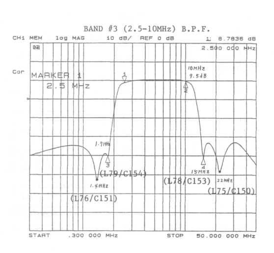
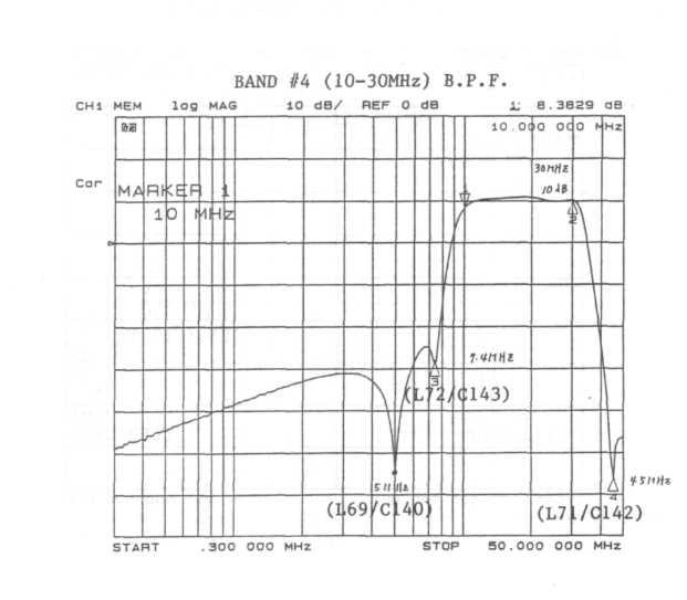
6 MAINTENANCE COVER REMOVAL Remove the two screws near the rubber feet on the bottom of the AR3000A. Remove four screws of the back side of the case. Remove the lower case by pulling down and then lift upward the back wall of the upper case and pull backward to remove the upper case. TEST EQUIPMENT REQUIRED Following is a list of test equipments recommended for maintenance of this receiver. 1. DC power supply well regulated 12V lampere capacity. 2. DC volt meter 3. AC volt meter 4. SINAD meter 5. Oscilloscope with 10MHz response 6. Frequency counter with 1300MHz response and -20dBm sensitivity 7. Signal Generator with range of 455kHz to 2300MHz preferable. S.G. with 1000MHz range can be used for extra range as one half frequency generator calibrated with a spectrum analyzer. 8. Spectrum analyzer with 2300MHz response 9. Tracking generator with 2300MHz response 10. Distortion meter ALIGNMENT AND CALIBRATION It is not necessary to align a new receiver. Each receiver is carefully aligned and checked by our expert technicians before it is forwarded from the factory. If it comes necessary to align any of the units in the AR3000A receiver, proceed as follows: FRONT END BPF RF AMP ALIGNMENT No alignment required for up to BNAD #6(50-108MHz) as fixed value inductors & capacitors are included. For more than BAND #7( MHz), critical alignment can be made when specified equipments mentioned above are available. Never try to align or adjust inductors/capacitors without above mentioned equipments. 1. Bias adjustment required prior to BPF alignment. Three potentiometers VR1,2 & 3 are on the front end board. Adjust these potentiometers as follow: VR1: Set receiving frequency of the receiver at any point in MHz range(band #5-12). Connect DC voltmeter at drain of Q19 2SK571 and adjust VR1 to get 3.6V DC. VR2: Set receiving frequency of the receiver at any point in MHz range(band #13). Connect DC voltmeter at drain of Q2 2SK571 and adjust VR2 to get 3.1V DC. VR3: Set receiving frequency of the receiver at any point in MHz range(band #13). Connect DC voltmeter at drain of Q3 2SK571 and adjust VR3 to get 3.1V DC. For above adjustment, step frequency & mode of the receiver are not important. 2. For BAND #1 through BAND #6, no adjustment parts existed but if it is necessary to confirm passband characteristics, check it by spectrum analyzer and tracking generator as follow: Connect output of tracking generator to antenna input of the AR3000A and input of spectrumanalyzertoj-4(outputterminal)offrontbpfrfampboard.characteristics of each band should be similar as follows:
7
8
9
10
11
12
13 Adjust three coils LI, 2 & 3 for 740, 880 & 820MHz respectively. Then adjust L4 It for the most flta response. PLL 2ND OSC UNIT ALIGNMENT 1. MASTER OSCILLATOR ADJUSTMENT (12.8MHz CRYSTAL OSCILLATOR) Set the AR3000A as follow and connect the frequency counter at J10 of the MAIN UNIT. STEP: 50Hz, MODE: AM/NFM/WFM, FREQUENCY: MHz Adjust TC-1 trimmer capacitor carefully to get precise frequency of MHz on the counter Remove the frequency counter and check the RF level of +3dBm to +8dBm at J10 connector by the spectrum analyzer MHz INJECTION Set the AR3000A as follow and connect the frequency counter and the spectrum analyzer at J4 of MAIN UNIT. STEP: 50Hz, MODE: AM/NFM/WFM, FREQUENCY: MHz Then adjust trimmer capacitors TC2,3,4,5,6 & 7 to get MHz and RF level of -3dBm to 0 dbm MHz INJECTION Set the AR3000A as follow and connect the frequency counter and the spectrum analyzer at J5 of MAIN UNIT. STEP: 50Hz, MODE: AM/NFM/WFM, FREQUENCY: MHz Then adjust trimmer capacitors TC8 & 9 to get MHz and RF level of -3dBm to 0 dbm MHz INJECTION Set the AR3000A as follow and connect the frequency counter and the spectrum analyzer at Jll of MAIN UNIT. STEP: 50Hz, MODE: AM/NFM/WFM, FREQUENCY: MHz Then adjust trimmer capacitors TC10,ll,12,13,14 & 15 to get mhz and RF level of -3dBm to OdBm.
14 MAIN UNIT ALIGNMENT 1. VCXO ADJUSTMENT (44.575MHz) *Special made pick-up coil(airwound 7 turn 10mm diameter by 1.2mm0 enamel coated copper wire soldered directly to BNC socket) and *Tuned amplifier (44.570MHz tuned three stage amplifier, gain 50dB) are required for this adjustment. Set the pick-up coil near to L30 coil on the AR3000A board shown as above illustration. Loose coupling to avoid frequency change is required. Connect coaxial cable with BNC plugs to the pick-up coil and other end of the cable to input of tuned amplifier. Connect frequency counter to output of 50dB gain tuned amplifier. Set thear3000aat mhz,stepadj 6kHz, AM or NFMorWFM,adjust L30 slug core for MHz +200Hz -OHz on the counter. Change the frequency to MHz, adjust VR1 potentiometer near L30 for MHZ +200Hz -OHz. Above two processes interact each other and repeat several times until no more improvement is obtained. 2. SSB CRYSTAL ADJUSTMENT (453.50/456.50kHz) Special pick-up coil and tuned 50dB gain amplifier are required for this adjustment. Pick-up coil as same as above except cold end is open not soldered to groundside of BNC connector. Tunedtwo stageamplifier of total gain of approx. 50dB. Set the pick-up coil with coaxial cable near to X6 crystal unit shown as above illustration.(same position for two trimmer caps.) Set the AR3000A at any of MHz, STEP 50Hz, MODE LSB, adjust TC9 trimmer capacitor to get kHz+200Hz-0Hz. MODE USB, adjust TC10 " " kHz+200Hz-0Hz.
15 3. MCF (MONOLITHIC CRYSTAL FILTER) ADJUSTMENT set the receiver STEP for 50Hz, MODE for AM or NFM, FREQUENCY MHz. Connectoutputofthetrackinggeneratorthrough1000PF capacitor to base of Q2 2SC2759 and the spectrum analyzer at pin //16 of IC1 MC3357 through 1000PF capacitor. Adjust ferrite cores of transformersl7,19 &20togetflatandhighestresponseasshownbelow. Output level of the tracking generator: -50dBm Change receiving frequency to MHz and output of the tracking generator to emitter of Q4 2SC2759 through 1000PF capacitor. Adjust ferrite core of transformer L14 to get flat and highest response as shown below. Output level of the tracking generator: -30dBm
16 Change receiving frequency to MHz and output of the tracking generator to emitter of Q6 2SC2759 through 1000PF capacitor. Adjsut ferrite core of transformer L18 to get flat and highest response as shown below. Output level of the tracking generator: -30dBm 4. HELICAL RESONATORS & INJECTION LEVEL ALIGNMENT Set the receiver, STEP: 50Hz, MODE: AM, FREQUENCY: MHz and connect the signal generator output to antenna jack of the receiver. Connect 8 ohm 2 watts non-inductive resistor as an external load to external speaker jack and paralleled with oscilloscope, AC voltmeter & SINAD meter. Also connect DC voltmeter at pin #10 of J9 connector of the main unit board for AGC voltage. Set the VR5 potentiometer at fully clockwise position in this stage. Set SG frequency MHz and modulation AM 60% and output level to indicate 3.0 V DC at pin #10 of J9 (AGC) on the DC voltmeter. Set SG output off then adjust VR3 potentiometer to get 4.8 V on the DC voltmeter. Then set SG output on and adjust helical resonator L_l (three metal screws), RF transformers L29 & 31 for minimum indication on DC voltmeter. Check lodb signal to noise ratio is obtainable at less than +6dBu EMF input for the receiver. In same setting as above except frequency change of receiver/sg to MHz, adjust helical resonator L10 (three metal screws) and trimmer capacitor TC7 for minimum indication on DC voltmeter. Check lodb signal to noise ratio is obtainable at less than +6dBu EMF input for the receiver.
17 Remain same setting as above adjustment except frequency change to MHz, then adjust the helical resonator L15 (three metal screws) and trimmer capacitor TC8 for minimum indication on DC voltmeter. Check if lodb signal to noise ratio is obtainable at less than +6dBu EMF input for the receiver. Change frequency of the receiver/sg to MHz and set SG output level for dBu EMF. Adjust trimmer capacitor TC6 for minimum deflection of the SINAD meter. Check if lodb signal to noise ratio is obtainable at less than +12dBu EMF input for the receiver KHz ADJUSTMENT Remain same setting as above 4. alignment, change MODE to WFM and frequency to MHz, SG modulation FM 50KHz deviation and output level for 50dBu EMF. Adjust transformer L28 to get synmetric and largest wave form on the oscilloscope screen. Check if 12dB SINAD is obtainable at less than +6dBu EMF input for the receiver. Change MODE to NFM and frequency to MHz, SG modulation FM with 3.5KHz deviation and output level for -3dBu EMF. Adust transformer L29 for minimum deflection on SINAD meter. Check if 12dB SINAD is obtainable at less than -3dBu EMF input for the receiver. 6. S METER ADJUSTMENT Set the receiver at MHz, AM mode, 50Hz step and connect SG output to antenna jack of the receiver same frequency, OdBu EMF, no modulation. Adjust potentiometer VR5 (fully clockwise positioned in early stage of adjustment) for two dots indication on the LCD display. Change frequency to MHz and check if two dots S indication occurs with -3 to +6dBu EMF input for the receiver. Change frequency to MHz and check if two dots S indication occurs with -3 to +6dBu EMF input for ther receiver. Set the receiver at MHz, WFM mode, 50Hz step and connect SG output to antenna jack of the receiver same frequency, +3dBu EMF level, no modulation. Adjust potentiometer VR4 for two dots indication on the LCD "S" display.
18 CHECK 1. SENSITIVITY Set the receiver MHz, NFM mode, 50Hz step and connect SG setting with same frequency, -3dBu EMF output, FM modulation 3.5KHz deviation to antenna jack. Connect SINAD meter to the external speaker jack of the receiver paralleled with 8 ohm non-inductive resistor as a dummy load. Check if more than 12dB SINAD is obtained. Change frequency of the receiver and SG to MHz, SG output level to +6dBu EMF. Check if more than 12dB SINAD is obtained. 2. DISTORTION ON SSB/CW Set the receiver MHz, LSB mode, 50Hz step and connect SG setting MHz, no modulation, 50dBu EMF output level to antenna jack. Connect distortion meter to the external speaker jack of the receiver paralleled with 8 ohm non-inductive resistor and the frequency counter for audio range. Check if audio output tone of the receiver is within Hz and in less than 30% distortion. Change receiving mode to USB and SG frequency to MHz. Check if the output beat tone of the receiver within Hz and in less than 30% distortion. ChangereceivingmodetoCWandSGfrequencyto MHz.Check if the output beat tone is within Hz and in less than 30% distortion.
19 AR3000A FRONT UNIT DC VOLTAGE PART NO. BASE COLLECTOR EMITTER REMARKS Q40 DTC124TK 4.4(V) 0.0(V) GND 100KHZ-30MHZ Q40 DTC124TK GND 940MHz-2036MHz Q40 DTC124TK GND 30MHZ-940MHZ Q41 DTB123YK KHZ-30MHZ 940MHZ-2036MHZ Q41 DTB123YK MHZ-940MHZ Q5 DTC124TK GND ATT ON Q5 DTC124TK GND ATT OFF Q6 DTC124TK GND ATT ON Q6 DTC124TK GND ATT OFF Q7 DTC124TK GND ATT ON Q7 DTC124TK GND ATT OFF Q8 DTC124TK GND ATT ON Q8 DTC124TK GND ATT OFF Q9 DTB123YK ATT ON Q9 DTB123YK ATT OFF Q24 DTC124TK GND KHZ ON Q24 DTC124TK GND KHZ OFF Q23 DTC124TK GND 500KHZ-2.5MHz ON Q23 DTC124TK GND 500KHZ-2.5MHz OFF Q22 DTC124TK GND 2.5-lOMHz ON Q22 DTC124TK GND 2.5-lOMHz OFF Q21 DTC124TK GND 10-30MHz ON Q21 DTC124TK GND 10-30MHz OFF Q17 DTC124TK GND 30-50MHZ ON Q17 DTC124TK GND 30-50MHZ OFF Q16 DTC124TK GND MHZ ON Q16 DTC124TK GND MHZ OFF Q15 DTC124TK GND MHZ ON Q15 DTC124TK GND MHZ OFF Q14 DTC124TK GND MHZ ON Q14 DTC124TK GND MHZ OFF Q13 DTC124TK GND MHZ ON Q13 DTC124TK GND MHZ OFF Q12 DTC124TK GND MHZ ON Q12 DTC124TK GND MHZ OFF Qll DTC124TK GND MHZ ON Qll DTC124TK GND MHZ OFF Q10 DTC124TK GND MHZ ON Q10 DTC124TK GND MHZ OFF Ql 2SC GND MHZ ON Q2 2SK571 -(G) 3.1(D) GND(S) MHZ ON Q3 2SK571 -(G) 3.1(D) GND(S) MHZ ON Q4 DTC124TK GND MHz ON Q4 DTC124TK GND MHZ OFF Q25 2SC GND 100KHZ-30MHZ ON Q26 DTC124TK GND 100KHz-30MHz ON Q26 DTC124TK GND 100KHZ-30MHZ ON Q18 2SC GND MHZ ON Q19 2SK571 -(G) 3.6(D) GND(S) MHZ ON Q20 DTC124TK GND MHZ ON Q20 DTC124TK GND MHZ OFF Q35 DTC124TK GND MHZ ON Q35 DTC124TK GND MHZ OFF Q36 DTC124TK GND MHZ ON
20 PART NO. BASECOLLECTOR EMITTER REMARKS Q36 DTC124TK GND MHZ OFF Q37 DTB123YK MHZ ON Q37 DTB123YK MH2 OFF Q33 DTC124TK GND MHZ ON Q33 DTC124TK GND MHZ OFF Q34 DTB123YK MHZ О Q34 DTB123YK MHZ OFF Q38 DTC124TK GND 100KHZ-30MHZ ON Q38 DTC124TK GND 100KHZ-30MHZ OFF Q39 DTB123YK KHZ-30MHZ ON Q39 DTB123YK KHZ-30MHZ OFF Q31 DTC124TK GND 100KHZ-500MHZ ON Q31 DTC124TK GND 100KHz-500MHz OFF Q32 DTB123YK KHZ-500MHZ ON Q32 DTB123YK KHZ-500MHZ OFF Q29 DTC124TK GND MHZ ON Q29 DTC124TK GND MHZ OFF Q30 DTB123YK MHZ ON Q30 DTB123YK MHZ OFF 027 DTC124TK GND MHZ ON Q27 DTC124TK GND MHZ OFF Q28 DTB123YK MHZ ON Q28 DTB123YK MHZ OFF
21 AR3000A FRONT UNIT DC VOLTAGE PART NO. ANODE CATHODE REMARKS D37 1SS (V) 4.1(V) K-C KHZ D37 1SS K-C lOMHz D39 1SS K-C KH2 D39 1SS K-C KHZ-2.5MHz D38 1SS KHZ-2.5MHz D35 1SS MHZ D36 1SS K-C lOMHz D36 1SS K-C MHZ D34 1SV ATT OFF 100KHz-30MHz MHZ D32 1SV ATT ON 100KHZ-30MHZ MHZ D33 1SV ATT ON 100KHz-30MHz MHZ D45 1S A-Q KHZ D45 1S A-Q MHZ D46 1S A-Q23 500KHZ-2.5MHz D46 1S A-Q lOMHz D28 1SS MHZ D29 1SS MHZ D26 1SS MHZ D27 1SS MHZ D22 1SS K-C MHZ D22 1SS K-C MHZ D25 1SS K-C MHZ D25 1SS K-C MHZ D24 1SS MHZ D23 1SS MHZ D16 1SS MHZ D17 1SS MHZ D19 1SS MHZ D18 1SS MHZ D12 1SS MHZ D13 1SS MHZ D15 1SS MHZ D14 1SS MHZ D5 1SS MHZ D6 1SS MHZ D8 1SS MHZ D7 1SS MHZ D4 1SV ATT OFF MHZ D2 1SV ATT ON MHZ D3 1SV ATT ON MHZ D9 1SS MHZ D9 1SS MHZ D9 1SS KHZ-30MHZ M] D10 1SS MHZ D10 1SS MHZ D10 1SS KHZ-30MHZ M D20 1SS MHZ D20 1SS MHZ D20 1SS KHZ-30MHZ M Dll 1SS MHZ Dll 1SS MHZ Dll 1SS KHZ-30MHZ M D21 1SS MHZ D21 1SS MHZ D21 1SS KHz-30MHz M D41 1SV (8.4) 100KHZ-30MHZ (OFF)
22 PART NO. ANODE CATHODE REMARKS D31 1SV (8.5) MHZ (OFF) Dl 1SV (8.5) MHZ (OFF) D47 1S A-Q38 100KHZ-30MHZ D47 1S A-Q MHZ D50 1S MHZ D49 1S MHZ D51 1S A-Q MHZ D51 1S A-Q39 100KHZ-30MHZ D44 1S A-D MHZ D44 1S A-D MHZ
23 AR3000A PLL UNIT DC VOLTAGE PART NO. BASE COLLECTOR EMITTER REMARKS Q8 2SC1009A 2.34(V) 4.96(V) 1.88(V) Q9 2SC1009A GND Q10 2SC GND Qll 2SC GND Q12 2SC GND Q13 2SC GND Q14 2SC GND Q15 2SC GND Ql 2SC GND Q2 2SC GND 3 2SC GND 4 2SA WHEN PLL LOCKED 4 2SA WHEN PLL UNLOCKED 5 2SC GND WHEN PLL LOCKED Q5 2SC GND WHEN PLL UNLOCKED Q6 2SC1009A GND Q7 2SC
24
25 AR3000A MAIN UNIT DC VOLTAGE PART NO. ANODE CATHODE REMARKS D4 1SS (V) 2.13(V) lookhz mhz 1650MHZ-2036MHZ D5 1SS MHZ MHz ANODE L MHZ MHz D5 1SS MHZ MHz ANODE L18 D6 1SS OTHER THAN WFM ANODE R27 D6 1SS WFM ANODE R29 D7 1SS OTHER THAN WFM ANODE L20 D7 1SS WFM ANODE R30 D15 1SS NFM AM ANODE R89 D15 1SS LSB ANODE R91 D15 1SS USB CW ANODE R91 D17 1SS NFM AM ANODE R90 D17 1SS LSB ANODE R92 D17 1SS USB CW ANODE R92 D28 1SS WFM CATHODE R2O6 D28 1SS WFM CATHODE R173 D16 1SS WFM CATHODE R173 D16 1SS WFM CATHODE R93 D21 1SS GND LSB 100KHz MHz ANODE R106 D21 1SS GND USB CW 940MHZ-2036MHZ ANODE R106 D21 1SS GND USB CW 100KHz MHZ ANODE R107 D21 1SS GND LSB 940MHZ-2036MHZ ANODE R107 D20 1S LSB D20 1S USB CW ANODE D22 D22 1S USB D22 1S CW D19 1S NFM D19 1S AM D10 1SS NFM AM ANODE R81 D10 1SS WFM ANODE R80 D10 1SS LSB ANODE R81 D10 1SS USB CW ANODE R81 D29 1S NFM AM ANODE D19 D29 1S LSB ANODE D20 D29 1S USB CW ANODE D20 D14 1S WFM D14 1S LSB ANODE D20 D14 1S USB CW ANODE D20 D12 ND CATHODE C88 ANODE R65 D12 ND CATHODE R68 Dll 1S NFM AM SQ-VR MIN Dll 1S NFM AM SQ-VR THRESHOLD Dll 1S NFM AM SQ-VR MAX Dll 1S WFM SQ-VR MIN Dll 1S WFM SQ-VR THRESHOLD Dll 1S WFM SQ-VR MAX Dll 1S SSB SQ-VR MIN Dll 1S SSB SQ-VR THRESHOLD Dll 1S SSB SQ-VR MAX D23 1S USB D23 1S CW D24 1S LSB D26 1S WHEN PLL LOCK ANODE R184
26 PART NO. ANODE CATHODE REMARKS D2 6 1S WHEN PLL UNLOCK ANODE R184 D26 1S WHEN SQ-OFF ANODE R202 D26 1S WHEN SQ-ON ANODE R S WHEN SQ-OFF ANODE MC D36 1S WHEN SQ-ON ANODE MC PIN-NO VOLTAGE REMARKS IC-1 MC SQ-VR FULL CLOCKWISE POSITION 13 OPEN (SQ-OFF) 0.00(SQ-ON) 15 GND
27 BIRDIE LIST Every complex receiver has frequencies that are difficult or impossibletoreceivebecauseofinternallygeneratedsignals.these frequencies are called "BIRDIES". The following is a partial list of such frequencies that may occur in the AR3000. (Noted at 12' oclock squelch control position) 1.59МНz MHz MHz In addition, there are other frequencies that are difficult to receive because of interference from externally generated signals, such as T.V. stations, other receivers nearby and various other sources of man-made noise. These frequencies vary from location to location and are therefore impossible to list. When this type of interference is encountered, it can sometimes be eliminated by moving the squelch control knob counterclockwise (increase squelch action).
28
29 BIRDIE LIST Every complex receiver has frequencies that are difficult or impossible to receive because of internally generated signals. These frequencies are called "BIRDIES". The following is a partial list of such frequencies that may occur in the AR3000. (Noted at 12' oclock squelch control position) 1.59MHz MHz MHz " In addition, there are other frequencies that are difficult to receive because of interference from externally generated signals, such as T.V. stations, other receivers nearby and various other sources of man-made noise. These frequencies vary from location to location and are therefore impossible to list. When this type of interference is encountered, it can sometimes be eliminated by moving the squelch control knob counterclockwise (increase squelch action).
30 SEMI CONDUCTORS * DIODES * TRANSISTORS 1S2837 SWITCHING 2SA812 1SS123 1SS268 " " 2SC1009A 2SC1623 1SS269 " 2SC2759 1SS272 1S1588 " 2SC3356 " 2SC3585 RB100A RECTIFIER 2SK571 GaAs MOS FET 1SV196 PIN DIODE 1SV163 VARI CAP. DTA123YK DTB123YK 1SV166 FC52M " " DTC124TK DTC144TK ND411G-1 PAIR DTC323TK ND487C1-3R QUAD RING * INTEGRATED CIRCUITS UA78L62 VOLTAGE REGULATOR UPC78M05H " S-8054HN VOLTAGE DETECTOR S-81250HG VOLTAGE REGULATOR L780S09 " WITH STROBE ICL7660 CMOS VOLTAGE CONVERTER TL499A SWITCHING REGULATOR UPC1251G DUAL OPERATIONAL AMPLIFIER UPD4066BG QUAD BILATERAL SWITCH UPD4094BG 8 STAGE SHIFT STORE BUS REGISTER UPD4528BG DUAL MONOSTABLE MULTIVIBRATOR UPD74HC151G 8 INPUT DATA SELECTOR/MULTIPLEXER UPD74HC42AF UPD43256AGU BCD TO DECIMAL DECODER STATIC CMOS RAM UPD75316GF 1 CHIP 4 BIT MICRO COMPUTER TC74H107AF DUAL JK FLIP FLOP WITH CLEAR MB501L 2 MODULUS HIGH SPEED PRESCALER MC3357 LOW POWER FM IF MC SERIAL INPUT PLL FREQUENCY SYNTHESIZER TC5090AP 8 BIT A/D CONVERTER UPC2002 AF POWER AMPLIFIER MAX232 RS-232 DRIVER/RECEIVER ND487C1-3R (SCHOTTKY BARRIER DIODE QUAD)
31
32
33
34
35
36
37
38
39
40
41
42
43
44
45
46
47
48
49
50
51
52
53
54
55
56
57
FT-897 Alignment. Local Oscillator Adjustment. PLL Adjustment
 FT-897 Local Oscillator Adjustment Reference Frequency Adjustment a. Connect a frequency counter to TP1032. b. Adjust the trimmer capacitor (TC5001) for 67.875000MHz ±5Hz on the frequency counter. c. Connect
MAINTENANCE MANUAL RF BOARD 19D901835G1 ( MHz) 19D901835G2 ( MHz) FOR MVS
 19D901835G2 ( MHz) FOR MVS") D MAINTENANCE MANUAL F BOAD 19D901835G1 (136-153 MHz) 19D901835G2 (150-174 MHz) FO MVS TABLE OF CONTENTS DESCIPTION............................................... Front Cover CICUIT ANALYSIS..............................................
D MAINTENANCE MANUAL F BOAD 19D901835G1 (136-153 MHz) 19D901835G2 (150-174 MHz) FO MVS TABLE OF CONTENTS DESCIPTION............................................... Front Cover CICUIT ANALYSIS..............................................
ericssonz LBI-38640E MAINTENANCE MANUAL FOR VHF TRANSMITTER SYNTHESIZER MODULE 19D902780G1 DESCRIPTION
 MAINTENANCE MANUAL FOR VHF TRANSMITTER SYNTHESIZER MODULE 19D902780G1 TABLE OF CONTENTS Page DESCRIPTION........................................... Front Cover GENERAL SPECIFICATIONS...................................
Circuit Description. Receive Signal Path. CTCSS Operation. S-Meter. RX PLL & VCO Circuit. Squelch Control. RPP Programming Software Instruction
 RPP Programming Software Instruction VXR-5000 Receive Signal Path ~com.ing RF from the RX antenna jack is dehvered to the RX Unit and passes through the bandpass filter consisting of coils L4002, L4003
THEORY OF OPERATION. TM308EUL for Cobra Nov 06,2006
 THEORY OF OPERATION TM308EUL for Cobra Nov 06,2006 This PLL controlled VHF marine mobile transceiver provides an accurate and stable multi-channel operation. The transceiver consists of 15 main sections
MAINTENANCE MANUAL TRANSMITTER/RECEIVER BOARD CMN-234A/B FOR MLSU141 & MLSU241 UHF MOBILE RADIO TABLE OF CONTENTS
 MAINTENANCE MANUAL TRANSMITTER/RECEIVER BOARD CMN-234A/B FOR MLSU141 & MLSU241 UHF MOBILE RADIO TABLE OF CONTENTS DESCRIPTION... 2 CIRCUIT ANALYSIS... 2 TRANSMITTER... 2 9-Voft Regulator... 2 Exciter...
Maintenance Manual ERICSSONZ LBI-31552E
 E Maintenance Manual TONE REMOTE CONTROL BOARD 19A704686P4 (1-Frequency Transmit Receive with Channel Guard) 19A704686P6 (4-Frequency Transmit Receive with Channel Guard) ERICSSONZ Ericsson Inc. Private
HF Receivers, Part 2
 HF Receivers, Part 2 Superhet building blocks: AM, SSB/CW, FM receivers Adam Farson VA7OJ View an excellent tutorial on receivers NSARC HF Operators HF Receivers 2 1 The RF Amplifier (Preamp)! Typical
LBI-30398N. MAINTENANCE MANUAL MHz PHASE LOCK LOOP EXCITER 19D423249G1 & G2 DESCRIPTION TABLE OF CONTENTS. Page. DESCRIPTION...
 MAINTENANCE MANUAL 138-174 MHz PHASE LOCK LOOP EXCITER 19D423249G1 & G2 LBI-30398N TABLE OF CONTENTS DESCRIPTION...Front Cover CIRCUIT ANALYSIS... 1 MODIFICATION INSTRUCTIONS... 4 PARTS LIST AND PRODUCTION
Maintenance Manual TRANSMITTER/RECEIVER BOARD CMN-233 FOR MLSH041
 Maintenance Manual TRANSMITTER/RECEIVER BOARD CMN-233 FOR MLSH041 TABLE OF CONTENTS Page DESCRIPTION... 2 CIRCUIT ANALYSIS... 2 Transmitter... 2 9-volt Regulator... 2 Exciter... 2 40-Watt PA... 2 Antenna
ERICSSONZ LBI-30398P. MAINTENANCE MANUAL MHz PHASE LOCKED LOOP EXCITER 19D423249G1 & G2 DESCRIPTION TABLE OF CONTENTS
 MAINTENANCE MANUAL 138-174 MHz PHASE LOCKED LOOP EXCITER 19D423249G1 & G2 TABLE OF CONTENTS Page DESCRIPTION... Front Cover CIRCUIT ANALYSIS...1 MODIFICATION INSTRUCTIONS...4 PARTS LIST...5 PRODUCTION
KACHINA 1 SSB TRANSCEIVER
 KACHINA 1 SSB TRANSCEIVER THEORY OF OPERATION The Kachina 1 Amateur Band Transceiver is a highly sophisticated, state of the art, piece of communication equipment, housed in the smallest of packages. Yet,
AC LAB ECE-D ecestudy.wordpress.com
 PART B EXPERIMENT NO: 1 AIM: PULSE AMPLITUDE MODULATION (PAM) & DEMODULATION DATE: To study Pulse Amplitude modulation and demodulation process with relevant waveforms. APPARATUS: 1. Pulse amplitude modulation
Maintenance Manual. MTD SERIES 900 MHz, 10-WATT, DATA ONLY MOBILE RADIO. Mobile Communications LBI TABLE OF CONTENTS
 Mobile Communications MTD SERIES 900 MHz, 10-WATT, DATA ONLY MOBILE RADIO TABLE OF CONTENTS RF BOARD............................... LBI-38545 AUDIO BOARD............................ LBI-38546 LOGIC BOARD............................
MAINTENANCE MANUAL AUDIO BOARDS 19D902188G1, G2 & G3
 B MAINTENANCE MANUAL AUDIO BOARDS 19D902188G1, G2 & G3 TABLE OF CONTENTS Page Front Cover DESCRIPTION............................................... CIRCUIT ANALYSIS............................................
MAINTENANCE MANUAL UHF REAR COVER ASSEMBLY 19C337097G4 - G7, G11, G13
 LBI-38383D SCHEMATIC DIAGRAM MAINTENANCE MANUAL UHF REAR COVER ASSEMBLY 19C337097G4 - G7, G11, G13 TABLE OF CONTENTS Page DESCRIPTION........................................... Front Cover CIRCUIT ANALYSIS........................................
MASTR II AUXILIARY RECEIVER 19D417546G7 & G8 & ANTENNA MATCHING UNITS 19C321150G1-G2. Maintenance Manual LBI-30766L. Mobile Communications
 L Mobile Communications MASTR II AUXILIARY RECEIVER 19D417546G7 & G8 & ANTENNA MATCHING UNITS 19C321150G1-G2 Printed in U.S.A Maintenance Manual TABLE OF CONTENTS Page SPECIFICATIONS.....................................................
MAINTENANCE MANUAL RF BOARD 19D902243G4 ( MHz) 19D902243G5 ( MHz) 19D902243G6 ( MHz) FOR MVS
 19D902243G5 ( MHz) 19D902243G6 ( MHz) FOR MVS") LI-38258D IC DATA MAINTENANCE MANUAL F OAD 19D902243G4 (403-440 MHz) 19D902243G5 (440-470 MHz) 19D902243G6 (470-512 MHz) FO MVS OPEATIONAL AMPLIFIE 19A701789P2 QUAD ILATEAL SWITCH (U202) 19A700029P44 TALE
LI-38258D IC DATA MAINTENANCE MANUAL F OAD 19D902243G4 (403-440 MHz) 19D902243G5 (440-470 MHz) 19D902243G6 (470-512 MHz) FO MVS OPEATIONAL AMPLIFIE 19A701789P2 QUAD ILATEAL SWITCH (U202) 19A700029P44 TALE
The Uniden Grant XL Owners Site
 The Uniden Grant XL Owners Site Modifications page for the Grant XL (For Informational purposes only) The author of this site takes NO responsibility for illegal modifications and/or use of illegally modified
HF Amateur SSB Receiver
 HF Amateur SSB Receiver PCB Set for radio club project http://rhelectronics.net PCB for DIY HF Amateur SSB Receiver 20M The receiver is a simple syperheterodyne type with quartz crystal filter. The circuit
BLOCK DIAGRAM - I J Li) N 6. w IS) AF D RIVE R R F D RIVE R R F P OWE R AMP PL L OSC UNIT. LL co X X X Lti X. C X W N O C..) 4 C.
 N 6. w IS) AF D RIVE R R F D RIVE R R F P OWE R AMP PL L OSC UNIT. LL co X X X Lti X. C X W N O C..) 4 C.") MODEL 1-632 BLOCK DIAGRAM tl LL co a. LL O ox X X X X < X C.) W N C U) LL CO aa 1.11 t O - I J Ul Li) Lti N w IS) 1 X. C X Ir t AF D RIVE R X - LL C.) CD r.--1111 MOP U) N N 6 PL L OSC UNIT R F D RIVE
MODEL 1-632 BLOCK DIAGRAM tl LL co a. LL O ox X X X X < X C.) W N C U) LL CO aa 1.11 t O - I J Ul Li) Lti N w IS) 1 X. C X Ir t AF D RIVE R X - LL C.) CD r.--1111 MOP U) N N 6 PL L OSC UNIT R F D RIVE
A NEW LIFE FOR THE FT-290R TRANSCEIVER! By F5RCT
 A NEW LIFE FOR THE FT-290R TRANSCEIVER! By F5RCT The FT290R is an old amateur radio workhorse which was a very popular transceiver during the 80 s. It is a 2metre multimode portable which can run with
FREQUENCY AGILE FM MODULATOR INSTRUCTION BOOK IB
 FMT615C FREQUENCY AGILE FM MODULATOR INSTRUCTION BOOK IB1215-02 TABLE OF CONTENTS SECTION SUBJECT 1.0 Introduction 2.0 Installation & Operating Instructions 3.0 Specification 4.0 Functional Description
KN-Q10 Assembly Manual
 KN-Q10 Assembly Manual Translated by Adam Rong, BD6CR/4 with permission from Ke Shi, BA6BF Edited by Stephen, VK2RH Revision B, Oct 14, 2010 Thank you for purchasing the KN-Q10 4 Band SSB/CW Dual Mode
MASTR II BASE STATION MHz RECEIVER IF/AUDIO/SQUELCH & RF ASSEMBLY (25 khz/12.5 khz CHANNEL SPACING) Maintenance Manual LBI-38506A
 Maintenance Manual LBI-38506A") A Mobile Communications MASTR II BASE STATION 806-824 MHz RECEIVER IF/AUDIO/SQUELCH & RF ASSEMBLY (25 khz/12.5 khz CHANNEL SPACING) TABLE OF CONTENTS RF ASSEMBLY, MIXER AND IF FILTER BOARD...... LBI-30482
A Mobile Communications MASTR II BASE STATION 806-824 MHz RECEIVER IF/AUDIO/SQUELCH & RF ASSEMBLY (25 khz/12.5 khz CHANNEL SPACING) TABLE OF CONTENTS RF ASSEMBLY, MIXER AND IF FILTER BOARD...... LBI-30482
SRF-M75PM SERVICE MANUAL FM STEREO/AM PLL SYNTHESIZED RADIO. US Model Canadian Model AEP Model E Model Australian Model. Ver
 SRF-M75PM SERVICE MANUAL Ver 1.0 1999. 04 US Model Canadian Model AEP Model E Model Australian Model SPECIFICATIONS US, Canadian, and E models AEP, Australian models FM STEREO/AM PLL SYNTHESIZED RADIO
Preliminary Information (There will be updates)
") This Manual is provided by CBTricks.com Someone who wanted to help you repair your equipment put together this information. Cobra150GTL DX If you would like to help us put more manuals online support us.
This Manual is provided by CBTricks.com Someone who wanted to help you repair your equipment put together this information. Cobra150GTL DX If you would like to help us put more manuals online support us.
HT-1A Dual Band CW QRP Transceiver. Kit Building Instructions
 HT-A Dual Band CW QRP Transceiver Kit Building Instructions Rev B, July 8, 08 Designed by BD4RG Exclusively distributed by CRKITS.COM and its worldwide distributors Join the group http://groups.io/g/crkits
JUMA-TRX2 DDS / Control Board description OH2NLT
 JUMA-TRX2 DDS / Control Board description OH2NLT 22.08.2007 General Key functions of the JUMA-TRX2 DDS / Control board are: - provide user interface functions with LCD display, buttons, potentiometers
ericssonz LBI-38671F MAINTENANCE MANUAL FOR UHF TRANSMITTER SYNTHESIZER MODULE 19D902780G3, G6 - G10 ASSEMBLY DIAGRAM TABLE OF CONTENTS
 F ASSEMBLY DIAGRAM MAINTENANCE MANUAL FOR UHF TRANSMITTER SYNTHESIZER MODULE 19D902780G3, G6 - G10 TABLE OF CONTENTS Page DESCRIPTION............................................. 1 GENERAL SPECIFICATIONS.....................................
Frequency range: BAND RANGE MHz MHz
 INSTRUCTION SHEET NO. 20 POWER-MITE PM3 and PM3A DESCRIPTION The Power-Mite 3 and 3A are self-contained CW transceivers covering 40 and 20 meters. The receiver is compromised of a variable oscillator operating
ERICSSONZ LBI-39123A. MAINTENANCE MANUAL FOR 21.4 MHz RECEIVER IF MODULE 12.5/25 khz CHANNEL SPACING 19D902783G7 DESCRIPTION TABLE OF CONTENTS
 A MAINTENANCE MANUAL FOR 21.4 MHz 12.5/25 khz CHANNEL SPACING 19D902783G7 TABLE OF CONTENTS Page DESCRIPTION............................................ Front Cover GENERAL SPECIFICATIONS....................................
Hendricks QRP Kits BITX20A to BITX17A Conversion Instructions
 Hendricks QRP Kits BITX20A to BITX17A Conversion Instructions 30 November 2008 Converting your BITX20A Kit to a BITX17A Kit is not all that complex. It only requires that you change crystals and some resonance
Construction Manual 4m-Linear-Transverter XV4-15
 Construction Manual 4m-Linear-Transverter XV4-15 Holger Eckardt DF2FQ Kirchstockacherstr. 33 D-85662 Hohenbrunn 3207 Technical data exciter frequency: 21.0... 21.5 MHz RF frequency: 70.0.. 70.5 MHz supply
OPERATOR S MANUAL KYODO WEST MODEL KG506 FULL-DUPLEX MOBILE. Preliminary
 OPERATOR S MANUAL KYODO WEST MODEL KG506 FULL-DUPLEX MOBILE Preliminary 1.0 INTRODUCTION Thank you for purchasing the KYODO WEST MODEL KG506 Full-Duplex Mobile Radio. This manual contains information to
HAMTRONICS R451 UHF FM RECEIVER: INSTALLATION, OPERATION, & MAINTENANCE
 HAMTRONICS R451 UHF FM RECEIVER: INSTALLATION, OPERATION, & MAINTENANCE FUNCTIONAL DESCRIPTION. The R451 is a premium, commercial- grade single-channel uhf fm receiver. It features a GaAs FET rf amplifier
HAMTRONICS R144 VHF FM RECEIVER, REV. 4/94: INSTALLATION AND MAINTENANCE
 HAMTRONICS R144 VHF FM RECEIVER, REV. 4/94: INSTALLATION AND MAINTENANCE FUNCTIONAL DESCRIPTION. The R144 is a premium commercial grade single-channel vhf fm receiver. It features a helical resonator front
ACCESSORY CIRCUITS ALIGNMENT
 UNIDEN 22 ACCESSOY CICUITS ALIGNMENT 1. NOISE BLANKE Adjustment 11. Test Equipment equired (1) DC Voltage Meter 12. Adjustment Procedures. (1) Set MODE SWITCH to USB, and recive 14.2 Mhz. (2) Activate
ERICSSONZ LBI-39019C. MAINTENANCE MANUAL MDX VHF RF BOARD 19D904958G1 ( MHz) 19D904958G2 ( MHz) DESCRIPTION SCHEMATIC DIAGRAM
 19D904958G2 ( MHz) DESCRIPTION SCHEMATIC DIAGRAM") SCHEMATIC DIAGRAM MAINTENANCE MANUAL MDX VHF RF BOARD 19D904958G1 (136-153 MHz) 19D904958G2 (150-174 MHz) TX Filter A101 TABLE OF CONTENTS Page DESCRIPTION.............................................
SCHEMATIC DIAGRAM MAINTENANCE MANUAL MDX VHF RF BOARD 19D904958G1 (136-153 MHz) 19D904958G2 (150-174 MHz) TX Filter A101 TABLE OF CONTENTS Page DESCRIPTION.............................................
ERICSSONZ LBI-39123C. MAINTENANCE MANUAL FOR 21.4 MHz RECEIVER IF MODULE 12.5/25 khz CHANNEL SPACING 19D902783G7 & G11 DESCRIPTION TABLE OF CONTENTS
 MAINTENANCE MANUAL FOR 21.4 MHz 12.5/25 khz CHANNEL SPACING 19D902783G7 & G11 TABLE OF CONTENTS Page DESCRIPTION............................................ Front Cover GENERAL SPECIFICATIONS....................................
LBI-38392C IC DATA MAINTENANCE MANUAL LOGIC BOARD U707 OCTAL DATA LATCH 19D902172G1 & G2 TABLE OF CONTENTS
 LBI-38392C MAINTENANCE MANUAL LOGIC BOARD 19D902172G1 & G2 U707 OCTAL DATA LATCH IC DATA TABLE OF CONTENTS Page DESCRIPTION........................................... Front.. Cover CIRCUIT ANALYSIS........................................
RF BOARD 19D902282G1, G3, G6, G8, G10, G13 & G17. (19D902269, Sh. 2, Rev. 17)
") LBI-38383G SCHEMATIC DIAGRAM MAINTENANCE MANUAL UHF REAR COVER ASSEMBLY 19C337097G4 - G7, G11, G13, G17 TABLE OF CONTENTS Page DESCRIPTION........................................... Front Cover CIRCUIT
LBI-38383G SCHEMATIC DIAGRAM MAINTENANCE MANUAL UHF REAR COVER ASSEMBLY 19C337097G4 - G7, G11, G13, G17 TABLE OF CONTENTS Page DESCRIPTION........................................... Front Cover CIRCUIT
ERICSSONZ LBI-39123D. MAINTENANCE MANUAL FOR 21.4 MHz RECEIVER IF MODULE 12.5/25 khz CHANNEL SPACING 19D902783G7 & G11 DESCRIPTION
 MAINTENANCE MANUAL FOR 21.4 MHz RECEIVER IF MODULE 12.5/25 khz CHANNEL SPACING 19D902783G7 & G11 TABLE OF CONTENTS Page DESCRIPTION............................................ Front Cover GENERAL SPECIFICATIONS....................................
ANALOG COMMUNICATION
 ANALOG COMMUNICATION TRAINING LAB Analog Communication Training Lab consists of six kits, one each for Modulation (ACL-01), Demodulation (ACL-02), Modulation (ACL-03), Demodulation (ACL-04), Noise power
KWM-2/2A Transceiver THE COLLINS KWM-2/2A TRANSCEIVER
 KWM-2/2A Transceiver Click the photo to see a larger photo Click "Back" button on browser to return Courtesy of Norm - WA3KEY THE COLLINS KWM-2/2A TRANSCEIVER Unmatched for versatility, dependability and
HAMTRONICS RWWV RECEIVER: INSTALLATION, OPERATION, & MAINTENANCE
 HAMTRONICS RWWV RECEIVER: INSTALLATION, OPERATION, & MAINTENANCE GENERAL INFORMATION. The RWWV is a compact, dedicated receiver module for reception of the 10.000 MHz WWV time and frequency standard broadcasts
Operation Manual. SlJPER ST AR Channel Mobile 5-Mode Transceiver -----~- --:.. KTSS200NXX ,, I
 Operation Manual!.,, SlJPER ST AR 2000 200 Channel Mobile 5-Mode Transceiver -----~- --:.. KTSS200NXX General Description l Frequency/Channel Chart The Super Star -2000 is a combination transmitter-receiver
Receiver Adjustments
 ! -8-4!5 This Section details procedures for tuning and adjustment of T2000 series II radios. This is normally only required during product manufacture or after major servicing. The following topics are
HAMTRONICS R303 VHF FM RECEIVER: INSTALLATION, OPERATION, & MAINTENANCE
 HAMTRONICS R303 VHF FM RECEIVER: INSTALLATION, OPERATION, & MAINTENANCE GENERAL INFORMATION. The R303 is the latest in a series of popular receivers for demanding applications which require exceptional
HAMTRONICS R313 VHF FM RECEIVER: INSTALLATION, OPERATION, & MAINTENANCE
 HAMTRONICS R313 VHF FM RECEIVER: INSTALLATION, OPERATION, & MAINTENANCE GENERAL INFORMATION. The R313 is the latest in a series of popular receivers for demanding applications which require exceptional
HAMTRONICS R100 VHF FM RECEIVER: ASSEMBLY, INSTALLATION, OPERATION, & MAINTENANCE
 HAMTRONICS R100 VHF FM RECEIVER: ASSEMBLY, INSTALLATION, OPERATION, & MAINTENANCE Note about page numbers. In order to accommodate various bands, this manual has extra pages you may not receive for your
ericssonz LBI-38642C MAINTENANCE MANUAL RECEIVER FRONT END MODULE 19D902782G1: MHz 19D902782G2: MHz DESCRIPTION TABLE OF CONTENTS
 LBI-38642C MAINTENANCE MANUAL RECEIVER FRONT END MODULE 19D902782G1: 136-151 MHz 19D902782G2: 150-174 MHz TABLE OF CONTENTS Page DESCRIPTION............................................... Front Cover SPECIFICATIONS.............................................
LBI-38642B. MAINTENANCE MANUAL RECEIVER FRONT END MODULE 19D902782G1: MHz 19D902782G2: MHz DESCRIPTION TABLE OF CONTENTS
 LBI-38642B MAINTENANCE MANUAL RECEIVER FRONT END MODULE 19D902782G1: 136-151 MHz 19D902782G2: 150-174 MHz TABLE OF CONTENTS Page DESCRIPTION............................................... Front Cover SPECIFICATIONS.............................................
TS-590S ADJUSTMENT. Updating the Firmware. Required Test Equipment. Preparation
 Updating the Firmware The firmware of the main MCU and DSP can be updated using the TS590 Update update software. Update the firmware according to the procedure displayed in update software. Refer to the
R350/R500 Receiver Operation and Maintenance Manual
 Eclipse Series RF Technology rfinfo@rftechnology.com.au February 2005 R350/R500 Receiver Operation and Maintenance Manual This manual is produced by RF Technology Pty Ltd 10/8 Leighton Place, Hornsby,
LBI-31564A. Mobile Communications. DELTA - SX MHz RADIO COMBINATIONS (NEGATIVE GROUND ONLY) Maintenance Manual
 Maintenance Manual") A Mobile Communications DELTA - SX 136-174 MHz RADIO COMBINATIONS (NEGATIVE GROUND ONLY) Maintenance Manual TABLE OF CONTENTS MILITARY AND SYSTEM SPECIFICATIONS................................. 2-3 COMBINATION
A Mobile Communications DELTA - SX 136-174 MHz RADIO COMBINATIONS (NEGATIVE GROUND ONLY) Maintenance Manual TABLE OF CONTENTS MILITARY AND SYSTEM SPECIFICATIONS................................. 2-3 COMBINATION
PRACTICE. Amateur Radio Operator Certificate Examination. Advanced Qualification
 Innovation, Science and Economic Development Canada Innovation, Sciences et Développement économique Canada Amateur Radio Operator Certificate Examination Advanced Qualification 2018-06-30 To pass this
Operation Manual. Model SG Elenco Precision Wide Band Signal Generator
 99 Washington Street Melrose, MA 02176 Phone 781-665-1400 Toll Free 1-800-517-8431 Visit us at www.testequipmentdepot.com Elenco Precision Wide Band Signal Generator Model SG-9000 Operation Manual CONTENTS
INC. MICROWAVE. A Spectrum Control Business
 DRO Selection Guide DIELECTRIC RESONATOR OSCILLATORS Model Number Frequency Free Running, Mechanically Tuned Mechanical Tuning BW (MHz) +10 MDR2100 2.5-6.0 +10 6.0-21.0 +20 Free Running, Mechanically Tuned,
DT-120 FM STEREO/AM/TV RADIO CONTENTS
 DT-120 FM STEREO/AM/TV RADIO CONTENTS Specification 2-3 Block Diagram 4 Alignment Instructions 5-8 Test Points Diagram.. 9 PCB Top View.. 10 PCB Bottom View........11 Wiring Diagram.........12 Troubleshooting
MFJ-752C SIGNAL ENHANCER II
 MFJ-752C SIGNAL ENHANCER II INTRODUCTION The improved MFJ-752C SIGNAL ENHANCER II is comprised of two tunable audio filtering systems designed to clarity and remove interfering signals from both voice
ICOM IC-201 Allmode Transceiver
 ICOM IC-201 Allmode Transceiver Alignment Procedure Please note: This procedure is reengineered by myself and may be not in accordance with the original procedure from the manufacturer! So I can t accept
Radio Receivers. Al Penney VO1NO
 Radio Receivers Al Penney VO1NO Role of the Receiver The Antenna must capture the radio wave. The desired frequency must be selected from all the EM waves captured by the antenna. The selected signal is
Complete your carrier-current audio system with an AM or FA4 receiver:
 r LAST MONTH WE WENT OVER the operating theory of a carrier-current transmitter, and then showed you how to build one. Now we will describe two receivers that can be used with that transmitter. One receiver
SPECIFICATIONS: Subcarrier Frequency 5.5MHz adjustable, FM Modulated +/- 50KHz. 2nd 11MHz >40dB down from 5.5MHz
 Mini-kits AUDIO / SUBCARRIER KIT EME75 Version4 SPECIFICATIONS: Subcarrier Frequency 5.5MHz adjustable, FM Modulated +/- 50KHz Subcarrier Output 1.5v p-p Output @ 5.5MHz DESCRIPTION & FEATURES: The Notes
Radio Receivers. Al Penney VO1NO
 Radio Receivers Role of the Receiver The Antenna must capture the radio wave. The desired frequency must be selected from all the EM waves captured by the antenna. The selected signal is usually very weak
Construction Manual 6m-Linear-Transverter XV6/10
 Construction Manual 6m-Linear-Transverter XV6/10 Holger Eckardt DF2FQ Kirchstockacherstr. 33 D-85662 Hohenbrunn 2606 Technical data exciter frequency: 28... 30 MHz RF frequency: 50... 52 MHz supply voltage:
ALAN HP 106 SERVICE MANUAL
 ALAN HP 106 SERVICE MANUAL HP106 Service Manual ALAN HP106 Portable VHF Transceiver Service Manual Copyright 2003 by CTE International Italy; all rights reserved Page 1 of 12 HP106 Service Manual Contents
10 GHz Microwave Link
 10 GHz Microwave Link Project Project Objectives System System Functionality Testing Testing Procedures Cautions and Warnings Problems Encountered Recommendations Conclusion PROJECT OBJECTIVES Implement
Beta-test ED1 PCB installed in I0CG s K1
 K1 SSB Modification (Ed.2) This description provides the receiver (RX) modifications, assembly, alignment and operation as a first step. In a second step you can add the remaining transmitter (TX) modifications,
GRAND STRAND AMATEUR RADIO CLUB
 The GRAND STRAND AMATEUR RADIO CLUB (GSARC) Myrtle Beach SC is offering used amateur related equipment for sale. Written bids may be submitted to the GSARC up to Friday, November 23 rd, 2018. Only currently
Frequency Coverage MHz RF Power Output 30W SSB / 9W AM/ 30W FM Dual Finals on Heat Sink Modes AM, FM, USB, LSB Microprocessor
 MAGNUM M-257 30W AM/ /FM/SSB 10--11 Meterr Mobile Trranscei ivverr n Prri iiccee: : US$ 250..00 eexx ssttoocckk JJaakkaarrttaa (Arrrri ( iivvi iinngg 2 d weeeekk iinn i Maarrcchh) ) SPECIFICATIONS Frequency
SRF-T615 SERVICE MANUAL FM STEREO/AM PLL SYNTHESIZED RADIO. Tourist Model. Ver SPECIFICATIONS MICROFILM
 SRF-T615 SERVICE MANUAL Ver 1.0 1999.10 Tourist Model SPECIFICATIONS FM STEREO/AM PLL SYNTHESIZED RADIO MICROFILM TABLE OF CONTENTS Specifications... 1 1. GENERAL Location and Function of Controls... 2
ICF-C112 SERVICE MANUAL FM/AM CLOCK RADIO. E Model. Ver Sony Corporation SPECIFICATIONS
 SERVICE MANUAL E Model Ver 1.0 2003. 03 SPECIFICATIONS Time display: 12-hour system Frequency range: : 87.5-108 MHz AM: 530-1710 khz Speaker: Approx. 6.6 cm (2 5/8 inches) dia., 8 ohm Power output: 120
High performance low power mixer FM IF system
 DESCRIPTION The is a high performance monolithic low-power FM IF system incorporating a mixer/oscillator, two limiting intermediate frequency amplifiers, quadrature detector, muting, logarithmic received
PA FAN PLATE ASSEMBLY 188D6127G1 SYMBOL PART NO. DESCRIPTION. 4 SBS /10 Spring nut. 5 19A702339P510 Screw, thread forming, flat head.
 MAINTENANCE MANUAL 851-870 MHz, 110 WATT POWER AMPLIFIER 19D902797G5 TABLE OF CONTENTS Page DESCRIPTION.............................................. Front Page SPECIFICATIONS.................................................
LBI-31807D. Mobile Communications MASTR II REPEATER CONTROL PANEL 19B234871P1. Maintenance Manual. Printed in U.S.A.
 D Mobile Communications MASTR II REPEATER CONTROL PANEL 19B234871P1 Maintenance Manual Printed in U.S.A. This page intentionally left blank 13 PARTS LIST 12 PARTS LIST LBI-31807 11 PARTS LIST 10 SCHEMATIC
LBI-38849F MAINTENANCE MANUAL RF BOARD 19D902123G22 DESCRIPTION CIRCUIT ANALYSIS TABLE OF CONTENTS SYNTHESIZER CIRCUIT. Page
 MAINTENANCE MANUAL RF BOARD 19D902123G22 TABLE OF CONTENTS DESCRIPTION............................................ Front Cover CIRCUIT ANALYSIS......................................... Front Cover SYNTHESIZER
HAMTRONICS TB901 FM EXCITER INSTALLATION, OPERATION, & MAINTENANCE
 HAMTRONICS TB901 FM EXCITER INSTALLATION, OPERATION, & MAINTENANCE GENERAL INFORMATION. The TB901 is a single-channel low power fm transmitter (exciter) designed to provide 300-600 milliwatts continuous
Automatic Tracking Filter for DDS Generator
 Riccardo Gionetti, IØFDH Via S. Bernadette, 00 Roma RM, Italy: rgionetti@virgilio.it Automatic Tracking Filter for DDS Generator Reduce spurious responses from a digital synthesizer with this filter. The
TK-931 Receiver Modifications
 TK-931 Receiver Modifications This page identifies all the hardware modifications necessary to adapt a Kenwood TK-931 transceiver for 902 MHz repeater receive operation. Not shown here is the effort required
ERICSSONZ LBI MAINTENANCE MANUAL ORION MHz (Dual Bandwidth) SYNTHESIZER/RECEIVER/EXCITER BOARD B19/CMN-352 DA/DB DESCRIPTION
 SYNTHESIZER/RECEIVER/EXCITER BOARD B19/CMN-352 DA/DB DESCRIPTION") MAINTENANCE MANUAL ORION 136-174 MHz (Dual Bwidth) SYNTHESIZER/RECEIVER/EXCITER BOARD B19/CMN-352 DA/DB TABLE OF CONTENTS Page DESCRIPTION............................................ Front. Cover CIRCUIT
MAINTENANCE MANUAL ORION 136-174 MHz (Dual Bwidth) SYNTHESIZER/RECEIVER/EXCITER BOARD B19/CMN-352 DA/DB TABLE OF CONTENTS Page DESCRIPTION............................................ Front. Cover CIRCUIT
FMR622S DUAL NARROW BAND SLIDING DE-EMPHASIS DEMODULATOR INSTRUCTION BOOK IB
 FMR622S DUAL NARROW BAND SLIDING DE-EMPHASIS DEMODULATOR INSTRUCTION BOOK IB 1222-22 TABLE OF CONTENTS SECTION 1.0 INTRODUCTION 2.0 INSTALLATION & OPERATING INSTRUCTIONS 3.0 SPECIFICATIONS 4.0 FUNCTIONAL
Read This Page First
 Read This Page First If you are reading this you know the manuals are always available at QRPKITS.com. This is version 8.0 of the manual dated 4/27/2016. There is no need to print out the whole assembly
ERICSSONZ LBI-39129B MAINTENANCE MANUAL FOR RECEIVER FRONT END MODULE 19D902782G6, G8, G9, G10, G11, G12 DESCRIPTION TABLE OF CONTENTS
 MAINTENANCE MANUAL FOR 19D902782G6, G8, G9, G10, G11, G12 TABLE OF CONTENTS Page DESCRIPTION........................................... Front. Cover SPECIFICATIONS..........................................
INSTRUCTION MANUAL MODEL 2779 SUBCARRIER MODULATOR
 INSTRUCTION MANUAL MODEL 2779 SUBCARRIER MODULATOR Data, drawings, and other material contained herein are proprietary to Cross Technologies, Inc., and may not be reproduced or duplicated in any form without
Exercise 1: RF Stage, Mixer, and IF Filter
 SSB Reception Analog Communications Exercise 1: RF Stage, Mixer, and IF Filter EXERCISE OBJECTIVE DISCUSSION On the circuit board, you will set up the SSB transmitter to transmit a 1000 khz SSB signal
TDA7000 for narrowband FM reception
 TDA7 for narrowband FM reception Author: Author: W.V. Dooremolen INTRODUCTION Today s cordless telephone sets make use of duplex communication with carrier frequencies of about.7mhz and 49MHz. In the base
Maintenance Manual. ORION UHF (Dual Bandwidth) SCAN AND SYSTEM MOBILE RADIO. ericssonz LBI TABLE OF CONTENTS
 SCAN AND SYSTEM MOBILE RADIO. ericssonz LBI TABLE OF CONTENTS") Maintenance Manual ORION UHF (Dual Bandwidth) SCAN AND SYSTEM MOBILE RADIO TABLE OF CONTENTS Synthesizer/Receiver/Exciter....... LBI-39163 Power Amplifier.............. LBI-39164 PA Interface................
Maintenance Manual ORION UHF (Dual Bandwidth) SCAN AND SYSTEM MOBILE RADIO TABLE OF CONTENTS Synthesizer/Receiver/Exciter....... LBI-39163 Power Amplifier.............. LBI-39164 PA Interface................
12kHz LIF Converter V2.43 9Mhz version
 12kHz LIF Converter V2.43 9Mhz version Please Note: This document supersedes all previously released documents and drawings on the LIF subject. This is the latest and most up-to-date document at this time.
ADDENDUM NUMBER 2 TO MAINTENANCE MANUAL LBI-38642D Refer to ECO# RECEIVER FRONT END PWB 19D902490G1 (19D902490, Sh. 1, Rev.
 ADDENDUM NUMBER 2 TO MAINTENANCE MANUAL Refer to ECO#20026373 RECEIVER FRONT END PWB 19D902490G1 (19D902490, Sh. 1, Rev. 9) 1 ADDENDUM NUMBER 2 TO MAINTENANCE MANUAL Refer to ECO#20026373 RECEIVER FRONT
IC-400pro - RADIOAFICION.COM
 PROCEDURES IC-400pro - 5- PREPARATION When you adjust the contents on pages 5-5 and 5-6, SOFT- WARE, the optional CS-400PRO ADJ SOFTWARE (Rev..0 or later), *OPC- JIG CABLE (modified OPC- CLONING CABLE;
TECHNICAL NOTES. MT-4 Radio Systems. TN247 VR-4E VHF MT-4E Receiver. Specifications. Models Available. Receiver Operating Frequency
 MADE IN CANADA TN247 VR-4E VHF MT-4E Receiver USB CNTL BUS A D RECEIVER FREQUENCY (MHz) SQ. DISABLE NORM OFF REF IN RF IN The VR-4E VHF receiver is an FM radio module capable of analog operation in 12.5
200GTL ALIGNMENT REVISION: 1.0 BURKE MODEL: 200GTL REVISION: 1.2 DATE: 02/14/06. Total Pages: 6 pages. Page:1 print date: 9/23/09
 ALIGNMENT PROCEDURE MODEL: 200GTL REVISION: 1.2 DATE: 02/14/06 PREPARED BY: BURKE Total Pages: 6 pages Page:1 print date: 9/23/09 1 TEST CONDITION: 200GTL ALIGNMENT INSTRUCTION 1.0. TEST TEMPERTAURE: 77
Technician License Course Chapter 3 Types of Radios and Radio Circuits. Module 7
 Technician License Course Chapter 3 Types of Radios and Radio Circuits Module 7 Radio Block Diagrams Radio Circuits can be shown as functional blocks connected together. Knowing the description of common
1. What is the unit of electromotive force? (a) volt (b) ampere (c) watt (d) ohm. 2. The resonant frequency of a tuned (LRC) circuit is given by
 volt (b) ampere (c) watt (d) ohm. 2. The resonant frequency of a tuned (LRC) circuit is given by") Department of Examinations, Sri Lanka EXAMINATION FOR THE AMATEUR RADIO OPERATORS CERTIFICATE OF PROFICIENCY ISSUED BY THE DIRECTOR GENERAL OF TELECOMMUNICATIONS, SRI LANKA 2004 (NOVICE CLASS) Basic Electricity,
Department of Examinations, Sri Lanka EXAMINATION FOR THE AMATEUR RADIO OPERATORS CERTIFICATE OF PROFICIENCY ISSUED BY THE DIRECTOR GENERAL OF TELECOMMUNICATIONS, SRI LANKA 2004 (NOVICE CLASS) Basic Electricity,
AVL-10000T AUDIO VIDEO LINK TRANSMITTER TECHNICAL MANUAL
 AVL-10000T AUDIO VIDEO LINK TRANSMITTER TECHNICAL MANUAL Document : AVL-10000T Version: 1.00 Author: Henry S Date: 25 July 2008 This module contains protection circuitry to guard against damage due to
MAINTENANCE MANUAL AUDIO AMPLIFIER BOARD 19D904025G1 (MDR) AUDIO AMPLIFIER BOARD 19D904025G2 (MDX)
 AUDIO AMPLIFIER BOARD 19D904025G2 (MDX)") A MAINTENANCE MANUAL AUDIO AMPLIFIER BOARD 19D904025G1 (MDR) AUDIO AMPLIFIER BOARD 19D904025G2 (MDX) TABLE OF CONTENTS DESCRIPTION............................................... Page Front Cover CIRCUIT
A MAINTENANCE MANUAL AUDIO AMPLIFIER BOARD 19D904025G1 (MDR) AUDIO AMPLIFIER BOARD 19D904025G2 (MDX) TABLE OF CONTENTS DESCRIPTION............................................... Page Front Cover CIRCUIT
Module 8 Theory. dbs AM Detector Ring Modulator Receiver Chain. Functional Blocks Parameters. IRTS Region 4
 Module 8 Theory dbs AM Detector Ring Modulator Receiver Chain Functional Blocks Parameters Decibel (db) The term db or decibel is a relative unit of measurement used frequently in electronic communications
R & D Electronics DIGITAL IC TRAINER. Model : DE-150. Feature: Object: Specification:
 DIGITAL IC TRAINER Model : DE-150 Object: To Study the Operation of Digital Logic ICs TTL and CMOS. To Study the All Gates, Flip-Flops, Counters etc. To Study the both the basic and advance digital electronics