BEFORE YOU OPERATE THE HR-07-NZ 10 METER AMATEUR RADIO
|
|
|
- George Lynch
- 5 years ago
- Views:
Transcription
1
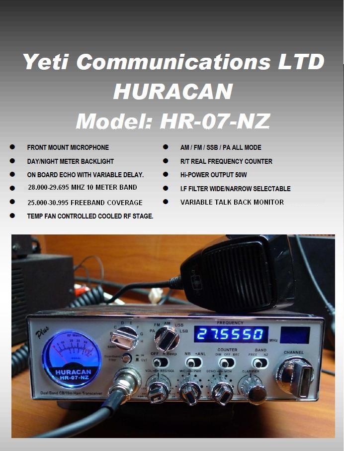
2 CONGRATULATIONS on your purchase of a HURACAN HR-07-NZ 10meter amateur radio. Your HURACAN HR-07-NZ transceiver radio is designed to provide trouble-free service and state of the art, high performance SSB communications. This radio has been designed with the SSB eenthusiast in mind incorporating new circuitry for increased SSB stability and improved SSB audio. To ensure proper performance, please read this manual thoroughly. BEFORE YOU OPERATE THE HR-07-NZ 10 METER AMATEUR RADIO In most countries a special licence is required to transmit on Amateur radio frequencies. Please ensure you have the required licence to operate this radio in the country you are using it. YeticomNZ is not responsible for any liabilities resulting from improper or unlicenced use of this equipment.
3 SPECIFICATIONS: HR-07-NZ 10 METER HF MOBILE TRANSCEIVER GENERAL Frequency Range: 10m Band MHz. Export export (5 bands 1mhz ea) NZ CB ch CB Band with channel readout Frequency Control: Phase Lock Loop (PLL) synthesizer. Frequency Tolerance: 0.005% Frequency Stability: 0.001% Operating Temp. Range: -22 F to +122 F. Microphone: Plug-in dynamic; with push-to-talk switch and coiled cord. Input Voltage: 13.8V DC nominal, 15.9V max 11.7V min. Current Drain: Tx : Rx : Size: Weight: Antenna Connector: Meter: AM full mod., 2.2A. Squelched, 0.3A. Maximum AF output, 0.7A 2-3/8 (H) x 7-7/8 (W) x 9-1/4 (D) 5 lbs. UHF, SO239 Illuminated ; indicates relative output power, received signal strength
4 TRANSMITTER Power Output (Max): AM 10w Carrier/50W PEP FM 50W SSB 50W PEP Modulation: AM = Class B Amplitude. FM = 20mV 1Khz Audio in Spurious Emission -60dB AF Modulation Response AM / FM Hz RECEIVER Circuit Type : Dual-Conversion Superheterodyne Intermediate Frequencies : 1st IF / SSB IF MHz 2nd IF khz Sensitivity : SSB μv at 10 db S + N/N AM μv at 10 db S + N/N FM μv at 12 db SINAD Selectivity : SSB khz (-6 db) / 8.5 khz (-60 db) AM / FM khz (-6 db) / 18 khz (-60 db) IF Frequencies AM/FM 1st Mhz, 2nd 455Khz.SSB Mhz Adjacent Channel Rejection : Better than 70 db IF Rejection : Better than 80 db for all frequencies Automatic Gain Control (AGC): Less than 10dB change in audio output for inputs From 10 V to 50,000 V. Squelch/ RF Gain Controls: 0.5 V=0dB Center Ref. adjustable +3dB to 40dB From threshold at rated sensitivity adjustable at Full mute 25 V at Max Gain, 1mV at Min. Gain. ANL+NB: RF Type + Clarifier Range : Fine: 1.5Khz Rx/Tx Audio Output: 4W Max., THD with 8 Ohms Load. Audio Response: Hz. External PA Output: 4W at 8 Ohms, disables internal speaker while plugged-in.
5 INSTALLATION 1. Contents Unpack and inspect your Huracan HR-07-NZ for missing or damaged components. Your Huracan HR-07-NZ includes the following items: Quantity Description 1 Huracan HR-07-NZ Transceiver 1 Dynamic Microphone 1 DC Power Cord with Inline Fuse 1 Mounting Bracket with Hardware 1 Mic Hanger with Hardware Set 1 Operating Manual 2. Microphone Hanger The microphone hanger may be attached to the side of the transceiver, or any other convenient location. Locate the mounting holes on the side of the transceiver. Use the provided screws to attach the microphone hanger either vertically or horizontally to the side of the transceiver. 3. Mounting When attaching the Huracan HR-07-NZ mounting bracket to the vehicle, choose a location that will provide easy access to all front panel controls and air circulation to the rear panel. When selecting a mounting location, make sure that there is ample space behind the unit for the cables. Do not pinch, or bend sharply, the power or antenna cables. Do not install the Huracan HR-07-NZ in any compartment that restricts airflow to the air vents under the transceiver or blocks the heat sink and do not install in a location that interferes with the safe operation of the vehicle. Attach the mounting bracket to the vehicle first then mount the Huracan HR-07-NZ to the bracket. If the rear panel is not accessible you may want to attach the power and antenna cable prior to mounting. Make sure that all of these components of your vehicle s electrical system are in good condition prior to installing the transceiver. CAUTION! VOLTAGE EXCEEDING 15 VDC WILL DAMAGE THE RADIO. MEASURE VOLTAGE AT BATTERY TERMINALS, WITH VEHICLE RUNNING, PRIOR TO INSTALLATION! Before making any electrical connections make sure the volume (VOL) control is in the OFF position. Connect the positive (+) red wire of the DC power cord to a positive 13.8 volt source at the vehicle fuse block. If connecting to the fuse block, it is recommended that a switched power source is used so that the power to the transceiver is is connected when the vehicle is off. This will eliminate the possibility of the transceiver draining the vehicle s battery. Connect the negative (-) black wire to a metal part of the vehicle s frame, or chassis ground. Make sure that this is a good ground connection.the Huracan HR-07- NZ power cord may also be connected directly to the battery. Connecting directly to the battery has several benefits, the first of which is to maximize RF output. Secondly, the battery is a very large capacitor and will help eliminate certain types of ambient and vehicle noise. If connecting directly to the vehicle s battery, additional power cable may be required.on runs of 8 feet or less use 14-gauge stranded wire. Use 12-gauge wire on longer runs. 4. Electrical Connections The Huracan HR-07-NZ is designed to work on any volt DC, negative ground, source. The condition of a vehicle s electrical system can affect operation. A low battery, worn generator/alternator, or poor voltage regulator will seriously impair the performance of the transceiver. Any of the above conditions could result in a high level of receiver noise generation or a substantial loss of the transmitter s RF output.
6 5. Antenna Connection: The transceiver will operate using any standard 50-ohm ground-plane, vertical, mobile whip, long wire or similar antenna. The antenna should be rated at 50 watts PEP minimum. A standard SO-239 type antenna connector is located on the rear panel of the Huracan HR-07-NZ. Connection is made using a PL-259 and high-grade coaxial cable (RG213, RG58A/U or Mini RG-8 is recommended). A ground-plane antenna provides greater coverage and is recommended for fixed station-to-mobile operation. For point-to-point fixed station operation, a directional beam antenna operates at greater distances even under adverse conditions. A non-directional antenna should be used in a mobile installation; a vertical whip is best suited for this purpose. The base loaded whip antenna normally provides effective communications. For greater range and more reliable operation, a full quarter wave whip may be used. Either of these antennas uses the metal vehicle body as a ground plane.once the antenna is mounted on the vehicle, route the coaxial cable so that it is not next to any power cables or vehicle cables. Connect the PL-259 to the antenna connector on the rear panel of the Huracan HR-07-NZ. Make sure that the cable does not interfere with the safe operation of the vehicle. 6. VSWR:(Requires external s.w.r meter) Before use, it is important to determine the antenna system s VSWR (voltage standing wave ratio). You will need a high quality SWR bridge (meter) to accurately tune your antenna system. First, make sure the SWR bridge is in good working order and is calibrated. To ensure your radio is performing properly the VSWR should never exceed 1.5 to 1. Never transmit on any antenna system where the VSWR exceeds 1.8 to 1.This will stress the output stage and could destroy the RF mosfets; this type of misuse and failure is not covered under warranty. Measure the VSWR at the center of the operating band. Tune the antenna (according to the antenna manufacturer s tuning instructions) so that the VSWR is as close to 1 to 1 at the center of the operating band. Next, measure the VSWR at the lowest and highest frequency of the transceiver. If the antenna has a wide enough frequency range and band-pass, he VSWR treadings should be below 1.5 to 1 across the entire operating band. If at the lower or upper end of the transceiver operating frequency, the VSWR measures more than 1.5 to 1, it is recommended that the antenna be retuned before operating on those frequencies.if you are experiencing unusual VSWR readings check for the following possible problems:) 1: Make sure that the antenna is installed properly and grounded. 2) Check all coaxial cable and connectors for defects and poor routing. 3) If testing a vehicle installation, make sure that all vehicle doors are closed when testing. 4) Do not test near or around large metal objects or buildings. TUNING THE ANTENNA FOR OPTIMUM SWR Since there is a such a wide vanity of base and mobile antennas, this section will strictly concern itself to the various types of mobile adjustable antennas. Because the antenna length is directly related to the channel frequency, it must be tuned to resonate optimally all Frequencies of the transceiver mhz requires a longer antenna than mhz, because it is lower in frequency. Due to the various methods of adjusting antennas for proper SWR we have chosen what we think is the optimum method: WARNING CONTINUOUS OPERATION OF THIS TRANSMITTER WITH GREATER THAN 4:1 VSWR ANTENNA MISMATCH MAY RESULT IN RF AMPLIFIER DAMAGE. A. Antenna with adjustment screws (set screws) 1. Start with the antenna extended and tighten the set screw tightly enough so that the antenna can be lightly tapped with your finger for easy adjustment. 2. Set your transceiver to a mid band frequency. Press PTT (push-to-talk) switch, and tap the antenna shorter. The SWR meter will show a lower reading each time the antenna is tapped. By continuing to shorten the antenna you will notice the SWR reading will reach a lowest point and than start to rising again, this means the optimum tuning being pressed for center operating frequency of your transceiver.
7 B. Antennas which must be cut to length 1. Follow the same procedure as above, but adjust the length by cutting in 1/8 inch increments until a good match is obtained. 2. Be very careful not to cut too much at one time, as once it is cut, it can no longer be lengthened. 3. The whip is easily cut by filing a notch all the way around and breaking the piece off with pliers. TIPS for Antenna Adjustment IF YOU ARE HAVING DIFFICULTIES IN ADJUSTING YOUR ANTENNA CHECK THE FOLLOWING: A. All doors of the vehicle must be closed when adjusting the antenna. B. Make sure the antenna base is grounded. C. Check your coaxial cable routing to make sure it is not pinched when routed into the car. D. Try a different location on your car, keeping in mind the radiation pattern you wish. E. Is the antenna perfectly vertical? F. Try a different location in your neighborhood. Stay away from large metal objects when adjusting, such as metal telephone or light poles, and fences, etc. ANTENNA A vertically polarized, quarter-wavelength whip antenna provides the most reliable operation and greatest range. Shorter, loaded-type whip antennas are more attractive, compact and adequate for applications where the maximum possible distance is not required.also, the loaded whips do not present the problems of height imposed by a full quarter wavelength whip. Mobile whip antennas utilize the metal body of the vehicle as a ground plane. When mounted at a corner of the vehicle they are slightly directional, in the direction of the body of the vehicle. For all practical purpose, however, the radiation pattern is nondirectional. The slight directional characteristic will be observed only at extreme distances. A standard antenna connector (type SO 239) is provided on the transceiver for easy connection to the standard PL-259 cable termination.if the transceiver is not mounted on a metal surface, it is necessary to run a separate ground wire from the unit to a good metal electrical ground in the vehicle. When installed in a boat, the transceiver will not operate at maximum efficiency without a ground plate, unless the vessel has a steel hull. Before installing the ransceiver in a boat, consult your dealer for information regarding an adequate grounding system and prevention of electrolysis between fittings in the hull and water. 7. Ignition Noise In certain vehicle installations, electrical noise or interference may be present in the receive audio of the transceiver. Typically the vehicle s ignition system or more specifically the alternator generates this noise. The Huracan HR-07-NZ is equipped with a noise blanker circuit that is designed to reduce, and in many instances eliminate, this electrical noise. In extreme cases, the noise blanker may not eliminate all the electrical noise. In such cases, an alternator/ ignition noise filter can be used Use of a mobile receiver at low signal levels is limited by the presence of electrical noise.the primary source of noise in automobile installations is from the generator and ignition system in the vehicle. Under most operating conditions, when signal level is adequate, the background noise does not present a serious problem. Even though the transceiver has ANL / NB controls, in some vehicles the ignition interference may be high enough to significantly effect the performance of the radio communications. The electrical noise may come from several sources. Many possibilities exist and variations between vehicles require different solutions to reduce the noise level. NOTE : WHEN EXTREMELY LOW LEVEL SIGNALS ARE BEING RECEIVED, THE TRANSCEIVER MAY BE OPERATED WITH VEHICLE ENGINE TURN OFF. THE UNIT REQUIRES VERY LITTLE CURRENT AND THEREFORE WILL NOT SIGNIFICANTLY DISCHARGE THE VEHICLE BATTERY.ON
. 2. VFO CONTROL: Rotate clockwise to increase frequency or counter-clockwise to decrease frequency.. 3.")
8 FRONT PANEL CONTROLS: 1. 2-DIGIT CHANNEL DISPLAY Displays operating channel does not display when in Free-band mode.will display when in 10 meter mode (see options list) or N.Z auto select mode (see control #7). 2. VFO CONTROL: Rotate clockwise to increase frequency or counter-clockwise to decrease frequency DIGIT FREQUENCY COUNTER Displays Receive/Transmit frequency in real time 4. MODE SWITCH: Selects desired operation modes. (PA): Public Address Mode. To operate PA, insert a public address speaker or horn into the PA jack on the rear panel of the transceiver. (FM) Frequency modulation (AM) Amitutre modulation (USB) Upper sideband (LSB) Lower sideband 5:BAND SWITCH: Selects band of operation see options list for frequency ranges
9 6: S/RF Meter: The meter indicates relative receive signal strength, RF output power, The meter features blue backlighting on receive and red backlighting on transmit. The meter features 2 scales Rx signal in 60dB max., and Tx max. 50W, the lower scale indicates relative signal strength (S units) for received transmissions. The top scale indicates the RF output power of the Huracan HR-07-NZ. O 7. Free-band/NZ40 Selector Auto Selector: When in the Freeband position the transceiver will work as per the options chart depending on the option the transceiver is setup for. In N.Z mode the channel display lights up and the radio will default to channel 35 (26.720mhz) which is the New Zealand LSB (lower sideband call channel 8. CLARIFIER: Transmit and receive tuning range /+1.5khz 9. MONI: All Mode Talk-back Monitor: All Mode Talk Back. is an independent talk back monitor. The AMT functions in all modes and allows the operator to monitor the transmitted audio of the Huracan HR-07-NZ.To increase the volume of the talk back rotate the control clockwise. To decrease rotate counter-clockwise. To turn off the talk back rotate the control completely counter-clockwise. 10. Echo On/Off-Delay: Echo Delay. Varies the amount of delay, or duration of the echo repetition. Rotate clockwise to increase the amount of delay and counter-clockwise to decrease. 11. R.F Power am/fm only: Variable RF Output Power. The transmitted power of the Huracan HR-07-NZ may be varied from 0 to 50 watts peak in Am/Fm modes. Rotate clockwise to increase RF output power. Rotate counter-clockwise to decrease RF output power.variable 1-10 watts carrier Am Mode /1-50 watts carrier Fm mode. 12. Microphone Gain. Microphone Gain. Increases or decreases the energy developed in the microphone amplifier circuit.the gain increases as the control is rotated clockwise. 13.Sq/Rf Gain control: Squelch and RF Gain combinded. Used to eliminate background or white noise when monitoring strong signals. To properly adjust the squelch circuit,start rotating the control slowly counter clockwise until the received white noise disappears. Adjusts the receiver sensitivity to both signals and background noise. This affects the distance at which a signal can be detected. Turning the control counterclockwise reduces the receiver sensitivity. This is particularly useful in areas where large volumes of traffic (signals) are present 14.ON/OFF: Turns the radio on and off. Rotate the control clockwise until it clicks to turn off. VOL: Volume. Adjusts the AF gain, or volume of the receive audio. Turn clockwise to increase and counter-clockwise to decrease.
10 15. Rodger Beep: Activates the end of transmission, or roger beep, tone. When activated a 1 khz tone will automatically transmit upon release of PTT switch.this notifies contacts that your transmission has ended and you are ready to receive their signal 16. Front Mounted Microphone input: Microphone wiring is as follows: Pin 1 : Ground Pin 2 : Microphone Audio Pin 3 : Transmit Pin 4 : Receive 17. Guard-Band Filter : (narrow/wide).i.f Filter an Switchable (narrow/standard) 6 pole I.F Filter with buffer.in normal use the filter switch would be in the out position (standard receive bandwidth) under bad band conditions or splatter from a couple of channels away from a over powered station or close station this can be put in to the depressed position (narrow) to help remove or suppress the offending signal. 18. NB-ANL SWITCH: Noise Blanker and Automatic Noise Limiter. In the NB position, only the noise blanker is ON. In the ANL position the automatic noise limiter are ON. The noise blanker circuit eliminates pulse type interference usually associated with automotive ignition systems. 19.DIM /OFF/BRITE: The 3 stage dimmer control allows you to select the proper illumination level for both the S/RF meter and blue LED displays. In the OFF position disables the frequency counter
11 REAR PANEL DETAILS: 1: 50 ohm antenna input SO239 Socket: 2: DC Power Input (13.8 volts dc) 3. Public Address (PA) Horn Jack A PA horn jack is located on the rear panel of the transceiver. The Huracan HR-07-NZ is designed to accept any standard PA horn for use with two-way transceivers. To operate in PA mode, please refer to the previous instructions. 4. External Speaker Jack An external speaker jack is located on the rear panel of the transceiver. The Huracan HR-07-NZ is designed to accept any standard 8 ohm external speaker for use with two way transceivers. IMPORTANT NOTE FOR USE EXTERNAL SPEAKERR1 The external speaker jack EXT. SPK. on the rear panel, is used for remote receiver monitoring. The external speaker should have 8 ohms impedance and be able to handle at least 4 watts. When the external speaker is plugged in, the internal speaker is disconnected. IT HAS NO AUDIO OUTPUT FROM THIS JACK, WHILE SELECTED TO P.A.MODE OPERATION.
12 USING YOUR RADIO FOR THE FIRST TIME : PROCEDURE TO RECEIVE 1. Turn unit on by tuning ON / OFF VOLUME control clockwise. 2. Set the VOLUME for a comfortable listening level. 3. Set the MODE switch to the desire mode. 4. Listen to the background noise from the speaker. Turn the SQ/RFG Gain control slowly counter clockwise until the noise JUST disappears (no signal should be present). Leave the control at this setting. The SQL/RF Gain. Is now properly adjusted. The receiver will remain quiet until a signal is actually received Do not advance the control too far, or some of the weaker signals will not be heard. 5. Set the VFO selector and band switchs to the desired frequency. 6. Set the SQ/RF gain control fully clockwise for maximum RF gain if required (defeats squelch In this setting.) 7. Select the desired frequency of transmission. 8. Set the MIC. GAIN control fully clockwise. 9. Set R.F power control to power level required. 10. If the frequency is clear, depress the PTT switch on the mic., and speak in a normal voice. PRESS-TO-TALK MICROPHONE Press the switch and the transmitter is activated, the receiver and transmitter are controlled by the PTT switch on the microphone., release switch to receive. When transmitting, hold the microphone two inches from the mouth and speak clearly in a normal voice ALTERANIVE MICROPHONES: The Radio come complete with low impedance (500 ohms) dynamic microphone. For best results, the user should select a low-impedance dynamic type microphone or a transistorized microphone. Transistorized type microphones have a low output impedance characteristic.the microphones must be provided with a four-lead cable. The audio conductor and its shielded lead comprise two of the leads. The fourth lead is for receive control, and the third is for transmit control. The microphone should provide the functions shown in FIG. 1 of the microphone wiring schematic.if the microphone to be used is provided with per-cut leads, they must be received as follows. Cut leads so that they extend 7/16 beyond the plastic insulating jacket of the microphone cable. All leads should be cut to the same length. Strip the ends of each wire 1/8 and tin the exposed wire.before beginning the actual wiring read carefully, the circuit and wiring information provided with the microphone you select. Use the minimum head required in soldering the connections. Keep the exposed wire lengths to a minimum to avoid shorting when the microphone plug is reassembled.
13 MICROPHONE PLUG REASSEMBLING: 1. Remove the retaining screw. 2. Unscrew the housing from the pin receptacle body. 3. Loosen the two cable clamp retainer screws. 4. Feed the microphone cable though the housing, knurled ring and washer shown in FIG The wires must now be soldered to the pins as indicated in the FIG. 1, wiring tables. If a vise or clamping tool is available, it should be used to hold the pin receptacle body during the soldering operation, so that both hands are free to perform the soldering. If a vise or clamping tool is not available, the pin receptacle body can beheld in a stationary position by inserting it into the microphone jack of the front panel. The numbers of the pins of the microphone plug are shown in FIG. 2, as viewed from the back of the plug. Before soldering the wire to the pins, per-tin the wire receptacle of each pin of the plug. Be sure that the housing and the knurled ring of FIG. 3 are pushed back onto the microphone cable before starting to solder. If the washer is not captive to the pin receptacle body, make sure that it is placed on the threaded portion of the pin receptacle body before soldering.if the microphone jack is used to hold the pin receptacle during the soldering operation,best results are obtained when the connections to pins 1 and 3 are made first and then the connections to pins 2, 4 and 5. Use a minimum amount of solder and be careful to prevent excessive solder accumulation on pins, which could cause a short between the pin and the microphone plug housing. 6. When all soldering connections to the pins of the microphone plug are complete, push the knurled ring and the housing forward and screw the housing onto the threaded portion of the pin receptacle body. Note the location of the screw clearance hole in the plug housing with respect to the threaded hole in the pin receptacle body.when the housing is completely threaded into the pin receptacle body, a final fraction of a turn either clockwise or counter clockwise may be required to align the screw hole with the threaded hole in the pin receptacle body. When these are aligned, the retaining screw is then screwed into the place to secure the housing to the pin receptacle body 7. The two cable clamp retainer screws should now be tightened to secure the housing to the microphone cord. If the cutting directions have been carefully followed, the cable clamp should secure to the insulating jacket of the microphone cable.upon completion of the microphone plug wiring, connect and secure the microphone plug in the transceiver.
14
15 Receiving SSB Signals There are four types of signals presently used for communications in an Amateur band: AM, FM, USB and LSB. When the MODE switch on your unit is placed in the AM position, only standard double sideband and in FM position, only frequency deviation, full carrier signals will be detected. An SSB signal may be recognized while in the AM or FM mode by its characteristic Donald Duck sound and the inability of the AM or FM detector to produce an intelligible output, the USB and LSB modes will detect upper sideband and lower sideband respectively, and standard AM signals SSB reception differs from standard AM reception in that SSB receiver does not require a carrier or opposite sideband to produce an intelligible signal. A signal-sideband transmitted signal consists only of the upper or the lower sideband and no carrier is transmitted. The elimination of the carrier from the AM signal helps to eliminate the biggest cause of whistles and tones heard on channels which make even moderately strong AM signals unreadable.the reduction in channel space required also helps in the receiver because only half of the noise and interference can be received with 100% of the SSB signal. An SSB signal may be received only when the listening receiver is functioning in the same mode. In other words, an upper sideband signal (USB) may be made intelligible only if the receiver is functioning in the USB position. If the lower sideband (LSB) signal is heard when the receiver is in the USB mode, no amount of tuning will make the signal intelligible. The reason for this may be understood if you consider that when modulation is applied to the transmitter s microphone in the USB mode, the transmitter s output frequency is increased whereas in the LSB mode the transmitter s output frequency is decreased. The result in listening the receiver is that when the MODE switch is in the proper position either USB or LSB. A true reproduction of signal tone of modulation will result, and if the tone is increased in frequency such as a low pitched whistle will caused a high-pitched whistle you will hear the increase in the output tone of the receiver. If the incorrect mode is selected, an increase in tone of a whistle applied to the transmitter will cause a decrease in the resultant tone from the receiver. Thus when a voice is used in place of a whistle or tone, in the proper listening mode the voice will be received correctly whereas in the incorrect mode, the voice will be translated backwards and cannot be made intelligible by the voice lock control. When listening to an AM transmission, a correct sideband is heard in either mode since both upper and lower sideband is received. Once the desired SSB mode has been selected, frequency adjustment may be necessary in order to make the incoming signal intelligible, the CLARIFIER control allows the operator to vary frequency above and below the exact-center frequency of the received signal. If the sound of the incoming signal is high or low pitched, adjust the operation of the CLARIFIER. Consider it as performing the same function as a phonograph speed control. When the speed is set to high, voices will be high-pitched and if set too low, voices will be low-pitched. Also, there is only one correct speed that will make a particular record produce the same sound that was recorded. If the record is played on a turntable that rotated in the wrong direction (opposite sideband) no amount of speed control (CLARIFIER) will produce an intelligible sound. An AM signal received while listening in one of the SSB modes will produce a steady tone (carrier) in addition to the intelligence, unless the SSB receiver tuned to exactly the same frequency by the Clarifier control. For simplicity it is recommended that the AM modes be used to listen to AM signals.
16 OPTIONS LIST Introduction: The HURACAN HR-07-NZ is programmed for the 10 Meter Amateur Band out of the box, and covers a range of MHz in 5 khz steps standard. The frequency range can be extended for Export Use in 6 Band segments OF 1MHZ each containing 200 Channels (200 X 5KHZ STEPS= 1MHZ). 10 Meter Only Mode: The default setting from the factory covers 8 bands between MHz MHz. The jumper setting for this is JP1, JP2, JP3,JP4 = all jumpers OFF (N.Z 40 channel auto select mode can be used in this mode) Free-band Mode: This mode is pre-set to 6 Bands (1MHZ each 200x 5khz steps )between MHz MHz. The jumper setting for this mode is JP1 = ON, JP2= OFF,JP3 = ON JP4 = OFF. (N.Z 40 channel auto select mode can be used in this mode) Programming Notes: * Replace the Metal Cover on the Channel Board after programming to reduce receiver noise.

17
SUPERSTAR TABLE OF CONTENTS AM/FM/USB/LSB/CW AMATEUR MOBILE TRANSCEIVER WITH BUILT-IN FREQUENCY COUNTER OWNER S MANUAL
 SUPERSTAR TABLE OF CONTENTS AM/FM/USB/LSB/CW AMATEUR MOBILE TRANSCEIVER WITH BUILT-IN FREQUENCY COUNTER PAGE CHAPTER 1 Specifications............................................... 2 CHAPTER 2 Installation.................................................
DX 33HML. Full Channel AM/FM Mobile Transceiver OWNER S MANUAL. Printed In Malaysia AT H PD000802
 DX 33HML Full Channel AM/FM Mobile Transceiver Printed In Malaysia AT3601014H PD000802 OWNER S MANUAL TABLE OF CONTENTS Page Specification.................................... 2 Installation Location.....................................
DX 33HP. 10 Meter Amateur Mobile Transceiver OWNER S MANUAL. Download this Manual Free of Charge at
 DX 33HP SIG 1 3 TX PWR 5 7 9+30dB POWER HI NB/ANL MED LO HI LO BAND ECHO RX/TX VOL SQ MIC RF FM PA AM D/A E/B F/C ECHO TIME BAND 10 Meter Amateur Mobile Transceiver Download this Manual Free of Charge
CON NEX HP. OWNER'S MANUAL Full Channel AM/FM Amateur Mobile Transceiver TABLE OF CONTENTS TUNING THE ANTENNA FOR OPTIMUM S.W.R..
 TABLE OF CONTENTS PAGE SPECIFICATIONS... 2 INSTALLATION... 3 LOCATION... 3 CON NEX - 4300HP MOUNTING THE RADIO... 3 IGNITION NOISE INTERFERENCE... 4 ANTENNA... 4 TUNING THE ANTENNA FOR OPTIMUM S.W.R..
DX 29HP. 10 Meter Amateur Mobile Transceiver OWNER S MANUAL PRINTED IN MALAYSIA PN:A412308CNA
 DX 29HP 10 Meter Amateur Mobile Transceiver OWNER S MANUAL PRINTED IN MALAYSIA PN:A412308CNA TABLE OF CONTENTS Page Specification.................................... 2 Installation Location.....................................
DX 66V OWNER S MANUAL. Full Channel AM/FM Mobile Transceiver Built in Frequency Counter with Roger Beep
 WARRANTY This radio is covered by a two year limited parts and labor warranty. Limited means that we will repair problems caused by factory defects or normal use at no charge. Before returning a radio
OWNER'S MANUAL Channels All-Mode AM/FM/USB/LSB Built in Frequency Counter Mobile Transceiver with Roger Beep
 SUPER STAR 7QOODX OWNER'S MANUAL 3360 Channels All-Mode AM/FM/USB/LSB Built in Frequency Counter Mobile Transceiver with Roger Beep TABLE OF CONTENTS Page Specifications... 2 Installation Location... 4
AM/FM 10 METER MOBILE AMATEUR TRANSCEIVER OPERATING MANUAL
 AM/FM 10 METER MOBILE AMATEUR TRANSCEIVER OPERATING MANUAL INTRODUCTION Congratulations on your purchase of a Magnum S-6 AM/FM 10 meter transceiver. Your Magnum S-6 is designed to provide years of enjoyment
DX 99V OWNER S MANUAL. Full Channel AM/FM/SSB Mobile Built in Frequency Counter with Roger Beep
 WARRANTY This radio is covered by a two year limited parts and labor warranty. Limited means that we will repair problems caused by factory defects or normal use at no charge. Before returning a radio
Installation... 3 Installing The Radio... 3 Ignition Noise Interference... 4 Antenna... 4 External Speaker... 4 Public Address...
 TABLE OF CONTENTS CHAPTER 1 Specifications.............................................. 2 PAGE BIG RIG SERIES S 1 MOD PW R 20 0 3 SW R 40 1 5 5 60 1.5 7 10 2 9 20 80 3 30 +20 40 50 +40 100% MAX db +60
DX 73V OWNER S MANUAL FULL FEATURED AM/FM MOBILE TRANSCEIVER. WARRANTY This radio is covered by a two year limited parts and labor warranty.
 WARRANTY This radio is covered by a two year limited parts and labor warranty. Limited means that we will repair problems caused by factory defects or normal use at no charge. Before returning a radio
Downloaded from
 TABLE OF CONTENTS Installation... 2 Location... 2 Mounting the Connection... 2 Ignition Noise Interference... 2 Antenna... 2 Tuning the Antenna for Optimum SWR... 3 External Speaker... 4 Replacing fuse...
You must activate your warranty Do not call to register your radio.
 INTRODUCTION Congratulations on your purchase of a Stryker 10 meter mobile amateur transceiver. Your Stryker is designed to provide years of enjoyment and trouble-free service.there are many features and
Zeon PDF Driver Trial
 401 W. 35th Street, Suite B National City, CA 91950 (800)446-5778. FAX( 619)426-3788 Email : rci@rangerusa.com http : //www.rangerusa.com Printed In Malaysia AT6960A11A PD000619 TR-936 SOLID STATE CITIZENS
Zeon PDF Driver Trial
 401 W. 35th Street, Suite B National City, CA 91950 (800)446-5778. FAX( 619)426-3788 Email : rci@rangerusa.com http : //www.rangerusa.com Printed In Malaysia AT6960A11B PD000619 TR-966 SOLID STATE CITIZENS
DX 93T OWNER S MANUAL. 10 Meter Amateur Mobile Transceiver With Built-in Frequency Counter & StarLite Face Plate TABLE OF CONTENTS CHAPTER 1 CHAPTER 2
 PAGE CHAPTER 1 Specifications.............................................. 2 Twin Turbine S 1 PW R 3 20 0 SW R 40 1 5 5 60 1.5 7 10 2 9 20 80 3 30 +20 40 50 DX 93T +40 100% MAX db +60 DX 93T B A SW R
DX AM FM SSB CW PA Amateur Base Station Transceiver OWNER S MANUAL RX / TX 2 4 POWER NF CHANNEL MODE RF POWER OFF CAL OFF OFF CALIBRATE
 1 2 3 6 4050 ULA 6070 TI 80 90 100 9 DX 2517 2517 RX / TX 0 2 4 SWR WATTS SET 81012 22 1 010 3 2030 5 MOD 7 ON dbover 9 SIGNAL +20 +40+60 PA FM AM USB LSB CW POWER ON SWR NB / ANL R.BEEP +10KHz NF CHANNEL
AM/FM/SSB/CW 12 & 10 METER MOBILE AMATEUR TRANSCEIVER OWNER S MANUAL
 AM/FM/SSB/CW 12 & 10 METER MOBILE AMATEUR TRANSCEIVER OWNER S MANUAL TABLE OF CONTENTS Warranty...2 Introduction...3 Installation... 4-5 Front Panel Controls... 6-8 Microphone...8 Menu Settings... 9-11
OWNERS MANUAL. Solid State Citizens Band AM Mobile Transceiver With Blue Illuminated Lite TABLE OF CONTENTS CHAPTER 1 CHAPTER 2 CHAPTER 3 PAGE
 TABLE OF CONTENTS PAGE CHAPTER 1 Specifications................................................ 2 DX-939 Solid State Citizens Band AM Mobile Transceiver With Blue Illuminated Lite OWNERS MANUAL CHAPTER
TABLE OF CONTENTS. Magnum International PO Box 445 Issaquah, WA 98027
 OPERATING MANUAL TABLE OF CONTENTS Limited Warranty... 2 Introduction... 3 Installation...3-4 Front Panel Controls and Functions...4-7 Other Features... 7 Specifications... 8 LIMITED WARRANTY Magnum International
RCI-6300F25/150. Owner's Manual. AM/FM Amateur Transceiver With Built-in Frequency Counter. Table of Contents. Downloaded from
 Table of Contents RCI-6300F25/150 AM/FM Amateur Transceiver With Built-in Frequency Counter PAGE Chapter 1 Specifications...... 2 Chapter 2 Installation...... 3 Installing the Radio... 3 Ignition Noise
DELUXE 18CHANNEL SSB/AM CB TRANSCEIVER OWNER'S GUIDE
 DELUXE 18CHANNEL SSB/AM CB TRANSCEIVER OWNER'S GUIDE General Description The Bush Ranger is a combination transmitter and receiver designed for use in the Australian 27 MHz Citizens radio service. It is
PPR Channel AM Mobile CB Radio OWNER S MANUAL CONTENS. PAGE Specifications... 2
 CONTENS PGE Specifications................................... 2 PPR-125 40 Channel M Mobile CB Radio Installation..................................... 3 Location...................................... 3
DX 979 OWNERS MANUAL. AM / SSB Two Way Citizens Band Mobile Transceiver With StarLite Face Plate TABLE OF CONTENTS CHAPTER 1 CHAPTER 2 CHAPTER
 TABLE OF CONTENTS DX 979 CHAPTER 1 Specifications................................................ 2 PAGE CHAPTER 2 Installation.................................................. 3 Installing The Radio..........................................
DX 929 OWNERS MANUAL. Two Way Citizens Band Mobile Transceiver With StarLite Face Plate TABLE OF CONTENTS CHAPTER 1 CHAPTER 2 CHAPTER PAGE
 TABLE OF CONTENTS DX 929 CHAPTER 1 Specifications................................................ 2 PAGE CHAPTER 2 Installation.................................................. 3 Installing The Radio..........................................
18-CHANNEL MOBILE CB TRANSCEIVER MODEL CB-845
 18-CHANNEL MOBILE CB TRANSCEIVER MODEL CB-845 INSTRUCTION HANDBOOK RAll JEFFERSOn CITIZEN BAND RADIO MESSAGE TO THE OWNER CONGRATULATIONS! As the new owner of Ray Jefferson Model CB-845 CB Mobile Transceiver,
Operation Manual. SlJPER ST AR Channel Mobile 5-Mode Transceiver -----~- --:.. KTSS200NXX ,, I
 Operation Manual!.,, SlJPER ST AR 2000 200 Channel Mobile 5-Mode Transceiver -----~- --:.. KTSS200NXX General Description l Frequency/Channel Chart The Super Star -2000 is a combination transmitter-receiver
CITIZENS BAND SSB/AM 2-WAY MOBILE RADIO
 OPERATING INSTRUCTIONS FOR YOUR 40 CHANNEL CITIZENS BAND SSB/AM 2-WAY MOBILE RADIO Model 148 GTL Nothing comes close to a Cobra PRINTED IN CHINA 2002 COBRA ELECTRONICS CORPORATION 480-046-P 6500 WEST CORTLAND
OPTIMA MK3 OWNERS MANUAL & USER GUIDE Mhz 50W All Mode HF Mobile Transceiver. (November 2012 production)
") OPTIMA MK3 OWNERS MANUAL & USER GUIDE 24.500 29.999 Mhz 50W All Mode HF Mobile Transceiver (November 2012 production) REV 1.8 Copyright November 2012 by YeticomNZ. All rights reserved. Downloaded from
OPTIMA MK3 OWNERS MANUAL & USER GUIDE 24.500 29.999 Mhz 50W All Mode HF Mobile Transceiver (November 2012 production) REV 1.8 Copyright November 2012 by YeticomNZ. All rights reserved. Downloaded from
DX 2547 AM/ SSB Two Way Citizen Band Base Station Transceiver OWNER S MANUAL
 DX 2547 POWER S 1 3 20% 5 7 40% 9 60% +20 80% 100% +40 db +60 NORMAL 9 19 TALKBACK MOD PWR 0 SWR 1 3 1.5 6 2 9 AM / SSB Base Station CB Radio 3 12 15 MAX CHANNEL GNF R.B. PA USB AM LSB ANL NB OFF DX 2547
Midland 248XL I NSTRUCTION GUI DE
 Midland 248XL I NSTRUCTION GUI DE INDEX Introduction...2 Function and location of the controls...3 Installation...7 Power supply...7 Installing an antenna...7 How to use your Midland 248XL...8 Frequency
USER MANUAL ENGLISH 1
 USER MANUAL ENGLISH 1 2 3 TABLE OF CONTENT Introduction...4 Limited Warranty...5 Installation...6 Front Panel Controls...7 Rear Panel Controls...8 European CB Regulations...9 Technical specifications...10
VvV MODEL-309 OWNER'S MANUAL. 40 channel CB Transceiver. Professional Quality And Performance Standards Advanced Circuitry With PLL Synthesis
 VvV MODEL-309 OWNER'S MANUAL 40 channel CB Transceiver Professional Quality And Performance Standards Advanced Circuitry With PLL Synthesis GENERAL INSTRUCTIONS Your model is an all solid-state SSB/AM
.TABLE OF CONTENTS Introduction... 2 Installation Front Panel Controls and Functions Other Features... 8 Specifications...
 .TABLE OF CONTENTS Introduction... 2 Installation... 3-4 Front Panel Controls and Functions... 4-8 Other Features... 8 Specifications... 10 European Warranty Conditions Your distributor, where You have
Introduction Pag. 1. Function and location of the controls Pag. 2. Installation Pag. 3. Power supply Pag. 3. Installing an antenna Pag.
 ALAN 121 INDEX Introduction Pag. 1 E N G L I S H Function and location of the controls Pag. 2 Installation Pag. 3 Power supply Pag. 3 Installing an antenna Pag. 4 How to operate with your transceiver Pag.
Frequency Coverage MHz RF Power Output 30W SSB / 9W AM/ 30W FM Dual Finals on Heat Sink Modes AM, FM, USB, LSB Microprocessor
 MAGNUM M-257 30W AM/ /FM/SSB 10--11 Meterr Mobile Trranscei ivverr n Prri iiccee: : US$ 250..00 eexx ssttoocckk JJaakkaarrttaa (Arrrri ( iivvi iinngg 2 d weeeekk iinn i Maarrcchh) ) SPECIFICATIONS Frequency
User Manual. Specifications...3. Control and Operation Microphone...8. Installation...9. Installation of Main Unit...9
 Contents Specifications...3 Control and Operation...4-7 Microphone...8 Installation...9 Installation of Main Unit...9 Antenna Installation...9 Operational test...9 Frequency Bands Table...10 Frequency
HR MHZ AM-FM AMATEUR RADIO HF TRANSCEIVER OWNER'S MANUAL. Content of the packaging
 HR-2800 28 MHZ AM-FM AMATEUR RADIO HF TRANSCEIVER OWNER'S MANUAL NOTICE! It is recommended to carefully read this owner s manual before using the product. This will also help to prevent illegal use of
5001z. 40 Channel Citizen Band Mobile Radio Owner s Manual.
 5001z 40 Channel Citizen Band Mobile Radio Owner s Manual Table of Contents Welcome to the World of Midland Electronics Major 5001z Features Installation Location Mechanical Mounting Power Wiring Mounting
UltraForce Amateur 10 m Transceiver OPERATING MANUAL 2005 Edition
 UltraForce Amateur 10 m Transceiver OPERATING MANUAL 2005 Edition ALAN Electronics GmbH www.albrecht-online.de www.alan-germany.de 1 .TABLE OF CONTENTS Introduction...... 2 Installation... 3-4 Front Panel
Installation and operating accessories furnished with your Midland CB:
 1 Your 40 channel CB represents the state of the art in high tech engineering. This unit is not only a full feature CB transceiver but incorporates a high performance 10 channel NOAA weather bureau VHF
4W MOBILE CB TRANSCEIVER INSTRUCTION MANUAL
 4W MOBILE CB TRANSCEIVER INSTRUCTION MANUAL www.ttikorea.co.kr CONTENTS 1. Introduction 2. Supplied Accessories 3. Installation 4. Transceiver Controls and Functions 1) Microphone Jack 2) LCD Display 3)
Elmer Session Hand Out for 3/3/11 de W6WTI. Some Common Controls Found On Amateur Radio Transceivers. (From ARRL web site tutorial)
") Elmer Session Hand Out for 3/3/11 de W6WTI Some Common Controls Found On Amateur Radio Transceivers. (From ARRL web site tutorial) The placement of the controls may vary from manufacturer to manufacturer
Elmer Session Hand Out for 3/3/11 de W6WTI Some Common Controls Found On Amateur Radio Transceivers. (From ARRL web site tutorial) The placement of the controls may vary from manufacturer to manufacturer
MFJ-219/219N 440 MHz UHF SWR Analyzer TABLE OF CONTENTS
 MFJ-219/219N 440 MHz UHF SWR Analyzer TABLE OF CONTENTS Introduction...2 Powering The MFJ-219/219N...3 Battery Installation...3 Operation Of The MFJ-219/219N...4 SWR and the MFJ-219/219N...4 Measuring
Cross-Connect Interface
 Cross-Connect Interface User Manual Document #: 050-015-0036R01 November 2006 TASC Systems Inc. Langley, BC Canada Cross-Connect System User Manual Preface This document describes the installation, commissioning
SUBELEMENT T4. Amateur radio practices and station set up. 2 Exam Questions - 2 Groups
 SUBELEMENT T4 Amateur radio practices and station set up 2 Exam Questions - 2 Groups 1 T4A Station setup: connecting microphones; reducing unwanted emissions; power source; connecting a computer; RF grounding;
Downloaded from
 Owner s Manual AM/FM 40 CHANNEL & TONE SQUELCH CITIZENS BAND TRANSCEIVER Downloaded from www.cbradio.nl Characteristics of C-Five 1. Improved audio sensitivity by adopting audio compressing and decompressing
AE 497 W (25-30 W-Version)
") User Manual AE 497 W (25-30 W-Version) 10-Meter Amateur Radio Base Station Legal notes and general information This amateur radio base station complies to the minimum requirements of the EU directives
User Manual AE 497 W (25-30 W-Version) 10-Meter Amateur Radio Base Station Legal notes and general information This amateur radio base station complies to the minimum requirements of the EU directives
Please read before using this equipment
 Please read before using this equipment DRAGON MODEL : SS-485H OWNER'S MANUAL 10 METER AM/FM/SSB MOBILE RADIO FEATURES Your SS-485H 10 Meter Amateur Transceiver is a two-way 28 MHz radio for use in your
WARNING WELCOME TO USE RESET
 WARNING Please install the antenna (connect to the location B on the back panel of the radio) and set the SWR (Standing Wave Ratio) before transmitting. Failure to do so may result in destruction of the
The amazing evolution of the 706 series
 The amazing evolution of the 706 series The IC-706MKIIG carries on the 706 series tradition of base station performance and features in a mobile reg-sized package. Building on this legacy, frequency coverage
Vectronics VC-300D DIGITAL BARGRAPH ANTENNA TUNER
 Vectronics VC-300D DIGITAL BARGRAPH ANTENNA TUNER FEATURES The Vectronics VC-300D Antenna Tuner optimizes the performance of your antenna and transmitter, receiver, or transceiver by providing adjustable
CONTENTS FUNCTIONS & FEATURES...1 STANDARD ACCESSORIES...2
 CONTENTS FUNCTIONS & FEATURES...1 STANDARD ACCESSORIES...2 OPTIONA ACCESSORIES...2 INSTAATION...2 GETTING ACQUAINTED...6 OW TO USE YOUR RADIO...8 SIDE SWITCES...9 ERROR CODE...10 SPECIFICATIONS...11 FUNCTIONS
Model 1791 VHF Radio User's Manual
 Model 79 VHF Radio User's Manual ALL WEATHER INC 65 NATIONAL DRIVE SACRAMENTO, CA 95834 WWW.ALWEATHERINC.COM 79 VHF RADIO USER'S MANUAL CONTENTS INTRODUCTION... Description... Transmitter Module... Power
4W MOBILE CB TRANSCEIVER INSTRUCTION MANUAL
 4W MOBILE CB TRANSCEIVER INSTRUCTION MANUAL www.ttikorea.co.kr CONTENTS 1. Introduction 2. Supplied Accessories 3. Installation 4. Transceiver Controls and Functions 1) Channel Selector 2) Dual Watch 3)
Technician Licensing Class. Lesson 4. presented by the Arlington Radio Public Service Club Arlington County, Virginia
 Technician Licensing Class Lesson 4 presented by the Arlington Radio Public Service Club Arlington County, Virginia 1 Quiz Sub elements T6 & T7 2 Good Engineering Practice Sub element T8 3 A Basic Station
AMPLIFIERS BI BI BI BI4400.4
 LIMITED WARRANTY Bass Inferno warrants any products purchased in the U.S.A. from an authorized Bass Inferno dealer. All products are warranted to be free from defects in material and workmanship under
200GTL ALIGNMENT REVISION: 1.0 BURKE MODEL: 200GTL REVISION: 1.2 DATE: 02/14/06. Total Pages: 6 pages. Page:1 print date: 9/23/09
 ALIGNMENT PROCEDURE MODEL: 200GTL REVISION: 1.2 DATE: 02/14/06 PREPARED BY: BURKE Total Pages: 6 pages Page:1 print date: 9/23/09 1 TEST CONDITION: 200GTL ALIGNMENT INSTRUCTION 1.0. TEST TEMPERTAURE: 77
ALM473 DUAL MONO \ STEREO AUDIO LEVEL MASTER OPERATION MANUAL IB
 ALM473 DUAL MONO \ STEREO AUDIO LEVEL MASTER OPERATION MANUAL IB6408-01 TABLE OF CONTENTS GENERAL DESCRIPTION 2 INSTALLATION 2,3,4 CONNECTION AND SETUP 4,5,6,7 FUNCTIONAL DESCRIPTION 8,9 MAINTENANCE 9
OWNER'S MANUAL. Full Channel AM/FM/SSB Mobile Built in Frequency Counter AM/FM 10W SSB 21W with Roger Beep
 OWNER'S MANUAL Full Channel AM/FM/SSB Mobile Built in Frequency Counter AM/FM 10W SSB 21W with Roger Beep TABLE OF CONTENTS Specifications Installation Location... 4 Mounting the Connection... 4 Ignition
LBI-31564A. Mobile Communications. DELTA - SX MHz RADIO COMBINATIONS (NEGATIVE GROUND ONLY) Maintenance Manual
 Maintenance Manual") A Mobile Communications DELTA - SX 136-174 MHz RADIO COMBINATIONS (NEGATIVE GROUND ONLY) Maintenance Manual TABLE OF CONTENTS MILITARY AND SYSTEM SPECIFICATIONS................................. 2-3 COMBINATION
A Mobile Communications DELTA - SX 136-174 MHz RADIO COMBINATIONS (NEGATIVE GROUND ONLY) Maintenance Manual TABLE OF CONTENTS MILITARY AND SYSTEM SPECIFICATIONS................................. 2-3 COMBINATION
MFJ-969 Versa Tuner II Instruction Manual
 MFJ-969 Versa Tuner II Instruction Manual General Information The MFJ-969 is a 300 watt RF output power antenna tuner that will match any transmitter or transceiver to virtually any antenna. Peak or average
Owner s Manual. Printed in China U01UT389ZZA(0)
") 680 Owner s Manual Printed in China U01UT389ZZA(0) Contents SAFETY NOTICE...3 Unpacking...3 Description...3 Emergency Operation...4 Controls and Functions...4 Installation...6 MOBILE STATION INSTALLATION...
680 Owner s Manual Printed in China U01UT389ZZA(0) Contents SAFETY NOTICE...3 Unpacking...3 Description...3 Emergency Operation...4 Controls and Functions...4 Installation...6 MOBILE STATION INSTALLATION...
AMPLIFIERS. Bi2200Tx Bi4200Fx. Bi1400Mx Bi2400Mx Bi3000Mx
 LIMITED WARRANTY Bass Inferno warrants any products purchased in the U.S.A. from an authorized Bass Inferno dealer. All products are warranted to be free from defects in material and workmanship under
Downloaded from
 Downloaded from www.cbradio.nl WARNING Please install the antenna (connect to the location B in the back panel of the radio) and set the SWR (Standing Wave Ratio) before transmitting. Otherwise it may
TWS 16 HT UHF wireless system. user manual
 TWS 16 HT UHF wireless system user manual Musikhaus Thomann e.k. Treppendorf 30 96138 Burgebrach Germany Telephone: +49 (0) 9546 9223-66 E-mail: info@thomann.de Internet: www.thomann.de 30.04.2012 Table
FT-897 Alignment. Local Oscillator Adjustment. PLL Adjustment
 FT-897 Local Oscillator Adjustment Reference Frequency Adjustment a. Connect a frequency counter to TP1032. b. Adjust the trimmer capacitor (TC5001) for 67.875000MHz ±5Hz on the frequency counter. c. Connect
PROAUDIO AMPLIFIERS BI2400PRO BI3400PRO
 LIMITED WARRANTY Bass Inferno warrants any products purchased in the U.S.A. from an authorized Bass Inferno dealer. All products are warranted to be free from defects in material and workmanship under
FMR622S DUAL NARROW BAND SLIDING DE-EMPHASIS DEMODULATOR INSTRUCTION BOOK IB
 FMR622S DUAL NARROW BAND SLIDING DE-EMPHASIS DEMODULATOR INSTRUCTION BOOK IB 1222-22 TABLE OF CONTENTS SECTION 1.0 INTRODUCTION 2.0 INSTALLATION & OPERATING INSTRUCTIONS 3.0 SPECIFICATIONS 4.0 FUNCTIONAL
Electrophone. Model TX Channel 27MHz AM/SSB Deluxe Mobile 2-way CB. Instruction Manual. lectrephone AWSSI3 TRANSCEIVER MODEL IX 560
 Electrophone Model TX-560 40-Channel 27MHz AM/SSB Deluxe Mobile 2-way CB lectrephone AWSSI3 TRANSCEIVER MODEL IX 560 Instruction Manual General description Thank you for your confidence in selecting an
hallicrafters PERFORMANCE SPECIFICATIONS MODEL: SR-2000 LATEST REVISION: 18 JAN 66 Code ident # Specification #
 hallicrafters PERFORMANCE SPECIFICATIONS MODEL: SR-2000 LATEST REVISION: 18 JAN 66 Code ident # 26916 Specification # 093-002154 I. GENERAL A. Power input 117V 50-60 cycles from a source capable of delivering
LnR Precision, Inc. 107 East Central Avenue, Asheboro, NC
 LD5 CW/SSB QRP Transceiver Quick guide manual Description: At the development base of the digital signal processing unit, an algorithm is embedded for IQ processing of the channels with phase suppression
RITEK RIT for Collins KWM-2/2A 10/01/2002
 RITEK RIT for Collins KWM-2/2A 10/01/2002 The RITEK RIT (receiver incremental tuning) control was developed for KWM-2/2A in 1992 to "clarify" received signals differing from the transmit frequency indicated
DC Instruction Manual. Professional FM Transceiver
 DC-1074 Professional FM Transceiver Instruction Manual Use of the citizen band radio service is licensed in Australia by ACMA Radiocommunications (Citizen Band Radio Stations) Class Licence and in New
Introduction. Understanding Power Ratings. Peak Reading SWR/Wattmeter
 Introduction The MFJ-962D is a "T" network roller inductor tuner with built-in antenna switching, RF power and SWR metering and a 1:1 balun. The largest amplifiers that can safely be used include the Heathkit
QUICK REFERENCE GUIDE
 QUICK REFERENCE GUIDE Installation 1. Install a ground system for DC noise suppression and RFI suppression 2. Install your DC power supply 3. Install lightning protection. This will help protect more than
EDACS WALL MOUNT STATION. Maintenance Manual. Mobile Communications LBI-31838A TABLE OF CONTENTS
 A Mobile Communications EDACS WALL MOUNT STATION TABLE OF CONTENTS SYSTEM BOARD & REGULATOR BOARD.......... LBI-31892 KEY/DISPLAY BOARD MAINTENANCE MANUAL.... LBI-31940 Maintenance Manual Printed in U.S.A.
When you check the list of features offered by the PLMRA220,PLMRA420 you ll know you made the right choice with a Pyle Marine amplifier.
 congratulations... on your purchase of a Pyle Marine Series amplifier. This amplifier extends the Pyle tradition into a totally new series of amps, designed from the ground up to deliver the power, performance
Technician Licensing Class. Antennas
 Technician Licensing Class Antennas Antennas A simple dipole mounted so the conductor is parallel to the Earth's surface is a horizontally polarized antenna. T9A3 Polarization is referenced to the Earth
Mobile RF Linear Amplifier
 Features High Reliability Design +13.8VDC Operation All Mode (AM, FM, SSB) 10-Meter Amateur Band Coverage Temperature Tracking Class-AB Bias High Output Power / Low Harmonic Content Quad MRF454 Configuration
WARNING: DO NOT PROCEED WITHOUT READING THIS PAGE.
 WARNING: DO NOT PROCEED WITHOUT READING THIS PAGE. The B-2530-G produces at least 300 watts of VHF R.F. power and is not to be taken lightly. Severe R.W. burns can be sustained at this power level! Power
MFJ-208 VHF SWR Analyzer
 MFJ-208 VHF SWR Analyzer Thank you for purchasing the MFJ-208 VHF SWR Analyzer. The MFJ-208 gives you a direct readout of your antenna's SWR without the need for formulas or indirect readings. The MFJ-
LDG TW-1 Talking Wattmeter
 LDG TW-1 Talking Wattmeter LDG Electronics 1445 Parran Road, PO Box 48 St. Leonard MD 20685-2903 USA Phone: 410-586-2177 Fax: 410-586-8475 ldg@ldgelectronics.com www.ldgelectronics.com 1 LDG TW-1 Talking
IC-F7000. Advanced selective call and ALE make HF communication easier than ever!
 Page 1 of 5 HF TRANSCEIVER IC-F7000 Advanced selective call and ALE make HF communication easier than ever! The IC-F7000 is an HF land mobile transceiver especially designed forlong distance communications.
R-400A Telemetry Receiver For Law Enforcement Tracking
 R-400A Telemetry Receiver For Law Enforcement Tracking COVERS THE ENTIRE 216.000-219.999MHz BAND IN 1kHz STEPS FOR QUICK AND ACCURATE FREQUENCY SELECTION SUPER SELECTIVE 8 POLE SSB CRYSTAL FILTER FOR GREATER
WARNING: DO NOT PROCEED WITHOUT READING THIS PAGE.
 WARNING: DO NOT PROCEED WITHOUT READING THIS PAGE. The B-1030-G produces at least 300 watts of VHF R.F. power and is not to be taken lightly. Severe R.W. burns can be sustained at this power level! Power
RMV25 / RMV50 RMU25 / RMU45
 RMV25 / RMV50 RMU25 / RMU45 Owner's Manual TABLE OF CONTENTS INTRODUCTION... 3 FCC Requirements... 3 SAFETY WARNING INFORMATION... 3 CONTROLS and INDICATORS... 5 FRONT PANEL... 5 LCD Icons and Indicators...
user s manual PLA2170 PLA2270 PLA2370 PLA2470 PLA2570 PLA4170 PLA4270 PLA4370 limited warranty policy Brooklyn, NY 11204
 limited warranty policy a m p l i f i e r s All Pyle products are carefully constructed and thoroughly tested before shipment. Products purchased in the USA are warranted to be free of defects in material
MFJ-949E. tuner antenowy skrzynka antenowa. Instrukcja obsługi. importer:
 Instrukcja obsługi MFJ-949E tuner antenowy skrzynka antenowa importer: PRO-FIT Centrum Radiokomunikacji InRadio ul. Puszkina 80 92-516 Łódź tel: 42 649 28 28 e-mail: biuro@inradio.pl www.inradio.pl MFJ-949E
LBI-4938C. Mobile Communications MASTR II POWER AMPLIFIER MODELS 4EF4A1,2,3. Printed in U.S.A. Maintenance Manual
 C Mobile Communications MASTR II POWER AMPLIFIER MODELS 4EF4A1,2,3 Printed in U.S.A. Maintenance Manual TABLE OF CONTENTS DESCRIPTION.................................................... 1 CIRCUIT ANALYSIS.................................................
Single Channel Radio Mic System USER MANUAL. WMU-116-H (Hand Held) WMU-116-B (Belt Pack) Single Channel Radio Mic System
 WMU-116-B (Belt Pack) Single Channel Radio Mic System") Single Channel Radio Mic System USER MANUAL WMU-116-H (Hand Held) WMU-116-B (Belt Pack) Single Channel Radio Mic System Welcome Thank you for choosing Hill Audio for your sound system. To make sure that
Single Channel Radio Mic System USER MANUAL WMU-116-H (Hand Held) WMU-116-B (Belt Pack) Single Channel Radio Mic System Welcome Thank you for choosing Hill Audio for your sound system. To make sure that
PRO505XL Professional Mobile CB Radio
 PRO505XL Professional Mobile CB Radio 2016 Uniden America Corp. Printed in Vietnam Irving, Texas U01UT386ZZA(1) INTRODUCTION Welcome to the world of Citizens Band radio communications. Your Uniden radio
VECTRONICS HFT-1500 Digital Bargraph Antenna Tuner
 Table of Contents FEATURES... 1 SPECIFICATIONS... 1 FRONT PANEL INDICATORS AND CONTROLS... 1 CONTROLS... 1 REAR PANEL CONNECTORS... 1 OTHER... 2 CONTOLS / CONNECTORS... 2 FRONT PANEL FUNCTIONS... 2 REAR
SETUP and OPERATING MANUAL ADVANCED MULTI-CHANNEL VEHICLE INTERCOM SYSTEM (AMCVIS)
") SETUP and OPERATING MANUAL Sept 23, 2010 Rev D ADVANCED MULTI-CHANNEL VEHICLE INTERCOM SYSTEM (AMCVIS) with DIGITAL CREW CONTROL and RADIO BRIDGING The AMCVIS was designed, manufactured and is supported
SETUP and OPERATING MANUAL Sept 23, 2010 Rev D ADVANCED MULTI-CHANNEL VEHICLE INTERCOM SYSTEM (AMCVIS) with DIGITAL CREW CONTROL and RADIO BRIDGING The AMCVIS was designed, manufactured and is supported
GRAND STRAND AMATEUR RADIO CLUB
 The GRAND STRAND AMATEUR RADIO CLUB (GSARC) Myrtle Beach SC is offering used amateur related equipment for sale. Written bids may be submitted to the GSARC up to Friday, November 23 rd, 2018. Only currently
MA6004 MA6002 MARINE AUDIO POWER AMPLIFIER OWNER S MANUAL. The Official Brand of Live Music.
 MA6004 MA6002 MARINE AUDIO POWER AMPLIFIER OWNER S MANUAL The Official Brand of Live Music. INSTALLATION THANK YOU for purchasing a JBL marine amplifier. In order that we may better serve you should you
ENCORE 200 VHF Bass Wireless Microphone System
 ENCORE 200 VHF Bass Wireless Microphone System Nady Wireless Systems are type accepted under FCC rules parts 90, 74 and 15. The device complies with RSS-210 of Industry & Science Canada. Operation is subject
TWS 16 PT UHF wireless system. user manual
 TWS 16 PT UHF wireless system user manual Musikhaus Thomann Thomann GmbH Hans-Thomann-Straße 1 96138 Burgebrach Germany Telephone: +49 (0) 9546 9223-0 E-mail: info@thomann.de Internet: www.thomann.de 17.11.2015,
damage. expiration date. also include a check or money order for $18.00 for return shipping, and R.A. number
 limited warranty policy a m p l i f i e r s All Pyle products are carefully constructed and thoroughly tested before shipment. Products purchased in the USA are warranted to be free of defects in material
Definitions of Technical Terms
 Definitions of Technical Terms Terms Ammeter Amperes, Amps Band Capacitor Carrier Squelch Diode Dipole Definitions How is an ammeter usually connected = In series with the circuit What instrument is used