Ultrafast Coherent Optical Signal Processing using Stabilized Optical Frequency Combs from Modelocked
|
|
|
- Primrose Griffin
- 5 years ago
- Views:
Transcription

1 Ultrafast Coherent Optical Signal Processing using Stabilized Optical Frequency Combs from Modelocked Diode Lasers Peter J. Delfyett CREOL, The College of Optics and Photonics, University of Central Florida, Orlando, Florida University of California Santa Barbara, CA December 5, 2012
2 Outline Motivation Background Key Technologies Stabilized Optical Frequency Combs Arcsine Phase & Linear Intensity Modulators w/ Comb Filter Direct Phase Detection (w/o external local oscillator) w/ Comb Filter Applications Arbitrary Waveform Measurements Arbitrary Waveform Generation Pattern Recognition using Matched Filtering Techniques Summary and Conclusions 2
3 Motivation Why Diode Based Fiber Lasers? Diode lasers are small (100 s microns), electrically efficient (>70%), wavelength agile (300 nm to >10 microns via bandgap engineering). Robust, no moving / mechanical parts Broad bandwidth potential for large tuning bandwidth. Operates over very broad temperature ranges. Cost effective, direct electrically (battery) pumped. Can engineer the cavity Q to be >> than conventional cavities Potential for photonic integrated circuits, e.g., electronics, lasers, modulators & detectors full functioning optoelectronic systems on a chip computing & signal processing at the speed of light! 3


4 Applications Enabled By Optical Frequency Combs Sensing, Detecting and Response Synthetic Aperture Imaging Advanced Waveform Generation/Measurement Ultrawideband Communications 4
5 Power Power Amplitude Power Power Power Harmonic Modelocked Lasers Schematic Representations Time Interleaved Pulse Trains T C =L/c Time Overlaid Pulse Trains T= 1/f ML e it 2 Time Overlaid Supermode Spectra c/l 5 f ML Optical Frequency Time e i e i2 Amplitude Power Time Interleaved Supermode Spectra E() E(-) E(-2) f ML c/l Optical Frequency e it2t Time A 1 =1 A 2 =1 A 3 =0.5
6 Watts/Hz db/hz Intensity Intensity Intensity of Optical Pulse Train Optical Pulse Train Intensity (a) Intensity of Optical Pulse Train Optical Pulse Train Intensity (b) Time Optical Spectrum Optical of of Pulse Pulse Train Train (c) Time 20 RF Power Spectrum of Pulse Train RF Power Spectrum of Pulse Train (d) Supermode Noise Spurs Frequency Frequency
7 7 Low Noise Modelocked Diode Lasers Via Stabilization of the Frequency Comb
8 Power Power Fundamentally Modelocked Lasers c/l RF Power Spectrum Optical Frequency Frequency T=100 ps Time RF Power Spectrum Corner Frequency f mod =c/l =10 GHz 8 L 1 pulse in the cavity SOA ~ System Noise Floor Log Frequency Corner frequency moves to large offset frequencies w/ short cavities
9 Power Power Harmonically Modelocked Lasers 10GHz Coupled Modes c/l RF Power Spectrum Optical Frequency T=100 ps Time RF Power Spectrum Corner Frequency Supermodes f mod =Nc/L =10 GHz 9 L N pulses in the cavity N Independent longitudinal mode groups SOA ~ Example: Ring Laser Mode Spacing=10 MHz f mod = 10 GHz N=1000 System Noise Floor Log Frequency
10 Power Power Power Power Harmonic Modelocking & Supermode Suppression 10GHz 10GHz Optical Frequency T=100 psec Optical Frequency T=100 psec Time Time L T=100 psec L Supermode Suppression Filter =10GHz SOA SOA F mod =nc/l 10 = 10GHz ~ F mod =nc/l =10GHz ~
11 Transmission Transmission Nested Optical Cavities I T T2 i 0.0 I2 1 Rexp idi i i 1 R2 exp id R 1 =R 2 =90%; T 1 =T 2 =10%; FSR 2 / FSR 1 = (a) Frequency (b) Frequency Cavity Product Identical to R=99%; T=1% 11
12 Harmonically Mode-locked Lasers & Supermode Suppression Laser cavity DC DCF DCF PC IM PC FL PC etalon GHz SOA PC I FL SOA: semiconductor optical amplifier PC: polarization controller IM: intensity modulator I: isolator DCF: dispersion compensating fiber FL: fiber launcher Modulation rate Etalon transmission Mode spacing The etalon free spectral range must match the mode-locking rate. Laser cavity modes must coincide with etalon transmission peaks. ν 12
13 Setup Ultra-low noise osc. at GHz DC Output PDH Loop PC IM I OPS PID PC SOA VOD PC PM I PC Free Space Optics Cir PBS PC 640 MHz PD Laser Cavity FPE PC O PS I: isolator SOA: semiconductor optical amplifier OPS: Optical phase shifter PD: photodetector PC: polarization controller IM: intensity modulator PBS: polarization beam splitter FPE: Fabry-Perot etalon PID: PID controller PM: phase modulator Cir : optical circulator OPS: Optical Phase Shifter VOD: Variable Optical Delay DCF: Dispersion Comp. Fiber PDH: Pound Drever Hall 13


14 Actively MLL with intracavity 1000 Finesse etalon Laser is constructed on a optical breadboard and thermally and acoustically isolated with foam insulation. 14
15 Actively MLL with intracavity 1000 Finesse etalon Sampling scope and autocorrelation traces The pulses are compressed to 1.1 ps autocorrelation FWHM by using a dual grating compressor. 15
16 Actively MLL with intracavity 1000 Finesse etalon Optical spectrum High Resolution Comb Line The 10 db spectral width of the optical spectrum is ~8.3nm. The comb line has a ~50dB signal-to-noise ratio 16
17 Actively MLL with intracavity 1000 Finesse etalon Timing jitter and amplitude noise: Integrated timing jitter (1 Hz 100 MHz) is ~3fs and up to Nyquist it is 14fs. 17 Integrated amplitude noise (1 Hz 100 MHz) is 230ppm. Note the overall dynamic range of the measurement 10 16
 The linewidth of the laser with")
18 Amplitude (dbm) Actively MLL with intracavity 1000 Finesse etalon Optical linewidth/stability measurement. High Resolution Spectrum Analyzer MLL CW laser PC OSA RFSA Stability CW laser Stabilized Frequency Comb lines Frequency (GHz) The linewidth of the laser with the 1000 Finesse etalon was measured as ~ 500 Hz (Note the relative ratio of the carrier frequency to the linewidth ~ ) Stability of 150 khz over 30 sec (NB: Measurements are limited by the CW laser linewidth & stability) 18
19 Low Noise Modelocked Diode Lasers The Effect of Intracavity Power 19
 1 A 2 A 3")
 W. Loh, et. al. IEEE J. Quant. Electron., v. 47, p.")
20 Gain (db) SCOW Amplifier SCOWA Slab-Coupled Optical Waveguide Amplifier P out (dbm) 1 A 2 A 3 A 4 A 20 J. J. Plant, et. al. IEEE Phot. Tech. Lett., v. 17, p.735 (2005) W. Loh, et. al. IEEE J. Quant. Electron., v. 47, p. 66 (2011)
 PC PBS CIR 500 MHz PD Pound-Drever-Hall Loop Optical Path Electrical Path CIR: Circulator DBM: Double Balanced Mixer FPE: Fabry-Perot Etalon ISO: Isolator LPF: Low-Pass Filter OC: Output")
21 Etalon stabilized HMLL Experimental setup Ultra-low noise oscillator GHz Laser Output PC PC IM ISO PZT SCOWA VOD PID PC ISO PM LPF OC PC PS PC DBM FPE (FSR = GHz) PC PBS CIR 500 MHz PD Pound-Drever-Hall Loop Optical Path Electrical Path CIR: Circulator DBM: Double Balanced Mixer FPE: Fabry-Perot Etalon ISO: Isolator LPF: Low-Pass Filter OC: Output Coupler (Variable) PC: Polarization controller PD: Photodetector PID: Proportional-Integral-Differential Controller PM: Phase Modulator PS: Phase Shifter PZT: Piezoelectric Transducer (Fiber Stretcher) SOA: Semiconductor Optical Amplifier (SCOWA) VOD: Variable Optical Delay 21 Long fiber cavity provides narrow resonances Fabry-Pérot Etalon provides wide mode spacing Pound-Drever-Hall loop locks both cavities An ultra-low noise oscillator is used to drive the laser I. Ozdur, et. al., PTL, v. 22, pp (2010) F. Quinlan, et. al., Opt. Express 14, (2006)
 0-10 -20-30 ~60 db Radio-Frequency Spectrum Span: 100 MHz Res. BW: 3 khz -40-50 -60-70 -80-90 -100-110 10.24 10.26 10.28 10.30 10.")
22 Relative Power (db) L(f) (dbc/hz) Integrated Timing Jitter (fs) Power (dbm) Power (dbm) Time (35 s) Etalon-based Ultralow-noise Frequency Comb Source Optical Spectrum Wavelength (nm) ~60 db Radio-Frequency Spectrum Span: 100 MHz Res. BW: 3 khz Frequency (GHz) High-Resolution Optical Spectrum Span: 1 GHz Res. BW: 1 MHz ~60 db Frequency (100 MHz/div) Optical Frequency Stability Measurement Etalonstabilized laser ( GHz) Etalonstabilized laser ( GHz) Real-time Spectrum Analyzer Single sideband phase noise spectrum Residual Phase Noise Noise Floor Poseidon Oscillator Absolute Noise k 10k 100k 1M 10M 100M Frequency Offset (Hz) Real-time spectrogram Frequency Offset (MHz)
23 AC Trace (a.u.) Relative Power (db) Oscillator characterization Intensity Autocorrelation RF Power Spectrum Compressed AC Transform Limited AC p = 930 fs Span: 100 MHz Res. BW: 3 khz Delay (ps) Frequency (GHz) Pulses are compressible to close to the transform limit Photodetected RF tone has >90 db dynamic range 23
")
24 Optical Power (dbm) Amplification Output power and spectral characteristics Directly from MLL I=4A, P out =214 mw I=4A, P out =320 mw Wavelength (nm) 24
25 L(f) (dbc/hz) Integrated Jitter (fs) Timing Jitter SSB Phase Noise Comparison (ii) (iii) (iv) (i) All-anomalous Cav. and SCOWA 10 (ii) Disp. Comp. Cav. (iii) All-anomalous and Covega (iv) Poseidon Oscillator 8 Noise Floor -110 (i) k 10k 100k 1M 10M 100M Frequency Offset (Hz) 0 25
26 Outline Motivation Background Key Technologies Stabilized Optical Frequency Combs Arcsine Phase & Linear Intensity Modulators w/ Comb Filter Direct Phase Detection (w/o external local oscillator) w/ Comb Filter Applications Arbitrary Waveform Measurements Arbitrary Waveform Generation Pattern Recognition using Matched Filtering Techniques High Precision Laser Radar w/ Unambiguous Ranging & Velocimetry Summary and Conclusions 26
27 General Ideas for OFC Modulation Desirable Modulator Qualities for real time OFC applications: - Linear modulation transfer function - Large modulation bandwidth - Low Insertion Loss (negative..?) - Low V π - Good power handling capability - Comb filtering, tunable, arrays Current methods of modulating light intensity: Direct modulation of diode driving current Frequency chirp External modulation: Electro-optic modulators (EOM) Nonlinear modulation transfer function and Relatively high V π Electro-absorption modulators (EAM) Poor optical power handling, High insertion loss and Sensitive to temperature and wavelength Proposed concept for OFC modulation: Injection locking a resonant cavity w/ gain (VCSEL) arcsine phase modulation NB: Linear intensity modulator in an interferometric configuration 27


28 Injection-Locked Resonant Cavity as an Arcsine Phase Modulator ω 1 Master laser Adler s equation*: ω 0 Slave laser φ ω π 2 ω 1 ω 0 φ ω = sin 1 ω ω m ω = ω 1 ω 0 2ω m : locking range ω 0 ω = ω 1 ω 0 ω 1 π 2 *A. E. Siegman, Lasers, 1986 Locking range 28
29 Resonant Cavity Interferometric Modulator Comparison to a Conventional MZ Modulator Resonant cavity linear modulator I in sin ( ( )) f(t) ~ 1 f t I 0,ω 1 f ( t) 1 Iout Iin ( ) 2 T(V) Phase response Stable locking range Calculate SFDR I out π/2 V Electro-optic Mach-Zehnder modulator T(V) I in f(t) ~ 0 V ( t) / V 1 cos( ) I out I in ( ) 2 I out V 29
30 Phase Modulation & Filtering -Channel selection concept Ch. 1 Ch. 2 VCSEL Bias T DC current= I 1 Ch. N Comb Modulated Output AC Modulation; f 1, P(f) ω= ω + f 1 I(ω) 0 Filtering & Modulation f 1 f Ch. 1 DC=I 1 Ch. 2 DC=I 2 ω RF Spectrum Optical Spectrum 30
31 Frequency (THz) Phase Modulation & Filtering -Channel selection concept Ch. 1 Ch. 2 VCSEL Bias T DC current= I 2 Ch. N Comb Modulated Output AC Modulation; f 2 P(f) ω= ω + f 2 Filtering & Modulation I(ω) 0 f 2 f Frequency vs. Current Measurement Linear fit Ch. 1 DC=I 1 Ch. 2 DC=I 2 ω RF spectrum Slope ~ 50 GHz/mA Optical Spectrum DC Driving Current (ma) 31
32 Static phase (radian) Power (dbm) Fundamental & intermodulation power (dbm) CW laser Iso Linear Modulator Experimental Results GHz 1 GHz VOA + PZT PC RF Bias Tee VCSEL CIR PC PID I DC 50/50 90/10 PD VCSEL: vertical cavity surface emitting laser Iso: isolator VOA: variable optical attenuator PC: polarization controller PZT: piezoelectric transducer PD: photo detector PID: proportional-integrated-differential controller CIR: circulator OSA: optical spectrum analyzer RFSA: RF spectrum analyzer EDFA High-res OSA PD RFSA SFDR = 130 db.hz 2/3 Fundamental IM3 Noise floor Spur free dynamic range of ~130 db.hz 2/3 Very low V π of ~ 2.6 mv Multi-gigahertz bandwidth (~ 5 GHz) Possible gain Measurement 0 Fit DC Current Deviation (ma) RF Input (dbm) db Frequency (GHz) 32
33 Outline Motivation Background Key Technologies Stabilized Optical Frequency Combs Arcsine Phase & Linear Intensity Modulators w/ Comb Filter Direct Phase Detection (w/o external local oscillator) w/ Comb Filter Applications Arbitrary Waveform Measurements Arbitrary Waveform Generation Pattern Recognition using Matched Filtering Techniques High Precision Laser Radar w/ Unambiguous Ranging & Velocimetry Summary and Conclusions 33
34 Direct demodulation of phase modulated signals Operating principle: Detecting light-induced changes in the forward voltage of an optically injection locked VCSEL operating above threshold. Physical origin: Voltage change is due to the change in the carrier density in the active region of the VCSEL when driven by an external phase modulated light. I (ω) & ψ(ω) V(ω) ω l ω o ω h ω Δω Locking range N. Hoghooghi, et. al, IEEE Photonics Technology Letters, 22(20), pp ,
35 Channel filtering concept Ch. 1 Ch. 2 VCSEL Bias T AC voltage DC voltage Ch. N I(ω) π π 0 0 π π 0 0 Phase detector P(f) Ch. 1 f mod =f 1 Ch. 2 f mod =f 2 ω f 1 f 2 f Optical spectrum RF spectrum 35
36 Demodulation & channel filtering with an injection-locked VCSEL Nx1 combiner Power (db) Ch.2 (0.9 GHz) Ch.1 (0.8 GHz) Optical path Electrical path RFSA CW laser 12.5 GHz IM WDM filter PC PC PM PM PC CIR RF Bias T DC VCSEL PC PM OSA Ch.3 (1 GHz) 0-10 VCSEL PC: polarization controller PM: phase modulator IM: intensity modulator CIR: circulator OSA: optical spectrum analyzer RFSA: RF spectrum analyzer Ch.3 Ch.2 Ch Wavelength (nm) 36
37 Power (dbm) Power (dbm) Power (dbm) Power (db) Power (db) Power (db) Optical spectra Experimental results of three channel system Ch.1 Ch.2 Ch Wavelength (nm) Wavelength (nm) Wavelength (nm) Corresponding detected RF spectra RBW 30 khz Span 270 MHz SNR ~ 60 dbc/hz -65 RBW 30 khz -70 Span 270 MHz SNR ~ 62 dbc/hz RBW 30 khz Span 270 MHz SNR ~ 60 dbc/hz Frequency (MHz) Frequency (MHz) Frequency (MHz) First demonstration of direct demodulation and channel filtering of phase modulated signals with SNR of 60 dbc/hz. 37
38 Linear Modulator Concept for Pulsed Light - A resonant cavity (Fabry-Perot) with multiple resonances, injection locked by a modelocked laser as the frequency comb. - By simultaneous modulation of the period combs, one imparts arcsine phase modulation on each injected comb. Received RF signal 1/f rep Fabry-Perot Laser FSR=f rep Optical Frequency MLL FP FP resonances Corresponding phase responses Injected comb lines from the MLL Imparted phase on each injected combs 38
39 Outline Motivation Background Key Technologies Stabilized Optical Frequency Combs Arcsine Phase & Linear Intensity Modulators w/ Comb Filter Direct Phase Detection (w/o external local oscillator) w/ Comb Filter Applications Arbitrary Waveform Measurements Arbitrary Waveform Generation Pattern Recognition using Matched Filtering Techniques Summary and Conclusions 39
40 Multi-heterodyne detection of frequency combs Motivation Mode-locked laser f A W D M WDM f AM AM Extremely complex arbitrary waveforms can be generated with frequency combs Instantaneous bandwidth in the order of several THz PM PM f W D M A dt ~ 1/BW BW f 40
41 Optical Power Spectral Density RF Power Spectral Density Multi-heterodyne Detection of Frequency Combs (Optical Sampling) (a) (b) f rep PLL Comb Source Comb Source f (1) rep D LPF RFSA Diagnostics Oscilloscope δ f (2) rep ν Photodetection δ ν Δ Δ+δ Δ+2δ Δ f (1) rep ½f (1) rep f 2f (1) rep f (2) rep 41 Each pair of comb-lines generates a unique RF beat-note The RF beat-note retains the relative phase between the comb-lines
42 Multi-heterodyne detection of frequency combs Experimental results Mode-locked laser combs Power (5 db/div.) Power (dbm) Power (dbm) Optical spectra First two sets of RF beat notes Wavelength (nm) Effective repetition rate detuning ~600 khz Total Optical BW ~ 17nm ~2.12THz Compression factor ~ 17,000x Frequency (MHz) 10 GHz spacing optical comb is mapped into a 600 khz spacing RF comb Frequency (MHz) 42
43 Pulse Combs Time Domain Experimental Results (10 GHz & 250 MHz) Voltage [mv] Amplitude (a.u.) Time domain waveform Stretched Dispersion Normal 0-10 Direct output time [s] 0 5 Time (μs) Compressed Anomalous As the optical pulse is stretched and compressed, the RF waveform does the same Optical waveform is mapped to RF waveform 43
44 Phase Modulated CW Combs Experimental Results ~10 GHz CW Laser Phase Modulator RFSA Erbium Fiber Mode-locked Laser Real time oscilloscope 44

 Amplitud")
45 Instantaneous Frequency (MHz) Amplitude (mv) Amplitude (a.u.) Phase () Multi-heterodyne detection of frequency combs Experimental results Phase modulation combs Time domain waveform Time (s) Instantaneous frequency 60 Fourier transform Frequency (MHz) Time (s) The optical waveform chirp is mapped to the RF waveform Spectral phase information can be retrieved 45
46 Outline Motivation Background Key Technologies Stabilized Optical Frequency Combs Arcsine Phase & Linear Intensity Modulators w/ Comb Filter Direct Phase Detection (w/o external local oscillator) w/ Comb Filter Applications Arbitrary Waveform Measurements Arbitrary Waveform Generation Pattern Recognition using Matched Filtering Techniques Summary and Conclusions 46
47 Intensity Intensity Intensity Optical DACs using Frequency Comb Filtering Static Approach T 1/T Time Frequency T 1/T Time Frequency 47
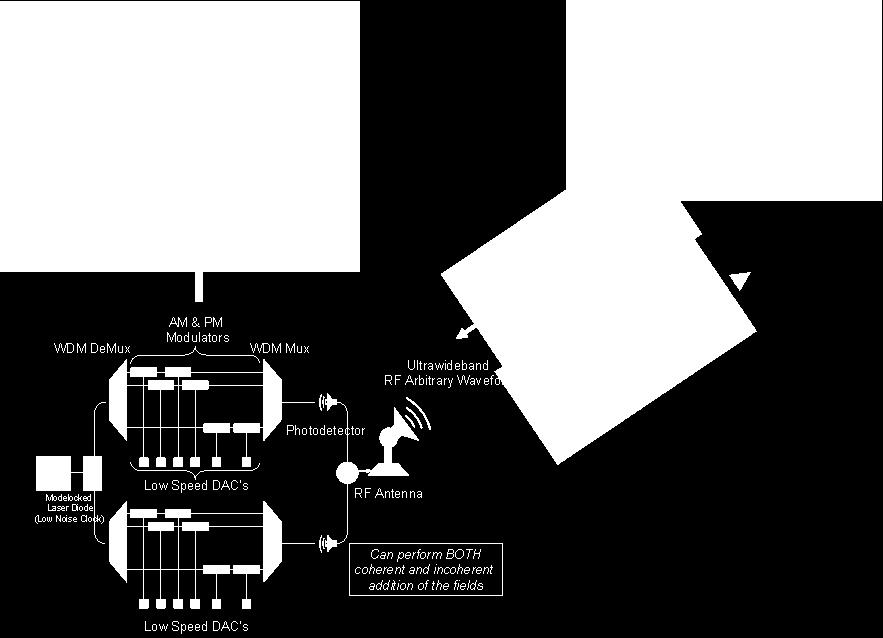
48 Optical DACs using Frequency Comb Filtering Dynamic Approach WDM DeMux Modulator Array Maximum Modulation Rate F~ WDM Mux Modelocked Comb Generator N Combs Comb Spacing Ultra-Pure CW channels Modulated CW Channels Arbitrary Waveform Instantaneous Bandwidth Nx Temporal Gate 48 Pulse Shaping at the Highest Possible Spectral Resolution Challenges: Some waveforms require phase modulation well beyond 2
49 A Novel Concept for Ultra-High-Speed Optical Pulse Shaping Phase / Amplitude > 10 6 increase in the refresh rate!!! Our novel idea is different than the conventional approaches in 4 ways: Instead of manipulating the existing optical combs, we regenerate the optical combs with the desired amplitudes and phases The refresh rate is limited by the modulation speed of the VCSELs (10s of GHz) The channel count can easily be scaled by going from 1-D array into 2-D array geometry Simultaneous modulation and amplification 49 49


50 High-speed Reconfigurable Optical Arbitrary Waveform Generation Four optical comblines, independently modulated and coherently combined Wavelength demux and mux pair 6.25 GHz channel spacing Each modulator Injection-locked VCSEL with current modulation 50
 1538.90 1538.95 1539.00 1539.05 1539.10 1539.15 1539.20 1539.25 1539.30 1539.35 1539.40 1539.45 1539.")
51 Power (dbm) Voltage (mv) Experimental Setup Optical Frequency Comb Source Generated by modulation of CW laser Adjust DC bias voltages, RF phases and amplitudes to achieve five combs of 0 equal power ps ~30 ps Wavelength (nm) Time (ns)

52 Experimental Setup Demux, Mux Specifications Essex Hyperfine WDM filters Fiber-pigtailed input and outputs Channel spacing of 6.25 GHz Adjacent channel isolation ~ 22 db Gaussian shaped passband 3 db channel bandwidth ~ 3.5 GHz Mux, Demux are a matched pair 52
 100m 0-20 Time (s) 5.120n 6.400n Photodetected RF spectrum -40-60 53 0.00 6.25G 12.50G 18.75G 25.")
53 Power (dbm) Voltage (V) Voltage (V) Intensity Profile of Rapidly Updated Optical Waveforms VCSEL RF frequency (MHz) VCSEL RF frequency (MHz) m 100m 0 200m n 2.56n 3.84n 5.12n 6.40n 7.68n 8.96n Time (s) 100m 0-20 Time (s) 5.120n 6.400n Photodetected RF spectrum G 12.50G 18.75G 25.00G Frequency (Hz)
 194.747 194.754 194.760 194.766 194.")
54 Power (dbm) Intensity Profile of Rapidly Updated Optical Waveforms VCSEL RF frequency (MHz) Optical Spectrum -10 VCSEL 3 IL trc -20 VCSE Freq.( RF (d Frequency (THz)
55 Reconfigurable Cross Connect Switch / Pulse Shaping Code Reconfiguration DC 3 DC 1 DC 4 DC 2 DC 1 DC 3 DC 2 DC 4 Information from any wavelength can be arbitrarily switched between channelsat rates approaching channel spacing. 100 times faster that the existing MEMS technology. 55
56 Outline Motivation Background Key Technologies Stabilized Optical Frequency Combs Arcsine Phase & Linear Intensity Modulators w/ Comb Filter Direct Phase Detection (w/o external local oscillator) w/ Comb Filter Applications Arbitrary Waveform Measurements Arbitrary Waveform Generation Pattern Recognition using Matched Filtering Techniques Summary and Conclusions 56
57 Matched Filtering using OFC s 57

58 Comparison to OCDMA Optical Code Division Multiple Access (OCDMA) Spectral modulation, temporal spread Decoding: Needs non-linear optical thresholding because of slow response time of photodetectors Heritage and Weiner, IEEE JSTQE, 2007 Coherent detection technique is linear Requires less optical power Jiang et al., IEEE PTL,
59 Complete Experimental Setup 59
60 Interference using Orthogonal Codes Using orthogonal codes gives best contrast between different binary sequences λ PD 0,0,0, λ 0,0,0, λ Code A Code B Code C Code D λ PD 0,π,0,π λ 0,0,0, λ Differential signal - PD λ Differential signal - PD λ 60
61 Summary of Results, of Matched Filtering Q match match mismatch mismatch 11.5 BER erfc Q 30 61
62 Outline Motivation Background Key Technologies Stabilized Optical Frequency Combs Arcsine Phase & Linear Intensity Modulators w/ Comb Filter Direct Phase Detection (w/o external local oscillator) w/ Comb Filter Applications Arbitrary Waveform Measurements Arbitrary Waveform Generation Pattern Recognition using Matched Filtering Techniques Summary and Conclusions 62
63 Summary Demonstrated key technologies and applications using OFC s Key Technologies Stabilized optical frequency combs (1.5 fsec jitter; <1kHz, 10Hz) Lowest noise mode-locked comb source at 10 GHz & 1550nm Linear intererometric intensity modulators & channel filtering First linear interferometric modulator (130 db/hz 2/3 SFDR, V π =2.6mV) Direct phase detection and channel filtering (>60 dbc/hz) Applications Arbitrary waveform measurements (A to D Converter ) Reconstruction of Incoherent (Independent) Sources Arbitrary waveform generation (D to A Converter) Fastest true real-time waveform generation (Mod Rates: >3GHz; IB: >22 GHz) Matched filtering w/ differential photodetection (BER=10-30 ) 63
64 64
65 Phase Fundamentals of Injection Locking Using VCSELs as Modulators Optical intensity and phase response vs. Δω Δω controlled via current modulation of VCSEL Intensity change is small Phase difference between master and slave light, φ 0 : 1 1 f0 sin tan L 1 2 f0 cot A.E. Siegman, 65 Lasers, Chap. 29, University Science Books, 1986 F. Mogensen, et al., IEEE J. Quantum Electronics., vol. 21, 1985 Master Laser Phase response Output intensity ω 1 ω fr Locking range = ω L Δω =ω 1 ω fr α Linewidth enhancement factor Slave Laser (VCSEL) ω
66 Resonant Cavity Interferometric Modulator - Theory Injection-locked laser phase response φ-φ 1 π/2 Locking Range ω o ( ) sin ( ) 1 ω 0 : slave frequency m ω 1 : master frequency ω 1 Iin Linear Modulator sin 1 ( f ( t)) Iout -π/2 Put them together Mach-Zehnder Interferometer I out I in 1 cos(sin ( 1 ( f ( t)) / 2) ) 2 I in 1 f ( t) ( ) 2 I in I in 1 cos( ) ( ) 2 66
67 Resonant Cavity Interferometric Modulator - Comparison to a conventional MZ modulator Resonant cavity linear modulator I in sin ( ( )) f(t) ~ 1 f t I 0,ω 1 f ( t) 1 Iout Iin ( ) 2 T(V) Phase response Stable locking range Calculate SFDR I out π/2 V Electro-optic Mach-Zehnder modulator T(V) I in f(t) ~ 0 V ( t) / V 1 cos( ) I out I in ( ) 2 I out V 67
68 Phase Modulation & Filtering -Channel selection concept Ch. 1 Ch. 2 VCSEL Bias T DC current= I 1 Ch. N Comb Modulated Output AC Modulation; f 1, P(f) ω= ω + f 1 I(ω) 0 Filtering & Modulation f 1 f Ch. 1 DC=I 1 Ch. 2 DC=I 2 ω RF Spectrum Optical Spectrum 68
69 Frequency (THz) Phase Modulation & Filtering -Channel selection concept Ch. 1 Ch. 2 VCSEL Bias T DC current= I 2 Ch. N Comb Modulated Output AC Modulation; f 2 P(f) ω= ω + f 2 Filtering & Modulation I(ω) 0 f 2 f Frequency vs. Current Measurement Linear fit Ch. 1 DC=I 1 Ch. 2 DC=I 2 ω RF spectrum Slope ~ 50 GHz/mA Optical Spectrum DC Driving Current (ma) 69

70 Power (dbm) Voltage(V) Static phase (radian) Linear interferometric modulator setup CW laser Iso Optical path VOA Electrical path PZT PC VCSEL: vertical cavity surface emitting laser Iso: isolator VOA: variable optical attenuator PC: polarization controller PZT: piezoelectric transducer RF Bias Tee VCSEL CIR PC Piezo driver I DC 50/50 PD PD: photo detector CIR: circulator High-res OSA: High resolution optical spectrum analyzer RFSA: RF spectrum analyzer High-res OSA RFSA 0 Measurement 0 Fit V 0 π ~ 2.6 mv DC Current Deviation (ma) Time(sec) -10 db bandwidth 10 db ~5 GHz Frequency (GHz) 70
71 How to measure linearity of a modulator? -Two-tone experiment V(t) I in Modulator I out = ω 1 ω 2 2ω 1 2ω F 2ω 1 ω 2 ω 1 ω 2 2ω 1 2ω 2 3ω 1 3ω 2 2ω 2 ω 1 Spur-free dynamic range (SFDR) Noise floor ω 3ω 1 3ω 2 + 2ω 1 -ω 2 2ω 2 -ω 1 N. Hoghooghi and P. J. Delfyett, IEEE Journal of Lightwave Technology, 29(22), pp ,
72 Analog link employing linear modulator GHz 1 GHz + RF Bias Tee I DC VCSEL High-res OSA CW laser Iso VOA PC CIR 50/50 90/10 1 km of fiber EDFA PD RFSA PZT PC PID PD VCSEL: vertical cavity surface emitting laser Iso: isolator VOA: variable optical attenuator PC: polarization controller PZT: piezoelectric transducer PD: photo detector PID: proportional-integrated-differential controller CIR: circulator OSA: optical spectrum analyzer RFSA: RF spectrum analyzer Optical path Electrical path 72
73 RIN [dbc/hz] Integrated RMS RIN (%) Power (dbm) Fundamental & intermodulation power (dbm) Spur-free dynamic range measurement of the link Sample RF spectrum Frequency (GHz) SFDR = 130 db.hz 2/3 Fundamental IM RIN Frequency Offset [MHz] RF Input (dbm) Noise floor Power of the fundamental is a factor of >3,000,000^2 higher than third-order intermodulation power. Order of the magnitude better than DARPA project goal. 73
74 Modelocking Basics A Review Optical Cavity Allowed Modes c/2l L Laser Medium Spontaneous Emission Spectrum Laser Cavity Laser Spectrum 74
75 Modelocking Basics A Review E-Field Spectrum E-Field Modulated E-Field Modulator m P =2/ o - m o E-Field Spectrum o o + m Modelocked Spectrum c= o =2 75 T=2L/c
76 Coherent Optical Signal Processing & Communications using Optical Frequency Combs What are optical frequency combs? Coherent, stabilized cw optical frequencies generated on a periodic frequency grid, (e.g., a set of longitudinal modes from a modelocked laser). Modulator P =2/ Modelocked Spectrum Why re-visit coherent communications/signal processing? Allows the use of E(t) as compared to I(t) high spectral efficiency. (80x -200xincrease) Coherent combs of stabilized optical frequencies are easily obtainable from modelocked lasers. Channel conditioning can be done simply ((frequency stabilization of the entire comb as compared to individual lasers). Sets of combs at separate locations can be made coherent (frequency and phase) 76 T=2L/c Optical Frequency Combs
77 Ultrafast Photonics Group Systems Applications Optical Networks for Signal Processing & Communications Optical Sampling for A-to-D Converters Arbitrary Waveform Generation Precision Laser Radar Fundamental Physics Quantum Dot Ultrafast Light- Matter Dynamics New Device Development Q-Dot Optical Amplifiers Modulators & Photodetectors Active Optical Filters
78 Stabilized Comb Source Specs Simultaneous optical frequency stabilization and supermode suppression of a GHz harmonically mode-locked laser with: 1.1ps pulse width with and 50 db suppresion to the next observable optical mode. 500 Hz optical linewidth and sub 150 khz maximum frequency deviation in 30 seconds. 3 fs integrated timing jitter from (1 Hz 100 MHz) and 14 fs timing jitter extrapolated to Nyquist (1 Hz 5.14 GHz). Ozdur I., et al, A semiconductor based 10-GHz optical comb source with 3 fs integrated timing jitter (1Hz-100MHz) and ~500 Hz comb linewidth Photonic Technology Letters Vol. 22, No. 6, March 15,
 -30-40 -50-60 -70-80 Oscillator characterization Optical Spectra Optical Spectrum 1550 1555 1560 Wavelength (nm) 0-10 -20 Single comb-line beat-note 2 khz FWHM Lorentzian 1 khz FWHM")
79 Frequency Offset (MHz) Power (dbm) Rel. Power (db) Oscillator characterization Optical Spectra Optical Spectrum Wavelength (nm) Single comb-line beat-note 2 khz FWHM Lorentzian 1 khz FWHM Lorentzian Span: 2 MHz Res. BW. 100 Hz Frequency Offset (MHz) Spectrogram time (s) 79
80 L(f) (dbc/hz) Integrated Timing Jitter (fs) M(f) (dbc/hz) Integrated AM Noise (%) Phase and amplitude noise Single Sideband Phase Noise Directly from MLL Amplified (P out ~ 200 mw) k 10k 100k 1M 10M 100M Frequency Offset (Hz) Pulse-to-pulse energy fluctuations Directly from MLL Amplified k 10k 100k 1M 10M 100M Frequency Offset (Hz)
81 AC Trace (a.u.) Relative Power (db) Oscillator characterization Pulses Compressed AC Transform Limited AC p = 930 fs Span: 100 MHz Res. BW: 3 khz Delay (ps) Frequency (GHz) Pulses are compressible to close to the transform limit Photodetected RF tone has >90 db dynamic range 81
82 Conclusions An optical comb source has been built with: Stable (instability < THz over 60 s), low line-width (< 1 khz) optical comb High repetition rate (10 GHz) optical pulse-train Short pulses generated from a dispersion compensated cavity (τ p <1 ps) Power Amplification with a Slab-Coupled Optical Waveguide Amplifier yields High optical power (up to 390 mw, > 5 mw per comb-line) No evident degradation in Phase (14 fs jitter integrated to Nyquist) and Amplitude Noise (< 0.03%, 1 Hz to 100 MHz) 82
83 Linear Intensity Modulator System Configuration -Iso: Isolator -PC: Polarization Controller -PS: Optical Phase Shifter -VOA: Variable Optical Attenuator -TEC: Temperature Controller -Cir : Circulator -VCSEL: Vertical Cavity Surface Emitting Laser -RFSA: Radio Frequency Spectrum Analyzer -OSA: Optical Spectrum Analyzer 83
84 Concept of Photonic Arbitrary Waveform Generation Static Fourier Analysis f K A0 ( t) Ak cos( k0t k ) 2 k 1 k : periodic frequency components A k : amplitude of the k th frequency component α k phase of the k th frequency component Performance Characteristics Limited to periodic signals Minimum periodicity ~ Mode spacing - filter spacing Accuracy determined by number of combs 84
The Theta Laser A Low Noise Chirped Pulse Laser. Dimitrios Mandridis
 CREOL Affiliates Day 2011 The Theta Laser A Low Noise Chirped Pulse Laser Dimitrios Mandridis dmandrid@creol.ucf.edu April 29, 2011 Objective: Frequency Swept (FM) Mode-locked Laser Develop a frequency
Timing Noise Measurement of High-Repetition-Rate Optical Pulses
 564 Timing Noise Measurement of High-Repetition-Rate Optical Pulses Hidemi Tsuchida National Institute of Advanced Industrial Science and Technology 1-1-1 Umezono, Tsukuba, 305-8568 JAPAN Tel: 81-29-861-5342;
레이저의주파수안정화방법및그응용 박상언 ( 한국표준과학연구원, 길이시간센터 )
") 레이저의주파수안정화방법및그응용 박상언 ( 한국표준과학연구원, 길이시간센터 ) Contents Frequency references Frequency locking methods Basic principle of loop filter Example of lock box circuits Quantifying frequency stability Applications
레이저의주파수안정화방법및그응용 박상언 ( 한국표준과학연구원, 길이시간센터 ) Contents Frequency references Frequency locking methods Basic principle of loop filter Example of lock box circuits Quantifying frequency stability Applications
Injection-locked Semiconductor Lasers For Realization Of Novel Rf Photonics Components
 University of Central Florida Electronic Theses and Dissertations Doctoral Dissertation (Open Access) Injection-locked Semiconductor Lasers For Realization Of Novel Rf Photonics Components 2012 Nazanin
Lecture 6 Fiber Optical Communication Lecture 6, Slide 1
 Lecture 6 Optical transmitters Photon processes in light matter interaction Lasers Lasing conditions The rate equations CW operation Modulation response Noise Light emitting diodes (LED) Power Modulation
Photonic Filtering for Applications in Microwave Generation and Metrology
 University of Central Florida Electronic Theses and Dissertations Doctoral Dissertation (Open Access) Photonic Filtering for Applications in Microwave Generation and Metrology 2014 Marcus Bagnell University
Active mode-locking of miniature fiber Fabry-Perot laser (FFPL) in a ring cavity
 in a ring cavity") Active mode-locking of miniature fiber Fabry-Perot laser (FFPL) in a ring cavity Shinji Yamashita (1)(2) and Kevin Hsu (3) (1) Dept. of Frontier Informatics, Graduate School of Frontier Sciences The University
Active mode-locking of miniature fiber Fabry-Perot laser (FFPL) in a ring cavity Shinji Yamashita (1)(2) and Kevin Hsu (3) (1) Dept. of Frontier Informatics, Graduate School of Frontier Sciences The University
taccor Optional features Overview Turn-key GHz femtosecond laser
 taccor Turn-key GHz femtosecond laser Self-locking and maintaining Stable and robust True hands off turn-key system Wavelength tunable Integrated pump laser Overview The taccor is a unique turn-key femtosecond
MICROWAVE photonics is an interdisciplinary area
 314 JOURNAL OF LIGHTWAVE TECHNOLOGY, VOL. 27, NO. 3, FEBRUARY 1, 2009 Microwave Photonics Jianping Yao, Senior Member, IEEE, Member, OSA (Invited Tutorial) Abstract Broadband and low loss capability of
All-Optical Clock Division Using Period-one Oscillation of Optically Injected Semiconductor Laser
 International Conference on Logistics Engineering, Management and Computer Science (LEMCS 2014) All-Optical Clock Division Using Period-one Oscillation of Optically Injected Semiconductor Laser Shengxiao
Testing with Femtosecond Pulses
 Testing with Femtosecond Pulses White Paper PN 200-0200-00 Revision 1.3 January 2009 Calmar Laser, Inc www.calmarlaser.com Overview Calmar s femtosecond laser sources are passively mode-locked fiber lasers.
Recent Progress in Pulsed Optical Synchronization Systems
 FLS 2010 Workshop March 4 th, 2010 Recent Progress in Pulsed Optical Synchronization Systems Franz X. Kärtner Department of Electrical Engineering and Computer Science and Research Laboratory of Electronics,
STABILIZATION OF THE ABSOLUTE FREQUENCY AND PHASE OF A COMPACT, LOW JITTER MODELOCKED SEMICONDUCTOR DIODE LASER
 AFRL-SN-RS-TR-2005-63 Final Technical Report March 2005 STABILIZATION OF THE ABSOLUTE FREQUENCY AND PHASE OF A COMPACT, LOW JITTER MODELOCKED SEMICONDUCTOR DIODE LASER University of Central Florida APPROVED
Optical generation of frequency stable mm-wave radiation using diode laser pumped Nd:YAG lasers
 Optical generation of frequency stable mm-wave radiation using diode laser pumped Nd:YAG lasers T. Day and R. A. Marsland New Focus Inc. 340 Pioneer Way Mountain View CA 94041 (415) 961-2108 R. L. Byer
R. J. Jones College of Optical Sciences OPTI 511L Fall 2017
 R. J. Jones College of Optical Sciences OPTI 511L Fall 2017 Active Modelocking of a Helium-Neon Laser The generation of short optical pulses is important for a wide variety of applications, from time-resolved
Extending the Offset Frequency Range of the D2-135 Offset Phase Lock Servo by Indirect Locking
 Extending the Offset Frequency Range of the D2-135 Offset Phase Lock Servo by Indirect Locking Introduction The Vescent Photonics D2-135 Offset Phase Lock Servo is normally used to phase lock a pair of
DIRECT MODULATION WITH SIDE-MODE INJECTION IN OPTICAL CATV TRANSPORT SYSTEMS
 Progress In Electromagnetics Research Letters, Vol. 11, 73 82, 2009 DIRECT MODULATION WITH SIDE-MODE INJECTION IN OPTICAL CATV TRANSPORT SYSTEMS W.-J. Ho, H.-H. Lu, C.-H. Chang, W.-Y. Lin, and H.-S. Su
Optical phase-locked loop for coherent transmission over 500 km using heterodyne detection with fiber lasers
 Optical phase-locked loop for coherent transmission over 500 km using heterodyne detection with fiber lasers Keisuke Kasai a), Jumpei Hongo, Masato Yoshida, and Masataka Nakazawa Research Institute of
Optical phase-coherent link between an optical atomic clock. and 1550 nm mode-locked lasers
 Optical phase-coherent link between an optical atomic clock and 1550 nm mode-locked lasers Kevin W. Holman, David J. Jones, Steven T. Cundiff, and Jun Ye* JILA, National Institute of Standards and Technology
Directly Chirped Laser Source for Chirped Pulse Amplification
 Directly Chirped Laser Source for Chirped Pulse Amplification Input pulse (single frequency) AWG RF amp Output pulse (chirped) Phase modulator Normalized spectral intensity (db) 64 65 66 67 68 69 1052.4
Chapter 3 Experimental study and optimization of OPLLs
 27 Chapter 3 Experimental study and optimization of OPLLs In Chapter 2 I have presented the theory of OPLL and identified critical issues for OPLLs using SCLs. In this chapter I will present the detailed
Optoelectronic Oscillator Topologies based on Resonant Tunneling Diode Fiber Optic Links
 Optoelectronic Oscillator Topologies based on Resonant Tunneling Diode Fiber Optic Links Bruno Romeira* a, José M. L Figueiredo a, Kris Seunarine b, Charles N. Ironside b, a Department of Physics, CEOT,
3 General Principles of Operation of the S7500 Laser
 Application Note AN-2095 Controlling the S7500 CW Tunable Laser 1 Introduction This document explains the general principles of operation of Finisar s S7500 tunable laser. It provides a high-level description
o Conclusion and future work. 2
 Robert Brown o Concept of stretch processing. o Current procedures to produce linear frequency modulation (LFM) chirps. o How sparse frequency LFM was used for multifrequency stretch processing (MFSP).
A NOVEL SCHEME FOR OPTICAL MILLIMETER WAVE GENERATION USING MZM
 A NOVEL SCHEME FOR OPTICAL MILLIMETER WAVE GENERATION USING MZM Poomari S. and Arvind Chakrapani Department of Electronics and Communication Engineering, Karpagam College of Engineering, Coimbatore, Tamil
Broad Bandwidth Optical Frequency Combs from Low Noise, High Repetition Rate Semiconductor Mode-Locked Lasers
 University of Central Florida Electronic Theses and Dissertations Doctoral Dissertation (Open Access) Broad Bandwidth Optical Frequency Combs from Low Noise, High Repetition Rate Semiconductor Mode-Locked
A broadband fiber ring laser technique with stable and tunable signal-frequency operation
 A broadband fiber ring laser technique with stable and tunable signal-frequency operation Chien-Hung Yeh 1 and Sien Chi 2, 3 1 Transmission System Department, Computer & Communications Research Laboratories,
Optical Fibers p. 1 Basic Concepts p. 1 Step-Index Fibers p. 2 Graded-Index Fibers p. 4 Design and Fabrication p. 6 Silica Fibers p.
 Preface p. xiii Optical Fibers p. 1 Basic Concepts p. 1 Step-Index Fibers p. 2 Graded-Index Fibers p. 4 Design and Fabrication p. 6 Silica Fibers p. 6 Plastic Optical Fibers p. 9 Microstructure Optical
All-Optical Signal Processing and Optical Regeneration
 1/36 All-Optical Signal Processing and Optical Regeneration Govind P. Agrawal Institute of Optics University of Rochester Rochester, NY 14627 c 2007 G. P. Agrawal Outline Introduction Major Nonlinear Effects
ECEN689: Special Topics in Optical Interconnects Circuits and Systems Spring 2016
 ECEN689: Special Topics in Optical Interconnects Circuits and Systems Spring 016 Lecture 7: Transmitter Analysis Sam Palermo Analog & Mixed-Signal Center Texas A&M University Optical Modulation Techniques
Status on Pulsed Timing Distribution Systems and Implementations at DESY, FERMI and XFEL
 FLS Meeting March 7, 2012 Status on Pulsed Timing Distribution Systems and Implementations at DESY, FERMI and XFEL Franz X. Kärtner Center for Free-Electron Laser Science, DESY and Department of Physics,
Coherent power combination of two Masteroscillator-power-amplifier. semiconductor lasers using optical phase lock loops
 Coherent power combination of two Masteroscillator-power-amplifier (MOPA) semiconductor lasers using optical phase lock loops Wei Liang, Naresh Satyan and Amnon Yariv Department of Applied Physics, MS
A 40 GHz, 770 fs regeneratively mode-locked erbium fiber laser operating
 LETTER IEICE Electronics Express, Vol.14, No.19, 1 10 A 40 GHz, 770 fs regeneratively mode-locked erbium fiber laser operating at 1.6 µm Koudai Harako a), Masato Yoshida, Toshihiko Hirooka, and Masataka
Mode-locking and frequency beating in. compact semiconductor lasers. Michael J. Strain
 Mode-locking and frequency beating in Michael J. Strain Institute of Photonics Dept. of Physics University of Strathclyde compact semiconductor lasers Outline Pulsed lasers Mode-locking basics Semiconductor
An Optoelectronic Oscillator Using A High Finesse Etalon
 University of Central Florida UCF Patents Patent An Optoelectronic Oscillator Using A High Finesse Etalon 5-6-2014 Peter Delfyett Ibrahim Ozdur University of Central Florida Find similar works at: http://stars.library.ucf.edu/patents
Wavelength Control and Locking with Sub-MHz Precision
 Wavelength Control and Locking with Sub-MHz Precision A PZT actuator on one of the resonator mirrors enables the Verdi output wavelength to be rapidly tuned over a range of several GHz or tightly locked
Photonic time-stretching of 102 GHz millimeter waves using 1.55 µm nonlinear optic polymer EO modulators
 Photonic time-stretching of 10 GHz millimeter waves using 1.55 µm nonlinear optic polymer EO modulators H. Erlig Pacific Wave Industries H. R. Fetterman and D. Chang University of California Los Angeles
RF-based Synchronization of the Seed and Pump-Probe Lasers to the Optical Synchronization System at FLASH
 RF-based Synchronization of the Seed and Pump-Probe Lasers to the Optical Synchronization System at FLASH Introduction to the otical synchronization system and concept of RF generation for locking of Ti:Sapphire
Fast Widely-Tunable CW Single Frequency 2-micron Laser
 Fast Widely-Tunable CW Single Frequency 2-micron Laser Charley P. Hale and Sammy W. Henderson Beyond Photonics LLC 1650 Coal Creek Avenue, Ste. B Lafayette, CO 80026 Presented at: 18 th Coherent Laser
Photonic Microwave Harmonic Generator driven by an Optoelectronic Ring Oscillator
 Photonic Microwave Harmonic Generator driven by an Optoelectronic Ring Oscillator Margarita Varón Durán, Arnaud Le Kernec, Jean-Claude Mollier MOSE Group SUPAERO, 1 avenue Edouard-Belin, 3155, Toulouse,
40Gb/s Optical Transmission System Testbed
 The University of Kansas Technical Report 40Gb/s Optical Transmission System Testbed Ron Hui, Sen Zhang, Ashvini Ganesh, Chris Allen and Ken Demarest ITTC-FY2004-TR-22738-01 January 2004 Sponsor: Sprint
Phase-Lock Techniques for Phase and Frequency Control of Semiconductor Lasers
 Phase-Lock Techniques for Phase and Frequency Control of Semiconductor Lasers Lee Center Workshop 05/22/2009 Amnon Yariv California Institute of Technology Naresh Satyan, Wei Liang, Arseny Vasilyev Caltech
Setup of the four-wavelength Doppler lidar system with feedback controlled pulse shaping
 Setup of the four-wavelength Doppler lidar system with feedback controlled pulse shaping Albert Töws and Alfred Kurtz Cologne University of Applied Sciences Steinmüllerallee 1, 51643 Gummersbach, Germany
Ultrahigh precision synchronization of optical and microwave frequency sources
 Journal of Physics: Conference Series PAPER OPEN ACCESS Ultrahigh precision synchronization of optical and microwave frequency sources To cite this article: A Kalaydzhyan et al 2016 J. Phys.: Conf. Ser.
High-Power Highly Linear Photodiodes for High Dynamic Range LADARs
 High-Power Highly Linear Photodiodes for High Dynamic Range LADARs Shubhashish Datta and Abhay Joshi th June, 6 Discovery Semiconductors, Inc. 9 Silvia Street, Ewing, NJ - 868, USA www.discoverysemi.com
Multiheterodyne Detection for Spectral Compression and Downconversion of Arbitrary Periodic Optical Signals
 JOURNAL OF LIGHTWAVE TECHNOLOGY, VOL. 29, NO. 20, OCTOBER 15, 2011 3091 Multiheterodyne Detection for Spectral Compression and Downconversion of Arbitrary Periodic Optical Signals Josue Davila-Rodriguez,
Optical Phase-Locking and Wavelength Synthesis
 2014 IEEE Compound Semiconductor Integrated Circuits Symposium, October 21-23, La Jolla, CA. Optical Phase-Locking and Wavelength Synthesis M.J.W. Rodwell, H.C. Park, M. Piels, M. Lu, A. Sivananthan, E.
Femtosecond Synchronization of Laser Systems for the LCLS
 Femtosecond Synchronization of Laser Systems for the LCLS, Lawrence Doolittle, Gang Huang, John W. Staples, Russell Wilcox (LBNL) John Arthur, Josef Frisch, William White (SLAC) 26 Aug 2010 FEL2010 1 Berkeley
Demonstration of multi-cavity optoelectronic oscillators based on multicore fibers
 Demonstration of multi-cavity optoelectronic oscillators based on multicore fibers Sergi García, Javier Hervás and Ivana Gasulla ITEAM Research Institute Universitat Politècnica de València, Valencia,
Progress In Electromagnetics Research Letters, Vol. 8, , 2009
 Progress In Electromagnetics Research Letters, Vol. 8, 171 179, 2009 REPEATERLESS HYBRID CATV/16-QAM OFDM TRANSPORT SYSTEMS C.-H. Chang Institute of Electro-Optical Engineering National Taipei University
ModBox-CBand-DPSK series C-Band, 12 Gb/s Reference Transmitters
 -CBand-DPSK series C-Band, 12 Gb/s Reference Transmitters The -CBand-DPSK is an optical modulation unit that generates high performance DPSK optical data streams up to 12.5 Gb/s. The equipment incorporates
PHASE TO AMPLITUDE MODULATION CONVERSION USING BRILLOUIN SELECTIVE SIDEBAND AMPLIFICATION. Steve Yao
 PHASE TO AMPLITUDE MODULATION CONVERSION USING BRILLOUIN SELECTIVE SIDEBAND AMPLIFICATION Steve Yao Jet Propulsion Laboratory, California Institute of Technology 4800 Oak Grove Dr., Pasadena, CA 91109
OPTICAL COMMUNICATIONS S
 OPTICAL COMMUNICATIONS S-108.3110 1 Course program 1. Introduction and Optical Fibers 2. Nonlinear Effects in Optical Fibers 3. Fiber-Optic Components 4. Transmitters and Receivers 5. Fiber-Optic Measurements
Novel High-Q Spectrum Sliced Photonic Microwave Transversal Filter Using Cascaded Fabry-Pérot Filters
 229 Novel High-Q Spectrum Sliced Photonic Microwave Transversal Filter Using Cascaded Fabry-Pérot Filters R. K. Jeyachitra 1**, Dr. (Mrs.) R. Sukanesh 2 1 Assistant Professor, Department of ECE, National
OPTICAL frequency comb sources have garnered much
 Characterization of Semiconductor-Based Optical Frequency Comb Sources Using Generalized Multiheterodyne Detection Anthony Klee, Student Member, IEEE, Josue Davila-Rodriguez, Student Member, IEEE, Charles
Swept Wavelength Testing:
 Application Note 13 Swept Wavelength Testing: Characterizing the Tuning Linearity of Tunable Laser Sources In a swept-wavelength measurement system, the wavelength of a tunable laser source (TLS) is swept
PERFORMANCE OF PHOTODIGM S DBR SEMICONDUCTOR LASERS FOR PICOSECOND AND NANOSECOND PULSING APPLICATIONS
 PERFORMANCE OF PHOTODIGM S DBR SEMICONDUCTOR LASERS FOR PICOSECOND AND NANOSECOND PULSING APPLICATIONS By Jason O Daniel, Ph.D. TABLE OF CONTENTS 1. Introduction...1 2. Pulse Measurements for Pulse Widths
HOMODYNE and heterodyne laser synchronization techniques
 328 JOURNAL OF LIGHTWAVE TECHNOLOGY, VOL. 17, NO. 2, FEBRUARY 1999 High-Performance Phase Locking of Wide Linewidth Semiconductor Lasers by Combined Use of Optical Injection Locking and Optical Phase-Lock
Supplementary Figures
 1 Supplementary Figures a) f rep,1 Δf f rep,2 = f rep,1 +Δf RF Domain Optical Domain b) Aliasing region Supplementary Figure 1. Multi-heterdoyne beat note of two slightly shifted frequency combs. a Case
SUPPLEMENTARY INFORMATION DOI: /NPHOTON
 Supplementary Methods and Data 1. Apparatus Design The time-of-flight measurement apparatus built in this study is shown in Supplementary Figure 1. An erbium-doped femtosecond fibre oscillator (C-Fiber,
Elements of Optical Networking
 Bruckner Elements of Optical Networking Basics and practice of optical data communication With 217 Figures, 13 Tables and 93 Exercises Translated by Patricia Joliet VIEWEG+ TEUBNER VII Content Preface
CSO/CTB PERFORMANCE IMPROVEMENT BY USING FABRY-PEROT ETALON AT THE RECEIVING SITE
 Progress In Electromagnetics Research Letters, Vol. 6, 107 113, 2009 CSO/CTB PERFORMANCE IMPROVEMENT BY USING FABRY-PEROT ETALON AT THE RECEIVING SITE S.-J. Tzeng, H.-H. Lu, C.-Y. Li, K.-H. Chang,and C.-H.
Synchronization in Chaotic Vertical-Cavity Surface-Emitting Semiconductor Lasers
 Synchronization in Chaotic Vertical-Cavity Surface-Emitting Semiconductor Lasers Natsuki Fujiwara and Junji Ohtsubo Faculty of Engineering, Shizuoka University, 3-5-1 Johoku, Hamamatsu, 432-8561 Japan
Precise control of broadband frequency chirps using optoelectronic feedback
 Precise control of broadband frequency chirps using optoelectronic feedback Naresh Satyan, 1,* Arseny Vasilyev, 2 George Rakuljic, 3 Victor Leyva, 1,4 and Amnon Yariv 1,2 1 Department of Electrical Engineering,
Simultaneous Measurements for Tunable Laser Source Linewidth with Homodyne Detection
 Simultaneous Measurements for Tunable Laser Source Linewidth with Homodyne Detection Adnan H. Ali Technical college / Baghdad- Iraq Tel: 96-4-770-794-8995 E-mail: Adnan_h_ali@yahoo.com Received: April
Linewidth Measurements of Brillouin Fiber Lasers
 CHAPTER 4: Linewidth Measurements of Brillouin Fiber Lasers In lightwave systems, information is transmitted by modulating the frequency or the phase of the optical carrier signal [1-6]. Since phase coherence
A WDM passive optical network enabling multicasting with color-free ONUs
 A WDM passive optical network enabling multicasting with color-free ONUs Yue Tian, Qingjiang Chang, and Yikai Su * State Key Laboratory of Advanced Optical Communication Systems and Networks, Department
A new picosecond Laser pulse generation method.
 PULSE GATING : A new picosecond Laser pulse generation method. Picosecond lasers can be found in many fields of applications from research to industry. These lasers are very common in bio-photonics, non-linear
Low Phase Noise Laser Synthesizer with Simple Configuration Adopting Phase Modulator and Fiber Bragg Gratings
 ALMA Memo #508 Low Phase Noise Laser Synthesizer with Simple Configuration Adopting Phase Modulator and Fiber Bragg Gratings Takashi YAMAMOTO 1, Satoki KAWANISHI 1, Akitoshi UEDA 2, and Masato ISHIGURO
R. J. Jones Optical Sciences OPTI 511L Fall 2017
 R. J. Jones Optical Sciences OPTI 511L Fall 2017 Semiconductor Lasers (2 weeks) Semiconductor (diode) lasers are by far the most widely used lasers today. Their small size and properties of the light output
Suppression of amplitude-to-phase noise conversion in balanced optical-microwave phase detectors
 Suppression of amplitude-to-phase noise conversion in balanced optical-microwave phase detectors Maurice Lessing, 1,2 Helen S. Margolis, 1 C. Tom A. Brown, 2 Patrick Gill, 1 and Giuseppe Marra 1* Abstract:
Mitigation of Mode Partition Noise in Quantum-dash Fabry-Perot Mode-locked Lasers using Manchester Encoding
 Mitigation of Mode Partition Noise in Quantum-dash Fabry-Perot Mode-locked Lasers using Manchester Encoding Mohamed Chaibi*, Laurent Bramerie, Sébastien Lobo, Christophe Peucheret *chaibi@enssat.fr FOTON
Chapter 4 Application of OPLLs in coherent beam combining
 55 Chapter 4 Application of OPLLs in coherent beam combining 4.1 Introduction of coherent beam combining 4.1.1 Spectral beam combining vs coherent beam combining High power, high brightness lasers with
Rational harmonic mode-locking pulse quality of the dark-optical-comb injected semiconductor optical amplifier fiber ring laser
 Rational harmonic mode-locking pulse quality of the dark-optical-comb injected semiconductor optical amplifier fiber ring laser Gong-Ru Lin a, Chao-Kuei Lee b, and Jung-Jui Kang b a Graduate Institute
Picosecond Pulses for Test & Measurement
 Picosecond Pulses for Test & Measurement White Paper PN 200-0100-00 Revision 1.1 September 2003 Calmar Optcom, Inc www.calamropt.com Overview Calmar s picosecond laser sources are actively mode-locked
Spectral Phase Modulation and chirped pulse amplification in High Gain Harmonic Generation
 Spectral Phase Modulation and chirped pulse amplification in High Gain Harmonic Generation Z. Wu, H. Loos, Y. Shen, B. Sheehy, E. D. Johnson, S. Krinsky, J. B. Murphy, T. Shaftan,, X.-J. Wang, L. H. Yu,
Microwave Photonics: Photonic Generation of Microwave and Millimeter-wave Signals
 16 Microwave Photonics: Photonic Generation of Microwave and Millimeter-wave Signals Jianping Yao Microwave Photonics Research Laboratory School of Information Technology and Engineering University of
Planar External Cavity Low Noise Narrow Linewidth Lasers
 Planar External Cavity Low Noise Narrow Linewidth Lasers Lew Stolpner Redfern Integrated Optics Inc. Santa Clara, CA 95054, USA 1 Outline 1550 nm narrow linewidth lasers for fiber optic sensing Planar
Agilent 71400C Lightwave Signal Analyzer Product Overview. Calibrated measurements of high-speed modulation, RIN, and laser linewidth
 Agilent 71400C Lightwave Signal Analyzer Product Overview Calibrated measurements of high-speed modulation, RIN, and laser linewidth High-Speed Lightwave Analysis 2 The Agilent 71400C lightwave signal
DBR based passively mode-locked 1.5m semiconductor laser with 9 nm tuning range Moskalenko, V.; Williams, K.A.; Bente, E.A.J.M.
 DBR based passively mode-locked 1.5m semiconductor laser with 9 nm tuning range Moskalenko, V.; Williams, K.A.; Bente, E.A.J.M. Published in: Proceedings of the 20th Annual Symposium of the IEEE Photonics
Injection-Locked Vertical Cavity Surface Emitting Lasers (VCSELs) for Optical Arbitrary Waveform Generation
 for Optical Arbitrary Waveform Generation") University of Central Florida Electronic Theses and Dissertations Doctoral Dissertation (Open Access) Injection-Locked Vertical Cavity Surface Emitting Lasers (VCSELs) for Optical Arbitrary Waveform Generation
University of Central Florida Electronic Theses and Dissertations Doctoral Dissertation (Open Access) Injection-Locked Vertical Cavity Surface Emitting Lasers (VCSELs) for Optical Arbitrary Waveform Generation
CHAPTER 5 FINE-TUNING OF AN ECDL WITH AN INTRACAVITY LIQUID CRYSTAL ELEMENT
 CHAPTER 5 FINE-TUNING OF AN ECDL WITH AN INTRACAVITY LIQUID CRYSTAL ELEMENT In this chapter, the experimental results for fine-tuning of the laser wavelength with an intracavity liquid crystal element
Performance Limitations of WDM Optical Transmission System Due to Cross-Phase Modulation in Presence of Chromatic Dispersion
 Performance Limitations of WDM Optical Transmission System Due to Cross-Phase Modulation in Presence of Chromatic Dispersion M. A. Khayer Azad and M. S. Islam Institute of Information and Communication
RADIO-OVER-FIBER TRANSPORT SYSTEMS BASED ON DFB LD WITH MAIN AND 1 SIDE MODES INJECTION-LOCKED TECHNIQUE
 Progress In Electromagnetics Research Letters, Vol. 7, 25 33, 2009 RADIO-OVER-FIBER TRANSPORT SYSTEMS BASED ON DFB LD WITH MAIN AND 1 SIDE MODES INJECTION-LOCKED TECHNIQUE H.-H. Lu, C.-Y. Li, C.-H. Lee,
CHARACTERIZATION OF NOISE PROPERTIES IN PHOTODETECTORS: A STEP TOWARD ULTRA-LOW PHASE NOISE MICROWAVES 1
 CHARACTERIZATION OF NOISE PROPERTIES IN PHOTODETECTORS: A STEP TOWARD ULTRA-LOW PHASE NOISE MICROWAVES 1 J. Taylor, *+ F. Quinlan +, and S. Diddams + * University of Colorado Physics Dept. 390 UCB, University
Study of Multiwavelength Fiber Laser in a Highly Nonlinear Fiber
 Study of Multiwavelength Fiber Laser in a Highly Nonlinear Fiber I. H. M. Nadzar 1 and N. A.Awang 1* 1 Faculty of Science, Technology and Human Development, Universiti Tun Hussein Onn Malaysia, Johor,
Heterogeneously Integrated Microwave Signal Generators with Narrow- Linewidth Lasers
 Heterogeneously Integrated Microwave Signal Generators with Narrow- Linewidth Lasers John E. Bowers, Jared Hulme, Tin Komljenovic, Mike Davenport and Chong Zhang Department of Electrical and Computer Engineering
All-Optical Signal Processing. Technologies for Network. Applications. Prof. Paul Prucnal. Department of Electrical Engineering PRINCETON UNIVERSITY
 All-Optical Signal Processing Technologies for Network Applications Prof. Paul Prucnal Department of Electrical Engineering PRINCETON UNIVERSITY Globecom Access 06 Business Forum Advanced Technologies
Gigabit Transmission in 60-GHz-Band Using Optical Frequency Up-Conversion by Semiconductor Optical Amplifier and Photodiode Configuration
 22 Gigabit Transmission in 60-GHz-Band Using Optical Frequency Up-Conversion by Semiconductor Optical Amplifier and Photodiode Configuration Jun-Hyuk Seo, and Woo-Young Choi Department of Electrical and
Introduction and concepts Types of devices
 ECE 6323 Introduction and concepts Types of devices Passive splitters, combiners, couplers Wavelength-based devices for DWDM Modulator/demodulator (amplitude and phase), compensator (dispersion) Others:
Low Noise High Power Ultra-Stable Diode Pumped Er-Yb Phosphate Glass Laser
 Low Noise High Power Ultra-Stable Diode Pumped Er-Yb Phosphate Glass Laser R. van Leeuwen, B. Xu, L. S. Watkins, Q. Wang, and C. Ghosh Princeton Optronics, Inc., 1 Electronics Drive, Mercerville, NJ 8619
56:/)'2 :+9: 3+'9;8+3+4:
'2 :+9: 3+'9;8+3+4:") Experts in next generation test equipment 56:/)'2 :+9: 3+'9;8+3+4: Optical Spectrum Analyzer Optical Complex Spectrum Analyzer Optical MultiTest Platform & Modules AP2040 series - OSA 4 AP2050 series -
Experts in next generation test equipment 56:/)'2 :+9: 3+'9;8+3+4: Optical Spectrum Analyzer Optical Complex Spectrum Analyzer Optical MultiTest Platform & Modules AP2040 series - OSA 4 AP2050 series -
SUPPLEMENTARY INFORMATION
 Soliton-Similariton Fibre Laser Bulent Oktem 1, Coşkun Ülgüdür 2 and F. Ömer Ilday 2 SUPPLEMENTARY INFORMATION 1 Graduate Program of Materials Science and Nanotechnology, Bilkent University, 06800, Ankara,
200-GHz 8-µs LFM Optical Waveform Generation for High- Resolution Coherent Imaging
 Th7 Holman, K.W. 200-GHz 8-µs LFM Optical Waveform Generation for High- Resolution Coherent Imaging Kevin W. Holman MIT Lincoln Laboratory 244 Wood Street, Lexington, MA 02420 USA kholman@ll.mit.edu Abstract:
Photonic Signal Processing(PSP) of Microwave Signals
 of Microwave Signals") Photonic Signal Processing(PSP) of Microwave Signals 2015.05.08 김창훈 R. A. Minasian, Photonic signal processing of microwave signals, IEEE Trans. Microw. Theory Tech., vol. 54, no. 2, pp. 832 846, Feb.
Photonic Signal Processing(PSP) of Microwave Signals 2015.05.08 김창훈 R. A. Minasian, Photonic signal processing of microwave signals, IEEE Trans. Microw. Theory Tech., vol. 54, no. 2, pp. 832 846, Feb.
FI..,. HEWLETT. High-Frequency Photodiode Characterization using a Filtered Intensity Noise Technique
 FI..,. HEWLETT ~~ PACKARD High-Frequency Photodiode Characterization using a Filtered Intensity Noise Technique Doug Baney, Wayne Sorin, Steve Newton Instruments and Photonics Laboratory HPL-94-46 May,
Chapter 1. Overview. 1.1 Introduction
 1 Chapter 1 Overview 1.1 Introduction The modulation of the intensity of optical waves has been extensively studied over the past few decades and forms the basis of almost all of the information applications
A review of Pound-Drever-Hall laser frequency locking
 A review of Pound-Drever-Hall laser frequency locking M Nickerson JILA, University of Colorado and NIST, Boulder, CO 80309-0440, USA Email: nickermj@jila.colorado.edu Abstract. This paper reviews the Pound-Drever-Hall
Supplementary Information. All-fibre photonic signal generator for attosecond timing. and ultralow-noise microwave
 1 Supplementary Information All-fibre photonic signal generator for attosecond timing and ultralow-noise microwave Kwangyun Jung & Jungwon Kim* School of Mechanical and Aerospace Engineering, Korea Advanced
Wavelength switching using multicavity semiconductor laser diodes
 Wavelength switching using multicavity semiconductor laser diodes A. P. Kanjamala and A. F. J. Levi Department of Electrical Engineering University of Southern California Los Angeles, California 989-1111