TABLE OF CONTENTS GENERAL SPECIFICATIONS RECEIVER SPECIFICATIONS
|
|
|
- Mae Bailey
- 5 years ago
- Views:
Transcription

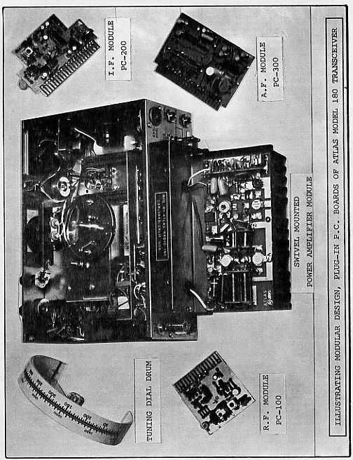
1 INTRODUCTION The Atlas 180 Transceiver is designed for single sideband and CW communications in the 20, 40, 80 and 160 meter amateur radio bands. It employs all solid-state circuitry, with modular construction. Its conservative 180 Watt power input rating will provide world-wide communications from fixed, portable or mobile installations. Atlas Radio Inc. is licensed by Southcom International, Inc. of Escondido Calif., manufacturers of military and commercial radio equipment. With this agreement Atlas Radio is able to bring the most advanced, state-of-the-art circuit designs to the amateur radio market. Les Earnshaw, founder and director of R & D at Southcom is considered to be one the foremost solid state engineers in the world, effectively proven by the rapid growth of Southcom International in the military and commercial markets of the United States as well as many other countries. The high performance and reliability of the Atlas 180 is enhanced by the finest craftsmanship, and a most thorough quality control program. Our staff is made up of highly skilled assembly workers, technicians and engineers, many of whom are radio hams. Our service department if and when needed, is dedicated to making every Atlas owner a satisfied customer. Speaking for all the gang at Atlas Radio, we wish you many hours of operating pleasure with your atlas Herb Johnson W6QKI Pres., Atlas Radio, Inc. 1
2 TABLE OF CONTENTS Technical Specifications. 2,3 Block Diagram 3 Special Circuit Features.. 4 Photos, Top-Bottom-Rear Views 6,7 Mobile Installation.. 8 AC Power Supply Console. 8 Linear Amplifier Connections 9 Operation 9,10 Antennas, Impedance Matching 11 Antennas, Mobile 12 PC-100, PC-200 Schematics PC-300, PC-500 Schematics 14 PC-400, PC-600 Schematics 15 PC-800, PC-900 Schematics 16 Voltage Chart Inside Rear Cover Chassis Schematic Insert GENERAL SPECIFICATIONS BAND COVERAGE: 20, 40, 80 and 160 meters. FREQUENCY RANGES: , , , , 14,000-14,350 kc. FREQUENCY CONTROL: highly stable VFO common to both receive and transmit modes. Tuning dial calibrated in 5 kc increments with easy interpolation to 1kc. Tuuning rate: 15 kc per revolution of the tuning knob. EXTERNAL FREQUENCY CONTROL: Rear socket provides for plug-in of external VFO or crystal oscillator accessory for separate control of transmit and receive frequencies or for networkand MARS operation. CIRCUIT DESIGN: All solid state, 4 I.C.s, 18 transistors, 32 diodes. Single conversion, 5520 kc I.F. MODES OF OPERATION: SSB: lower sideband on 40, 80, and 160 meters, upper sideband on 20 meters with SB selector switch in NORM. position. Opposite with switch in OPP. Position. CW: offset frequency in transmit mode. MODULAR CONSTRUCTION: Includes plug-in circuit boards for ease of maintenance. PLUG-IN DESIGN: Transceiver plugs into deluxe mobile bracket, or into the AC power supply console, making transfer or removal a simple operation. All connectors are standard: SO-239 antenna jack, ¼ in. phone jacks for Mic., CW key, external speaker or headphones, and linear amplifier control. POWER SUPPLY REQUIREMENTS: operates directly from 12 to 14 volt D.C. source with negative ground, (standard automotive system). Current drain is 300 to 500 ma. in receive mode, 16 amps peak in transmit mode. Atals models AR-117 and AR-230 power supply consoles are available for AC operation. FRONT CONTROLS: Tuning Dial, Dial Set, Function Switch, Band Switch, A.F. Gain, R.F. Gain, Mic. Gain, Sideband Selector, Calibrator On-Off, Dial Light Dimmer. FINISH: black vinyl covered steel cabinet, anodized aluminum panel. RECEIVER SPECIFICATIONS CIRCUIT DESIGN: Front end design provides exceptional immunity to overload and cross modulation, matching or out performing the best vacuum tube designs. Signals are converted directly to the 5520 kc I.F. without preamplification. Converter and product detector are double balanced diode rings. I.C.s are employed in the I.F. and A.F. stages. SENSITIVITY: Requires less than 0.3 microvolts for a 10 db signal-plus-noise to noise ratio. (typically 0.2 microvolts) SELECTIVITY: Crystal ladder filter, 8 poles. Bandwidths: db, db, db!! Ultimate rejection more than 120 db!! Shape factor: 1.6 IMAGE REJECTION: More than 60 db. INTERNAL SPURIOUS: Less than equivalent 1 microvolt signal. AGC CHARACTERISTICS: Audio output constant within 4 db with signal variation from 5 microvolts to more than 3 volts. OVERALL GAIN: Requires less than 1 microvolt signal for 0.5 watts audio output. (CW carrier, 1000 cycle heterodyne) AUDIO FIDELITY: 300 to 3000 cycles, plus or minus 3 db. AUDIO POWER: 2 watts to a 3 ohm speaker with less than 10% distortion. INTERNAL SPEAKER: 3 inch, 3 ohm, 0.68 oz. Magnet. Rear jack permits plug-in of external speaker, or high impedance headphones. When transceiver is plugged in to the AC power supply console, internal speaker is disconnected automatically, and front facing speaker on console becomes operative. METER: Reads S units from 1 to 9, plus 10 to 50 db. CALIBRATOR: Provides 100 kc check points for accurate dial setting. DIMENSIONS: 9 ½ in. (24.1 cm) wide, 3 ½ in. (8.9 cm) high, 9 ½ in. (24.1 cm) deep, overall. Weight: 7 ½ lbs. (3.4 kg) net. 9 lbs (4.1 kg) shipping weight. 2
3 TRANSMITTER SPECIFICATIONS CIRCUIT DESIGN: Broadband design eliminates transmitter tuning. Single conversion from I.F. to output frequency produces minimum spurious and mixing products. 2 section low-pass filters on each band provide harmonic suppression equal to commercial standards. Includes ALC and infinite SWR protection. FREQUENCY CONTROL: Internal VFO automatically transmits on exactly the same frequency that is being received. Rear socket provides for plug-in of external VFO or crystal oscillator accessory for separate control of transmit and receive frequencies, or for network and MARS operation. POWER RATING: 180 watts P.E.P. input, and CW input, (with 50 ohm resistive load and 13.6 volt D.C. supply). Power output: 80 watts minimum P.E.P. and CW (100 watts typical). EMISSION: SSB: Lower sideband on 40, 80, and 160 meters, Upper sideband on 20 meters with SB selector switch in NORM. position. Opposite with switch in OPP. Position. CW: Offset frequency. UNWANTED SIDEBAND: More than 60 db down at 1000 cycles A.F. input. THIRD ORDER DISTORTION: Approximately 30 db below peak power. SPURIOUS AND IMAGE OUTPUT: More than 40 db below peak power. HARMONIC OUTPUT: More than 35 db below peak power. CW KEYING: Manual send-receive. Semi-break-in with CW accessory installed in AC power supply console. TRANSMIT CONTROL: Press-to-talk with Mic. Button, or manual transmit with function switch on front panel. Automatic voice control when VOX accessory is installed in AC power supply console. MICROPHONE: Dynamic or crystal. Plug requirement: standard ¼ in. diam. 3 circuit phone plug. AUDIO FIDELITY: 300 to 3000 cycles, plus or minus 3 db. METER: Reads power amplifier collector current, 0-16 amperes. LINEAR AMPLIFIER CONTROL: Rear jack provides for keying of linear, and ALC control from linear. CARRIER SUPPRESSION: More than 50 db down. 3
4 SPECIAL CIRCUIT FEATURES The Atlas 180 employs several unique features in its circuit design which lead to exceptional performance. Most of the circuitry is directly descended from similar equipment manufactured for military and commercial markets by Southcom International, Inc. of Escondido California. Operating under license from Southcom, Atlas Radio has access to the very latest state-of-the-art circuit designs which have been tested, proven, and type accepted fro military and commercial use. Receiver input circuit: Referring to the block diagram, notice that there is no preamplification of the signal. After passing through input tuning circuits the signal is coupled directly into a double balanced diode ring mixer where it is heterodyned to the 5520 kc I.F. Thus, the overload and cross modulation problems commonly encountered with an RF amplifier stage are largely eliminated. This has always been somewhat of a problem with vacuum tube R.F. amplifiers, and a much more serious problem with transistor or F.E.T. amplifiers. With its advanced front end design the Atlas 180 will continue receiving signals in the presence of extremely strong adjacent channel stations that would overload, cross modulate, or desensitize other receivers. Sensitivity: As with most new developments in technology, it may be difficult to accept the fact that a proper receiver can exhibit good sensitivity without a stage, or more, of R.F. amplification prior to frequency conversion. The fact is that the Atlas 180 is at least as sensitive as the best of the tube or solid state receivers having R.F. amplifiers. This is due largely to the very low noise figure of the double balanced diode mixer, followed by a low noise I.F. amplifier. Sensitivity is rated at 0.3 microvolts for a signal-plus-noise to noise ratio of 10 db. Typical measurements will read 0.15 to 0.2 microvolts. Seelctivity: Following the low noise first I.F. amplifier, the signal passes through the crystal lattice filter, a highly sophisticated package designed specially for the Atlas 180 by Network Sciences Inc. of Phoenix Arizona. Here is where superior selectivity has been tailored to take full advantage of the extremely wide range of signal levels that the front end design is capable of handling. A 6 db bandwidth of 2700 cycles was carefully selected to provide audio response from 300 to 3000 cycles in both receive and transmit modes. While occupying slightly more bandwidth than a 2100 or 2400 cycle filter, it has been convincingly proven that the transmission and reception of the audio frequencies between 2400 and 3000 cycles provides a substantial improvement in weak signal readability. At the same time, the improved fidelity of voice communication is readily noticeable. The 6 db bandwidth of 2700 cycles is backed up by a 6 to 60 db bandwidth ratio of only 1.7 (shape factor), and ultimate rejection greater than 110 db. It is this extremely steep skirt selectivity which will reject strong adjacent channel signals. Oscillator switching: The unique method of changing from receive to transmit mode by switching the carrier oscillator and VFO is illustrated in the block diagram. This new development is responsible for great simplification of the transceiver circuit, leading to fewer components, lower cost and greater reliability. In receive mode the first mixer heterodynes the antenna signal with VFO injection. In transmit mode the first mixer functions as a balanced modulator with carrier oscillator injection and mic. amp. input. In both modes the first mixer output is at the intermediate frequency (I.F.) of 5520 kc. In receive mode the second mixer functions as a product detector with carrier oscillator injection. Its output couples audio frequencies to the receiver audio system. In transmit mode the second mixer heterodynes the I.F. signal with VFO injection. Its output is now at the transmit frequency, and is coupled through tuned circuits, preamplifiers, driver stage, and power output amplifier. Oscillator switching is accomplished with four F.E.T.s resulting in very low intercoupling between oscillators. Transmitter Broadband Circuitry: The amplifier stages of the transmitter provide full power output over the entire 1.8 to 15 mc range, and require no tuning. Tuned circuits between the second mixer and the transmitter amplifier module select the desired mixer product and reject the unwanted products. These tuned circuits are band switched and provide full coverage of each band. They are double tuned and over coupled, requiring no further adjustment after being factory set. Harmonic output from the power amplifier is suppressed by a band switched two section low pass filter. This filter is connected between the power amplifier output and the antenna terminal. The low pass filters and power amplifier are both designed for a 50 ohm load. It is important that the load be quite close to 50 ohms, non reactive, in order to operate at full rated power. Receiver Broadband Circuitry: The receiver input filters are band switched, and provide full band coverage without need for a panel peaking control. In addition, the signal passes through the low pass transmitter filter, suppressing possible interference from strong local VHF signals. 4
5 5
6 MOBILE INSTALLATION PRELIMINARY NOTES: The D.C. electrical system in an automobile may at times generate high voltage transients; spikes of voltage superimposed on the volt D.C. system. These transients may be caused by faulty brushes in the starter motor, alternator or generator, or loose wiring, and can represent a possible hazard to the semiconductors in the transceiver. For this reason we strongly urge that you read the following notes and follow them carefully: (1) Clean the battery terminals and clamps, and tighten the clamps securely. (2) Tighten battery cable terminals where they attach to the engine. (3) Inspect battery cables and terminals for corrosion or wear. Replace them if they look questionable. (4) Check battery condition frequently, especially when it approaches its warranty age limit. Use a protective silicone grease on the terminals to inhibit corrosion. (5) Check the alternator and regulator connections for tightness. Also primary ignition wiring, horn wiring, lights etc. (6) Measure the charging voltage from the alternator with the engine running at about twice idling speed. Voltage at the battery terminals should measure 13 volts minimum, 14.5 volts maximum. Consult your autoelectric service shop if correction is required. D.C. BATTERY CONNECTIONS: See Addendum Note (3) The illustrations show how the transceiver can be hung under the dash, or mounted over the transmission hump. Each installation is different, so this must be left to the individual. Consult your dealer or friends with mobile experience if need be. The brackets can be cut easily and bent as required. The smaller #6 x 3/8 in. screws are for attaching the brackets to the sides or bottom of the transceiver. They will replace the #4 x ¼ in. screws that came in the transceiver, thus allowing for the 1/8 in. thickness of the bracket. The #6 screws will make the brackets more secure than the original #4s would. The #10 screws are for securing the brackets to the underside of the dash, or to the transmission hump. NOISE SUPPRESSION The subject of suppressing automotive ignition and alternator noise is beyond the scope of this instruction manual, so it will only be mentioned briefly. Many cars will create very little interference in the HF bands covered by the Atlas 180. Almost all cars now use resistance type ignition wire, and will probably create very little ignition noise. More likely the high pitched whine from the alternator will cause more trouble. Refer to the various amateur radio handbooks, available from your dealer, for information on noise suppression. It will usually be found in the mobile chapters. Estes Engineering Co., 543 West 184 th St., Gardena, Calif., 90248, manufactures an excellent line of suppression kits which can help cure the more stubborn cases. It is quite likely that your dealer also sells the Estes Engineering line. 6
 3 in. wide rear brackets. (e) Three #10 x 1 in.")
7 DELUXE PLUG-IN MOBILE MOUNTING KIT: This kit includes: (a) 6 ½ ft D.C. power cable with 20 amp in-line fuse and transceiver plug. (b) Black anodized plug-in housing. (c) Two 9 in. and two 12 in. black anodized aluminum mounting bars. (d) 3 in. wide rear brackets. (e) Three #10 x 1 in. sheet metal screws, and two 8-32 bolts, nuts, and washers Refer to the illustrations for typical transmission hump and underdash mounting arrangements. (1) The rear bracket(s) should be angled as straight back as possible in order to give good support for pushing and pulling the transceiver in and out of the mount. (2) The mounting brackets must be cut and bent to suit the installation, each case being unique. Try different positions and select the one for best ease of operation, and least interference with automotive controls. Then carefully measure each bracket for length and angle of bend on its foot. (3) Remove the acorn nut and hex nut. Slip bracket over screw, and replace only the acorn nut. (4) Secure brackets to car with #10 sheet metal screws. Tighten screws and nuts securely. (5) Connect 52 ohm coax. cable as illustrated. (6) An external speaker may be connected as follows: Locate the speaker plug on the back of the mobile mount, just above the mic. Plug. Clip out the wire jumper going from the tip lug to the ring lug. This will disconnect the internal speaker. Connect the external speaker from the tip lug to the ground lug. INSTALLING D.C. POWER CABLE: The power cable should be run from the transceiver, through the bulkhead, and connected as close to the battery as is practical. The best way is to connect directly to the battery posts. Drill and tap into the lead terminal posts for machine screws, and secure #10 terminal lugs under these screw heads. The advantage of doing it this way is that even if the battery clamps work loose, it will not affect the transceiver connections, and the danger of intermittent transient voltage spikes will be reduced. If drilling and tapping the battery posts is not practical, then connect the cable to the engine end of the battery cables. The negative cable will usually be found going to a bolt on the engine block, while the positive cable usually goes to a bolt on the starter solenoid. Install terminal lugs at these points for connecting the power cable. The red lead goes to positive and the black to negative. A protective diode is built into the transceiver plug and will blow the in-line fuse if polarity is inadvertently connected wrong. As discussed in Preliminary notes, the battery clamps should be cleaned and tightened. All electrical connections should likewise be checked and tightened. OPTIONAL SAFETY FUSE: The D.C. power cable has a 20 amp. in-line fuse installed close to the transceiver plug. This is a convenient location, but is not always the best. A more proper location is to install a fuse close to the battery end of the power cable. There is always a possibility of short circuiting a cable to ground, either by having a bulkhead cut through the insulation, or getting pinched somewhere. With 12 gauge wire and no fuse at the battery end, the short circuit could start a fire very quickly. A second in-line fuse, fuse block, or circuit breaker may be installed near the battery if you re a worry wart. Otherwise, install the cable carefully, using tape, grommets, and plastic cable clamps where necessary. 7
8 MODEL AR-117 and AR-230 POWER SUPPLY SPECIFICATIONS ** INPUT VOLTAGE: AR-117: 117 volts AC, AR-230: 117 or 230 volts AC, (switch selected). Both models cycles. ** INPUT POWER: 10 watts average, Receive. 250 watts Transmit peak. ** OUTPUT: Low current line: 13.6 volts regulated ½ amp.high current line: 13 volts at 16 amps. ** SPEAKER: 3 x 5 in. oval, 1.1 oz. Magnet, 3 ohm voice coil. ** PLUG-IN DESIGN: Transceiver plugs directly into power supply console, automatically makes connections for antenna and front facing speaker. Mic. Jack and headphone jack are brought out to front panel. ** ACCESSORIES: Space under transceiver permits addition of VOX unit. Space in rear permits addition of semi-break-in CW/sidetone unit. ** FINISH: Textured vinyl bonded to steel, durable and scratch resistant ** DIMENSIONS: 15 ½ in. (39.4 cm) wide. 5 5/8 in. (14.3 cm) high. 9 ½ in. (24.1 cm) deep. ** WEIGHT: 17 lbs. (7.7 kg), less transceiver. 20 lbs. Shipping weight. MICROPHONE CONNECTIONS AR-117 SCHEMATIC DIAGRAM The microphone may be either a dynamic or crystal type. If a dynamic is selected, it should preferably be the high impedance type. A low impedance mic. will work, but will require higher setting of the Mic. gain control, and may require closer speaking. The choice of microphone is important for good speech quality and deserves careful consideration. Select a high quality mic. with smooth response from 300 to 3000 cycles or more. An excellent choice is the Sure 404C hand mic. PLUG CONNECTIONS: The plug required is a standard ¼ in. diam., 3 conductor type. The tip connection is the keying circuit for the press-totalk, the ring connection is for the shielded mic. lead, and the sleeve or barrel is the common ground terminal. VOX OPERATION: Most press-to-talk microphones are short circuited when the button is not pressed. For VOX operation this feature must be disabled. Refer to instructions that come with the mic. Open the case and locate the switch contacts that short the mic. circuit when the button is not pressed. Either disconnect the leads or bend the contacts so they do not make. 8
9 ATLAS 180 OPERATION CONTROLS: A.F. GAIN: Controls audio volume in receive mode. POWER SUPPLY ON/OFF, MOBILE: The function switch has an OFF position which turns off the DC power supply to the low current circuits. The high current circuits, (driver and P.A.), remain connected to the DC supply line, but arew automatically biased off when the low current line line is turned off. POWER SUPPLY ON/OFF, AC CONSOLE: The AR-117 AC console has an On/Off toggle switch which turns off the AC supply line. This switch should be used rather than the function switch OFF position. FUNCTION SWITCH: First position is OFF for mobile operation. REC position places the 180 in receive mode. Press-to-talk and VOX circuits are operative in this position. TRANS position switches the 180 into Transmit Mode in the event a mic. without a press-to-talk switch is used, or if you wish to hold in transmit mode without having to hold the button down. CW position is also transmit mode except that the mic. gain control now becomes a carrier insertion control and carrier frequency has been shifted about 500 cycles. (See CW TRANSMISSION). 9 R.F. GAIN: The purpose of the R.F. gain control is to permit decreasing of the between-speech noise level, thus providing more pleasing reception. The AGC system in the Atlas 180 has a tremendous dynamic signal range. With full R.F. Gain sensitivity will automatically return to maximum in the absence of a signal, accompanied by a natural increase in background noise. You may find it annoying to hear the noise level increase every time the person being received pauses between words or sentences. There are really only two conditions when the R.F. Gain control needs to be on full. One is when you are scanning the band and want to hear weak as well as strong signals with about the same audio volume. The other condition is when you are in a round table with both weak and strong signals. But, a lot of the time you can turn the R.F. Gain down a bit, increase the A.F. Gain correspondingly, and realize more pleasing reception.
10 BAND SELECTOR AND THE TUNING DIAL: The first position on the band switch is marked 1.8 for the kc, or 160 meter band. The upper dial scale is calibrated directly for this band. On the other bands the lower dial scale is used. It is calibrated in 5 kc increments from 0 to 350, and the dial reading is mentally added to the number on the band switch. For instance, in the 3.5 position a dial reading of 0 is 3500 kc, a reading of 100 is 3600, etc. In the 3.7 position a dial reading of 0 is 3700 kc, a reading of 100 is 3800, and a reading of 300 corresponds to 4000 kc, the upper limit of the 75 meter phone band. 80 and 75 meters are the only bands that require a little mental getting used to. The 40 and 20 meter, (or 7 and 14 mc) bands read out directly on the dial, with 0 to 300 tuning from 7000 to 7300, and 0 to 350 tuning from 14,000 to 14,350 kc. PROPER TUNING OF SINGLE SIDEBAND SIGNALS: Precise tuning of a single sideband signal is very important. Try to tune exactly to the frequency where the voice sounds normal. Avoid the habit of tuning so the voice is pitched higher than normal, and sounds like Donald Duck. This is an unfortunate habit practiced by many operators. If you tune for an unnatural high pitch, you will then be off frequency when you transmit. Chances are the other station will then shift to your frequency when you are talking, etc., and gradually you will move up or down the band. Sooner or later one of you will accuse the other of drifting.. So, take the extra care to tune for a natural sounding voice, and you will then be enjoying the very best quality in voice communications. ADJUSTMENTS TUNING KNOB TENSION: Adjustment has been provided for increasing or decreasing the torque required to turn the main tuning knob. Loosen the set screw and remove the knob. You will find a curved spring washer between two flat washers on the tuning shaft. Compressing the spring washer increases the torque. When tightening the set screw, apply inward pressure on the knob to produce the amount of tension you want. In home station use you may want no drag at all, while for mobile use you may prefer quite a bit. P.A. BIAS: this adjustment is on the back of the heat sink, and requires a small Phillips screwdriver. Idling current in TRANS mode should read ½ to 1 amp. Do not measure idling current in CW mode, as it may give a false reading. After a period of voice transmission the idling current my climb to nearly 2 amps., but will drop back when the heat sink cools. Temperature compensation of the bias supply prevents thermal runaway. CARRIER BALANCE: A trim pot. is located on the PC- 100 plug in board on the right side of the transceiver. Next to the trim pot. is a capacity trimmer which is the phase control. These trimmers should be adjusted for minimum carrier on the 1.8 mc band. Connect a dummy load to the transceiver, and measur ethe output voltage in TRANS mode with the Mic. gain at minimum. It should null down to a level of 0.1 to 0.15 volts RMS. Other bands will give a false reading due to oscillator feedthrough which is not suppressed as much as the carrier. S-METER ZERO: This is a trim pot. located on the PC-200 plug in board located under the dial drum. It can be reached with a Phillips screwdriver from the top, just behind the dial light switch. Disconnect the antenna and adjust the trim pot. for meter 0. ALC ADJUSTMENT: See Addendum Notes (1) and (2) CRYSTAL CALIBRATOR: The 100 kc calibrator should be checked every 6 months, or so, against a frequency standard such as WWV. Aging will cause it to gradually change frequency especially during the first few months. The calibrator is on the PC-800 board, mounted on the front side of the aluminum partition behind the dial drum. A capacity trimmer in the upper left hand corner is for frequency adjustment. A test lead may be run from terminal #1 of PC-100 to the antenna terminal on a general coverage receiver which is tuned to one of the WWV frequencies: 2.5, 5, 10, or 15 mc. Adjust the trimmer for zero beat when WWV interrupts their tone modulation. VOICE TRANSMISSION Normal operation is with the function switch in REC. position. Pressing the mic. button switches the transceiver into transmit mode. Or, if the VOX accessory is installed in the AC console, speaking into the mic. will switch the rig into transmit mode. A TRANS. Position is also provided on the function switch for locking in the transmit mode, or in case the mic. does not have a press-to-talk switch. MODULATION LEVEL is adjusted with the mic. gain control. When the transceiver is coupled into a proper 52 ohm load, voice peaks will be reaching about 16 amps., although the ammeter cannot respond quickly enough to respond to these peaks. Adjust the mic. gain for average readings of 5 to 7 amps. Do not run the gain above this level, or you will flat-top and distort the transmitted audio, as well as cause splatter up and down the band. ALC will help reduce this danger, but it is still possible to overmodulate, so mic. gain must be adjusted carefully. 10
11 CW TRANSMISSION The Function switch has a CW position which switches the transceiver into CW transmit mode. A jack on the back is provided for insertion of a standard ¼ in. diam. 2 conductor phone plug coming from the CW key. Keying is accomplished by bias cutoff of the I.F. amplifier. The keying circuit operates at less than 10 volts positive to ground, and draws less than 5 milliamps., so any of the electronic keyers will work OK. In CW transmit mode the carrier frequency is automatically shifted 400 to 600 cycles. This makes it possible for one transceiver to QSO another transceiver on CW without having to constantly tune the dial back and forth. On 160, 80, and 40 meters the transmit frequency is shifted lower than the receive frequency, while on 20 meters it is shifted higher. The SB selector switch must be in the NORM position for CW operation. Send-receive changeover must be made with the function switch, and it may be a bit inconvenient to pass through the TRANS. position every time. The serious CW operator will want to install the semi-break-in accessory kit in the AC console. This item installs in back of the power supply, and includes a sidetone oscillator with volume, pitch and delay controls. In CW mode the Mic. Gain control becomes a carrier insertion control. With key down, advance this control clockwise until the meter reads 12 amps. This will be 160 watts input power, (at nominal supply voltage) and output will be about 80 watts. For novice class operation, insert 6 amps. of carrier for the 75 watt legal limit. Adequate ventilation for the heat sink is particularly important in CW operation, since average power input is higher than in SSB transmission. Keep a check on heat sink temperature, and if it is running uncomfortably hot to the touch, back down on carrier insertion, or make the transmissions shorter. CAUTION---CAUTION HEAT SINK TEMPERATURE The greatest danger to the power output transistors is overheating. The black anodized heat sink is designed to cool the transistors adequately under normal operating conditions, but as with any electronic or mechanical device, it is up the operator to maintain normal conditions, and not abuse the equipment. The maximum safe temperature of the heat sink near the output transistors is about 150 deg. F. This is a temperature that will be too hot for your fingers to hold, so a good test is to put your fingers on the fins closest to the transistors. If you can hold on without a lot of discomfort, you re OK. Overheating may be caused by: (a) modulating too heavily, (b) making lengthy transmissions with short receiving periods, or (c) restriction of air circulation around the heat sink. If the air temperature is high, such as on a hot day, or in a hot parked car, cooling capacity will be reduced. A good rule is to check the heat sink from time to time, and make certain you re not running too hot. Back off on modulation level, or shorten transmission time. Under abnormal conditions, a small fan may be directed at the heat sink. This is an excellent idea if SSTV or RTTY transmission is contemplated. ANTENNA-TRANSMISSION LINE MATCHING Proper impedance match between the coaxial feedline and the antenna system is considerably more important with the broadbanded solid state amplifier than with tube type transmitters, which generally have a Pi type matching network. The SWR should be as low as it can be in order to permit full power operation. As SWR increases, power output from the Atlas 180 decreases approximately as indicated in the following chart. SWR Approx. Output watts Note: High SWR will not damage the Atlas 180. You may feel free to operate. Only power input and output will suffer. Reflected voltage will not cause damage. AMMETER READING: The ammeter on the Atlas 180 provides an excellent indicator of impedance match. In CW transmit mode the Mic. Gain control becomes the carrier insertion control. With a close match you will be able to run the ammeter up to 12 amps., or more. (with supply voltage of 13.6 VDC, or 117 VAC) If you find you can t run the amps. that high, you can be quite sure that the antenna is not matched well at that frequency. Try different parts of the band, and you can tell easily at what frequency the antenna works best. INFINITE SWR PROTECTION: The Atlas 180 has a built in reflectometer which automatically reduces transmitter drive as SWR increases. This makes the power output transistors nearly immune to damage from mismatched loads. ANTENNAS, FIXED STATION On 20 meters a doublet and most beam antennas will match quite well across the entire band. On 40 meters a doublet tuned for phone band center will match quite well across the band. On 75 meters the average doublet will have a bandwidth of about 100 kc for SWR of 1.5 or less. To work the entire band with full efficiency will require an antenna tuner. On 160 meters an antenna tuner, or at least some kind of matching system will be essential, since even at resonance it is unlikely that the feed point will be near 52 ohms. In any case, it is always best to optimize the antenna system for the frequency where you do most of your operating. ANTENNA TUNER OR MATCH BOX : An antenna tuner can be a very useful device to compensate for antenna mismatch. This may be especially true if you happen to have a favorite antenna that has been working just fine with the old tube rig, and now you discover the new solid state rig doesn t like the old antenna. Refer to the antenna handbooks for helpful data, or ask your dealer about antenna tuners now on the market. Atlas Radio will be announcing a matching antenna tuner about October 1,
12 SWR MEASUREMENTS A bridge for measuring Standing Wave Ratio is very useful, and strongly recommended for checking impedance match. Use the following procedure: (1) Switch the bridge to Forward or Sensitivity position. (2) Set the sensitivity control on the bridge to maximum clockwise position. (3) Set Mic. Gain on Atlas 180 to minimum. (4) Set the 180 function switch to CW mode. (5) Advance the Mic. Gain until meter on bridge reads just full scale. (Mic. Gain is carrier insertion control in CW mode). (6) Switch bridge to SWR or Reflected position for the SWR reading. (7) Tune the 180 up and down in frequency until you locate the minimum SWR. This will indicate the resonant frequency of the antenna, and also the SWR at that frequency. (8) Switch the 180 back to REC. mode. CAUTION: Operate the transceiver in CW mode for only short periods of time, just long enough to make the SWR measurement. Check heat sink temperature during SWR tests, and if it is getting quite warm to the touch, let the rig cool for a few minutes before continuing. CAPACITY MATCHING METHOD: This is an alternate method for matching to the mobile antenna which works quite well. A capacitor is connected from the antenna base to ground. This capacitor is part of an L network which transforms the base impedance from a low value up to 52 ohms. The small amount of L required is actually borrowed from the lower part of the loading coil. The capacity value must be determined experimentally, and will vary from band to band, as well as from installation to installation. On 75 meters the capacity will generally need to be in the 1000 to 1500 picofarad range. On 40 meters, 300 to 500 pf. On 20 meters, about 200 pf. A variable capacitor can be useful to determine what value is required. Or a collection of silver mica capacitors, some 100 pfs, 200s, 470s, and a 1000 pf can be paralleled in various combinations until the SWR comes down to a low figure. Once you know how much capacity your antenna needs, it is best to make up a permanent capacitor by paralleling two or more silver micas. This will divide the R.F. current and reduce the chances of overheating a single capacitor with too much current. Follow the procedure described under SWR Measurements when tuning the antenna. MOBILE ANTENNAS The mobile antenna generally requires more critical adjustment than the home station antenna. This is because it operates over a more narrow bandwidth, and must therefore be adjusted very accurately for resonance. Also, the base impedance is seldom very close to 52 ohms. With tube type transmitters the Pi matching network will adjust to fairly low impedances, but with a broadband solid state transmitter, such as is used in the Atlas 180, a close impedance match is necessary in order to operate at full power. Various claims about impedances are made by manufacturers of mobile antennas, but unfortunately our tests on all the most popular brands indicate that your chances of coming up with a close match are less than 1 to 10. Average base impedance is 15 to 20 ohms. Therefore, some method for transforming the base impedance to 52 ohms is required. ATLAS MODEL MT-1 TRANSFORMER: This is a broadband ferrite core transformer with a choice of 4 impedance taps. It installs inside the car body near the antenna mount. A coax feedline is run from the transceiver to the transformer and a short length is connected from the transformer to the antenna mount. There are taps for 13, 18, 23 and 52 ohms. One of these taps will provide a low SWR reading. Follow the procedure under SWR Measurements. The MT-1 transformer is available from Atlas dealers. 12

13 C101,108,109,110,112 10nF 100V disc C102 22pF 10% disc C103 50pF trimmer C104,107 2nF mylar C pF mica C pF mica C nF 50V disc C113 15uF 20V D101,2,3,4,7,8. 1N4148 D105,6. BA182 Q101 2N3866 R R pot R102 10K 0.25W R103,110 4K7 0.25W R R 0.25W R105 47R 0.25W R106,7 1K 0.25W R R 0.25W R R 0.25W L101,2 Trifilar toroid L103 IF coil L uH choke PC-100A FIRST MIXER, FIRST I.F. AMP. 13

14 PC-200A, SECOND I.F. AMP., SECOND MIXER, MIC. AMP., S-METER AMP. C201,214 15uF 20V R201,220 2k2 0.25W C202,3,5,8,9,210,213 10nF 100V disc R R 0.25W C204, nF 50V disc R203 3K9 0.25W C uF 15V R204 47R 0.25W C pF mica R205 27K 0.25W C212,216,219 1nF 20% disc R206,211 5K6 0.25W C211,220 2u2 50V R207,212, R 0.25W C215 6u8 35V R208,221 1K 0.25W C217,218 22uF 16V R209 68R 0.25W L201 IF txfmr R K 0.25W L202,203 Trifilar toroid R K 0.25W L uH choke R215,217 10K 0.25W D201,2,3,4,5 1N4148 R216 39K 0.25W Q201 MC1350P R218 3K9 0.25W Q202 CA3086 R220 1K s-meter trim 14

15 PC-300 RECEIVER AUDIO, OSCILLATOR SWITCH BOARD C301, nF 50V disc R301,4,312 5k6 0.25W C302,4,7,9,12,21,22,23,24 10nF 100V disc R302 27k 0.25W C nF 25V disc R k 0.25W C305 47uF 6V R305 1K5 0.25W C306,314,320 15uF 20V R306,11,15,19,21,22,24 1k 0.25W C308,316,319 2u2 50V R307,8,9,17 470R 0.25W C310 75uF 15V R310 10K 0.25W C313 47nF 100V R313 1M 0.25W C uF 25V R314 3K3 0.25W C nF 100V R316,18,20,23,25,26 6k8 0.25W C318 22uF 16V Q301 CA3086 D301,302 BA182 Q302 LM380N D303,4,5,6,7 1N4148 Q303,4,5,6 2N3819 L301 33uH choke 15

16 PC-400 VFO CIRCUIT BOARD AND TUNING CIRCUITS C401,2,6,7,9 10nF 100V disc R401,413 27R 0.25W C pF s-mica R402,3,9,10 10K 0.25W C pF s-mica R407 22k 0.25W C405 10pF NPO disc R R 0.25W C408 1nF disc R R 0.25W C410 22pF N150 disc R406 15k 0.25W C411 15pF NPO disc R R 0.25W C412 15pF N150 disc R411, W C413,15,18,21,24 11pF trimmer Q401,3 2N706 C414,16,19 10pF N150 disc L401 3 section osc coil C417,20 47pF NPO disc L MHz cal coil C422,25 27pF N150 disc L403 14MHz cal coil C423 68pF NPO disc L MHz cal coil C426 22pF NPO disc C427 1pF dial set C428a and b 8pF / sect main tuning 16

17 PC-500 PRE-AMPLIFIER, DRIVER, POWER AMPLIFIER C501,2,4,7,10,18,19 10nF 100V disc R515 10k bias trim pot C503,9 100nF 50V disc R R 0.25W C505 2nF 600V mylar R517 10R 2W C506,12,17 100nF 100V mylar Q501 MPS6514 C508,16 15uF 20V Q502 2N3866 C uF 50V Q503 PT5766 (TRW) C513,14 560pF 5% mica Q504,5 CTC A50-12 C pF 5% mica Later Q504,5 CT1601 R501,8,14 1k5 0.25W Q506 2N5490 R502 10R 0.25W T501 toroid transformer R503,9 470R 0.25W T502 ferrite driver txfmr R504,13 180R 0.25W T503 ferrite output txfmr R505 47R 0.25W L501 33uH choke R506 27R 0.25W L uH choke R507 2k7 0.25W L uH choke R R 0.5W L504 3 ferrite beads R511 68R 0.25W L uh choke/shunt R512 4x4R7 0.25W parallel D501,2 SI-05 17

18 C pF 5% silver mica C pF 5% silver mica C603 15pF 10% disc C604,5,6,10,11 10nF 100V disc C607 50pF trimmer (op SB) C608 50pF trimmer (norm SB) C609 10pF 10% disc C pF 5% silver mica R601 22k 0.25W R602 10k 0.25W R603,6,12 1k 0.25W R604,5 33k 0.25W R R 0.25W R608,13 100R 0.25W R609 4k7 0.25W R620,11 15k 0.25W L uH X kHz xtal (op SB) X kHz xtal (norm SB) D601 BA182 D602 1N4148 Q601,2 2N706 PC-600 CARRIER OSCILLATOR, BUFFER AMPLIFIER 18

19 C pF 10% C802 50pF trimmer C pF 5% mica C804, pF polystyrene C pF 5% mica C807, 8 680pF 5% mica C pF disc C810, 13 91pF 5% mica C811, pF trimmer C uF mylar X kc xtal R k 10% R802 1k 10% L801 5mH choke L uH coil L803, 4 1.7uH coil L uH coil L806, 7 1.4uH coil L808, 9 1.2uH coil D801 BA182 Q801 2N3819 PC-800 REC. INPUT TUNING, 100 KC CRYSTAL CALIBRATOR 19

20 C901, 4 820pF 5% poly C902, pF trimmer C pF 5% mica C906, 9 180pF 5% mica C907, pF trimmer C910,11,14,16,19 39pF 10% disc C912,13,17, pF trimmer C915, pF 10% disc R901, 2 4.7K 10% L901, 2 2.8uH toroid L903, 4 7uH toroid PC-900 TRANSMITTER INPUT TUNING 20

21 C1001, 2, pF 5% s-mica C1005, 7 820pF 5% s-mica C pF 5% s-mica C1008, pF 5% s-mica C pF 5% s-mica C pF 5% s-mica C pF 5% s-mica L1001, 2 2.9uH toroid L1003, 4 1.8uH toroid L1005, uH toroid L1007, uH toroid PC-1000/1020 LOW PASS FILTERS 21
22 ATLAS 180 ADDENDUM NOTES: (1) The ALC CONTROL has been moved to the front panel. It is now concentric with the Mic. Gain control, and is the inner ring with a black set screw indicating its position. ALC is the abbreviation for the Automatic Level Control, and refers to transmitter modulation level. It aids in preventing overmodulation which causes flat-topping of the power output stages, distortion, and splattering outside the channel. Full counterclockwise setting of the this control provides no ALC, while full clockwise setting is maximum ALC. Normally a setting around 12 o clock will be satisfactory. Some variation between bands may be noted. By having the ALC control on the front panel, you can utilize its advantages most effectively. Too little control will make it easier to over modulate, while too much control will limit output power. Try various settings and ask for signal reports until you become familiar with its effect. If you have a panoramic scanner, this is, of course, the best way to monitor your output signal. FOR CW TRANSMISSION: The ALC Control should be set to minimum, or full counterclockwise position. (2) LINEAR AMPLIFIER OPERATION: The illustration on page 9 shows how to connect a linear amplifier to the Atlas 180. ALC output from the linear may be connected to pin 4 on the AUX. plug. Special note: The ALC control voltage from the linear must be positive going. Most linears with an ALC output circuit are negative going. If this is the case with your linear, and you wish to utilize ALC control from the linear, it will be necessary that you modify the linear ALC circuit. This will usually consist of reversing one or two diodes in order to generate a positive voltage control instead of negative. In view of this requirement, you may choose to use the ALC system of the 180 alone. Most linears will operate to the full legal power limit with little or no distortion. If ALC control is coupled from the linear to the 180, then the ALC panel control on the 180 should be set to the minimum, or counterclockwise position. 22

23 (3) D.C. BATTERY CONNECTIONS: A DELUXE MOBILE MOUNT (DMK) is available from your Atlas dealer. This plug in design permits easy removal of the transceiver as all needed connections are made to the mount. All necessary hook up cables with polarity protection and hardware are part of the mount. A MOBILE BRACKET KIT (MBK) can be purchased for a permanent installation in your car or boat as well as a factory built D.C. cable (D.C.C.) with polarity protection and overload protection built in. IN THE EVENT YOU HAVE NOT PURCHASED THE DMK OR D.C.C., your transceiver comes with two banana jacks for the positive battery lead, and are to be connected in parallel. The banana plug connects to the negative battery lead. The battery leads should be of 10 or 12 gauge stranded wire of the automotive type. A 20 amp. fuse or circuit breaker should be installed in the positive lead. Caution: It is extremely important that proper polarity be observed. The positive battery lead must go to the two terminals clearly marked on the back of the transceiver. The negative battery lead must go to the transceiver chassis ground, and the banana plug is for this purpose. Even momentary connection of the wrong polarity will destroy the transistors, and void the Atlas warranty. 23
24 24
KWM-2/2A Transceiver THE COLLINS KWM-2/2A TRANSCEIVER
 KWM-2/2A Transceiver Click the photo to see a larger photo Click "Back" button on browser to return Courtesy of Norm - WA3KEY THE COLLINS KWM-2/2A TRANSCEIVER Unmatched for versatility, dependability and
SUBELEMENT T4. Amateur radio practices and station set up. 2 Exam Questions - 2 Groups
 SUBELEMENT T4 Amateur radio practices and station set up 2 Exam Questions - 2 Groups 1 T4A Station setup: connecting microphones; reducing unwanted emissions; power source; connecting a computer; RF grounding;
CON NEX HP. OWNER'S MANUAL Full Channel AM/FM Amateur Mobile Transceiver TABLE OF CONTENTS TUNING THE ANTENNA FOR OPTIMUM S.W.R..
 TABLE OF CONTENTS PAGE SPECIFICATIONS... 2 INSTALLATION... 3 LOCATION... 3 CON NEX - 4300HP MOUNTING THE RADIO... 3 IGNITION NOISE INTERFERENCE... 4 ANTENNA... 4 TUNING THE ANTENNA FOR OPTIMUM S.W.R..
hallicrafters PERFORMANCE SPECIFICATIONS MODEL: SR-2000 LATEST REVISION: 18 JAN 66 Code ident # Specification #
 hallicrafters PERFORMANCE SPECIFICATIONS MODEL: SR-2000 LATEST REVISION: 18 JAN 66 Code ident # 26916 Specification # 093-002154 I. GENERAL A. Power input 117V 50-60 cycles from a source capable of delivering
Technician Licensing Class. Lesson 4. presented by the Arlington Radio Public Service Club Arlington County, Virginia
 Technician Licensing Class Lesson 4 presented by the Arlington Radio Public Service Club Arlington County, Virginia 1 Quiz Sub elements T6 & T7 2 Good Engineering Practice Sub element T8 3 A Basic Station
MODEL FS-4 INSTRUCTION MANUAL R.L. DRAKE COMPANY, MIAMISBURG, OHIO, U.S.A.
 MODEL FS-4 F R E Q U E N C Y S Y N T H E S I Z E R INSTRUCTION MANUAL R.L. DRAKE COMPANY, MIAMISBURG, OHIO, U.S.A. LIMITED WARRANTY R. L. DRAKE COMPANY warrants to the original purchaser that this product
Frequency range: BAND RANGE MHz MHz
 INSTRUCTION SHEET NO. 20 POWER-MITE PM3 and PM3A DESCRIPTION The Power-Mite 3 and 3A are self-contained CW transceivers covering 40 and 20 meters. The receiver is compromised of a variable oscillator operating
MFJ-752C SIGNAL ENHANCER II
 MFJ-752C SIGNAL ENHANCER II INTRODUCTION The improved MFJ-752C SIGNAL ENHANCER II is comprised of two tunable audio filtering systems designed to clarity and remove interfering signals from both voice
Elmer Session Hand Out for 3/3/11 de W6WTI. Some Common Controls Found On Amateur Radio Transceivers. (From ARRL web site tutorial)
") Elmer Session Hand Out for 3/3/11 de W6WTI Some Common Controls Found On Amateur Radio Transceivers. (From ARRL web site tutorial) The placement of the controls may vary from manufacturer to manufacturer
Elmer Session Hand Out for 3/3/11 de W6WTI Some Common Controls Found On Amateur Radio Transceivers. (From ARRL web site tutorial) The placement of the controls may vary from manufacturer to manufacturer
DX 33HML. Full Channel AM/FM Mobile Transceiver OWNER S MANUAL. Printed In Malaysia AT H PD000802
 DX 33HML Full Channel AM/FM Mobile Transceiver Printed In Malaysia AT3601014H PD000802 OWNER S MANUAL TABLE OF CONTENTS Page Specification.................................... 2 Installation Location.....................................
MFJ SIGNAL ENHANCER II
 MFJ SIGNAL ENHANCER II Model MFJ-752D INSTRUCTION MANUAL CAUTION: Read All Instruction Before Operating Equipment MFJ ENTERPRISES, INC. P.O. BOX 494, MISSISSIPPI STATE, MS 39762, USA 925-0037D-752D-REV
Amateur Radio Examination EXAMINATION PAPER No. 275 MARKER S COPY
 01-6-(d) An Amateur Station is quoted in the regulations as a station: a for training new radio operators b using amateur equipment for commercial purposes c for public emergency purposes d in the Amateur
DX 73V OWNER S MANUAL FULL FEATURED AM/FM MOBILE TRANSCEIVER. WARRANTY This radio is covered by a two year limited parts and labor warranty.
 WARRANTY This radio is covered by a two year limited parts and labor warranty. Limited means that we will repair problems caused by factory defects or normal use at no charge. Before returning a radio
Assembly Instructions for the FRB FET FM 70 Watt Amp
 Assembly Instructions for the FRB FET FM 70 Watt Amp 1.) Orient the circuit board with the diagram 2.) Use a narrow chisel tip 25-30 watt soldering iron for assembly 3.) All the small parts are taped onto
DX 29HP. 10 Meter Amateur Mobile Transceiver OWNER S MANUAL PRINTED IN MALAYSIA PN:A412308CNA
 DX 29HP 10 Meter Amateur Mobile Transceiver OWNER S MANUAL PRINTED IN MALAYSIA PN:A412308CNA TABLE OF CONTENTS Page Specification.................................... 2 Installation Location.....................................
Introduction LOADING COIL COUNTERPOISE ATTACHMENT ANTENNA ATTACHMENT. Figure 1: MFJ-1625 Window/Balcony Mount Antenna
 Introduction MFJ-1625 The MFJ-1625 is a 200 Watt antenna tuner that was designed to provide portable or permanent HF communications on 80 through 10 meters and VHF on 6 meters. The universal mount design
The ROSE 80 CW Transceiver (Part 1 of 3)
") Build a 5 watt, 80 meter QRP CW Transceiver!!! Page 1 of 10 The ROSE 80 CW Transceiver (Part 1 of 3) Build a 5 watt, 80 meter QRP CW Transceiver!!! (Designed by N1HFX) A great deal of interest has been
Build a 5 watt, 80 meter QRP CW Transceiver!!! Page 1 of 10 The ROSE 80 CW Transceiver (Part 1 of 3) Build a 5 watt, 80 meter QRP CW Transceiver!!! (Designed by N1HFX) A great deal of interest has been
Definitions of Technical Terms
 Definitions of Technical Terms Terms Ammeter Amperes, Amps Band Capacitor Carrier Squelch Diode Dipole Definitions How is an ammeter usually connected = In series with the circuit What instrument is used
DX 33HP. 10 Meter Amateur Mobile Transceiver OWNER S MANUAL. Download this Manual Free of Charge at
 DX 33HP SIG 1 3 TX PWR 5 7 9+30dB POWER HI NB/ANL MED LO HI LO BAND ECHO RX/TX VOL SQ MIC RF FM PA AM D/A E/B F/C ECHO TIME BAND 10 Meter Amateur Mobile Transceiver Download this Manual Free of Charge
 file:///c /BoatAnchors/Hammarlund/HQ170A/HQ170SVC.TXT Dear OM: This form is being prepared to provide prompt attention to a complaint as a result of trouble that may be experienced in the field. In addition
MFJ-969 Versa Tuner II Instruction Manual
 MFJ-969 Versa Tuner II Instruction Manual General Information The MFJ-969 is a 300 watt RF output power antenna tuner that will match any transmitter or transceiver to virtually any antenna. Peak or average
Mirage B-320-G FEATURES
 Mirage B-320-G The Mirage B-320-G is a VHF power amplifier designed for 2 meters covering 144-148 MHz. The Hi and Lo input selector switch makes this amp useable for both handheld and mobile transceivers.
Vectronics VC-300D DIGITAL BARGRAPH ANTENNA TUNER
 Vectronics VC-300D DIGITAL BARGRAPH ANTENNA TUNER FEATURES The Vectronics VC-300D Antenna Tuner optimizes the performance of your antenna and transmitter, receiver, or transceiver by providing adjustable
Radio Station Setup and Electrical Principles
 Radio Station Setup and Electrical Principles Covers sections: T4A-T5D Seth Price, N3MRA February 20, 2016 Outline 4.1 Station Setup 4.2 Operating Controls 4.3 Electronic Principles 4.4 Ohm s Law 4.5 Power
Some KWM-2/2A Tricks. January By Georges, F6CER CCAE# 098. Some KWM-2/2A Tricks -
 Some KWM-2/2A Tricks January 2016 By Georges, F6CER CCAE# 098 Some KWM-2/2A Tricks Most of the KWM-2 transceivers that can be found in Europe belong to the first generation manufactured at the beginning
The 21st Century R-390A/URR Reference Y2K-R3 Edited 7/09: No Technical Changes Chapter 2 - Operation. Page Table Of Contents 2-1
 Edited 7/09: No Technical Changes Chapter 2 - Operation Page Table Of Contents 2-1 2.1 Introduction. 2-2 2.2 Controls and Indicators 2-2 2.3 Operating Instructions And Control Settings 2-9 2.3.1 Pre-operational
Central Electronics Model 600L Linear Amplifier
 INTRODUCTION This manual has been reproduced by James Lawrence, NA5RC, a 600L owner. Text no longer applicable such as insurance claim with the carrier has been deleted. Some capitalization and grammar
DX AM FM SSB CW PA Amateur Base Station Transceiver OWNER S MANUAL RX / TX 2 4 POWER NF CHANNEL MODE RF POWER OFF CAL OFF OFF CALIBRATE
 1 2 3 6 4050 ULA 6070 TI 80 90 100 9 DX 2517 2517 RX / TX 0 2 4 SWR WATTS SET 81012 22 1 010 3 2030 5 MOD 7 ON dbover 9 SIGNAL +20 +40+60 PA FM AM USB LSB CW POWER ON SWR NB / ANL R.BEEP +10KHz NF CHANNEL
GRAND STRAND AMATEUR RADIO CLUB
 The GRAND STRAND AMATEUR RADIO CLUB (GSARC) Myrtle Beach SC is offering used amateur related equipment for sale. Written bids may be submitted to the GSARC up to Friday, November 23 rd, 2018. Only currently
DELUXE 18CHANNEL SSB/AM CB TRANSCEIVER OWNER'S GUIDE
 DELUXE 18CHANNEL SSB/AM CB TRANSCEIVER OWNER'S GUIDE General Description The Bush Ranger is a combination transmitter and receiver designed for use in the Australian 27 MHz Citizens radio service. It is
MFJ-219/219N 440 MHz UHF SWR Analyzer TABLE OF CONTENTS
 MFJ-219/219N 440 MHz UHF SWR Analyzer TABLE OF CONTENTS Introduction...2 Powering The MFJ-219/219N...3 Battery Installation...3 Operation Of The MFJ-219/219N...4 SWR and the MFJ-219/219N...4 Measuring
D ELCO. electronic parts AUTO RADIO BULLETIN. Connect Signal Generator to
 D ELCO electronic parts AUTO RADIO BULLETIN Bulletin 6D-864 Date 10-15-56 Page 1 FIRST ISSUE SUBJECT: SERVICE INSTRUCTIONS - CHEVROLET CUSTOM DELUXE WITH PUSH BUTTON TUNING - MODEL 987575 GENERAL M O U
Installation... 3 Installing The Radio... 3 Ignition Noise Interference... 4 Antenna... 4 External Speaker... 4 Public Address...
 TABLE OF CONTENTS CHAPTER 1 Specifications.............................................. 2 PAGE BIG RIG SERIES S 1 MOD PW R 20 0 3 SW R 40 1 5 5 60 1.5 7 10 2 9 20 80 3 30 +20 40 50 +40 100% MAX db +60
HF Amateur SSB Receiver
 HF Amateur SSB Receiver PCB Set for radio club project http://rhelectronics.net PCB for DIY HF Amateur SSB Receiver 20M The receiver is a simple syperheterodyne type with quartz crystal filter. The circuit
HAMTRONICS TB901 FM EXCITER INSTALLATION, OPERATION, & MAINTENANCE
 HAMTRONICS TB901 FM EXCITER INSTALLATION, OPERATION, & MAINTENANCE GENERAL INFORMATION. The TB901 is a single-channel low power fm transmitter (exciter) designed to provide 300-600 milliwatts continuous
19'' Rack Mount 300 Watt Power Amplifier/ Mixer w/70v Output & Mic Talkover USER MANUAL
 19'' Rack Mount 300 Watt Power Amplifier/ Mixer w/70v Output & Mic Talkover USER MANUAL Your new PYRAMID PA305 300 Watt P.A. Amplifier gives you the power and versatility you need in a professional sound
The G4EGQ RAE COURSE Lesson 9 Transmitters Lesson 8 looked at a simple transmitter exciter comprising of oscillator, buffer and multiplier stages.
 Lesson 8 looked at a simple transmitter exciter comprising of oscillator, buffer and multiplier stages. The power amplifier The output from the exciter is usually very low and it is necessary to amplify
N3ZI Kits General Coverage Receiver, Assembly & Operations Manual (For Jun 2011 PCB ) Version 3.33, Jan 2012
 Version 3.33, Jan 2012") N3ZI Kits General Coverage Receiver, Assembly & Operations Manual (For Jun 2011 PCB ) Version 3.33, Jan 2012 Thank you for purchasing my general coverage receiver kit. You can use the photo above as a
N3ZI Kits General Coverage Receiver, Assembly & Operations Manual (For Jun 2011 PCB ) Version 3.33, Jan 2012 Thank you for purchasing my general coverage receiver kit. You can use the photo above as a
VC-300D VECTRONICS R. Digital Bar Graph Antenna Tuner. Owner's Manual. CAUTION: Read All Instructions Before Operating Equipment!
 VC-300D Digital Bar Graph Antenna Tuner CAUTION: Read All Instructions Before Operating Equipment! VECTRONICS R... the finest amateur radio products made 300 Industrial Park Road Starkville, MS 39759 (662)
Users Manual. 200W HF/50MHz Band Auto Antenna Tuner. Model HC-200AT
 Users Manual 200W HF/50MHz Band Auto Antenna Tuner Model HC-200AT Caution 1. Never remove or open the tuner cover while transmitting. When there is RF in the circuits of the tuner, there will be high voltage
Assembly Instructions for the 1.5 Watt Amplifier Kit
 Assembly Instructions for the 1.5 Watt Amplifier Kit 1.) All of the small parts are attached to a sheet of paper indicating both their value and id. 2.) Leave the parts affixed to the paper until you are
Hendricks QRP Kits BITX20A to BITX17A Conversion Instructions
 Hendricks QRP Kits BITX20A to BITX17A Conversion Instructions 30 November 2008 Converting your BITX20A Kit to a BITX17A Kit is not all that complex. It only requires that you change crystals and some resonance
WA3RNC 30 METER CRYSTALPLEXER TRANSMITTER KIT ASSEMBLY INSTRUCTIONS
 WA3RNC 30 METER CRYSTALPLEXER TRANSMITTER KIT ASSEMBLY INSTRUCTIONS Description The WA3RNC 30 Meter Crystalplexer is a low power crystal controlled QRP transmitter offering a significantly improved tuning
DX 66V OWNER S MANUAL. Full Channel AM/FM Mobile Transceiver Built in Frequency Counter with Roger Beep
 WARRANTY This radio is covered by a two year limited parts and labor warranty. Limited means that we will repair problems caused by factory defects or normal use at no charge. Before returning a radio
Operation Manual. SlJPER ST AR Channel Mobile 5-Mode Transceiver -----~- --:.. KTSS200NXX ,, I
 Operation Manual!.,, SlJPER ST AR 2000 200 Channel Mobile 5-Mode Transceiver -----~- --:.. KTSS200NXX General Description l Frequency/Channel Chart The Super Star -2000 is a combination transmitter-receiver
INSTRUCTIONS FOR INSTALLATION AND OPERATION OF THE MEISSNER SIGNAL SHIFTER MODEL EX
 INSTRUCTIONS FOR INSTALLATION AND OPERATION OF THE MEISSNER SIGNAL SHIFTER MODEL EX I. INTRODUCTION A. The MEISSNER SIGNAL SHIFTER is a variable frequency exciter, with output over the entire ranges of
Lesson 9: Base Stations
 Lesson 9: Base Stations Preparation for Amateur Radio Technician Class Exam Topics Home Stations Basic Station Layout RTTY and Data Communications Station Accessories Wavelengths Feed Lines Impedance-matching
Hallicrafters SX-88 Owners Manual
 Hallicrafters SX-88 Owners Manual Images and text excerpted from original Hallicrafters literature. Section 1. General Description The Hallicrafters SX-88 represents the ultimate in precision communications
DEM Part Number L144-28INTCK 144 MHz Transverter Kit and complete kit
 DEM Part Number L144-28INTCK 144 MHz Transverter Kit and complete kit Power Out: Noise Figure and Gain: DC Power Requirement: 50 mw linear minimum 3.5 db NF nominal, 5 dbg maximum 12-15.5 VDC, 13.8 nominal
RITEK RIT for Collins KWM-2/2A 10/01/2002
 RITEK RIT for Collins KWM-2/2A 10/01/2002 The RITEK RIT (receiver incremental tuning) control was developed for KWM-2/2A in 1992 to "clarify" received signals differing from the transmit frequency indicated
A 75-Watt Transmitter for 3 Bands Simplified Shielding and Filtering for TVI BY DONALD H. MIX, W1TS ARRL Handbook 1953 and QST, October 1951
 A 75-Watt Transmitter for 3 Bands Simplified Shielding and Filtering for TVI BY DONALD H. MIX, W1TS ARRL Handbook 1953 and QST, October 1951 The transmitter shown in the photographs is a 3-stage 75-watt
The Walford Electronics Ford Receiver Kit Project Construction Manual
 The Walford Electronics Ford Receiver Kit Project Construction Manual Walford Electronics Ford Receiver construction manual V1.5 Page 1 of 22 Introduction The Ford receiver has four stages: The first stage
KACHINA 1 SSB TRANSCEIVER
 KACHINA 1 SSB TRANSCEIVER THEORY OF OPERATION The Kachina 1 Amateur Band Transceiver is a highly sophisticated, state of the art, piece of communication equipment, housed in the smallest of packages. Yet,
ALWAYS ATTACH THE SAFETY ROPE TO A STABLE SUPPORT BEFORE ATTEMPTING TO ATTACH THE UNIVERSAL MOUNT TO A WINDOW FRAME OR RAIL.
 MFJ-1623 Introduction The MFJ-1623 was designed to provide portable or permanent HF communications on 30 through 10 meters and VHF on 6 meters. The universal mount design allows the user to install the
Instruction Kit MIXER AMPLIFIER GT 60C GT 125C. GROMMES-PRECISION SINCE-46
 Instruction Kit GT 60C GT 125C MIXER AMPLIFIER GROMMES-PRECISION 1-800-SINCE-46 www.grommesprecision.com Thank you for purchasing from Grommes~Precision! Grommes~Precision and its commercial audio division,
RCI-6300F25/150. Owner's Manual. AM/FM Amateur Transceiver With Built-in Frequency Counter. Table of Contents. Downloaded from
 Table of Contents RCI-6300F25/150 AM/FM Amateur Transceiver With Built-in Frequency Counter PAGE Chapter 1 Specifications...... 2 Chapter 2 Installation...... 3 Installing the Radio... 3 Ignition Noise
F O R T H E L O V E O F M U S I C LP100 OWNER'S MANUAL AND INSTALLATION GUIDE INTRODUCTION
 F O R T H E L O V E O F M U S I C LP100 OWNER'S MANUAL AND INSTALLATION GUIDE INTRODUCTION You have purchased an amplifier that leads the way with sound quality, reliability, and features. These high performance
RadiØKit Μ CW HAM RADIO TRANSCEIVER KIT. Assembly and operating manual
 RadiØKit-120 20Μ CW HAM RADIO TRANSCEIVER KIT Assembly and operating manual Boreiou Ipirou 78 Kolonos Athens- Greece - 10444 Tel: 210.5150527 210.5132673 www.freebytes.com Thank you for buying RadiØKit-1,
EDACS WALL MOUNT STATION. Maintenance Manual. Mobile Communications LBI-31838A TABLE OF CONTENTS
 A Mobile Communications EDACS WALL MOUNT STATION TABLE OF CONTENTS SYSTEM BOARD & REGULATOR BOARD.......... LBI-31892 KEY/DISPLAY BOARD MAINTENANCE MANUAL.... LBI-31940 Maintenance Manual Printed in U.S.A.
Manual AMERITRON QSK-5PC T/R SWITCH PC BOARD INTRODUCTION
 Manual Instruction AMERITRON QSK-5PC T/R SWITCH PC BOARD INTRODUCTION The Ameritron QSK-5PC is a PIN diode QSK circuit board designed for use in Ameritron's AL-80A, AL-80B, AL-82, AL-1500 and AL- 1200
UNITED MOTORS SERVICE D IV ISIO N OF GENERAL M O TO RS C O R P O R A T IO N. General Offices - Detroit AUTO RADIO BULLETIN
 UNITED MOTORS SERVICE D IV ISIO N OF GENERAL M O TO RS C O R P O R A T IO N General Offices - Detroit AUTO RADIO BULLETIN Bulletin 6D-855 Date 11-1-54 Page 1 FIRST ISSUE SUBJECT: SERVICE INSTRUCTIONS -
The amazing evolution of the 706 series
 The amazing evolution of the 706 series The IC-706MKIIG carries on the 706 series tradition of base station performance and features in a mobile reg-sized package. Building on this legacy, frequency coverage
1997 MFJ ENTERPRISES, INC.
 INSTRUCTION MANUAL CAUTION: Read All Instructions Before Operating Equipment MFJ ENTERPRISES, INC. 300 Industrial Park Road Starkville, MS 39759 USA Tel: 601-323-5869 Fax: 601-323-6551 VERSION 6C COPYRIGHT
Construction Manual 4m-Linear-Transverter XV4-15
 Construction Manual 4m-Linear-Transverter XV4-15 Holger Eckardt DF2FQ Kirchstockacherstr. 33 D-85662 Hohenbrunn 3207 Technical data exciter frequency: 21.0... 21.5 MHz RF frequency: 70.0.. 70.5 MHz supply
Building the Sawdust Regenerative Receiver
 Building the Sawdust Regenerative Receiver Introduction The Sawdust is a super regenerative receiver using the basic Armstrong design architecture. The receiver uses one toroidal transformer to provide
VECTRONICS HFT-1500 Digital Bargraph Antenna Tuner
 Table of Contents FEATURES... 1 SPECIFICATIONS... 1 FRONT PANEL INDICATORS AND CONTROLS... 1 CONTROLS... 1 REAR PANEL CONNECTORS... 1 OTHER... 2 CONTOLS / CONNECTORS... 2 FRONT PANEL FUNCTIONS... 2 REAR
MFJ-249B HF/VHF SWR ANALYZER
 TABLE OF CONTENTS MFJ-249B... 2 Introduction... 2 Powering The MFJ-249B... 3 Battery Installation... 3 Alkaline Batteries... 3 NiCd Batteries... 4 Power Saving Mode... 4 Operation Of The MFJ-249B...5 SWR
MZ2 HEADPHONE AMPLIFIER, PREAMP, & STEREO AMPLIFIER USER GUIDE
 MZ2 HEADPHONE AMPLIFIER, PREAMP, & STEREO AMPLIFIER USER GUIDE Linear Tube Audio Takoma Park, MD, USA WARNING: For safety, the cover of this amplifier should be secured at all times. DC voltages as high
Technician License Course Chapter 3 Types of Radios and Radio Circuits. Module 7
 Technician License Course Chapter 3 Types of Radios and Radio Circuits Module 7 Radio Block Diagrams Radio Circuits can be shown as functional blocks connected together. Knowing the description of common
18-CHANNEL MOBILE CB TRANSCEIVER MODEL CB-845
 18-CHANNEL MOBILE CB TRANSCEIVER MODEL CB-845 INSTRUCTION HANDBOOK RAll JEFFERSOn CITIZEN BAND RADIO MESSAGE TO THE OWNER CONGRATULATIONS! As the new owner of Ray Jefferson Model CB-845 CB Mobile Transceiver,
KN-Q10 Assembly Manual
 KN-Q10 Assembly Manual Translated by Adam Rong, BD6CR/4 with permission from Ke Shi, BA6BF Edited by Stephen, VK2RH Revision B, Oct 14, 2010 Thank you for purchasing the KN-Q10 4 Band SSB/CW Dual Mode
MFJ-949E. tuner antenowy skrzynka antenowa. Instrukcja obsługi. importer:
 Instrukcja obsługi MFJ-949E tuner antenowy skrzynka antenowa importer: PRO-FIT Centrum Radiokomunikacji InRadio ul. Puszkina 80 92-516 Łódź tel: 42 649 28 28 e-mail: biuro@inradio.pl www.inradio.pl MFJ-949E
LBI-4938C. Mobile Communications MASTR II POWER AMPLIFIER MODELS 4EF4A1,2,3. Printed in U.S.A. Maintenance Manual
 C Mobile Communications MASTR II POWER AMPLIFIER MODELS 4EF4A1,2,3 Printed in U.S.A. Maintenance Manual TABLE OF CONTENTS DESCRIPTION.................................................... 1 CIRCUIT ANALYSIS.................................................
How The Transmitter Works
 Mike Bray, K8DDB Refer to the schematic of the transmitter on page 7 of the manual. The crystal-controlled oscillator, V generates a small amount of r.f. power which is used to drive the amplifier, V2.
2006 MFJ ENTERPRISES, INC.
 Model MFJ-207 INSTRUCTION MANUAL CAUTION: Read All Instructions Before Operating Equipment MFJ ENTERPRISES, INC. 300 Industrial Park Road Starkville, MS 39759 USA Tel: 662-323-5869 Fax: 662-323-6551 VERSION
HF Receivers, Part 2
 HF Receivers, Part 2 Superhet building blocks: AM, SSB/CW, FM receivers Adam Farson VA7OJ View an excellent tutorial on receivers NSARC HF Operators HF Receivers 2 1 The RF Amplifier (Preamp)! Typical
Beta-test ED1 PCB installed in I0CG s K1
 K1 SSB Modification (Ed.2) This description provides the receiver (RX) modifications, assembly, alignment and operation as a first step. In a second step you can add the remaining transmitter (TX) modifications,
REPAIRING THE RM KL400 LINEAR AMPLIFIER.
 REPAIRING THE RM KL400 LINEAR AMPLIFIER. Les Carpenter G4CNH December 2012 Page 1 of 20 The following is a step by step guide to fixing your KL400 amplifier. Each part will be individually tested up to
Introduction. Understanding Power Ratings. Peak Reading SWR/Wattmeter
 Introduction The MFJ-962D is a "T" network roller inductor tuner with built-in antenna switching, RF power and SWR metering and a 1:1 balun. The largest amplifiers that can safely be used include the Heathkit
Model 7000 Low Noise Differential Preamplifier
 Model 7000 Low Noise Differential Preamplifier Operating Manual Service and Warranty Krohn-Hite Instruments are designed and manufactured in accordance with sound engineering practices and should give
A GOOD REGENERATIVE RECEIVER WITH SIMPLE FINE TUNING (2008)
") A GOOD REGENERATIVE RECEIVER WITH SIMPLE FINE TUNING (2008) A good SSB-CW-AM regenerative receiver with a fine tuning by moving the wooden stick with a grounded piece of PCB towards the coil. A good regenerative
A GOOD REGENERATIVE RECEIVER WITH SIMPLE FINE TUNING (2008) A good SSB-CW-AM regenerative receiver with a fine tuning by moving the wooden stick with a grounded piece of PCB towards the coil. A good regenerative
OWNER'S MANUAL Channels All-Mode AM/FM/USB/LSB Built in Frequency Counter Mobile Transceiver with Roger Beep
 SUPER STAR 7QOODX OWNER'S MANUAL 3360 Channels All-Mode AM/FM/USB/LSB Built in Frequency Counter Mobile Transceiver with Roger Beep TABLE OF CONTENTS Page Specifications... 2 Installation Location... 4
Construction Manual 6m-Linear-Transverter XV6/10
 Construction Manual 6m-Linear-Transverter XV6/10 Holger Eckardt DF2FQ Kirchstockacherstr. 33 D-85662 Hohenbrunn 2606 Technical data exciter frequency: 28... 30 MHz RF frequency: 50... 52 MHz supply voltage:
Building the Sawdust Regenerative Receiver
 Building the Sawdust Regenerative Receiver Introduction The Sawdust is a super regenerative receiver using the basic Armstrong design architecture. The receiver uses one toroidal transformer to provide
Radio Receivers. Al Penney VO1NO
 Radio Receivers Al Penney VO1NO Role of the Receiver The Antenna must capture the radio wave. The desired frequency must be selected from all the EM waves captured by the antenna. The selected signal is
TOA PROFESSIONAL POWER AMP
 Operating Instruction Manual TOA PROFESSIONAL POWER AMP Model P-150M, P-300M TOA ELECTRIC CO, LTD. KOBE, JAPAN Contents Precautions... 2 General Description... 2 Features... 3 Specifications... 4~5 Performance
MFJ-203 Bandswitched Dip Meter
 MFJ-203 Bandswitched Dip Meter Thank you for purchasing the MFJ-203 Bandswitched Dip Meter. The MFJ-203 Bandswitched Dip Meter is a solid state bandswitched adaptation of the traditional grid dip meter.
UNITED MOTORS SERVICE AUTO RADIO BULLETIN
 UNITED MOTORS SERVICE DIVISION OF GENERAL MOTORS CORPORATION General Offices - Detroit AUTO RADIO BULLETIN Bulletin 6D-854 Date 11-1-54 Page 1 FIRST ISSUE GENERAL SUBJECT: SERVICE INSTRUCTIONS - 12V CHEVROLET
User Guide for the Alpha Loop Sr Antenna
 User Guide for the Alpha Loop Sr Antenna Manufactured by: Alpha Antenna 1.888.482.3249 Website: http://alphaantenna.com Available from: Amateur Radio Store Website: https://amateurradiostore.com User Guide
INSTRUCTION MANUAL. Specifications Electrical. Front-To-Back Ratio VSWR at Resonance Less than 1.5:1 Nominal Impedance. Mechanical
 300 Industrial Park Road, Starkville, MS 39759 Ph: (662) 323-8538 FAX: (662) 323-6551 TH-3JRS Tri-band HF 3 Elements Beam Covers 10, 15 and 20 Meters INSTRUCTION MANUAL WARNING Installation of this product
TZ-RD-1740 Rotary Dipole Instruction Manual
 TZ-RD-1740 17/40m Rotary Dipole Instruction Manual The TZ-RD-1740 is a loaded dipole antenna for the 40m band and a full size rotary dipole for the 17m band. The antenna uses an aluminium radiating section
LeMay Audio Products. MK-I Preamplifier Users Manual John P. LeMay All Rights Reserved Rev A
 LeMay Audio Products MK-I Preamplifier Users Manual 2008 John P. LeMay All Rights Reserved Rev A 08.12.24 Congratulations on purchasing one of the world s finest professional instrument preamplifiers!
TS-590SG HF/ 50MHz All-Mode TRANSCEIVER_
 New Product Release Information Oct 2014 TS-590SG HF/ 50MHz All-Mode TRANSCEIVER_ Kenwood introduces Updated to new G version new HF/50MHz All-Mode Transceiver Four years ago we launched our best-selling
Model Operating Manual
 Model 7500 DC to 1MHz Wideband Power Amplifier Operating Manual Copyright 2004. All rights reserved. Contents of this publication may not be reproduced in any form without the written permission of Krohn-Hite
PA FAN PLATE ASSEMBLY 188D6127G1 SYMBOL PART NO. DESCRIPTION. 4 SBS /10 Spring nut. 5 19A702339P510 Screw, thread forming, flat head.
 MAINTENANCE MANUAL 851-870 MHz, 110 WATT POWER AMPLIFIER 19D902797G5 TABLE OF CONTENTS Page DESCRIPTION.............................................. Front Page SPECIFICATIONS.................................................
ELECRAFT KX3 EXTENDED VFO TEMPERATURE COMPENSATION PROCEDURE Copyright 2012 Elecraft LLC Rev. A9, November 14, 2012
 ELECRAFT KX3 EXTENDED VFO TEMPERATURE COMPENSATION PROCEDURE Copyright 2012 Elecraft LLC Rev. A9, November 14, 2012 Introduction The KX3 standard VFO temperature compensation is entirely adequate for most
Model Quality in Test and Measurement Since 1949 OUTSTANDING PERFORMANCE DESCRIPTION APPLICATIONS ADDITIONAL FEATURES
 Quality in Test and Measurement Since 1949 DC Source/Calibrators, Tunable Electronic Filters, Wideband Power Amplifiers Precision Phasemeters, Distortion Analyzers Function Generators, RC Oscillators Model
12kHz LIF Converter V2.43 9Mhz version
 12kHz LIF Converter V2.43 9Mhz version Please Note: This document supersedes all previously released documents and drawings on the LIF subject. This is the latest and most up-to-date document at this time.
Chapter 3. Electricity, Components and Circuits. Metric Units
 Chapter 3 Electricity, Components and Circuits Metric Units 1 T5B02 -- What is another way to specify a radio signal frequency of 1,500,000 hertz? A. 1500 khz B. 1500 MHz C. 15 GHz D. 150 khz T5B07 --
HAMTRONICS R144 VHF FM RECEIVER, REV. 4/94: INSTALLATION AND MAINTENANCE
 HAMTRONICS R144 VHF FM RECEIVER, REV. 4/94: INSTALLATION AND MAINTENANCE FUNCTIONAL DESCRIPTION. The R144 is a premium commercial grade single-channel vhf fm receiver. It features a helical resonator front