4700 APCO25 CONVENTIONAL HANDHELD RADIO OPERATING MANUAL
|
|
|
- Lora Lucas
- 5 years ago
- Views:
Transcription
1 4700 APCO25 CONVENTIONAL HANDHELD RADIO
2 ASELSAN Inc. 3 November 2006 The continuous improvement of its products is the intent of ASELSAN, who reserves the right to make design changes without notice. All rights reserved. reproduction of issue to third parties in any form whatever is not permitted without written permission from the proprietors. PO. Box 101 Yenimahalle, Ankara TURKEY Tel: * Fax: lojistik_destek@aselsan.com.tr
3 DEVICE SHOULD BE OPENED BY AUTHORIZED PERSONEL. OTHERWISE IT WILL BE OUT OF WARRANTY. BEFORE GETTING START TO USE THE DEVICE READ USER MANUALS APCO25 Conventional Handheld Radio is produced by ASELSAN A.Ş. Usage period of device is 10 year. It is packed and labeled according to commercial packaging standards.
4 4700 APCO25 CONVENTİONAL HANDHELD RADIO
5 ATTENTION! If device is stored more than 3 months, crypto key may be erased because of the discharge of the chargeable battery of the crypto board and "EMERGENCY ERASE BATTERY DISCHARGED" appears at the display. In this case device must be connected to an accumulator/battery/power supply and wait for at least 30 minutes at position ON. And then crypto loading process must be repeated.
6 INTENTIALLY LEFT BLANK.
7 CONTENTS 1 GENERAL INFORMATION GENERAL PROPERTIES TECHNICAL PROPERTIES PACKAGE CONTENT ASELSAN 4700 Series Handheld Radio Box Desktop Charger Package Desktop Charger Adapter Package PHYSICAL PROPERTIES AND USAGE FRONT PANEL LCD Display Key Pad SIDE PANEL PTT Button Mode and Power Change Button Option / Monitor Button TOP PANEL Emergency Call Button Antenna Connector Channel Switch Turn On/Off- Volume Switch Option Connector Transceiver LED ALERT TONES AND CALL ALERTS LIGHTING ALERTS WRITTEN ALERTS MENU SCREENS MENU USSAGE SETTINGS MENU CALL LOG MENU SMS MENU PROGRAMMED MESSAGE MENU STATUS MENU RADIO INFO MENU SCAN MENU CRYPTO MENU OPERATING INFORMATION RADIOS' MODES Analog Mode Digital Mode RADIO'S OPERATING MODES System Mode Direct Mode HOW TO USE REMOVING AND ATTACHING OF THE BATTERY BLOCK MAINTENANCE SERVED SERVICES TO THE RADIO USERS EMERGENCY CALL GROUP CALL
8 6.3 GENERAL CALL INDIVIDUAL CALL CALL ALERT PHONE CALL PRESENT STATUS SEND STATUS STATUS REQUEST SHORT MESSAGE (SMS) PROGRAMMED MESSAGE DATA SERVICES ANALOG CALL SELECTIVE CALL TONED CALL REGISTERING CALLER IDENT REPEAT CALL CHANNEL MODE ACCESS CHANNEL SCAN GROUP SCANNING SHORT CUT AUDIBLE ALERTS LIGHTING ALERTS TRANSMISSION TIME OUT BUSY CHANNEL LOCK DTMF SELECTING CHANNEL KEYLOCK SIGNAL LEVEL BATTERY CHARGE LEVEL SIDE UNITS ANTENNAS BATTERY BLOCKS BATTERY BLOCK CLIPSES CHARGER CIK UNIT ACCESSORIES Handheld Microphone Set Inner Helmet Microphone-Earlap Set Tube security Packet VIP Ring Microphone/PTT-Earlap Set Tube Throat Microphone-Earlap Set Tactical Helmet Set
9 FIGURES Figure 1-1: ASELSAN 4700 APCO25 Conventional Handheld Radio Front View Figure 1-2: Handheld Radio Packing First Appearance Figure 1-3: Handheld Radio Packing Second Appearance Figure 1-4: Handheld Radio Package Content Figure 1-5: 4451 Desktop Charger Appearance with package and without package Figure 1-6: Desktop Charger Adapter Appearance with package Figure 1-7: Desktop Charger Adapter Appearance without package Figure 2-1: ASELSAN 4700 APCO25 Conventional Handheld Radio Front View Figure 2-2: LCD Display Appearance Figure 2-3: Icons at Radio Display Figure 2-4: Display Layout at Digital Mode Figure 2-5: Display Layout at Analog Mode Figure 2-6: ASELSAN 4700 APCO25 Conventional Handheld Radio Keypad Figure 3-1: ASELSAN Logo Figure 7-1: CIK Unit Figure 7-2: Handheld Radio CIK Socket TABLES Table 1-1: ASELSAN 4700 APCO25 Conventional Handheld Radio General Properties Table 1-2: ASELSAN 4700 APCO25 Conventional Handheld Radio Receiver Properties Table 1-3: ASELSAN 4700 APCO25 Conventional Handheld Radio Transmitter Properties Table 1-4: ASELSAN 4700 Series Handheld Radio Package Contents Table 2-1: Other Icons Table 2-2: Alphanumerical Key Definitions at Editor Displays of Menu Table 2-3: Alert Tones and Call Alerts Table 2-4: Written Warnings Table 7-1: Desktop Charger LED Warnings
10 INTENTIALLY LEFT BLANK.

11 1 GENERAL INFORMATION 1.1 GENERAL PROPERTIES ASELSAN 4700 APCO25 Conventional Handheld Radio Front view is given in Figure 1-1. Figure 1-1: ASELSAN 4700 APCO25 Conventional Handheld Radio Front View 1-1
12 ASELSAN 4700 APCO25 Conventional Handheld Radio is developed according to the following criteria: Synthesized structure, Microprocessor controlled structure, Surface mount technology usage, Loading external program by FLASH EPROM, PC controlled full automatic test and adjustment, Easy maintenance, Hardware crypto option board, LCD display (with 3 colors) and keypad, High level and high quality audio output, Giving information to user by audible, lighting and printed warnings, User interface for easy use, DTMF support, Various type of accessories, Full-band operating at VHF and UHF bands, Compatible with TGM ST-001 standards, Compatible with TIA/EIA-603-A standard at Analog Mode, Compatible with TIA/EIA-102-CAAB standard at Digital Mode, Compatible with APCO25 EIA/ TIA 102 standards, Compatible with MIL-STD-810E procedures. 1-2
13 1.2 TECHNICAL PROPERTIES Table 1-1: ASELSAN 4700 APCO25 Conventional Handheld Radio General Properties General Technical Properties Frequency Band MHz, MHz Operating Frequency Band Width 28MHz (VHF) / 64MHz (UHF) Channel Spacing (Digital) 12.5kHz Channel Spacing (Analog) 25kHz Channel Number 300 RF Output Power 1-5W ± %10 Modulation (Analog) 11F3 (12.5kHz) / 16F3 (25kHz) Modulation (Digital) C4FM RF Rate (Digital) 4.8ks/s Data Rate (Digital) 7.2kb/s (clear) 9.6kb/s (protected) Audio Encoder RF Input/Output Impedance Microphone Input Impedance Operating Way Operating Voltage Operating Current maximum Standby Current maximum Operating Temperature Range IMBE (4.4kb/s) 50Ω 2kΩ Simplex or half-duplex 7.2V DC (Handheld radio), <1.7A (Tx), <0.20A (Rx) <10mA -30 C +60 C Operating Voltage Range Standard supply voltage ±%20 Storage Temperature Range Environmental Condition Standard -40 C +85 C MIL-STD-810-E Storage ETS Class 1.2 Shipping ETS Class 2.3 Usage ETS Class 7.3 Humidity (EIA/TIA RS-316C) 95% Relative Humidity at 50 C Dimensions maximum (Y/G/D) Weight maximum Battery Life (with 1000mAh battery and 5W output power) 147/ 58.5/ 39mm ±%2 (with Li Ion 900mAh battery block, without antenna) 0.4kg (with Li Ion 1800mAh battery block) minimum 8 hours 1-3
14 Table 1-2: ASELSAN 4700 APCO25 Conventional Handheld Radio Receiver Properties Receiver Technical Properties Broadcasted Unwanted Broadcast Reference Sensitivity Unwanted Receiving Suppression Inter-modulation Suppression Signal Shift Band Width Audio Frequency Output Distortion f 30MHz -119dBm 75dB 70dB 1000Hz 500mW / 8Ω Table 1-3: ASELSAN 4700 APCO25 Conventional Handheld Radio Transmitter Properties Transmitter Technical Properties Operating Frequency certainty Broadcasted Unwanted Broadcast Transmitted Unwanted Broadcast C4FM Transmission Current 0.5ppm 75dB 75dB 1W 2W 4W 5W 1.3 PACKAGE CONTENT ASELSAN 4700 APCO25 Conventional Handheld Radio is delivered in three different packages: 1. ASELSAN 4700 Series Handheld Radio Package Desktop Charger Package 3. Desktop Charger Adapter Package ASELSAN 4700 Series Handheld Radio Box This box contains handheld radio and basic components. Content of the box is listed at Table 1-4 and shown at Figure 1-4. Item Table 1-4: ASELSAN 4700 Series Handheld Radio Package Contents Qty (EA) ASELSAN 4700 APCO25 Conventional Handheld Radio 1 Handheld Radio Battery Block 1 Handheld Radio Clips 1 Handheld Radio Antenna 1 Handheld Radio User Manual 1 1-4

15 When the package has opened first appearance of the package is as given in Figure 1-2. Battery block is at the left size, handheld radio is at the right side. If these pieces are removed from their places clips is take place under battery block and antenna take place under the handheld radio as shown in Figure 1-3. Items are covered with ergonomic plastic packaging materials. Except the items given in Table 1-4 "4700 APCO25 Conventional Handheld Radio Operating Manual" (the one you are reading at the moment) can also take place in this package according to the contract. One Operating Manual is given for each radio. Figure 1-2: Handheld Radio Packing First Appearance 1-5


16 Figure 1-3: Handheld Radio Packing Second Appearance Figure 1-4: Handheld Radio Package Content 1-6


17 Desktop Charger Package 4451 Desktop charger consist of two pieces; the charger and the adapter. Charger itself is take place in this package. Package content and appearance of the device is given in Figure 1-5. Figure 1-5: 4451 Desktop Charger Appearance with package and without package Desktop Charger Adapter Package Desktop charger adapter is replaced to its package inside protective foam. Appearance of the package is given in Figure 1-6. Figure 1-6: Desktop Charger Adapter Appearance with package 1-7


18 The appearance of the charger adapter without package is given in Figure 1-7. Figure 1-7: Desktop Charger Adapter Appearance without package 1-8

19 2 PHYSICAL PROPERTIES AND USAGE 2.1 FRONT PANEL Figure 2-1: ASELSAN 4700 APCO25 Conventional Handheld Radio Front View Loudspeaker, microphone, LCD display and alphanumerical keypad take place at the front panel of 4700 APCO25 Conventional Handheld Radio. 2-1


20 2.1.1 LCD Display Layout of the display is adjusted as; Icons at the top of the display, 3 rows between top and button and software buttons at the button. Software buttons cannot be seen at the display except strolling between menus, site name or received/started call type is appeared instead. Menu index option cannot be seen at the display until pressing a key. LCD Display appearance is given in Figure 2-2. Icons do not appear at the display during strolling between menus. First row of the 5 rows indicates the software button, one row indicates the next menu, one row indicates the previous menu and two rows indicate the existing menu. Figure 2-2: LCD Display Appearance Icons and Functions Meanings of the icons at the radio's display are given below: Signal Level Icon Figure 2-3: Icons at Radio Display Received signal is shown as 4 levels. Antenna symbol is always seen at the display as long as the radio has got the service. As the receiving signal gets stronger, bars at the display appears in order from short to long. Read value for RSSI is given under INFO Menu Short Message (SMS) Icon When a short message has received unless all the messages are opened. icon illuminates at the display. It goes on lighting Output Power Icon L appears at Low Power, M appears at Middle Power and H icon appears at High Power. 2-2
21 Option Icon When the recognize option is in use icon appears at the display. Analog Mode: Icon appears if tone code squelch and selective call functions are in use. Digital Mode: If one of channel monitor properties is programmed to radio icon does not light, if it is not programmed icon lights at the display Audible Alerts off Icon If icon appears at the display it means that Audible Alerts are off Keys Locked Icon icon indicates that the front panel keys, which are called as keypad, are locked. When the keypad is functional icon does not appear Scanning Icon When the scanning has been started at direct mode icon appears at the display. Icon disappears when the scanning mode is exited. Broadcast received channel name and number appears at the display during scanning. "SCANNING" blinks at the lowest row Battery Level Remaining battery capacity is shown with 5 leveled icon. When the battery is nearly discharge icon blinks at the display. During charge and discharge if radio is on icon bars are lights in order to indicate charging information. When the battery is fully charged icon appears normal at the display Other Icons Icons that appear at the display about received and transmitted signal mode and their meanings are explained in Table 2-1. Table 2-1: Other Icons Appears when a digital "Secret" cryption broadcast is received at digital mode. Appears when a digital "Private" cryption broadcast is received at digital mode. Appears when a digital clear broadcast is received at digital mode. Appears when an analog broadcast is received. Appears when a toned broadcast is received at analog mode. Appears when the radio makes a toned call at analog mode. Appears when the radio makes a digital "Secret" crypted broadcast at digital mode. 2-3


22 Appears when the radio makes a digital "Private" crypted broadcast at digital mode. Appears when the radio makes a digital clear broadcast at digital mode. Appears when the radio starts an analog call. Figure 2-4: Display Layout at Digital Mode Figure 2-5: Display Layout at Analog Mode Lowest row of display is used as "show site name" when the radio is at stand by position. "MENU"-"INDEX" options do not appear until a key is pressed from keypad. 2-4

23 2.1.2 Key Pad Keypad takes place at the front panel. It is consists of alphanumerical and functional keys, which can be illuminated and locked. Emergency Call Button is not included in keypad. Figure 2-6: ASELSAN 4700 APCO25 Conventional Handheld Radio Keypad Menu functions of the radio are used for the processes like; passing scanning mode, keypad lock, exiting from emergency call mode, delete etc Key Lock / Emergency Reset Key Press Short: All keys at front panel are locked, Press Long: Emergency call reset functions are realized. If any key is pressed to unlock the keypad a warning message appears at the display Scanning/Delete Key While writing message if this key is pressed short it deletes the letter at the left side of the cursor. If it is pressed longer than 500ms all message is erased. When it is used as Channel Scanning Key, start/stop channel scanning is done Software Keys Their functions are changes according to the existing menu and they are written at the screen Up / Down Keys In menu up-down, at normal operating increase-decrease and at editor right-left functions are realized by these keys. At APCO25 handheld radios, channel increase decrease process is functional at channel 16 position. Up Key: At stand-by: It increases the channel number, In menu: It goes forward in the menu direction that has smaller shortcut number. Down Key: At stand-by: It decreases the channel number, In the menu: It goes forward in the menu direction that has bigger shortcut number. 2-5
24 Alphanumerical Keys Alphanumerical keypad is consisting of 0..9 numbers, * and # keys. It operates as alphanumerical in short message and index menu. It operates as numerical at the remaining of menu steps # Key Digital Mode Functions: # - Status Info Entrance: It is used to enter radio user's present status info. ACTIVE STATUS writes at the display and cursor waits for the 2 digit number. When the number is entered related status message appears at the display. ## - Starting Individual Call: It is used to start an individual call to another radio user. "INDIVIDUAL:" writes at the screen. Cursor blinks at the lowest row and wait for the number entrance for maximum 8 digit ( ) format; it is also possible to reach number directly from INDEX. After entering last digit or selecting from index, "OK" is pressed. Meanwhile radio checks if the other radio is turned on, and then transmits "Start Individual Call" audible warning to the both sides, "individual" writes at the display. Call is started by pressing PTT Button. When the defined timeout period for the Individual Call has finished, "Individual Call Finished" audible warning is heard at both sides. ### - Starting Phone Call: "PHONE" writes at the display and Cursor blinks at the lowest row and wait for the maximum 14 digit number entrance. As the digits are entered screen forwards to the left. Cursor may be moved though Right- Left with Up-down keys. Phone call is started by pressing "OK". Analog Mode Functions: # - Starting Selective Call: "SELECTIVE CALL" writes at the display and waits for the (2-6) digit number entrance. After entering the last digit "OK" is pressed to start call * Key Digital Mode Functions: * - : Change Group: Cursor waits for the 5 digit number entrance at the screen. If "OK" is pressed after dialing group number radio settled to that group. ** - : General Call: If ** is pressed, "OK" and "EXIT" appears at the lowest row of. If "OK" is pressed, user can make general call by pressing PTT Button. If "EXIT" is pressed, radio exits from this mode. 2-6
25 Table 2-2: Alphanumerical Key Definitions at Editor Displays of Menu Pressing Key Number/definition Alphanumerical Keys A B C 2 a b c Ç ç 3 D E F 3 d e f 4 G H I 4 g h i Ğ ğ İ I 5 J K L 5 j k l 6 M N O 6 m n o Ö ö 7 P Q R S 7 p q r s Ş ş 8 T U V 8 t u v Ü ü 9 W X Y Z 9 w x y z , : ;! * * / \ - ( # #? $ % & < = > Its function written at the display (Menu/Select) Its function written at the display (Index/Exit) Up/left (Increase) Key Down/right (Decrease) Key Scanning / Delete Key Key Lock Key 2-7
.")
26 2.2 SIDE PANEL 4700 APCO25 Conventional Handheld Radio side panel consists of: PTT Button, Mode and Power Change Button, Option/Monitor Button PTT Button When PTT Button is pressed if the channel is not busy, radio passes transmission from the existing channel. Transmission interrupted if PTT Button is released Mode and Power Change Button To change output power this button must be pressed long (more than 500msec). To make short digital clear/digital crypted mode change this button must be pressed short. RF Power adjustment can make as High-Middle-Low-High-Middle-Low (H-M-L-H-M-L) Option / Monitor Button At analog mode: When it is pressed short Option (Selective call Stand-by) in use, When it is pressed long (more than 500msec) squelch on process achieved. At digital mode: When it is pressed short Option (Individual call Stand-by) in use, When it is pressed long (more than 500msec) "monitor (authorized radio) process achieved. 2-8


27 2.3 TOP PANEL 4700 APCO25 Conventional Handheld Radio top panel consists of: Emergency Call Button, Antenna Connector, Channel Switch, Turn On/Off-Volume Switch, Option Connector, Transceiver LED Emergency Call Button At authorized radios if this button is pressed longer than 3 seconds emergency call has started. When the radio starts emergency call transmission LED lights once for a short time. If emergency call and channel scanning button is pressed together "EMERGENCY DELETE" process is achieved Antenna Connector Radio's antenna is attached to that connector. Be sure that antenna attached to the connector exactly before getting started to use the radio Channel Switch First 15 channels can be selected by channel switch, to select channels bigger that 15 "Channel Switch" is taken to 16 th position. At this position required channel number can be entered by keypad, or by up-down keys user can go to the required channel. 2-9
28 2.3.4 Turn On/Off- Volume Switch Radio is turned on and off by this switch. And volume level is adjusted with this switch when the radio is turned on Option Connector Radio's accessories attached and programmed by this connector Transceiver LED LED illuminates blue during receiving, illuminates red at transmission. 2.4 ALERT TONES AND CALL ALERTS Some alert tones are used to warn user in various kind of situations. Device alert tones and call alerts can be terminated from menu when it is required. Alert tones and call alerts list are given in Table 2-3. Table 2-3: Alert Tones and Call Alerts ALERT TONES Radio turned on, Key pressed, Wrong entrance, Low voltage, Radio turned off, Failure (device). CALL ALERTS Digital clear call at crypted radio, Call at analog channel, Busy channel, PTT Button is pressed, System-fallback switching, Registered, Loosing service, Unauthorized, Individual Call Started, Individual Call Ended. 2.5 LIGHTING ALERTS Some lighting alerts are used to warn user. They can be terminated when it is required. Lighting alerts list is given below: Key pressed (LCD display illuminates) Transmission (LED illuminates) Receiving (LED and LCD display illuminates) Busy channel (LED illuminates) Programming (LED illuminates). 2-10
29 2.6 WRITTEN ALERTS Radio user is sometimes warned by a message appear at the display. List of these messages are given in Table 2-4. Table 2-4: Written Warnings ALERT FAILURE X Transmission Time Out Individual Call Time Out Call Warning Call Rejected Status Request Status Request Received No Transmission Frequency Battery Discharge! Power Off Battery Discharge Low Power Select Power Settled to Factory Settings Radio Disabled Key Erased Radio Miss Call Short Message sent Short Message couldn't send Ready Message sent Ready Message couldn't send Status sent Status couldn't sent Call Warning sent Call Warning couldn't send Status Request sent Status Request couldn't send Radio is unauthorized for this call Start Announcement Call Called Identity couldn't find Attach CIK Wrong PIN Unprogrammed Group Group Monitor On EXPLANATION Indicates that Failure Number X has occurred. Some channels have transmission time out period. This warning indicates that this period has finished. Appears if both sides don't talk more than 4 seconds in an individual call. Appears when waiting for feedback from system after transmitting call warning message. Appears when the other side rejects your call. Appears when waiting for response from system after transmitting status request message. Appears when status information is requested from system. Appears when radio is taken to transmission mode while a transmission frequency is not programmed at the channel. Appears when the battery voltage is not capable to make transmission. Appears to warn user to take output to low power to go on communicating when the battery is not capable to make transmission at high power. Appears when user adjusts settings to factory settings. Appears when the radio is disabled. Appears when the radio keys are erased. Appears when the user does not answer a received call. Indicates that the short message has been transmitted to the related identity. Indicates that the short message has not been transmitted to the related identity. Indicates that the ready message has been transmitted to the related identity. Indicates that the ready message hasn't been transmitted to the related identity. Indicates that the status message has been transmitted to the related identity. Indicates that the status message hasn't been transmitted to the related identity. Indicates that the call warning message has been transmitted to the related identity. Indicates that the call warning message hasn't been transmitted to the related identity. Indicates that the status request message has been transmitted to the related identity. Indicates that the status request message hasn't been transmitted to the related identity. Appears when the radio try to make an unauthorized call Appears before starting announcement call. Appears if called identification numbered radio is undefined, turned off or out of coverage area. Appears if CIK is not attached or cannot be perceived by the device. Appears when the dialed PIN code is wrong. Appears if user wants to dial a group number that is does not included. Appears when digital group monitor is turned on. 2-11
30 ALERT Group Monitor Off Channel Monitor On Channel Monitor Off Keys are locked Keys are unlocked Key has received Registering Searching Ringing No answer Called number busy Channel Busy Sending Position (GPS) Battery nearly discharged! Charge the battery Battery Discharged! Radio turning off Please Turn Off! Deep Discharge Please wait Battery must be discharged with SC4451 No connection to repeater Enter Scanning List Language: English Full Index EXPLANATION Appears when digital group monitor is turned off. Appears when analog channel monitor is turned on. Appears when analog channel monitor is turned off. When the keys are locked appears at the display for information. It also appears when a key is pressed except "Key Lock" button while the keys are locked. Appears when the keys are unlocked. Appears when a key is received from system through air. During registering this message appears until a feedback is taken from system after sending message to the system. At individual calls during call-setup this message appears until a feedback is taken from system about the other side status. Appears when the other side is ringing. Message appears at individual calls if the other side does not answer even though its radio is turned on. Message appears at individual calls if the called radio is busy. Appears when the radio is taken to transmission mode while the radio has busy channel lock. Appears for a short period during data transmission at GPS channel. It is preferred not to show the message while the user is in the menu while the message is being shown. IF the battery voltage level is under the first bar this message appears once per minute. Appears when the battery is discharged and not replaced to the charger yet. If battery is replaced to charger but charging has not been started yet "Please Wait" appears at the display. If the radio is placed to charger for deep discharge radio must be turned off. If radio is not turned off during deep discharge device resets and turned on. After than when the charging is started again is supply is capable to operate micro but not capable to operate radio this message appears. After a while battery voltage increases and radio turns back normal operating mode. Appears when the battery's deep discharge period has arrived. At the channels whose receiver and transmitter frequencies are not equal; after making transmission if no channel active is perceived in 100ms at receiving mode this message appears. Appears when the radio starts scanning when the scanning list is empty. If menu is exited after selecting the language, selected language is shown for a while. Appears when a new record wanted to be added to the full index. 2-12
31 2.7 MENU SCREENS Menu headings, which can be selected by menu buttons, are given below: CRYPTO Menu only takes place at the radios that have crypto. If radio has CRYPTO Menu, SETTING/Password (1.5) sub menu does not appear. This menu appears at the radios that do not have crypto. 2-13
32 2-14
33 3 MENU USSAGE All kind of process can be done easily by following the display in the menu. All menu and sub-menu items have shortcuts. They can be authorized at 1 st and 2 nd level by administrator. Administrator can close menus at some radios. These menus can be selected up to the second digit. 3.1 SETTINGS MENU Shortcut: 1 Radio user's settings are achieved by this menu. Tones: All tone levels of the radio can be adjusted according to user's desire by this menu. Alert Tone: These alerts are produced by the radio to warn and inform user. It can be adjusted as 7 leveled. Call Alert: These alerts are heard when the radio has received a call or starts a call. It can be adjusted as 7 leveled. Keypad Tone: When the keys are pressed, "Keypad Tone" alert is heard. It can be adjusted as 3 leveled. If these alerts are taken to lowest level no alert tone has heard. If "Alert Tone" and "Call Alert" warnings are disabled icon appears at the display. Illumination: Illuminated Alerts of the radio contain Display, keypad and LED illumination. Lights can be adjusted according to the user's desire Front - LED: Automatic: If this option is selected front panel only lights during communication and when the keys are clicked. LED illuminates only during transmitting and receiving. Front: On - LED: Auto: If this option is selected front panel illuminates continuously. LED illuminates only during transmitting and receiving. Front - LED: Off: If this option is selected all LED and front panel illuminations turned off. Front: Off: If this option is selected only LED illuminates. Front: Off LED: Auto: If this option is selected front panel (display and keypad) light continuously. Display: Display direction, contrast and color adjustments are achieved by this menu. Direction: User can select the direction of the display as normal and inverse. Inverse alternative will be useful while carrying the radio at the waist. Contrast: Display contrast can be adjusted by up, down keys as 4 leveled. Color: Front panel lighting color can be adjusted as blue, orange or pink. 3-1
34 Accessory: External Accessory: This menu option is selected when an external accessory is attached to the radio, which cannot be found by the radio automatically. Thus radio turns it loudspeaker off. Password: This menu is take place at the radios, which do not have crypto. If password query is turned on from Password/Password Query sub menu, radio asks password to the user at the first opening. Existing password can be changed from Password/Password Change. Serial Port: Option connector can be connected to different terminals with different rates and serves different services. For each process connector is taken to appropriate values by this menu. Data: This menu option is selected for programming of the radio with programming (AP25TP47) or adjustment (A4700) software or making data communication through radio. If "data" is not selected software cannot connect with the radio. GPS: This menu option is selected if GPS receiver is connected to the handheld radio. Squelch: Radio's receiver can deafen to prevent random turning on of the squelch at the electromagnetically polluted environment at analog mode. This process can be done from squelch sub menu as 4 leveled. Greeting Message: 10 characters greeting message is entered by this menu. When the radio is turned on, logo and then greeting message appears. Figure 3-1: ASELSAN Logo Factory Settings: To turn back to the factory settings with the help of this option, new values are appointed to the following parts: Keypad Tone = 4 Alert Tone, call alert = 4 Illumination = Front LED: Auto LCD Contrast = 2 Serial Port = Data Squelch = 0 Greeting Message = ASELSAN Channel list = All conventional channels are included by scanning list, no priority channel Group scan = On 3-2
35 3.2 CALL LOG MENU Shortcut: 2 Last Caller Idents: Received last 10 individual calls or call alert can be seen from this menu. Last Called Idents: Transmitted last 10 individual calls or call alert can be seen from this menu. 3.3 SMS MENU Shortcut: radios can send 160 characters long messages to each other in digital system mode. Received Message: Received last 20 messages can be seen from this menu. icon appears if there is any unread message. icon disappears when all the messages are read. When the received message menu is full icon light different and warn user to free some space (deleting some messages) in the list. New messages cannot be received until some messages deleted. Send Messages: Sent last 10 messages can be seen from this menu. SMS Edit: Message is written at this menu by using alphanumerical keys. Written message can be sent to an identity or center by dialing from keypad or selecting from index. When the message has been sent user is informed by symbol at the "Send To" list. SMS Settings: Received Acknowledge: If user wants to get the "radio to which the message has been transmitted get the message" info, it can be adjusted by this menu option. Expire Time: "How long will the system keep the message to transmit it to the other user" period is determined by this menu. 3.4 PROGRAMMED MESSAGE MENU Shortcut: APCO25 Conventional Handheld Radios can send and receive predefined programmed messages at digital system mode. Message length is maximum 20 characters. Received Message: Received last 10 programmed messages are seen under this menu. When the list is full the oldest message is deleted to get new message. 3-3
36 Sent Message: Sent last 10 programmed messages are seen under this menu. When the transmitted status message is received by the other radio, user is informed by symbol. Message List: 25 pre-defined status messages list is hold under this menu. In order to send status message required message is selected and the radio ident to which the message will be sent is dialed or selected from index. 3.5 STATUS MENU Shortcut: 5 Present Status: User selects this sub menu for itself among the status messages, which are preprogrammed to the radio. User can select the appropriate message among the 15 status messages. Selected status info is transmitted as active status when the radio is interrogated by center or other radios. Present status info is erased when the radio turned off. Send Status: Selected active status info is transmitted to other radio or center by this menu option. In order to send active status info radio's identity to which the info will be sent is dialed or selected from index. Status Request: Another radio's active status info is requested by this menu option. To get active status info radio's identity from which the info will be requested is dialed or selected from the list radios can use entered status info during programming. Received status info is shown at the display for 3 seconds and then transmitted to "Received Status" sub-menu. Received Status: 10 status message requested by the radio can be displayed under this menu. 3.6 RADIO INFO MENU Shortcut: 6 Idents: Serial number, Radio Ident, Radio Name Terminal IP number; in case of connecting terminal to the radio for data communication, System No 3-4
37 WACK Analog ANI identity number is seen under this sub menu. Software: Radio software version and date info is given under this menu. Hardware: Radio device, board base version info is given under this menu. Battery Info: Charge percentage, voltage level, temperature of the battery, drawn current info, charging number, type, capacity and identity info is given under this menu. Measurement: RSSI Level: Broadcast signal level at the channel is seen as dbm. Display GPS Data: If GPS is connected to the radio; position info read from GPS receiver is shown as latitude, longitude and GPS clock info is shown as hour:minute:second. Supply: Power supply value is given at this menu. 3.7 SCAN MENU Shortcut: 7 Channel List: It occurs from simplex and unique repeater channels with 25kHz channel spacing at analog mode, 12,5kHz channel spacing at digital ctrypted mode. Channel list determines the priority of the calls received by the radio in channel scan mode. Analog channel scan can create 1 first priority channel and 1 second priority channel. During scanning if a call is received from second priority channel, radio leaves the ordinary channel and goes to the second priority channel and meanwhile it goes on checking if there is a call from first priority channel. If it received a call from first priority channel, it leaves the second priority channel and goes to first priority channel. And it does not interest in other channels until the call at this channel is finish. When radio receives a broadcast that it can not allow user to listen it (different tone at analog channel, different group no at digital channel) it goes on scanning process. Channel scanning becomes unfunctional when a digital or crypted call has been started to listen at channel. ( - ), ( + ), ( 1 ), ( 2 ) signs take place near the channel number at the list. (-) sign means that, channel does not included by the scanning list, (+) sign means that, channel included by the scanning list, sign means that, this channel is first priority channel during scanning, sign means that, this channel is second priority channel during scanning. 3-5
38 Group List: Groups, which are programmed to the radio, take place in this list. Group Scan: Group scanning process at radio is selected by the user. If group scan is selected as "On", calls received from the groups in the list are listened; if it is selected as "Off", only the broadcast at the existing group is listened. Calls being started from other groups cannot be listened. Area No Entry: Channel settling and channel based settings of the radio is selected according to the order determined by the administrator. If this menu usage authority has given to the radio, when the city traffic number is entered, channels give service in the same number and settling with the other radios in the city. 3.8 CRYPTO MENU Shortcut: 8 This menu only takes place at the radios that have crypto. Select Algorithm: Selected algorithm can be seen under this menu. One of algorithm "secret" and "private" leveled algorithm is selected among the existing algorithms by up, down keys and "OK" software key. Crypto Info: Algorithm: Selected algorithm can be seen under this menu. Key Version: Key sets version info can be seen under this menu. CIK ID: Attached CIK unit number can be seen under this menu. Crypto Card Software Version: Attached crypto board's software version info can be seen under this menu. PIN ID: PIN ID that is asked at the opening of the radio can be changed under this menu. To change PIN ID, attached CIK unit PIN2 no is entered at first and then new PIN info is entered twice. After completing this process new PIN will be functional at the next opening of the radio. 3-6
39 4 OPERATING INFORMATION 4700 APCO25 Conventional Handheld Radios have two modes as analog and digital (clear and crypted); and have two operating modes as system (unique repeater, District Cover and Wide Area Cover) and direct mode (unique repeater and simplex). If system is in fallback mode, it is perceived as direct mode operating. 4.1 RADIOS' MODES Analog Mode Analog mode is used to communicate with the radios operating in simplex mode or to communicate with radios through a repeater, which is operating at analog mode in the area. Functions like; communication with analog radios, receive/transmit selective call, tone code squelch, ANI, channel scan (2 level priorities) are achieved at analog mode. User is warned by audible and visual alerts Digital Mode Digital Clear Mode This mode is to communicate in simplex, direct mode or to communicate with the other radios at the area through RFSS by disabling crypto board. Digital clear mode Digital crypted mode passage is achieved by pressing short to the upper button at the side panel. Even if the radio does not have crypto module, it can operate in digital clear mode. While the radio is at Digital clear mode, if its keys are installed, it let user to listen to the received crypted call. Functions like group audio call, general audio call, individual audio call, receive/transmit short message (SMS), receive/transmit programmed message, sending active status, request/send status, data communication, emergency call, phone connection, call alert, displaying talking unit identity are achieved when the radio is settled to a digital channel Digital Crypted Mode New properties about crypto are added to the digital clear mode functions in this mode. Digital clear mode Digital crypted mode passage is achieved by pressing short to the upper button at the side panel. While the radio is at Digital crypted mode, it let user to listen to the received digital clear mode. Functions like group audio call, general audio call, individual audio call, receive/transmit short message (SMS), data communication, sending active status, request/send status, emergency call, phone connection, call alert, displaying talking unit identity are achieved when the radio is at digital crypted mode. 4-1
40 4.2 RADIO'S OPERATING MODES Radio menus are arranged according to the authorization at system mode. Unauthorized and unfunctional menus cannot be seen. In case of unauthorized access request (channel, call etc.) radio gives an audible alert to warn user System Mode Radio communicates with the other radios which are registered to the sites that consist of repeaters using a lot of different frequencies or just a unique repeater; all services are given. At the first opening of the radio and passing to the system channels radio is registered to the system. At the end of registration, registered site name appears at the lowest row of the radio's display Direct Mode Radio communicates with the other radios through a unique repeater that uses two frequencies or with the radios that exist at the simplex area. Besides, radio operates as in direct mode communication when the system is in fallback mode. 4-2
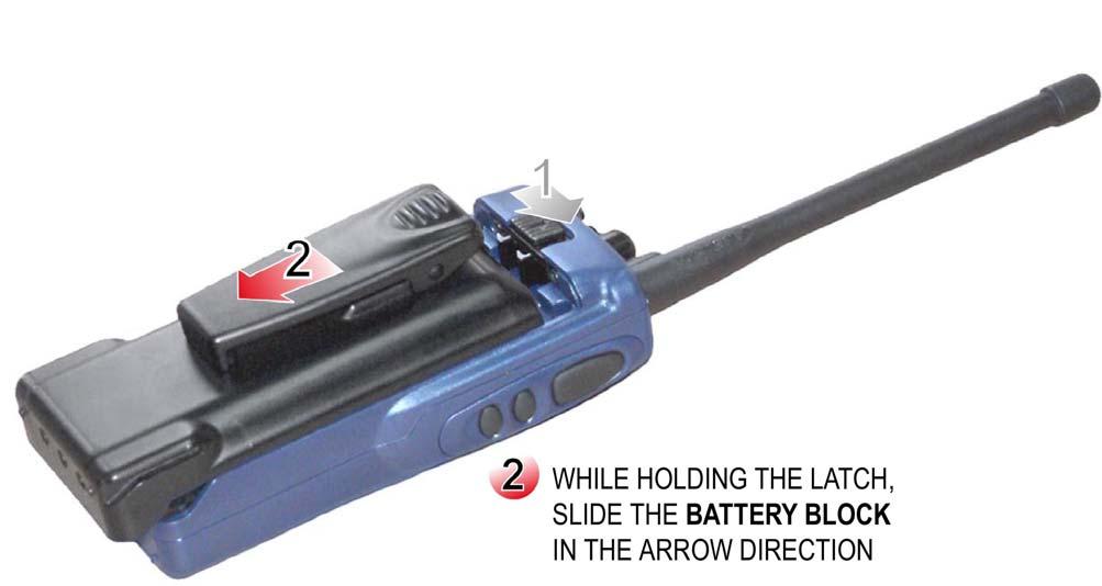
41 5 HOW TO USE Be sure that antenna and battery block is connected truly before turning on the radio. Turn on the radio by turning the On/Off-Volume Switch in the clockwise direction. Enter the attached CIK unit's PIN code. Adjust the volume to required level by using On/Off-Volume Switch. Channel switch is turned to the required channel. Radio is waited to be registered to the channel through system. To make transmission PTT Button is pressed and it is hold pressed during transmission. LED at the top of the radio lights red during transmission. Output power of the radio can be selected as Low, Medium or High by pressing Mode and Power Change Button. When transmission has finished PTT Button is released to pass receiving position. LED at the top of the radio lights blue during receiving. Radio is turned off by turning On/Off-Volume Switch in the counter-clockwise direction. 5.1 REMOVING AND ATTACHING OF THE BATTERY BLOCK WARNINGS Do not EVER throw batteries to fire. At misusages batteries may release damaging chemical gasses. In this case; DO NOT BREATHE THE SMOKE, LEAVE THAT PLACE AS SOON AS POSSIBLE VENTILATE THE PLACE Misusage of batteries may cause fire and/or explosion. Do not try to open battery block. Battery cells contain electrolyte liquids, which may be damaging for skin and clothes. Do not touch to the crack battery cells with naked hand. 5-1
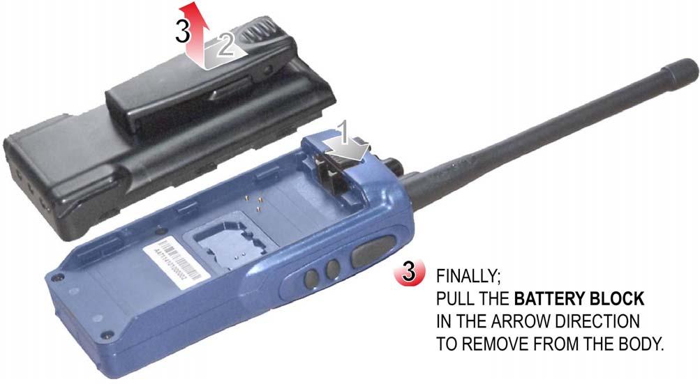
42 Do not short cut + and poles of battery blocks. Making shortcut between poles with metals like paper pincer, screwdriver may cause permanent damage and it may cause fire because of high current capacities of battery blocks. Battery blocks that are not going to be used anymore must be destroyed under appropriate circumstances for environment health. If explosive gasses exit at the atmosphere do not change battery blocks. Touching of the contacts may cause a spark and it may cause an explosion. Battery blocks must be totally discharged before charging them again. Removing and attaching steps of 4700 APCO25 Conventional Handheld Radio battery block is given below: 5-2
43 5-3
44 5.2 MAINTENANCE Radio does not require periodic maintenance. Protect your radio from dust, moisture, dense sun light, extreme heat sources and liquid materials. Use a soft and moistened cloth to clean. Do not use detergent and chemical solvents. 5-4
45 6 SERVED SERVICES TO THE RADIO USERS Basic services that are supported by 4700 APCO25 Handheld Radio are summarized in this section. 6.1 EMERGENCY CALL Radio demands emergency alarm services by this call. If the red button at the top panel of the radio is pressed more than 3 seconds, radio transmits "help" info to the emergency call address (channel), which is determined before. If the call is started at the system channel in the coverage area it is transmitted to the center, if it is started at direct mode caller radio's identity appears at all radios' display and caller radio is warned by an audible alert. To exit from emergency call mode button must be pressed more than 2 seconds. 6.2 GROUP CALL This call is started to a certain group at Digital Crypted Mode. To start group call: * button is pressed and the required group number is dialed, PTT Button is pressed. Call can only be listened by the radios, which are included in the group. 6.3 GENERAL CALL This call is started to all radios at Digital Crypted Mode. To start general call: * * and OK is dialed, PTT Button is pressed. Call can be listened by all radios in the existing channel. 6.4 INDIVIDUAL CALL This call is started to only one radio at Digital Crypted Mode. To start individual call: # # is dialed, 8 digit radio identity to which the individual will be started is dialed, OK' pressed. After establishing an individual call (audible alert is heard and 'INDIVIDUAL' writes at the display) PTT Button must be pressed with in 4 seconds. If both sides do not make transmission in 4 seconds call is terminated. If there is individual call at the channel other radios cannot make transmission. 6.5 CALL ALERT Radio leaves a warning message to another radio to call him back. To start call alert at the authorized radio: # button is pressed 4 times, 8 digit radio identity to which the call alert will be started is dialed, 6-1
46 OK pressed. After the call alert has been transmitted, caller radio's identity appears at the receiver radio's display and an audible alert is heard. 6.6 PHONE CALL Radio demands one-to-one communication at Digital / Crypted Mode by phone call. To start phone call at the authorized radio: # # # is dialed, Required phone number is dialed, OK is pressed. Phone call is made as uni-directional. If PTT Button is pressed, it makes transmission to phone network and if PTT button is released it listens to the broadcast from phone network. Phone call is terminated if phone is closed or button is pressed at radio. 6.7 PRESENT STATUS Radio user's status info can be selected among the status defined at radio. To select status info: # is dialed, Required status info between is entered, OK' is pressed. If radio is turned off and turned on again, status info is deleted. 6.8 SEND STATUS To send active status info to another radio user: 'Send Status' sub menu is selected from Status' menu, Radio ident to which the info will be sent is entered, OK' is pressed. 6.9 STATUS REQUEST To request the status info of a radio under the system: 'Status Request' sub menu is selected from Status menu, Radio ident from which the status info will be requested is entered, OK' is pressed SHORT MESSAGE (SMS) Authorized radio can send maximum 160 characters message, which is entered by keypad to another radio or administration center. Received and sent messages can be seen under 'SHORT MESSAGE' menu. 6-2
47 To send short message: SMS EDIT sub menu is selected from SMS menu, Message (maximum 160 characters) is written by alphanumerical keypad, OK' is dialed and then the radio ident or center number to which the message will be sent is entered is entered, Message is send by pressing OK button PROGRAMMED MESSAGE Radio can send programmed messages, which are determined during programming, to another radio or administration center. Received and send programmed messages can be seen under 'PROGRAMMED MESSAGES' menu. To send programmed message: 'MESSAGE LIST' sub menu is selected under PROGRAMMED MESSAGES, Required message is selected by up, down buttons and 'OK key, Radio ident or center number to which the programmed message will be sent is entered, Programmed Message is send by pressing OK button DATA SERVICES Message, status message transferred and data communication can be achieved by radio ANALOG CALL At analog mode channel, when PTT Button is pressed radio makes transmission through the channel and it gets the analog broadcast at the channel SELECTIVE CALL At analog mode channel, radio starts a call to another radio by dialing selective call number. This call's difference from general call is to warn that user to listen carefully. This call is heard by all radios at the channel. ANI: Radio's identity info. SC: Radio's selective call number. ACK: When radio gets a selective call it sends this number the radio to inform that it has got the call. Against the caller radio ANI number and SC number of the radio that it is calling, called radio responds with its ANI number to inform the caller radio that it has received the call. If selective call is started to a group ACK is not waited. ANI, SC tone sequences are displayed as the talking radios identity. To be abler to make selective call radio must be authorized and at channel parameters, ANI at that channel must be marked. When SC is received by a radio only the caller radio's ANI info appears at the display. 6-3
48 SC number is given to the radios that have selective call property. SC number is a 2-6 digit number and can be selected by programming. Each radios SC number is given by a method that when the last digits are used together it creates a group. In this case groups are obtained with user number 9, 99, 999, 9999, SC started to group means that the call is started to every radios whose SC numbers are starting same. During programming, group tone at group identity entrance is determined as "0" or "A": If group tone is programmed as "0" identity is entered as If group tone is programmed as "A" identity is entered as 22GGG. thus caller radio dials group identity as 22***. To start selective call '#' key is pressed at analog mode and SC number of the other radio is entered at the screen. Call has begun as soon as the all digits are entered. While dialing the SC number, the number at the left side of the cursor is deleted by pressing button TONED CALL At analog mode channel, if channel is being shared by a lot of user, toned call is used to achieve communication of the user groups without listening each other when the channel is not busy. If Tone Code Squelch/Selective Call is disabled by Monitor/Option Button whole communication at the channel can be listened. By tone Code Squelch, tone is added to channel's receiver and transmitter frequencies. Radio receiver only turns on when it gets this tone. Channel tone info is entered with the frequency info during programming REGISTERING Radio must be registered to the system to be able to get service from system channels. After turning on the radio and entering PIN info, radio is registered to the system automatically. Registered site is appeared at the lowest row of the radio's display. If radio get out of the site coverage area and enter another site's coverage area it registered to the new site automatically. Thus user can get service from new system without changing the channel CALLER IDENT Radio displays the caller radio's system ident at system or direct mode digital channels; at analog channels it displays the caller radio's ANI number. For analog ANI display, radio ANI display must be programmed to the radio REPEAT CALL If call short message can not be sent because of a barrier it has repeated for 4 times to establish communication CHANNEL MODE ACCESS Radio user can follow the call that is has transmitted/received is digital/crypted from display. 6-4
49 6.20 CHANNEL SCAN When the radio user is at direct mode channel, it can take the other direct mode channels to its scanning list and watch if there is a call at any of them. It checks the direct mode channels that take place in the "channel scanning list" and if there is any broadcast in one channel, let user to listen to that channel. When any call is received it can respond from that channel with in scanning delay period (0-10sec). At the end of the time turns back to its channel and goes on scanning. Channel scan list can be occurred for all 300 channels or a certain part. At analog usages, if there is broadcast in more than one channel 2 leveled priority can be given according to its own priority order. Priority scanning is not valid during digital channels scanning. While communicating at analog mode, if a call has received from priority channels, radio passes to the priority channel. 1 st and 2 nd priority channel can be defined. If channel list becomes longer it will take time to turn back to the first channel to check. Channel scan process is started and ended by pressing scanning button that take place at the front panel. During this process software keys and keypad (except Scan/Delete key) become unfunctional GROUP SCANNING Radio user can listen to the digital/crypted calls received from all groups that it is included or just the group that it exists at the moment according to the group scanning mode. While the group scanning is in use at the 2 nd row of display "*" sign appears near the Group Number SHORT CUT All software, hardware, usage info about radio takes place at the menus. All menus are supported by numerical short cuts. User can reach the required sub menu by entering its short cut number AUDIBLE ALERTS Radio gives various audible alerts to inform user. Tones and time periods of each alert changes LIGHTING ALERTS Radio gives various lighting alerts to inform user. Red LED lights during transmission, blues LED lights during receiving. According to the usage requires top panel and front panel lighting can be adjusted separately for power save. 6-5
50 6.25 TRANSMISSION TIME OUT To prevent one radio keep busy the channel its transmission time period can be limited. This period is determined during programming up to 255 seconds. And another time period can be determined for same radio that it has to wait before passing transmission again. Thus same radio does not keep busy the channel again for a while. This waiting period can be adjusted during programming between 0-15seconds. Transmission time out is notified by an audible alert and transmission is terminated. And radio does not pass transmission even if its PTT button is pressed, if waiting time period before making transmission again had been defined BUSY CHANNEL LOCK Busy Channel Lock is used to prevent radio passing transmission if there is a broadcast in the channel. Radio that has busy channel lock cannot pass transmission as long as there is a broadcast at the channel DTMF At analog mode if radio's alphanumerical keys are pressed during transmission, radio can produce DTMF tones. But "DTMF transmission authority" must have been given to the radio during programming. Radio can not make DTMF receive process SELECTING CHANNEL Radios that have keypad select 300 channels by keypad. First 15 channels can be selected by Channel Switch. For bigger channels, Channel Switch is taken to position 16 and required channel is dialed from keypad. Radio settled to the selected channel after entering channel number and pressing "OK" KEYLOCK To prevent involuntary pressing the keys, keypad becomes unfunctional by key lock. This is achieved by pressing key lock button at the radio. If the same button and "UNLOCK" key is pressed keypad becomes functional again SIGNAL LEVEL Received signal level is shown by bars. Besides, its value can be read as dbm from Radio Info / Measurement sub menu. User can adjust the output power according to the received signal level for power save or it can learn if it is outside of the coverage area BATTERY CHARGE LEVEL BB4463 smart battery blocks are used at 4700 APCO25 Conventional Handheld Radios. Charge level of the battery can be seen at the display. And remaining charging level is shown as percentage and Volt at the related menu. 6-6
51 7 SIDE UNITS Description ASELSAN P/N ET VHF APCO25 Conventional Crypted Dark Blue Side units of the handheld radio defined above are defined below. 7.1 ANTENNAS Description ASELSAN P/N Helical Antenna MHz ±2mm VHF Strong Antenna MHz ±2mm VHF Strong Antenna MHz ±2mm VHF Strong Antenna MHz ±2mm UHF Whip Antenna MHz BATTERY BLOCKS Li-Ion Battery Block Ni-Mh Battery Block Description Capacity Type No ASELSAN P/N Ni-Cd 1000mAh BB4463N Ni-Cd with clips 1000mAh BB4463NK Ni-Cd with clips Economical(*) 1000mAh BB4463NKE Ni-MH High Capacity Ni-MH High Capacity with clips 1900mAh BB4463MH mAh BB4463MHK Li-Ion 900mAh BB4463L Li-Ion with clips 900mAh BB4463LK Li-Ion High Capacity Li-Ion High Capacity with clips 1800mAh BB4463LH mAh BB4463LHK (*) If this battery is used, radio does not give any information or alert like remaining capacity etc. Ni-Cd, Ni-MH and Li-Ion batteries are optional. Battery blocks must be fully charged before first usage. Especially at Ni-MH and Ni-Cd battery block usages, batteries must be recharged after they are fully discharged. Ni-MH and Ni-Cd battery blocks reach their full capacity after a few charge-discharge processes. When discharge period has arrived, user warned by an alert at the display. Batteries must be discharged by SC4441 desktop charger. 7-1


52 7.3 BATTERY BLOCK CLIPSES Description ASELSAN P/N Battery Block Clips Standard S Battery Block Clips L Battery Block Clips XL CHARGER ASELSAN approved battery blocks that can be used with the SC4451 Charger are given in 'Battery Blocks' section. And the ASELSAN approved power adapters that can be used with the SC4451 Charger are given in the table below: Type No Description ASELSAN P/N SC4451 Desktop Charger Unit AC4451 Vehicle Charger Unit Charger Adapter
53 Ni-Cd, Ni-MH and Li-Ion battery blocks, which have different capacities can be charged while they are attached to the radio or removed from radio. Charger operates according to the fast-charging technique. After the battery has been charged, it passes to the buffer charging. While a smart battery is attached to the charger, it gives information about the situation (charge has began, charging is going on, charging has finished, discharging has started, discharging is going on, short circuit, maintenance required, error etc.) by the lighting alerts. Charging or discharging process can be selected. Attached battery block can be charged after it is fully discharged. Charging current is limited by electronic circuits for protection. Desktop Charger Unit LED alerts are given in Table 7-1. Table 7-1: Desktop Charger LED Warnings LED COLOR EXPLANATION Red (Continuously) Battery block is at fast charge * Red Continuously, sometimes green Charging process is about to finish (>%90) Green (Continuously) Charging has finished (Ni-Cd, Ni-MH ->Buffer Charge) (Battery is full>%95) Orange (Continuously) Battery block and charger connection error ** Red (Blinks) Battery block temperature is not suitable for fast charging. When the battery temperature comes to the suitable value range *** device passes to fast charging automatically. Red Continuously, sometimes orange This alert goes on for about 3 minutes. Battery must be discharged for maintenance (Ni-Cd and Ni-MH batteries only). Red-Green (in order) This alert goes on for 2-10 seconds after the battery is being attached and removed from charger. At this case if battery is replaced to the charger, discharging has begun (Ni-Cd and Ni-MH batteries only).**** Green (Blinks) Discharging (process is being started by the user). Except Li-Ion batteries. Orange (Blinks) Battery is failed. Battery couldn't reach to the required voltage value or there is short circuit between cells. There may also be a disconnection at the positive end of the battery.***** * : Because of block-temperature-control fast charge is applied to Ni-Cd or Ni-MH battery block after 3 minutes the replacing the battery to the charger is the conditions are appropriate. ** : A permanent failure had been occurred at the battery block circuits, unapproved or unprogrammed battery. *** : Starting fast charge temperature range can change according to the battery type. **** : If battery is replaced to charger at first and then removed from charger with in 2-10 seconds to start discharge process, LED begins to blink red-green. To start discharging battery is replaced to the charger again. ***** : This situation occurs at the battery which hadn't been used for long time and thus couldn't reach to the normal voltage level or at the short circuit occurred battery blocks after 20 minutes. It also occurs at the battery whose positive end connection has broken, as soon as the battery is placed to the charger. 7-3

54 7.5 CIK UNIT CIK Unit must be replaced to the socket (Figure 7-2) at the rear face of front panel between front panel and body before getting start to use handheld radio. Otherwise radio will be unfunctional. Figure 7-1: CIK Unit Figure 7-2: Handheld Radio CIK Socket 7-4


55 7.6 ACCESSORIES Accessories that will be used with the 4700 APCO25 Conventional Handheld Radio are given below: ACCESSORY ASELSAN P/N Handheld Microphone Set ( ) Inner Helmet Microphone-Earlap Set-PTT Tube Security Packet Tube Helmet Set Collar Microphone/Earlap Set VIP Ring Microphone/PTT-Earlap Set Tube Throat Microphone-Earlap Set Ear Top Band Helmet Set Tactical Helmet Set Acrobat-Earlap/Microphone Set Tube Ordinary Earlap Microphone/PTT Set Ear Top Ordinary Earlap Microphone/PTT Set Palm security Kit Wireless Earlap Microphone Set Handheld Microphone Set Conversations can be heard through this microphone set. Broadcast is transmitted by PTT Button that takes place at the set and microphone. It is connected to the radio by spiral cable. ( ) 7-5

 7.6.3 Tube Security Packet Loudspeaker is placed into the ear.")
56 7.6.2 Inner Helmet Microphone-Earlap Set User put this set on to his head. Headphones are passing beyond the ears at both sides. Metal connecting headphones stay at the back of the neck. Loudspeaker and microphone take place at one cable, PTT that is in the shape of ring take place at another cable. ( ) Tube Security Packet Loudspeaker is placed into the ear. This part goes over to the attachment piece by a transparent colored spiral cable. PTT that is in the shape of ring take place at another cable. Microphone is attached to the clothes with a cable. ( ) 7-6


57 7.6.4 VIP Ring Microphone/PTT-Earlap Set Loudspeaker part is paced into the ear. PTT that is in the shape of ring is at another cable. Microphone ring is at the PTT. ( ) Tube Throat Microphone-Earlap Set Loudspeaker is placed into the ear. This part goes over to the clothes attachment piece by a transparent colored spiral cable. Microphone is at the elastic band, which wraps up the throat. ( ) Tactical Helmet Set User put this set on to his head. Microphone comes through the user mouth; headphones come across to the ears at both side. Microphone can be adjusted by twisting. Microphone and loudspeaker is connected to a cable. PTT that is in the shape of ring connected to the radio through another cable. ( ) 7-7
PROFESSIONAL DIGITAL TWO-WAY RADIO SYSTEM MOTOTRBO DP 3600/DP 3601 DISPLAY PORTABLE QUICK REFERENCE GUIDE
 PROFESSIONAL DIGITAL TWO-WAY RADIO SYSTEM MOTOTRBO DP 3600/DP 3601 DISPLAY PTABLE QUICK REFERENCE GUIDE m DP 3600/3601 Portables Quick Reference Guide Important Safety Information Product Safety and RF
SYN-TECH III PRODUCTS. Portables. mobiles. Desktop base station
 SYN-TECH III PRODUCTS Portables mobiles Desktop base station WWW.MIDLANDRADIO.COM SYN-TECH III HIGH DEGREE OF CAPACITY ABILITY TO STAY CURRENT ACHIEVING GREATER VERSATILITY RELIABLE COMMUNICATIONS INTELLIGENT
4900 ATLAS Radio Family.
 4900 ATLAS Radio Family www.aselsan.com.tr ATLAS RADIOFAMILY PORTABLE MOBILE DESKTOP 4900 ATLAS Radio Family Atlas Portable Radio The world s first radio having an integrated map application With its various
Midland Syn-Tech III P25 Mobile Radio
 Midland Syn-Tech III P25 Mobile Radio PREFACE Thank you for purchasing a Midland Syn-Tech III P25 Mobile Radio. Properly used, this product will give you many years of reliable service. To get the most
Content. Maintenance. Features ENGLISH. 1 transceiver 1 antenna 1 battery pack 1 belt clip 1 fast desktop charger User manual
 ENGLISH Content 1 transceiver 1 antenna 1 battery pack 1 belt clip 1 fast desktop charger User manual If any items are missing, contact your dealer. Maintenance Your Two Way Radio is an electronic product
SECTION III OPERATION
 SECTION III OPERATION 3.1 INTRODUCTION This section contains information concerning the operation procedures for the BK Radio GPH Flex Mode Series handheld VHF radios. Information on installation and programming
Prodigi TM RDR2000 Series Professional Digital Two-Way Radio Instruction Manual
 1 Congratulations and Thank You for selecting the PRODIGI RDR2000 Series portable two-way radio from RCA Communications Systems - The most trusted name in radio! Our newest digital series professional
OPERATING GUIDE OPERATING GUIDE FOR IC-F5060/F6060 SERIES BIIS 1200/MDC 1200 SYSTEM/ LTR /IDAS NXDN OPERATION
 OPERATING GUIDE OPERATING GUIDE FOR IC-F060/F6060 SERIES BIIS 100/MDC 100 SYSTEM/ LTR /IDAS NXDN OPERATION IMPORTANT Thank you for purchasing this Icom transceiver. The BIIS 100/MDC 100 system/ltr /IDAS
CAT-260 Repeater Controller Computer Automation Technology, Inc
 CAT-260 Repeater Controller Computer Automation Technology, Inc 7378 W. Atlantic Blvd. #239 Margate, Florida 33063 Phone: (954) 978-6171 Fax: (561) 465-5891 Internet: http://www.catauto.com Table of Contents
OPERATING GUIDE OPERATING GUIDE FOR IC-F5060/F6060 SERIES BIIS 1200/MDC 1200 SYSTEM/ LTR /IDAS OPERATION
 OPERATING GUIDE OPERATING GUIDE FOR IC-F060/F6060 SERIES BIIS 100/MDC 100 SYSTEM/ LTR /IDAS OPERATION IMPORTANT Thank you for purchasing this Icom transceiver. The BIIS 100/MDC 100 system/ltr /IDAS (Icom
Introduction Mechanical radio operation... 12
 Operation Manual Contents Introduction... 5 Purpose of application notes...5 Product description...5 Operating frequencies...5 Feature List...5 Warnings...5 Unpacking information...6 Antenna installation...6
BridgeCom Systems D Centimeter DMR and Analog Handheld Transceiver
 Product TechnicalReview Mark by Mark J. Wilson, Spencer, K1RO, WA8SME k1ro@arrl.org BridgeCom Systems D-500 70-Centimeter DMR and Analog Handheld Transceiver This solid radio offers an easy entry point
TX4400 UHF CB RADIO INSTRUCTION MANUAL TX4400 INSTRUCTION MANUAL PAGE 1
 TX4400 UHF CB RADIO INSTRUCTION MANUAL TX4400 INSTRUCTION MANUAL PAGE 1 TABLE OF CONTENTS GENERAL................................... 3 FEATURES.................................. 3 BASIC OPERATION...4 Front
BridgeCom Systems D-500 DMR Radio by Tekk. BridgeCom Systems, Inc D-500 DMR Radio by Tekk
 BridgeCom Systems, Inc D-500 DMR Radio 1 Contents Safety and Overview...3 TEKK D-500 Specifications...4 Unpacking Charging The Battery...5 Getting Acquainted...6 Basic Operations...8 Power On/Off...8 VOL
MTH650. TETRA Portable Terminal Basic User Guide D41-A
 MTH650 TETRA Portable Terminal Basic User Guide 6866537D41-A 19 20 21 1 18 2 17 (b) 3 16 4 17 (a) 15 (a and b) 14 13 12 5 6 7 8 11 9 10 Contents Safety Information............................. 3 MTH650
Instruction Manual PMR-101TX. Private Mobile Radio. TTI Tech. 446MHz, 8 Channels
 PMR-101TX Instruction Manual Private Mobile Radio 446MHz, 8 Channels? 38 CTCSS Sub Tone? 8 Channels? VOX Mode? Scanning? Monitor? Key Pad Lock? Dual Watch? Auto Power Save Mode? Battery Status Indicator?
DP 3600 / DP 3601 Display Portable
 Professional Digital Two-Way Radio System DP 3600 / DP 3601 Display Portable User Guide Contents This User Guide contains all the information you need to use the MOTOTRBO Series Portables. Important Safety
GP329 PLUS AND GP339 PLUS PROFESSIONAL PORTABLE RADIOS
 GP329 PLUS & GP339 PLUS PROFESSIONAL PORTABLE RADIOS MOTOROLA GP329 PLUS AND GP339 PLUS THE SMALL AND COMPACT GP329 PLUS RADIO The GP329 Plus radio is the simple two-way radio solution for professionals
Professional Communications Repeater Family.
 Professional Communications Repeater Family www.aselsan.com.tr Professional Communications Repeater Family 4700 FIXED TYPE 4700 MODULAR MOBILE 4700 COMPACT MOBILE 4900 FIXED TYPE 4900 MOBILE 4700 Fixed
RMV25 / RMV50 RMU25 / RMU45
 RMV25 / RMV50 RMU25 / RMU45 Owner's Manual TABLE OF CONTENTS INTRODUCTION... 3 FCC Requirements... 3 SAFETY WARNING INFORMATION... 3 CONTROLS and INDICATORS... 5 FRONT PANEL... 5 LCD Icons and Indicators...
Pair of PMR446 Two-Way Personal Radios Model: TP391
 Pair of PMR446 Two-Way Personal Radios Model: TP391 USER MANUAL MANUALE D USO MANUEL DE L UTILISATEUR BEDIENUNGSANLEITUNG MANUAL DE USUARIO MANUAL DO USUÁRIO HANDLEIDING BRUKSANVISNING P/N:086L004722-016
AT RF20 MultiBand Handheld Transceiver
 AT RF20 MultiBand Handheld Transceiver AT RF20 MultiBand Handheld Transceiver AT RF20 ECCM handheld multiband transceiver with improved resistance to electronic warfare is designated for use at the lowest
GM339 & GM399 - Select V Mobile Radio Versatility & Sophistication on the Move
 GM339 & GM399 - Select V Mobile Radio Versatility & Sophistication on the Move Motorola GM339 & GM399 Select V Mobile Radios GM339 Versatility on the go GM399 Sophistication on the move In a rapidly changing
Commercial Analogue Series VX-450, VX-4600 and VXR-9000
 Commercial Analogue Series VX-450, VX-4600 and VXR-9000 Meets the following standards: AS/NZS4295, ISO9001 and ISO4001 Commercial Analogue Series VX-450, VX-4600 and VXR-9000 Durable on-the-job responsiveness
OPERATING MANUAL Series. FM Portable Radio. Intrinsically-Safe SMARTNET, SmartZone Conventional
 7700 Series OPERATING MANUAL FM Portable Radio Intrinsically-Safe SMARTNET, SmartZone Conventional 1 LAND MOBILE PRODUCT WARRANTY - The manufacturer s warranty statement for this product is available
ALAN 777 PMR 446 Radio Set User manual
 ALAN 777 PMR 446 Radio Set User manual The all new ALAN 777 represents the very latest and most advanced technology currently available on the PMR446 and LPD market. With its stylish lines and modern design,
Yaesu FT-25R 2-Meter Handheld Transceiver
 Yaesu FT-25R 2-Meter Handheld Transceiver Reviewed by Dan Wall, W1ZFG ARRL LoTW Administration w1zfg@arrl.org The latest entry into the field of small, inexpensive handhelds is the Yaesu FT-25R. This is
OPERATING GUIDE OPERATING GUIDE FOR IC-F3160/F4160 SERIES BIIS 1200/MDC 1200 SYSTEM/ LTR /IDAS NXDN OPERATION
 OPERATING GUIDE OPERATING GUIDE FOR IC-F160/F4160 SERIES BIIS 100/MDC 100 SYSTEM/ LTR /IDAS NXDN OPERATION IMPORTANT Thank you for purchasing this Icom transceiver. The BIIS 100/MDC 100 system/ltr /IDAS
PROFESSIONAL DIGITAL TWO-WAY RADIO SYSTEM MOTOTRBO XPR SERIES CONNECT PLUS DISPLAY PORTABLE USER GUIDE
 PROFESSIONAL DIGITAL TWO-WAY RADIO SYSTEM MOTOTRBO XPR SERIES CONNECT PLUS DISPLAY PTABLE USER GUIDE Declaration of Conformity This declaration is applicable to your radio only if your radio is labeled
BASIC USER GUIDE BASIC USER GUIDE CONTENTS. GeneralInformation... 2
 GP360 GP360 1 2 7 8 12 3 4 5 9 10 11 13 6 CONTENTS GeneralInformation... 2 Operation and Control Functions..... 2 Radio Controls...................... 2 Audio Signal Tones.................. 3 Programmable
Instruction Manual CS800 Mobile Radio
 Instruction Manual CS800 Mobile Radio (This is a revised Version of the CSI Manual. The Information contained was created by Independent Radio Operator. Connect Systems does not have any responsibility
XU/XV-100 Series User Manual
 XU/XV-100 Series User Manual This device complies with Part 15 of FCC Rules. Operation is subject to the following two conditions: This device may not cause harmful interference, and 2) This device must
VX-4100/4200SERIES. VHF/UHF Mobile Radios
 VX-4100/4200SERIES VHF/UHF Mobile Radios HIGH POWER OUTPUT (50W VHF/45W UHF) WIDE FREQUENCY SPAN 134-174 MHz (VX-4104/4204) 400-470 MHz / 450-520 MHz (VX-4107/4207) 501 CHANNELS/32 GROUPS (VX-4200 SERIES)
DJ-MD5 PC Software Guidance
 DJ-MD5 PC Software Guidance Ver, 1.00 2018/08/16 1 Appendix I Public... 4 1. Channel... 4 1 Frequency, call type, power... 4 2 Digital Channel Setting... 5 3 Analog Channel Setting... 6 2. Zone... 7 3.
OWNER S MANUAL FM HANDHELD TRANSCEIVER
 , OWNER S MANUAL RPU4200A FM HANDHELD TRANSCEIVER NOTE, OWNER S MANUAL RPU4200A FM HANDHELD TRANSCEIVER We are very grateful for your purchasing brand twoway radios produced by Relm Wireless Corporation.
DC Instruction Manual. Professional FM Transceiver
 DC-1074 Professional FM Transceiver Instruction Manual Use of the citizen band radio service is licensed in Australia by ACMA Radiocommunications (Citizen Band Radio Stations) Class Licence and in New
FM HANDHELD TRANCEIVER. Connect Systems Incorporated 1802 Eastman Ave., Suite 116 Ventura CA Version 1.00
 CS2010 AND CS2011 PROGRAMMING REFERENCE MANUAL FM HANDHELD TRANCEIVER Connect Systems Incorporated 1802 Eastman Ave., Suite 116 Ventura CA 93003 Version 1.00 Copyright 2010 by Connect Systems Incorporated
Instruction Manual. Model: TX-446. Tech Private Mobile Radio (PMR)446MHz
446MHz") Instruction Manual Tech Private Mobile Radio (PMR)446MHz Model: TX-446 TTI TECH CO., LTD. Eundo Bldg, 737-19, Banpo-1dong, Seocho-ku, Seoul, Korea, 137-041 http://www.ttikorea.co.kr TABLE OF CONTENTS 1.
Instruction Manual Tech Private Mobile Radio (PMR)446MHz Model: TX-446 TTI TECH CO., LTD. Eundo Bldg, 737-19, Banpo-1dong, Seocho-ku, Seoul, Korea, 137-041 http://www.ttikorea.co.kr TABLE OF CONTENTS 1.
Instruction Manual CS800 Mobile Radio
 Instruction Manual CS800 Mobile Radio (This is a revised Version of the CSI Manual. The Information contained was created by Independent Radio Operator. Connect Systems does not have any responsibility
GETTING STARTED. Radio layout. LCD display with icons
 GETTING STARTED Radio layout LCD display with icons 1. Key lock button 2. Battery meter 3. Main channel indicator 4. Scan icon 5. Roger beep indicator 6. CTCSS sub-channel indicator 7. VOX indicator 1
Reference for UV-5R Menus by Jim Unroe - KC9HI 2-April-2014
 Long Name / Description / / Notes / 0 SQL Carrier Squelch Mutes the speaker of the transceiver in the absence of a strong signal. VHF squelch is either OFF or ON. UHF squelch is either OFF or one of 9
GM950 User Guide. GM950 User Guide. Safety Information. English
 GM950 User Guide GM950 User Guide Contents Page: Safety Information... 1 General Information... 2 Radio Controls and Indicators... 2 Audio Signals... 3 Display Icons... 3 Radio On/Off... 3 Channel Selection...
BeeLine TX User s Guide V1.1c 4/25/2005
 BeeLine TX User s Guide V1.1c 4/25/2005 1 Important Battery Information The BeeLine Transmitter is designed to operate off of a single cell lithium polymer battery. Other battery sources may be used, but
G11 I N S T R U C T I O N G U I D E. Midland PMR446 Transceiver
 PMR446 Transceiver G11 I N S T R U C T I O N G U I D E Midland PMR446 Transceiver MIDLAND G11 PMR446 Transceiver Thanks for choosing Midland! G11 is a portable transceiver that is free use in almost all
Commercial Series. CP140 Portable Radio. User Guide
 Commercial Series CP140 Portable Radio User Guide Issue: October 2003 CONTENTS Computer Software Copyrights... 2 Radio Overview..... 3 Operation and Control Functions..... 3 Radio Controls.... 3 LED Indicator.....
*68P81072C40-O* MTX Series Models B5 and B7 Privacy Plus Portable Radios. operating instructions 68P81072C40-O
 *68P8172C4-O* MTX Series Models B5 and B7 Privacy Plus Portable Radios operating instructions 68P8172C4-O 1 MTX Series Models B5 and B7 Privacy Plus Portable Radios Contents Introduction Inspection and
TMR880i technical details
 SCS / Terminals Jan 2013 1(8) TMR880i technical details SCS / Terminals Jan 2013 2(8) TETRA Terminals from CASSIDIAN fulfill the following specifications for TETRA radio equipment in the temperature range
MobileRadio. Owner'sManual
 EMH MobileRadio Owner'sManual TABLE OF CONTENTS Introduction... 1 Basic Operation... 2 Code Guard Operation... 3 EMH Radio Controls... 4 Button Functions... 4 Built-in Features... 7 Keypad Microphone Operation...
INSTRUCTION MANUAL VHF FM TRANSCEIVER TK-2206 UHF FM TRANSCEIVER TK-3206 B (M,M3 )
") INSTRUCTION MANUAL VHF FM TRANSCEIVER TK-2206 UHF FM TRANSCEIVER TK-3206 B62-1763-00 (M,M3 ) 09 08 07 06 05 04 03 02 01 00 THANK YOU We are grateful you chose KENWOOD for your land mobile radio applications.
INSTRUCTION MANUAL VHF FM TRANSCEIVER TK-2206 UHF FM TRANSCEIVER TK-3206 B62-1763-00 (M,M3 ) 09 08 07 06 05 04 03 02 01 00 THANK YOU We are grateful you chose KENWOOD for your land mobile radio applications.
TK-272G/372G. Strength & Durability
 TK-272G/372G A Starring Role in Every Situation, Every Application Get a flying start with Kenwood's TK-272G/372G - tough portables that offer top performance, operating ease and versatility. Intergrated
PROFESSIONAL DIGITAL TWO-WAY RADIO SYSTEM. MOTOTRBO XiR M8220/ XiR M8228 NUMERIC DISPLAY MOBILE USER GUIDE
 PROFESSIONAL DIGITAL TWO-WAY RADIO SYSTEM MOTOTRBO XiR M8220/ XiR M8228 NUMERIC DISPLAY MOBILE USER GUIDE Contents This User Guide contains all the information you need to use the MOTOTRBO XiR Series
GM600 User Guide. GM600 User Guide. English. Contents
 GM600 User Guide GM600 User Guide Contents Page: General Information...2 Radio Care...2 Safety Information...2 Radio Controls...3 Audio Tones...4 Display Icons...4 Display...5 Getting Started...5 Turning
SUMMIT DM MULTI-NET MOBILE RADIO OPERATING MANUAL
 SUMMIT DM MULTI-NET MOBILE RADIO OPERATING MANUAL SAFETY INFORMATION Proper operation of this radio will result in user exposure below the Occupational Safety and Health Act and Federal Communication Commission
PROFESSIONAL WIRELESS MICROPHONE SYSTEM MANUAL
 PROFESSIONAL WIRELESS MICROPHONE SYSTEM MANUAL Thank you for selecting this wireless microphone system! The newly system uses the latest PLL SYNTHESIZED and IR TECHNOLOGY, they have excellent and skilled
ADDENDUM 1. Bid# , Radio Interoperability System for the Sheriff's Office
 County of El Paso Purchasing Department 500 East San Antonio, Room 500 El Paso, Texas 79901 (915) 546-2048 / Fax: (915) 546-8180 ADDENDUM 1 To: From: All Interested Proposers Claudia Sepulveda, Bid Clerk/Buyer
9/14/2017. APX 4000 Portable Radio. Before You Begin. APX 4000: Introduction. Rensselaer County Bureau of Public Safety 800 MHz Radio User Training
 9/14/2017 Rensselaer County Bureau of Public Safety 800 MHz Radio User Training Portable Radio Before You Begin View the Operations Training Presentation first, it covers: Overview of Rensselaer County
Owner s Manual. Model G-223. GMRS/FRS Radio. FEATURES 22 Channels Scan 22 Key Pad Lock Call Alert Power HI/LO Roger Beep Tone
 Owner s Manual Model G-223 GMRS/FRS Radio FEATURES 22 Channels Scan 22 Key Pad Lock Call Alert Power HI/LO Roger Beep Tone This device complies with Part 15 of the FCC rules. Operation is subject to the
GTX Mobile Radio User Guide page. GTX Mobile Radio. 68P02946C75-A page 1
 User Guide page page 1 page 2 GENERAL INFORMATION With the GTX mobile radio you have made an excellent choice. Your GTX mobile radio has left our factory only after extensive tests. D A N G E R When installing
GM350 User Guide. GM350 User Guide. Safety Information. English
 GM350 User Guide GM350 User Guide Contents Page: Safety Information...1 General Information... 2 Radio Controls/Indicators... 2 Audio Signals... 3 Display Icons...3 Radio On/Off...3 Channel Selection...
MIDLAND PROGRAMING G14
 MIDLAND PROGRAMING G14 1. PROGRAMMING CAPABILITY Welcome to the MIDLAND Programming software! It s a programming software specifically designed for G14 and must be used in conjunction with the dedicated
Motorola s Smallest Professional Radio. Compact, Easy to Use & Versatile. GP328 Plus & GP338 Plus Professional Portable Radios
 Motorola s Smallest Professional Radio Compact, Easy to Use & Versatile GP328 Plus & GP338 Plus Professional Portable Radios Compact, Light & Rugged GP328 Plus & GP338 Plus Compact, Light and Rugged Instant
TABLE OF CONTENTS. Keypad Programming Manual 1
 TABLE OF CONTENTS How To Program Radios...2 Keypad Programming...2 A. Navigation...3 1. Group Parameters (CH 00)...4 2. Channel Parameters (CH 01 - CH20)...4 3. Global Parameters (GRP 00)...5 B. Group
OPERATING GUIDE OPERATING GUIDE FOR IC-F3160/F4160 SERIES BIIS 1200/MDC 1200 SYSTEM/ LTR /IDAS OPERATION
 OPERATING GUIDE OPERATING GUIDE FOR IC-F160/F4160 SERIES BIIS 100/MDC 100 SYSTEM/ LTR /IDAS OPERATION IMPORTANT Thank you for purchasing this Icom transceiver. The BIIS 100/MDC 100 system/ltr /IDAS (Icom
Walkie-Talkie. User Manual and Instruction. Getting Started
 Walkie-Talkie User Manual and Instruction Getting Started Installing the AA Batteries Your radio uses 3 AA Alkaline batteries. 1. With the back of the radio facing you, lift the battery latch up to release
TWO-WAY RADIO. Þ ß Ô ² ú RPV516/RPU416. Owner's Manual
 TM TWO-WAY RADIO Þ ß Ô ² ú RPV516/RPU416 Owner's Manual Thank you! We are grateful that you choose RELM for your land mobile applications. We believe this easyto-use transceiver will provide dependable
INSTRUCTION MANUAL VHF FM TRANSCEIVER TK-7102H UHF FM TRANSCEIVER TK-8102H KENWOOD CORPORATION B (M)
") INSTRUCTION MANUAL VHF FM TRANSCEIVER TK-7102H UHF FM TRANSCEIVER TK-8102H KENWOOD CORPORATION B62-1596-00 (M) 09 08 07 06 05 04 03 02 01 00 THANK YOU! We are grateful you chose KENWOOD for your personal
INSTRUCTION MANUAL VHF FM TRANSCEIVER TK-7102H UHF FM TRANSCEIVER TK-8102H KENWOOD CORPORATION B62-1596-00 (M) 09 08 07 06 05 04 03 02 01 00 THANK YOU! We are grateful you chose KENWOOD for your personal
Professional Series. Two-Way Radios and Accessories CDM1550 LS+ VHF. UHF 200 MHz 700 MHz
 Professional Series Two-Way Radios and Accessories CDM1550 LS CDM1550 LS+ VHF UHF 200 MHz 700 MHz TAKING TWO-WAY COMMUNICATION FARTHER THAN EVER. CDM1550 LS with LTR Trunking Motorola Two-Way Radios: The
WIRES-X Portable Digital Node Function. Instruction Manual
 Wide-Coverage Internet Repeater Enhancement System WIRES-X Portable Digital Node Function Instruction Manual Please read this Instruction Manual carefully for appropriate procedure. Preparation Procedure
BX SERIES HANDHELD RADIOS COMMERCIAL INSTRUCTION MANUAL BX SERIES HANDHELD INSTRUCTION MANUAL PAGE 1. Instruction manual includes models:
 COMMERCIAL BX SERIES HANDHELD RADIOS Instruction manual includes models: BX710 BX720 BX730 INSTRUCTION MANUAL BX SERIES HANDHELD INSTRUCTION MANUAL PAGE 1 WARNING - SAFETY INFORMATION The BX Series are
SMARTNET /SMARTZONE TRUNKED. MOTOTRBO ATS 2500i XiR P8260/ XiR P8268 DISPLAY PORTABLE USER GUIDE
 SMARTNET /SMARTZONE TRUNKED MOTOTRBO ATS 2500i XiR P8260/ XiR P8268 DISPLAY PTABLE USER GUIDE Contents This User Guide contains all the information you need to use the MOTOTRBO XiR Series Portable Radios.
INSTRUCTION MANUAL FM HANDHELD TRANSCEIVER
 INSTRUCTION MANUAL PT558 FM HANDHELD TRANSCEIVER NOTE INSTRUCTION MANUAL PT558 FM HANDHELD TRANSCEIVER We are very grateful for your purchasing brand twoway radios produced by Kirisun Electronics (Shenzhen)
New Product Release Information TK-2406M TK-3406M2. VHF FM Transceiver UHF FM Transceiver. March SCHEDULE
 New Product Release Information TK-2406M TK-3406M2 VHF FM Transceiver UHF FM Transceiver March 2013 TK-2406M TK-3406M2 1. SCHEDULE Mass Production TK-2406 M March 2013 TK-3406 M2 March 2013 1 2. MAIN FEATURES
VHF Transceiver AR6201-(X0X) Software Versions: SCI1050S305 Version 3.05 SCI1051S305 Version 1.49 and upwards
 Software Versions: SCI1050S305 Version 3.05 SCI1051S305 Version 1.49 and upwards") VHF Transceiver AR6201-(X0X) Software Versions: SCI1050S305 Version 3.05 SCI1051S305 Version 1.49 and upwards Operating Instructions Issue 5 / November 2013 Article No. 0618.764-071 Becker Avionics GmbH
VHF Transceiver AR6201-(X0X) Software Versions: SCI1050S305 Version 3.05 SCI1051S305 Version 1.49 and upwards Operating Instructions Issue 5 / November 2013 Article No. 0618.764-071 Becker Avionics GmbH
Instruction Manual. Digital Two-way Radio
 II FP520 Digital Two-way Radio We are very grateful for your purchasing KIRISUN brand two-way radios produced by Kirisun Communications Co., Ltd. We believe KIRISUN two-way radio, which always incorporates
TMR880i technical details
 SCS / Terminals October 2013 1(8) TMR880i technical details SCS / Terminals October 2013 2(8) TETRA Terminals from CASSIDIAN fulfill the following specifications for TETRA radio equipment in the temperature
Battery Informationy/Antenna and Other Accessories Charging the Battery
 Thank You Thank you for your purchase of HYT portable two-way radio. HYT portable radios will provide you with clear and reliable communications in high efficiency. Please read this manual before your
WIRES-X Portable Digital Node Function. Instruction Manual
 Wide-Coverage Internet Repeater Enhancement System WIRES-X Portable Digital Node Function Instruction Manual Please read this Instruction Manual carefully for appropriate procedure. Preparation Procedure
Important Charging Information
 Custom Settings TAIT ORCA 5020 CONVENTIONAL Function Key Settings Short Press Long Press F1: F2: F3: Ext1: Ext2: Handset Mode Volume Keys Volume Up: Volume Down: Selcall Settings Selcall ID: Commonly Used
B & D Enterprises 1P repeater controller pg 1 INTRODUCTION:
 B & D Enterprises 1P repeater controller pg 1 INTRODUCTION: The 1P is a basic repeater controller. The controller uses low power devices and stores all commands and system status in non-volatile EE prom.
Barrett 950 HF SSB Transceiver Operating and Installation Manual
 Barrett 950 HF SSB Transceiver Operating and Installation Manual Barrett Communications BCM95000/1 Head office: European office: Barrett Communications Pty Ltd Barrett Europe Limited 10 Port Kembla Drive,
INSTALLATION AND OPERATION GUIDE
 VHF Marine Radio RT-311 INSTALLATION AND OPERATION GUIDE Navicom plaisance: Z.A. des Boutries, 78700 Conflans Ste Honorine Tel: 01.39.72.19.90 Fax: 01.39.19.28.98 Navicom Pro: 3, rue J. Cugnot, Z.A.C Petit
TLKR T60 OWNER'S MANUAL EN DE FR IT ES PR NL DA NO TU PL SV RU
 TLKR T60 OWNER'S MANUAL EN DE FR IT ES PR NL DA NO TU PL SV RU SF 1 PRODUCT SAFETY AND RF EXPOSURE FOR PORTABLE TWO-WAY RADIOS! Caution ATTENTION! Before using this product, read the RF energy awareness
PROFESSIONAL DIGITAL TWO-WAY RADIO MOTOTRBO DM4400/DM4401/DM4400e/DM4401e NUMERIC DISPLAY MOBILE USER GUIDE. es-es
 PROFESSIONAL DIGITAL TWO-WAY RADIO MOTOTRBO DM4400/DM4401/DM4400e/DM4401e NUMERIC DISPLAY MOBILE USER GUIDE en de-de fr-fr pl ru ar-eg it-it es-es tr Contents Important Safety Information...8 Software
TK-D740 TK-D740H TK-D740HV TK-D840 TK-D840H TK-D840HU
 TK-D740 TK-D740H TK-D740HV TK-D840 TK-D840H TK-D840HU VHF DIGITAL TRANSCEIVER UHF DIGITAL TRANSCEIVER USER MANUAL B5A 0925-00/01 Contents PREPARATION... 4 Connecting the power cable... 4 Installing the
GP338 PORTABLE RADIO - A VERSATILE RADIO. The Power Tool for Contact & Control
 SPECIFICATION SHEET GP338 PORTABLE RADIO - A VERSATILE RADIO KEY FEATURES AND BENEFITS GP338 The Power Tool for Contact & Control X-PAND Audio Technology: Motorola s special voice compression and expansion
ENRICHING YOUR DIGITAL EXPERIENCE NEW MEMBER TO WORLD'S MOST COMPLETE DMR PORTFOLIO PD98X
 ENRICHING YOUR DIGITAL EXPERIENCE NEW MEMBER TO WORLD'S MOST COMPLETE DMR PORTFOLIO PD98X www.hytera.com PD98X Highlight Brand New Features 01 Micro SD Card 02 Single Frequency Repeater Mode Based on micro
UH-040XR Operating Guide
 UH-040XR Operating Guide WARNING! Do not operate the transmitter of any radio equipment unless all the Radio Frequency (RF) connectors are secured and any open connectors are properly terminated. Do not
VHF Transceiver AR6201
 VHF Transceiver AR6201 Operating Instructions Issue 2 / October 2010 Article No. 0618.764-071 Becker Flugfunkwerk GmbH Baden-Airpark B 108 77836 Rheinmünster Germany Telefon / Telephone +49 (0) 7229 /
MOTOROLA MOTOTRBO CAPACITY PLUS RADIO SYSTEM DESCRIPTION
 MOTOROLA MOTOTRBO CAPACITY PLUS RADIO SYSTEM DESCRIPTION P a g e 1 North Lawrence Community Schools October 1, 2012 P a g e 2 Table of Contents TABLE OF CONTENTS... 2 GENERAL SYSTEM OVERVIEW... 3 REQUIRED
If any item is missing or have been damaged during the shipment, please notify your MIDLAND dealer.
 Content 1 CT 790 transceiver 1 high gain antenna 1 Li-ion battery pack 1 desktop charger 1 belt clip 1 hand strap If any item is missing or have been damaged during the shipment, please notify your MIDLAND
TK-2312E TK-3312E. New Product Release Information. VHF FM Transceiver UHF FM Transceiver. March 2011
 New Product Release Information TK-2312E TK-3312E VHF FM Transceiver UHF FM Transceiver March 2011 We are pleased to send you product information on our new VHF and UHF FM Portable Transceivers, the TK-2312E
CS2000 AND CS2001 USERS MANUAL FM HANDHELD TRANCEIVER. CONNECT SYSTEMS INCORPORATED 1802 Eastman Ave,. Suite 116 Ventura CA VERSION 1.
 CS2000 AND CS2001 USERS MANUAL FM HANDHELD TRANCEIVER CONNECT SYSTEMS INCORPORATED 1802 Eastman Ave,. Suite 116 Ventura CA 93003 VERSION 1.00 Copyright 2009 by Connect Systems Incorporated GUIDE FOR THOSE
USERS MANUAL TR-710.
 USERS MANUAL TR-710 www.jotron.com EC Declarations of Conformity, available at www.jotron.com Read this Users Manual fully to familiarise yourself with the equipments functions and facilities. Abbreviations
User Manual. High Efficiency Locator Beacon
 User Manual RT-B77 HELB High Efficiency Locator Beacon Edited by: RHOTHETA Elektronik GmbH Kemmelpark Dr.-Ingeborg-Haeckel-Str. 2 82418 Murnau Germany Tel.: +49 8841 4879-0 Fax: +49 8841 4879-15 Internet:
TX670 POCKET SIZE UHF CB RADIO INSTRUCTION MANUAL 2 WATT HANDHELD. TX670 Instruction Manual Page 1
 TX670 POCKET SIZE 2 WATT HANDHELD UHF CB RADIO INSTRUCTION MANUAL TX670 Instruction Manual Page 1 Warning: Safety Information The TX670 is a radio frequency transmitting device. When transmitting, keep
INSTRUCTION MANUAL. 144/ 430 MHz FM DUAL BANDER TH-F7A B (M) FM DUAL BANDER TH-F7
 FM DUAL BANDER TH-F7") INSTRUCTION MANUAL FM DUAL BANDER TH-F7 144/ 430 MHz FM DUAL BANDER TH-F7A B62-1899-00 (M) 09 08 07 06 05 04 03 02 01 00 THANK YOU THANK YOU Thank you for choosing this KENWOOD TH-F7A transceiver. It has
INSTRUCTION MANUAL FM DUAL BANDER TH-F7 144/ 430 MHz FM DUAL BANDER TH-F7A B62-1899-00 (M) 09 08 07 06 05 04 03 02 01 00 THANK YOU THANK YOU Thank you for choosing this KENWOOD TH-F7A transceiver. It has
PROFESSIONAL DIGITAL TWO-WAY RADIO MOTOTRBO DP4800/DP4801 COLOUR DISPLAY PORTABLE USER GUIDE
 PROFESSIONAL DIGITAL TWO-WAY RADIO MOTOTRBO DP4800/DP4801 COLOUR DISPLAY PTABLE USER GUIDE EN DE FR IT ES TU PL RU AR Contents This User Guide contains all the information you need to use the MOTOTRBO
OPERATING GUIDE VHF TRANSCEIVER. Iç-G88
 OPERATING GUIDE VHF TRANSCEIVER Iç-G88 INTRODUCTION PREFACE We appreciate you choosing Icom for your communication needs. The MDC 1200 signaling system is built into your IC-G88 vhf transceiver. IMPORTANT
HR MHZ AM-FM AMATEUR RADIO HF TRANSCEIVER OWNER'S MANUAL. Content of the packaging
 HR-2800 28 MHZ AM-FM AMATEUR RADIO HF TRANSCEIVER OWNER'S MANUAL NOTICE! It is recommended to carefully read this owner s manual before using the product. This will also help to prevent illegal use of
PROFESSIONAL DIGITAL TWO-WAY RADIO MOTOTRBO DP2400 NON-DISPLAY PORTABLE USER GUIDE. fr-fr. it-it
 PROFESSIONAL DIGITAL TWO-WAY RADIO MOTOTRBO DP2400 NON-DISPLAY PORTABLE USER GUIDE en de-de fr-fr it-it es-es tr pl ru ar Contents Important Safety Information...5 Software Version...6 Computer Software