Transmitarrays, reflectarrays and phase shifters for wireless communication systems. Pablo Padilla de la Torre Universidad de Granada
|
|
|
- Diane Walker
- 5 years ago
- Views:
Transcription
1 Transmitarrays, reflectarrays and phase shifters for wireless communication systems Pablo Padilla de la Torre Universidad de Granada
2 Outline 1. Introduction to Transmitarray and Reflectarray structures 2. Passive Transmitarrays 3. Passive Reflectarrays 4. Reconfigurability: Phase shifters 5. Reconfigurable devices: Example 2
3 1. Introduction to Transmitarray and Reflectarray structures 3
4 Txarray and Rxarray structures Transmitarrays Equivalent to artificial lenses Reflectarrays Equivalent to reflector-based antennas Reception and pattern rearrangement. Planar Architecture. Fundamental Aim: Configure a new radiation pattern (passive devices). Reconfigure the radiation pattern (active devices). Different receivers for different signals, depending on DoA Directions of arrival Lens Receiver 1 Receiver k 4

5 Transmitarray structures Transmitarray concept: 1. Phase error correction 2. Radiation pattern modification 5
6 Reflectarray structures Reflectarray concept: 1. Phase error correction 2. Radiation pattern modification 6


7 Reflectarray structures Reflectarray Configuration: Without phase correction: Array distribution: With phase correction: 7
8 2. Passive Transmitarrays 8


9 Passive Transmitarrays Transmitarray configuration: Particular Specifications: Working frequency: 12 GHz. Band width: >0.7 GHz Linear polarization. Geometry Applied: Design 1: Multilayer Planar Geometry Two different geometries analyzed and applied: Design 2: Planar Geometry with plane change 9


10 Passive Transmitarray: Design 1 Transmitarray design: Particular Specifications: 5x5 element array. Array separation between elements: 0.8λ 0. Radiation pattern reconfiguration: 10º tilt in one of the main axes. Transmitarray Cell Design: Transmitarray configuration: Design of one half of Transmitarray cell: Radiating element. Stripline. Coaxial to stripline transmission line. 10


11 db db Passive Transmitarray: Design 1 Design and Prototypes for Subsystems: Half transmitarray cell prototype: Phase delay line: Coaxial to stripline transmission. Stripline. For measurements in the center of cell TRL calibration Kit Prototype: Measurement results: Frequency (GHz) Frequency (GHz) 11


12 Passive Transmitarray: Design 1 Design and Prototypes for Subsystems: Delay line integration Patch array integration Transmission lines Vias Coaxial to stripline transmission. Stripline. Line detail Complete soldered structure Patch array Feeding Horn and hanging elements Complete Prototype 12

13 Passive Transmitarray: Design 1 Prototype Measurement Phase error correction and 10º tilt in one axis. Theoretical and measured radiation pattern Measuring scheme Copolar Measured Gain: 15.4 dbi. Spherical acquisition chamber Near field to far field conversion Reduction due to spillover (accepted horn power 42%=-3.7 db) and circuit losses (1.9dB). 13


14 Passive Transmitarray: Design 2 Transmitarray design: Particular Specifications: 10x10 element array. Stacked patches. Array separation between elements: 0.6λ 0. Radiation pattern reconfiguration: 10º tilt in one of the main axes. Transmitarray cell design: Upper Patch ε r =2.17, h=1.575 mm ε r =1.07, h=2 mm Lower Patch ε r =2.17, h=1.575 mm Ground Plane Design of one half of Transmitarray cell: Stacked patch Radiating element. Coaxial to microstrip transmission line. 90º change in reference plane. Microstrip lines 14


15 Passive Transmitarray: Design 2 Prototypes of Subsystems : Patch prototypes: Single patch measurement results: 0 90º Transition: Half transmitarray cell measurement: Patch + 90º transition+ transmission line: -40 Patch embedded in array: S 11, db -30 S 11, db Frequency (GHz) Frequency (GHz) 15


16 Upper Lower Layer Passive Transmitarray: Design 2 Transmitarray assembly: Patch layers Delay line layers Complete passive transmitarray for the second design Complete Prototype Lines soldering detail Two radiating interfaces. 10x10 array. 100 soldered transmission lines 200 metallic vias. 50x50cm ground plane. 800 soldering points. 16


 3D measured")


17 Passive Transmitarray: Design 2 Prototype Measurement: For Design 2: Phase error correction and 10º tilt in one main axis 0 Theoretical radiation pattern Measured Radiation pattern db Theta (deg) 3D measured radiation pattern 2D measured radiation pattern Spherical acquisition chamber Near field to far field conversion Measured Gain: 22.5 dbi. Reduction due to spillover (accepted horn power 75%=-1.25 db) and transmission line losses (1.05 db) 17
18 3. Passive Reflectarrays 18

19 Array distribution: Passive Reflectarray Circularly polarized Reflectarray: geometry: Rx LHCP/RHCP Tx LHCP/RHCP Shifting circuit layer Ground plane Lower patch layer Upper patch layer x y Reflectarray specifications: Parameter Value Units Frequency bands GHz Polarization LHCP/RHCP - Axial ratio < 2.5 db 3dB beamwidth 7 º Side lobe level < -16 db Cross polarization < -25 db Gain > 25.5 dbi Directivity 27 dbi Radiation efficiency > 65 % VSWR 1.4:1 (-15.6dB) - Size (planar structure) 240x240x3.524 mm Array separation 0.55λ mm Focal distance 210 mm Reflectarray Configuration: z 13x13 cell array. Multilayered square patches. Cell separation: 0.55λ 0. Re-alignement of the radiation pattern towards the broadside direction. ~70% of available power coming from the feeder (spillover efficiency). 19

20 Passive Reflectarray Subsystem prototypes: multilayered patches and phase shifters Isolated cell: Embedded patch in array: Phase shifters: 20


21 Upper layer lower layer Passive Reflectarray Prototyping: Reflectarray assembly Phase shifting layer: Patch layers: Complete assembled prototype: 21

![-60-40 -20 0 20 40 60 80 phase [º] measured CP simulated CP measured XP -30-40 -80-60 -40-20 0](/docs-images/82/86173301/images/22-3.jpg "20 40 60 80 phase [º] 3D Pattern: 2D Pattern: Gain: 26.5 dbi directivity: 28.")
22 Prototype Measurements: Radiation Patterns (at 12GHz): φ=90º (y axis) φ=0º (x axis) Passive Reflectarray [db] measured CP simulated CP measured XP -30 [db] phase [º] measured CP simulated CP measured XP phase [º] 3D Pattern: 2D Pattern: Gain: 26.5 dbi directivity: 28.1 dbi Efficiency: ~68% 22
: 2 [db] 1 Gain: 26.5 dbi directivity: 28.")
23 Passive Reflectarray Prototype Measurements: Radiation Patterns ( GHz): φ=0º (x axis) GHz 11.5GHz 12.5GHz [db] phase [º] Axial Ratio (steering direction): 2 [db] 1 Gain: 26.5 dbi directivity: 28.1 dbi Efficiency: ~68% 0 11,5 11, ,25 12,5 freq. [GHz] 23
24 4. Reconfigurability: Phase shifters 24


25 Towards reconfigurability For reconfigurability: 1- Mechanical variation: feeder movement Some disadvantages: Reduced steering variation. Mechanical controlling 2- Electronic variation: phase variation at the Txarray or Rxarray A- Electronically reconfigurable radiating elements: Advantages: Costs. Tinny space necessary. Withdraws: Control circuit. Crosspolar levels. B- Electronically reconfigurable phase shifters: Advantages: Technologically feasible. Discrete (bits) control. Withdraws: Costs. Number of elements. Control circuit. 25

26 A. Active radiating elements Active Patch Scheme: Expected Behavior: Variation in patch equivalent impedance changes in working frequency changes in the phase behaviour of S parameters. Patch with surface Varactor: Basic equivalent Circuit. 26

27 A. Active radiating elements Simulation Model: Two ways of defining simulations: 1- Complete Simulation with general purpose simulation SW: CST, HFSS, SEMCAD, etc. 2- Simulation with connection of a variety of S parameter boxes, for the different active patch elements. 27
 Simulation results with CST: With Cmax (2.0 pf) 2 nd Model (Boxes model) With Cmin (0.")
28 A. Active radiating elements 1 st Model (Complete model) With Cmin (0.13 pf) Simulation results with CST: With Cmax (2.0 pf) 2 nd Model (Boxes model) With Cmin (0.13 pf) With Cmax (2.0 pf) 28


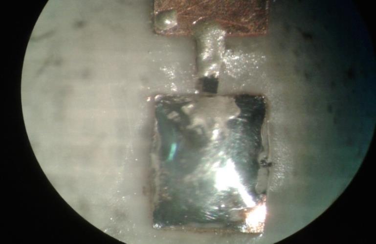
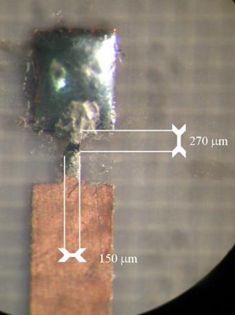
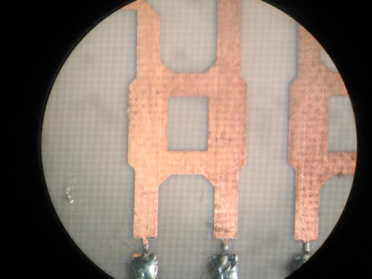
29 A. Active radiating elements Circuit layout Patch Prototype: Some active patch details: Choke Inductance Varactor Decoupling capacitor Patch over substrate with ε r = Unions with conductive epoxy. Varactors for microwave purpose. x6 x10 Reflection scheme: S 11 The phase behaviour is assumed to be twice the phase behaviour considered in a transmission scheme. Measurement Schemes: Transmission scheme: S 12 The phase behaviour of the patch is directly the measured one. 29


30 A. Active radiating elements Reflection model: Transmission model: With Cmin With Cmin With Cmax With Cmax Laboratory Measurements 30
31 A. Active radiating elements Phase Range: Crosspolar Level: To avoid polarization rotation or parasitic polarization (high crosspolar), the connection of the active circuitry is performed in the symmetry axes of the patch. Active Circuitry With the reflection model up to 200º could be achieved in a go and return scheme (100º for each way). Patch Feeding Symmetry line Radiation pattern for 4.5v polarization voltage: With the transmission model, the phase variation decreases (up to 80º, for one way). 31
 Z Z 0 / jx ( V ) 0")
32 B. Active phase shifters Phase Shifter Scheme: Subsystem 1: Directional coupler: Input For Txarray: Output Directional Coupler 3dB - 90º Subsystem 2: Reflective circuit: For Rxarray: Directional Coupler 3dB - 90º Input/Output jx ( V ) Z Z 0 / jx ( V ) 0 32


33 B. Active phase shifters Phase Shifter Design: initial element design 4 port 3dB/90º coupler: Reflective LC circuits: 33
34 For Linearly Polarized Rxarrays: working scheme B. Active phase shifters P (in/out) Hybrid coupler P1 (in) P2 (out 90º) Reflective circuit L C way 1 way 2 way 3 way 4 L C P4 (isolated) Reflective circuit P3 (out 180º) L C Reflective circuit 34
![B. Active phase shifters For Linearly Polarized Rxarrays: reflective circuit varactor printed L printed L varactor Phase Shifter Design: LP integrated design substrate reflective circuits S11 [db]](/docs-images/82/86173301/images/35-2.jpg "0-1 -2-3 Amplitude: via transition coaxial feeding port (input/output) 0.13pF 0.23pF 0.39pF 0.65pF 0.82pF -4 1.16pF 1.51pF 2.2pF -5 11 11.2 11.4 11.6 11.8 12 12.2 12.4 12.6 12.")
35 B. Active phase shifters For Linearly Polarized Rxarrays: reflective circuit varactor printed L printed L varactor Phase Shifter Design: LP integrated design substrate reflective circuits S11 [db] Amplitude: via transition coaxial feeding port (input/output) 0.13pF 0.23pF 0.39pF 0.65pF 0.82pF pF 1.51pF 2.2pF Freq [GHz] S11 [deg] hybrid coupler printed L Phase: varactor ground plane 0.13pF 0.23pF 0.39pF 0.65pF 0.82pF 1.16pF 1.51pF 2.2pF Freq [GHz] 35


36 For Linearly Polarized Rxarrays: LP prototype manufacturing details B. Active phase shifters 36
![For Linearly Polarized Rxarrays: B. Active phase shifters Phase Shifter: LP integrated prototype S11 [db] 0-1 Amplitude: -2 0v 2v 4v -3 6v 8v 10v -4 12v 14v 16v -5 11 11.2 11.4 11.](/docs-images/82/86173301/images/37-2.jpg "6 11.8 12 12.2 12.4 12.6 12.8 13 Freq [GHz] S11 [deg] 0-100 -200-300 -400-500 Phase: -600 11 11.2 11.4 11.6 11.8 12 12.2 12.4 12.6 12.8 13 Freq [GHz] 0v 2v 4v 6v 8v 10v 12v 14v 16v 37")
37 For Linearly Polarized Rxarrays: B. Active phase shifters Phase Shifter: LP integrated prototype S11 [db] 0-1 Amplitude: -2 0v 2v 4v -3 6v 8v 10v -4 12v 14v 16v Freq [GHz] S11 [deg] Phase: Freq [GHz] 0v 2v 4v 6v 8v 10v 12v 14v 16v 37
38 For Circularly Polarized Rxarrays: B. Active phase shifters working scheme Reflective circuit C L Hybrid coupler 2A P4 P3 (180º) Reflective circuits L C P A(in/out) P1 P2 (90º) P1 P2 (90º) L C P B(in/out) P4 P3 (180º) Hybrid coupler 1 P1 P2 (90º) L C P A P B : way 1 way 2 way 3 way 4 C L Reflective circuit P4 P3 (180º) Hybrid coupler 2B L C Reflective circuits 38
![For Circularly Polarized Rxarrays: Phase Shifter Design: CP integrated design B. Active phase shifters Amplitude: Phase: S12 [deg] S12 [db] 0-1 -2 0.13pF 0.23pF 0.39pF -3 0.65pF 0.](/docs-images/82/86173301/images/39-2.jpg "82pF -4 1.16pF 1.51pF -5 11.5 12 2.2pF 12.5 Freq [GHz] 13 13.5-200 -400-600 -800 460º 0.13pF 0.23pF 0.39pF 0.65pF 0.82pF 1.16pF 1.51pF 2.2pF -1000 11.5 12 12.5 13 13.")
39 For Circularly Polarized Rxarrays: Phase Shifter Design: CP integrated design B. Active phase shifters Amplitude: Phase: S12 [deg] S12 [db] pF 0.23pF 0.39pF pF 0.82pF pF 1.51pF pF 12.5 Freq [GHz] º 0.13pF 0.23pF 0.39pF 0.65pF 0.82pF 1.16pF 1.51pF 2.2pF Freq [GHz] 39


40 For Circularly Polarized Rxarrays: CP prototype manufacturing details B. Active phase shifters 40
41 For Circularly Polarized Rxarrays: B. Active phase shifters Phase Shifter: CP integrated prototype Amplitude: Phase: S12 [db] v 2v 4v 6v 8v 10v 12v 14v 16v Freq [GHz] S12 [deg] S12 [deg] GHz Volts 0v 2v 4v 6v 8v 10v 12v 14v 16v 370º Freq [GHz] 41


42 For Linearly Polarized Txarrays: working scheme B. Active phase shifters 42
 Structure replication up to 3")
43 B. Active phase shifters For Linearly Polarized Txarrays: Phase Shifter integrated design: Amplitude: S X1 behaviour versus polarization voltage: Phase response for edge values (mask) Structure replication up to 3 times 43


44 For Linearly Polarized Txarrays: Prototype manufacturing details B. Active phase shifters 44


45 B. Active phase shifters For Linearly Polarized Txarrays: Output Port Phase Shifter measuring results: Varactor Inductive Line Control circuit connection Input Port Coax. to microstrip transition Amplitude: S X1 behaviour versus polarization voltage: GND Connection Hybrid Circuit Z 0 Ω Transmission Line Holes to Ground Plane S 21 Phase: 45
46 5. Example of reconfigurable device: Electronically Reconfigurable Transmitarray 46


47 Electronically Reconfigurable Txarray Transmitarray Scheme: Geometry Applied: Patch grouping by means of bidirectional distribution networks. Constituting elements: Stacked patches: Phase shifters: 12 GHz, BW >0.7 GHz, LP Feeding corrugated horn 6x6 element array. 0,7λ 0 grid. 360º range phase shifters. 2x2 patch groups. Distribution networks: 90º transitions: 47


48 Electronically Reconfigurable Txarray Towards the complete assembly Phase Shifters Verification and Calibration: Average insertion losses: 3.7 db Average Phase Shift: 379º Control voltage range: 0V to16v Pattern modifications in one of the main axes: Plane φ=0º, θ=0º Plane φ=0º, θ=-10º 48


49 Electronically Reconfigurable Txarray Transmitarray assembly: Patch layers Radiating interface Complete electronically reconfigurable Txarray assembled Integration in ground plane Complete Prototype: Two radiating interfaces. 72 radiating elements. 18 distribution networks. 9 complete phase shifters. Detail of inner zone Distribution networks Transmitarray core Shifters integration 49


50 Electronically Reconfigurable Txarray Prototype Measurement: Pattern 1: only phase error correction (all shifters with 0V control voltage). Theoretical radiation pattern Measured Radiation pattern 3D measured radiation pattern 2D measured radiation pattern For prototype validation, two configurations: Pattern 1: only phase error correction (all with 0V control voltage). Pattern 2: phase error correction and reconfiguration of radiation pattern in one of the main axes, applying a 9 degrees tilt. Measured Gain: dbi. Reduction due to spillover (accepted horn power 60%=-2.2 db) and shifter insertion losses (3dB mean value in this configuration. 50


51 Electronically Reconfigurable Txarray Prototype Measurement: Pattern 2: Phase error correction and 9º tilt in one main axis Theoretical radiation pattern Measured Radiation pattern 3D measured radiation pattern 2D measured radiation pattern For prototype validation, two configurations : Pattern 1: only phase error correction Pattern 2: phase error correction and reconfiguration of radiation pattern in one of the main axes, 9 degrees tilt. Measured Gain: 15.1 dbi. Reduction due to spillover (accepted horn power 60%=-2.2 db) and shifter insertion losses (4dB mean value in this configuration). 51
52 Thanks for your attention! 52
53 I. MIMO antenna performance parameters Transmitarrays, reflectarrays and phase shifters for wireless communication systems Pablo Padilla de la Torre Universidad de Granada EI3204 Antenna Theory Course 8-10 May 2017
Design and Demonstration of 1-bit and 2-bit Transmit-arrays at X-band Frequencies
 PIERS ONLINE, VOL. 5, NO. 8, 29 731 Design and Demonstration of 1-bit and 2-bit Transmit-arrays at X-band Frequencies H. Kaouach 1, L. Dussopt 1, R. Sauleau 2, and Th. Koleck 3 1 CEA, LETI, MINATEC, F3854
Broadband electronically tunable reflection-based phase shifter for active-steering microwave reflectarray systems in Ku-band
 Broadband electronically tunable reflection-based phase shifter for active-steering microwave reflectarray systems in Ku-band Pablo Padilla, Juan F.Valenzuela-Valdés Jose Luis Padilla, Jose Manuel Fernández-González
Electronically Reconfigurable Transmitarray at Ku Band for Microwave Applications
 Electronically Reconfigurable Transmitarray at Ku Band for Microwave Applications Pablo Padilla, Alfonso Muñoz-Acevedo, Manuel Sierra-Castañer, Member, IEEE, and Manuel Sierra-Pérez, Senior Member, IEEE
Circularly polarised broadband planar lightweight reflectarray with eligible pattern for satellite communications in Ku-band
 Circularly polarised broadband planar lightweight reflectarray with eligible pattern for satellite communications in Ku-band Pablo Padilla, José Manuel Fernández, José-Luis Padilla, Juan F. Valenzuela-Valdés,
The Basics of Patch Antennas, Updated
 The Basics of Patch Antennas, Updated By D. Orban and G.J.K. Moernaut, Orban Microwave Products www.orbanmicrowave.com Introduction This article introduces the basic concepts of patch antennas. We use
EMG4066:Antennas and Propagation Exp 1:ANTENNAS MMU:FOE. To study the radiation pattern characteristics of various types of antennas.
 OBJECTIVES To study the radiation pattern characteristics of various types of antennas. APPARATUS Microwave Source Rotating Antenna Platform Measurement Interface Transmitting Horn Antenna Dipole and Yagi
Design of Frequency and Polarization Tunable Microstrip Antenna
 Design of Frequency and Polarization Tunable Microstrip Antenna M. S. Nishamol, V. P. Sarin, D. Tony, C. K. Aanandan, P. Mohanan, K. Vasudevan Abstract A novel compact dual frequency microstrip antenna
A Broadband Reflectarray Using Phoenix Unit Cell
 Progress In Electromagnetics Research Letters, Vol. 50, 67 72, 2014 A Broadband Reflectarray Using Phoenix Unit Cell Chao Tian *, Yong-Chang Jiao, and Weilong Liang Abstract In this letter, a novel broadband
A RECONFIGURABLE HYBRID COUPLER CIRCUIT FOR AGILE POLARISATION ANTENNA
 A RECONFIGURABLE HYBRID COUPLER CIRCUIT FOR AGILE POLARISATION ANTENNA F. Ferrero (1), C. Luxey (1), G. Jacquemod (1), R. Staraj (1), V. Fusco (2) (1) Laboratoire d'electronique, Antennes et Télécommunications
with a Suspended Stripline Feeding
 Wide Band and High Gain Planar Array with a Suspended Stripline Feeding Network N. Daviduvitz, U. Zohar and R. Shavit Dept. of Electrical and Computer Engineering Ben Gurion University i of the Negev,
Broadband and High Efficiency Single-Layer Reflectarray Using Circular Ring Attached Two Sets of Phase-Delay Lines
 Progress In Electromagnetics Research M, Vol. 66, 193 202, 2018 Broadband and High Efficiency Single-Layer Reflectarray Using Circular Ring Attached Two Sets of Phase-Delay Lines Fei Xue 1, *, Hongjian
Antenna Theory and Design
 Antenna Theory and Design Antenna Theory and Design Associate Professor: WANG Junjun 王珺珺 School of Electronic and Information Engineering, Beihang University F1025, New Main Building wangjunjun@buaa.edu.cn
A K-Band Flat Transmitarray Antenna with a Planar Microstrip Slot-Fed Patch Antenna Feeder
 Progress In Electromagnetics Research C, Vol. 64, 97 104, 2016 A K-Band Flat Transmitarray Antenna with a Planar Microstrip Slot-Fed Patch Antenna Feeder Lv-Wei Chen and Yuehe Ge * Abstract A thin phase-correcting
CHAPTER 2 MICROSTRIP REFLECTARRAY ANTENNA AND PERFORMANCE EVALUATION
 43 CHAPTER 2 MICROSTRIP REFLECTARRAY ANTENNA AND PERFORMANCE EVALUATION 2.1 INTRODUCTION This work begins with design of reflectarrays with conventional patches as unit cells for operation at Ku Band in
Array antennas introduction
 Array antennas introduction José Manuel Inclán Alonso chema@gr.ssr.upm.es Universidad Politécnica de Madrid (Technical University of Madrid, UPM) Outline Array antennas definition Arrays types Depending
Development of a noval Switched Beam Antenna for Communications
 Master Thesis Presentation Development of a noval Switched Beam Antenna for Communications By Ashraf Abuelhaija Supervised by Prof. Dr.-Ing. Klaus Solbach Institute of Microwave and RF Technology Department
A 5.8-GHz Planar Beam Tracking Antenna Using a Magic-T
 Progress In Electromagnetics Research C, Vol. 76, 159 17, 217 A 5.8-GHz Planar Beam Tracking Antenna Using a Magic-T Rimi Rashid *, Eisuke Nishiyama and Ichihiko Toyoda Abstract This paper proposes a novel
Portable Low Profile Antenna At X Band
 Proceedings of the 5th European Conference on Antennas and Propagation (EUCAP) Portable Low Profile Antenna At X Band J.M. Inclán-Alonso *, A. García-Aguilar *, L. Vigil-Herrero *, J.M. FernandezGonzalez
MUTUAL COUPLING REDUCTION TECHNIQUES IN ELECTRONIC STEERING ANTENNAS IN X BAND.
 MUTUAL COUPLING REDUCTION TECHNIQUES IN ELECTRONIC STEERING ANTENNAS IN X BAND. G. Expósito-Domínguez 1, J.M. Fernández-González 1, P. Padilla 2, and M. Sierra-Castañer 1 1 Radiation Group, Signals, Systems
Newsletter 5.4. New Antennas. The profiled horns. Antenna Magus Version 5.4 released! May 2015
 Newsletter 5.4 May 215 Antenna Magus Version 5.4 released! Version 5.4 sees the release of eleven new antennas (taking the total number of antennas to 277) as well as a number of new features, improvements
DESIGN AND MODELING OF PLANAR LENS ANTENNA ELEMENT IN X-BAND APPLICATIONS
 VOL. 1, NO 19, OCTOBER, 215 ISSN 1819-668 26-215 Asian Research Publishing Network (ARPN). All rights reserved. DESIGN AND MODELING OF PLANAR LENS ANTENNA ELEMENT IN X-BAND APPLICATIONS Abdisamad A. Awaleh,
High Gain and Wideband Stacked Patch Antenna for S-Band Applications
 Progress In Electromagnetics Research Letters, Vol. 76, 97 104, 2018 High Gain and Wideband Stacked Patch Antenna for S-Band Applications Ali Khaleghi 1, 2, 3, *, Seyed S. Ahranjan 3, and Ilangko Balasingham
A Phase Diversity Printed-Dipole Antenna Element for Patterns Selectivity Array Application
 Progress In Electromagnetics Research Letters, Vol. 78, 105 110, 2018 A Phase Diversity Printed-Dipole Antenna Element for Patterns Selectivity Array Application Fukun Sun *, Fushun Zhang, and Chaoqiang
Design Approach of a Wideband Frequency Tunable Triangular Patch Array with Concurrent Polarization Alteration
 Design Approach of a Wideband Frequency Tunable Triangular Patch Array with Concurrent Polarization Alteration Biswajit Dwivedy 1 and Santanu Kumar Behera 2 Department of Electronics and Communication
Design of a Novel Compact Cup Feed for Parabolic Reflector Antennas
 Progress In Electromagnetics Research Letters, Vol. 64, 81 86, 2016 Design of a Novel Compact Cup Feed for Parabolic Reflector Antennas Amir Moallemizadeh 1,R.Saraf-Shirazi 2, and Mohammad Bod 2, * Abstract
Selected Papers. Abstract
 Planar Beam-Scanning Microstrip Antenna Using Tunable Reactance Devices for Satellite Communication Mobile Terminal Naoki Honma, Tomohiro Seki, and Koichi Tsunekawa Abstract A series-fed beam-scanning
Microstrip Antennas Integrated with Horn Antennas
 53 Microstrip Antennas Integrated with Horn Antennas Girish Kumar *1, K. P. Ray 2 and Amit A. Deshmukh 1 1. Department of Electrical Engineering, I.I.T. Bombay, Powai, Mumbai 400 076, India Phone: 91 22
ENHANCEMENT OF PHASED ARRAY SIZE AND RADIATION PROPERTIES USING STAGGERED ARRAY CONFIGURATIONS
 Progress In Electromagnetics Research C, Vol. 39, 49 6, 213 ENHANCEMENT OF PHASED ARRAY SIZE AND RADIATION PROPERTIES USING STAGGERED ARRAY CONFIGURATIONS Abdelnasser A. Eldek * Department of Computer
Circularly-Polarized Discrete Lens Antennas in the 60-GHz Band
 RADIONGINRING, VOL. 20, NO. 4, DCMBR 2011 733 Circularly-Polarized Discrete Lens Antennas in the 60-GHz Band Laurent DUSSOPT 1, Hamza KAOUACH 1, Jérome LANTRI 2, Ronan SAULAU 3 1 2 CA-LTI, Minatec Campus,
Introduction: Planar Transmission Lines
 Chapter-1 Introduction: Planar Transmission Lines 1.1 Overview Microwave integrated circuit (MIC) techniques represent an extension of integrated circuit technology to microwave frequencies. Since four
Chapter 5. Array of Star Spirals
 Chapter 5. Array of Star Spirals The star spiral was introduced in the previous chapter and it compared well with the circular Archimedean spiral. This chapter will examine the star spiral in an array
Reflector antennas and their feeds
 Reflector antennas and their feeds P. Hazdra, M. Mazanek,. hazdrap@fel.cvut.cz Department of Electromagnetic Field Czech Technical University in Prague, FEE www.elmag.org v. 23.4.2015 Outline Simple reflector
Novel Broadband and Multi-band Antennas for Satellite and Wireless Applications
 Novel Broadband and Multi-band Antennas for Satellite and Wireless Applications The objective of our research is to develop novel antenna structures for broadband and/or multi-band satellite and wireless
Research Article Circularly Polarized Microstrip Yagi Array Antenna with Wide Beamwidth and High Front-to-Back Ratio
 International Journal of Antennas and Propagation Volume 21, Article ID 275, pages http://dx.doi.org/1.15/21/275 Research Article Circularly Polarized Microstrip Yagi Array Antenna with Wide Beamwidth
Micro-strip line feed I shaped slot Antenna with finite slotted ground plane for Return Loss enhancement
 Micro-strip line feed I shaped slot Antenna with finite slotted ground plane for Return Loss enhancement Poonam Rajput 1, Prof. Prateek Wankhade 2 Abstract An I shaped slot antenna with finite slotted
Antenna-Filter-Antenna-Based Structures in Transmit-Arrays and Frequency Selective Surfaces. Parinaz Naseri
 Antenna-Filter-Antenna-Based Structures in Transmit-Arrays and Frequency Selective Surfaces by Parinaz Naseri A thesis submitted in partial fulfillment of the requirements for the degree of Master of Science
Research Article Beam-Scanning Reflectarray Based on a Single Varactor-Tuned Element
 Antennas and Propagation Volume 212, Article ID 29285, 5 pages doi:1.1155/212/29285 Research Article Beam-Scanning Reflectarray Based on a Single Varactor-Tuned Element F. Venneri, S. Costanzo, G. Di Massa,
BROADBAND SERIES-FED DIPOLE PAIR ANTENNA WITH PARASITIC STRIP PAIR DIRECTOR
 Progress In Electromagnetics Research C, Vol. 45, 1 13, 2013 BROADBAND SERIES-FED DIPOLE PAIR ANTENNA WITH PARASITIC STRIP PAIR DIRECTOR Junho Yeo 1, Jong-Ig Lee 2, *, and Jin-Taek Park 3 1 School of Computer
Research Article Miniaturized Circularly Polarized Microstrip RFID Antenna Using Fractal Metamaterial
 Antennas and Propagation Volume 3, Article ID 7357, pages http://dx.doi.org/.55/3/7357 Research Article Miniaturized Circularly Polarized Microstrip RFID Antenna Using Fractal Metamaterial Guo Liu, Liang
Broadband and Gain Enhanced Bowtie Antenna with AMC Ground
 Progress In Electromagnetics Research Letters, Vol. 61, 25 30, 2016 Broadband and Gain Enhanced Bowtie Antenna with AMC Ground Xue-Yan Song *, Chuang Yang, Tian-Ling Zhang, Ze-Hong Yan, and Rui-Na Lian
SLOT LOADED SHORTED GAP COUPLED BROADBAND MICROSTRIP ANTENNA
 SLOT LOADED SHORTED GAP COUPLED BROADBAND MICROSTRIP ANTENNA SARTHAK SINGHAL Department of Electronics Engineering,IIT(BHU),Varanasi Abstract- In this paper the bandwidth of a conventional rectangular
Fully Integrated Solar Panel Slot Antennas for Small Satellites
 Fully Integrated Solar Panel Slot Antennas for Small Satellites Mahmoud N. Mahmoud, Reyhan Baktur Department of Electrical and Computer Engineering Utah State University, Logan, UT Robert Burt Space Dynamics
Research Article Modified Dual-Band Stacked Circularly Polarized Microstrip Antenna
 Antennas and Propagation Volume 13, Article ID 3898, pages http://dx.doi.org/1.11/13/3898 Research Article Modified Dual-Band Stacked Circularly Polarized Microstrip Antenna Guo Liu, Liang Xu, and Yi Wang
Low-Profile Wideband Circularly Polarized Patch Antenna Using Asymmetric Feeding
 Progress In Electromagnetics Research Letters, Vol. 48, 21 26, 2014 Low-Profile Wideband Circularly Polarized Patch Antenna Using Asymmetric Feeding Yang-Tao Wan *, Fu-Shun Zhang, Dan Yu, Wen-Feng Chen,
BRNO UNIVERSITY OF TECHNOLOGY
 BRNO UNIVERSITY OF TECHNOLOGY VYSOKÉ UČENÍ TECHNICKÉ V BRNĚ FACULTY OF ELECTRICAL ENGINEERING AND COMMUNICATION DEPARTMENT OF RADIO ELECTRONICS FAKULTA ELEKTROTECHNIKY A KOMUNIKAČNÍCH TECHNOLOGIÍ ÚSTAV
A Compact Dual-Band Dual-Polarized Antenna for Base Station Application
 Progress In Electromagnetics Research C, Vol. 64, 61 70, 2016 A Compact Dual-Band Dual-Polarized Antenna for Base Station Application Guanfeng Cui 1, *, Shi-Gang Zhou 2,GangZhao 1, and Shu-Xi Gong 1 Abstract
DUAL-POLARIZED, DIFFERENTIAL LINE FEED MICROSTRIP CIRCULAR PATCH ANTENNA FOR FULL DUPLEX COMMUNICATION
 DUAL-POLARIZED, DIFFERENTIAL LINE FEED MICROSTRIP CIRCULAR PATCH ANTENNA FOR FULL DUPLEX COMMUNICATION R.SOWMIYA2,B.SOWMYA2,S.SUSHMA2,R.VISHNUPRIYA2 2 Student T.R.P ENGINEERING COLLEGE Tiruchirappalli
Two-dimensional beam steering array using planar eight-element composite right/left-handed leaky-wave antennas
 RADIO SCIENCE, VOL. 43,, doi:10.1029/2007rs003800, 2008 Two-dimensional beam steering array using planar eight-element composite right/left-handed leaky-wave antennas Atsushi Sanada 1 Received 4 December
Double Broadband Balun Structure Using CRLH TL for Differential Excitation of Dual-Polarized Self-Grounded Bow-Tie Antenna
 Double Broadband Balun Structure Using CRLH TL for Differential Excitation of Dual-Polarized Self-Grounded Bow-Tie Antenna Sadegh Mansouri, John Kvarnstrand 2, Andrés Alayon Glazunov, Jian Yang, Per-Simon
First-Order Minkowski Fractal Circularly Polarized Slot Loop Antenna with Simple Feeding Network for UHF RFID Reader
 Progress In Electromagnetics Research Letters, Vol. 77, 89 96, 218 First-Order Minkowski Fractal Circularly Polarized Slot Loop Antenna with Simple Feeding Network for UHF RFID Reader Xiuhui Yang 1, Quanyuan
Newsletter 2.0. Antenna Magus version 2.0 released! New Array synthesis tool. April 2010
 Newsletter 2.0 April 2010 Antenna Magus version 2.0 released! We are very proud to announce the second major release of Antenna Magus, Version 2.0. Looking back over the past 11 months since release 1.0
Design of Rotman Lens Antenna at Ku-Band Based on Substrate Integrated Technology
 Journal of Communication Engineering, Vol. 3, No.1, Jan.- June 2014 33 Design of Rotman Lens Antenna at Ku-Band Based on Substrate Integrated Technology S. A. R. Hosseini, Z. H. Firouzeh and M. Maddahali
A Wideband Dual-polarized Modified Bowtie Antenna for 2G/3G/LTE Base-station Applications
 Progress In Electromagnetics Research Letters, Vol. 61, 131 137, 2016 A Wideband Dual-polarized Modified Bowtie Antenna for 2G/3G/LTE Base-station Applications Zhao Yang *, Cilei Zhang, Yingzeng Yin, and
Miniature Folded Printed Quadrifilar Helical Antenna with Integrated Compact Feeding Network
 Progress In Electromagnetics Research Letters, Vol. 45, 13 18, 14 Miniature Folded Printed Quadrifilar Helical Antenna with Integrated Compact Feeding Network Ping Xu *, Zehong Yan, Xiaoqiang Yang, Tianling
Frequency [GHz]
![Frequency [GHz]](/thumbs/83/88020210.jpg "Frequency [GHz]") 2.3. PRACTICAL CASE Amplitude Unbalance per Phase Shift [db] 6.6 6.8 7 7.2 7.4 +157.5º Port 1 +157.5º Port 2 +112.5º Port 1 +112.5º Port 2 +67.5º Port 1 +67.5º Port 2 +22.5º Port 1 +22.5º Port 2 2.5º Port
2.3. PRACTICAL CASE Amplitude Unbalance per Phase Shift [db] 6.6 6.8 7 7.2 7.4 +157.5º Port 1 +157.5º Port 2 +112.5º Port 1 +112.5º Port 2 +67.5º Port 1 +67.5º Port 2 +22.5º Port 1 +22.5º Port 2 2.5º Port
Introduction to Radar Systems. Radar Antennas. MIT Lincoln Laboratory. Radar Antennas - 1 PRH 6/18/02
 Introduction to Radar Systems Radar Antennas Radar Antennas - 1 Disclaimer of Endorsement and Liability The video courseware and accompanying viewgraphs presented on this server were prepared as an account
SAGE Millimeter, Inc.
 Description: Model SAM-5735930395-15-L1-4W is a linear polarized, 58 GHz microstrip patch 1 x 4 array antenna. The antenna array implements four individual antenna ports so that beamforming can be achieved
SINGLE-FEEDING CIRCULARLY POLARIZED TM 21 - MODE ANNULAR-RING MICROSTRIP ANTENNA FOR MOBILE SATELLITE COMMUNICATION
 Progress In Electromagnetics Research Letters, Vol. 20, 147 156, 2011 SINGLE-FEEDING CIRCULARLY POLARIZED TM 21 - MODE ANNULAR-RING MICROSTRIP ANTENNA FOR MOBILE SATELLITE COMMUNICATION X. Chen, G. Fu,
MODIFIED MILLIMETER-WAVE WILKINSON POWER DIVIDER FOR ANTENNA FEEDING NETWORKS
 Progress In Electromagnetics Research Letters, Vol. 17, 11 18, 2010 MODIFIED MILLIMETER-WAVE WILKINSON POWER DIVIDER FOR ANTENNA FEEDING NETWORKS F. D. L. Peters, D. Hammou, S. O. Tatu, and T. A. Denidni
Design of a 915 MHz Patch Antenna with structure modification to increase bandwidth
 Fidel Amezcua Professor: Ray Kwok Electrical Engineering 172 28 May 2010 Design of a 915 MHz Patch Antenna with structure modification to increase bandwidth 1. Introduction The objective presented in this
CIRCULARLY POLARIZED APERTURE COUPLED MICROSTRIP SHORT BACKFIRE ANTENNA WITH TWO RINGS
 International Journal of Electronics and Communication Engineering and Technology (IJECET) Volume 8, Issue 2, March - April 2017, pp. 13 25, Article ID: IJECET_08_02_003 Available online at http://www.iaeme.com/ijecet/issues.asp?jtype=ijecet&vtype=8&itype=2
Wideband High-Efficiency Fresnel Zone Plate Reflector Antennas Using Compact Subwavelength Dual-Dipole Unit Cells
 Progress In Electromagnetics Research C, Vol. 86, 29 39, 2018 Wideband High-Efficiency Fresnel Zone Plate Reflector Antennas Using Compact Subwavelength Dual-Dipole Unit Cells Xin Liu, Yin-Yan Chen, and
A BROADBAND QUADRATURE HYBRID USING IM- PROVED WIDEBAND SCHIFFMAN PHASE SHIFTER
 Progress In Electromagnetics Research C, Vol. 11, 229 236, 2009 A BROADBAND QUADRATURE HYBRID USING IM- PROVED WIDEBAND SCHIFFMAN PHASE SHIFTER E. Jafari, F. Hodjatkashani, and R. Rezaiesarlak Department
HIGH GAIN AND LOW COST ELECTROMAGNETICALLY COUPLED RECTAGULAR PATCH ANTENNA
 HIGH GAIN AND LOW COST ELECTROMAGNETICALLY COUPLED RECTAGULAR PATCH ANTENNA Raja Namdeo, Sunil Kumar Singh Abstract: This paper present high gain and wideband electromagnetically coupled patch antenna.
Who We Are. Antennas Space Terahertz
 Anteral Products Who We Are Anteral was born in 2011 as a spin-off of the Public University of Navarra (UPNA) Antenna Group. It is a technological company with an innovative profile. Anteral is focused
A Compact Dual-Polarized Antenna for Base Station Application
 Progress In Electromagnetics Research Letters, Vol. 59, 7 13, 2016 A Compact Dual-Polarized Antenna for Base Station Application Guan-Feng Cui 1, *, Shi-Gang Zhou 2,Shu-XiGong 1, and Ying Liu 1 Abstract
Broadband Dual Polarized Space-Fed Antenna Arrays with High Isolation
 Progress In Electromagnetics Research C, Vol. 55, 105 113, 2014 Broadband Dual Polarized Space-Fed Antenna Arrays with High Isolation Prashant K. Mishra 1, *, Dhananjay R. Jahagirdar 1,andGirishKumar 2
Microwave and Optical Technology Letters. Pattern Reconfigurable Patch Array for 2.4GHz WLAN systems
 Pattern Reconfigurable Patch Array for.ghz WLAN systems Journal: Microwave and Optical Technology Letters Manuscript ID: Draft Wiley - Manuscript type: Research Article Date Submitted by the Author: n/a
The Shaped Coverage Area Antenna for Indoor WLAN Access Points
 The Shaped Coverage Area Antenna for Indoor WLAN Access Points A.BUMRUNGSUK and P. KRACHODNOK School of Telecommunication Engineering, Institute of Engineering Suranaree University of Technology 111 University
HYBRID ARRAY ANTENNA FOR BROADBAND MILLIMETER-WAVE APPLICATIONS
 Progress In Electromagnetics Research, PIER 83, 173 183, 2008 HYBRID ARRAY ANTENNA FOR BROADBAND MILLIMETER-WAVE APPLICATIONS S. Costanzo, I. Venneri, G. Di Massa, and G. Amendola Dipartimento di Elettronica,
DESIGN OF RECONFIGURABLE PATCH ANTENNA WITH A SWITCHABLE V-SLOT
 Progress In Electromagnetics Research C, Vol. 6, 145 158, 2009 DESIGN OF RECONFIGURABLE PATCH ANTENNA WITH A SWITCHABLE V-SLOT T. Al-Maznaee and H. E. Abd-El-Raouf Department of Electrical and Computer
Progress In Electromagnetics Research Letters, Vol. 15, , 2010
 Progress In Electromagnetics Research Letters, Vol. 15, 163 173, 21 T-STRIP FED PATCH ANTENNA WITH RECONFIG- URABLE POLARIZATION S.-Y. Lin Department of Electronics Engineering Cheng Shiu University Kaohsiung
A New Architecture for a Multi Polarized Perpendicularly-fed Radiating Element
 Dublin Institute of Technology ARROW@DIT Conference papers School of Electrical and Electronic Engineering 2005-01-01 A New Architecture for a Multi Polarized Perpendicularly-fed Radiating Element Naftali
Chapter 7 Design of the UWB Fractal Antenna
 Chapter 7 Design of the UWB Fractal Antenna 7.1 Introduction F ractal antennas are recognized as a good option to obtain miniaturization and multiband characteristics. These characteristics are achieved
MICROSTRIP PHASE INVERTER USING INTERDIGI- TAL STRIP LINES AND DEFECTED GROUND
 Progress In Electromagnetics Research Letters, Vol. 29, 167 173, 212 MICROSTRIP PHASE INVERTER USING INTERDIGI- TAL STRIP LINES AND DEFECTED GROUND X.-C. Zhang 1, 2, *, C.-H. Liang 1, and J.-W. Xie 2 1
Design of center-fed printed planar slot arrays
 International Journal of Microwave and Wireless Technologies, page 1 of 9. # Cambridge University Press and the European Microwave Association, 2015 doi:10.1017/s1759078715001701 research paper Design
Development of Low Profile Substrate Integrated Waveguide Horn Antenna with Improved Gain
 Amirkabir University of Technology (Tehran Polytechnic) Amirkabir International Jounrnal of Science & Research Electrical & Electronics Engineering (AIJ-EEE) Vol. 48, No., Fall 016, pp. 63-70 Development
2.1. Microstrip antennas
 Chapter 2 Theory and literature survey on Microwave Antennas This chapter is intended for presenting the research carried out to find a radiating structure that fulfils all the requirements. In the following
PARALLEL PLATE WAVEGUIDE WITH AMC-PEC-AMC STRIPS
 PARALLEL PLATE WAVEGUIDE WITH -PEC- STRIPS P. Padilla de la Torre (1), J.M Fernández (1), M. Sierra-Castañer (1) (1) Universidad Politécnica de Madrid, ETSI Telecomunicación C-415., 28040 Madrid (Spain),
Defense Technical Information Center Compilation Part Notice
 UNCLASSIFIED Defense Technical Information Center Compilation Part Notice ADP017227 TITLE: Multibeam Spatially-Fed Antenna Arrays with Amplitude-Controlled Beam Steering DISTRIBUTION: Approved for public
Transmitarrays (TA) can be used in satellite-based
 can be used in satellite-based") Design of Broadband Transmitarray Unit Cells with Comparative Study of Different Numbers of Layers Hoda Nematollahi, Jean-Jacques Laurin J.E. Page, José A. Encinar. Abstract Transmitarray antennas are
Design of Broadband Transmitarray Unit Cells with Comparative Study of Different Numbers of Layers Hoda Nematollahi, Jean-Jacques Laurin J.E. Page, José A. Encinar. Abstract Transmitarray antennas are
Two-Dimensional Antenna Beamsteering Using Metamaterial Transmitarray
 Forum for Electromagnetic Research Methods and Application Technologies (FERMAT) Two-Dimensional Antenna Beamsteering Using Metamaterial Transmitarray João Reis (1,2), Zaid Al-Daher (1), Nigel Copner (1),
Analysis of a Co-axial Fed Printed Antenna for WLAN Applications
 Analysis of a Co-axial Fed Printed Antenna for WLAN Applications G.Aneela 1, K.Sairam Reddy 2 1,2 Dept. of Electronics & Communication Engineering ACE Engineering College, Ghatkesar, Hyderabad, India.
Antenna Engineering Lecture 3: Basic Antenna Parameters
 Antenna Engineering Lecture 3: Basic Antenna Parameters ELC 405a Fall 2011 Department of Electronics and Communications Engineering Faculty of Engineering Cairo University 2 Outline 1 Radiation Pattern
YAGI UDA SHAPED DUAL RECONFIGURABLE ANTENNA
 ISSN: 2229-6948(ONLINE) DOI: 1.21917/ijct.216.19 ICTACT JOURNAL ON COMMUNICATION TECHNOLOGY, JUNE 216, VOLUME: 7, ISSUE: 2 YAGI UDA SHAPED DUAL RECONFIGURABLE ANTENNA Y. Srinivas 1 and N.V. Koteshwara
Broadband Balanced Microstrip Antenna Fed by a Waveguide Coupler
 278 Broadband Balanced Microstrip Antenna Fed by a Waveguide Coupler R. Gotfrid*, Z. Luvitzky*, H. Matzner* and E. Levine** * HIT, Holon Institute of Technology Department of Communication Engineering,
Planar Radiators 1.1 INTRODUCTION
 1 Planar Radiators 1.1 INTRODUCTION The rapid development of wireless communication systems is bringing about a wave of new wireless devices and systems to meet the demands of multimedia applications.
SMT Hybrid Couplers, RF Parameters and Applications
 SMT Hybrid Couplers, RF Parameters and Applications A 90 degree hybrid coupler is a four-port device used to equally split an input signal into two signals with a 90 degree phase shift between them. The
Evaluation of Suitable Feed Systemes
 Evaluation of Suitable Feed Systemes Review of the Ring Focus Antenna Quadridge Horn Eleven Feed Coaxial Horn and Multiband Corrugated Horn Conclusion MIRAD Microwave AG Broadband Feedsystems IVS VLBI21
Design & Analysis of a Modified Circular Microstrip Patch Antenna with Circular Polarization and Harmonic Suppression
 Design & Analysis of a Modified Circular Microstrip Patch Antenna with Circular Polarization and Harmonic Suppression Lokesh K. Sadrani 1, Poonam Sinha 2 PG Student (MMW), Dept. of ECE, UIT Barkatullah
DESIGN AND IMPLEMENTATION OF RECONFIGURABLE PATCH ANTENNAS FOR WIRELESS COMMUNICATIONS
 University of Nebraska - Lincoln DigitalCommons@University of Nebraska - Lincoln Theses, Dissertations, and Student Research from Electrical & Computer Engineering Electrical & Computer Engineering, Department
A LABORATORY COURSE ON ANTENNA MEASUREMENT
 A LABORATORY COURSE ON ANTENNA MEASUREMENT Samuel Parker Raytheon Systems Company, 2000 East Imperial Highway RE/R02/V509, El Segundo, CA 90245 Dean Arakaki Electrical Engineering Department, California
Design of Low-Index Metamaterial Lens Used for Wideband Circular Polarization Antenna
 Progress In Electromagnetics Research Letters, Vol. 68, 93 98, 2017 Design of Low-Index Metamaterial Lens Used for Wideband Circular Polarization Antenna Yong Wang and Yanlin Zou * Abstract A novel low-index
A Wideband Stacked Microstrip Patch Antenna for Telemetry Applications
 A Wideband Stacked Microstrip Patch Antenna for Telemetry Applications Item Type text; Proceedings Authors Hategekimana, Bayezi Publisher International Foundation for Telemetering Journal International
A Reconfigurable Antenna Based on an Electronically Tunable Reflectarray
 A Reconfigurable Antenna Based on an Electronically Tunable Reflectarray Sean V. Hum*, Michal Okoniewski and Robert J. Davies TRLabs Calgary, AB, Canada, T2L 2K7 Dept. of Electrical and Computer Engineering
CHAPTER 5 ANALYSIS OF MICROSTRIP PATCH ANTENNA USING STACKED CONFIGURATION
 1 CHAPTER 5 ANALYSIS OF MICROSTRIP PATCH ANTENNA USING STACKED CONFIGURATION 5.1 INTRODUCTION Rectangular microstrip patch with U shaped slotted patch is stacked, Hexagonal shaped patch with meander patch
Thin-Film Directional Couplers
 DB6N 9 Couplers GENERAL DESCRIPTION RFAP TECHNOLOGY The DB6N 9 Coupler is based on thin-film multilayer technology. The technology provides a miniature part with excellent high frequency performance and
Orthogonal Polarization Agile Planar Array Antenna
 Orthogonal Polarization Agile Planar Array Antenna September 2010 Department of Engineering Systems and Technology Graduate School of Science and Engineering Saga University Sen Feng Acknowledgement I
GPS Patch Antenna Loaded with Fractal EBG Structure Using Organic Magnetic Substrate
 Progress In Electromagnetics Research Letters, Vol. 58, 23 28, 2016 GPS Patch Antenna Loaded with Fractal EBG Structure Using Organic Magnetic Substrate Encheng Wang * and Qiuping Liu Abstract In this
"(c) 2017 IEEE. Personal use of this material is permitted. Permission from IEEE must be obtained for all other users, including reprinting/
 2017 IEEE. Personal use of this material is permitted. Permission from IEEE must be obtained for all other users, including reprinting/") "(c) 17 IEEE. Personal use of this material is permitted. Permission from IEEE must be obtained for all other users, including reprinting/ republishing this material for advertising or promotional purposes,
"(c) 17 IEEE. Personal use of this material is permitted. Permission from IEEE must be obtained for all other users, including reprinting/ republishing this material for advertising or promotional purposes,