Fiber Optic Communication Systems. Unit-05: Types of Fibers.
|
|
|
- Jade Bailey
- 5 years ago
- Views:
Transcription
1 Unit-05: Types of Fibers Department of Telecommunication, MUET UET Jamshoro 1

2 Optical Fiber Department of Telecommunication, MUET UET Jamshoro 2
3 Single mode Step Index fiber Most widely used in long haul high speed links Offer transmission bandwidths Lowest losses No modal dispersion Have upgrade capability (for future wide-bandwidth services using faster optical Tx/Rx) Anticipated lifetime of more than 20 years Only one electromagnetic mode is allowed to propagate For single mode condition, the V-Number (Normalized Frequency) < Cut-off V 2 a( NA) V V Department of Telecommunication, MUET UET Jamshoro 3 c

4 Single mode Step Index fiber A small-core optical fiber through which only one mode will propagate. The typical diameter is about 3.5 x 10⁻⁴ inches or 9 microns. Step-index Fiber: Fiber that has a uniform index of refraction throughout the core that is a step below the index of refraction in the cladding. Department of Telecommunication, MUET UET Jamshoro 4

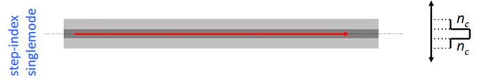
5 Single mode Step Index fiber The central region, the core, has greater refractive index than the outer region, the cladding. The fiber has cylindrical symmetry. We use the coordinates r, φ, z to represent any point in the fiber. Cladding is normally much thicker than shown. Department of Telecommunication, MUET UET Jamshoro 5

6 Single mode Step Index fiber Department of Telecommunication, MUET UET Jamshoro 6
7 Single mode Step Index fiber The optical fiber with a core of radius a and a constant refractive index n 1 and a cladding of slightly lower refractive index n 2 is known as step index fiber. n r = ቊ n 1 n 2 for r < a for r > a There are two basic types of single mode step-index fibers: matched clad (MC) and depressed clad (DC). Matched cladding means that the fiber cladding consists of a single homogeneous layer of dielectric material. Depressed cladding means that the fiber cladding consists of two regions: the inner and outer cladding regions. Department of Telecommunication, MUET UET Jamshoro 7
8 Single mode Step Index fiber Matched Cladding Core of radius a and RI n 1 Cladding of RI n2 where n 1 > n 2 Depressed Cladding Core of radius a and RI n 1 Inner cladding having RI n 2 where n 1 > n 2 Outer cladding having RI n 3 where n 1 > n 3 > n 2 Department of Telecommunication, MUET UET Jamshoro 8
9 SMF cutoff wavelength A wavelength above which a guided mode of a waveguide ceases to exist. So shorter the wavelength, greater number of modes can be guided through fiber. Single mode fiber cutoff wavelength is the smallest operating wavelength when single mode fibers propagate only the fundamental mode. At this wavelength, the 2nd-order mode becomes lossy and radiates out of the fiber core. As the operating wavelength becomes longer than the cutoff wavelength, the fundamental mode becomes increasingly lossy. Department of Telecommunication, MUET UET Jamshoro 9
10 SMF cutoff wavelength Department of Telecommunication, MUET UET Jamshoro 10
11 SMF cutoff wavelength Normalized propagation constant b vs. V-number for a step index fiber for various LP modes S.O. Kasap, Optoelectronics (Prentice Hall) Department of Telecommunication, MUET UET Jamshoro 11
12 Single Mode Step-index fiber A SM step-index fiber has low attenuation low intermodal dispersion (broadening of transmitted light pulse), as only one mode is transmitted, and high bandwidth properties. Present applications for single mode fibers include Long-haul, high-speed telecommunication systems. Future applications include single mode fibers for sensor systems. Department of Telecommunication, MUET UET Jamshoro 12
13 Multi-mode fiber Multimode (MM) Fiber: An optical fiber that has a core large enough to propagate more than one mode of light. The typical diameter is about 2.5 x 10⁻³ inches or 62.5 microns. Multimode Step-Index Fiber Fiber has a uniform index of refraction throughout the core that is a step below the index of refraction in the cladding Allows more than one mode of light. Department of Telecommunication, MUET UET Jamshoro 13
14 Multi-mode fiber Multimode Graded-Index Fiber A multimode graded-index fiber has a core of radius (a). Unlike step-index fibers, the value of the refractive index of the core (n1) varies according to the radial distance (r). The value of n1 decreases as the distance (r) from the center of the fiber increases. Department of Telecommunication, MUET UET Jamshoro 14

15 Multi-mode step-index fiber Multimode step index fibers allow the propagation of a finite number of guided modes along the channel. A multimode step-index fiber has a core of radius a and a constant refractive index n 1. A cladding of slightly lower refractive index n 2 surrounds the core. The difference in the core and cladding refractive index is the parameter Δ, given by: n n n1 Department of Telecommunication, MUET UET Jamshoro 15
16 Multi-mode step-index fiber In a typical MM step-index fiber, there are hundreds of propagating modes. Most modes in multimode step-index fibers propagate far from cut-off wavelength λ c. Modes away from the λ c concentrate most of their light energy into the fiber core. Since most modes propagate far from cutoff, the majority of light propagates in the fiber core. Modes close to λ c have a greater percentage of their light energy propagate in the cladding. Therefore, in multimode step-index fibers, cladding properties such as cladding diameter, have limited effect on mode (light) propagation. Department of Telecommunication, MUET UET Jamshoro 16
17 Multi-mode step-index fiber The total number of guided modes or mode volume Ms for a step index fiber is related to the normalized frequency, V, by the approximate expression: 2 V M s 2 This allows an estimate of the number of guided modes propagating in a particular multimode step index fiber. Only for large number of modes (V >> 2.4), the number of modes can be given by V 2 /2. Under this condition, the ratio between power travelling in the cladding and in the core is given by P cladding P total Department of Telecommunication, MUET UET Jamshoro M
18 Multi-mode step-index fiber Multimode step-index fibers have relatively large core diameters and large numerical apertures. A large core size and a large numerical aperture make it easier to couple light from LED into the fiber. Large number of modes possible Each mode travels at a different velocity Used in short links, mostly with LED sources Unfortunately, multimode step-index fibers have limited bandwidth capabilities. Dispersion, mainly modal dispersion, limits the bandwidth or information-carrying capacity of the fiber. Short-haul, limited bandwidth, low-cost applications typically use multimode step-index fibers. Department of Telecommunication, MUET UET Jamshoro 18
19 Multi-mode graded-index fiber Core refractive index gradually changes towards the cladding The light ray gradually bends and the TIR happens at different points The rays that travel longer distance also travel faster Offer less modal dispersion compared to Step Index MMF Department of Telecommunication, MUET UET Jamshoro 19
20 Multi-mode graded-index fiber In multimode (MM) graded-index fiber with core of radius a, unlike step-index fibers, the value of the refractive index of the core n1 varies according to the radial distance r i.e., such fibers do not have constant refractive index in the core. The value of n 1 decreases as the distance r from the center of the fiber increases. The index variation may be represented as: n r = n 1 1 r/a α 1 2 r < a core n = n 2 r a cladding where Δ is the relative refractive index difference and α is core radius. Department of Telecommunication, MUET UET Jamshoro 20
 A ray in thinly stratified medium becomes refracted as it passes from one layer to the next upper layer with lower n and eventually its angle satisfies TIR.")
21 TIR in multi-mode graded-index fiber n decreases step by step from one layer to next upper layer; very thin layers. Continuous decrease in n gives a ray path changing continuously. (a) A ray in thinly stratified medium becomes refracted as it passes from one layer to the next upper layer with lower n and eventually its angle satisfies TIR. (b) In a medium where n decreases continuously the path of the ray bends continuously. Department of Telecommunication, MUET UET Jamshoro 21
22 Multi-mode graded-index fiber Multimode graded-index fibers exhibit far less intermodal dispersion than multimode step index fivers due to their refractive index profile. This results in the transmission bandwidths which may be orders of magnitude greater than multimode step index fiber bandwidths. Department of Telecommunication, MUET UET Jamshoro 22
23 Multi-mode graded-index fiber The total number of guided modes or mode volume Mg for a graded-index fiber is related to the normalized frequency, V, by the approximate expression: M g 2 V 2 2 Hence, for a parabolic refractive index profile core (α= 2), 2 V M g 4 Department of Telecommunication, MUET UET Jamshoro 23
24 Multi-mode graded-index fiber Step-index Multimode fiber Graded-indexed Multimode fiber Step-indexed Single mode fiber Department of Telecommunication, MUET UET Jamshoro 24
25 Typical dimensions Department of Telecommunication, MUET UET Jamshoro 25

26 Applications of Optical Fiber Department of Telecommunication, MUET UET Jamshoro 26
27 Applications of Optical Fiber Applications Most present day applications involving multimode fiber use graded-index fibers. LAN Advantages In most applications, a multimode graded-index fiber with a core and cladding size of 62.5/125 μm offers the best combination of the following properties: Relatively high source-to-fiber coupling efficiency Low loss Department of Telecommunication, MUET UET Jamshoro 27
28 Applications of Optical Fiber Low sensitivity to microbending and macrobending High bandwidth Expansion capability Disadvantages In LAN type environment, macrobends and microbands losses are hard to predict. Cable tension, bends, and local tie-downs increase macrobend and microbend losses. Department of Telecommunication, MUET UET Jamshoro 28
29 Summary Department of Telecommunication, MUET UET Jamshoro 29
Guided Propagation Along the Optical Fiber. Xavier Fernando Ryerson Comm. Lab
 Guided Propagation Along the Optical Fiber Xavier Fernando Ryerson Comm. Lab The Nature of Light Quantum Theory Light consists of small particles (photons) Wave Theory Light travels as a transverse electromagnetic
Lecture 10. Dielectric Waveguides and Optical Fibers
 Lecture 10 Dielectric Waveguides and Optical Fibers Slab Waveguide, Modes, V-Number Modal, Material, and Waveguide Dispersions Step-Index Fiber, Multimode and Single Mode Fibers Numerical Aperture, Coupling
Guided Propagation Along the Optical Fiber. Xavier Fernando Ryerson University
 Guided Propagation Along the Optical Fiber Xavier Fernando Ryerson University The Nature of Light Quantum Theory Light consists of small particles (photons) Wave Theory Light travels as a transverse electromagnetic
Guided Propagation Along the Optical Fiber
 Guided Propagation Along the Optical Fiber The Nature of Light Quantum Theory Light consists of small particles (photons) Wave Theory Light travels as a transverse electromagnetic wave Ray Theory Light
Waveguides and Optical Fibers
 Waveguides and Optical Fibers Dielectric Waveguides Light Light Light n n Light n > n A planar dielectric waveguide has a central rectangular region of higher refractive index n than the surrounding region
Lectureo5 FIBRE OPTICS. Unit-03
 Lectureo5 FIBRE OPTICS Unit-03 INTRODUCTION FUNDAMENTAL IDEAS ABOUT OPTICAL FIBRE Multimode Fibres Multimode Step Index Fibres Multimode Graded Index Fibres INTRODUCTION In communication systems, there
Fiber Optic Communication Systems. Unit-04: Theory of Light. https://sites.google.com/a/faculty.muet.edu.pk/abdullatif
 Unit-04: Theory of Light https://sites.google.com/a/faculty.muet.edu.pk/abdullatif Department of Telecommunication, MUET UET Jamshoro 1 Limitations of Ray theory Ray theory describes only the direction
Fiber Optic Communications Communication Systems
 INTRODUCTION TO FIBER-OPTIC COMMUNICATIONS A fiber-optic system is similar to the copper wire system in many respects. The difference is that fiber-optics use light pulses to transmit information down
1. Evolution Of Fiber Optic Systems
 OPTICAL FIBER COMMUNICATION UNIT-I : OPTICAL FIBERS STRUCTURE: 1. Evolution Of Fiber Optic Systems The operating range of optical fiber system term and the characteristics of the four key components of
UNIT-II : SIGNAL DEGRADATION IN OPTICAL FIBERS
 UNIT-II : SIGNAL DEGRADATION IN OPTICAL FIBERS The Signal Transmitting through the fiber is degraded by two mechanisms. i) Attenuation ii) Dispersion Both are important to determine the transmission characteristics
2. The Basic principle of optical fibre (Or) Working principle of optical fibre (or) Total internal reflection
 Working principle of optical fibre (or) Total internal reflection") Introduction Fibre optics deals with the light propagation through thin glass fibres. Fibre optics plays an important role in the field of communication to transmit voice, television and digital data signals
Introduction Fibre optics deals with the light propagation through thin glass fibres. Fibre optics plays an important role in the field of communication to transmit voice, television and digital data signals
FIBER OPTICS. Prof. R.K. Shevgaonkar. Department of Electrical Engineering. Indian Institute of Technology, Bombay. Lecture: 4
 FIBER OPTICS Prof. R.K. Shevgaonkar Department of Electrical Engineering Indian Institute of Technology, Bombay Lecture: 4 Modal Propagation of Light in an Optical Fiber Fiber Optics, Prof. R.K. Shevgaonkar,
DIELECTRIC WAVEGUIDES and OPTICAL FIBERS
 DIELECTRIC WAVEGUIDES and OPTICAL FIBERS Light Light Light n 2 n 2 Light n 1 > n 2 A planar dielectric waveguide has a central rectangular region of higher refractive index n 1 than the surrounding region
Design of a double clad optical fiber with particular consideration of leakage losses
 Vol. (4), pp. 7-62 October, 23 DOI.897/JEEER23.467 ISSN 993 822 23 Academic Journals http://www.academicjournals.org/jeeer Journal of Electrical and Electronics Engineering Research Full Length Research
Fiber Optics Dr. Vipul Rastogi Department of Physics Indian Institute of Technology, Roorkee. Lecture - 04 Salient features of optical fiber II
 Fiber Optics Dr. Vipul Rastogi Department of Physics Indian Institute of Technology, Roorkee Lecture - 04 Salient features of optical fiber II In the last lecture we had understood the propagation characteristics
SIGNAL DEGRADATION IN OPTICAL FIBERS
 Volume Issue January 04, ISSN 348 8050 SIGNAL DEGRADATION IN OPTICAL FIBERS Gyan Prakash Pal, Manishankar Gupta,,, Assistant Professor, Electronics & Communication Engineering Department, Shanti Institute
The absorption of the light may be intrinsic or extrinsic
 Attenuation Fiber Attenuation Types 1- Material Absorption losses 2- Intrinsic Absorption 3- Extrinsic Absorption 4- Scattering losses (Linear and nonlinear) 5- Bending Losses (Micro & Macro) Material
FIBER OPTICS. Dr D. Arun Kumar Assistant Professor Department of Physical Sciences Bannari Amman Institute of Technology Sathyamangalam
 FIBER OPTICS Dr D. Arun Kumar Assistant Professor Department of Physical Sciences Bannari Amman Institute of Technology Sathyamangalam General Objective To understand the propagation of light through optical
is a method of transmitting information from one place to another by sending light through an optical fiber. The light forms an electromagnetic
 is a method of transmitting information from one place to another by sending light through an optical fiber. The light forms an electromagnetic carrier wave that is modulated to carry information. The
Optical Fiber Technology. Photonic Network By Dr. M H Zaidi
 Optical Fiber Technology Numerical Aperture (NA) What is numerical aperture (NA)? Numerical aperture is the measure of the light gathering ability of optical fiber The higher the NA, the larger the core
Optical Fiber Communication
 A Seminar report On Optical Fiber Communication Submitted in partial fulfillment of the requirement for the award of degree Of Mechanical SUBMITTED TO: www.studymafia.org SUBMITTED BY: www.studymafia.org
Chapter 3 Signal Degradation in Optical Fibers
 What about the loss in optical fiber? Why and to what degree do optical signals gets distorted as they propagate along a fiber? Fiber links are limited by in path length by attenuation and pulse distortion.
Fiber Optic Principles. Oct-09 1
 Fiber Optic Principles Oct-09 1 Fiber Optic Basics Optical fiber Active components Attenuation Power budget Bandwidth Oct-09 2 Reference www.flukenetworks.com/fiber Handbook Fiber Optic Technologies (Vivec
Photonics and Optical Communication
 Photonics and Optical Communication (Course Number 300352) Spring 2007 Dr. Dietmar Knipp Assistant Professor of Electrical Engineering http://www.faculty.iu-bremen.de/dknipp/ 1 Photonics and Optical Communication
Class 4 ((Communication and Computer Networks))
)") Class 4 ((Communication and Computer Networks)) Lesson 3... Transmission Media, Part 1 Abstract The successful transmission of data depends principally on two factors: the quality of the signal being transmitted
Class 4 ((Communication and Computer Networks)) Lesson 3... Transmission Media, Part 1 Abstract The successful transmission of data depends principally on two factors: the quality of the signal being transmitted
Study of Optical Fiber Design Parameters in Fiber Optics Communications
 Kurdistan Journal of Applied Research (KJAR) Print-ISSN: 2411-7684 Electronic-ISSN: 2411-7706 kjar.spu.edu.iq Volume 2 Issue 3 August 2017 DOI: 10.24017/science.2017.3.52 Study of Optical Fiber Design
UNIT Write notes on broadening of pulse in the fiber dispersion?
 UNIT 3 1. Write notes on broadening of pulse in the fiber dispersion? Ans: The dispersion of the transmitted optical signal causes distortion for both digital and analog transmission along optical fibers.
Multimode Optical Fiber
 Multimode Optical Fiber 1 OBJECTIVE Determine the optical modes that exist for multimode step index fibers and investigate their performance on optical systems. 2 PRE-LAB The backbone of optical systems
Geometrical Optics Fiber optics The eye
 Phys 322 Lecture 16 Chapter 5 Geometrical Optics Fiber optics The eye First optical communication Alexander Graham Bell 1847-1922 1880: photophone 4 years after inventing a telephone! Fiberoptics: first
τ mod = T modal = longest ray path shortest ray path n 1 L 1 = L n 2 1
 S. Blair February 15, 2012 23 2.2. Pulse dispersion Pulse dispersion is the spreading of a pulse as it propagates down an optical fiber. Pulse spreading is an obvious detrimental effect that limits the
Section B Lecture 5 FIBER CHARACTERISTICS
 Section B Lecture 5 FIBER CHARACTERISTICS Material absorption Losses Material absorption is a loss mechanism related to material composition and fabrication process for the fiber. This results in dissipation
NEW YORK CITY COLLEGE of TECHNOLOGY
 NEW YORK CITY COLLEGE of TECHNOLOGY THE CITY UNIVERSITY OF NEW YORK DEPARTMENT OF ELECTRICAL AND TELECOMMUNICATIONS ENGINEERING TECHNOLOGY Course : Prepared by: TCET 4102 Fiber-optic communications Module
COM 46: ADVANCED COMMUNICATIONS jfm 07 FIBER OPTICS
 FIBER OPTICS Fiber optics is a unique transmission medium. It has some unique advantages over conventional communication media, such as copper wire, microwave or coaxial cables. The major advantage is
Chapter 18: Fiber Optic and Laser Technology
 Chapter 18: Fiber Optic and Laser Technology Chapter 18 Objectives At the conclusion of this chapter, the reader will be able to: Describe the construction of fiber optic cable. Describe the propagation
LECTURE NOTES OPTICAL FIBER COMMUNICATION (15A04701) IV B. Tech I Semester (JNTUA-R15) Mrs. N.Pranavi, Assistant Professor
 IV B. Tech I Semester (JNTUA-R15) Mrs. N.Pranavi, Assistant Professor") LECTURE NOTES ON OPTICAL FIBER COMMUNICATION (15A04701) 2018 2019 IV B. Tech I Semester (JNTUA-R15) Mrs. N.Pranavi, Assistant Professor CHADALAWADA RAMANAMMA ENGINEERING COLLEGE (AUTONOMOUS) Chadalawada
LECTURE NOTES ON OPTICAL FIBER COMMUNICATION (15A04701) 2018 2019 IV B. Tech I Semester (JNTUA-R15) Mrs. N.Pranavi, Assistant Professor CHADALAWADA RAMANAMMA ENGINEERING COLLEGE (AUTONOMOUS) Chadalawada
Optical fibre. Principle and applications
 Optical fibre Principle and applications Circa 2500 B.C. Earliest known glass Roman times-glass drawn into fibers Venice Decorative Flowers made of glass fibers 1609-Galileo uses optical telescope 1626-Snell
SKP Engineering College
 SKP Engineering College Tiruvannamalai 606611 A Course Material on Optical Communication and Networks By M.Mageshbabu Assistant Professor Electronics and Communication Engineering Department Electronics
Fiber Optics IV - Testing
 PDHonline Course E311 (3 PDH) Fiber Optics IV - Testing Instructor: Lee Layton, PE 2012 PDH Online PDH Center 5272 Meadow Estates Drive Fairfax, VA 22030-6658 Phone & Fax: 703-988-0088 www.pdhonline.org
SYLLABUS. Optical Fiber Communication
 SYLLABUS Optical Fiber Communication Subject Code : IA Marks : 25 No. of Lecture Hrs/Week : 04 Exam Hours : 03 Total no. of Lecture Hrs. : 52 Exam Marks : 100 UNIT - 1 PART - A OVERVIEW OF OPTICAL FIBER
Intensity Modulation. Wei-Chih Wang Department of Mechanical Engineering University of Washington. W. Wang
 Intensity Modulation Wei-Chih Wang Department of Mechanical Engineering University of Washington Why Intensity Modulation Simple optical setup Broadband or mono-chormatic light source Less sensitive but
Study of Circular Bends in Multimode Polymer Optical Fiber Couplers Fabrication Using Lapping Technique
 Study of Circular Bends in Multimode Polymer Optical Fiber Couplers Fabrication Using Lapping Technique L.S.Supian* 1,2, Mohd Syuhaimi Ab-Rahman 1, Norhana Arsad 1, Harry Ramza 1 1 Department of Electrical,
Chromatic Dispersion Compensation in Optical Fiber Communication System and its Simulation
 Indian Journal of Science and Technology Supplementary Article Chromatic Dispersion Compensation in Optical Fiber Communication System and its Simulation R. Udayakumar 1 *, V. Khanaa 2 and T. Saravanan
WHITE PAPER LINK LOSS BUDGET ANALYSIS TAP APPLICATION NOTE LINK LOSS BUDGET ANALYSIS
 TAP APPLICATION NOTE LINK LOSS BUDGET ANALYSIS WHITE PAPER JULY 2017 1 Table of Contents Basic Information... 3 Link Loss Budget Analysis... 3 Singlemode vs. Multimode... 3 Dispersion vs. Attenuation...
Industrial Instrumentation Prof. A. Barua Department of Electrical Engineering Indian Institute of Technology, Kharagpur
 Industrial Instrumentation Prof. A. Barua Department of Electrical Engineering Indian Institute of Technology, Kharagpur Lecture - 29 Optoelectronic Sensor-II (Refer Slide Time: 00:36) Welcome to lesson
Optical Fiber. n 2. n 1. θ 2. θ 1. Critical Angle According to Snell s Law
 ECE 271 Week 10 Critical Angle According to Snell s Law n 1 sin θ 1 = n 1 sin θ 2 θ 1 and θ 2 are angle of incidences The angle of incidence is measured with respect to the normal at the refractive boundary
Nufern 980 nm Select Cut-Off Single-Mode Fiber
 Nufern 980 nm Select Cut-Off Single-Mode Fiber Nufern s 980 nm high-performance select cut-off single-mode fibers are optimized for use by component manufacturers in the telecommunications wavelengths.
Industrial Automation
 OPTICAL FIBER. SINGLEMODE OR MULTIMODE It is important to understand the differences between singlemode and multimode fiber optics before selecting one or the other at the start of a project. Its different
FiberHome Fiber Products
 FiberHome Fiber Products FiberHome OPTICAL FIBER ISO 9001specification Shanghai stock code:600498 Fiber Products FiberHome Low Water Peak Single mode Fiber FiberHome Bending Insensitive Single mode Fiber
SPECIFICATION. FOR SINGLE-MODE OPTICAL FIBER (FutureGuide -SR15E)
") Fujikura DATE Aug. 18, 2008 NO. JFS-00052A Supersedes JFS-00052 Messrs. SPECIFICATION FOR SINGLE-MODE OPTICAL FIBER (FutureGuide -SR15E) Prepared by H. KIKUCHI Manager Optical Fiber and Cable Dept. Global
Fujikura DATE Aug. 18, 2008 NO. JFS-00052A Supersedes JFS-00052 Messrs. SPECIFICATION FOR SINGLE-MODE OPTICAL FIBER (FutureGuide -SR15E) Prepared by H. KIKUCHI Manager Optical Fiber and Cable Dept. Global
Optical systems have carrier frequencies of ~100 THz. This corresponds to wavelengths from µm.
 Introduction A communication system transmits information form one place to another. This could be from one building to another or across the ocean(s). Many systems use an EM carrier wave to transmit information.
Total care for networks. Introduction to Dispersion
 Introduction to Dispersion Introduction to PMD Version1.0- June 01, 2000 Copyright GN Nettest 2000 Introduction To Dispersion Contents Definition of Dispersion Chromatic Dispersion Polarization Mode Dispersion
Differential Mode Group Delay (DMGD) in Few Mode Fibers (FMF)
 in Few Mode Fibers (FMF)") Differential Mode Group Delay (DMGD) in Few Mode Fibers (FMF) Microwave Interferometric Technique for Characterizing Few Mode Fibers Abstract We propose and experimentally demonstrate a simple and accurate
Differential Mode Group Delay (DMGD) in Few Mode Fibers (FMF) Microwave Interferometric Technique for Characterizing Few Mode Fibers Abstract We propose and experimentally demonstrate a simple and accurate
Comparison of FRD (Focal Ratio Degradation) for Optical Fibres with Different Core Sizes By Neil Barrie
 for Optical Fibres with Different Core Sizes By Neil Barrie") Comparison of FRD (Focal Ratio Degradation) for Optical Fibres with Different Core Sizes By Neil Barrie Introduction The purpose of this experimental investigation was to determine whether there is a dependence
Comparison of FRD (Focal Ratio Degradation) for Optical Fibres with Different Core Sizes By Neil Barrie Introduction The purpose of this experimental investigation was to determine whether there is a dependence
Splice losses in holey optical fibers
 Splice losses in holey optical fibers J.T. Lizier and G.E. Town School of Electrical and Information Engineering (J03), University of Sydney, NSW 2006, Australia. Tel: +612-9351-2110, Fax: +612-9351-3847,
Chapter 2: Fiber Optics as a communication medium
 Chapter 2: Fiber Optics as a communication medium 2.1 Fiber Fabrication: Basically, fiber manufacturers use two methods to fabricate multimode and single mode glass fibers. One method is vapor phase oxidation,
Why Using Fiber for transmission
 Why Using Fiber for transmission Why Using Fiber for transmission Optical fibers are widely used in fiber-optic communications, where they permit transmission over long distances and at very high bandwidths.
TOPIC 2 WAVEGUIDE AND COMPONENTS
 TOPIC 2 WAVEGUIDE AND COMPONENTS COURSE LEARNING OUTCOME (CLO) CLO1 Explain clearly the generation of microwave, the effects of microwave radiation and the propagation of electromagnetic in a waveguide
Laboratory of Optoelectornics
 Department of Semiconductor of Optoelectronics Devices Laboratory of Optoelectornics Instruction 3 Measurement of the influence of fibers optisc macrobending on their attenuation. 1. Goal In this exercise
2 in the multipath dispersion of the optical fibre. (b) Discuss the merits and drawbacks of cut bouls method of measurement of alternation.
 Discuss the merits and drawbacks of cut bouls method of measurement of alternation.") B.TECH IV Year I Semester (R09) Regular Examinations, November 2012 1 (a) Derive an expression for multiple time difference tt 2 in the multipath dispersion of the optical fibre. (b) Discuss the merits
B.TECH IV Year I Semester (R09) Regular Examinations, November 2012 1 (a) Derive an expression for multiple time difference tt 2 in the multipath dispersion of the optical fibre. (b) Discuss the merits
Books: 1. Data communications by William L Schweber 2. Data communication and Networking by Behrouz A F0rouzan
 Books: 1. Data communications by William L Schweber 2. Data communication and Networking by Behrouz A F0rouzan Twisted Pair cable Multiconductor flat cable Advantages of Twisted Pair Cable Simplest to
Fiberoptic and Waveguide Sensors
 Fiberoptic and Waveguide Sensors Wei-Chih Wang Department of Mecahnical Engineering University of Washington Optical sensors Advantages: -immune from electromagnetic field interference (EMI) - extreme
Fiber Optic Communication Link Design
 Fiber Optic Communication Link Design By Michael J. Fujita, S.K. Ramesh, PhD, Russell L. Tatro Abstract The fundamental building blocks of an optical fiber transmission link are the optical source, the
Optical behavior. Reading assignment. Topic 10
 Reading assignment Optical behavior Topic 10 Askeland and Phule, The Science and Engineering of Materials, 4 th Ed.,Ch. 0. Shackelford, Materials Science for Engineers, 6 th Ed., Ch. 16. Chung, Composite
OptoLup TM POF cable Data Sheet. Overview. COMOSS OptoLup TM Cable is a type of APF, All. for the transmitting. compliant POF cables.
 IEEE 1394b Series Dongle OptoLup TM OptoLup TM Data Sheet Ver. 1.0 Overview COMOSS OptoLup TM Cable is a type of APF, All Plastic-fiber; both the core and the cladding are made of plastic, among of which
Examination Optoelectronic Communication Technology. April 11, Name: Student ID number: OCT1 1: OCT 2: OCT 3: OCT 4: Total: Grade:
 Examination Optoelectronic Communication Technology April, 26 Name: Student ID number: OCT : OCT 2: OCT 3: OCT 4: Total: Grade: Declaration of Consent I hereby agree to have my exam results published on
Physical Layer Cabling: Fiber-Optic
 Physical Layer Cabling: Fiber-Optic Fiber-Optic Basics The EM Spectrum: Physics and Math Attenuation and Dispersion in Fiber Fiber-Optic Hardware Networking over Fiber-Optic Safety with Fiber Fiber-Optic
OPTICAL FIBER COMMUNICATION
 OPTICAL FIBER COMMUNICATION Subject Code: IA Marks: 25 No. of Lecture Hrs/Week: 04 Exam Hours: 03 Total no. of Lecture Hrs. 52 Exam Marks: 100 PART - A UNIT - 1 OVERVIEW OF OPTICAL FIBER COMMUNICATION:
Data and Computer Communications Chapter 4 Transmission Media
 Data and Computer Communications Chapter 4 Transmission Media Ninth Edition by William Stallings Data and Computer Communications, Ninth Edition by William Stallings, (c) Pearson Education - Prentice Hall,
Department of Electrical Engineering and Computer Science
 MASSACHUSETTS INSTITUTE of TECHNOLOGY Department of Electrical Engineering and Computer Science 6.161/6637 Practice Quiz 2 Issued X:XXpm 4/XX/2004 Spring Term, 2004 Due X:XX+1:30pm 4/XX/2004 Please utilize
Concepts of optical signal processing and optical communications
 Concepts of optical signal processing and optical communications Electronic components allowing to control electric currents with electric currents (or voltages) and integration of a large number of such
Chapter 2: Computer Networks
 Chapter 2: Computer Networks 2.1: Physical Layer: representation of digital signals 2.2: Data Link Layer: error protection and access control 2.3: Network infrastructure 2.4 2.5: Local Area Network examples
TECHNICAL ARTICLE: DESIGN BRIEF FOR INDUSTRIAL FIBRE OPTICAL NETWORKS
 TECHNICAL ARTICLE: DESIGN BRIEF FOR INDUSTRIAL FIBRE OPTICAL NETWORKS Designing and implementing a fibre optical based communication network intended to replace or augment an existing communication network
Absorption: in an OF, the loss of Optical power, resulting from conversion of that power into heat.
 Absorption: in an OF, the loss of Optical power, resulting from conversion of that power into heat. Scattering: The changes in direction of light confined within an OF, occurring due to imperfection in
Introduction to Fiber Optics
 Introduction to Fiber Optics Dr. Anurag Srivastava Atal Bihari Vajpayee Indian Institute of Information Technology and Manegement, Gwalior Milestones in Electrical Communication 1838 Samuel F.B. Morse
EKT 465 OPTICAL COMMUNICATION SYSTEM. Chapter 2 OPTICAL FIBER COMMUNICATIONS
 EKT 465 OPTICAL COMMUNICATION SYSTEM Chapter 2 OPTICAL FIBER COMMUNICATIONS SEMESTER 1-2017/18 3 Credit Hours 222.3 Gbps pada 2017, daripada 6.4Gbps pada 2012 10/3/2017 2 Light Propagation & Transmission
UNIT I INTRODUCTION TO OPTICAL FIBERS
 UNIT I INTRODUCTION TO OPTICAL FIBERS 9 Evolution of fiber optic system Element of an Optical Fiber Transmission link Total internal reflection Acceptance angle Numerical aperture Skew rays Ray Optics
Photograph of the rectangular waveguide components
 Waveguides Photograph of the rectangular waveguide components BACKGROUND A transmission line can be used to guide EM energy from one point (generator) to another (load). A transmission line can support
Optical Amplifiers Photonics and Integrated Optics (ELEC-E3240) Zhipei Sun Photonics Group Department of Micro- and Nanosciences Aalto University
 Zhipei Sun Photonics Group Department of Micro- and Nanosciences Aalto University") Photonics Group Department of Micro- and Nanosciences Aalto University Optical Amplifiers Photonics and Integrated Optics (ELEC-E3240) Zhipei Sun Last Lecture Topics Course introduction Ray optics & optical
Photonics Group Department of Micro- and Nanosciences Aalto University Optical Amplifiers Photonics and Integrated Optics (ELEC-E3240) Zhipei Sun Last Lecture Topics Course introduction Ray optics & optical
The electric field for the wave sketched in Fig. 3-1 can be written as
 ELECTROMAGNETIC WAVES Light consists of an electric field and a magnetic field that oscillate at very high rates, of the order of 10 14 Hz. These fields travel in wavelike fashion at very high speeds.
Teaching fiber-optic communications in engineering technology programs by virtual collaboration with industry
 Teaching fiber-optic communications in engineering technology programs by virtual collaboration with industry Djafar K. Mynbaev New York City College of Technology of the City University of New York, 300
Effective Cutoff Wavelength Measurement of Bend-insensitive Fiber by Longitudinal Misalignment Loss Method. Won-Taek Han
 Advanced Materials Research Vols. 123-125 (2010) pp 419-422 Online available since 2010/Aug/11 at www.scientific.net (2010) Trans Tech Publications, Switzerland doi:10.4028/www.scientific.net/amr.123-125.419
Comparative Study of an Optical Link with PIN and APD as Photo-Detector Preetam Jain 1, Dr Lochan Jolly 2
 Comparative Study of an Optical Link with PIN and APD as Photo-Detector Preetam Jain 1, Dr Lochan Jolly 2 1 ME EXTC Student Thakur College of Engineering and Technology 2 Professor Thakur College of Engineering
ENDLESS INNOVATION OPTICAL FIBER. Bendfree Bendfree+ UltraPass. WidePass. Ultra Bendfree
 ENDLESS INNOVATION Today, vast amounts of information are running across the transmission at extremely high speeds. OPTICAL FIBER Samsung offers a full line of optical fibers for all network applications,
Attenuation and Time Dispersion Measurements of Graded Index Polymer Optical Fiber for. Indoor Cellular Coverage
 Contemporary Engineering Sciences, Vol. 2, 2009, no. 2, 47-58 Attenuation and Time Dispersion Measurements of Graded Index Polymer Optical Fiber for Indoor Cellular Coverage S. Louvros and I. E. Kougias
Application Note 5596
 Polymer Optical Fiber (POF) Application Note 5596 Table of Contents Part 1. POF Overview 1 Introduction 2 Principle of operation 2 Numerical Aperture 2 Modes 3 Attenuation 4 Rayleigh scattering 4 Absorption
EC LIGHT WAVE COMMUNICATION. To know principle of light wave communication and the characteristics of optical devices.
 EC010 803 LIGHT WAVE COMMUNICATION Objectives To understand the behavior of light wave To know principle of light wave communication and the characteristics of optical devices. Module 1 (12hrs) : Recollection
Types of losses in optical fiber cable are: Due to attenuation, the power of light wave decreases exponentially with distance.
 UNIT-II TRANSMISSION CHARACTERISTICS OF OPTICAL FIBERS SIGNAL ATTENUATION: Signal attenuation in an optical fiber is defined as the decrease in light power during light propagation along an optical fiber.
Power Communication using Optical-fiber
 Power Communication using Optical-fiber Saurabh 1 Varun Kumar 2 1 Modinagar, Ghaziabad 2 Room N0.314 Ginni Hostel, KNGD Campus Modinagar, Ghaziabad ABSTRACT Power transmission is a very important tool
Volume 2, Issue 11, November 2014 ISSN
 Experimental Investigation of Bending Loss in Multimode optical fiber used for the Delivery of Optical Power From Sources at 650nm and 532nm Wavelength Samar Y. Al Dabagh 1 and Duaa H. Al Saud 1 1 Department
Spiral Launch Method for Enhanced MMF Bandwidth
 Spiral Launch Method for Enhanced MMF Bandwidth D. Vernooy and H. Blauvelt Xponent Photonics March 2004 IEEE 802.2 10Gb/s on FDDI-grade MM fiber Study Group hblauvelt@xponentinc.com 1 Outline I. Overview
INTERNATIONAL TELECOMMUNICATION UNION TRANSMISSION MEDIA CHARACTERISTICS CHARACTERISTICS OF A DISPERSION-SHIFTED SINGLE-MODE OPTICAL FIBRE CABLE
 INTERNATIONAL TELECOMMUNICATION UNION ITU-T G.653 TELECOMMUNICATION (03/93) STANDARDIZATION SECTOR OF ITU TRANSMISSION MEDIA CHARACTERISTICS CHARACTERISTICS OF A DISPERSION-SHIFTED SINGLE-MODE OPTICAL
How Bend Insensitive Multimode Fiber is Affecting Installation and Testing of Enterprise and Data Center Cabling
 How Bend Insensitive Multimode Fiber is Affecting Installation and Testing of Enterprise and Data Center Cabling David Mazzarese, Technical Manager, Fiber Systems and Standards Engineering, OFS Learning
Data and Computer Communications. Tenth Edition by William Stallings
 Data and Computer Communications Tenth Edition by William Stallings Data and Computer Communications, Tenth Edition by William Stallings, (c) Pearson Education - Prentice Hall, 2013 Wireless Transmission
Chapter 9 GUIDED WAVE OPTICS
 [Reading Assignment, Hecht 5.6] Chapter 9 GUIDED WAVE OPTICS Optical fibers The step index circular waveguide is the most common fiber design for optical communications plastic coating (sheath) core cladding
Multimode fiber media types for 802.3cd
 1 Multimode fiber media types for 802.3cd P802.3cd, Fort Worth, Texas September 12-16, 2016 Rick Pimpinella Jose Castro Brett Lane Panduit Labs, Panduit Corp. 2 Laser Optimized Multimode Fiber Types Fiber
MAHALAKSHMI ENGINEERING COLLEGE TIRUCHIRAPALLI
 MAHALAKSHMI ENGINEERING COLLEGE TIRUCHIRAPALLI - 621213 DEPARTMENT : ECE SUBJECT NAME : OPTICAL COMMUNICATION & NETWORKS SUBJECT CODE : EC 2402 UNIT II: TRANSMISSION CHARACTERISTICS OF OPTICAL FIBERS PART
OPTICAL NETWORKS. Building Blocks. A. Gençata İTÜ, Dept. Computer Engineering 2005
 OPTICAL NETWORKS Building Blocks A. Gençata İTÜ, Dept. Computer Engineering 2005 Introduction An introduction to WDM devices. optical fiber optical couplers optical receivers optical filters optical amplifiers
SSRG International Journal of Electronics and Communication Engineering (SSRG-IJECE) Volume 2 Issue 6 June 2015
 Volume 2 Issue 6 June 2015") SSRG International Journal of Electronics and Communication Engineering (SSRG-IJECE) Volume Issue 6 June 15 Designing of a Long Period Fiber Grating (LPFG) using Optigrating Simulation Software Mr. Puneet
SSRG International Journal of Electronics and Communication Engineering (SSRG-IJECE) Volume Issue 6 June 15 Designing of a Long Period Fiber Grating (LPFG) using Optigrating Simulation Software Mr. Puneet
APPLICATION NOTE
 THE PHYSICS BEHIND TAG OPTICS TECHNOLOGY AND THE MECHANISM OF ACTION OF APPLICATION NOTE 12-001 USING SOUND TO SHAPE LIGHT Page 1 of 6 Tutorial on How the TAG Lens Works This brief tutorial explains the
Variation in Multimode Fiber Response: Summary of Experimental Results
 Summary of Experimental Results IEEE P802.3aq 10GBASE-LRM, Task Group 4 November, 2004, San Antonio Infineon Fiber Optics, Infineon Fiber Optics Page 1 Summary of Experimental Results! Introduction A variation