RÀi o. Ill.i:1: T It11Af1: [MOM I[A[=T. formerly. TELEVISION TECHNiQUE SPEEDS UP FACSIMILE. Editor HUGO GERNSRACN, SEE TELEVISION SECTION
|
|
|
- Joy Bradford
- 5 years ago
- Views:
Transcription


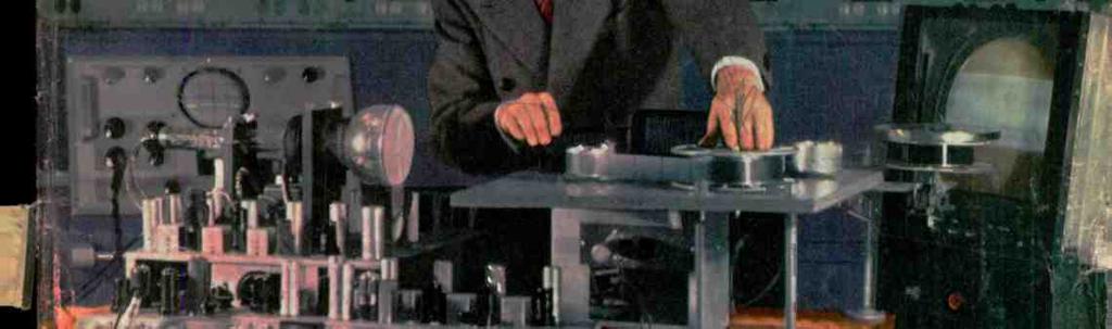


1 RÀi o Ill.i:1: T It11Af1: HUGO GERNSRACN, Editor formerly [MOM I[A[=T TELEVISION TECHNiQUE SPEEDS UP FACSIMILE SEE TELEVISION SECTION


 DUMONT INPUTUNER all channels - All FM Radio MODEL P -520 RCA 12\" HIGH FIDELITY PM SPEAKER MANUAL OF INSTRUCTIONS")


 completely wired, tubed, tested and aligned.")
2 TELEVIS0 AMR u Ell for the best in TELEVISION for CUSTOM-BUILT installations PROJECTION TELEVISION Bausch & Lomb Optical Electronic System provides a contrasty sparkling picture projected onto the Eastman Kodak Glass Projection Screen, completely glare -proof. Every part of the entire set is designed, engineered and manufactured for the express purpose of bringing you the finest in television.. - ready for CUSTOM -BUILT installations in homes, schools, lodges, clubs, hospitals, taverns and other public places. BAUSCH & LOMB F11.9 PROJECTION LENS RCA 5TP4 PROJECTION C. R. TUBE PRE -WIRED KV TRIPLER FLYBACK 10" 12" or 15" TUBE TELEVISION in easy to install units POWER SUPPLY ALUMINUM COATED TOP PROJECTION MIRROR EASTMAN KODAK GLASS PROJECTION SCREEN PRE -WIRED, PRE -TUNED I. F. PICTURE 8 SOUND STRIP (PAT. PEND.) DUMONT INPUTUNER all channels - All FM Radio MODEL P -520 RCA 12" HIGH FIDELITY PM SPEAKER MANUAL OF INSTRUCTIONS 8 SCHEMATIC DATA prepared 8 edited by renowned JOHN F. RIDER PUBLISHER, INC. COMPLETE WITH RACK, HOOD 8 PICTURE FRAME Here's why Television Experts praise T.A.C. Television Our products contain every new development, every new creation of television research. Our efforts are bent towards quality and this is particularly evident in the performance of our Assemblies. That's why men who know television are telling others about T.A.C. supremacy. il TELEVISION ASSEMBLY COMPANY GUARANTEE All components are of the finest quality and are fully guaran teed under the Standard RMA Guarantee. All TAC Assemblies are guaranteed to operate when assembled according to L directions., STANDARD MODELS 30- tubes, including the C.R. Tube. Supplied with 13 -tube I.F. Picture and Sound Strip (Pat. Pend.) completely wired, tubed, tested and aligned. Has standard tuner pre -wired to handle 13 channels, ready to use with above unit. T. A. C. CHAMPION MODELS WITH DUMONT INPUTUNER Gives continuous tuning for all 13 channels plus oll FM Radio. Assailable for all tube sizes. G-Q LEV SIN ASSEE Y E li Available only through National Parts Distributors Write us for list Write for literature 540 Bushwick Ave., B'klyn 6, N. Y. Smart, Modern Hand -Robbed Walnut 8 Blonde Cabinets for 10" 11'' or 15" tube chassis Our own exclusive designs, avail_ able for all T.A.0 models. Details on request t


3 3 LEARN RADIO srpracticino _i part of my Course I send transformer you the speaker, loop tubes, antenna, etc., to build Radio Receiver! this modern, In addition, powerful I send you r. y' other real Radio parts circuits, to build like the Signal many '- _: and Superheterodyne Generator, Receiver Radio pictured Tester below. You use this Z4 cr IN SPARE 7/MEAs =LS ` \ material to get practical Radio experience and to make EXTRA money fixing neighbors' Radios in spare time. Mail coupon below for complete information t I SEND YOU BIG KITS OF PARTS You Build and Experiment J. g. amitn, Prealdant Ilatlonal Radio Inalltuta I TRAINED THESE MEN Silts jn I Stet lia Nast "I am Radio Serviceman for The Adams Appliance Co. Am now get -, ting 960 a week, plus bonus and over - time."-w. A. ANGEL. Blytheeville Arkansas. ht, g stet! radis "I knew nothi n g about Radio when I enrolled. I am doing spare time work. I have more than paid for my Course and about 9200 worth of equip- ment." - RAYMOND HOLTCAMP, Vandalia, Illinois. With this MODERN RADIO AND MANY OTHER CIRCUITS 1 Want a good -pay job In the fast - growing RADIO- TELEVISION Industry? Want a money -making Radio- Television shop of your own? Here's your opportunity. I've trained hundreds of men to be Radio Technicians. WITH NO PREVI- OUS XPERIENCE. My tested and proved train -at-borne method learning makes easy. You learn Radio-Television principles from illustrated lessons. You get practical experience building, testing. experimenting with MANY KITS OF PARTS I send. All equipment yours to keep. Make EXTRA MONEY in Spare Time The day you enroll, I start sending CIAL BOOKLETS SPEthat show you how nuke EXTRA to MONEY axing t -Ighbon' Radios In spare time. From here it's a short step to your own shop, or good -pay Radio -Television servicing fob. Or get into Police. Aviation, Marine Radio. Broadcasting, Radio Maaufactur- VETERANS You can get this training under G. I. Bill. Mail coupon. My Course Includes Training in TELEVISION ELECTRONICS FREQUENCY MODULATION mg or Publie Address work. And think of getting in on the ground floor of the booming Teletieion Industry. Trained men are already in demand.. new stations are going on the air, manufacturers are building orer sets a month. more and more homes an) getting sets. The man who prepares now will reap rich rewards. See What N. R. 1. Can Do For You Act nowt Send for my DOUBLE FREE OFFER. Coupon entitles you to actual lesson. "GETTING ACQUAINTED WITH RECEIVER SERVICING." absolutely free. O'er 80 pictures and diagrams! You also get my 94 -page book, "HOW TO BE A SUCCESS IN RADIO AND TELEVISION - ELECTRONICS." Tell, more about YOUR opportunities, details of my Course. how quickly, easily yoq can get started. Send coupon In envelope or paste m penny postal. J. E. SMITH. President. Dept. 9BX. National Radio Institute, Pioneer Home Study Radio School, Washington 9. D. C. MR. J. E. SMITH, President, Dept. SOX National Radio Institute. Washington fa D. C. Mail me FREE Sample Lesson and 64 -page book. salesman will call. Please write plainly.) Age Name... Address...,.. (No I City Zone State..._..._... I o Check if Veteran I

 Manufacturers Woo Servicemen by Hugo Gernsback 21 Amateur")
 High- Frequency FM Relay System by I.")
4 l:,. 4 RADIO - 1:1.1:I:TIC11\11:S formerly RADIO -CRAFT SNORT WAVE CRAFT. Incorporating RADIO & TELEVISION Trademark registered U. S. Patent Office Contents (SION NEWS* Hugo Gernsback, Editor -in -Chief Fred Shunaman, Managing Editor M. Harvey Gernsback, Consulting Editor Robert F. Scott, W2PWG, Technical Editor R. H. Dorf, W2QMI, Associate Editor I. Queen, W2OUX, Editorial Associate Angie Pascale, Production Manager Elmer Fuller, Shortwave Editor Wm. Lyon McLaughlin, Tech. Illustration Director G. Aliquo, Circulation Manager John J. Lamson, Advertising Director Alfred Stern, Promotion Manager February, 1949 ere HIS/ INTERCOM AND RADIO COMBINATION Editorial (Page 21) Manufacturers Woo Servicemen by Hugo Gernsback 21 Amateur (Pages 22-24) Grid -Modulated Rig by Alvjn B. Kaufman, W6YOV 22 Television (Pages 25-28) Television Technique Speeds up Facsimile 25 Antennas for Television, Part II by Edward M. Noll and Matt Mandl 26 Television" Sweep Circuits, Port II by Allan Lytel 28 Broadcasting and Communications (Pages 29-31) High- Frequency FM Relay System by I. Queen 29 Electronics (Pages 32-33) Electronics in Medicine, Port V by Eugene J. Thompson 32 Audio (Pages 34-40) Audio Console Controls Sound by Richard H. Dorf 34 Adventure in Equalization, or Getting Out the Bumps by James R, Longhorn 36 A Versatile Audio Oscillator by Harry Hatfield 38 Audio Impedance Matching, Part I by Walter Richter 39 Test Instruments (Pages 41-45) All -Round Signal Tracer for Shop or Outside Sweep Generators Service FM and TV Two Capocitor Testers 41 by Jesse Dilson 42 by R. L. Parmenter 44 Theory and Design (Pages ) Transmission Lines Construction (Pages 48-53) A Simple Electronic Flash Gun by Robert C. Paine by Lyman E. Greenlee Electronic Timing Circuits by Norman L. Chalfin 50 Circuitry and Common Sense by Otto Wooley, WOSGG 52 Photoelectric Relay with Variety of Uses Servicing (Pages 54-62) by Harold Pollatz 53 Radio Se and Service Review (Philco ) 54 Radio Cabinets Need Servicing Too by A. G. Sanders 55 Fundamentals of Radio Servicing, Part I -The Electron Theory by John T. Frye 56 Safety or Your Life by R. P. Bahn 58 Wire Recorder Service Problems by Willard Moody 60 Foreign News (Pages 63-68) European Report Departments The Rodio Month Radio Business World -Wide Station List by Elmer R. Fuller Technotes New Devices Question Box People New Patents Radio -Electronic Circuits Try This One Miscellany Communications Book Reviews by Moor Ralph W. Hollows 63 SPECIAL TELEVISION 1/ 4111 NEXT MONTH! Television will be the theme of neat month's special 144 -page issue. Technicians who know and leaders of the Industry will describe television progress, television servicing, television accessories and test equipment, and all other phases of this new and Important subject. The issue will feature tabulations and charts showing television receiver characteristics, television coverage and other TV information. Non -television articles will not be neglected, and will deal with audio, amateur, theory, and electronics. RADIO -ELECTRONICS. February, Volume XX. No. 5. Published monthly. Publication Office: Erle Ave.. F lo Si Streets. Philadelphia 35. Pa. Entered as second class matter September , at the post office at huselphla, l'a., under the Act of March SUBSCRIPTION RATES: In U. S. and Canada, In U. S. sslaoa. 5lexlco. South and Central American countries, $3.50; $6.00 for two years; $8.00 for three years: ogle cutlet 30e. All her foreign countries $4.50 a year, $8.00 for two years. $11.00 for three years. Allow one month for change of addreea. When ordering a change please furnish an address stencil impression from a recent wrapper. RADCRAFT PUBLICATIONS, INC. Hugo Gernsback, Pres.; M. Harvey Gernsback. Vice -Pres.: G. Allelic, Sec'y. Contents Copyright, by Raderait Publications, Inc. Text and Illustrations muet not be reproduced without permis,l,at of copyright onners. EDITORIAL and ADVERTISING OFFICES, 25 West Broadway, New York 7. N. Y. Tel. REctor BRANCH ADVERTISING OFFICES: Chicago: 308 W. Washington Street. Telephone 1RAndolph Detrelt: Frank Holstein, Room 4(12. Lexington 11111g.. _170 West Grand Bird. Telephone TRinity Los Angeles: Ralph W. Harker. 606 Guth W. Tel. Tinker San Francisco: Ralph W. Harker. 582 Market St. Tel. Garfield FOREIGN AGENTS; Great Britain: Atlas Publishing and Distributing Co.. Ltd.. 18 Bride Lane, Fleet St., Lon - don Fl.C.4 Australia: \1a:í!1'.. \gene %. 179 Elizabeth Street, Melbourne. France: Brentande. 37 Avenue de l'opera. Paris 2e. Holland: Trio,... 1leemsteedscbe. tired 124 Hcemstede. Greece: International Book & New, Agency. 17 Amerikls Street. Al hem So. Africa: Central News Agency. Ltd.. Cor. Ilisaik & Commlesloner Ste., Johannesburg; 112 Long Street. C'ten sen; 369 Smith Street. Durban. Natal. linirersal Book Agency. 70 Harrison Street, Johannesburg. Middle East: Steitaatzky Middle East Agency, Jaffa Road. Jerusalem. India: Sutil Gupta (Distributors) Co.. Arm i Bazar Potrika Lt.. 14 Anenda Chatter)eo Lane, Calcutta. Editorial and Executive Offices: 25 West Broadway, New York 7, N. Y. MEMBER AUDIT BUREAU OF CIRCULATION ABC PAID CIRCULATION e MONTHS TO JUNE ,392. (Publishers Statement) PRINTED FOR FEBRUARY ISSUE ' -tea at a PRICE That Can't Be Beat $/\ \AC 6 tub* superbet -3 tuba WHILE THEY LAST Intercom permits cornmunication between LY7J radio -master and up to With I sub -station and 4 sub -stations. SO feet of cable Extra Sub -stations Original cost $64.50 $3.03 each i r` ) 1,, `"í5i Matched Palr 69c 1 meg. ' 1,- ÇG,%'8 Universal with switch Ìv S 1 lats o Demand This Seat of Quality MIDGET I. F. TRANSFORMERS Original Lts $2.10 up fo 86% Kr range NOW 11/4 " square, 3 "high hi -gain iron core. 36c INPUT EACH -A826 OUTPUT -A827 Specify Type Egg Crate Dozen of 100 $3.95 $29.00 VOLUME CONTROLS DISCOUNT 419/13* Vo vkss NI Pa 29C Each ORDER INSTRUCTIONS Minimum order -$ % de- posit with order required for all C.O.D. shipments. Be sure to include sufficient postage -- excess will be refunded. Orders received without postage will be shipped express collect. All prices F.O.B. Detroit. KHVIV SUPPLY & ENGINEERING CO., Inc. 85 SELDEN AVE. DETROIT 1, MICH. RADIO -ELECTRONICS for


5 i TELEVISION, CTRONICS 4 SHOP METHOD HOME TRAINING Yeu ncirs all parts, chiding tuba, for ing this fine, mod perhnerodyn. R. This and ether vo standard equipment corn.. your proprty Let NATIONAL SCHOOLS, of Los Angeles, a practical Technical Resident Trade School for almost 50 years, train you for R today's unlimited opportunities in Radio n " I1'a'ua tea Met I il Good Jobs Await the Trained Radio Technician You are needed in the great, modrrn Radio. Television and Electronics industry! Trained Radio technicians are in constant and growing demand at excellent pay -in Broadcasting, Communications, Television, Radar, Research Laboratories, Home Radio Service, etc. National Schools Master Shop Method Home Study course, with newly added lessons and equipment, can train you in your apare time, right in your own home, for these exciting opportunities. Our method has been proved by the remarkable success of National Schools -trained men all over the world. You Learn Standard by Building Equipment with Radio farts We Send You Your National Schools Course includes not only basic theory, but practico, training as well -you learn by doing. We send you complete standatd equipment of professional quality for building various experimental and test units. You advance step by step until you are able to build the modern superheterodyne receiver shown above, which is yours to keep and enjoy. You perform more than 100 experiments - build many types of circuits, signal generator, low power radio transmitter, audio oscillator, and other units. The Free Books shown above tell you more about it -send for them today! Now! NEW PROFESSIONAL MULTITESTER INCLUDED: This versatile testing instrument is portable and complete with test leads and batteries. Simple to operate, accurate and dependable. You will be able to quickly locate trouble and adjust the most delicate circuits. You can use the Multitexter at home or on service c,.11s. It is designed to measure AC and DC volts, current, resistance and decibels. You will be proud to own and use this valuable professional instrument. Lessons and Instruction Material Are Up -to -date, Practical, Interesting National Schools Master Shop Method Home Training gives you basic and advanced instruction in all phases of Radio, Television and Electronics. Each lesson is made easy to understand by numerous illustrations and diagrams. All instruction material has been developed and tested in our own shops and laboratories, under the supervision of our own engineers and instructors. A free sample lesson is yours upon request -use the coupon below. You Get This and Other Valuable Information in the Free Sample Lesson: I. Basic Receiver Circuits and How They are Used. 2. Construction of the Antenna Circuit. 3. How Energy is Picked Up by the Aerial. 4. How Signal Currents are Converted Into Sound. S. How the Tuning Condenser Operates. 6. How the R. Transformer Handles the Signal, and other data, with diagrams and illustrations. NATIONAL SCHOOLS LOS ANGELES 37, CALIFORNIA Both Home Study and Resident Training Offered APPROVED FOR VETERANS Cheek Coupon Below MAIL OPPORTUNITY COUPON FOR QUICK ACTION CHORES. Deaf. RC S. Figueroa, Los Angeles 37, Calif. ä Pi- Zb-6brrlle Mall no FREE the book "Your Future in Itadlo" including a Sample lesson of your choice. I understand no salesman wit call on mo. NAME.. AGE ADDRESS FEBRUARY, 1949 CITY Zeno STATE Cheek here if Veteran of World War It


 R *ftit 42 Antenna RI 5L4211, operates on 24 $250 volts DC, complete with bobbin.")


6 I; Post Pa Id Wettern Electric E ion Control Box. Type CW Complete with mounting plate. All new in original cartons. Contains o e ohm ost«, 1 toggle switch, one phone jack, one microphone jack, one test key, and one neon indicator lamp. WILLARD 2 vol.tl' BATTERIESY/ Brand new, compact, spillproof bully. in hydrometer, group several together to get higher voltages. Fully guano, teed. Shopped dry, add 35c to cover po to gc nd handling_ By &'MI potipaíd Model 3616, makes on excellent set up for on intercom. Oct. Contains 3 multiple type wafer switches, one panel type fuse, one volume control, one ter 2 póm double throw switch, one lock type sending and r sing telephone key, one local remote transmitter control, one single pole switch, one 24 olt Leach Relay with 2 contocts. New 4 conductor 16 gouge rubber covered cable. Color coded. Used by United States Government as Field Telephone Coble feet on steel reel. F.O.B. Our warehouse Shipped motor freight or express shipping charges collie t FT. HeavyDutI Cable sip de 39 COMMAND S E T R A C K S Double Transmitter rock. Brand new original carton. No. FT.226 only 99c postpaid. Triple receiver rock. Na. FT220.A. Brand new original cartons, only postpaid. b PHANTOM ANTENNA 3 CP 1 ' Ind. Screen'.95 3 FP 7.A HP odd 25c each to corer postage and handling ' FP C BP HP I 245.add 35c each ro corer postage and handlings 7 BP CP 'add 40e each to cower postage and handlings 9 GP 7._ o Shipped express, charges collect, CITIZEN BAND SS/ Ñ' A transmitting ontenna, f or opproximately s 450 MC. Complete with standard coos connector. A weatherproof unit. Add 25c toc r hand ling and postage' i S&/m Lip Mikes, brand new, omplete with cord and switch 95c each postpaid. Throat Mikes, brand n w, omplete with cord and switch c 95c each postpaid. ANTENNA REEL 4a) R *ftit 42 Antenna RI 5L4211, operates on 24 $250 volts DC, complete with bobbin. each Shipped express charges collect. less wiry' Extra bobbin with wire and weight in $200 (,invas hag each Shipped express charges collect. Fairlead F10 for use with Antenna Reel $ 1 00 I L42B, 37' overall length....each Add 25c for postage and handling. Reel Control Sox BC-461 for use with Antenna Reel RL42B, controls winding and indicates the number of feet of wire 75 out each Add 25c for postage and handling. 50" Flaaible Shalt for connecting Antenna Reel RL42B and Control Box BC- $ each Add 30c for postage and handling 32" Flexible shalt, same as above. each $1 50 Add 35c postage and handling. L J aim Au New, M Postpaid Ó 5 -A IMPORTANT! All merchandise subject to prior sale, minimum order $2.00, No C.O.D. orders accepted. Mich gon residents must odd 3'., State sales tax. Used primarily on aircraft & Marine ADE Systems. Loop LP -21 -A contains an elec. Eric motor and selsyn. These loops have been removed from salvage aircraft. but are gua,anteed to be in excellent working condi ion. Shipped E.vprur Collect BC-6I6 RELAY BOX Originally used with the command tot between Modulator BC456A and Con. trot Box BC45IA. Contains 3, 24 colt relays and other parts on scellent buy at only $1.39 postpaid. BC.1366 or 366 lock Box. Contains Mic. Jock, volume control, S position 2 gang rotary switch, 11 contact bayonet plug and receptacle. All nicely sernbled in o neatly finished metal box 3 3/16" W x 4 3/8" H e t 3/16" D. Lors of uses in the Horn shack, lab., or on mobile installations. A sensational buy at only 79e cock, postpaid, or 10 Brand New flameproof Telegraph Key for $6.95 postpoid. 9Sc C2 /ARR2 CONTROL BOX Contains: 1, 10,000 ohm pote tiomcrer. I, 5,000 ohm potentiometer, 1 phone jack, 1 10 ohm '2W resistor. 13 position switch, 1 closed Circuit phone jack, and I crank operated tuning mecho. nism. A truly sensational buy at only 95c each postpoid. TIME DELAY RELAY 24 vole, 200 ohms Resistance, opproximerely 1/50 of second delay. Brand 1 new type B.9 manufactured by Gout. dion Electric. Port No Price, only 99e post paid EAST McNJCHOI..5 ROAD DETROIT 12, MICHIGAN /e/!alias RADIO- ELECTRONICS for


7 7 0yf Rl 8/G ff /0 \,_! Yeu build this complete 16 -range AC- DC test meter setup. FREE pa I stow you how to build this speaker tester and many other instruments. You build, test and trouble - shoot this E powerful 6 -tube seperk et Radio. SAMPLE LESSON AND BIG CATALOG See how quickly and easily you can f;et your start in Radio, Electronics, Television with Sprayberry Training. just fill out, clip and mail the coupon NOW for my big FREE book and FREE Sample Lesson. No obligation. No salesman will call. Read all the facts about Sprayberry Training - then decide. Take the first step TODAY - rush the coupon to me. VETERANS: Approved G. I.Training under Public La16and 346. SPRAYBERRY ACADEMY OF RADIO, DEPT SPRAYBERRY BUILDING 20 NORTH PUEBLO, WACKER DRIVE ' CHICAGO 6, ILLINOIS FEBRUARY, 1949 I'LL TRAIN YOU AT HOME -BETTER -FASTER by Putting You to Work with Your Hands In this picture I show you exactly what you'll get from me during your Sprayberry Radio Training. This actual photograph speaks for itself! Sprayberry Radio Training is really COMPLETE -I start you with interesting, easily understood basic knowledge and I keep the mailman busy bringing you valuable Service Manuals, profitable Business Builders, extra helps and books -and 8 Big Kits of Actual Radio Equipment! My course is practical and down -to- earth. You get my personal help every step of the way. My method is BEST for you- because you train largely by working with your hands - building, testing, trouble -shooting with parts I supply. With these kits you build a powerful 6 -tube superhet Radio, a big 16 -range test meter and perform over 175 other fascinating practical experiments. Shortly after you enroll I send you my famous BUSINESS BUILDERS that help you get and do profitable neighborhood Radio Service jobs while learning. These jobs pay well, and pave the way for a Radio Service Business of your own. All branches of Radio, Television and Electronics are booming! Trained men are needed NOW! I'll prepare you for your own profitable Radio Service Business or a big pay radio job in double quick time. You learn at home in spare time -you keep your present job while getting set for the future. My course is so perfectly planned -so easy to grasp and understand -you heed no previous knowledge or experience of Radio or Electricity. Get the facts now -find out what Sprayberry Radio Training can do for you. Mail the coupon below and by return mail I'll rush my big book, "How To il EARN WHILE LEARNING NOW! TWO LOCATIONS ToServeYou Better! Mail Coupon To Location Nearest Your Home d Make Money In Radio, Electronics and Television" that tells all about Sprayberry Training. I'll also send you a Sample Lesson, "How To Read Radio Diagrams and Symbols" -all FREE. You'll read many letters from successful Radio men I've trained -and you can decide for yourself what Sprayberry Training holds in store for you. LOW COST COMPLETE TRAINING Sprayberry Training is surprisingly Low In Cost -and if you desire, convenient monthly payments can be arranged. This is COMPLETE, Up -to -Date training -covering Radio Repairing, Television and F.M., Industrial Electronics and many other new developments. Sprayberry Trained men really know Radio. This is training that sticks with you and makes money for you. //Li COUPON %/ SPRAYBERRY ACADEMY of RADIO. Dept Sprayberry Building Pueblo, Colorado, or 20 North Wacker Drive, Chicago 6, Illinois Rush my Free Book and Sample Lesson. NAME_ - --_L Cheek here ifa Veteran ADDRESS CITY ZONE_ STATE MO 'WM


8 a MINE DETECTOR SCR -625 Brand New ATTENTION; LUMBERMEN, PROSPECTORS, MINERS, PLUMBERS, OIL COMPANIES, etc. * Below is a description of one of the finest metal defecting Mine Detectors ever built. * Operates in the manner of aural and visual method. * If you are looking for metal buried in logs, pipes in the ground, ore bearing rocks, underground cables, metallic fragments in scrap materials, metallic money buried or hidden in undetermined places this Mine Detector will probably surpass anything that was ever built. The United States Forestry Service has recommended procedure for using this detector to find concealed metal in tree logs and other timber products. Our government is reported to have paid several time the amount of our prices. They originally wee sold by War Assets to jobbers for $ * Unit consists of a balance -inductance bridge, a two tube amplifier and a 1000 cycle oscillator. The presence of metal disturbs the bridge balance resulting in a volume change of the 1000 cycle tone. Tubes used are low battery drain types such as IG6 and 1M5. The circuit may be modified for control of warning signals, stopping of machinery, etc., when metal is detected. * Operates from two flashlight batteries and 103 y (B). However, a power supply operating from 115 v A.C. may be used. * This unit is brand new and comes complete with spare tubes, spare resonator and instruction manual -in wooden chest 81/4 inches x 281/4 inches x 16 inches. Weight in operation is 15 pounds. Packed in original overseas container. * We do not know exactly what the deepest possible penetration would amount to when this detector is used but we have had customers who have bought the detectors with the expectation that the detector would locate metallic objects buried several feet under the ground or under water and we have absolutely no complaints whatsoever regarding the detector not living up to the cus- our price $795 Comers' expectations. is 0 * We can not overemphasize our belief that if an your p detector should Army surplus could ems in detecting metal that fill the bill. NOTE: Batteries are not furnished, we con supply for $4.50 extra. Shipping Weight 125 pounds r- 41,SP Unless Oherwrsc Stated, All of This Equipmen Sold As Used CASH R QUIRED./IT AL ORDERS Orders Shipped F.O.B. Collect r RADIO -ELECTRONICS for


 a jewel- bearing MULTI- METER, and (4) a quality 6 -tub,s SUPERHET RADIO. You keep all of this equipment. D.T.I. alone, includes the.")


9 NOW Amazing new equipment helps you learn OUR GREATEST OFFER IWl7 years 9 D10-ELECTR RA 1`, E AND THIS EQUIPMENT 6 -TUBE RADIO RECEIVER OSCILLOSCOPE SIGNAL GENERATOR MULTI -METER Here's good news... big news... our BIGGEST NEWS in 17 years. The equipment at right gives a partial idea of D.T.I.'s remarkcble, new combination of shop -method training aids... to prepare you AT HOME for your start in Television -Radio- Electronics. GET FREE BOOKLET Mail coupon today for D.T.I.s big, new 48 -page OPPORTUNITY GUIDE BOOK. See how this amazing newer method helps you get started toward a GOOD JOB or your OWN BU! (NESS in one of America's most promising fields... Trlevision... F.M., Train, 2 -Way Taxi, Aviation, and Froadcast Radio. Industrial Electronics... and other fascinating branches. In addition to well -illustrated lessons, you work over 300 instructive projects from 16 shipments of Radio -Electronic parts - including (1) a commercial -type CATHODE RAY OSCILLOSCOPE that helps you gel practical Television circuit training, (2) a double range RF SIGNAL GEN- ERATOR, (3) a jewel- bearing MULTI- METER, and (4) a quality 6 -tub,s SUPERHET RADIO. You keep all of this equipment. D.T.I. alone, includes the.-1 use of modern, visual training aids - MOVIES -to help you learn faster at home. You see electrons on the march and other fascinating "hidden action"... a remarkable home -training advantage that speeds your progress. MODERN CHICAGO LABORATORIES If you prefer, make ALL your preparation in our new, Chicago training laboratory. one of the finest of its kind. Ample instructors... modern equipment. Write for details! EFFECTIVE EMPLOY- MENT SERVICE When you complete your training, our effective Employment Service is available to you without extra cost to help you get started. DeForest's Training, Inc. ta >ti "& <tti 1 t M 1 t Training, Inc.pept- RC -F 1 De33est. Ashland Ave., GUIDE BOOK 1 N. Chicago 14, EEiyour 48-page TOPPpRTUNIT eguid Rod1O 1 Send me how 1 n'oy 1 1 showing -Age 1 t Electronics. t Apt._ Street_.- Zone- J 1 s GUY CHICAGO, ILLINOIS Affiliated with the DeVry Corporation, Builders of Electronic and Movie Equipment t FEBRUARY. 1919

 on all 12 channels. Its high sensitivity makes for improved long- distance reception: especially good on high channels.")

 giving a picture of 150 sq. in.")
 and 60 ft. of lead -in- wire. MODEL 10CL TV KIt Net $299.00 EASY TO ASSEMBLE.")


. Net $21.95.")
10 1 Ifilc,, New TV KITS and CABINETS STANDARD and CUSTOM -TYPE MODELS at LOW COST ' NEWEST in TELEVISION DESIGN BIGGEST IN VALUE r,42 =41:. featuringg. PICTURES UP TO 150 SQ. INCHES CONTINUOUS TUNING ON ALL 12 CHANNELS Model 10A TV Kit New streamlined cabinets for Models IOA or 12A TV Kits, designed by Hol Bergstrom. LONG -RANGE RECEPTION New 10 " TV KIT at amazingly low price! The new Transvision Model 10A electromagnetic TV Kit gives o bright, stable 52 sq. in. picture. Has 10" picture tube, and CONTINUOUS TUNING UNIT (shown on the right hand page) on all 12 channels. Its high sensitivity makes for improved long- distance reception: especially good on high channels. Complete with all- channel double -folded dipole antenna and 60 ft. of lead -in wire. MODEL 10A TV KIT, less cabinet Net $ MODEL 12A TV KIT, some as above, but hes o 12" picture tube Net NEW STREAMLINED CABINETS for Tronsvision Model 10A or 12A TV Kif. Mode of select groin walnut with beautiful.bred fir.ish. Fully drilled, ready for installation of assembled c! Walnut Cabinet for 10A or 12A (Specify) Net $44.95 Mc-agar-4 cod Blonde slightly higher. New 150 Sq. In. TV Kit Model 10CL, with Roto -Table This new Model 10CL is a 10" electromagnetic TV Kit, equipped with an all - angle lens (with color kit) giving a picture of 150 sq. in. The image is clearly visible from a very wide angle of vision, because of this specially designed lens. Also has the new CON- TINUOUS TUNING UNIT shown on the right. This kit comes COMPLETE with CABINET, LENS, and ROTO- TABLE; also double -folded dipole antenna (all channel) and 60 ft. of lead -in- wire. MODEL 10CL TV KIt Net $ EASY TO ASSEMBLE... NO TECHNICAL KNOWLEDGE REQUIRED Tronsvision's simple step -by-step Instruction Sheet makes assembling a TV. Kit a pleasure -. Each kit comes complete with all- channel double -folded dipole antenna and 60 ft. of lead -in wire. Nothing else to buy! Assemble Your Own Cabinets Tr ision's "MODULAR" Cabinets come in knock -down, unpainted units, offering an unlimited range of combinations, including even o bor. Finish them off to suit your taste and need. "CUSTOM -ART" CABINETS Made to Order. Radiomen, Dealers - Here is o beautiful line of exclusive. custom -built cabinets, designed and completely built in our factory, and finished to your customer's specifica- TRANSVISION ALL -ANGLE LENSES for ALL TV SETS. Give picture sizes up to ISO sq. in. Esclusive patented feature makes image visible from wide angle. Lenses come with adopter for installation on ANY 7" or 10" picture tube, and with color kits. All - Angle Lens for 7" tubes (gives 75 sq. in. picture). Net $ All- Angle Lens for 10" tubes (gives ISO sq. in. picture), Nef i Corner piece, shown above, has room for TV. Phono, Record Storage, and open Book Case. COMPLETE Net $84.00 For other units and prices, write for "Modular" Cctolog. GET into the TELEVISION BUSINESS in a BIG WAY Radiomen, Servicemen. Dealers. - Transvision offers you, through your jobber, o 3 -point Dealer Plan for rr,oiinsq big money in television: (I) Sell TV sets constructed by you from T isuon'kits. (2) Sell exclusive Custom -Built Jobs with beautiful "Custom-Art" Cabinets. (3) Sell "packaged" Transvision TV Products, including Kits, Components and Accessories. For FULL DETAILS obour this crooning plan, WRITE FOR FOLDER Na, D -1, or ask your jobber. i tions.. - of very reasonable prices. Shown above is Transvision's "Modern Comprehensivé which has provision for TV /FM /AM. Record Changer, Album Shelf, Bar, and Concealed Wine Cellar. For further details on the complete line, write for FOLDER No. D-1. FREE 162 p. TELEVISION COURSE with purchase of arty Tronsvision TV Kit... You don't need this course to assemble a Transvision Kit, because the fob is easy enough and our instruction beet is simple and clear. BUT. if you wont o good introduction to television fundamentals os a basis for further study. the T Won Television Nome -Study Course is ideal. Remember, you pay nothing extra for this course. Ask your jobber, J For FREE n p. TV BOOKLET and 8 p. CATALOG, SEE YOUR TRANSVISION JOBBER RADIO -ELECTRONICS for
, for TV channels 2 to 13, is notable for its high gain, sensitivity, excellent image rejection ratio, and CONTINUOUS TUNING feature.")


 Antenna orientation can be done exactly. (4) Measures losses or gain of various antenna and lead -in combinations... (5) Useful for checking receiver re- radiation (local oscillator).")
 initial cost of this unit is covered after only 3 or 4 installations... (12) Operates on 110V, 60 Cycles, AC. Model FSM -1, complete with tubes Net $99.50 contrast and bright - inaccessible.")
11 ii ili+c,, New TV INSTRUMENTS TUNERS, BOOSTER, and ACCESSORIES For Every Television Installation Requirement TRANSVISION'S NEW REMOTE CONTROL UNIT KIT -for use with ANY TELEVISION SET RfMOrf NEW 12- Channel TV Tuner CONTINUOUS TUNING Model CT-1 (part #653), for TV channels 2 to 13, is notable for its high gain, sensitivity, excellent image rejection ratio, and CONTINUOUS TUNING feature. May be used with any 7 ", 10 ", 12" or I5" kit. Model CT -1 TV Tuner Net $32.50 Model TT -2 (part #301 -I or #301-2) covers all TV channels, also FM band ( mc.). Available for 7 ", 10 ", 12" or 15" kits. Specify tube size. Model TT-2 TV /FM Tuner Net $44.95 TRANSVISION ALL -CHANNEL TELEVISION BOOSTER CONTINUOUS TUNING To assure television reception in weak signal areas, or areas wlich are out of range of certain broadcasting stations, Transvision engineers have designed this new booster. It increases signal strength on all television channels. Tunes oll television channels continuously. Can be used with any type of television receiver. Unusually high gain in upper television channels. Model B-1 List $44.95 OPERATES ANY TELEVISION SET from a DISTANCE up to 50 feet. Now you can sit back in your easy chair, a comfortable distance away, and operate your TV set. This new Transvision REMOTE CONTROL UNIT turns ANY SET on, tunes n stations. Is ness. turns set off. Especially ideal for commercial installation where the TV set is TUNER UNIT is a high gain, all- channel, CONTINUOUS TUNING UNIT (about 50 Supplied In KIT form... easy to assemble in about an hour. Model TRCU Remote Control Unit KIT with 25 -ft. cable Also available without cabinet TRANSVISION FIELD STRENGTH METER the cost of TV installations Saves 1/2 Improves installations! Saves 1/2 the Work! Has numerous features and advantages, including -(I) Measures actual picture signal strength... (2) Permits actual picture signal measurements without the use of a complete television set... (3) Antenna orientation can be done exactly. (4) Measures losses or gain of various antenna and lead -in combinations... (5) Useful for checking receiver re- radiation (local oscillator).. (6) 12 CHANNEL SELECTOR... (7) Amplitudes of interfering signals can' be checked (8) Weighs only 5 lbs... (9) Individually calibrated... (10) Housed in attractive metal carrying case... (I I) initial cost of this unit is covered after only 3 or 4 installations... (12) Operates on 110V, 60 Cycles, AC. Model FSM -1, complete with tubes Net $99.50 contrast and bright - inaccessible. microvolt sensitivity). Net $69.00 Net TRANSVISION TELEVISION and FM SWEEP SIGNAL GENERATOR Complete frequency coverage from MC with no band switching... Sweep width from 0-12 MC completely variable.. Accurately calibrated built -in marker generator. OUTSTANDING FEATURES: (I) Frequency range from: MC... (2) Dial calibrated in frequency (3) Sweep width from 0-12 MC completely variable... (4) Self- contained markers readable directly on the dial to.s% or better. (No external generator required to provide the marker signals). (5) Crystal controlled output makes possible any crystal controlled frequency from MC... (6) Plenty of voltage output -permits stage -by. stage alignment... (7) Output impedance ohms. (8) Directly calibrated markers MC for trap, sound and video IF alignment... (9) RF for alignment of traps for IF channels when a DC voltmeter is used as the indicating medium.. (10) Unmoduloted RF signal to provide marker pips simultaneously with the main variable oscillator. (II) Markers can be controlled as to output strength in the pip oscillator...(12) Power supply completely shielded and filtered to prevent leakage... (13) All active tubes ore the new modern miniature type... (14) Phasing control incorporated in the generator... (15) Operates on 110V, 60 Cycles, AC. Model SG Net $99.50 All Transvision Prices are fair traded; subject to change without notice. Prices 5% higher west of the Mississippi. TRANSVISION, INC., Dept. RE, NEW ROCHELLE, N. Y. For FREE 20 -page TV BOOKLET and 8 -page CATALOG, SEE YOUR TRANSVISION JOBBER! NEW YORK. N. Y. FEDERATED PURCHASER, INC. 80 Park Place PALLADIUM TELEVISICN CORP. 785 Third Ave. BRONX. N. Y. NATIONAL RADIO DIST. 899 Southern Blvd. BROOKLYN. N. Y. BENRAY DISTRIBUTING CO. 506 Coney Island Ave. STATEN ISLAND. N. Y. B. & D. DISTRIBUTING CO. Staten Island S FEBRUARY, 1949 LONG ISLAND, N. Y. ELECTRONIC SUPPLY CO Greenpoint Ave. Long Island City. N. Y. ISLAND RADIO DIST. CO. 412 Fulton Ave. Hempstead, L. I., N. Y. WESTCHESTER. N. Y. RADIOMART 149 Riverdale Ave. Yonkers, N. Y. NEW JERSEY NIDISCO JERSEY CITY, INC. 713 Newark Ave. Jersey City, N. J.; also: - Cliffside, Passaic. Trenton VARIETY ELECTRIC CO. 601 Broad St. Newark, N. J. BOSTON. MASS. BEACON TELEVISION, INC Boylston St. 1 PHILADELPHIA. PA. TRANSVISION OF PHILA. 235 N. Broad St. WASHINGTON, D. C. STAR RADIO 409 IIth St., N.W. CHICAGO. ILL. TRANSVISION OF CHICAGO 1002 S. Michigan Ave. HOLLYWOOD. CALIF. TRANSVISION OF CALIF Santa Monica Blvd.


12 12 Why do so many television sets use Sprague KOOL- OHM Resistors for all 5- and 10 -watt wire wound power resistor requirements? Because Koolohms for surpass other wire wound resistor types in the essential characteristic of resistance stability. Also becouse, being doubly insulated, Koolohms can be mounted anywhere -even directly against a metal chassis. Koolohms are highly heat- and moisture- resistant. One type -the standard type handles any job. No need to worry about choosing special coatings. Moreover, Koolohms cost no more than ordinary resistors, and are actually cheaper in many cases. Play safe by using Sprague Koolohms in all your work -not only in television, but wherever you want o really first class ob. And remember: Koolohms can be used safely at their full wattage ratings, even in enclosed places. No need to buy a 10 -watt resistor when the circuit only needs 5- watts. A 5 -watt Koolohm dissipates a full 5 watts) Wound with ceramic- insulated wire. More resistance in less space. Doubly protected, insulated and sealed by outer ceramic jacket. Highly resistant to moisture and heat. SPRAGUE PRODUCTS CO., North Adams, Mass. (Jobbing distributing organization for products of Sprague Electric Co.) The Radio Month GEIGER -MULLER COUNTERS can be installed in ordinary home radio sets, reported atomic scientist William D. Schafer last month. Any citizen could, by making a simple change in his receiver, have a Geiger -Muller radiation counter for use in the event of atomic -bomb attack. A low- voltage G -M tube easily added to the set could be removed for ordinary radio listening or inserted for detecting radiation. The tube would indicate the presence of radioactive particles by clicks or roars in the loudspeaker. The low- voltage tubes necessary have not yet been made but could, said Mr. Schafer, be mass -produced. Installation would be 'simply a matter of removing a radio tube and inserting a G -M tube and socket adapter. Operation could be checked with a radium -dial watch. Even the tiny amount of radiation from the watch numerals would cause a few clicks per minute in the speaker, enough to provide an indication of working condition. ALL -WEATHER FLYING for commercial airlines will be possible only after an elaborate electronic computer has been developed for handling traffic, Hector R. Skifter, president of the Airborne Instrument Laboratory said last month. A suitable device does not exist today but it can and will be developed, predicted Mr. Skifter. While many electronic navigation and landing aids are now common on large aircraft, the remaining and most important problem is the routing of air traffic to prevent collisions between aircraft when visibility is low. Any computer for controlling traffic would have to be fully automatic. It would have to show airborne pilots and ground control personnel the exact position of all planes in the area. Parts of the equipment would have to be setup in all sections of the country, with information fed into the device going to a central clearing point. The British are cooperating in the development of an all- weather control system, which indicates that it may be a world -wide network rather than several national or local systems. TELEVISION LABORATORY was set up last month by the Associated Radio Servicemen of Central Pennsylvania atop Mostoller Hill in Williamsport. Facilities available include a 40- foot tower with platform, two types of antennas, meters, signal generators, and other equipment. Preliminary tests with several television receivers were reported satisfactory, signals being received from New York, Philadelphia, Washington and Baltimore. Any member of the local association who wishes can drive out to the lab and make his tests. All work on the laboratory was done by members in their spare time. This is possibly the first instance of a co- operative experimental television laboratory set up and maintained by radio service technicians. INTEROFFICE TELEVISION is now a reality, according to an announcement last month by Remington Rand. The company has started production of a wired TV system, known as Vericon. The system has three units, a camera weighing only 311/2 pounds, a power generator and a master viewer. As many as ten other viewers can be connected to the camera at once. The company expects to find many uses for Vericon. Used with office intercoms, the two parties will be able to see each other and show each other papers and objects. In banks, each teller will be able to flash a picture of a check to a central record room for verification of the signature. And in store windows, a viewer can show views of merchandise in the store. The image is said to be bright enough for daylight viewing and clear enough to be photographed. U. S. RADIOS now total 79 million, according to a report last month by the Broadcast Measurement Bureau (BMB). Of these, '74 million are in use and 5 million are inoperative. The report stated that 40.9% of all radio families have more than one receiver and that median daily listening time is 5 hours 53 minutes. YOUNGEST RADIO AMATEUR in the world is Jane Bieberman who operates W3OVV from her home in Bala - cynwyd, Pennsylvania. She is ten years old. Jane, the daughter of W3KT, was copying code at 5 words per minute at the tender age of five years. No attempt was made to prepare her for FCC examinations until early last spring when her father began giving her instructions in code and radio fundamentals. On August 20th, 1948, she passed examinations with flying colors in the office of the Radio Inspector in Philadelphia. AMATEURS and the Army will cooperate in a new Military Amateur Radio System (MARS) somewhat similar to the AARS of prewar days. The full purpose of MARS, according to the official announcement made in Army and Air Force Regulations, is "to create interest and further training in military radio communication; to promote study and experimentation in military radio communication; to coordinate practices and procedures of amateur radio operations with those of military radio communication; and to provide an additional source of trained radio communication personnel in the event of a local or national emergency." Membership will be open to any individual in the Military Service, Organized Reserve Corps, National Guard, or the Reserve Officers Training Corps who possesses a valid amateur radio operator's license issued by the Federal Communications Commission or issued under regulations of an oversea commander. Applicants must agree to operate under regulations prescribed by the Secretary of the Army and the Secretary of the Air Force. RADIO -ELECTRONICS for


 circuits, have been perfected for practical push- button, person -toperson radio communication for public use.")


13 CITIZENS RADIOS are now in actual pilot plant production according to AI Gross of the Citizens Radio Corporation which has received the first FCC type approval for equipment to be used on the 465 -mc band allocated for civilian use. The Radio Month IRE 1949 National Convention will be held from March 7 to 10 at the Hotel Commodore and Grand Central Palace in New York City. The theme of the program, which will combine technical sessions, social events, and manufacturers' exhibits, will be "Radio -Electronics -Servant of Mankind." ONLY 13 $99.50 IS THE COST! Citizens' radio transceiver is pocket -size. The equipment, Gross reports, is one - fourth the size of the famous wartime Handie -Talkie, and is the result of more than two years of research and engineering in which many new techniques, including subminiature tubes and the use of silver -on- ceramic (printed) circuits, have been perfected for practical push- button, person -toperson radio communication for public use. The transceiver, two of which are required for person -to- person air contact, is housed in a tiny case measuring only 6 x 2% x 1% inches, topped by a small folding antenna. This pocket -sized radio station includes all necessary equipment except a tiny headphone and batteries carried in a separate case about the size of a miniature camera. The model 100 -B citizen's radio is described as a transceiver for Class -B stations only; operating at 465 mc, tolerance 0.4; input 3 watts; emission A -3 with 30% maximum modulation. The transmitting section uses a Sylvania 6K4 subminiature oscillator; the super - regenerative receiver three Sylvania 1V5 subminiature tubes. The trans - ceiver weighs only 11 ounces including antenna and total station equipment including batteries is only two- and -onehalf pounds. RMA -IRE fourth annual Spring meeting for transmitter and transmitting - tube engineers will be held on April 25, 26, and 27 at the Benjamin Franklin Hotel in Philadelphia, Virgil M. Graham, chairman of the Spring Meeting Committee and director of technical relations for Sylvania, announced last month. The program will probably include technical papers and visits to the Philadelphia Navy Yard, television station WPTZ, and the RCA plant at Camden. FEBRUARY, 1949 TELEVISION CLINIC held last month by the Television Broadcasters Association at the Waldorf- Astoria Hotel in New York was attended by nearly 500 television broadcast executives, agency members, manufacturers, federal officials, and others. The principal speaker was FCC chairman Wayne çoy. HENDRIK J. van der BIJL. one of the pioneer vacuum -tube physicists, died December 2, 1948, at Johannesburg, South Africa. His age was 61. Born in South Africa, he came to the United States at an early age and engaged in electrical engineering. He was a research physicist for American Telephone and Telegraph Co. and Western Electric Co. from 1913 to During this time he wrote "The Thermionic Vacuum Tube and Its Applications," which for years was the authoritative work on vacuum tubes. He also invented many devices and improvements in telegraphy, telephony and associated arts. Dr. van der Bijl returned to South Africa in 1920, at the invitation of Premier Smuts. Three years later he organized the South Africa Electric Supply Commission, becoming its chairman, a post he held till his death. He also turned his attention to steel production, and was at his death chairman of South Africa Iron and Steel Industrial Corporation, a semi -government institution. During World War II he was appointed Director -General of War Supplies for South Africa, in which position he was practically a one -man War Production Board. He is chiefly famous today in South Africa for his success in channeling practically the total production of that country into war materials. CANADIAN TV station applications are indefinitely deferred, according to an announcement made last month by A. Davidson Dunton, chairman of the Board of Governors of the Canadian Broadcasting Corporation. The freeze was voted at a board meeting pending examination of a proposed cooperative effort between CBC and commercial interests in getting TV started in Canada. Dunton's statement said that there is need for a thorough study of television's many problems, with special attention to the differences between conditions in Canada and those in other countries. He said that it would be at least two years before the people of Montreal and Toronto would be viewing programs. A proposed plan put forward at the board meeting calls for CBC to provide technical facilities for programs to be developed by commercial interests. for the SENSATIONAL -NEW -IMPROVED 10 INCH TELEVISION KIT Complete with new built -in pretuned and aligned 13 Channel tuner. all parts and easy step -by -step instructions and schematics. $99.50 less tubes Kit. complete with all tubes $ Specially designed cabinet for kit An amazing value! Even a beginner can assemble one of these fine, new improved television kite. Uses the new 13 channel tuner, prewired and factory aligned for the entire television spectrum. High quality paris and excellent circuit assure perfect performance. Circuit designed by outstanding T.V. engineers. Contains RF stage, oscillator and mixer. Uses new 1.F. coils providing maximum gain and picture definition. Sound reception is high quality FM for years of listening pleasure. Same quality and features for 7' KIT complete, less tubes - $59.50 Complete. with tubes Specially designed cabinet for 7' kit This kit can be used with Sylvania 10 NP4 10' picture tube without modifications. 7' and 10' KITS AVAILABLE FOR IMMEDIATE DELIVERY FROM STOCK! The New Model TC -75 TEST CRAFT A COMBINATION TEST SPEAKER AND SIGNAL TRACER plus speaker substitution plus field substitutor plus resistor tester plus voice coil plus condenser tester substitution plus resistor substitutor plus signal tracer plus condenser plus an experimental substltuter one stage audio amplifier plus output indicator plus universal output plus substitute 100 V. transformer D.C. power supply Complete Includi signal tracer probe and g s A must for every radio serviceman and engineer. NET $29.50 IMMEDIATE DELIVERY FROM STOCK The New Model TC -50 TEST CRAFT TUBE AND SET TESTER A complete laboratory. all purpose test -instrument, this versatile combination tube and set tester will accurately test all upto -date designed tubes. The multi -meter section affords many necessary measurements fer everyday's service work. The New Model TC -50 Tube and Set Teeter combines seven Instruments, D.C.V., A.C.V., D.C.M.A., Ohms. Output Meter, Decibel Meter and Tube Teeter. Full scale accuracy to 2%. English Beading GOOD and BAD scale for testing tubes. Obsolescence reduced to absolute minimum. Simple and'quick reading charts for tube testing. Multimeter section affords most popular everyday's measurements. Complete with test leads, tube charte and all detailed, operating instructions. Size 8" x 10%. x 5 NET $39.50 IMMEDIATE DELIVERY FROM STOCK All orders filled same day received 911,2frupplitan ELECTRONIC S INSTRUMENT CO. Dept. RC-2 42 WARREN ST. N, Y. 7, N. Y.


14 14 HEATHKIT FM and TELEVISION SWEEP GENERATOR KIT A necessity for television and FM. This Heathkit completely covers the entire FM and TV bands 2 megacycles to 230 megacycles. The unit Is 110V 60 cy power trans ,h4 k' /r5 Form Uses two 6J6 tubes, Iwo 6C4 rubes and o 6X5 rectifier. An electronic sweep circuit is incorporated allowing a range of 0 to 10 MC. OhiyhOr,; I y A sawtooth horizontal sweeping voltage and phase control are hf a, on oo, /r q provided for the oscilloscope.!. O,Y br,r6a e, jepah + %r, The e sell frequency. bled As in Healhk precision best io }tparts wi /c1e,d +o ó or +hear 7n pu are supplied, Mallory filter condenser, zero roe/ y They ceramic condensers, all punched and formel parts, cabinet, tubes, e::;": :40,' leads, etc. Better t 'nr It uilts,nlei, / of +no,r renie mh /r,^o//in Ono4 /o O and be ready get ss.;rh // j,o4p e the FM and TV business. Shipping 6 lbs. a 9 c.0 o /NS / /O 06;/ c on r:+ vep ryó h on cb9 h nr b/ fh9,ó`u o fóe`o ro +eca SIGNAL GENERATOR KIT..: $19.50 ELSE TO BUY Every shop needs a good signal generator. The Heathkit fulfills every servicing need, fundamentals from 150 Kc to 30 megacycles with strong harmonics over 100 megacycles covering the new television and FM bands. 110V 60 cycle transformer operated power supply. 400 cycle audio available for modulation or audio testing. Uses 6SN7 as RF oscillator and audio amplifier. Complete kit has every pari necessary and detailed blueprints and instructions enable the builder to assemble it in o few hours. Large easy to read calibration. Convenient size 9" x 6" x 41/2. Shipping weight 41/2 lbs. j EiGLLf'i-(fGC-(r S I N E A N D SQUARE WAVE o++o h h e sz45o 4144/4/41/S qh 4/ 41/ S,^^ AUDIO GENERATOR KIT The ideal instrument for checking audio amplifiers, television response, distortion, etc. Supplies excellent sino wave 20 cycles to 20,000 cycles and in addition supplies square wave over same range. Extremely low distortion, less than 1 %, largo calibrated dial, beautiful 2 Colar panel, 1% precision calibrating resistors. 110V 60 cycle power transformer, 5 tubes, detailed blueprints and instructions. R.C. type circuit with excellent stability. Shipping WI. 15 lbs. rp E L S E T O 8 U Y.. H E A T H K I T HIGH FIDELITY AMPLIFIER KIT $1495 Build this high fidelity amplifier and save two - thirds of the cost. 110V 60 cy transformer operated. Push pull output using 1619 tubes (military type 61.6's), Iwo amplifier stages using o dual triode (6Sí7), as a phase inverter give this ompli- Ber a linear reproduction equal to ampli,lers selling for ten times this price. Every part supplied; punched and formed chassis, transformers (including quality output lo 3-8 ohm voice coil), tubes, controls, and complote instructions. Add postage for 20 lbs. 12'PM Speakers for above 6.95 Mahogany Speaker Cabinet 141/2' x 141/2' x 8' V A.C. MILITARY RECEIVER POWER SUPPLY KIT Ideal way to convert military sets. 110V 60 cy. transformer operated. Supplies 24 Volts for filament -no wiring changes inside rodio. Also s pplies 250V D.C. plate voltage at MA. Connections direct to dynamotor input. Complote with all parts and $5.95 detailed instructions. Shipping wt. 6 lbs. 110 V. A.C. TRANSMITTER POWER SUPPLY KIT For BC -645, 223, 522, 274N's, etc. Ideal for powering military transmitters. Supplies 500 to 600 Volts at 150 to 200 MA plate, 6.3 C.T. at 4 Amps, 6.3 al 4 Amps. and 12V at 4 Amps. Can be combined to supply or 24 Volts of 4 Amperes. Kit supplied complete with husky 110V 60 cycle power tronsformer, 5U4 rectifier, oil filled condensers, cased choke, punched chassis, and all other parts, including detailed instructions. Complete -nothing else to buy. Shipping WI. 22 lbs. $14.50 HEATHKIT CONDENSER CHECKER KIT 1O4(9 ELSE TO BUY 11 Checks all types of condensers, paper mica - electrolytic- ceramic over a range of MFD to 1000 MFD. All on readable scales that are read direct from the panel. NO CHARTS OR MULTI- PLIERS NECESSARY. A condenser checker anyone can read without a collego education. A leakage test and polarizing voltage of 20 to 500 volts provided. Measures power factor of electrolytic% between 0% and 50 %. 110V 60 cycle transformer operated complete with rectifier and magic eye tubes, cabinet, calibrated panel, test leads and all other parts. Clear detailed instructions for assembly and use. Why guess al the quality and capacity of condenser when you can know for less than a twenty dollar bill. Shipping wt. 7 lbs. RADIO -ELECTRONICS for


![This -111 kit is complete ready to casein- ] O'Volt AC Operation ble, with tubes and all other parts. Operates from AC.](/docs-images/81/83445752/images/15-7.jpg "Simple, clear detailed instructions make this a good radio training urse Covers regular broadcasts and o short wave bands. Plug-in coils. Regenerative circuit. Operates loud speaker.")


15 ' Í An 15 s HEATHKIT VACUUM TUBE VOLTMETER KIT Everything you want In a VTVM. Shatterproof solid plastic meter face, automatic meter protection in burn -out proof Gil, uit, push pull electronic voltmeter circuit assuring maximum stability. Linear DC and AC scales. Complote selection of voltage ranges starting with 3 Volta full scale up to 1,000 Volts. Isolated DC lest prod for signal tracing and measurements of voltage while instrument is in operation. An ohmmeter section accurately measuring resistance.ef 1 /10 ohm to one billion ohms with internal battery. Extremely high input resistance 11 megohms on all ranges DC and 6.5 megohms on AC. All these features and many more are the reasons hundreds of radio and television schools are using Heathkit VT \'M's and recommending them to all students. Like all Heathkits, the VTVM kit is complete, 110V 60 cy power transformer, 500 rnicroamp meter, tubes, grey crackle cabinet, panel, lest leads, 1% ceramic precision divider resistors and oll other parts. Complete instruction manual. Better start your laboratory now, and enjoy it all winter. Shippinp WI. 8 lbs. $1950 t ELSE TO BUY HEATHKIT SIGNAL TRACER KIT Reduces service time and greatly increases profits of any service shop. Uses crystal diode to follow signal from antenna to speaker. Locates faults immediately. Internal amplifier available for speaker testing and internal speaker evadable for amplifier testing. Connection for VTVM on panel allows visual tracing and gain measurements. Also tests phonograph pickups, microphones, PA systems, etc. Frequency range to 200 MC. Complete ready to assemble. 110V 60 cycle transformer operated. Supplied with 3 tubes, diode probe, 2 color panel, all other parts. Easy to assemble, detailed blueprints and instructions. Small portable 9' x 6' x 41/4'. Wt. 6 pounds. Ideal for taking on service calls. Complete your service shop with this instrument. ELSE TO BUY! $Z,45ó --_ RADIO HEATHKIT 3 -TUBE ALL -WAVE $8.75 ideal way to r. learn radio. This -111 kit is complete ready to casein- ] O'Volt AC Operation ble, with tubes and all other parts. Operates from AC. Simple, clear detailed instructions make this a good radio training urse Covers regular broadcasts and o short wave bands. Plug-in coils. Regenerative circuit. Operates loud speaker. Add postage for 3 lbs. $8.75 HS 30 Headphones per set $1.00 2'h'Permanent Magnet Loudspeaker 1.95 INTERPHONE 2 -WAY CALL SYSTEM KIT Ideal call and communication system for homes, offices, factories, stores, etc. Makes excellent electronic baby watcher easy to assemble $14.50 with every part supplied including simple instructions. Distance up to 1,5 mile. Operates from 110V A.C. 3 tubes, one aster and one remote speaker. Shipping Wt. 5 lbs. Yalu 1948 HEATHKIT 5" OSCILLOSCOPE: KIT eattiet ELECTRONIC SWITCH KIT D O U B L E S T H E U T I L I T Y O F A N Y S C O P E An electronic switch used with any oscilloscope' provides two separately controllable troces on the screen.. Each trace is controlled independently and the position of the traces be varied. The input and output traces of an amplifier may be observed one beside the other oc one directly over the other illustrating perfectly any change occurring in the ampli fier. Distortion -phase shift and other defects show up instantly. 110 Volt 60 cycle transformer operated. Uses 6 tubes (1-6X5, 2-6SN7's, 's). Has individual gain controls, positioning control, and coarse and fine sweeping rota control. The cabinet and panel match oil other Heathkits. Every part Su, plied including detailed instructions for assembly and use. Shipping weight 11 lbs. $3450?Zuticlug ELSE TO BUY A necessity for the newer technique in FM and television at a price ervl.ing yeti con afford. The Heathkit Is complete, beautiful two color panel, all metal parts punched, formed and plated and every port supplied. A pleasant evening's work and you hove the most interesting piece of laboratory equipment available. Check the features -large 5' 5131 tube, compensated vertical and horizontal ampli fers using 65.17's, 15 cycle to 30 M cycle sweep generctor using 884 gas triode, 110V 60 cycle power transformer gives 1100 volts negative and 350 volts positive. Convenient sire 8'h' x 13' high, 17' deep, weight only 26 pounds. All controls on front panel with test voltage and Ont. syn. post. Complete with all K bes and detailed Instructions. Shipping weight 35 pounds. Order today while surplus tubes make the price possible. itedtest9 ELSE TO BUY $395 ORDER DIRECT FROM THIS AD. WE WILL SHIP C.O.D. Add Portage for Weight Shown ßr. FEBRUARY, e. BENTON HARBOR 20, MICHIGAN


16 16 3 Great Mail Centers To Speed Orders [AF YETTE1 ELECTROANEWSJ RD 29 Years of Service- 500,000 Satisfied Customers GET IN ON THIS SOCKO MAG DEAL! BARGAIN HQ. IN CHICAGO What happens when the out-of-town radi man hits Chicago? Usually, the Mrs head for Marshall Field's... and the Mr. goe straight to Lafayette- Concord, either thepn on Jackson Boulevard or the West Madison St. place. (Matter of fact. L -C even gets pri ority over the burlesque on lower State St.! The West Madison Street outlet is one of th newest and neatest layouts in all Chicago But it's still as homey and comfortable as an old felt hat. No matter how busy th place is with local radio men rushing in to up parts, here é always time to bat th pick reeve with visitors from lows or Kansas MAIL ORDERS SPEEDED Mail orders are handled at the Jackso Blvd. place. The orders pour in by the bushe basket every day, and they're processed right through the world's biggest radio sup ply organisation, marked special all the way The Vern Coveter et see West a 41,ee at., CbNq- Usually by the same night, your order has been filled, checked and double checked, packed and sent winging on its way. Quite an operation! Lafayette can do it, because we're geared that way. We keep a tremendous stockpile in Chicago no that you won't be held up minute. Thousands and thousands of different items are held in instant readiness including the hard -to-get things man could spend days looking for. FRIENDLY, HELPFUL ADVICE Lots of orders come in with pretty tough problems attached, Including some lulu's on TV and hi -M But it's all in a day's work at Lafayette -Concord... and we have a staff of smart engineers who sit in their own private ivory tower and do nothing else but help solve your technical problems. REAL MONEY -SAVING VALUES But most of all L -C customers go for the rock- bottom prices, whether they order front the mail order centers in Chicago, New York and Atlanta... or shop in person at any of the L -C outlets. With the cost of liv- 'ng what it is. that's a mighty important onsideration these days. See Page 71 for L -C Bargain Supplement! ORDER BY MAIL OR SHOP IN PERSON AT ONE OF THESE OUTLETS NEW YORK CHICAGO E'00 Slush Ave. 901 W. J sekaon Blvd. NE Fordhm Rd.. Bronx 259 West Madieon St. ATLANTA BOSTON NEWARK RN Peachtree St. 110 Federal St. at Ce el A 4 WAYS TO LOOK AT TELEVISION! How do you get around the problem of congestion that comes up when groups gather around video? E. Burton Benjamin of New York has come up with an interesting answer. It's a 4- screened, 360 degree, all- anglevision TV set, for which patent is now pend- ing. This receiver can be encircled with chairs so that up to 100 people can see the action, Mr. Benjamin states that the 4 -way screening is achieved without quadrupling the cost; using a single projected cathode ray tube with a series of semi- silvered mirrors that reflect and transmit the image from one projecting kinescope. Sounds like a sensible idea for circular bars, theaters, hotel lobbies and other public places. RE SURE TO SEND FOR THIS NEW BARGAIN BULLETIN Maybe you think your eyes won't pop too, when you see the new Lafayette bargain bulletin, just off the press! Hundreds of super -specials for service men at prices you haven't seen since long before the war... close-outs... odds and ends.. limited quantities... all sorts of parts and tools that you can pick up at a fraction of the original price! Send for your copy NOW, so that you can get first crack at the selection. Don't lose minute... this stuff is going to go fast! Rush the coupon CO us on a penny postcard. We'll see to it that you get your copy of this "lower-the-cost-of-living" Bargain Bulletin by return mail. Act now! TO OUR REGULAR CUSTOMERS Don't write for the flyer it you are on our mailing list, the January Flyer is being rushed to you now! SOLDER IRON BUY 100 WATT H LAYY DUTY Y. L. urgo while they last LISTS FOR $6.7S! Hers, your chance to pick up a fine n Belden iron, two-thirds nrl Mfd. by Drake and needy Underwriters Listed. Ideal far radios, switchboards and other "close quoner' work. Comes complete with 6-foot cord, stand. 14- tip. Don't miss aut on o terrific Lafayette bargain! No. 99N8000, Shpa. wt $2.69 "RADIO MAINTENANCE"oFFERs SPECIAL $2.00 BINDER FREE WITH SUBSCRIPTION TO ALL LAFAYETTE -CONCORD CUSTOMERS HERE'S THE BEAUTIFUL BINDER YOU GET FREE. WORTH OVER $21 "RADIO MAINTENANCE" is the technical "eye and ear" for thousands of veteran radio servicemen and technicians. No matter how busy they are, they always manage to find time to go through every issue... even if it's during lunch time. Because RADIO MAINTENANCE is crammed with practical info that service men are thirsting for. lust to give you an idea, here's the type of article you'll find in RADIO MAINTENANCE: TELEVISION SERIES: Complete instruction on television from theory to troubleshooting, installation and alignment. AM SERIES: The biggest chunk of o serviceman's business is still servicing AM sets. Complete coverage on hints and kinks of shop and field work, FM SERIES: Keep up with the ever -increasing importance of FM -new developments, new working angles, new equipment. SOUND EQUIPMENT SERIES: Get your share of the thousands of dollars made each year on PA installation and maintenance. TUT EQUIPMENT SEMIS: How to select, how to operate and when to use different test units. You can see what information like this is worth to the busy service man. Why, the time it can save you on a single job will pay for the entire subscription! That's why Lafayette -Concord is glad to call your attention to this unusual offer of Radio Maintenance Magazine. r tmm. -- RUSH COUPON NOW! The top -flight service man knows he has to keep up with latest developments in radio maintenance. He can't afford to be content with what he knew last month. Things are moving along too fast on TV and hi -fi. New ideas and improved techniques are percolating all over the place. These new developments are worth money to you. They can help you do a better job with fewer headaches. They can hely you cant more per week tuifhout pitting in any additional hours! Lafayette recognizes this. We know that it's as important for you to get the latest m service pointers as it is to get a good buy on the parts you use. That's why we're bringing this offer of Radio Maintenance Magazine to your attention. On the coupon below send in your twoyear subscription to RADIO MAINTE- NANCE Magazine. You will receive free of charge, a beautiful gold -inscribed reference binder -easily worth two dollars! This binder is of heavy quality, with boarded covers, built to take a lot of punishmentaround the shop without showing it. It holds up to 18 issues of RADIO MAINTENANCE Magazine... enables you to keep all this money- making, timesaving information at your fingertips. available for instant reference! AVAILABLE TO PRESENT SUBSCRIBERS If you're already a subscriber to RADIO MAINTENANCE, you can still get in on the deal. Send your reorder for two more year. to Lafayette -Concord now. to get under the wire for this unusual free offer. This will enable you to receive the binder with your next issue of RADIO MAIN- TENANCE Magazine. Send check or money order for $5.00 covering 2-year subscription to Lafayette - Concord with coupon. Get it into the mail NOW. It's the best investment a service man can make! mebbbmbemmbbmmbr' LAFAYETTE -CONCORD, 100 Sixth Avenue, N. Y W. Jackson Blvd., Chicago 7 or 265 Peachtree St., Atlanta 3 Dept. 1B -98 I want to gdt in on the special dividend offer! Place with Radio Main- MAIL TODAY tenance Magasine my 2 year subscription, for which I enclose $5.00 in check or money order. I am to receive the Rush FREE Bargain Bulletin. 82 binder FREE OF CHARGE. 13 Check here if subscription D Rush FREE 180 is re- -page 1949 Lafa newal. yette -Concord Catalog. Name LAFAYETTE- CONCORD THE WORLD'S LARGEST RADIO SUPPLY COMPANY I. BR RR WI Address City Zone Stole N I OI NTh IM M Er BR O BR O N 211 RADIO-ELECTRONICS for


17 17 i 7ppot#itV Ahead... 1 FOR TRAINED MEN ONLY!,s Make More Money in the Expanding Servicing Field W"OITH N CREI NEW", THE JOB PRACTICAL TRAINING IN TELEVISION & FM SERVICING The next twelve months will produce some of the greatest opportunities that have ever been offered to alert men in the Servicing Field. It it the year for you to make the big decision. Either you are going to catch up with the new developments in the industry, or you are going to be passed by. We think your opportunities are so great, that over a two year period we have been developing this brand new, practical course. It is written for today's serviceman to meet today's problems and opportunities. CREI knows what ycu need, and every effort has been made to keep this course practical and to the point. If you are now engaged in servicing work, you will be able to understand and apply each lesson. This course has been reviewed and checked by qualified service experts who know what you must know to get ahead in this booming field. RADIO SERVICE DIVISION OF CAPITOL RADIO ENGINEERING INSTITUTE An Accredited Technical Institute Dept. 152A. 16th & Park Road, N. W., Washington 10, D. C. Branch Offices: N. Y. '1, 170 Broadway; San Francisco 2, 760 Market St- FEBRUARY, 1949 Every lesson can be helpful in your daily work - you will soon have the technical knowledge necessary to handle all types of good paying Television and FM servicing business. In offering this course at a popular price, CREI is enabling thousands of the "top third" now engaged in service work to enter the ultimate profitable field of television and FM installation and service. This can be your big year! Write today for complete information. The cost is popular. The terms are easy. The information is free. Write today. VETERANS! This course is G.I. Approved. íl/,fil 712D4Y/ CAPITOL RADIO ENGINEERING INSTITUTE 16th A Park Road, N. W., Dept. 1S2A, Washington 10, D. C. Gentlemen : Please send me complete details of your new home study course in Television and FM Servicing. I am attaching a brief resume of my experience, education and present position. NAME STREET CITY ZONE STATE_ I AM ENTITLED TO TRAINING UNDER G. I. DILL.


18 o ' 18 COMPRESSED A I R INSTANTLY, Anywhere!! Portable Air and lank. Ruggedly builte of,lest using cti,nods lubricated connecting g impregnated ulmn design forever e`é vshaft. Unusualü Unique"airriIntake system increasesc emciency tremendously other compressors Nan that. fromrlarger compressorsrepow by heavier motors. Will deliver ored pen cu. In. air a mile. at main. will min.. s 90 dits, truck tire inlllegs ilan with fingertip adjustment setting of out tit sure nt n valve. which will automatically be maintained. Works from any 14 HP. motor. Useful for arraying paints or lacquers. Main octants. insecticides. nn nlinl' or brining with natural wha, inflating tires, etc. Price 614.úO postage prepaid y- ere in U.S. Efficient. Ilustablo syphon type spray ogun complete with 12 ft. r 100 Ib. tested hose for only h pint container. also mrpald. 250e required on C.O.D. orders. Send for FREEcatalogs of radio parts and surplus items. RT11579 consists of n three stage. cascade 0177'8 and OFO l. 11í0v power high fidelity amplifier pply n111tthe 00 naa 1:1 /yxi14 hnxwith sls. witch protected steel cover over and parttss.. bn W^sterrn` Electric fournis h husky power with and oil con donnes, this unit lx obviously Intended to ogive years of trouble-free no snore need Discoonneeting o, e, for repairs speecial input and output inters. result sin as high a fidelity Your cost with tubes. aird liner as ei i rlu eiined. AMPIIENOi. coax 81 -I SP or PL250 S.49 junction AMPHENOI. coax chessis Connector or AMPHENOI. coax angle plug adapter 81-1AP or M ft. R05OU 72 ohm coax cable. new not surplus Bate, Whays D v battery i in handy.- talkies d mine detectors. Ixtxl l,h' Outdated but teata 0K Standard type normally open tlicroswitcbbs.39 heaf actuator.49 Brand new hielded l0e single11button mike transformer In beautiful silver Attiah cane.99 Television tivhdlete. Miniature bayonet pilot light usocrketolper huandnsl 2.80 Universal 4 lead broadcast hand osclllaor evil (ran be converted to 3 lead type by addition to jumper) Brand for motor driven hanilssvitchitte turret with 1.00 toned 214 silver wire coils o no b: fotns slug- n air trimmers. 100 to IGO MC. A steal nt /14 II.P. AC DC electric motor Eanib talus dynamotor conversion) complete with cord B plug ready to run. A super special nt SCR -610 Transmitter- Receiver Ready io operate o to meter phone hr rm,ocaung it to i, l2 or ^ -4 \Tf' SOS EMERGENCY TRANSMITTER SOS many is famous then car.. It Transmitter Used asratdistress call easiest transmitter{ in theswoorld -in operate. No Instruction or experience neceasary. No external power supply required for operation. It is merely n nary s to turn the crank On the distress asik l et la autto`mattmllyosect louteoil on theme Intern. distress frequency. Brand New Gibson transmitter tloulal with lobes $9.95 Amete ntenna Kit for Gibson Girl Transmiller. This kit was designed to improve the effectiveness M the Gibs. Girl Trans. miller by Increasing the r rol times. The kit includes 300 feet of eperlal range. wire, two la,voaons for raising the tonne in calm weather. two hydrogen generators to Inflate tier balloons. a armlet tune kite for erection in windy weather. end searchlight. powered nna n operated. generator In tte tnnsmltter. Complete kit crank $9.95 Book on DRY DISC RECTIFIERS by H. B. Conant. nationally rerognl zed nut hnrily on the subject. Theory and practical ant/ lrallans 5.25 SENSATIONAL, FASCINATING, MYSTERIOUS SELSYNS Bland new Seisyns made by G. E. Company. Tiro or more connected together not* perfectly an.110v AC. Any lolall ml of the shaft of nor Selsyn nod all others connected t In II will rotate exactly as many degrees In the some direction. following unerringly OASJ II' the unlit, were connected tnerlhel by shafting hlalead. of wire. This is true whether you taisl the aloft of the molter unit a fraction of a revolution or many revolutions. ilseful for hullcating direction of rather Vanes, minting direetinnat nntrnnus. for controlling Inmmcrable operalnnx limn a distance. in uilll itinerant and Instinct lots. Per Nfalchnl pair SUPER SPECIAL TOWER UNITS for Fairchild Itombsights. A Dinned of these arrived quantity tin., late for a photo, each unit is brand new. tnrludrs S electric moors nemlors, O of of the permanent magnet fort tpe: lays: 2Which 0 precision resixtnrs 111ns n rte s others of ordlll the Mind: amid 11 Inter+ which alone have n total tal value nt : all for..idly "DON'T GET YOUR FINGERS BURNT' USE THE NEW AMO MINIATURE 99c TUBE PULLER Sava time antuiles iñ tb hñ li.tou,r>'enic piares.nr extracting All gate* final and no reforma unless othcnetse epecificdinad of fan. Mold rrserrcd lo channe prices and specifications at any time. BUFFALO RADIO SUPPLY Come* Sf.. Dept. RB, BUFFALO 3, N. Y. Motorola, Inc. Chicago, reports that sales for the fiscal year ending November 30 totaled nearly $60,000,000 of which $15,000,000 represented television set business. This compares with less than $47,000,000 in Motorola's earnings this year may top $3.75 per share on the 800,000 capital shares, compared with $3.14 in PAUL V. GALVIN, president of Motorola, said, "Television is the most exciting event in the radio industry's history." Backing up the company's faith in this department, the company has expended a good part of its 1949 advertising budget of $2,500,000 in television promotion and produced 100,000 units last year. It plans to manufacture 250,- 000 in Motorola recently produced its 50,000th small- screen table model, but indications are that this year's production will call for fewer small sets and more of the 10 -, 12- and 16 -inch receivers. The company recently announced that DR. KURT SCHLESINGER, Motorola engineer, has invented an.anastigmatic yoke which the company says will revolutionize the reception quality of large- screen, direct -view television receivers. Bendix Home Appliances, Inc., South Bend, Indiana, announces a profit of $3,756,594, for the nine months ending September 30, 1948, after all deductions. The Muter Co., manufacturers of components for radio sets and the Jensen Manufacturing Co., manufacturers of acoustic equipment, both of Chicago, have announced that Muter has acquired all the common stock of the Jensen company. National Union. Radio Corp. of Orange, N. J.,. will manufacture cathode -ray tubes for television in a new plant just purchased at Hatboro, Pa., according to an announcement by KENNETH C. MEINKEN, president. Motorola vice -president WALTER STELL- NER declares that present -day television sets will be good for five or six years. He said that color television is not in prospect and will not be for five years. On the other hand, Columbia Broadcasting System staged a private color telecast in New York for the Federal Communication Commission. The telecast was received on a standard table - model receiver equipped with an adapter which would sell for around $25 and would enable any television set owner to tune in color video. In addition, the pioneer inventor, DR. LEE DE FOREST, has just been granted a patent on a new color TV system. Andrea Radio Corp. of New York announces the 1949 edition of their Service Manual, which will be distributed to authorized Andrea dealers. Zenith Radio Corp. of Chicago announces the formation of an International Division to handle the company's export business. H. C. BONFIC, vice- Radio Business president of Zenith, said that this new division, under the direction of E. E. Loucxs, will handle the export business formerly handled by the American Steel Export Co., Inc. Radio Corporation of ' America announced on October 15, according to the NEDA Journal, that mandatory installation and service contracts will no longer be obligatory to purchasers of RCA television receivers. Heretofore, the buyer was obliged to pay for the service and allow only RCA technicians to install and service his set. Under the new policy, installation and repairs may be performed by RCA under contract, or by an independent serviceman, or the owner himself if he has sufficient knowledge to do so.. Cornell -Dubilier Electric Corp. of South Plainfield, N. J. has announced the purchase of the Faradon Capacitor division of the Radio Corporation of America. Radio Manufacturers Association president MAx F. BALCOM predicted in an address in Boston that about 800,000 television receivers would be produced in 1948 and that the 1949 output of the industry may well exceed 2,000,000. The Association had previously reported that in October the member- companies had established a new monthly record by producing 95,216 sets. Cornell -Dubilier Electric Corporation of South Plainfield, N. J., declared a dividend of 20 cents per share on the common stock, payable December 10, 1948, to stockholders of record November 26. The directors also declared the nineteenth regular quarterly dividend of $1.31% per share on the company's $5.25 cumulative preferred stock, series A, payable January 15, 1949, to stockholders who were of record December 20, United States Television Mfg. Co. of New York announces two improved commercial television models. These receivers, yielding television pictures of 475 and 675 square inches, are made especially for public places where large crowds gather, such as bars, restaurants, and community halls. Machlctt Laboratories, Inc., Springdale, Conn., is starting to manufacture Western Electric Company's line of high - power tubes intended for broadcast transmitters. Zenith Radio Corporation, Chicago, reports estimated net consolidated operating profits for itself and its subsidiaries for the first six months of its fiscal year ended October 31, 1948 of $984,535, after federal income tax of $599,144, depreciation, excise taxes, and reserves for contingencies. Net consolidated operating profits for the three -month period ended October 31, 1948 were $879,566 after federal income tax of $536,835, depreciation, excise taxes, and reserves for contingencies. RADIO -ELECTRONICS for r


 Multi -meter 22.40 543 -M (Metal CAW Multi-meter 25.745 574 Electronic Set Tester 742.00 569 -A Portable Tube Teeter (0 -Inch mete. 54.85 592 Set Tester, 25.")
19 - - RADIOMEN'S HEADQUARTERS - - WORLD WIDE MAIL ORDER SERVICE!! UFFALO RADIO SUPPLY, 0,11 OF AMERICA' LARGEST ELECTRONIC DISTRIIUTORS, IS IN A POSITION TO SUPPLY MOST OP THE REQUIREMENTS OF DIRECTLY coution ru.- FROM ITS GIGANTIC STOCKS OR THOSE OF ITS AFFILIATES. IMPORT INQUIRIES ARE SOLICITED 40TH PROM WORT HOUSES AND PROM FOREIGN GOVT. PURCHASING COMMISSIONS HERE AND AIROAD. EXPENSE CAN RE REDUCED AND RIMY' PILLED WITH A MINIMUM OP SY CONTACTING UFFALO RADIO SUPPLY INITIALLY. WI NAVE THE WORLD'S LARGEST STOCK IN MANY ITEMS. SUPREME TEST EQUIPMENT AVAILABLE Send for FREE Supreme Catalog Tube 4 Set Tester B (Bakelite Case, Multi -meter M (Metal Case) Multi -meter (Bakelite Cose) Multi -meter M (Metal CAW Multi-meter Electronic Set Tester A Portable Tube Teeter (0 -Inch mete Set Tester, ohms per volt, steel case Oak case 49.9S 500 Comhinatlon Tube & Set Tesler (7 -Inch meter) NIS TulS Tester (7 -inch meter) D}tt le Taller Tester t Multi-meter (7Inch meter) 640 X.80 Multl-meter ((4.1neh maint Multi meter (7.1neh ten 79.9% 1150 Oscilloscope (3-Inch lute) Oscilloscope 15 -Inch tube) 660 Del Oscilloscope (5 -Inch tube) Opelthalor (BP Signal Generator) Oscillator (AP 4 BF Signal Generator Oscillator (FM Signal Generate Oscillator (AF Signal Generators 688 Audol}err (Signal Tmmr) steel race Oak case 127,00 Sensational Value in AC -DC POCKET TESTER This nnalyver. femur no sensitive repulsion tvye meter housed In a bekellte case, represent. the culmination of 15 years achievement In the Instrument neld by a large company specialising wotl., in electronic test equipment. Specifications of the AC-13C Model + n VoILOhinminammetet^. AC vmte_ DC voice , 250 Mllliampens AC-0 to 50 11C Millismper s-0 to 50 Ohms Full Scale Ohms Center Scale (:opacity-.05 to 15 Mfd. }7otal prier prepaid anywhere In the GSA -$7.00 C Similar De Meter. Inching the AC operated Ibaw.wesber.C.v,uiniges of above. $5.50 prepaid. DUAL METER 50 and e. m,et, r is á movement suited the modulation percentage and carrier shift indica- All CÌaxses. tor. It desired the m vem,nls may be removed from the case and areenn ppeerfect rep érati nit rendition rab ter u- fe v have cracked This super value Costs any $1.79. STUPENDOUS VALUE in 3 Section PERMEABILITY TUNER The entire variable toni)ng...tool of a deluv. current model General dilo Shielded R.F. poebtliofls hits IvireJwound. _ ILIl 3 tuned cifrcuits a d- uatable at bout love and high ends of dial. Compact enough to be used to pep up any 2 or 3 tang superhet or 2 gang TRY. %VIII out. stitute for entire original tuning system Including variable condenser or If desired the original tuning condenser can be connected to these coils, and the Colla set to proper inductance (uo Instruments required). and selectivity will before, although umoult.. d as multib ale section sensitivity.that will out undesirable bit better interference knife. only e n slug -tuna nsary, the unit can be split up Ina couple of minutes into 3 cola -.ihat be used on 3 different Jobs. These ils, uprcompact and really hot. n also indivlduellr replace env coils, hand HF,. ilator 1st deterlor coil with improvement In Its In any set. After seeing one of these units, vo 11 order a cloaca Just for general repair or reph.;ment work. Cost the manufacturer several dollar.. Your 1tT lobe e,tal controlled superheterodyne receiver thnt covets oftuie nvdng7minnture ARnutNl chassis HEAT GUN 19 Streamlined pistol grin beat gun in vivid red housing. that delivers powerful 50 Cubic Ft. per minute blast of hot air at 160 Fahrenheit. Ordinary blowers have smelt fan motors. but thle has a lifetime- lubricated AC -DC motor of the rugged vacuum cleaner type, that produces a hurricane of either hot or cold air. Perfect for blowing out dirt or dust from radio chants, dring out ignition systems. warm - Inn up carburetors. quick- drying plant, thawing out red'store or water pipes, etc. gaming: Keep this away from your wife, or she will be using it to dry her hair became it will do it in half the time of the ordinary hair dryer. to say nothing of her using It to dry stockings or clothing, or defrost the refrigerator instantly. Only Satlafsetion guaranteed or money refunded if returned prepaid within 5 days. Our PE Volt Direct Current Power Plant This power plant consists of a gasoline engine that is direct coupled to a watt 32 volt DC generator. This unit la Ideal for use In locations that are not serviced by commercial paver or to run many of the surplus Items that require Volt DC for operation. The price of this power plant tested and in good condition is F.O.B. Buffalo. or ere can supply ln strictly, 'as Is" condition for F.O.B. New York City. These latter are exactly as received, In heavy steel -strapped govt cases, and we are unable to determine if the individual unite are new or used or what the condition is H used, while the $78.95 unite are some of the same that hare been brought, to Buffalo for testing and repair if necessary. We do not recommend gambling on the "as 1a" condition except for quantity purchasers. We can also supply a convener that will ninety 110V AC from the above unit or from any 32V DC source for VACUUM TUBE VOLTOHMCAPACITY METER There are more features engineered Into this ell WHIM. Instrument n than in any other instrument an the market regardless of price. It was designed not only to meet present condition,,, but to be readily adaptable to future needs. At the sensationally low price of this precision instrument no school, plant. lab or service shop need deprive itself of the "new hook' in measuring equipment. Here are a few or the many features of this outstanding meter: 5 Inch easy to read meter 6 DC voltage ranges from 0 to 1000e (Input resistance as high as I megohm per volt). 5 AC voltage ranges from 0 to 1000v (no dry dice rectifier to age and destroy the accuracy of this Vacuum Tube Voltmeter). 6 Resistance ranges from 2)10 ohm to 1000 melehms. 4 Capacity ranges from to 20 MFG. A zero tenter range for balancing FM discriminators. Isolating resister built Into probe. Sturdy natural Rnish hardwood ease. This outstanding development of one of the leading manufacturer of test equipment costs only complete with all leads. as Illustrated ohm per volt SOPFSTFSTFS. Similar In appearance and made by same manufacturer es Vacuum Tube VO Capacity Meter p DC ictured In 20,000 1,000 ohmal ohms lvvoit; v, 300v, 1500v 4000, par volt CCementsy u0 0. 4Üí,` SA. Ooo,, a000y M1 Am800v.. Reelatal.et ,000, I M 300 MHO. All special 1% accurate ebmultipliers useed. N 77 L4rnallsour into f power required for AC measurements although there le no frequency error In the range from 90 cycles to I megacycle. This coverage, voltage other tester the market. and HlI HEST AC aenautllt. WIDEST level (DB) gee. the lowest only price We urge comparloon with rata Instrument before buying any other tester. and MODEL MUTUAL CONDUCTANCE socket TUBE TESTERwáh ew9pins tohandle astis No possibility of good tubes reading "Bad" or bad tubes reading "Good" as on dynamic conductance testers or other ordinary emission testers. Attractive panel and case equal to any on the market in appearance... Large 41/n' meter... Calibrated micromho scale as well as a Bad -Good scale... Front panel fuse. Individual sockets for all tube base types -voltages from.75 volts to 117 volts and complet switching flexibility allow all present and future tubes to be tested regardless of location of elements on tube base. Indicates gas content and detects shorts or opens on each individual motion of all 'octal, octal and miniature tubes including cold cathode. magic eye and voltage regulator tubes as well as all ballast resistors, Name of the nationally known manufacturer withheld because of special price offer. Model "C "- Sloping front counter case Model "P "- Handsome hand -rubbed portable case Built -in roll Chart with either of above extra. ücirlìs eitetys lnhmm enhinel. Tubes and schematic snnplled TERRIFIC VALUE ONLY $20.95 (- Equipped with V..' Jacob,. Geared Chuck and Key PORTABLE ELECTRIC DRILL l _t- Not an Intermittent duty drill. but n lall sire rugged tool. einst car. rnlent type switch, natural grip handle. and bnlnce n like r. aehool. lso r. Precision cut gern.- turbine type c.bol lug blower -antra long brushes. No atalling under heaviest pressure because of powerful 110 Voll AC rar DC motor and multiple Mill bearing thrust. Other bearings Inlslid year-out lfesein'(ee In platt or on ronñtntcttinn Jobs. Amhpeltn gper- perpetual facm- guarantee assures you of a lifetime of trouhlo-free c Full refund (you pay transportation) if net pleased with drill alter trial. TUnES -ALL types in stock- Mnxlmum discounts when ordered In lots of ten or. World renowned 700 page tenth edition of the Rodin Handbook In hmuing and hard cover r at the senxntlonal reduced price. for a Uloth nited time only. $ RT1711 Brnnd New 12 Tube. 110 Volt ReceiverslndlratorOnelllope complete with ail t IH,e nod tower supply. Has telescoping hood over scope ttille, which is equipped with a detachable calibrated Has centering and amplitude controls and two video A natural for Inputs. television Latest tipe PM Speaker In a hilly- enrlosed black crackle, metal cabinet. Thlx Lnlahed speaker end case match communication red receivers, in d ditiml Stoke perfect Intercom remote stations. Our price fncluding output to Imnsformer Signal Generator supplying 150 EC to 50 MC se Indicated on the R calibrated dual scales on Uie Instrument. Crystal frequency nubility obtained by use of grounded plate oscillator and resistance loaded grid circuit. Either modulated or unmodulated RF. Type of modulation used has been chosen for Its effectivenesa In alignment of television and FM equipment m well as ordinary AM work. With this signal generator. packed with features you would expect Only in the most elaborate laboratory Instruments. We In addition Include Absolutely Free signal tracing limbe using a Sylvania 1N34 diode. resistance -rapacity network and provision for plugging In headphones or oscilloscope. that will cover the entire frequency range or the generator itself. Complete with all leads and operating Inetrucuons. A real Ann In at MICROPHONES -Sups Special-Highest quality all chrome bullet shnped CRYSTAL MIKE of toplihrht natienolly known hrantl- S9.95. Bullet DYNAMIC MINE MIKE Jr. -00e. HANDY MIKE with switch on handle-soc. LAPEL MIKES -(Specify whether carbon or magnetic) RADIO SET SCOOP. Pn,`onuf ctiñca f (Gluerai óár) r dins b ca seepoor (ivre flood o,i ognndoer orders. llsei All In 5 plv genuine main-sonny cabinets, obotn regular and bleached. Original list price given first_ then y ui cost. Sensational discounts. hinder 363 Is 5 tube. all others are 6 tube. Model 565. Man. or blonde S Model 6615, Man. or blonde S Model 663. Mah. or blonde Model 612, Walnut S Model 613. Mahogany S S Model 6612, Blonde Mahogany Console sass.00.ssos.00 AUTO RADIO ATTENTION NaLlonally advertised blond 1949 car radio that will fit practically any car. These ear ',dim; ill be hits nth your.ale fire customers. They have plenty of eye appeal plue host of other features that no other Ito regardless of cost can offer. Here are butro few of them: Built-in battery harger that will car be battery Condenser used while driving electrical alongahhghwny. The radionioutlet powerful 6 tube sunpyerheterodyneat bero and n gang stage f radio frequency placation for Increased sitivlty. The mdln, ncontpllete built with In batter' charger the d power outlet, Inn angle compact it that Is easil installed. Dealer Onces- $34`97 each In lots of two or more. while for special lame quantity discounts on all of above sets. All soles final and no returns unless otherwise specified In od of Hom. Right reserved to change prices and specific :Miens at any time. BUFFALO RADIO SUPPLY, Genesee St., Dept.RE- BUFFALO 3, N. FEBRUARY, 1949


20 20 WANT YOUR FCC COMMERCIAL LICENSE IN A HURRY? Get Your "Ticket" in a FEW SHORT WEEKS! It's EASY when you use CIRE Simplified Training and Coaching AT HOME IN SPARE TIME Thousands of new jobs are opening up -FM, Television, Mobile FCC license examinations, and hold the jobs which o license en- Communication Systems. These ore only a few of the rodio fields which require licensed radio technicians and operators. Get your license without delay. Let Cleveland Institute prepare you to pass titles you to, with CIRE streamlined, post-war methods of coaching and training. Your FCC Ticket is always Recognized in ALL Radio Fields as Proof of Your Technical Ability More than ever before an FCC Commercial Operator License is o sure passport to many of the better paying jobs in this New World of Electronics. Employers alwoys give preference to the license "Transmitter engineering is great, especially on the Job I am on. Thanks again for all you have done, and you can take the credit for the fact that my "ticket" Is now posted on the wall of a 1000 Watt broadcast station." Student No. 3878N12 OTHER Hundreds of Satisfied, Successful Students "I now hold ticket Number P , and holding the license has helped me to obtain the type of lob I've always dreamed of having. Yes, thanks to CIRE, I ans now working for CAA as Radio Maintenance Technician, at a far better salary than I've ever had before. I am deeply grateful." Student No. 3319N12 Cleveland Institute Home Study Courses Offer Complete Technical Rodio Training from Low - Level to College -Level, for the Radioman with Practical Experience! COURSE A- Master Course in Radio Communication A complete course covering the technical fundamentals of radio- electronics. for the radioman who wants a general review. Includes preparation for Brood - cast station employment. COURSE II- Advanced Course in Radio Communication Engineering A genuine college -level radio engineering course, completely mathematical in treatment. For the advanced radioman with considerable practical experience and training. COURSE C-Specialized Television Engineering An advanced college -level course for the radioman who has had formal' training equivalent to A and B. COURSE D- Advanced Radio Telephony An advanced, specialized course covering broadcast station engineering and operation. Covers the engineering knowledge and the tech-, nicol duties required of the studio control operator, the master control operator, and the transmitter operator. Mail Coupon At Once GET ALL 3 FREE holder, even though a license is not required for the job. Hold an FCC "ticket" and the job is yours! "I was Issued license Number P on November 4. The next day I was signed on board a tanker as Radio Operator Purser. Besides radio operating I handle the payrolls, etc., which Is all over -time and brings my monthly pay up to between StudentNo. S 2355N2.1 take great pleasure In Informing you that I have taken the examination for radio telephone first class license on June 29th, and passed and have received my license. I am now working at WCNH, a local 250 Watt Station." Student No E12 Send for this AMAZING NEW BOOKLET 1. e. 2. MORES ` MAKING F UCENHE inf0111arai CLEVELAND INSTITUTE OF RADIO ELECTRONICS Approved for Veteran training DESK RC Euclid Building, (Address to Desk No. to avoid delay) under Gd. Bill of Rights ". I Please send me your Catalog C "Money Making FCC License Information," your Booklet B "How to Pass' FCC Commercial License Examinations," (does not cover Amateur License Examinations) and a sample FCC -type exam. Please send me Your Catalog A, describing all of your home study radio -electronics courses. I desire I training in course IJ A B 101 C D I NAMF ADDRESS 1 CITY ZONE STATF EVeterans check for enrollment information under G. I. Bill NO OBLIGATION -NO SALESMEN --ate t gg BI ail - Bat IN - - -a- -- tel S TEILS 05 THOUSANDS OF BRAND - NEW. BETTER RADIO JOBS NOW OPEN TO FCC LICENSE MOLDERS TELLS HOW YOU WILL BENEFIT BY HOLDING AN FCC COMMERCIAL UCENSE. TELLS HOW YOU CAN GET YOUR FCC COMMERCIAL 3. RADIO OPERATOR LI. CENSE IN A FEW SHORT WEEKS - EASILY AND QUICKLY, BY USING CIRE SIMPLIFIED TRAINING AND COACHING AT HOME IN YOUR SPARE TIME. 4e TELLS OF HUNDREDS OF OUR SUCCESSFUL STUDENTS WHO NOW HAVE LICENSES AND NEW, BETTER- PAYING JOBS. TELLS MOW WE PREPARE YOU TO PASS THE NEW FCC COMMERCIAL LICENSE EXAMINATIONS, WHICH NOW IN. CLUDE FM AND TELEVISION, TELLS HOW WE GUARANTEE TO TR AIN AND COACH YOU UNTIL YOU GET YOUR LICENSE. TELLS HOW WE HELP YOU TO GET A BETTER -PAYING, LICENSED JOB, WITH OUR FREE AND EXCLUSIVE SERVICE. WHICH PREPARES AND MAILS YOUR EMPLOYMENT APPLICATION TO HUNDREDS OF EMPLOYERS, INCLUD. ING FM, AM AND TELEVISION BROAD- CAST STATIONS. RADIO MANUF ACT URERS.POLICE R ADIOSTATIONS. AND RADIOEOUIPPED TAXI. BUS AND PUBLIC UTILITY COMPANIES. RADIO -ELECTRONICS for


21 Editorial 2 IIA%UFCTURER V1'00 ERVtOE%IE% The radio serviceman is officially recognized after 28 years... By HUGO GERNSBACK WHEN radio servicing started nearly 30 years ago, it was a free -for -all contest. Any bright lad who knew anything about the then intricacies of radio was soon called upon by his friends to do a repair job when their radios failed. The radio set manufacturers did not look kindly at this and preferred to have their own "trained" technicians do whatever servicing was necessary. For over 20 years the producers looked more or less askance at the independent serviceman and often considered him a nuisance. For a long period of time practically every radio manufacturer in the land preferred to have his own appointed men make all repairs, and, in many cases encouraged the return of defective receivers to the factory. The latter, of course, obviously was impractical in most cases. As radio receivers grew in size, weight, transportation problems, etc., made such factory repair work prohibitively costly and inconvenient. From the radio makers' viewpoint the independent serviceman was a thorn in the side. Most manufacturers for a long time firmly believed that radio technicians outside their own staff were not properly qualified to do the work, and that they often overcharged. This magazine for more than two decades made it a point to carry the flag for the serviceman in business for himself, and did yeoman service in helping to educate them so they would become a powerful ir_stitution in this country. But until very recently the radio production industry remained uncohi,inced. It is, therefore, more than refreshing to discover that the manufacturers now have cone to the conclusion that the free -lance servicing profession has progressed to such a point that the manufacturers now, for the first time, officially admit that their need for the independent radio serviceman is as real as the latter's need for the manufacturer. At the Town Meeting for Radio Technicians held recently in Boston, Max F. Balcom, President of the Radio Manufacturers Association, went to great lengths to acknowledge the debt of the Association's members to the radio serviceman. On November 15, during National Radio Week -the twenty- eighth anniversary of the radio industry -Mr. Balcorn addressed the Town Meeting in a long talk of which we quote here the highlights. They make outstanding reading for all radio technicians and servicemen. (Note that Mr. FEBRUARY, 1949 Balcom uses the term "radio technician" interchangeably with "servicemen. ") "I know that we manufacturers often have failed to recognize the importance of the radio technician who services the sets we make. And I suspect that many of you have not always understood the problems we manufacturers have been up against when you struggled to repair a receiver of an unusual or intricate design.... "All of us in the radio industry are having to, in effect, go back to school to keep abreast of the rapid developments in television.... It requires new marketing and selling methods. And TV sets require new servicing knowledge and practices.... "The servicing of home receivers, particularly the new TV sets, is rapidly becoming a big business, and it will require well- trained technicians who are familiar with the instrument they are servicing and the most modern techniques for detecting and correcting any trouble that may develop.... "No competent radio technician today need have any fear that television or any other new broadcasting service will put him out of business. On the contrary, his chances for increasing his profits and making his economic position more secure were never so good as they are today. But he will have to do what every other professional man has to dolearn everything he can about new equipment and techniques as they appear in his field. "The radio technician today is one of the most important factors in the industry in this rapidly expanding television field. Unless a television set owner can get proper servicing, he may soon lose his initial enthusiasm for this new medium... or even turn sour against it. A shortage of qualified television servicemen may prove a deterrent to television set buying.... "Moreover, the radio technician who calls at a home to install or service a TV or radio set is the liaison man between the set manufacturer and the buyer. He is in a position to do an excellent public relations job for the industry because of his personal contact with the set owner -a contact the manufacturer seldom, if ever, makes." RADIO -ELECTRONICS strongly applaud:, these words of Mr. Balcom, and sincerely believes that the wide -awake and progressive radio manufacturer who follows this advice will find it one of the best single investments in his business ever made.


, but the necessary low - efficiency, high - power plate modulator, with its power supply and expensive output transformer, runs up total cost to more than that of 47I PLATE s,_.-- tf-.")
 has only three tuning controls and one variable link coupling brought through the front panel. Three other knobs control audio gain and meter switching.")


22 22 Amateur -?AMA Ulate CI Rig =al mmloms The writer claims that a grid modus lated transmitter is economical ance presents his own design to provp4 At one end of a 20 -meter OSO, the author sits at his receiver, the transmitter in a rack of right. By ALVIN B. KAUFMAN, W6YOV THE grid modulation used in this transmitter makes it both inexpensive and easy to build. The modulated r.f. final runs close to 33% in efficiency. The input power is 240 watts, but the carrier power is 80 watts. Since a plate -modulated transmitter may run 75% effi'ient, this transmitter actually approximates a 100 -watt plate - modulated transmitter when carrier powers versus cost and constructional simplicity are the points considered. The writer prefers grid modulation despite its low efficiency because the modulator requirements are so modest. When computing construction costs, the amateur must consider, not only the final stage, but the whole transmitter. A high -efficiency anal is inexpensive (in dollars per v.ett of output), but the necessary low - efficiency, high - power plate modulator, with its power supply and expensive output transformer, runs up total cost to more than that of 47I PLATE s,_.-- tf-._. 100MA t -_+ GRID ISMA a transmitter such as described in this article. Grid modulation calls for a very simple r.f. final and a modulator no more complicated than a phono amplifier. The r.f. section of the transmitter (Fig. 1) has only three tuning controls and one variable link coupling brought through the front panel. Three other knobs control audio gain and meter switching. The 6L6 oscillator uses a 40 -meter crystal. Its plate is tuned to 40 meters and is capacitively coupled to the 807 doubler stage. The oscillator should be tuned for maximum dip and then detuned several milliamperes on the side where the plate current increases slowly, not sharply. This will give stable oscillator operation. Do not use a glass 6L6 -G; crystal currents run too high and parasitic oscillation may occur. With the oscillator plate at 400 volts and drawing 10 ma, 807 grid current PARASITIC SUPPRESSOR IONMITE P K OKMITEZ IOOR20 METER I50WCOIL 0011LEIl A/ WITH SWINGT NG LINK M F- C01 TE XT 7 FINAL AMP DOUttER / TO ANT 35µuf REAY? 3 ji.bv 25,0 it, ONMITE -+ Ì- 1 t - Z i.-14a4 I.BuN a KV 250M V a Fig. 1- Numbered terminals are connected o corresponding points on modulator and supply.!.001 will be 3 to 3.5 ma. It is important to drive the 807 adequately to improve its r.f. output regulation and consequently the transmitter audio quality. Th. doubts stage The shielded 807 doubler loafs along at about 30 ma plate current. At once the enterprising amateur considers eliminating the doubler and driving the final with the crystal stage. This, however, would be poor design as the varying reflected impedance from the final might cause erratic crystal operation. A 6L6 could be used in place of the 807, but it is better to be a little on the conservative side, especially considering how inexpensive 807's are today. A fixed -link 20 -meter coil is used in the 807 plate circuit. The split -stator tuning capacitor is convenient because it can be bolted against the panel. Resulting high- frequency parasitics are eliminated by the parasitic suppressor in the plate lead. A standard tuning capacitor would have to be mounted on standoffs and fitted with an insulated shaft. If you do this, you may be able to eliminate the suppressor. The grid drive of the final r.f. stage is controlled by varying the doubler tuning. As the 807 plate is detuned, the grid drive on the 813's falls off. The small increase of plate current in the 807 is not enough to overheat it. This provides a very easy and quick method of changing grid drive when shifting crystal frequency. The r.f. choke in the doubler stage may be critical. Try other values if 30 µh causes trouble. The final stage is driven by a link mounted on the buffer tank coil. The coil used was a standard commercial 20 -meter unit with a fixed center link. The link did not have a sufficient number of turns, so a couple of extra 'ones were added. They were supported with RADIO -ELECTRONICS for 4


23 Amateur I 23 Lucite and coil cement in the same way as the original turns. The natural resonant frequency of this link must not fall in the band to which the final tank is tuned. If it does, there is a good chance of parasitic oscillation. This happened when the final stage was being used as a doubler for the 10 -meter phone band; it was necessary to detune the link by inserting a 2 -meter choke in series with it. The final amplifier The 813's are connected in parallel. It might appear better to use push -pull, but this would involve an additional tuning circuit on the grid side. Then, too, it would be impossible to use the final stage as a doubler for the 10 -meter band. Even with the tubes connected in parallel, there is no sign of parasitic oscillation unless parasitic chokes or resistors are placed in the grid, screen, or plate leads, so don't use any of these. The high output capacitance of the two 813's in parallel is no problem at all when the Jones system of series plate tuning is used. The two plates are connected to one end of the tank coil and the tuning capacitor goes from the other end of the coil to ground. The high voltage is connected to the center tap of the 150 watt tank coil. Effectively, the plate circuit resembles a center - tapped tank coil with a split -stator tuning capacitor across it. The two sections of the capacitor are formed by the plate capacitance and the tuning condenser. As these capacitances are in series, the net capacitance across the tank coil (if both capacitances are equal) is one half of either. Thus, it is possible to maintain a high L -C ratio in the tank circuit. The antenna is coupled to the transmitter through a swinging link which may be in the center or at the cold end of the coil. Shields which extend about 1/2 inch above the lower edge of the plates should be used with the 813's to reduce grid -to -plate coupling. Be very careful in placing the final tank coil and the doubler coil to prevent feedback due to magnetic coupling between them. A 2- meter r.f. choke placed in series with the hot end of the 813 grid- metering resistor prevents interaction between the metering leads. The modulator The modulator (Fig. 2) consists of a 6SJ7 speech amplifier, a 6C5 amplifier, and a 6L6 output tube. The gain is small at the low frequencies to minimize hum and inotorboating. The high- frequency response need not extend to more than about 5,000 cycles. The 6L6 modulator tube may be glass or metal. It is advisable to shield the 6L6 plate lead up to the transformer. The hum level in the modulator stage 250V o 6SJ7 26 MIKE JACK - Ai GAIN 750K K K 6 IOOK 5 NV1r 1 ulating voltage by 2.82 will give the peak -to -peak modulating voltage. This may be checked against the tube performance chart in the handbook. With 1,500 to 1,650 volts on the 813's and -140 volts bias, about 60 volts peak is required across the modulation transformer secondary for 100% modulation. R.f. pickup in the modulator circuits may occur unless the transmitter is loaded. If there is objectionable r.f. feedback at any gain setting, first determine whether it is in the microphone. If unplugging the mike stops all trouble, bypass the microphone or place an r.f. choke in series with it at the end of the cable. It may be necessary to use a high -impedance dynamic microphone instead of a crystal. If there is r.f. feedback in the modulator, bypass the B -plus feed lines or put rrf. OVER MODULATION INDICATOR Fig. 2 -The grid modulator is shown here. Note its simplicity compared fo a plate modulator. is best checked by an over- the -air contact where the report is R9. The doubler plate supply must be well filtered or it will create considerable hum. To check, remove the 6L6 modulator tube; if the hum persists, it is caused by poor filtering in the doubler plate supply. The over -modulation indicator consists of a 25,000 -ohm potentiometer across the modulation transformer, and a small neon lamp. Modulate the transmitter 100% with a sine wave and set the potentiometer so that the neon lamp just lights. One hundred percent modulation may be checked with an oscilloscope. or multiplying the r.m.s. mod- chokes in series with them. R.f. chokes must be used carefully or they may cause more trouble than they eliminate. Power supply details The power supplies used with the transmitter (Fig. 3) furnish -140 volts bias, 1,500 to 2,000 volts for the 813's, and 400 volts for the other stages. All filaments are turned on when the master on -off switch is thrown. A time - delay relay is set into action; after 30 seconds it allows plate power to be applied to the final when the standby switch is thrown to cw or PHONE from its neutral center point. The two 813's and the plate coil are shown in the photo at the left. On the right the ri. chassis is on the fop, with the power supply -modulator below. FEBRUARY, 1949


24 I 1 1-4,700, 1-300, 1-3S , , Amateur The medium -voltage power supply furnishes plate and screen voltages for the oscillator and doubler stages and for all three modulator tubes. A relay contact in series with the center -tap lead of the high -voltage winding closes when the standby switch is thrown. Without this relay the oscillator and doubler would produce a strong enough signal in the nearby receiver to QRM your own spot on the dial. All plate power is off until the standby switch is thrown. When it is on PHONE, power is applied to all tubes, the keying relay closes, and 400 volts is applied to the 813 screens. When the switch is on cw, all plate power is applied, but the keying relay remains open, and there is a negative voltage on the 813 screens until the key is closed. The bias supply uses an OD3 /VR150 for regulation. One was selected which actually regulated close to 140 volts, but this is not critical. The high -voltage power supply is protected with an overload relay. With the transformer at hand, rated at 2,400 volts center- tapped, it was necessary to use condenser input to secure 1,650 volts at 150 ma. The plate- supply voltage is read on the 300 -volt meter (1000 ohms per volt) connected to a tap on the bleeder. An analyzer is used to check the full voltage, and the bleeder tap is adjusted until the meter indi- C 5V/3A 5V/ 3A 30H/IOOMA MIME cates exactly the correct voltage divided by 10. The overload relay can be made with a 24 -volt aircraft latching relay (obtainable from surplus). The 150 -ohm, 10 -watt resistor shunting the pull -in coil is adjusted until the relay pulls in at 250 ma. A battery and analyzer may be used for the adjustment. The release coil, although a 24 -volt winding, may be used directly across 117 volts a.c. to reset the relay. Always turn the standby switch to its center position (the OFF position) before operating the reset button. Adjusting the transmitter After the transmitter has warmed up, turn the standby switch to cw. Tune the oscillator for approximately 10 ma of plate current. Tune the doubler until grid current appears on the 813's. Switch to PHONE. Tune the doubler until the 813's draw 100 to 160 ma of plate current. Tune the final until its plate current dips, then adjust the antenna link for maximum antenna current. Retune the final for maximum antenna current, and then the doubler for 150 -ma final plate current. The doubler should be able to drive the final to ma. If it can not, change the number of turns on its link coil. Five turns work satisfactorily. A ampere antenna- current me- 400v TO 5P ECM AMR. 2/5 TO MOD lo ter, which may be placed in either leg of the transmission line, is necessary for tuning the transmitter. If the crystal frequency is changed, the doubler may be retuned for 150 -ma final plate current, but there will be no antenna current until the final is tuned to the new frequency. Without the antenna meter this might be overlooked. Also, the plate- current dip in the final is so shallow, even under light load, that it is impossible to tune the final accurately without an antenna meter. The transmitter is housed in a standard cabinet rack taking 19- inch -wide panels to a height of 26'4 inches. Two 12'4-inch panels were used for the r.f. section and the modulator -power supply. The antenna -current meter mounts in a 1% -inch panel at the top of the relay rack. Mount all heavy transformers and chokes as close to the panel as possible to prevent twisting and distortion of the chassis. If, as was done with this transmitter, aircraft plugs and cables are used to carry the power between the lower chassis and the upper, be sure to have the plug receptacle on the lower chassis where the plug will clear the rear door, as the door does not come to the bottom of the cabinet. This was not done on the writer's transmitter, and it was necessary to cut a hole in the door. In the diagrams, connections between the two chassis are indicated by numbered terminals for the sake of simplicity. Terminals with corresponding numbers are to be connected together. 5A MASTER SW ONO I - 117V AC TIME DELAY RELAY II7VPL PHONE DP3P055wr O )O DOFF O-- 1 CW o STANDBY SW o A/866 TWO i -KEY JACK RECEIVER 5Y3-G 6.3V /SA TO Fas 10V / 10 A 2.5V KV 1.2KV ANT RELAY TRANSMITTER 4 10K /IOW 13 BT450V MA T Z T --o 4 MEDIUM VOLTAGE 014 PUSHTTO R ANT I5M /250MA v 6.3V KEYING RELAY OD3/VRISO 140V TO MOD TRANS SEE TEXT 2K 4 100K 100W + 300V SE ' 1S0 /10 OVERLOAD RELAY 1 h RELEASE COIL Fig. 3 -The complete power supply. Antenna relay shown at bottom is mounted on rack wall. MATERIALS FOR TRANSMITTER Resistors: 2-1 megohm, 1/1 watt; , 1-10,000, ,000, 1-100,000, 1-470,000 ohms, I watt; I- 22,000 ohms, 2 watts; 2-100, 2 -I50, I- 5,000, 2-10,000 ohms, 10 watts; I- 40,000 ohms, SO watts, adjustable, with three sliders, 1-100,000 ohms, 100 watts. adjustable; I- 25,000 -ohm, 4/! 1-750,000 -ohm potentiometers. Capacitors: I -5.4µf, mica: 2-25-µµf, variable; pf, -i split -stator, variable; µµf, mica; µf, 600 -volt; , volt; I-.O5 -µf, µf, 600 -volt; I -2-µf, 1 -µf, volt; I- -B-pf, 50 -volt, electrolytic; 5 -e -pf, I- 30 -üf, IS 600 -volt, electrolytic; I , 50 -volt, electrolytic. R. f. chokes: µh (Omit Z -144), I- 30 -µh, mh; 1- parasitic suppressor (Ohmite P-300). Transformers: 1- powr, I070 volts, center -tapped, ISO ma, S volts, 3 amperes, S volts, 3 amperes, 6.3 volts, S amperes; 1- plate, 2,400 volts, cnter -tapped, 200 ma; 1- filamnt, 2.5 volts, 10 amperes; I -fi1amnt, 10 volts, 10 amperes; I -IS-h, 250 -ma, 1-14, 100 -ma filter chokes; 1- modulation, 5,000 -ohm, ma primary, 5,000 -ohm secondary, 10 -watt. Tubes: I- 0D3 /VRI50, I- SY3 -G, I-5Z3, I -4C5. 2L6, , 2-113, 2-866A/866. Relays: 1- d.p.d.t., I17 -volt a.c. coil, heavy -duty contacts; I- s.p.s.t., normally open, I17 -volt o.c. coil; I -overload (see text and power -supply diagram); 1- s.p.d.t. keying, 6.3 -volt a.c. coil; 1- time -delay, 117 -volt a.c. Meters: ma, ma, ma; I volt ( 1,000 ohms per volt). Switches: 1- s.p.s.t., heavy -duty, 2 -d.p.d.t., toggle; position, 2- circuit, rotary. Lamps: 1 -volt, incandescent pilot; 1-NE-51 neon. Connectors: 1- single- circuit mike jack; 1-2- circuit key 1 jock; -117-volt line plug; plugs and sockets or terminals to inter- connect chassis. Tube sockets: 3-4. prong, 2-7-prong (for 613's), 7- octal; 1- crystal socket. Coils: meter, 25 -watt; I -20- meter, 25 -watt, with fixed center link; I -10- or 20- meter, I50 -watt, with swinging center link. Miscellaneous: 2- chassis, 17 x 12 x 3; 2- panels, 19 x 121 /.,; 1- panel, 19 s 13/4; 2 -sets chassis brackets; I- cabinet rack for 19 -inch panels, 261 /4 inches vertical panel space; I-5- ampere fuse and holder; (- crystal; necessary hardware. RADIO -ELECTRONICS for


25 Television Technique Speeds Facsimile Television I25 Ultrafax transmits facsimile at one million words a minute THE recent invention and develop. ment of Ultrafax has made possible the transmission of written, printed, drawn, or photographed material at a relative speed of a million words per minute. Like so many other inventions we now regard as commonplace, it represents the culmination of many years of effort along various lines by many investigators. A high -speed system of direct message transmission-identical- reproduction of the transmitted material at the receiving station -has long been sought. The advantages are not too obvious in transmitting straight language, though it would cut down the possibility of mistakes. But there are many forms of intelligence that do not lend themselves to expression in telegraph signals. A weather map is a good example. Another is Chinese language. Coding systems have been developed to send both of these, but they are cumbersome and liable to error. Another class of material, represented by bank checks, depends on being transmitted in facsimile and could not be coded. Elisha Gray was one of the first to develop a device which woul3 reproduce a handwritten message in its original form. His telautograph is still used in many railroad stations to announce train arrivals. Later, Belin and others developed facsimile equipment which scanned both written and pictorial material, breaking the message up into lines and recreating it in the same manner at the receiver. All these attempts at direct message transmission had the same fault; they were too slow. Only about 30 to 50 words could be sent in a minute. Recent improvements in facsimile have increased this speed at least five -fold, and have made our present facsimile newspapers possible (RADIO- CRAFT, July, 1946). But even 250 words per minute is not fast enough to supplant modern high -speed radio and multiplex wire telegraph. Communications engineers naturally cast interestei eyes at television, which flashes its 30 frames per second on the screen. But it is not possible simply to set up a television camera before the printed (or pictorial) page, transmit the intelligence on a television carrier, set up a camera before the receiver's screen and photograph the received FEBRUARY message. Definition of the image on the television screen is satisfactory for the observer, but does not look so good to the camera's more critical eye. Results of actual experiments were described as "rather crude." The flying -spot scanning tube (described in the August, 1948, issue) gave much better results, and a refined flying -spot tube which illuminates with great intensity a very small part of the material to be transmitted provided the final solution. Definition is improved by a new phosphor of very short persistence. Thus the rapidly moving spot has no trailing edge. The tube is mounted so the spot is projected through a film and onto a phototube which turns the variations of light into electric variations. (This is shown very well on the cover.) These variations are transmitted in standard television style. The receiver posed its own problems. Previous experiments in recording television programs had already indicated that a new approach would have to be made for high -speed message photography. Ultrafax uses this new approach. The receiving camera sees only one scanned line at a time. This makes it possible to move the film continuously past the receiving kinescope, instead of jerking it along in frames as in a moving- picture camera. Thus, synchronization problems are solved by eliminating the necessity for synchronization. PHOTO TUBE The Ultrafax receiving equipment in action. And so the techniques necessary for transmitting a million words per minute were perfected. But the over -all problem was only half solved at that point. Previous methods of developing the film introduced such a great time lag that most of the benefits of ultrahigh -speed transmission disappeared. By a new process in which photographic chemicals are used while hot, developing time was cut from about 45 minutes to 45 seconds. The processed film can be projected for viewing within a minute after it is received. The role of the Ultrafax is still not quite clear. Whether or how soon it will replace ordinary wire and radio telegraphy is still an open question. Certainly there are fields in which it will be supreme -as in the transmission of maps, plans, bank checks and other material which must be received as a facsimile copy. Other and entirely new fields -for instance the printing of a daily paper simultaneously in New York and Los Angeles- suggest themselves for Ultrafax, and (as was the case in earlier radio developments) its most important fields may not even be suspected at this moment of its invention. HOW TELEFAX IS SENT AND RECEIVED U.H.F. RELAY STATION MATERIAL BEING SENT BY ULTRAFAX 'FLYING SPOT SCANNER AT TER V'. NAE MICROWAVE SEAM FILM RECORDING OF INCOMING MATERIAL PROJECTION KINESCOPE AT This highly simplified diagram shows the main steps of Ultrafax transmission and reception.


26 261 TelerIslo Antennas for Television* THE two most popular types of transmission line for television reception are twin -lead and co-axial cable. Twin -lead is the most widely used, and almost all receivers today have a 300 -ohm input system to match its characteristic impedance. For best results in any particular locality, however, the relative merits of each line should be carefully weighed. An impedance mismatch at the receiver or at the antenna reduces the energy transfer. A twin -lead may be preferable because there is less line loss, yet a co -axial cable may be necessary because of high noise level. These and other factors must be considered carefully. Twin -lead has a number of advantages over other types of transmission line. Its line loss is less than 0.8 db per hundred feet at 50 mc. The polyethylene insulating material is a strong, flexible plastic which is not affected by constant exposure to sun, rain, or freezing weather. A characteristic impedance of 300 ohms rather than a lower value provides a better match over a number of channels. A high impedance is preferable, because line loss is inversely proportional to characteristic impedance; but values higher than 300 ohms find disfavor with manufacturers because of extra cost and because the wider separation of conductors, which approaches an appreciable percentage of a wave length at the higher channels, would introduce greater loss. The co-axial line in use today consists of an inner conductor, a plastic dielectric, and a braid outer conductor covered with a pliable waterproof jacket. The characteristic impedance of the usual co -axial line is approximately 75 ohms. Losses for even the better -grade coaxial lines run from 2 to 5 db per hundred feet at 50 mc. Obviously there is an advantage in using twin -lead wherever possible to get greater signal strength. There are occasions, however, where co-axial cable is advisable - though too often it is costly and ineffective. In choosing twin -lead or co -axial cable, we must consider the types of noise which mar picture reception. External interference consists of static pulses, automobile ignition noise, and high- frequency bursts generated by dirty motor brushes, electrical switches, and the like. These disturb the horizontal sweep circuits, causing streaks across the picture and, in severe cases, tearing and loss of vertical hold, depending on the stability of the receiver. rr tertl..seier bock i ^It.t'.p... Galin ter T.I.rblee AtMM.." PART II Co- axial cable is not always a s- perior to twin -lead. The authors explain how the correct line for earls set of r_onditions is chosen. Internal noise Jesuits from thermal agitation within high -gain tubes. Corn - bined with shot effect, it produces "snow" or "salt and pepper" on the picture. This type of noise is most prevalent when the picture signal is low and the gain of the receiver high (contrast control turned up). The effect of all these noises differs in various receivers because of special systems employed by manufacturers to minimize interference. A receiver incorporating horizontal synchronization, for instance, suffers less from tearing than one without it. A.f.c. and a.g.c. and the gain of r.f. sections have a pronounced effect on the reception or suppression of noise. The choice of twin -lead or co -axial cable is influenced, therefore, by the design of the set as well as its location. Each installation represents a different grouping of problems. Some typical problems To show how important the choice of lead -in is, a number of typical problems actually encountered by television servicemen will be described. These show clearly the type of reasoning the serviceman must do in order to get the maximum possible signal to the receiver from the antenna. In a location 10 miles above Trenton, N. J., in a section of the country bordering the Delaware Valley, the customer's complaint was a very bad picture that was full of snow effect. The serviceman found a good receiver having a sync lock system and high gain, but giving very poor reception. Inspection showed a co -axial cable running some 70 feet to a folded dipole By EDWARD M. NOLL and MATT MANDL on the roof. Since this was almost a fringe area, even for Philadelphia stations, the repairman recommended that the co -axial be replaced with twin -lead. This would result in greater signal strength, because the losses in the coaxial and the mismatch of its 75 ohms to the 300 -ohm input at the antenna resulted in a low signal -to-noise ratio. The owner, however, pointed out that the co -axial had been installed because ignition interference caused constant loss of horizontal hold. A quick check indicated a misadjusted sync system, necessitating critical adjustment of horizontal hold. Realigning the horizontal oscillator and installing twin -lead resulted in a stable picture, with the snow effect not visible a few feet from the receiver. Since channel 10 was still below the others in strength, the twin -lead was tuned as detailed in the first article of this series (January issue), resulting in marked over -all improvement. Another instance occurred in Lambertville, N. J., which is on low terrain within the Delaware Valley. It is a definite fringe area; high masts and stacked antennas are commonly resorted to in order to obtain satisfactory reception. In one installation, the receiver was at the front of a building on a busy street. The receiver had no horizontal synchronizing system, but did have a tuned r.f. input system, which helped materially in increasing signal -to-noise ratio. A twin -lead ran alongside the building to a 40- foot -high antenna installed on top of the three -story structure. Reception was spoiled by constant tearing of the upper portions of the pic- RADIO -ELECTRONICS for


27 Televisio 127 ture due to ignition interference from cars going by. A co-axial cable would have eliminated this trouble but was out of the question because the length needed would have cut down weak signals far too much. The solution was to move the set as far back in the room as possible Fig. I -This antenna is properly positioned. and run the twin -lead away from the street and up the back of the building. This resulted in a shorter transmission line, too, which always reduces losses. The final step again consisted of tuning the twin -lead with a shorted stub. All these changes eliminated the tearing effect and improved the over -all gain considerably. In most sections of Philadelphia, excellent reception is possible, since three TV stations are located there. In any such metropolitan area, signals can often be received with the most meager antenna system, provided the antenna is located where tall buildings do not produce reflections. In this ideal locality, however, a customer living on a street with heavy traffic was having considerab.e trouble. He had purchased a 7 -inch receiver. This particular receiver had Inherently poor stability and would tear out completely whenever a car went by. The small apartment prevented moving the set back to any extent, and a co -axial cable had to be installed before good reception was possible. In this. instance, the loss caused by the co -axial cable was offset by the high signal strength prevalent in the area. Whenever the necessity for co -axial * cable arises, however, extra ik'ecautions should be taken to procure the maximum signal. The cable should have as short a run as possible frcm the receiver to the antenna. It should preferably be attached to a 75 -ohm receiver input. Since a straight dipole has approximately 73 ohms resistance at its center, this type of antenna is preferable to the folded dipole. Investigation has disclosed that even co -axial cable is not altogether free from standing waves. Reception can be improved by cutting off sections until maximum gain is secured. These typical cases and the preceding discussion will, it is hoped, explode the popular myth that co -axial cable is su- FEBRUARY, 1949 perior to open line in every case. Far too little has been written about the differences between the two and many radiomen, if asked which is the better, would automatically reply, "Co -axial cable, of course." It must be emphasized that -for television reception, at least -the important advantage of coaxial cable is its shielding, which prevents it from 'picking up noise. Where the signal strength is low, twin -lead is preferable because of its lower losses. Orienting the antenna Improper orientation will affect the balance between conductors of either co -axial cable or twin -lead. Either type of transmission line becomes unbalanced if the signal wave front does not induce voltages of equal amplitude and opposite polarity at each end of the antenna. Fig. 1 shows an antenna properly oriented with its end equidistant from the transmitting antenna. In Fig. 2, the antenna is improperly oriented, and I` \\ J%MITT RADIATED WAVES ING ANT WAVE FRONt Fig. 2- Dipole is not parallel to wave front. the arriving signal strikes end 1 almost a quarter- wavelength sooner than it does end 2. This causes a phase displacement at each end of the antenna, and all along the line to the receiver. The antenna will not only furnish a weaker signal because of improper orientation, but will also be inefficient because of the phase displacement. To check orientation, reverse the transmission -line leads at the antenna or at the receiver. If this dims or brightens picture, the antenna is not correctly oriented. Reposition the antenna, checking for a picture difference by reversing the leads at each new orientation. When the antenna is correctly oriented, there will be no difference in the picture gain when the transmission line is reversed. There are some localities between two metropolitan areas where television stations from both can be received. Usually, however, such a locality is a fringe area for one group of stations, and some provision must be made to increase signal strength. Many set owners use a booster to bring in the weaker stations, while others use reflectors and directors in conjunction with a rotary beam. Another method consists of separate antenna systems, each oriented for one transmitting center. If a number of stations are available, the problem of antenna tuning becomes a little more complex, since maximum gain is achieved for one channel only. Adjacent channels are aided, but not to the extent they would be if individually tuned. In such instances several stubs can be used, one for each station. The proper stub length is found as outlined in the first (January) article, then alligator clips are soldered to the end which goes to the receiver. Several lengths can be made up, one for each station. The stubs often eliminate the need for a booster -and are much easier to install and use. Because of their low frequencies, channels 2 to 4 suffer less from standing waves, and stub tuning does not always give the pronounced results obtained on the higher channels. For the same reason, however, the gain is greater and the signal suffers less attenuation from distributed capacitances, skin effect, and other high - frequency loss factors. Thus, there is no need for stub tuning on channels 2 to 4. There are other factors which influence signal strength to an even greater degree. One of these is based on the fact that television propagation theory to date has been incomplete: there actually is no free -space radiation at levels commonly used for television antennas. An explanation of this, with detailed procedures for taking advantage of it, will be discussed next. These photos of television screen show typical results of an incorrectly oriented antenna.


28 i 281 Teierisiou. Television Sweep Circuits Part II Blocking -tube oscillators SWEEP voltages in a television receiver are derived from the charging curve of a capacitor. This charging voltage starts out at zero and increases to the applied d.c. voltage. Some discharge device is then used to allow the charge to leak off, and the process is repeated. A linear portion of the charging curve becomes the sweep voltage. This "switch" across the charging condenser may be either a multivibrator or a blocking -tube oscillator. Both have the same function; they discharge the capacitor at the proper times as determined by the sync pulses. When the sync fails to keep the sweep in step, the picture moves. E Erb t t2t3 t4 t5 t6 I Fig. 2 I J TIME By ALLAN LYTEL* I Y' _CUT. Feedback from plate to grid is needed with the blocking -tube oscillator, as with any conventional oscillator. An iron -core step -up transformer is used. Fig. 1 shows a blocking -tube oscillator. B- voltage is applied to the plate through protective resistor Rl. A grid - leak Cl -R2 develops bias. A transformer provides the usual 180- degree phase reversal. Temple University Technical Institute, Philadelphia, Pa. Fig. 3 R3 660K OFF WIDTH CONI This circuit has no applied bias; hence when plate voltage is applied, plate current will flow. The transformer terminals are so connected that increasing plate current through the primary causes the grid to become positive due to the transformer action. A more positive grid means a still greater plate current flow, which drives the grid still further positive. This action continues until plate current reaches saturation. The plate current then stops changing, and the transformer's magnetic field starts to collapse. Because the original expanding magnetic field caused the grid to become positive, the contracting field makes it go negative. When the grid was positive, grid Ea O VJ0 SYNC PULSES Fig. 4 GRID VOLTAGE WITHOUT SYNC GRID VOLTAGE WITH SYNC _7v current (attracted from the cathode) flowed down through R2, making the right -hand plate of Cl negative, drawing electrons to it from the left plate, and charging it. Now that the grid is negative due to the magnetically coupled current, there is no longer any grid current; and Cl discharges through R2, driving the grid further negative. s ISOapf S SYNC INPUT Fig. 5 ea NOW OSC IBM L 3a Miss, VI V2 ILA A5 NORIZ HOLD wuy HORB OISCH The combined negative voltages caused by the discharge of Cl and the collapse of the magnetic field are great enough to cut off the tube. There is no current flow through the tube while Cl is discharging. Fig. 2 shows this period of time between t3 and t4. At time t4, the capacitor has discharged and bias has decreased to a point at which the tube again conducts and the cycle repeats itself as before. The time interval between t3 and t4, and therefore the frequency of oscillation, is determined by the period required for the capacitor to discharge as well as by the voltage to which it had time to charge in the first place. These charging and discharging times are functions of the time constants of R2 and Cl. The time in seconds, which is the product of R in ohms and C in farads, can be directly translated into frequency: a time of 1 /1,000 second, for instance, would allow a maximum of 1,000 operations or cycles per second. Since the oscillator will not be useful unless the frequency is exactly correct, a method of locking it in with the video signal is necessary. Fig. 3 is a typical horizontal oscillator circuit. A. sync voltage is applied through a 200 -µµf capacitor across Rl. The tube is cut off until the charge of the grid capacitor leaks off across the grid resister. If positive sync pulses are applied just before the tube would naturally conduct, the oscillator frequency will be in step with the sync pulses. The output sweep voltage is taken from across the.001 -µf capacitor from plate to ground. While the plate is cut off, this capacitor is charged by the B- voltage through R3. The setting of the slider on R3 controls the time the condenser takes to charge, and consequently the width of the sweep. One other adjustment is needed: a method of changing the grid time constant and the oscillator frequency. The grid leak is made variable (R2) to control the natural frequency of the oscillator. This hold control is set so that frequency is approximately correct; then the sync pulses assume control. Fig. 4 shows the effect of the sync. Fig. 5 is the horizontal oscillator of the RCA TRK -90 receiver. The circuit of VI is similar l to other such circuits 6+315V IC. 41K.001 4T WIDTH 70 CONY 6L V we have seen, except for the output. The grids of the 6N7 are tied together. V1 is the oscillator and V2 is the discharge tube. The discharge triode conducts and is cut off in step with the oscillator. V2 discharges the capacitor when it conducts. Width and hold controls have the same function as with the single tube. V2 feeds the 6L6, which is the horizontal output tube. RADIO -ELECTRONICS for

, and experimental purposes.")


29 1 Itroadcastinlp and Communications 29 High-Frequency FM Relay System By I. QUEEN The new FTL -11 -A high -fidelity FM unit is designed to re- place conventional cables between studio and transmitter THE high frequencies near 1,000 mc have been widely explored and developed during and since the war. These frequencies are now used by various services and are ready for still wider occupancy. Experimental color TV is assigned to the range mc. Channels between 920 and 960 me are available for police facsimile, control services, broad2ast studio-to- transmitter links (STL), and experimental purposes. These high frequencies are ideal for STL and similar purposes. A broad band is available, and there :.s no interference from other signal:; beyond the line -of-sight limit, usually about 30 miles. A compact antenna system, de- signed for razor -sharp directivity, reduces the power necessary and preserves secrecy of communication. The Federal Telecommunications Laboratories have developed the FTL - 11-A, a high -quality, frequency -modulated studio -to- transmitter link operating between 920 and 960 mc. This range includes the mc. band assigned for STL by the FCC. The equipment consists of a transmitter, a receiver, and antenna systems. The equipment provides center -frequency stability within.01% of the assigned value, a.f. response within 0.6 db from 50 to 16,000 cycles, and noise level 66 db below full modulation. The FTL -11-A has given reliable service while undergoing extensive tests over the 30 -mile path between Nutley and Telegraph Hill, N. J. Easily installed and maintained, the units mount in standard 19 -inch relay racks. The front panels are hinged for acces- sibility. The transmitter circuit The transmitter (Fig. 1) includes a Klystron oscillator, modulator unit, and center- frequency stabilization circuits (CFS). Provision is included for measuring power and frequency as well as currents and voltages in the various circuits. A program input level of +10 dbm CIS EXCREII OSC 5 DOUBLER TIOI 3-4 put "Se eak5 (5) IF AMP IF AMP IF AMP.0001 L.n KV DISCRIM IBK 331f.001+ TO SSH1 CONTROL TUBE (FIG Pet len L21( Fill o 2500n AUDIO IN 110 DBMS ( PRE- tupha BK I HUM BUCKING VOLTAGE s FIG -et 0 CFS B+ rmod B p o 21( IOOK 7 39S} REFLECTOR -1330V SRL-17 REFLEX KLYSTRON v0 v.58n O OSC DC BLOCK err, -f-=i 2STUBTUNER F+ e"e 5102\18- IN23B--1-u -^.HTERLOC I t BEAM IKV 1001A B.3V OC3 / VRI05 lois REFLECTOR VOLTAGE MOD B+ 10MEG IN 56K Fig l-e HUMBUG( VOLTAGE OD3/ VR SOOK DISCRIM CIRCUIT OF A1AM-, SOK _ %MITTER Fig I-b 6S-1-17 Fig. I- Diagram of the transmitter. The frequency of the Klystron oscillator is controlled by varying the voltage on its reflector. Fig. I -a-this simple circuit cancels hum in the a.f. channel. Fig. I- b- Voltage developed by the a.f.c. discriminator is applied to this circuit to control the voltage of the Klystron reflector. FEBRUARY, 1949 Fig. 1.21( Fig I -c -c- Metering circuit of the frequency modulated transmitter. Switch positions are: I -power output 2- output frequency 3- Klystron beam voltage 4- Klystron beam current 5- filament voltage (d.c.) 6- Klystron reflector voltage 7 -Ist a.f. amp. cathode current 8-2nd a.f. amp. cathode current 9-3rd a.f. amp. cathode current 10- oscillator grid current II- oscillator plate current 2- doubler grid current 3 -doubler plate current 4-CFS crystal current 5-CFS i.f. amp. plate voltage 6-Ist i.f. amp. plate current 7-2nd i.f. amp. plate current 8-3rd i.f. amp. plate current 9- modulator plate voltage 20- discriminator voltage 21 -discriminator voltage
 may be removed by disconnecting the.0001- µf condenser.")

. Total amplification is low, but distortion is held to 0.5 %.")
 grid. Variations in reflector voltage cause corresponding frequency changes which pro - the 940.")

 with a crystal for frequency measurement. Another crystal rectifies part of the output for power measurement.")
30 Broadcasting and Carnununications (decibels referred to 1 milliwatt in 600 ohms) is required at the modulator. This can be measured on the db meter. The input transformer can match either 160 or 600 ohms. The pre - emphasis network (dotted lines) may be removed by disconnecting the µf condenser. The FM transmitter develops 3 watts output in The modulator has three stages of amplification provided by two 6SN7's. The a.f. signal is fed to the first stage through T103, an a.f. transformer flat within ± 1 db from 30-20,000 cycles. This transformer matches a 600 -ohm line to 6SN7 grid. Cathode resistors are left unbypassed for degeneration. The rack -mounted receiver and power supply. In addition, the last plate is connected back to the first grid through a meg resistor for over -all negative feedback. Hum is greatly reduced by returning the first grid to a source of hum -bucking voltage instead of to ground or cathode (see Fig. 1 -a). Total amplification is low, but distortion is held to 0.5 %. The modulator output is about 20 volts. The oscillator is a reflex Klystron continuously tunable over ±5 mc by a cavity control. The Klystron frequency is modulated by coupling the modulator output to the reflector (repeller) grid. Variations in reflector voltage cause corresponding frequency changes which pro - the mc band. duce FM. The Klystron requires two high - voltage supplies. The beam supply is 1,000 volts at 100 ma. The reflector requires a negative voltage of between 900-1,500 volts at no current. Each voltage is taken from a voltage -doubler using two 5R4 -GY's. Provision is available for automatically turning on the reflector voltage before the beam. For safety, these high voltages are shorted to ground through an interlocking arrangement, as shown, when the unit is to be serviced. The Klystron supplies about 3 watts of r.f. Power is transmitted from its coupling loop through a blocking arrangement to a stub tuner and then to a 50-ohm coupling "tee." There are four outlets. One connects to a cavity (resonated at 950 mc) with a crystal for frequency measurement. Another crystal rectifies part of the output for power measurement. The connector is for r1. power output. The fourth outlet is connected to a co -axial line terminated by T101 and a crystal. The center frequency is stabilized by a CFS (center- frequency stabilizing) exciter, a CFS i.f. amplifier, and a discriminator. The exciter utilizes two 6AK5's: the first as crystal oscillator and doubler, the second as a doubler. For a 950 -mc carrier, the crystal frequency may be mc. The exciter output becomes mc. The sixth harmonic of the output is 920 mc, which is combined with the 950 -mc output from the Klystron to produce a beat of 30 mc. T101 matches the exciter output impedance to that of the crystal mixer. The beat frequency appears across T102, which is tuned to 30 mc. L105 is tuned above and L106 below 30 mc to produce an amplifier band width of 3 mc. The radio -frequency choke, L109, is a Sickles No (self- resonant to 30 mc). The others are wound with G -E Formex wire on forms with adjustable powdered -iron cores. L103 has 13 turns of No. 28 wire; L104 has 7 turns of No. 24; L105 and L106 have 19 turns of No. 28; and L107 and L108 have 12 turns of No. 28. L103 through L106 are on % -inch forms, and L107 and L108 are on 3 -inch forms. T101 and T102 are wound on % -inch forms. The primary of T101 has 4% turns of No. 22 tinned bare wire spaced to 1 inch, and the secondary has 1% turns of No. 24 Formex close- wound. The primary of T102 has 1% turns of No. 28 Formex close- wound, and the secondary has 25 turns No. 28 close - wound. When the Klystron frequency is exactly 950 mc, the i.f. is 30 mc. The balanced crystal discriminator is adjusted to give no output under this condition. If the center frequency drifts higher or lower, a d.c. voltage appears. The polarity depends upon the direction of drift. This d.c. is impressed as grid bias on a 6SH7 (Fig. 1 -b). Its plate current controls the reflector voltage and therefore corrects the Klystron frequency. With this arrangement, the mid -frequency is maintained within.01% of the assigned value. The metering circuit (Fig. 1 -c) can be switched to any part of the circuit to check performance. Points indicated by circled numbers on the main diagram connect to numbered terminals on the meter switch. An abnormal reading indicates failure or deterioration of tubes or parts. This is an important indication where interruption to service must be held to a minimum. The receiver circuit Fig. 2 is the receiver schematic. The local oscillator uses the same type of reflex Klystron as the transmitter, but lower voltages are applied. An a.f.c. circuit corrects the oscillator frequency for maximum i.f. signal. As in the transmitter, it is done by a 6SH7 control tube which governs the reflector voltage. Various circuits in the receiver are checked by meter switches (301- Two antennas are used with the equipment. RADIO -ELECTRONICS for
 RESPECTIVELY 1...0001.0001 DK j(d IC* Io Io T j : rile 8AC7 SQUELCH e AFC DISCRIM W.")
. S301 measures: 1- filament voltage (d.")


31 (2 STUB TUNER 2/DDOV ANT INPUT, Io I0 I 5302 Itroadcasting and Communications OAKS (8) S IF AMPLIFIERS Cl7 12 H 3PD t 4TH IF AMPS NOT SHOWN, SAME AS 2ND THROUGH 6TH,CATHODE RESISTORS 3.3Kn; PLATE COILS ;LEADS TO 5302 (31.4) RESPECTIVELY DK j(d IC* Io Io T j : rile 8AC7 SQUELCH e AFC DISCRIM W.S6K 50r id M1N3e(211 Z/) ta01 / e2k 1311 ^- 6AL5 SOUND LIMITER 56A, K DISCRIM SOW 20 8SN7 AUDIO AAM 120K K SRL-17 1 s3-71,1-7- FIL STRING 1 1 GND 6+ FIL 12V DC Fig. 2 -The 30-mc wide -band.f. amplifier and discriminator have many applications. 302). S301 measures: 1- filament voltage (d.c), 2 -plate supply voltage, 3- Klystron current, 4- reflector voltage, 5 -bias on the first 6AK5 i.f. amplifier, 6 -bias on the squelch tube 7 -first limiter grid current, 8- second limiter grid current, a.f.c. discriminator output. When S301 is in position 11, the meter is connected to the arms of S302 for measuring currents in the plate circuits of the i.f. and a.f. amplifiers and in the limiters. The circled numbers on this diagram indicate connections to similarly numbered contacts on S Tube filaments are operated from a d.c. supply as in the transmitter to assure low hum and noise levels. The incoming signal passes through a cavity resonant at 950 mc, which acts as a preselector and reduces image and spurious signals. A signal image gain of 80 db is obtained. A stub tuner matches the cavity to the crystal mixer. The Klystron is tuned 30 me from the incoming signal. The i.f. beat is delivered to the amplifier by a n- network which matches the mixer to the grid circuit. It is composed of a small variable condenser, coil L302, and a fixed condenser. The amplifier uses six 6AK5 stagger -tuned stages, giving a band width of 2.5 mc. Two 6AK5 limiters fol- FEBRUARY, 1949 low. To reduce hum, decoupling filters are connected in the limiter plate circuits. The first limiter feeds a crystal a.f.c. discriminator as well as the second limiter. Coil L310 feeds the second limiter and is also the primary of the a.f.c. discriminator. The secondary is L311 with a "center- tapped" capacitance and resistance load connected across it. The crystal output is in series with the grid bias of the 6SH7 control tube. The function of this tube is similar to that of the transmitter control tube described previously. The second limiter tube is coupled to a 6AL5 discriminator designed for low- distortion audio output. The detected a.f. is amplified in a two -stage degenerative 6SN7. The de- emphasis network (dotted lines) may be removed by shorting the resistor and disconnecting the condenser. A squelch tube (a 6AC7) disables the receiver if the carrier goes off the air or if local trouble interrupts the signal. If r.f- signal is present at the sixth i.f. grid, current flows to bias the squelch tube to cutoff. The relay contacts fall back, completing the plate and screen supplies to the limiters and turnipg on a pilot light. When the incoming r.f. is absent or below the predetermined REEL o' owo -275V TO PWR SUPPLY FOR RL SK 25K IOOK INTERLDCK RELAY AUDIO (CARRIER PL OFF 5401 ON SOOK 8SH7 Wr 1 8X5-GT CONTROL = CIIPPER e 5 level, the squelch tube conducts. The output level across T301, +14 dbm when +10 dbm is fed into the transmitter, corresponds to a carrier - frequency deviation of -!-200 kc. T301 is designed to couple a 15,000 -ohm plate to a multiple liner. Its response is ±-1 db from 30 to 12,000 cycles. The coupling inductors L302 and L303 are Sickles No 's. All others are close -wound with the G -E Formex wire on I/4 -inch forms with adjustable powdered -iron cores. L301 has 30% turns of No. 32; while coils L304 through L308 have 19 turns, L309 and L311 13% turns, and L310 and L turns of No. 28 wire. The antenna The same type of antenna is used at both ends and it consists of a half -wave radiator and a reflector mounted in an aluminum parabola 6 feet in diameter. Horizontal polarization is used. Gain in the forward direction is 24 db. The antenna is shown in the photograph on the preceding page. EIL 2 10


 SINUSOIDAL SURGING (MODULATED)")

32 32 Electronics Electronics in Medicine By EUGENE J. THOMPSON Courtesy Terma Electric Co. Generator can give waves with various shapes. Part V -The operation of electronic medical equipment used for treating disease IN addition to the electronic methods of diagnosing illness described in preceding articles, there are electronic devices and techniques for treating disease. These are grouped under a branch of physical therapy called electrotherapeutics. The basic principle of electrotherapeutics is that the human body converts the energy contained in food into the physical, chemical, and electrical forces necessary for life. In disease, these vital processes become deranged. By subjecting the body to various electrical impulses, the normal balance can often GALVANIC INTERRUPTED (PULSATING I GALVANIC SURGING GALVANIC FARADIC SLOW (GALVANIC) SINUSOIDAL SURGING (MODULATED) ALTERNATING STATIC WAVE Fig. I -The common electrotherapeufic waves. be restored, allowing the patient to recuperate from the disease with which he is afflicted. Different types of electric currents have various effects on the body; there- VIBRATING CONTACT,PRI COIL FARADIC OUTPUT RON CORE -SEC COIL Fig. 2- Faradic generator gives sharp pulses. fore, in electrotherapeutics, a variety of wave shapes or modalities is used. Some of these modalities are shown in Fig. 1. Galvanic current is simply d.c. up to 75 volts at 1 to 20 ma. It is obtained from batteries, d.c. power lines, ormost commonly -from a.c. lines, using selenium or vacuum -tube rectifiers. Interrupted or pulsating galvanic impulses are produced by turning galvanic current on and off periodically with a manually operated or electronic switch or various types of electromechanical interrupters, such as relays. Surging galvanic is d.c. whose amplitude is varied periodically by motor- driven variable resistors, grid -glow tubes, or thyratrons, or by other electrical or mechanical means. The faradic modality is similar to the pulsating galvanic, except for a slight negative dip, a sharp positive peak, and a higher frequency (1,000-2,000 cycles). Its amplitude is about 75 volts, but the current is only slightly over 1 ma. Faradic impulses are produced by faradic generators or coils, sometimes called inductoriums (Fig. 2), and by vacuum -tube oscillators designed to produce the required wave form. Slow (galvanic) sinusoidal current is a low- frequency modality (5-30 cycles) produced by small, variable - speed, motor -driven generators, or motor- driven variable resistors, or grid - glow or thyratron tubes. The voltage and amperage are the same as the galvanic modality. The low frequency precludes the use of standard oscillators. In electrotherapeutics, frequencies exceeding 50 cycles are called rapid alternating modalities. The voltage and current are the same as in the galvanic modality. However, because such impulses are painful if applied to the body unmodified, they are customarily amplitude - modulated. The resulting modality is known as surging or modulated alternating current. It can be produced without difficulty in a number of ways. One method utilizes ordinary 60 -cy- 117VAC o90v,( AUXIL.CIRC. FOR CAUTERY LOOP Fig. 3 -Sign flasher modulates 60 -cycle a.c. RADIO -ELECTRONICS for
.")

 and several additional modifications of these")

33 Electronics 33 SURGING AC OUTPUT MOTOR DRIVEN VAR. RESISTOR Fig. 4- Motor- driven slow galvanic generator. de a.c. which is surged by a thermally actuated interrupter of the type used for sign flashing, in combination with two vacuum tubes. A typical circuit is shown in Fig. 3. Another device consists of a motor- driven generator, the output of which is passed through a cam -actuated variable resistor (Fig. 4). There are also special moor generators which produce surging alter - nating current. The same results can be achieved electronically with oscillators. Static waves, generated by rotating friction machines, have an output of many thousand volts and a current of less than 1 ma. Although of proven benefit in certain conditions, they have fallen into disuse because the apparatus is too cumbersome. Newer, more efficient equipment is available t day. Fig. 5 is a schematic diagram of an instrument known as the Scope- Multisine Generator, which produces all the modalities described (except static waves) and several additional modifications of these electronically. There are 14 modalities in all. The faradic current is generated by the 6B4 oscillator circuit, which eliminates the irregularities often encountered in the output from faradic coils. The frequency is controlled by the resistance- selector switch in the grid circuit. The various modalities are pulsated and surged by the 117L7 circuit. The active and inactive periods of surge and sine are regulated separately by the two 6- megohm rheostats in the relay circuit. The output of the instrument is controlled by the 10,000 -ohm potentiometer just before the meter rectifier. The instrument has an additional advantage in that it has a small built -in oscillos. scope which permits the operator to see the wave form. This is not shown in the schematic. Electrotherapeutic currents are applied to the body by special electrodes specifically designed for the modality being used, the particular application of that modality, and the area of the +t- body being treated. One major consideration in electrotherapeutics is the problem of skin resistance. This is most important in the application of the galvanic modality because the body produces a polarization current opposite in phase to the applied galvanic stimulus. The net effect is a high skin resistance to this type of current. Low -frequercy currents, on the other hand, cause only slight polarization currents; high -frequency and static waves cause none. The skin resistance to these mddalities FEBRUARY, 1949 ranges from moderate to almost nothing. In effect, the skin acts like an electrolytic capacitor with a galvanic breakdown level slightly above 50 volts, and (like ordinary capacitors) it passes alternating currents with little opposition. Because of this, when dealing with low- voltage therapeutic currents, every possible attempt is made to keep the skin resistance at a minimum by warm- in iontophoresis. Certain drugs are attracted to one electrode and repelled from the other. A large dispersing electrode and a painted applying electrode are used. The polarity of each depends on the particular drug. The current strength varies, but averages 5-10 ma. Fig. 6 is a schematic of a simple instrument suitable for electrolysis, epilation, and iontophoresis. e0k K 30K 30K...METER REGT o DPDT REVESING SW --e SK Fig. 5 -Scope Multieine Generator produces 14 kinds of modalities. The grid capacitor of the 664 faradic oscillator is determined by the operating frequency and transformer inductance. ing and moistening the skin and by using wet electrodes and salt electrode jellies. For high voltages and higher - frequency currents, plain metal electrodes are adequate. In view of the diversity of electrotherapeutic currents, it is not surprising that they should have different effects on the body. The galvanic modality has a purely chemical effect; static waves have an electrokinetic effect. The other currents exert varying degrees of chemical and electrokinetic effects. Galvanic currents are used for treating certain types of painful inflammations, and for electrolysis, epilation, and iontophoresis. In the first case the electrodes are applied to the painful area or the patient sits in a tub of water and rests his body on the electrodes. The current is about ma per square inch of electrode surface. The benefits obtained are due to increased circulation through the treated part. Electrolysis means electrical destruction of tissues. It is used for removing warts and other small growths from the skin. Epilation is a form of electrolysis for removing superfluous hair. The patient rests his hand on a large dispersing electrode connected to the positive pole of the d.c. outlet. A small needle attached to the negative pole is inserted into the growth or hair shaft, and a current of ma is applied briefly. Certain valuable drugs are best introduced into the body through the skin. The technique for doing this is known as ion transfer or iontophoresis. In a solution of ions (positively and negatively charged particles), positive particles migrate to the negative electrode and negative particles go to the positive electrode. This principle is used Low- frequency, faradic, and rapid alternating currents are used to stimlate injured muscles and muscles whose nerves are recovering from disease or injury. The currents do not have any curative powers. Their purpose is to prevent muscle wastage from inactivity. ae II728 II7V AC Fig. 6- Simple 40 20H 20 m TO PATIENT TOOK 105 instrumen fo ionfophoresis. One of the most important applications of such currents is the stimulation of muscles whose nerves have been afflicted by infantile paralysis. Electrotherapeutics has prevented many polio sufferers from becoming deformed and helpless cripples. A device has been developed recently which electronically stimulates the respiratory muscles, replacing the iron lung in some cases. Electrotherapists must have a knowledge of the surface anatomy of the body because only over certain skin areas, called motor points, will the application of electronic impulses produce the desired muscle response. Also, the particular type of current to be used is a highly technical medical problem. Electrotherapeutic currents are used in the treatment of certain mental diseases. The technique is known as electric shock therapy. The general principle is that an alternating current of volts is applied to the side of the patient's head for a very brief time (0.2 second). This produces convulsions. After a series of such treatments, the mental symptoms sometimes clear up.


34 341 Audio Audio Console Controls Sound A preamplifier -mixer permits the recordist, PA operator, or remote -broadcasting engineer to control and monitor programs By RICHARD H. DORF OU may not own a broadcasting station, but if you have a collection of audio equipment -AM and FM tuners, phonograph assemblies, and microphones -your needs are very much like those of a typical radio or recording studio. You need some way to control and co-ordinate your equipment, some way to group the pieces together and operate them as a single flexible system. You may want to hear a record or a radio program or use your microphones in quick succession or use two of these items at a time. The audio control console described in this article acts as a clearinghouse for all your audio components. The turn of a knob or the movement of a switch channels any or all of four sound sources either into the loudspeaker or to a recording amplifier or to both at the same time. In a more expanded form a console such as this is the nerve center in every broadcast studio, the device responsible for the flexibility which allows you to hear the musical backgrounds behind speakers or any of the innumerable common effects. The console is easy and inexpensive to build, and its appearance is good rrt' METER 6SF5 I6µí CORDS ARE 450V OFF A u enough to satisfy even the feminine members of the household. Its use requires some revamping of most of your sound sources, but the modifications will pay off in convenience. There will be no more plugging and unplugging components every time you want to use them, no more limitations on the length of cables, no more hum pickup or high - frequency losses from long lines. How to convert The revamping consists mainly of converting all your devices to 500 ohms output. Most mikes (except crystals, which cannot be used) are available with 500 -ohm output at no extra cost. If you already have high -impedance dynamics or ribbons, the manufacturer will install a new transformer for a very small charge. High -impedance, high -level devices like tuners can be converted to 500 ohms without using a transformer, as explained later. Because each input has high gain, resistive losses caused by the impedance change are made up in the console. Examination of the circuit diagram (Fig. 1) shows that the console is very simple. Four 500 -ohm T -pads are used 6F8-G/6SN7GT e e I 3 SD AD.! 150K 15 / 50v 6J5 I K 100K 15A C METER SW CD OUTPUT SW 'pb I -y FILS L á ó 2 K pp 3iK 1-1 MONITOR 1 LINE - 8+ eav CUE LIGHT. SOCKET I Fig. I- Formula in text shows how more inputs can be added or a different impedance used. ONO as mixers. The step -type pads sold for broadcast use are rather expensive, so wire -wound controls were used. Several makes of these are on the market, but the only ones found noiseless enough to work at low level are the IRC J- 977's. The pads are connected so that input and output impedances of the mixer are about 500 ohms. If more or less than four inputs are wanted, the same connections are used, but the value of the 300 -ohm build -out resistors is changed. Some impedance value other than 500 ohms can be used, should there be any reason for it. If Z is the impedance of each input and N the number of inputs, then the value of each build -out resistor isz(n -1) (N + 1) The output of the mixer goes througn a high -fidelity line -to-grid transformer to the 6SF5 grid. A UTC A -10 was used in the console because it is small and relatively inexpensive. The 100,000 -ohm master gain control at the first grid of the 6F8 -G (a 6SN7- GT works just as well) controls the over -all level. The volume control at the 6J5 grid is mounted on the chassis and is screwdriver- adjusted. It fixes the maximum gain of the console for whatever devices are used. The advantage is that only the necessary minimum of hum - and noise -producing gain is present. The plate -to-line transformer is another miniature high -fidelity unit, a UTC A -26. The A -26 is actually made for push -pull, low -level outputs and was used only because it was on hand. The UTC A -24 (or any other similar high -fidelity unit) made for a single plate can be used, but the value of the primary shunt resistor will have to be changed. These high -quality transformers (input and output) help to give an over -all frequency response flat to within approximately ± 1 db from 30 to 15,000 cycles. The decibel meter is permanently connected across the transformer secondary, as is the monitor jack. The line jack is connected through the output switch, which substitutes a 500 -ohm dummy -load resistor when the line jack RADIO-ELECTRONICS for


35 Audio I33 is switched out. A second set of contacts on the output switch lights a pilot lamp on the front panel to indicate that audio is being fed out. There is also a receptacle for the plug on a cable leading to an external pilot lamp. This is useful in recording; it is actually an "on-the- air" cue. The line jack feeds the recording amplifier and when the output switch is pushed down (a lever -type switch is used), the external light, which has been placed where the player or speaker can see it, lights. As a help in locating trouble and for preventive maintenance, the meter switch transfers the live contact of the meter jack to any of the four cathodes, keeping the other cathode resistors grounded. A rotary tap switch with a wafer which shorts all unused contacts is used. After the console is built, plug a milliammeter in the jack and make a note of the reading for each tube. In the future, any substantial change in the reading will indicate trouble. A standard sloping -panel steel cabinet 14 x 8 x 8 inches was used for the housing, into which a 13 x '7 x 2 -inch chassis just fits. Construction Begin by fastening the chassis to the lower (vertical) portion of the front panel, being careful to fit the two so that the assembly will slide easily into the cabinet. A pair of screws and nuts through chassis and panel will do the fastening job nicely and the attenuator shanks will make it indestructible. Now make holes through the two for the input attenuators. Be sure to center these vertically because the pads are none too small for the space. On the chassis, the tubes and transformers are mounted in a line, with the 6F8 -G in the center, far enough back to clear the meter. In the chassis photo, the components are in logical order from right to left, beginning with the input transformer. All connectors are mounted on the rear chassis apron. A 2- inch -high slit along the rear wall of the cabinet makes the rear chassis apron readily accessible. From right to left in the photo are the four input connectors, the power connector (a 4 -prong male), the socket for the external pilot -lamp connection, line and monitor jacks. Under the chassis there is no crowding. Mount components where convenient. Shield all leads up to the input transformer primary. An external power supply furnishing filament voltage (6.3 volts) and about 250 volts B is necessary. The writer uses a single supply for the console and a recording amplifier. The cable from the supply should terminate in a four -pin female plug to avoid shock. Don't use a tube socket on the console and a male plug on the power cable. Connections Any microphone (or other device) which has a 500 -ohm output impedance can, of course, be connected to any input. Tuners having high- impedance FEBRUARY, 1949 outputs can be connected as shown in Fig. 2 -a. The potentiometer should be adjusted for the recommended tuner load impedance. The level across the 500 -ohm resistor will usually be about the same as that of a microphone. Exactly the same scheme can be used with the output of the preamplifiers generally used with modern magnetic phonograph pickups. It can also be used with high- output crystal pickups, but usually there will not be enough level unless the variable resistance is made too small to allow good bass response. The scheme shown on page 89 of the October issue of RADIO -ELECTRONICS is a better one. The console can also be fed from the loudspeaker voice -coil terminals of any receiver or amplifier. Fig. 2 -b shows how this is done. The impedance of the speaker line is not important. The speaker can be left connected, or it can be replaced with a dummy load. Adjust the variable resistance until enough level is being fed to the console. Any monitor amplifier having a high - impedance input can be connected to the monitor jack, the length of the line between it and the console being unimportant. Effectively, this is a low - impedance line bridged by the amplifier grid. At least one amplifier with a ohm input must be connected to the line jack when audio is switched to it because the output transformer must always be terminated in 500 ohms. The amplifier need not use a transformer, however. Simply connect a 500 -ohm resistor across the high- impedance input, in parallel with the line from the console. If additional amplifiers are to be fed by the console, just parallel their inputs. But all except one should have high- impedance inputs so that only about 500 ohms is across the console. No equalizers should be placed in the console. One of the console's advantages is that each external amplifier or sound Fig. 2 -How to connect a tuner or a receiver. source can be equalized for its particular job without affecting the others. MATERIALS FOR CONSOLE Resisten: 5-300, I -750, 2-1,000, I- 1,500, 1-15,- 000, 4-100,000, I- 270,000 ohms, V/y watt; I -500, 1-33,000 ohms, 1 watt; I- 100,000 -ohm potentiometer, I- 150,000 -ohm, screwdriver- adjusted potentiometer; ohm, wire-wound T- attenuators (1RC 1.977). Capacitors: 3-0.1, 1-2 pf, 600 volts, 1 paper; -25 ttf, 25 volts, I-50 uf, 50 volts, 2-16 of, 450 volts, electrolytic. High4delity transformers: I- input, 500 ohms to single grid; 1- output, low -level, push -pull plates (or single plate -see text) to 500 -ohm line. Switches: 1- d.p.d.t., lever -type (Centralab 1458) and face plate; position, rotary, meter -insertion (Centralab type G wafer). Connectors: 4- single- circuit, chassis -mounting microphone connectors; l -4- prong, chassis- mounting male plug; I- 2- contact, chossa- mounting female socket; 2- single- circuit, non -shorting, 1- single -drcuit, shorting phone jacks. Tubes: I-6SF5, I -4FB-G or 65N7-GT, Miscall I- decibel meter; I-6.3 -volt pilot - lamp assembly; 3 -octal tube sockets; 1-sloping- panel metal cabinet, 14 x 8 x 8 inches; I- chassis, 13 x 7 x 2 inches; knobs, dial plates, and necessary hardware. Photo shows chassis and panel pulled out of cabinet. Male power connector h used for safety.


36 1 36 audio Adventure in Equalization or Getting Out the Bumps Properly designed speaker baffles can overcome low -frequency deficiencies in the audio amplifier. By JAMES R. LANGHAM DB 0 Fig PU K TO GRID K X. EQUALIZER XTAL PICKU RESULTANT I I I I I I I IKC 2KC 4KC 8KC AUDIO FREQ I- Typical response curve of a crystal cartridge with and without hi. equalization UNWANTED ARM RESONANCE IN PICKUP..+5 w IQ +4 ó o +I w ó -1 CI -2 w? -3 r `c -4-6 OVERALL RESPONSE UNWANTED DIP IN SPEAKER SYSTEM FREQ IN CPS 600 IKC Fig. 2 -Curves show how resonant peak in tone arm is equalized by resonance in loudspeakers. THERE was a time when I had to have everything flat -the tuner, the amplifier -the whole business. I used to spend a good deal of time running response curves to make sure things were as close to flat as I could get them. I worried about things like equalizing the pickups, and used to graph curves like Fig. 1. The XYL hated the frequency record. She said it sounded like an air -raid alarm. (This was during the war.) I used to sit and listen to the record and watch the meter and then change a resistor or a condenser and start it up again. I wore out two frequency rec- ords just playing with pickups. "You see," I explained masterfully and professionally to the XYL, "a crystal pickup is a pressure device. The more the element is distorted, the higher the output voltage. Our old magnetic put out voltage in proportion to the number of lines of force it cut per unit.. "Skip the double talk," she urged. "I'm not a physicist; I'm just a household drudge married to a radio dope." "Well, then, it's like this," I said. "The faster you wiggle the needle in a magnetic pickup, the louder the stuff gets. With a crystal it works the other way. The harder you twist it, the louder comes the Beethoven." "Who's twisting it?" "The little grooves in the record wiggle the needle. The needle wiggles one end of the crystal and the other end is tied down. Catch on?" "Okay. Now what?" "Just this. Most records are cut with a combination characteristic. That means the wiggles in the grooves are the same width up to a point and then they get narrower and narrower the rest of the way up." "Why?" "They cut them with a magnetic cutter. It wants to put out a constant velocity all the way. They don't let it because then the low notes would be so RADIO -ELECTRONICS for


37 Audio I37 wide the grooves would run into each other and they'd have to put less music on a disc. So they stop it at some crossover frequency and make it keep to that same width from there on down.'" "Smart, aren't they?" "Yeah. They can accommodate both magnetic and crystal pickups that way. But the magnetics lose 6 db per octave from the crossover on down, and the crystals lose 6 db per octave from the crossover up. The different manufacturers have different crossovers, but 500 cycles is a pretty fair average. " "So all you have to do is boost our highs from 500 cycles up? Then how come all the fuss? You've been driving me nuts with that record." "Well, there's a little matter of arm resonance, too. There's a bump around 80 cycles that I'm trying to get out." She looked at me hard. "Last week you were worried about a dip around 80 cycles. Now it's a bump. What's the deal?" "That was on the speaker. The way our baffle is cut, we lose a bit there and..." I had caught the idea. "Say..., Two wrongs make a right I got busy with the iron then and took out the resonant tank I had been fooling with and clipped the meter onto the voice coil instead of the preamp. I started the record 'again, and the XYL groaned. Plotted up, it wasn't too bad. The bump didn't go beyond 2 db (Fig. 2). I left it at that. It taught me a lesson : instead of having everything flat, just worry about the over -all response. It's often easier to equalize in one place than in another, and often faults will tend to compensate each other. That same idea helped again later in a slightly different way. I wanted to get one of those nice expensive speakers, you know, with the high- frequency horn inside the 15 -inch cone. Money was the only problem. The best available as surplus was a bunch of smaller speakers. Pawing through them, I found two of those small accordion -edge jobs. They are awfully nice. Neither handled a lot of power without distortion, but stacking two of them up in series gave the power I wanted and the impedance was better for my transformer. Plus that, the response was a lot smoother for two than either one by itself. Their resonant frequencies averaged 72 cycles, and there was a noticeable bump there. The speed of sound being approximately 1,050 feet per second, that makes one wave length about 141/2 feet at 72 cycles. A baffle will make a dip in the response where the distance from the front of the cone to the back is a half - wave length, because the air just pushes around there and not much sound will come out. If we make a baffle so that its dip comes just where the speaker -cone resonant point gives a bump, we balance one off against the other. FEBRUARY an o Ñ -5- N CL IO - w -15- F a CC CONE RESONANCE BAFFLE ANTI -RESONANCE I I 1 I I 1 I I I I I I IKC ON AXIS 35 OFFAXIS` f I I I 2KC 4KC 6KC 8KC FREQ IN CPS Fig. 3 -The highs appear to drop off as the listener moves from in front of the speaker. I cut a sheet of plywood so that each speaker was 3 feet 7% inches in from the end and mounted it up against the corner of wall and ceiling so only the ends would affect the response. That way each speaker had a half -wavelength from front to back at about 72 cycles. The curve I ran (Fig. 3) is not too reliable as it was run with a microphone of doubtful calibration. As far IN IOOK IOOK 21( IOOK.om OUT '0 'T T T.00ls Fig. 4- Advanced high -cut tone control. as the sound goes, it's just fine. Neither my ear nor the XYL's can hear any deviations from a flat response from 8 kc down to about 40 cycles. That means the curve is close to right, and there isn't more than about 3- or 4 -db variation. The speakers weren't up there longer than a day before the XYL had put little round circles of black paper against the grill cloth. Later, my brother -in-law, a man of considerable imagination and talent, cut from paper the eyebrows, nose, etc., which he stuck up. The two circles, which appear even smaller because of the big baffle, actually are a pair of loudspeakers, and seem to work just as well as they did before the trimmings were added. Now the XYL is working on me to figure out some way of making the pupils of the eyes roll up whenever she plays Bach. I The big companies- Victor. Columbia, Decca, as well as some of the smaller ones- record a treble boost into their discs, too. They have done this for some time in their 16 -inch transacriptinns, but up to now the companies are not following any standard curve. It's nice in a way. because then you can crank down your standard tone control and eliminate a lot of scratch without losing too much of the'highs. It has its bad points, though. because- without a standard -no single fixed equalizer can give more than approximate correction. For practical guys who do what they can with what they've got, the answer can be all the way from a standard high -cut tone control to the more elaborate setup shown in Fig. 4. This last gives ideal results for the ex. perimenter who doesn't rend playing with knobs and it can be used almost anywhere in the circuit. The potentiometer adjusts the amount of roll - off, while the switch selects the point where roll -off begins. Without the switch (which can be left out if your wants aren't eo fancy) the circuit is just a standard tone control. Note the novel decorations on the special baffle used to overcome resonance in the speakers.


38 16SL7-GT 38 audio A Versatile Audio Oscillator An audio test generator covering the range of 4 cycles to 60 kilocycles in five bands Oscillator is designed to be mounted in rack. By HARRY HATFIELD ' I5 Si 1 AA. V IOOK IMEO omal mud.-11--a 100K 30yµf,!00ó3 e.. ~Á03 HI-e /SK RI/IK i K " 620.I 6SJ7 117V/6W 8 IOK lo 40 Ih-4 6SJ7 VOL CONT - 47K 52 IOK/IOWÌ - 6SJ7 r e HV O,OUTPUT 400o. 600n IK /10W SOMA 4K CATR FOLLOWER OUT o e& 40u CONOS ARE 450v - OTHERS 600V 2 ( 5Y3-GT 4 Sv 325V SOMA.. 325V a 6 6.2E VAC POWER OUTPUT The polarity of each electro ytic capacitor must be observed carefully during construction. The balance adjuster RI can be seen at the upper left. Knob is attached to the long shaft. THE audio test generator shown in the photographs and the diagram was built for versatility. Useful for testing amplifiers, speakers, and other a.f. equipment, it generates both sine and square waves and has three separate output channels to satisfy various requirements. One gives a high -voltage signal (about 50 volts r.m.s.) suitable for testing devices with a very high input impedance. This output cannot be loaded appreciably without affecting the calibration and stability of the oscillator circuit. The second output is a cathode -follower connection which yields about 5 volts maximum and can be loaded to some extent. It is a direct -coupled amplifier stage and is therefore effective at the lowest frequencies. There being no capacitor, however, between the terminals and the tube's cathode, the d.c. cathode voltage is present in the output. This rules out connection to a grid, since it would change the grid's bias. A fair amount of power is available at a third output, which has impe- dances of 500 and 10,000 ohms to match high- and low -impedance devices. The frequency range is divided into five bands and is unusually wide. Coverages are as follows: cycles; cycles; ,900 cycles; Ice; kc. The oscillator proper, consisting of two 6SJ7's, is a standard R -C circuit. Instead of making the capacitors variable as is the usual practice, the resistance elements are ganged 1- megohm potentiometers, available as a standard item. The capacitors are fixed units selected by the band switch. They (as well as the ganged potentiometers) should be matched as closely as possible. A 6SJ7 is used as a direct -coupled amplifier especially designed for output at the lowest frequencies. A 6V6 amplifier furnishes the high- and low -impedance power output. When S1 is closed, a 500 -ohm resistor shunts the output terminals. A 6SL7 -GT squares the wave form RADIO -ELECTRONICS for


39 -560, power -100, I39 Audio Impedance Matching Part I- Theory governing connection of the speaker and amplifier By WALTHER RICHTER* IN spite of the fact that a great deal has been written about impedance matching there is still confusion on the subject. The power engineer never uses the word, often has only a hazy idea about what is meant by it; while the communications man, in whose field the word was coined, may or may not have clearer understanding of its meaning. An amplifier is a generator of alternating voltage of varying frequency Engineering and Development Dep't, Allis - Chalmers Mfg. Co. and amplitude. The voltage of an ordinary 110 -volt, 60 -cycle power generator can also be varied by changing its field excitation, and its frequency can be changed by varying its speed. Since the amplifier and generator are fundamentally the same, we can start by comparing the methods of rating their outputs. An ordinary a.c. generator is usually rated in volt- amperes and voltage; sometimes voltage and current are given, but in any case, with two of these three quantities given, the third can be calculated by Ohm's law. The three values determine a fourth one: the impedance which the load must have to draw the rated output. If the generator is supposed to deliver 550 volt- amperes at 110 volts, for instance, the impedance of the load must be 22 ohms (Z-E2/P) ; for rated output it cannot be larger or smaller. If it is 44 ohms instead of 22, the generator voltage of 110 will produce a current of only 2.5 amperes, resulting in 275 watts instead of 550. Suppose now that the load has a resistance of 5.5 ohms, which is just one - quarter of the optimum value. Since the maximum safe current of the generator is only 5 amperes, we will have to reduce the generator voltage to 27.5 to keep the current to 5 amperes. The 27.5 volts and 5 amperes produce only watts, one -quarter of the maximum power the generator can furnish. If we wanted to have exactly 550 watts in a load of 5.5 ohms, the voltage and the current required are 55 volts and 10 amperes. A power engineer would unhesitatingly use a step -down transformer with a turns ratio of 2 to (Continued on page 40) A VERSATILE OSCILLATOR (Continued from of the oscillator output. S2 switches readjust the feedback with the control this in and out of the circuit. Square on the front panel. waves are available only at the power (The feedback control affects not output. The jack in parallel with the only the point of oscillation and the power- output terminals is mounted on wave form, as indicated, but also the the rear of the chassis for convenience frequency. If, at any time after initial under certain conditions. calibration, the control is touched, the R1 is a balance adjuster used to entire calibration will be destroyed. Unmake the impedances of the two R -C less accuracy is unimportant, use of tuned circuits approximately equal. To the extreme frequencies had better be set it, watch the oscillator signal on an abandoned.- Editor) oscilloscope and adjust Rl for the hest - The oscillator was built on a 17 -inch looking sine wave. Rl is located on the chassis with a standard 19 -inch rack chassis, since it seldom has to be ad- panel. The frequency -control potentijusted after the initial setting. ometer used an ordinary dial, and R2, the feedback control, should be a calibration chart was made up. Other set initially to the point where the in- constructors may prefer to use a direct - strument just goes into oscillation at all reading dial; a National ACN or simifrequencies. However, if R2 is ad- lar one is appropriate. vanced far enough to insure oscillation Note that several electrolytic capaciat the very highest and lowest frequen- tors are using for coupling. These are cies, there will be too much feedback necessary to pass the unusually low at other frequencies and the wave will frequencies generated. Be sure to obbe distorted. Therefore, when the high- serve the polarities shown in the diaest and lowest frequencies are used, gram, remembering that the curved FEBRUARY, 1949 page 38) plate of each capacitor symbol represents the negative or outside contact. Any of the standard calibrating methods is suitable -use of another accurately marked oscillator or use of an oscilloscope and the a.c. line. The entire range can be calibrated by the latter method as outlined on page 52 of the October, 1948, RADIO- ELECTRONICS. MATERIALS FOR OSCILLATOR Resistors: 2-8,200, I- 47,000, 2-100,000, 1-470,000, 2-510,000 ohms, , I megohms, i/z wott; , 1-10,000, I- 47,000 ohms, watt; 1-1,000, I -8,500, 3-10,000 ohms, 10 watts; I- 1,000., I- 4,000 -, I -5,000 -, I- 10,000 -ohm potenti- ometers; 1-1- megohm dual potentiometer. Capacitors: 2-10, 2-30, µµf, mica; , , µf, 600 volts, paper; I-05,f, paper; I -16, 8-40 pi, 450 volts, electrolytic. Switches: I -d.p.d.t., 2- s.p.s.t. toggles; 1-2- circuit, 5- position rotary. Tuber , I -6SL7, I-6V6, I- 5Y3 -GT. Miscellaneous: 2-6-watt, 117-volt incandescent lamps and sockets; 1 transformer, 650 volts, center -tapped, 50 ma, 5 volts, 2 amperes, 6.3 volts, 4.5 amperes; I-50 -ma, ohm filter choke: 6- octal tube sockets; 6 -pin jacks; I- single- circuit phone jack; 1- chassis and panel or cabinet; necessary hardware.


40 401 Audio 1. This will reduce the generator voltage from 110 to 55 volts but step up the current from 5 amperes on the 110 -volt side to 10 amperes on the 65 -volt side. The communications engineer would do exactly the same thing, but he would call the device a matching transformer. Fig. I -A basic generator circuit with load. He would describe the operation as "matching" the 5.5 -ohm load to the generator, which must have a 22 -ohm load for maximum output. Expressed a little differently, the matching transformer makes the 5.5 -ohm load look to the generator like a 22 -ohm load. Note that the apparent load impedance is increased 4 times by a transformer with a turns ratio of 2 to 1. While the voltage change in a transformer is equal to the turns ratio, the impedance change is the square of the turns ratio. For example, if we connect a 2 -ohm load to the low- voltage side of a 10-1 step -down transformer and wish to obtain a current of 10 amperes through this load, there must be 20 volts across the load. This means that the primary voltage will have to be 10 times 20, or 200 volts, while the current taken by the primary winding will be 10 /10, or 1 ampere. Since the primary side will take 1 ampere with 200 volts applied to it, it acts like a resistance of 200/1, or 200 ohms. The impedance change (100 to 1) is the square of the turns ratio (10 to 1). Internal resistance Every generator has an internal resistance or impedance. As a result, the output voltage usually begins to drop as soon as the generator furnishes a load current. Any actual generator can be considered a combination of a perfect generator (one without internal resistance) and, in series with it, a resistance or impedance. In Figs. 1, 2, and 3 are three generators with different internal resistances, each one supplying 550 watts to a 22 -ohm load. Which one of the three generators would you prefer? All three appear to be doing their jobs - furnishing 5 amperes at 110 volts to a load of 22 ohms. But if the load resistance should change, the terminal voltage of the generators will vary; this variation will be least in the generator with the 1 -ohm internal resistance (Fig. 1). Disconnecting the load altogether, for instance, would make the open circuit voltages rise to 115 (Fig. 1), 135 (Fig. 2), and 160 volts (Fig. 3). If the load consists permanently of a single device such as, for instance, a 22-ohm heating element, all three generators would be equally satisfactory. But if the load should consist of eleven 50 -watt lamps in parallel (650 watts total), the rise of voltage when some are turned off will become serious in the second and third generators, while it might be tolerable in the first one. This change of generator voltage with a change of load current or impedance, is usually referred to as regulation. For the reason given, the power engineer would like his generators or transformers to have as low a regulation figure as possible. We said that, if the load consisted of a single piece of equipment (such as a 22 -ohm heating element), all three generators would prove equally satisfactory. In most amplifiers the load consists of one or more loudspeakers permanently connected to the amplifier. It would appear that as long as an amplifier can furnish the desired power to the speakers, its internal resistance or regulation would not be important. Fig. 2 -A 135 -volt generator is needed here. Furthermore, loudspeakers do not have the same characteristics as lamps. A lamp is not much good if operated at half of its rated voltage and will not last very long when operated at twice its rated voltage. An 8 -watt loudspeaker, however, usually loafs along on perhaps 2 watts, and will not burn out if the voltage across it should rise to several times normal. There is, nevertheless, a very good reason why, even with a single loudspeaker as a permanent load, an amplifier with low internal resistance is preferable. This reason is the damping of the loudspeaker. Assume for a moment that the three generators shown in Figs. 1, 2, and 3 produce a single 1- second d.c. impulse. If the load is a loudspeaker connected directly to the generator, the voice coil will leave its neutral position while the voltage is applied and then will return to the neutral position. When a generator ceases to produce voltage it acts like a short circuit. The movement of the voice coil in returning to the neutral position generates a voltage, since it moves in a magnetic field, and this voltage produces a current whose value is determined by the resistances of the voice coil and generator. This current has a braking effect, similar to the "dynamic braking" found in d.c. motors. The voice coil will return to its neu- tral position most smoothly -with the least "hangover" effect - when this braking current is large. Obviously, low internal generator resistance is a step in the right direction. If it can be reduced to zero, the total resistance in the circuit will be only that of the voice coil itself, which cannot be eliminated. What is the usual internal resistance of an amplifier? When the amplifier uses a triode or triodes in the output stage and the designer has followed the recommendations of the manufacturer, which are usually to make the load resistance twice the plate resistance of the tube, the load will be looking back into a resistance half its value. The output transformer does not change this. Therefore, if the transformer is designed to operate an 8 -ohm secondary load and if the amplifier uses triodes in the output stage, the 8 -ohm load will be looking back into a resistance of approximately 4 ohms. If the output stage has pentodes, on the other hand, the load looks back into an extremely high plate resistance. This is one of the reasons why straight pentode amplifiers do not give as clean -cut results as triodes. A generator with inherently poor regulation (large internal resistance) can still be used satisfactorily with a varying load if we put a voltage regulator in it. A voltage regulator reduces the apparent internal resistance of the generator; if the terminal voltage of the generator does not change appreciably when the load is varied, it looks to the load as if the generator had an insignificantly small internal resistance. The communications engineer can also put a voltage regulator on his amplifier, and he does so with a vengeance. He is, in fact, way ahead of his brother in the power field, since he not only keeps the output voltage constant but keeps it in the exact form of the signal applied to the input terminals. In other words, he regulates the output Fig. 3- Internal resistance is much too high. voltage continually in accordance with the input signal. He calls this trick negative feedback. The apparent internal resistance of a pentode amplifier can be brought down to values even lower than those of a triode amplifier without feedback ; and when applied to triode amplifiers, apparent internal resistances of only 5% of the load resistance have been achieved. (In the case of one recently constructed amplifier, the 20 -ohm load looks back into 0.35 ohms, or 1.75 %). Such an amplifier, as far as regulation is concerned, begins to compete with the generators found in our power houses! Whenever high -fidelity reproduction is desired or a number of speakers are installed, with possible mismatches, this damping question is important. In the next article of this series we will apply this information to practical examples, showing how to match any combination of speakers to a given amplifier output. RADIO -ELECTRONICS for


41 All -Round Sig Tracer Test Instruments 41 For Shop or Outside SIGNAL tracing has for some years been the accepted method of quick, mass -output trouble shooting in radio receivers. The radio technician prefers to use it to localize defects quickly. Then he may apply other equipment to discover the defective part or incorrect condition. There have been two trends in signal tracer design. One is toward a highly sensitive, accurately tuned type, usually with multiple inputs. The other is a simple untuned type with wide -band resistance- coupled amplification if more than one tube is used. - Both types have their advantages and disadvantages. The multi -channel tuned type can substitute complete r.f., oscillator, or i.f: amplifier sections for defective ones in a radio undergoing test. This makes possible a search for secondary defects which would otherwise be masked by a primary fault, itself bad enough to prevent the receiver from working. Because of its tuned circuits, it may be used for rapid checks on alignment. Its sensitivity makes it useful even in rural service shops far from powerful broadcast stations. It is especially helpful in finding intermittents because of its multichannel feature. The receiver is entered at a number of places with clip -leads and left to play until it cuts off. Visual indicators, usually electron - ray tubes, then show where the intermittent- producing part is located. The argument for the simple, untuned signal tracer is speed. No elaborate set -up and no tuning is required. Results are indicated unmistakably and immediately on an indicator tube or meter or by headphones. An equally powerful argument in its favor is low cost. The 'multiple-circuit signal analyzers tend to be large, complex, and expensive. Since one of the most important uses of the signal tracer is quick trouble - finding, the untuned tracer is by far the more popular type. Its economic availability is of course also an important reason for its wider use. Many servicemen have used the simplest possible type -a one -tube outfit with a pair of phones or other indicator. A typical one -the Superior CA -11 -was described in this magazine in April, It had the great advantage of combining visual and aural signal checking, instead of depending on either FEBRUARY an electron -ray tube or a pair of phones. The visual indicator was a meter (calibrated in arbitrary units) which made it possible not only to discover the existence of a signal, but to check gain roughly from stage to stage. At the same time the headphones could be used to determine the quality of the signal. The little CA -11 was a very convenient, low- priced unit, and became very popular. Its success led its manufacturers to put out another model, which could correctly be called an enlargement rather than an improvement of the CA -11. The CA -12 adds a 3S4 to the earlier model and provides a loudspeaker for the serviceman's convenience. The phone jack remains, and the phones cut the speaker out when they are plugged in. This may often be an advantage, either in an exceptionally noisy shop or in the quiet of a customer's home. The meter, of a rugged type designed for portable use, is connected as in the older tracer. This connection into the circuit is interesting. The 1T4 probe tube is operated as a grid -leak detector; therefore, plate current goes down, not up, when a signal is received. So the meter is connected into the plate circuit in reverse, and the pointer brought to zero with the familiar bucking- current technique, in which plate current and bucking current are balanced. When a signal causes plate current to drop, the bucking current produces a proportionate reading on the meter. Constants of the probe grid circuit are such that the meter remains sensitive from about 10 me down to low i r PROBE ---, l.0002 MICA I 2011E6 1T4 2P2POSSW Auca 501( audio frequencies. It cuts off rather sharply at about 160 cycles so that 60 -cycle hum voltages do not mask out other phenomena which may be under observation. The triode connection of the 1T4 probe tube, in contrast to many v.t.v.m. probes which have a diode -connected tube or even a crystal probe, was one of the secrets of the success of the old CA -11, and is equally useful in the new tracer. The screen and plate are tied together, and the probe tip is led to the grid of the tube. Normal voltage is applied to the plate. Sensitivity is therefore greatly increased over the diode -probe type of tracer. The grid capacitor of 200 µµf and leak of 20 megohms were selected to provide a desirable frequency response, as explained in the previous paragraph. The 3S4 provides a beautiful signal boost for locations where broadcast stations may be weak, and for antenna and loop tests. It is connected as a standard audio amplifier, with a resistance of 50,000 ohms in the probe tube's plate circuit, a coupling capacitor of.025 µf, and the grid attached to the moving arm of a 500,000-ohm potentiometer, which serves as the attenuator or volume control. The CA -12, like the CA -11, is completely battery -operated, with two 46- volt units and a single large A -cell. This makes it equally effective for bench or outside use. It is in outside work, in fact, that the CA -12 is most likely to show its advantages, its greater sensitivity assuring successful operation even in the worst receiving locations the out -of- the -shop repairman is likely to find. 3S4/3Q ,10KÁ, Schematic of the Superior CA -12. This is essentially the CA -I I with an audio stage added..002 JACK


42 421 Test Instruments Sweep Generators Service FM and TV By JESSE DILSON* WITH FM and television claiming the attention of the progressive serviceman, the sweep- frequency signal generator assumes the number one spot in any list of necessary test equipment. Used in conjunction with the oscilloscope, it is indispensable for rapid alignment of r.f., i.f., and discriminator stages in FM and TV receivers. To use it intelligently, the radioman must understand how it works. The sweep generator is an FM transmitter in miniature, just as the ordinary amplitude -modulated signal generator is a replica of an AM transmitter. It puts out a carrier of constant amplitude. When modulation is applied, the frequency of the carrier is automatically varied above and below the center frequency. 1IMC CENTER IOMC FREG 9 C +FREG DEVIATIONS 1/60 SEC AIL FREQ DEVIATIONS Fig. I-A 10-mc signal with 2-mc bandwidth. The carrier is so modulated that its maximum deviation above the center frequency (positive deviation) is exactly equal to its maximum deviation below the center frequency (negative deviation). Consequently, the total deviation or sweep is twice the amount of either maximum positive or maximum negative deviation. The rate at which the frequency varies is known as the *Instructor, Hudson Technical Institute, Union City, N. J. sweep frequency, and, in most instruments, is 60 cycles. A simple example will clarify the meanings of these terms. Suppose an oscillator puts out a 10 -mc signal. If the frequency is made to rise to 11 mc, drop back to 10 mc, drop further back to 9 mc, and rise again to 10 mc, it will have swept one complete cycle. If 60 of these complete cycles are made in one second, then the sweep frequency is 60 cycles per second, the center frequency of the generator is 10 me, its maximum positive and maximum negative frequency deviations are 1 mc each, and its sweep width is 2 mc. Fig. 1 shows this graphically. The circuit which does this trick of varying the frequency of an oscillator in accordance with a 60 -cycle modulating voltage is the reactance modulator. A simple setup could consist of a reactance modulator and an oscillator which would feed into an attenuator and thence to the output, as in Fig. 2 -a. While this arrangement has the merit of simplicity, it has too many drawbacks to be a useful instrument. For one thing, the oscillator frequency must be continuously variable and must be stable over the tremendous range of frequencies demanded by FM and television alignment. Also (and very important) the percentage modulation of the output signal should be reasonably constant over that range. To obtain these benefits economically, the heterodyne method, as shown in the block diagram of Fig. 2 -b, is used. The reactance modulator works on a fixed - frequency oscillator. This means that deviation is constant. Because the output frequency of the mixer is equal to the sum and difference of the input frequences (the fixed and variable oscillators) use of standard, stable circuits to cover wide ranges is possible. For example, if the fixed oscillator puts out 20 mc, and the variable oscillator is set at 30 mc, frequencies of 10 me and 50 me are obtained. The modulating voltage is 60 cycles, obtained from the instrument's power supply. (Only the more expensive generators use other modulation frequencies, such as 400 cycles. Obviously a separate 400 -cycle oscillator is then necessary.) Fig. 3 shows a commonly used method of modulation. Tube Vl is the reactance modulator. Note that the voltage - divider network R1 -R2 is across one half of the high- voltage secondary of the power transformer. Rl is chosen to give about 10 volts to the grid when the slider is at the R2 end of Rl. The line voltage is varying at a 60 -cycle rate; therefore the voltage fed to the grid of the reactance tube will be of the same frequency. The resistance of R4 is very small compared with the reactance of Cl at the oscillator frequency. The series combination R4 -C1 is therefore predominantly capacitive, and the current (I) through it leads the applied oscillator voltage (Ea) by approximately 90 REACT. MOD - IMOD. VOLTAGE OSC - ATTENUATOR -k PF OUTPUT Fig. 2 -o -A simple type of sweep generator. REACT. MOD. FIXED FREQ. osc. I MARKER OSC. MIXER a--0-1 VAR. FREG.OSC. I ATTEN..-6.RF OUT. MOD,VOLTAGE -0 PHASING CONT --0 SYNC VOLTAGE Fig. 2 -b-a heterodyne type of FM generator. RADIO -ELECTRONICS for


43 Test Instruments I43 degrees. This current flowing through R4 produces a grid voltage. Therefore, the grid voltage Es, in phase with I, produces a plate current 90 degrees ahead of E0. If the current through a tube is 90 degrees ahead of the voltage across it, the tube is acting as capacitance. Because the voltage on the grid is varying at a 60 -cycle rate, the current through the tube is also varying at a 60 -cycle rate. The effective capacitance of the reactance modulator, which depends on the magnitude of the plate current, is likewise varying at a 60- cycle rate. The effective capacitance placed across the tank circuit of the oscillator causes the oscillator frequency, also, to vary at a 60 -cycle rate. e+ CI R Rt WEEP WIDTH R2 VI F TO FIXED OSC TANK CIRCUIT riffs-7117vac Fig. 3-A capacitive reactance -tube circuit. The peak -to -peak value of the voltage on the grid of the reactance tube determines the extent of the oscillator's frequency swing above and below the center frequency. R1 is therefore the sweep -width control, and is brought out to the front panel. R3 and C2 form a conventional cathode -bias arrangement. R3 allows a variable d.c. voltage to be placed on the grid of the reactance modulator to correct the calibration of the fixed oscillator. Changes in voltage on the grid of the modulator are translated into changes in frequency of the oscillator. In some sweep generators, Cl is made variable for this purpose. The control (R3 or C1) is not brought out to the front panel, but is inside the case. It is set by the manufacturer during calibration. Fig. 4-An inductive reactance -tube circuit. Another type of reactance modulator used in some instruments is shown in Fig. 4. As before, Rl and R2 form a voltage divider to place only a part of the available modulating voltage on the grid of the modulator. Since the reactance of C2 is low for the oscillator frequency, the top of R4 is at virtually the same r.f. potential as the top of the oscillator tank. With Cl connected from FEBRUARY Of grid to ground, the modulator of Fig. 4 is the reverse of that of Fig. 3, which has the condenser from plate to grid, and the resistor from grid to ground. R4 is large compared with the reactance of Cl ; therefore the circuit is largely resistive. The current I through the R4 -Cl combination is therefore in phase with the oscillator voltage E0. Since current through a capacitor leads the voltage across it, the voltage across Cl (which is the tube's grid excitation) lags I and E and causes the plate current to do the same. With the plate current lagging the voltage of the oscillator tank across which it is connected, the tube acts as an inductance. The fixed- frequency oscillator (Fig. 2 -b) is usually a conventional electron - coupled Hartley. It is fixed in the sense that it cannot be varied by a front - panel control; but the variable reactance of the modulator is an effective part of the tank circuit, hence the output of the oscillator is varied in frequency over the sweep- frequency range. A crystal oscillator cannot be used, its output frequency being too tightly held to sweep freely. The variable oscillator is usually electron -coupled, and its tank condenser is varied by a front -panel knob -the center- frequency control. The outputs of the fixed and the variable oscillators are fed into the mixer stage. The output voltages are developed across cathode resistors, as shown in Fig. 5, to Fig. 5--A typical FM generator mixer circuit. avoid affecting oscillator stability. The same method is used to obtain the mixer output, with R acting as a simple attenuator and C as a blocking capacitor. Because of the heterodyning of the two input frequencies, the output of the mixer contains four fundamental frequencies: the fixed -oscillator frequency, the variable -oscillator frequency, the sum of the two, and the difference between the two. The sum, difference, and fixed frequencies are modulated by the reactance tube. The particular frequency to be used is chosen by the tuned circuits of the receiver. A glance at the block diagram of Fig. 2 -b will show that a synchronizing voltage, derived from the 60 -cycle source which modulates the reactance tube, is supplied by the instrument. This voltage may be obtained either through a cable or from connectors on the generator panel, depending on the particular model. In alignment, the synchronizing voltage is placed on the horizontal input terminals of the oscilloscope and the output of the circuit under test is placed on the vertical terminals. For example, in the alignment of i.f. stages of an FM receiver, the voltage across the limiter grid leak is placed on the oscilloscope's vertical terminals while the r.f. output of the generator, set at the i.f. center frequency, is placed on the receiver's mixer grid. The synchronizing voltage is connected to the horizontal terminals. The stationary image appearing on the oscilloscope screen represents the response curve of the i.f. stages. MOD VOLTAGE SYNC OUTPUT Fig. 6-A phasing control for sync output. With a great deal of labor, this response curve could be constructed on graph paper by plotting i.f. voltage output against frequency input, using an ordinary signal generator and output meter. The sweep generator- oscilloscope arrangement does it automatically. The synchronizing voltage automatically points off the frequencies swept through on the x -axis, while the limiter grid voltage points off the voltage response at these frequencies on the y -axis. Between the 60 -cycle sync voltage and its output cable or terminals is the phasing control (Fig. 6). This is a simple R -C phase- shifting network designed to improve the trace obtained on the oscilloscope screen. Because of slight phase- shifting effects in the circuit under test, a double- traced curve, as in Fig. 7 -a, may be observed. Proper adjustment of the phasing control blends the two traces into a single one, as shown in Fig. 7 -b. Fig. 7- b - Phase shifter merges double traces into single line. Fig. 7 -a -Phase reversal often causes double traces like these. The marker generator's oscillators are usually Pierce or tritet crystal oscillators with 1 -, 2 -, or 5 -mc crystals. They place a small pip on the oscilloscope trace to identify certain frequencies. Thus, if the generator uses a 5 -mc marker, a slight wiggle appearing on the trace will identify that point as either 5 mc or some harmonic of 5 mc. If two pips appear on a single image, as they might on the picture of a television i.f. response curve, then the horizontal distance between them represents 5 mc.


44 441 Test Itsstrieoateots Two Capacitor Testers Many elusive receiver faults are due to leaky capacitors. Identifying the culprits is easy frith these checkers By R. L. PARMENTER This checker tests electrolytics. THE two test instruments described in this article are valuable to the serviceman because faulty capacitors cause many receiver failures. The first device is a leakage tester for all types of capacitors. The second tests electrolytics only, but the test gives more accurate results, since a meter shows actual leakage current. The tester diagrammed in Fig. 1 tests mica and paper capacitors by making them part of a relaxation oscillator. The high voltage is provided by a standard power transformer (any unit with a secondary up to 600 volts is appropriate) and a 6V6 -GT grid - controlled rectifier. The 270,000 -ohm resistor and the 2- megohm potentiometer form a voltage divider, with most of the voltage across the potentiometer. The moving arm selects any desired voltage, varying the bias on the tube, the current through it, and therefore the output supply voltage. This is desirable so that each capacitor tested can be judged under full rated voltage conditions. When the rotary selector switch is in the MICA -PAPER position, the 0.1 -pf capacitor is in parallel with the neon lamp and the test capacitor is in series with the combination and the power supply. The 33,000 -ohm resistor limits maximum current through the lamp in case the test capacitor is shorted. The circuit is that of a standard relaxation oscillator, with the test capacitor taking the place of the usual series resistor. If the leakage resistance of the test capacitor is very high, as it should be in a good unit, the neon lamp will flash at very long intervals. With lower values of leakage resistance, the lamp will blink more rapidly. After a little experience and a few tests with some capacitors known to be good or leaky, the owner will be able to judge very quickly the condition of a given capacitor. When the switch is in the ELECTRO- LYTIC position, the 27,000 -ohm resistor is placed in parallel with the lamp and its protective resistor, and the electrolytic capacitor under test is in series with this combination and the supply. The resistor and the resistance of the capacitor are effectively a voltage divider. If the capacitor leakage is high, enough voltage will be built up across the resistor to ionize the lamp in parallel with it. Electrolytics which have 117VAC 6V6 GT 2Tx/2W 1 /4W NEON 101( DISCHARGE ELECTROLYTIC N 16 Fig. I -Dual tester is relaxation oscillator. been on the shelf for some time may need to be re- formed, so the lamp may light initially and stay on for a short time. So long as it goes out eventually the capacitor can be assumed to be in usable condition. As the photo shows, the instrument is built in a homemade wooden box with a Masonite sloping front panel. The 2- megohm potentiometer scale can be calibrated in volts with a vacuum -tube voltmeter (do not use a low - resistance voltmeter). Connect the voltmeter between the 6V6 -GT cathode and ground, and mark the dial scale with the voltages read. Electrolytic leakage tester The instrument of Fig. 2 measures the leakage current of electrolytic capacitors. The power -supply filter in- Inside view of instrument diagrammed at left. RADIO -ELECTRONICS for


 can be either purchased or wound with resistance wire.")


45 -0-I Test Instruments 145 dudes series resistors instead of chokes, which limit maximum current through the milliammeter when a shorted capacitor is connected to the test terminals. The taps on the 60,000 -ohm bleeder provide several test voltages to be applied to various capacitors. They can be set with a high- resistance voltmeter. To approximate usual capacitor tests, the voltages may be set approximately 10% higher than shown, since the normal leakage through most capacitors will lower the voltage somewhat. SW tiometer for exactly full -scale meter reading. Then connect the 150 -ohm potentiometer as shown and adjust it for exactly half -scale meter reading. Disconnect it and measure its resistance on an ohmmeter. This will be the resistance of the meter. The value of R in Fig. 2 is the difference between the meter resistance and 100 ohms. The two shunts (as well as R) can be either purchased or wound with resistance wire. The effects of 60K /50W the shunts and multi- + 5MA SEE TEXT TEST (o)- -- I17VAC 25V 100V 250V 450V V 150V 350V?650V 550V 0-IMA 5V /2A - P6.31/ PL NORMALLY CLOS D 00K 400K MULTIP SWITCHES LEAKAGE IOOV F VOLTAGE Fig. 2- Electrolytic tester shows capacitor leakage in milliamperes on front -panel meter. '500K 500v The LEAKAGE- VOLTAGE switch allows the 0-1 -ma meter to measure either leakage current through the test capacitor or the voltage across it. With the switch in the VOLTAGE position, current from the selected bleeder tap goes through 100,000 -, 400,000 -, and 500,000 - ohm multipliers. Closing either of the push- button multiplier switches gives the ranges of 100 or 500 volts, as indicated in the diagram. With both switches open, the range is 1,000 volts. The 1.1- and ohm resistors are shunts to give the meter ranges of 100 and 5 ma. With the 5 -ma push- button switch closed (in normal position) the range is 100 ma. If leakage current is initially read as less than 5 ma, the button is pushed, the switch opens, and the mete range becomes 5 ma for more accurate reading. pliers can be checked against a multi - meter. If no 60,000 -ohm resistor is available for the bleeder, use one 50, and one 10,000 -ohm resistor. To test a capacitor, set the toggle switch to VOLTAGE and the selector to DISCH. Connect the capacitor to the ter- 7.2K ISO +0 -IMA Fig. 3- Circuit for finding meter resistance. i 1.5V +l minals and select the desired test voltage. Read the actual voltage across the capacitor, then switch to LEAKAGE and read the current through the capacitor. If this is less than 5 ma, push the 5 -NIA button for a more accurate reading. If the current drops slowly, allow time for the capacitor to re -form. Before disconnecting it from the terminals, return the toggle switch to VOLTAGE and the selector to DISCH. As an indication of the condition of a capacitor, a leakage current of 2 ma Dual checker has sloping front and a handle. for each 8µf is about the maximum allowable. CAPACITOR CHECKER PARTS LIST -Fig. I Resistors: I- 10,000, 1-33,000, 1-270,000 ohms, I waft; I- 27,000 ohms, 2 watts; I- 2- megohm patentiometer. Miscell I- O.I -of, 400 -volt, paper capacitor; I -power transformer, secondary voltages 550 and 6.3; I -2- circuit, 3- position rotary, 1--s.p.s.t. toggle switches; I- 6V6 -GT and cctal socket; I -NE-16 neon lamp and socket; 2- binding posts, insulated; (- chassis and cabinet; necessary hardware. MATERIALS FOR ELECTROLYTIC LEAKAGE TESTER -Fig. 2 Resistors: 1-100, ,000, I- 500,000 ohms. I watt; 1-1,000, I -5,000 ohms, 2 watts; 1-65,000 ohms, SO watts; ohm, ohm meter shunts. Switches: 1-s.p.s.t. toggle, 1- single- circuit, 10- position rotary, I- normally closed s.p.s.t. push button, 2- normally open s.p.s.t. push button, I- d.p.d.t. toggle. Miscell : 1-60 tube and socket; I-6.3 -volt pilot -light assembly; I -2 -µf, 600 -volt, paper capacitor; I -power transformer, secondary voltages 700 and 5; 2- binding posts; 1 -ma meter; 1- cabinet; necessary hardware. An interior photo of the electrolytic tester. For ease in calculating shunts, the total resistance of the meter was increased to 100 ohms. If the resistance of the meter itself is not known, it can be measured by the method indicated in Fig. 3. Do not place it across an ohmmeter. Start with the 150 -ohm potentiomiiter out of the circuit and the 2,000 -ohm one set for maximum resistance. Adjust the 2,000 -ohm poten- FEBRUARY, 1949 CALIBRATED A much -needed article for the v.h.f. experimenter and ham is the recently - announced DeciMeter Slipstick. This is a sturdy, accurate Lecher -wire system made by DeciMeter, Inc., of Denver. It can measure frequencies in the range of 90-3,000 me with an accuracy better than 2%, and the scale is calibrated directly in megacycles. The slipstick operates like a slide rule. The two silver -plated outer conductors have polystyrene insulation at the ends. The shorting bar and calibrated scale slide in and out, so that the device is LECHER WIRES effective over a wide band of frequencies but becomes compact enough to be put away conveniently. To measure frequency, the square end of the slipstick is coupled to an oscillator, transmitter, or receiver and the scale is drawn in or out. At resonance there will be a fluctuation of grid or plate current, reduction of volume, etc., at the circuit being measured. At very high frequencies there will be more than one indication (every half -wave length). The correct reading is the highest one.
 showed that the characteristic impedance (Zo) of r.f. transmission lines is important.")


46 461 Theory and Design Transmission Lines Evolution and application of stub matching sections By ROBERT C. PAINE Typical examples of low- impedance transmission line. THE first articlebf this series (December, 1948) showed that the characteristic impedance (Zo) of r.f. transmission lines is important. If the load impedance does not equal Zo, standing waves on the line will cause large power losses and "hot spots" to break down the insulation. If the load impedance does not equal Fig. I -Tuned line matches antenna to grids. Z,,, the line and load can be matched by inserting impedance - changing transformers between them. These transformers are not coupled coils, they are short sections of line cut so that standing waves are purposely caused. A line with standing waves acts like a tuned circuit at a certain frequency; SHORTING CAP Fig. 2-Co -axial line used as a transformer. the current in it and the voltage across it -and therefore its impedance, determined by the relation between current and voltage, according to Ohm's law - at any point differ from the values at t ANT It 4 I r MATCHING SECTION MAIN TRANS FigI3- Short replaced by antenna resistance. E other points. By simply tapping the signal source and the load into different points on the line, each can be made to face its own impedance. Open and shorted lines The basic tuned line is one quarter - wave long. It is the shortest length which will resonate by itself. The characteristics of any quarter - wave line differ according to whether one end is shorted or both ends are 22 open. (See "Micro -Waveguides," RA- DIO - ELECTRONICS, December, 1948.) Many people have trouble remembering which is which; here is an excellent way to keep the matter straight. r!snorting BAR Fig. 4-A shorting bar tunes half -wave line. To begin with, the impedance, current, and voltage at either end of the quarter -wave line are exactly 90 degrees different from the values at the other end (each value has gone through one -quarter of an alternating- current cycle). For example, if one end of the quarter -wave line is shorted, current can flow without meeting resistance; therefore, current is high. Consequent- Fig. 5- Milliammeter measures standing waves. ly, at the other end, it is low. At the shorted end, voltage is minimum because no voltage can exist across a short circuit. At the other end, voltage is maximum. At the shorted end, where current is (theoretically) infinite and voltage zero, impedance must be E /I, zero /infinity, or zero. By the same reasoning, impedance at the other end is infinite. Of course, no short circuit ever has zero resistance -especially at high frequencies - so the "infinite" and "zero" quantities have finite values. The second important point to remember is that between the ends of the line, all three values vary sinusoidally -like a quarter of a sine wave. Therefore, taps at any points on the quarter - wave line can be selected to give exactly the impedances desired. There will also, of course, be a change in voltage and current between the two taps. Comparing this procedure with the familiar action of coupled coils in power and audio circuits, it is easy to see why a quarter -wave transmission line may be called a transformer. Though a quarter -wave line will self - resonate if cut to the proper length, it is also usual to cut it short and tune it with a small capacitor. This is because 1 lltal DIPDE Fig. 6- S.w.r. is measured with a voltmeter. snipping off sections of.a line little by little to make it resonant is very tedious; adjusting a variable capacitor is much easier. Since a shorted line has high impedance at its open end, it is equivalent to a parallel resonant circuit. If shortened, it resonates at a higher frequency than desired. For the signal, then, like any parallel tuned circuit, the line is inductive. A capacitor placed across the open end can be adjusted to cancel the inductive reactance and make the line resonant at exactly the desired frequency. Fig. 1 illustrates a typical application of a transmission -line transformer. A dipole antenna must be coupled to a pair of grids. The radiation resistance of a dipole is about 73 ohms. The im- RADIO -ELECTRONICS for


47 Theory and Design I 47 e pedance of the grids may be 100 times as high. In low- frequency receivers the impedance and voltage step -up is taken care of with a pair of coupled r.f. coils, each with the proper number of turns. However, in Fig. 1, a u.h.f. circuit, the impedance of the transmission line is lowest at the shorted end. The line is slightly shorter than optimum so that it can be tuned with the capacitor at the open end. The antenna is tapped into i ANT I,BS* H 05 STUB* t SHORTING BAR MAIN TRANSMISSION LINE Fig. 7 -A matching stub hangs from main line. III lo e 6 TEE1s laum/1ismil SWR 4 3 the line at a point where the impedance is 73 ohms. The grid is tapped much farther along, at the point of correct grid impedance. The antenna is then ,%./ /Í113I Sa 60 7a 60 eat Fig. { -Chart used in design of shorted stub. perfectly matched to the grids. In Fig. 2 an antenna is matched to a single grid in exactly the same manner, except that co -axial line is used. In Fig. 3 a dipole antenna is matched to a transmission line of higher impedance than the radiation resistance of the antenna. The short at the end of the matching section is replaced by the antenna resistance of about 73 ohms. In this case, since the values at the ends of a quarter -wave line are 90 degrees out of phase, the impedance rises along the line, then recedes to- h FEET.6FEET SHORTING BAR Fig. 9 -Text shows how dimensions are found. ward the open end. The main transmission line is tapped down on the matching section at the point of correct impedance. This is an excellent and widely used method for matching a transmission line to an antenna when the impedances of the two are different. In Fig. 3 the matching section was tuned by clipping off short lengths until resonance was obtained. Fig. 4 shows an easier method of adjustment. Instead of a quarter -wave section, a half - wave line is used. This is easily un- FEBRUARY derstood by thinking of the half -wave section as a quarter -wave line with an.. other quarter -wave line connected to its open end. The far end of the second line is shorted, so the two ends which meet are open and have the same voltage, current, and impedance. The curves showing these values vary smoothly over 180 degrees from one end of the half -wave line to the other. Moving the shorting bar varies the tuning of the line. The main transmission line is tapped down on the matching section as before, at a point where the section's impedance equals the Z of the line. Calculating values The purposes of using a matching section are to eliminate standing waves from the main transmission line and to get maximum power transfer from the antenna to the receiver (or from transmitter to antenna). Because the Z, of a transmission line is almost purely resistive, while the antenna impedance (as seen through the matching section) may be inductive or capacitive, trial - and -error adjustment of the shorting bar and the tap is often very difficult. In addition, connection of the line and antenna cause discontinuities in the voltage- current- impedance curves of the matching section at the tap points. To make it easier, a chart has been drawn from which the approximate tap and bar positions can be read. The positions depend on the standing -wave ratio (s.w.r.) in the line itself (without the matching section or stub), so this must be measured first. A thermocouple ammeter is connected to a rigid insulating strip with two sharp probes attached to it, as in Fig. 5. If the meter contacts are slid along the line, different values of current will be read. The ratio of maximum to minimum current is the standing -wave ratio. The meter need not be accurately calibrated, as the ratio is the only important point. Voltage could also be measured with the arrangement of Fig. 6, and the maximum- minimum ratio would be the s.w.r. To simplify matters, the circuit of Fig. 4 has been redrawn in Fig. 7. The main transmission line is connected directly to the antenna, and the stub is tapped down on the line. In reality, the matching section consists of the hanging stub plus the length of line between the stub connection and the antenna. The distance between the current node (minimum) closest to the antenna, as found with the ammeter, and the point of stub connection is B.. In the graph of Fig. 8, find where a horizontal line from the s.w.r. (previously found) on the vertical axis intersects the B, curve. Reading straight down from this point will give the length of 8. in electrical degrees. The length of the stub from the mainline tap to the shorting bar is 4,,. This value is found on the chart in the same way. Read from the s.w.r. in the vertical column to the is. curve, then straight down. The lengths in feet corresponding to those in electrical degrees are equal to degrees divided by 360, times the number of feet in a full wave length. Since the latter is 984 /frequency in megacycles, the complete formula is: degrees X 984 f (mc) X 360 degrees X 2.73 f (mc) actual length (ft.) = The actual distances necessary will be slightly less than those calculated, because the velocity of propagation in lines is somewhat less than in air. A certain amount of trial- and -error adjustment is always necessary for exact matching. As an example, assume a 100 -mc antenna and a two -wire line. The maximum current reading (found as in Fig. 5) is 10 units, and the minimum The s.w.r. is 10/1.25 or 8. The measured distance from the antenna to the first current node is 0.55 foot. to e e 4 SWR 3 2 l SO. 6a 70. ea g6'' Fig. I0-A design chart for open -ended stubs. From Fig. 9, 0. = 22 degrees, and B, = 70.5 degrees. From the formula, the actual length of 44 is 22 X foot. The length of B. is 70.5 X feet. 100 Fig. 7 has been redrawn in Fig. 9 to show the actual measurements. Note that the 9. value of 1.91 feet is added to the distance of the first current node from the antenna (0.55 foot) to give the distance of the stub tap from the antenna, 2.46 feet. CANT ki MAIN TRANS LINE Fig. I1 -Basic pattern for open -ended stubs. Open -ended stubs can also be used when a current antinode (loop or maximum) is nearer to the antenna than a current node (minimum). Fig. 11 shows that the scheme is much the same as that of Fig. 7, except that the current maximum instead of the minimum is the reference point (X). The chart of Fig. 10 is used for open -end stubs in the same way as the first chart (Fig. 8) is used for shorted stubs.


48 481 Construction A Simple- Electronic Flash Gun our flash bulb worries are ended when you construct this simplified electronic flash gun from omponents that can be purhased on the surplus market Synchronizing the flash gun is made easy by using a metal lens board. ASPEEDLIGHT that compares favorably with the best of the factory -built units can be built from surplus parts for about $35. Its construction is not difficult, and anyone who can use a soldering iron should have little trouble in getting it to work. The power unit is built in a standard steel cabinet, 12 x 73/4 x 7 inches. All the parts are mounted directly to the front panel as shown in the interior photograph. It is easy to locate the required holes by placing the parts themselves in position and tracing their outline with a lead pencil. The voltage is dangerous to life, and no part of the circuit should be touched when the current is on. Since large capacitors will carry a dangerous charge for several hours if the bleeder should open, it is advisable to let the unit stand overnight before removing it from the case for servicing. Then the capacitors should be carefully shorted with a piece of heavy wire before working on the unit. They should never be shorted when fully charged; it may damage the capacitors and result in serious injury to the constructor. Use 3,000 -volt ignition wire for all high -voltage connections. The positive side of the circuit is grounded to the case. The electrolytic capacitor has the outside foil connection marked, and this connection should also be grounded to the case. Oil -filled condensers have no polarity; therefore either side can be grounded. A small piece of Lucite was drilled for a mounting to support the resistors. It fastens to the power transformer as shown in the photograph at the bottom of page 49. The rectifier socket is supported on two 6-32 screws to allow about an inch of space below the metal panel. Because one side of the filament is grounded, an ordinary bakelite wafer socket is suitable. Note that two connections go to the power line from the six - prong output socket. A shorting bus in the plug completes the power circuit and prevents the capacitors from being charged if the camera unit is disconnected. Since a very heavy current is required for discharge of the light, all wiring should be carefully soldered and the wires carrying the discharge voltage should be No. 18 or larger. If no modeling light is wanted, the red wire may be omitted and a five -prong socket used for the output connection. The camera unit used with the author's power supply is a war surplus vehicular signal unit which contains the parts shown in the diagram, with the exception of the synchronizer outlet and the 8 -µf condenser. The reflector was obtained from an old automobile headlight. The center hole was enlarged, and the reflector sol- 3 4 PLUG 2-5 CAMERA UNIT 2T0R EACH 4 2.SHV +15i) DHI ATH -DEAL1 NG VOLTAGE (GE 1FT -210 MODEL AIRPLANE OR EQUIY IGN,COIL. -. 8/450V - SYNC OUT TO CAMERA SHUTTER 2.5 V MODELING LIGHT Well -insulated cable connects the two RADIO -ELECTRONICS units. for


49 -fuse Construction 49 dered to the body of the signaling unit, which is a piece of thin -wall steel tubing I% x 8 inches. The modeling bulb, a 2.5 -volt radio panel lamp, is an aid in positioning the lamp, as it shows approximately where the flash will hit. For those who cannot obtain a surplus vehicular flasher like the one shown in the photographs, it is suggested that a model airplane ignition coil be used to replace the special transformer used in the surplus unit. Either the G -E type FT -210 or the Wabash -Sylvania type R-4330 repeating flashbulb may be used with this circuit; but the base connections are different, and the two tubes thus are not directly interchangeable. No particular plan need be followed in mounting the parts in the metal tube, but it is a good idea to insulate the inside wall by slipping a piece of cardboard tubing inside. The push- button switch is used for open flash, and the other connection goes to the synchronizer. A switch in the wiring between the camera shutter and the light prevents tripping the light while testing or setting the shutter. The very simple method of synchronizing the shutter to the speedlight is clearly shown in the photograph of the unit mounted on the front of the author's Graphic. A metal lens board is used, and the grounded side of the synchronizer outlet is connected to the lens board. The other connection from the synchronizer goes through a feed - through switch in the line to an insulated contact on the lens board. This contact hits the shutter -set lever and is so adjustable that the contact is made just as the shutter blades are wide open. The simple, foolproof circuit results in perfect synchronization every time. For those who have shutters like the Acme Synchro or the new Super - matic with built -in flash synchronization, it is unnecessary to use the external contact. Connect the synchronizer outlet directly to the camera shutter. Rear of power unit shows position of parts. FEBRUARY, 1949 Front view of the case. The flash -gun clip is made from spring brass or steel. To use the light as open flash, set the shutter on BULB, open the shutter, flash the speedlight by pressing the pushbutton, and close the shutter. This method may be used with all cameras, regardless of whether there is any provision for synchronization and including cameras having focal plane shutters which cannot otherwise be used with speedlights. The equipment shown in the photographs has given no trouble at all for more than a year. It stops the fastest action and is particularly good for baby pictures and color shots. The latter may be made indoors on outdoor color film. The unit was constructed in about three evenings, and the average builder should be able to duplicate it with less than eight hours' labor. MATERIALS FOR FLASH Resistors: 1 I -waft. UNIT -Ts0-ohm, 5 -watt; 5-270,000 -ohm, Capacitors: I-8 -µf, 450 -volt, electrolytic; 2-15-µf, 2,500 -volt, oil -filled. Transformers: 1- power, 1,500 volts, 20 ma, 2.5 volts, 1.75 amperes; I -model aircraft ignition coil. Tubes and lamps: I -2X2; I -G-E FT -210 or Wabash -Sylvonia 4330 flash bulb; volt pilot lamps. Switches: I -d.p.s.f. toggle, I- s.p.s.t. pushbutton. Connectors: volt line plug; I-6-prong female socket, 1-6-prong male plug; 2 -bindinrq posts. Miscellaneous: h-9 -prong tube socket; 1-1- ampere fuse; 1 holder; 1-8 -inch length of 134- inch -diameter thin -wall metal tubing; I -metal cabinet, 12 s 734 s 7 inches; ignition wire; necessary hardware. A HANDY ONE -TUBE SIGNAL GENERATOR NEON tube is used as al. os- cillator for modulation in this test generator, and no warm - up period is required. The instrument is inherently stable and tunes sharply. Coils and a tuning capacitor C should be chosen for the two bands desired. The 3- position selector switch chooses (1) modulated r.f., (2) unmodulated r.f. at J2 and audio at Jl, or (3) phono oscillator. In the third position, if a phono pickup is connected to J1, the unit can be used as an excellent phono oscillator. After construction, substitute a or 1,000 -ohm variable resistor for R. Set it at 100 ohms or less. After turning on the power, increase the resistance slowly until a voltmeter across the tube filament prongs registers 1.4 volts. This is done to guard against blowing the filament because of variations in the 3,000 -ohm resistor. Now measure the resistance in the circuit at R and substitute a fixed resistor of the same value. In my oscillator this was approximately 185 ohms. The neon tube will be lighted whenever the oscillator is turned on, and therefore it can be used as a pilot light. A. E. OBERMAN, Escondido, Calif. SELECTOR' 2 NEON NE 16 /NE BAND SW. t g c sow.t L SW RECT SEE TEXT 25W II7VAC,*,1 IOOMA 20/450V 01 I- MOD R( 2 AF /RF 3 PHONO - 1 AF/PHONO.01 JI RF OUTPUT 1 20K


50 50 Construction Electronic Timing Circuits Time delay is based on discharge of a capacitor By NORMAN L. CHALFIN * This special timer controls model railroads. ELECTRONIC timing devices can be made very easily with resistance- capacitance discharge circuits controlling the grid bias of a vacuum tube which has a relay in its plate circuit. A charged capacitor will dissipate most of its charge in approximately R X C seconds through a parallel resistance. For example, a charged 4 -µf capacitor will discharge through a 10- megohm resistor in X 10,000,000 = 40 seconds. (A simpler method is to take C in microfarads and R in megohms: 10 X 4 = 40. Editor) Assume that a capacitor connected between the grid and cathode of a vacuum tube is charged with a voltage great enough to cut off the plate cur- 'Crystal Devices Co. 117L79 117N7 OR 117P7 SMA RELAY PST SW 117V AC/DC PLS. PRINTING LAMP SOCKET SS r SAFELIGHT SOCKET Fig. I -Circuit of the electronic photo timer. rent of the tube. If a resistor is shunted across it, the capacitor discharges through the resistance until enough of the charge is dissipated so plate current will flow again. If there is a relay in the plate circuit it will open when plate current cuts off (because of the charged capacitor and close when the capacitor has charged and plate current flows again.. To apply this principle we require a tube, a source of power, and a capacitor - charging voltage. At first thought this may seem a lot of equipment, but it comes down to a simple one -tube device, most of the parts coming from the junk - box. We used the 117P7, a pentode power amplifier and high- voltage rectifier in one envelope. The 117L7 and 117N7 may be used in the same way r -, Fig. 2 -A switch like this is used for control. The unit built is shown in the photograph. It was made for use with a special external circuit for controlling model trains and does not have a built - in control button. The relay contacts and the a.c. line connections are brought out to screw terminals, and the time (maximum of 10 seconds) is varied with a 10- megohm potentiometer. A photo timer A more practical device for most constructors is shown in Fig. 1. It is an electronic photo timer for use in the darkroom. It has receptacles into which a safelight and a printing lamp may be plugged. Normally the safelight is on, but the printing lamp may be turned on for any predetermined interval up to 110 seconds. The amplifier section of the tube is operated at approximately half the B- supply voltage. The rectifier section has a voltage divider (R1 -R2) across it so that the amplifier may use the positive voltage of R2. Rl provides the negative charging voltage for the 4 -µf capacitor. The push button has a spring return to the normal position, in which it is shown. In case a suitable push button is not obtainable, you can make your own with relay contact blades, as shown in Fig. 2. A s.p.d.t. toggle switch could be used, but the operator would always have to remember to bring it back to the upper position. When the button is pressed, the 4 -µf capacitor receives a negative charge from the negative side of the B- supply. When it is released, the capacitor discharges through the switched resistor network, which is in two sections. One 10- position step switch with resistances of the same value in series, controls the time in 10- second steps. The selector arm of the switch is connected to a variable resistance of the same value as the fixed units on the switch. This is a vernier control to provide fine time adjustments. The maximum time is 110 seconds. If you use some other capacitor value than 4µf, you will have to use different resistance values, in accordance with the formula : time = capacitance times resistance. Except that the capacitor must be a paper unit with very little leakage, no special precautions are necessary in construction. The relay should be of the sensitive type, with a pull -in current of about 5 ma. Operation of the timer is simple. Female power outlets are built into the case, one for the safelight and another for the printing lamp. When the power switch is turned on, the printing lamp will go on momentarily, until the tube warms up. Then the safelight will go on and the printing lamp will go off. Set the desired exposure time on the selector dials. Set up the paper and negative. Press the button. When it is released, the printing lamp will light and remain on for the desired time interval before the safelight relights. A reciprocator circuit Fig. 3 shows the same type of time - delay circuit used as an interrupter or reciprocator. After the unit is turned on and al- Under -chassis view of the model -train timer. RADIO -ELECTRONICS for
 is then connected through the relay contacts to the negative charging voltage through Itch.")


51 -4, ,200 -octal Construction -lowed to warm up, the 4 -pf capacitor is uncharged, and plate current flows, pulling in the relay armature. The top of the capacitor (and the grid of the tube) is then connected through the relay contacts to the negative charging voltage through Itch. This potentiometer controls the time required for the capacitor to charge. After a certain interval the capacitor will have become sufficiently charged to cut off the tube, and the relay will open. Now the 4-4 capacitor is shunted by Re1,, the familiar shunt discharging resistor. After a time, the capacitor will be discharged and plate current will flow again, pulling in the relay and beginning a new cycle of open- and -close relay operation. This opening and closing of the relay will continue indefinitely, the time for each action being controlled by the setting of the appropriate potentiometer. The free relay contacts may be used to control blinking lights or any other external circuit. The writer used one of these reciprocators continuously for many months to control a crystal - testing sequence stepper. (Simple arithmetic may not actually give an accurate indication of the on and off times for the relay in either the photo timer or the reciprocator. R X C gives the time required for the capacitor to charge up to about 63% of the applied voltage or for the capacitor charge to decay to about 37% of its original value. These voltages almost certainly will not coincide with the values of grid bias necessary to open and close the relay. In addition to R and C, the operation time of the relay depends on charging voltage, tube transconductance, relay pull -in and release currents, relay resistance, and leakage of the capacitor. In addition, when very high -value resistors are used, especially with a switching system, stray capacitances will bring results farther away from what the calculations indicated. The solution is very simple: when constructing either of these devices, leave the variable and adjustable resistors to the last, then experiment with different resistor values and a stopwatch.- Editor) MATERIALS FOR PHOTO TIMER -Fig. 1 Resistors: I -100-ohm, 1 -ohm, I ohm, megohm, I/s -watt; 1 megohm potentiometer. (See editor's note at end of text.) Capacitors: I -1-1,f, ISO -volt, paper; I -4-0, 50- volt or more, paper; ,.f, ISO -volt, electrolytic. Miscellaneous: I- s.p.d.t. plate- circuit relay. pullin current approx. 5 ma; I- d.p.s.t. toggle switch; 117L7s 117N70R 117P DPSTSW 4.2K 10/150V e TO CONTROLLED RCH 10 MEG RELAY DEVICE 117VAC/DC Fig. 3- Reciprocator opens and closes relay. I- single circuit, II- position rotary selector switch; I- s.p.d.t. push -button switch with spring return; 2- panel- mounting female a.c. line receptacles; 1-117L7, 117N7, or II7P7 tube; 1 tube socket; I- chassis; necessary hardware. MATERIALS FOR RECIPROCATOR -Fig. 3 Resistors: I ohm, 1 -ohm, I -3,300-ohm, 1/4-watt; megohm potentiometers. Capacitors: 1 -pf, ISO -volt, paper; 1-4-0, 50- volt or more, paper; 2- I0-0, 150 -volt, electrolytic. Miscellaneous: I -d.p.d.t. plate -circuit relay. pull -in current approx. 5 ma; I -d.p.s.t. toggle switch: 3- terminals; I- 117L7, II7117, or 117P7 tube; I -octal tube socket; I- chassis; necessary hardware. Personal Receiver For Trailerite This 1 -tuber uses a minimum of parts by LEON A. WORTMAN T seems to me that nothing has ever been written about the radio listening problems of those who live the life of the trailerite. Recently I moved into a house trailer, and I found that listening to a favorite program becomes a serious problem when the other trailer occupants are asleep. So a simple and inexpensive "personal" receiver was devised to solve my problem and restore some peace to the "household." PHLNES 11/2 R2-470,000 ohms, watt RI -2.2 myohms, h watt R3 -I.000 ohms, I watt CI µµf compression padder C2-250.µµf mica C µf paper C paper C5-501f volt electrolytic C4-30-0, 200 -volt electrolytic I.-Broadcast coil (see text) FEBRUARY L7/M7-GT 7 07VAC/DC The receiver uses a single 117L7/M7- GT in a simple grid -leak detector circuit. The grid -leak is one of the most sensitive of all nonregenerative detector circuits. Its advantages are low cost, efficiency, and gain. It is, in effect, nothing more than a diode detector followed by a single audio stage. A.c. power is available at all trailer courts, so the power problem is nil. The diode section of the tube acts as the power rectifier with a simple ripple filter consisting of two electrolytic capacitors and a 1,000 -ohm resistor. The tuning circuit can use any broadcast antenna or r.f, coil. The set is tuned with a compression -type condenser with screw -driver adjustment. Using the aluminum body of the trailer itself as an antenna, there is sufficient gain to drive a pair of headphones to an uncomfortable level. The parts are mounted on a chassis made from a 2 x 21/2 -inch piece of light aluminum, which provides ample space for the few components. In my trailer the receiver is concealed by being mounted on the wall of a closet close to my bed. I put the plug in the wall socket and the earphones on my head, and in as short a time as it takes for the tube to heat up, I have a personal receiver that I can play at any hour without disturbing anyone. When the trailer is parked close to broadcast stations, this type of receiver provides plenty of signal. A regenerative circuit using one or two extra parts would be better for locations far away from a transmitter. A small tickler would have to be wound and a variable capacitor or resistor installed to control regeneration. One safety precaution must be observed. Many trailers (including mine) are made principally of metal. One side of the a.c. line is connected to the chassis, which means that the tuning capacitor may be hot. To avoid the possibility of shock, either use an insulated screwdriver to tune the set or -much better -make sure that the chassis is connected to the grounded side of the line.


52 1 Construction 321 CIrcuItry and Common Sense Values shown in diagrams are not always to be taken too literally- numerous circuits permit wide deviations By OTTO WOOLEY, WOSGG THIS article is addressed to the radio constructor -and particularly to you radio constructors who are not radio experts. By reading it you may be able to save yourself some of the worries and headaches that beset a newcomer in the radio game. It may also speed the day when you will become-at least to some extent -an expert yourself. The beginner too often feels that every component of the device he is constructing is extremely critical and must be of the precise size designated. This attitude complicates what otherwise can be a most entertaining and pleasant avocation. To get down to cases. The schematic shows a typical receiver. We will show what a wide latitude is permissible in selecting parts. Our receiver is the familiar regenerative detector, followed by an amplifier tube. The power supply is a full - wave rectifier, which permits the set to be operated without using batteries. Let us begin at the front end of the receiver with the antenna coils Ll and L2. For coverage of the broadcast band L2 consists of about 95 turns of No. 30 d.s.c. on a 11/2-inch form when C2 is a 365 -µµf tuning capacitor. It may also be a commercial broadcast coil, or almost any inductance of approximately 250 µh. The variable condenser may be 350 (or even 400) µµf instead of 365, without affecting results to any great extent. The position of the cathode tap on L2 is not too critical. Generally, a tap about one -fourth of the winding up from the ground end will give good results. However, tubes have been used that worked very nicely with the tap only one -fifteenth to one -tenth of the winding up from the bottom. The best spot is the position that gives reliable ANT LI L2 - GROUND R : CI 140 OR 365»µf.0^ e DETECTOR RFC 2.5MH C6 AMPLIFIER N C4 CS IMEG R42 R CB Cf.02-2 R2 R3 50k 2514 r 8 OR R6 MORE R7 56 ALL CONDENSERS oscillation over the entire tuning range with smooth, stable control of regeneration. At less than about 40 meters it is necessary to use a higher tap point, one -fifth to one -fourth of the winding being a typical value for 19 meters. The instructions given in a magazine article or with a receiver kit are useful only for a first experimental setting. They are not intended to be exact because small changes in the placement and lengths of connecting wires always change the characteristics of a tuned circuit, even if only to a small degree. The primary coil LI is not at all critical, and may be approximately one - sixth the number of turns on L2 at broadcast frequencies. For short -wave work the amount may be increased to one- fourth or even one -half. Consider now the tuning capacitor C2. For broadcast work the 365 -µµf value works out best, as 550 to 1600 kc may be covered with one coil. However, a 140 -µµf capacitor works just as well if we increase the size of L2. For short -wave use, the 140 -µµf size is preferred. The set will operate just as well on short wave with the 365 -µµf tuner. but the tuning is very sharp and critical. Next in line are grid capacitor Cl and grid -leak resistor Rl. These parts should be of good quality and should be placed as close as possible to the grid terminal of the tube socket. An inch or two of wire is a great deal at this point, and best results will be obtained with the ends of Rl and C1 soldered right to the terminal with about a 1/4 -inch lead. The size of Rl determines the sensitivity and stability of the detector. Most builders use a value between 1 and 5 megohms (a wide variation!), the sensitivity increasing with the higher values. This is one point where OUTPUT OR INTERSTAGE TRANS PHONES II CH 10H /50MA 1C9 CIO1 T V i RECTIFIER 250V SV 6 3V FILAMENTS 0 ó 2507 POWER TRANS LINE SW 117V AC Wide range of values shown for most parts in receiver illustrates the value of experiment. time spent in experimenting will pay big dividends. Cl should be a mica capacitor, and its value may run from 100 to 500 µµf, the smaller size being a bit better for short wave. Anything in this range will work well, and 250 µµf is usually a good choice for all - around use. C3 provides a short -circuit to ground for alternating current and also silences any noise generated by the movement of the regeneration control R2. Wide latitude is possible here, and any paper capacitor from.02 to 2 will suffice. Considering cost and physical size, a , 200 -volt capacitor would be practical. Placement of C3 is important; it should be located very close to the tube socket and soldered with short leads between the screen -grid terminal and the grounding point. (Tube sockets with metal mounting plates and grounding lugs are a great aid to neat, efficient wiring. Let us consider now the plate of the detector tube. Connected directly to the plate are C4 and RFC. C4 is used to short- circuit (bypass) radio frequencies to ground. The value may be between.0001 and.001 µf,.0005 µf being widely used. The same applies to C5, although some constructors omit C5 entirely, particularly for broadcast reception. These condensers should be good -quality micas to insure the best possible filtering action. ' For RFC, the radio -frequency choke, the 2.5 -mh size is chosen almost universally for broadcast and short waves down to around 10 meters. For broadcast waves especially, a 10 -mh or even larger choke is O.K. Below 10 meters this choke can be quite critical. Special types are manufactured for these higher frequencies. R4 is the load resistor for the detector tube. The value is a compromise, being high enough to load the tube properly but not so high as to drop the B -plus voltage too much. Between 150, 000 and 250,000 ohms works well. Better performance may be had by substituting an iron -core choke for R4, but this increases the cost and is not necessary. C6 conveys the audible signal to the amplifier tube. Paper capacitors are used for this purpose, the.01 -µf size being generally selected. However, any size from.005 to 0.1 µf will work. The larger sizes favor the bass notes, but bass response is generally of little consequence in a receiver of this type, RADIO -ELECTRONICS for


, but its resistance is not critical. Either a selenium cell or a vacuum phototube may be employed without any change in the schematic diagram.")

53 Photoelectric Relay With Variety of Uses By HAROLD PALLATZ Construction AFLEXIBLE unit which can be used for many purposes, this photoelectric relay is simple to build and low in cost. The -e equipment can be constructed in a single evening. Among the many interesting experiments that can be performed with it are light -actuated bells, 4 talking beams of light. and light- intensity meters. Photoelectric relays are commonly used for many industrial control purposes, but they are useful in the home as well. This unit may be used to switch on a garage -door motor, for instance, to open the garage when headlights are turned on the tube. Many other interesting and useful applications will occur to any builder with a little ingenuity. A 12SL7 is used as a rectifier and amplifier. The relay should be fairly sensitive (1 ma), but its resistance is not critical. Either a selenium cell or a vacuum phototube may be employed without any change in the schematic diagram. Although a commercial chassis 4 x 4 x 2 inches was used by the author, breadboard construction will work equally well. A 360 -ohm line -cord resistance was used to drop the line voltage to the proper value, and the filament was shunted by an 85 -ohm, 2 -watt resistor. This resistor should be omitted when a 12SN7 is used in place of the 12SL7 shown in the diagram. Phototubes require a voltage of particular polarization. If your unit does not operate at first, reverse the photo - tube connections. On d.c. power lines it may be necessary to reverse the line cord. For talking -beam experiments headphone output is obtained directly across the relay coil. Greater volume may be obtained by feeding this output into an audio amplifier and speaker. Light -intensity measurements are made with an a.c. voltmeter across the relay coil, using an interrupted light source so that the phototube output will be a.c. and will be able to excite the grid. For operation in a well -lighted room, a long, blackened cardboard tube is placed over the tube or cell to exclude 12SL7 Either a selenium or a vacuum pho ouube may be used in this photo -relay circuit. The completed photoelectric relay is compact. stray light. The relay contacts are brought out to three binding posts so that the relay may be used to control lights, bells, etc. Sensitive relays do not have much current- carrying capacity so note the manufacturer's ratings and stay well within them. A very -low- frequency oscillator may be constructed by connecting a flashlight bulb and battery in series with the normally closed relay contacts. After an initial start the output of the bulb will maintain the oscillation until the beam is interrupted. Fr= quency of the oscillation is determined by the brightness of the bulb, which is held in front of the phototube. The arrangement is what might be called an optical feedback circuit. which is seldom designed for the best fidelity. R5, the volume control, also serves as the grid resistor for the amplifier tube. It may be from 250,000 ohms to 1 megohm. 500,000 ohms is a frequently used value. R6 furnishes the bias for the amplifier tube. The value here is 1,500 ohms, although 1,000 to 2,500 are usable. A cathode resistor is usually important because the bias it establishes sets the operating point of the tube. If the reader is not familiar with grid bias, he should go into the subject thoroughly. An extremely useful reference book on vacuum tubes is the RCA RC- 15 Receiving Tube Manual, which may be purchased for 35 cents. Every builder should have one of these manuals or a similar one. Several other tube manufacturers publish manuals. C7 bypasses the audio voltages around R6. It can be omitted, but the signal is louder when it is included. T2 can be an output transformer FEBRUARY CIRCUITRY AND COMMON SENSE (Continued from page 52) (plate -to -line) or an audio interstage transformer ( used backward). The phones could be connected directly in place of the transformer, but this would put high d.c. voltage across the phones, a practice that must be avoided with crystal phones and is not best practice with magnetics. C8 and R7 serve as a decoupling filter, preventing interaction between the detector and amplifier tubes through the common power supply. C8, an electrolytic or filter condenser, may be any size from 8µf up. It may even be omitted, but the receiver will be easier to operate and the hum level will be much lower if it is used. The power supply is conventional; power supplies are usually much alike. CH is the iron -core filter choke. It could be a replaced by a resistor, but the choke is preferred. If it has plenty of current -carrying capacity, its inductance can vary over a wide range. C9 and C10 are electrolytic filter capacitors. Their capacitance may also vary widely -say from 4 to 20 µf without harm. Many tubes will work in this set. For the detector use a 6J7, 6K7, 6SJ7, 6SK7, 7V7, 7L7, or miniatures 6AU6 or 6AG5. The amplifier may be a 6C5, 6J5, 7A4, or miniature 6C4. The rectifier may be an 80, 5Y3, 5Z3, 5U4, 5R4, 7Y4, 7Z4, or some other similar tube. The set can even be built as a battery job, with dry -cell equivalents of the above tubes, without any modifications which would be beyond the ability of an intelligent experimenter. We hope the reader will feel the urge to experiment -to interchange components and make comparisons. Deviate from the schematics and try your own variations, then check the results. Get away from the stereotyped kind of construction; be a rugged individualist with that soldering iron! Builders of a quarter- century ago where doing it and they learned plenty. What's more -they had a lot of fun!


54 Servicing 541 Radio Set and Service review Philco has designed a novel tuner in its receiver PHILCO'S recently produced Model a.c: d.c. table -model broadcast receiver includes a novel tuning arrangement. Housed in a modernistic plastic cabinet, the set has no provision for manual tuning but will automatically select any one of six preset stations. The only control on the front of the receiver is a 31/2- inch -long serrated drum (see photograph). Revolving this operates the volume control and on -off switch. To change stations, the user presses down on the drum. The entire drum -volume control assembly moves down into its slot and actuates a rotary wafer switch which turns, one notch per "press," to select the stations. A parasol- shaped circular piece of translucent material is fastened to the end of the switch shaft just behind a small glass bezel mounted on the front panel. The circle is divided into segments of six different colors. A pilot lamp shines through the disc and the glass bezel, the color at each station setting indicating the station tuned in. In the sample tested, the red and white lights were easily distinguished, but it was more difficult to differentiate between the other colors, particularly the darker ones like blue and purple. The color disc is slipped on the switch shaft. If pushed too far toward the wafers, the drum comes very close to it when depressed. If the user should attempt to rotate the drum when it is pressed down, the color disc may be damaged. To avoid this possibility, the serviceman should pull the color disc out as far as necessary. The drawing shows how the station - shift assembly works. The drum assembly is attached to the chassis by two arms which are swung from the rear of the chassis by a transverse shaft. As the schematic diagram shows, two adjustments are provided for each station position. A trimmer tunes the loop antenna, and a slug tunes the appropriate oscillator coil. The adjustments are located under the chassis and may be reached through holes in the bottom of the cabinet. For the convenience of the set owner who may want to make Chassis view of receiver shows bank of tuning coils. Volume control in box of left of drum. changes in the station setup, the oscillator -coil slugs have knurled plastic handles, though screwdriver slots are also provided. The antenna trimmers may be tuned with an aligning tool or screwdriver for each station setup. As is customary with automatic tuners, each channel may be tuned over When drum is pressed, white plate moves down, carrying ratchet, which then engages with the next tooth on gear wheel. Upon release, the spring (which is broken in drawing to show the action), draws the plate and ratchet upward, thereby turning wheel one tooth or setting. only a section of the broadcast band. Two trimmer -coil combinations are available for 900 to 1600 and one each for 850 to 1400, 650 to 1200, 600 to 1100, and 540 to 900. A strip of paper pasted close to the adjusting screws indicates which is which and the color of each slug- trimmer combination. Electronically, the receiver is an entirely standard five -tube superheterodyne. A loop (or an external antenna) works through a capacitor into a 7A8 converter. Double -slug -tuned i.f. transformers couple the converter to a 14A7 i.f. amplifier and the latter to the detector diodes of a 14B6. The triode section of the 14B6 is the first audio amplifier, feeding a 50A5 output stage. The rectifier is a 35Y4 in the usual half -wave circuit. No chokes are used in the power -supply filter nor does the speaker RADIO -ELECTRONICS for


55 II II 6 I 1 7A 8 CONV GND TO CHASSIS FOR LOOP 100V OPERATION ANT 56µf 1 150K T T T T T 'SELECTOR SW If 220µµt 7. W1 IOOK 220µµf r 3 t62v 4 54V,220µµf 000'- - -i -'000`-+ bóöt 12K (6.151P f IFT r f IT11$T 05 14A7 IF AMP 100V 2 '27K' 4V Servicing 1466 DET,AVC,IST AUDIO IFT r-----,.2meg 50V 01 L S=I r.- 47K VC K I 5 I K11-- 4/7 3.3MEG/ A5 AUDIO 7 8V 2 180n 100V.02: OUT TRANS 5II 150K k:; 1.1 have a field coil, but the hum level is satisfactorily low. Alignment of the is extremely simple because there is no tracking problem. The r.f. and oscillator tuned circuits are, of course, aligned separately for each of the six station positions. Philco recommends loosely coupling a calibrated signal generator to the set for the station setup. A 6- to 8- turn, 6- inch -diameter loop of insulated wire connected to the generator terminals and placed near the receiver's loop is adequate. A terminal near the rear center of the chassis and connected to the ungrounded end of the speaker voice coil facilitates connecting the output meter. After aligning a station with the generator, detune the generator and make the final adjustments with the station itself. To align the i.f.'s, set the generator to 455 kc. Connect the hot lead to pin 6 of the 7A8 and the ground lead to B- minus. Align the i.f. transformers for maximum output in the following order: second i.f. secondary and primary; first i.f. secondary and primary. Adjust- 1 S W ON VC 117VAC/DC Y4 50A5 7A8 14A 1486 I I I 8 ments are made with a screwdriver through holes in the cans. The primaries are reached from the underside of the chassis and the secondaries from the top. Radio Cabinets Need Servicing Too Radio servicing means more than just getting a set into working order. There's a big job of selling, too! All too frequently an otherwise capable serviceman will overlook this latter job, letting the cash register lie idle when it should be ringing up profits. The average person will have new seat covers installed in his automobile or a broken leg of a chair replaced, without questioning the amount of the bill. He is actually able to see the work that has been performed and so forms an idea of its value. Just the opposite is true in radio. When the radio is returned, repairs are hidden from view and the customer is forced to accept the serviceman's valuation. Many are inclined to doubt the accuracy of a bill of several dollars for repairing a radio that originally cost only $15. Most customers (especially women) are more impressed with the over -all workmanship if the outward appearance of the radio has also been improved in the shop. The writer has laid down definite rules in his shop. When a radio is taken in for repairs, and the usual case history has been completed, the chassis is removed from the cabinet. The speaker and loop antenna are also removed if they are not found to be secured to the chassis. FEBRUARY, 1949 By A. G. SANDERS From this point on, the cabinet is one service job and the chassis another. A rag dampened with carbon tetrachloride is used to clean tubes and chassis. Screws are tightened and any loose parts are reanchored. Every part must be tight and clean. The final operation is an accurate realignment of the tuner. The chassis is now ready for replacement in the cabinet. During this time, the cabinet has also received its share of attention. Escutcheon plates are removed from wood cabinets. If the shape permits, a soft wire buffing wheel is used to clean the plates thoroughly of tarnish and dirt. In other cases, a very fine grade of sandpaper is used to clean the plate by hand. Dial windows, either glass or plastic, are washed with soap and water. Wood cabinets are inspected for splits and breaks, especially legs that may have been broken off. (There is nothing more irritating to one's nerves than a three- legged radio.) If there is any damage, powdered casein glue is prepared and the cracks filled. The work is then tightly clamped, and the excess glue, which has been pressed out, is cleaned off. Clamps remain on overnight while the glue dries. The cabinet is next given a coat of scratch -remover polish which dries in a very few min -. utes. The final coat of wax is applied and brought to a brilliant luster with a chamois polishing cloth. Plastic cabinets are handled a little differently. Dial windows are removed and thoroughly washed with soap and water. They are easily scratched if ordinary cleansing powder is used. If the cabinet has been painted, extra care is used, because paint is apt to flake off. When the cabinet has not been painted, it is scrubbed with a stiff brush. Bon - Ami or any good cleanser is satisfactory. It is then rinsed in clear water and allowed to dry. The coat of wax is applied and polished with a chamois cloth. It requires some extra time and effort to return radios with cabinets clean and shining like new, but it pays off big in cash and repeat jobs. Many a woman, seeing the neat appearance of her radio, is so proud that friends are invited in to see it while the serviceman is still there. This invariably leads to other jobs, either then or in the near future. Advertising of this kind is valuable. It cannot be purchased; it must be earned.


56 561 Servicing Fundamentals of Radio Servicing Part 1- The Electron Theory By JOHN T. FRYE THERE seems to be a growing idea in some quarters that radio servicing is being lifted out of the reach of the ordinary man. There are those who strongly hint that, unless you have a college degree in electrical engineering and have done postgraduate work on the atomic bomb, you have no business taking the back off an a.c: d.c. receiver to replace a dial lamp. "Modern receivers are so complicated," they tell us, "what with FM and television and everything, it is almost hopeless for the ordinary fellow to try to learn radio servicing." To all of this the author says simply but emphatically, "Baloney!" Anyone who can read and understand what he reads, who can reason from an observed effect back to a logical cause, and who can handle a soldering iron, can learn to repair radio receivers and do a good job of it. Like everything else, radio servicing looks a lot more complicated and difficult to the uninitiated than it does to someone who works with it every day. "I don't see how you can make head or tail of all that mess of wires," a customer will often exclaim when he sees his receiver chassis turned upside down on the service bench. What he does not grasp is that there is a great deal of repetition in both parts and circuits. The simplest and the most complicated receivers are each just an assembly of tubes, capacitors, resistors, coils, transformers, wire, and hardware. It is true that each of these basic components can have various forms, but the form has nothing to do with obedience to the laws of electricity. A tuned circuit consisting of a coil and a capacitor looks the same to an electron whether it en- Modern radio servicing requires a thorough knowledge of basic radio and electronic theory. counters the circuit in a home -made crystal set or the most modern and expensive television receiver. If you understand exactly what takes place in the single tuned circuit of the crystal receiver, you need not be concerned because the TV set has dozens of similar tuned circuits. Tuned circuits are not like girl friends; an increase in the number does not necessarily increase the complications. The would -be serviceman must understand the nature and behavior of electrical currents. Then he must take up the various pieces of radio apparatus one at a time and consider them both from the point of view of their action in various electrical circuits and from the practical angle of physical construction, common defects, causes of failure, etc. Then he will be in a position to know exactly why a condenser is used in any circuit and the effect its inclusion will have on the circuit action; he will be able to recognize the many different forms that condensers take; he will be prepared to diagnose correctly the symptoms of a defective condenser; and he will be able to do the same thing with any other piece of radio equipment. Once thoroughly familiar with both the theory and practice of every item that is used in the design of a radio receiver or other electronic device, he will understand readily the functioning of any new circuit he encounters, for the "new" part of the circuit will be simply one of arrangement. To him it will represent simply another grouping of his thoroughly understood circuit elements. This series of articles is to be a down - to - earth, "horse - sense" radio course, but do not get the idea that radio theory is to be neglected. You cannot become a good radio serviceman without a clear understanding of radio theory, but you can learn your theory in practical, usable form, stripped of all the double talk that makes it seem so much more complicated and difficult than it really is. Let us look at an example: If we pass an alternating current through a capacitor and vary the fre- RADIO- ELECTRONICS for


57 quency, we find that, as the frequency increases, more current passes through the capacitor. The engineers would have us remember: "The reactance of a capacitor is an inverse function of frequency." If you want to remember it that way, go right ahead; but if you prefer simply to recall that, as the frequency of an alternating current goes up, the resistance of a capacitor to the passage of that current goes down, and vice versa, you will be just as correct. Really to know a thing and to be able to use it, you must know it in your own words. But enough of telling what we are going to do. Let's start doing it! The electron theory Accepting the electron theory is a good bit like ordering hash in a restaurant: you must have faith. It is universally agreed that all matter is made up of atoms; yet no one, not even with the aid of the most powerful microscope, has ever seen an atom. But it is only by dissecting the atom -and it takes millions of them to make up a speck of dust -that we are able to find an electron. The ordinary garden variety of atom is made up of assorted particles of electricity. In the center is a particle of positive electricity called the nucleus, and around this circulate one or more particles of negative electricity called electrons, in about the same manner as the planets in our solar system revolve about the sun. The thing to keep in mind about these various particles is that there are strong forces of attraction and repulsion connected with them. For example, a positive nucleus has more attraction for a negative electron than Van Johnson has for a bobby -soxer; but two negative electrons or two positive nuclei simply can't stand the sight of each other any more than can two women wearing identical dresses. Ordinarily, the positive nuclear charges and the negative electronic charge of an atom are in exact balance, but sometimes an atom loses one of its electrons and so becomes slightly positive, in which case it is called a positive ion. If, on the other hand, it becomes slightly negative by picking up an extra electron, it is called a negative ion. In either case, the atom is said to be ionized. An atom that has lost one of its electrons and so become positive has no morals at all, for it will steal any loose electron it can from a neighboring atom. This state of affairs makes it possible for an electron with an itching foot to swing along from one atom to another; and when we have enough of these electrons all traveling in the same direction for an appreciable length of time, we have an electric current. Some materials give up electrons easily and allow them to move about when attracted electrically. Called good conductors, such materials include most metals. On the other hand, there are substances which stubbornly hang on to their electrons and refuse to give up FEBRUARY, 1949 any appreciable amount of them, even under strong electrical pressure. Materials of this kind, such as air, glass, and rubber, are called insulators. The method by which electrons are persuaded to move through a conductor is the application of an electromotive force across the ends of the conductor. This electromotive force (e.m.f.) is produced in various ways, each of which produces a crowd of electrons at one end of a conductor. One of the most common is by the chemical action in a battery. The chemical action is such that one terminal of the battery becomes positive and has a very strong attraction for negative electrons, and the other terminal becomes negative and is able to give up electrons very readily because it has a surplus of them. When this battery is connected across a conductor, say a piece of wire, the electrons start slipping from the atoms near the positive terminal to that tor-- 1/120 SEC +165V + 117V o Inv -165V 1/60 SEC ---+l..--1/120 SEC TIME Graph above shows a 60- cycle, 117 -volt wave. terminal. These atoms, in turn, grab some electrons from their neighbors on the other side. The neighbors do the same thing, and the process continues until the atoms at the negative end of the wire replenish their losses from the negative terminal of the battery. This whole bucket -brigade movement of electrical charge takes place at the terrific speed of nearly 186,000 miles a second. Understand that a single electron does not zip from one end of the conductor to the other at this dizzy pace. The movement is similar to that which takes place when the last one of a whole row of dominoes, standing on end right next to each other, is pushed over -the toppling movement flashes to the end of the row in a split second; yet each domino has moved but a short distance. Each electron does drift slowly from one end of the conductor to the other, but its speed is much less and its path is much more erratic than that of the electrical charge itself. If we could paint an individual electron a bright red and were able to follow its progress through the conductor, we would find it following as erratic a path as a pinball- machine marble and moving along at an average speed of about 1 foot in 11 seconds.' This is its linear speed Servicing 57 through the conductor. It whirls around the nucleus at 100 miles per second. When the electrons move in a single direction through a conductor, we have direct current (d.c.). All batteries and some generators produce an e.m.f. resulting in d.c. Other devices, especially certain kinds of generators, produce an e.m.f. that periodically reverses its direction; the current that results from this type of voltage is called alternating current (a.c.). Each terminal of such a generator keeps changing from positive to negative and back again, and the other terminal keeps changing its charge so as always to remain opposite to that of the first terminal. The speed with which this voltage reverses may be from a few times a second to millions of times a second. The portion of its action during which an a.c. voltage starts at zero, builds up to a peak in one direction, falls to zero, builds up to a peak in the opposite direction, and again falls to zero is called a cycle. The number of cycles that occur in a second is the frequency of the alternating current. Most a.c. voltages furnished to residences are of the 60- cycle variety, and the diagram shows how a complete cycle takes place in 1 /co of a second. To use electricity, we must be able to control it; and to secure control, we must have methods of measuring it. The early physicists decided to establish a connection between the newly discovered electricity and the old established standards of weight; so they said that the amount of electricity required to deposit gram of silver from a standard solution of silver nitrate in water should be known as the coulomb. If a coulomb of electricity - about 6.28 X 10¹⁸ (6,280,000,000,000, - 000,000) electrons -flows past a given point in a second, a current of one ampere is said to be flowing. A thousandth of an ampere is termed a milliampere. The unit used to measure the resistance of a conductor to the flow of current is the ohm. It was defined as the resistance offered to an unvarying electrical current by a column of mercury, grams in weight, at the temperature of melting ice, with a constant cross -sectional area, and centimeters long. The megohm, often used in radio work, is 1,000,000 ohms. Once the ampere and the -ohm have been determined, the volt, the unit of e.m.f., is easily defined. It is simply the amount of e.m.f. that will cause a current of 1 ampere to flow through a resistance of 1 ohm. And so we come to the end of the first chapter, and I still have not told you how to fix a radio; but do not be impatient. If you have understood all the foregoing, you have established for yourself a solid foundation upon which a complete mastery of the theory and practice of radio can be built. The next installment will tell how to find out what's going on in an electric circuit -Ohm's Law to the radio instructors. Mueller, Introduction To Electrical E,raineerin0. McGraw -Hill.

 4 LINE Fi g.")
58 58 :erricias I Safety or Your Life! By R. P. BALIN* RADIO SERVICEMEN and others familiar with radio sets are well aware of the shock hazards in the average home radio. They know, too, under what conditions an otherwise merely annoying shock can cause electrocution. But the average set owner and his family, and even the families of radio servicemen, have no idea of how dangerous a radio can bl. Contact with a small radio (especially midget a.c.-d.c. sets) while in the bathtub or shower has caused many electrocutions. Fatalities are often the result of a small radio falling from a shelf or chair into the bathtub. (See this magazine. June, 1948, page 19.) 4 LINE Fi g.i Contact with the chassis of a radio through its mounting bolts, tuning knob setscrews, or antenna, while touching some nearby grounded object such as a faucet or radiator, is a common cause of painful and unnerving shocks. Wet or damp floors can also ground a person sufficiently well to give him a shock. The public is not educated to use radio sets safely because no information explaining the matter in laymen's terms reaches them. Unsafe practices rather than defective equipment cause most accidents. A program to educate the public should be instituted and supported by the radio industry to help prevent accidents caused by misuse of home radio equipment. Such a program should also make recommendations for eliminating shock hazards built into new equipment. The construction practice which contributes most to making a radio a safety hazard is that of grounding the chassis by connecting it directly to one side of the line cord. Without a polarized plug and receptacle, chances are that the chassis will be connected to the ungrounded or hot lead of the power line. The radio may play equally well no matter which way the plug is inserted in the receptacle. When the line -cord wire connected to the chassis of the set does not go through the on-off switch, as in Fig. 1, the chassis is energized at all times. It is consequently a shock hazard even when the set is turned off. An isolated Engineer. Florida Power & Light Co. B+ B -minus bus connected to the chassis through a parallel resistor and condenser (Fig. 2) is commonly used to limit the current flow if a contact is These Ten Commandments spell safety for you! 1. Do not handle a radio or any other electrical device while in the bathtub or shower. 2. Do not put a small radio where it may accidentally fall into the bathtub. 3. When placing a radio in the bathroom or kitchen, locate it where no one will be able to reach it and touch a water faucet or electric stove at the same time. 4. Do not remove a plug from a receptacle by pulling on the cord alone. 5. Inspect the cord occasionally to see that it is in good condition. G. Do not force the line cord and antenna wire into the rear of the set when it is not in use. 7. Do not hold onto the bare end of an antenna wire in order to improve reception. Increasing the length of the antenna will give the same results. 8. Do not use low -hanging, makeshift antennas, such as a wire clothesline. 9. Do not attempt to add a ground wire to any radio unless it has a specifically marked ground terminal. 10. Do not use a radio whose cabinet has been broken or discarded. nade between chassis and ground. The open- circuit voltage from the chassis to an external ground such as a water faucet is still 117 volts, sufficient to cause a startling electric shock. =IRV CHASSIS Fig.2 Fig. 3 shows the danger points on the usual a.c.-d.c. set. A number of mounting bolts will usually be found directly connected to the chassis. These are usually countersunk in the base of the cabinet, but they are seldom covered. They may easily be touched while moving or lifting the radio. On the front of the radio the setscrews in the knobs are usually the only contact with the chassis. These should be short and never should be replaced, even temporarily, with bolts long enough to project above the surface of the knob. The rear of the average radio set calls for the greatest improvement. Here, in the majority of small sets, the metal chassis is exposed, usually with no insulating barrier of wood or cardboard to prevent accidental contact. Rear covers of cardboard are provided on many models, but these loosen and are often discarded after a short time. A wooden cover made, as shown in Fig. 4, with ventilating slots and a pattern suitable for use as a cord holder is best. Such a cord reel will be very useful if the radio is to be moved often. Many people have the habit of rolling the line cord and antenna together and jamming them into the rear of the set in the space above the tubes, a practice which results in bent condenser plates, shorted grid -cap leads, and damage to the cord. Antenna terminals, if provided, are seldom adequately marked. Many set owners remember the days when a ground connection was essential to good o Fig.3 reception and now attempt to attach ground leads to a.c.-d.c. sets not requiring them. Various mounting bolts at the rear of the set, such as those used for holding a loop antenna, are often mistakenly used as a ground terminal with possible fatal results. Radios on which it is not advisable to attach a ground connection should be plainly marked with a warning. The antenna wire is connected to the chassis through a small series condenser and the antenna coil, as shown in Fig. 5. The open -circuit voltage from the antenna to an external ground, such as a radiator, is 117 volts. The bare end of a hank antenna is therefore a shock hazard. Some simple method of sealing the end of a trailing antenna is advisable. Phonograph pickup arms grounded for shielding have been a source of annoying shock to many. Reversing the RADIO-ELECTRONICS for


 picture for conventional viewing. Either way, you get a sharp picture, with excellent stability and truly photographic contrast.")


 telescopic view for dramatic close -ups, or have your choice of a linear (24")


59 59. LOW -PRICED 10 -INCH AND 7 -INCH TABLE MODELS EXCLUSIVE! "SELECT- VIEW" PICTURE FEATURE ROUND for Big Picture Viewing LINEAR for Conventional Viewing Have BOTH in One TV Receiver 10 -Inch Wood Model 508 WITH THE NEW SELECT -VIEW PICTURE NEW! DIFFERENT! An amazingly finer 10 -inch direct-view TV receiver at an unbelievably low price!.._ Incorporates remarkable new Select -View feature. Have your choice at the flip of a switch of a round picture for enlarged (64 square -inch) telescopic view for dramatic close -ups, or of a linear (56 square -inch) picture for conventional viewing. Either way, you get a sharp picture, with excellent stability and truly photographic contrast. Features include: 12 channel push- button tuning- covers all U. S. TV channels; RF amplifier; 3 IF amplifiers; 2 video amplifiers; improved sync circuits; Automatic Gain Control; static -free FM audio system. Complete with 19 tubes, plus 10" picture tube and 3 rectifiers. Presented in a beautiful mahogany wood table cabinet, 1714" high, 163,43" wide, 193/E" deep. For volts, cycles AC. Shpg. wt., 105 lbs. Hallicrafters 508, 10" TV wood table model. NET, f.o.b. Chicago, only $269.5 $53.90 down, $19.04 monthly for 12 months SEND FOR THE 180 -PAGE ALLIED RADIO BUYING GUIDE VALUE-PACKED-UP-TO-DATE Get the Radio Buying Guide that's used by thousands of servicemen, engineers, soundmen, Amateurs, builders and experimenters' ct of newest catal og you widestseleions saving low prices. at moneyand finest eedy, Get every buying advantage at ALLIED P expert shipment, personal attention of seasoned every experts -- complete satisfaction on y order. Get your AWED Catalog today! 7 -Inch Select -View Model T -65 IN HANDSOME FURNITURE STEEL CABINET There's nothing like it at this low price! Here's perfected, clear, sharp, bright Television -with a brand -new feature -Select-View. It's remarkable -just flip a switch and view a round enlarged (28 square -inch) telescopic view for dramatic close -ups, or have your choice of a linear (24 square -inch) picture for conventional viewing -have both in one receiver! And check these additional features: factory pre -set push -button tuning of all U. S. television channels; simplified contrast control, easy horizontal and vertical framing; fine -tuning control; advanced type static -free FM audio system, using 4" x 6" oval PM dynamic speaker -plenty of audio output and exceptional tonal fidelity. Distinctively styled; in handsome furniture -steel cabinet in rich silver -gray; 20" long, 11" high, 17" deep. For volts, cycles AC. Complete with tubes. Shpg. wt., 45 lbs. Hallicrafters T " TV model in furniture -steel cabinet. NET, f.o.b. Chicago, only $ $33.90 down, $11.98 monthly for 12 months 507 WOOD MODEL. Identical to model described above except in deluxe mahogany wood table model cabinet. Includes Select -View picture feature. NET. f.o.b. Chicago, only $ $35.90 down, $12.69 monthly for 12 months ALLIED RADIO CORP., Dept. 2.-B W. Jackson Blvd., Chicago 7, Illinois Send FREE 1949 ALLIED Catalog. Enter order for Hallicrafters Model Enclosed $ O Full Payment Part Payment (Bal. C.O.D ) Name Address City Zone..State FEBRUARY. 1949


60 60 I Servicing plug will often remedy this condition, but better shielding of the pickup cartridge leads and isolation of the pickup arm is safer and more practical. Rubber -covered line cord is the least desirable type for use with some radio equipment. The heat generated in the cabinet is sometimes sufficient to gradually melt the rubber insulation at the Fig.4 Fig.5 point at which the wire enters the chassis, and occasional twisting of the cord will eventually cause a short circuit. Cloth- covered cord is more desirable where this can happen. In any case, the electric cord seldom lasts the life of the set to which it is attached, and it should be assumed that it will eventually require replacement. Because smooth, round plugs are difficult to grasp, many people remove them from wall receptacles by pulling on the cord alone. Plugs made with a short molded handle look good and make removing them a safe and simple task, even when they are stuck tightly in the receptacle. Every set owner should be familiar with the safety rules listed on page 58. Accidents can easily be avoided. Through the medium of radio itself, listeners could be told to avoid hazards. Publicity designed to educate the public in the safe use of their radio sets may be distributed in various other ways. Radio manufacturers can provide such information easily in the form of booklets or tags attached to each new set. Warnings against the use of grounds on a.c: d.c. sets should be stenciled on the chassis. Servicemen can use their window space effectively for the purpose. The public, once conscious that every electrical shock carries possible death, will be eager to learn how to avoid them. (As a suggestion for a good -will campaign, as well as a public service, enterprising repair shops might have this list of safety rules printed, together with the name, address, and phone number of the service shop, on gummed labels. Mailing these out to prospective customers or attaching one to the back of each set serviced should contribute to the public's safety and the shop's advertising. And advertising that contributes to the public good is the kind that is the most effective. Servicemen interested in their customers' safety can also insulate the heads of all chassis screws by sticking a small piece of cellulose tape over each one. Back covers can be replaced on sets lacking them. These may be available from the maker of the set, or the serviceman might make a special point of installing homemade insulating covers as described above. The charge, if accompanied by an explanation of the hazard to the owner's family (especially children), will make for adde6 profit and good will. - Editor) Wire Recorder Service Problems By WILLARD MOODY SERVICING a wire recorder involves the solution of mechanical as well as electrical problems. Radio set trouble is usually electrical, whereas the recorder may have both kinds of trouble in an average service job. A typical recorder used for office dictation is the Peirce 55B shown in Fig. 1. Initially there is no wire on the right -hand spool. Run the wire from the left spool through the head, down to the right spool, and up clockwise. Secure it to the right spool with a piece of Scotch tape. Set the main selector switch for RECORD and set the timer at zero. Close the mike switch; the recorder will then operate. Allow the spool to wind on wire for about 4 minutes, then reset the timer to zero, and the instrument is set for dictation. Unless this procedure is followed, you may make an overrun on rewind and break the wire, making it necessary to go through the rigmarole of restringing the wire on the drum. Using this method, there will be 4 minutes of winding time to spare; it's unlikely that the average stenographer will daydream for more than a couple of minutes before realizing that the time has come to operate the instrument properly. Perhaps the most common trouble of wire recorders is a dirty sound head which may cause wire breakage or poor -quality reproduction. The wire passing through the head leaves a deposit of grime which can be cleaned off with a small brush dipped in carbon tetrachloride. Another common difficulty is wire breakage. This is more a symptom than a defect, and its cause must be traced. The next most common fault is poor brake adjustment. Each drum on which wire is wound is secured to a driving shaft. Inside the case, at the opposite end of each shaft, is a large drive wheel. Against each wheel is a brake consisting of a piece of spring steel with a soft piece of cotton fiber in contact with the wheel. The spring tension can be adjusted with a screw and lock - nut. Putting more pressure on the wheel by moving the spring blade nearer to it increases the mechanical load and tends to slow rotation, making the wire tighter. Too little wire tension will make the wire jump in the sound head or unravel from the spool; too much may make it break. The tension can be checked while the wire is traveling by putting a thumbnail under the wire and lifting up. With experience you can feel the wire tension and tell whether it is right. The magnetic sound head seems to cause very little trouble. The head should be plugged in when testing the instrument as otherwise there may be excessive hum. Hum may be corrected in some cases by connecting C (in the 6SJ7 plate circuit) to ground instead of the B -plus. Usually office or shop noise level will drown out any normal hum. In one very quiet office the normal hum was reduced by running a grounding wire from the shielding at the 6SJ7 grid to the grounded end of the 6SQ7 cathode resistor. The instrument is -subject to stray electric and magnetic fields. When recording, the mike should be kept away from the power wiring to avoid hum. If erasure is not complete, the cause probably is a defective 6V6 supersonic oscillator tube. In one recorder low gain was due to a change in the value of the 6SJ7 grid resistor. This should be 1 megohm, but it had gone down to 100,000 ohms. The main selector switch contacts get dirty occasionally and can be cleaned with carbon tetrachloride applied with a small brush. The relay contacts give far more trouble. To get at them (in the Peirce 55B) it is necessary to remove the drive assembly from the metal cabinet. First unplug the sound head. Next, remove the screw on the right of the head. Pull the head gently straight out. Never force anything. Remove the four screws at the top of the case, holding the drive assembly with one hand as the last two screws are taken out. Now pull straight back. It may be helpful to remove the 6V6 and 5Y3 tubes, although it isn't essential. The drive is connected to the chassis by a cable and multi -element plug (not shown in the diagram). The assembly can be lifted out without removing the plug; but to make ohmmeter tests, or to gain greater freedom in working on the drive, the plug can be removed. The relay contacts can be cleaned by working a V4-inch strip of fine crocus cloth back and forth. The relay arma- (Continued on page 62) RADIO -ELECTRONICS for


 record changers. Includes every popular make.")
61 i flew Supreme Most - Often - Needed 1948 Television ryy-e aa1; Woos,r,.aca aa ä TELEVISION Contains material on all popular television sets, of Admiral, Belmont Radio, DuMont. Farnsworth. General -Electric, Iiallicrafters, Motorola, Philco. B.C.A., Sonora, Stromberg- Carlson, and others. Gives drscriptlon of circuits, many pages of test patient+, response curves, oscilloscope waveform/, alignment tables, service hints, many diagrams in the form of giant double -spread blueprints. test points, voltage charts, etc. $302 Large size: 8%x11 in., manual style binding, flexible covers, priced at only. 1447,Uric -off..-n F.M. and Televisia F.M. and Television Use this large manual of factory instructions for trouble- shooting, repairing, and alignment of all popular 1947 F.M. and Television sets. Covers every popular make, including F.M. tuners, AM -FM combinations, and all types of television receivers. Detail circuit diagrams, theory of operation, test hints, alignment data. including both meter and oscilloscope methods. Use this recent Supreme manual to save time and money on your very next F.M. or T -V job. Data presented on 192 large pages, 8%x11 inches. Sturdy, manual -style binding. Tremendous value. Price postpaid, only $2 RECORD CHANGERS New Post -War Manual Service expertly all modern ( ) record changers. Includes every popular make. Just follow simplified factory instructions to make needed adjustments and repairs. Hundreds of photographs and exploded views. Large size: 8%x11 inches. 144 fact -filled pages. Price postpaid, $ 156 or at your jobber TELEVISION manual Includes Every Popular Television Receiver In this giant volume of television factory data, you have everything you need to repair every modern television set. For only $3, total price, you get complete service and alignment material on all popular T -V sets. You receive easy -to- understand explanations of circuits, 144 pages of alignment procedure, test patterns, T -V antenna data, response curves, oscilloscope waveforms, voltage charts, adjustment hints, many diagrams on mammoth 11x17 -inch blueprints, everything to bring you up to date and make you an expert in television repairs. Compiled by M. N. Beitman, radio engineer. teacher, author & serviceman. FIND -FIX ALL TELEVISION FAULTS Use this new practical "cyclopedia" of television servicing as your guide to quick fault finding and repair of any modern television set. Eliminates guesswork -tells you just where to look and what to do. Will cut hour -wasting jobs to pleasant moments. Use comparison test- patterns for quick repair, or look up probable cause of trouble in pages of hints after simply observing fault of picture on screen. No equipment needed with these tests. Or use your volt -meter and compare values with many voltage charts included. Observe waveforms similar to hundreds illustrated using test points suggested and in a flash locate what used -to-be a hard -to-find fault. This manual will give you the know -how of a television expert and will repay for itself on the first T -V job. t,ut - Often Need"' 1948 RADIO 1)1, \crams 1948 Radio Diagrams Be prepared to repair quickly all new 1948 radio receivers. In this big, single volume you have clearly -printed, large schematics, needed alignment data, replacement parts lists, voltage values, and information on stage gain, location of trimmers, and dial stringing, for almost all recently released sets. Makes toughest jobs amazingly easy. Find all faults in a jiffy. A worthy companion to the 7 previous volumes used by 120,000 shrewd radio servicemen. Will pay for itself on first job. Manual covers models of 42 different manufacturers. Giant size 8 %x11 inches. 192 pages and Index. Manual -style binding. Price only 2 Radio Servicing Course -Book Here is your practical radio course of 22 easy -tofollow lessons at an amazing bargain price. Revive fundamentals, learn new servicing tricks, all about signal tracing, oscilloscopes, recording, P.A., 0 test equipment and T -V. Just ßPOi.6 like a $ correspondence t, course. Everything in radio' tit S servicing. With self- testing (. questions and index. Large size: 8t %.x11 ". u New 1949 Edition Great value, only Slfpre111C? Plibl CC1t1011S Available at all Leading Radio Jobbers FEBRUARY, BIGGEST BARGAIN T -V TRAINING For over 15 years, radio servicemen expected and received remarkable values in Supreme Publications service manuals. The new 1948 Television Manual is a virtual treatise on practical television repairs. By normal standards, such a large manual packed as it is with charts, practical data, illustrations, diagrams, photographs, and expensive extra -large blueprints, should sell for $10 - but as another Supreme special value, it is priced to servicemen at only $3, postpaid. Only a publisher who sold over one million of various radio manuals can offer such a bargain, based on tremendous volume -sales. Read about this new T -V manual at left. Find out about other radio manuals listed below. Use and save with Supreme Publications. Radio Diagrams and F.M. Service Manuals You can speed -up and simplify radio repairs with Supreme Publications Manuals. Service radios faster, better, easier, save time and money, use these most -often- needed diagram manuals to get ahead, earn more per hour. For the remarkable bargain price (only $2 for most volumes) you are assured of having in your shop and on the job, needed diagrams and other essential repair data on 4 out of 5 sets you will ever service. Every popular radio of all makes from old- timers to new 1948 sets, including F.M. and Television, is covered. Clearly printed circuits, parts lists, alignment data, and helpful service hints are the facts you need to improve your servicing ability. Let these manuals furnish you with diagrams for 80% of all sets. There is no need to spend large sums for bulky, space -wasting manuals, or to buy additional drawings every few weeks; be wise, use SUPREME Manuals to get the most in diagrams and service data for the smallest cost. Select manuals at left and below. Check titles you want and rush coupon MOST- OFTEN- NEEDED RADIO DIAGRAMS Each manual has between 192 and 208 pages of diagrams, alignment data, voltage values, and service hints, $A manual style, large size, 8;,x11 ". r i Price, each RADIO DIAGRAMS 240 Pages Price NO RISK TRIAL ORDER COUPON SUPREME PUBLICATIONS, 3121 W. 13th St., Chicago 23, ILL. Ship the following manuals for a 16-day Most -Often-Needed trial under your guarantee of satisfaction or money -back. Radio Diagram Manuals 1948 New 1948 Television Manual PRICED P.M. and Television Manual AT ONLY Post -War Record Changers Radio Servicing Course -Book 2.50 I am enclosing 5..., send postpaid. Send C.O.D. I am enclosing S...deposit. Name: I Address: '2 L EACH f_;


62 + 4DrT Servicing TUNER / PHONO 6SQ7 6V6 2 75K 6.5K 5101( ( OUTPUT TRANS OUTPUT e o rll i t. = 241( 51K SPKR02$ 2 E. NEON PL FILS t 6V6 JK v 1 _ REMOTE CONTROL POWER TRANS 2 NOTE : ROTARY SW SECTIONS ARE PARTS OF A SINGLE UNIT IOON I_ I HEAD SOUND 6 ERASE I I Z I HUM BUCKING I 2 C FORWARD REL AYS o- TIMERS i REVERSE - r 'off' 4K IITVAC A SW ON TONE CONTO_ Fig. 1 ture can be pushed in or out with the fingers as required to put a slight pressure on the contacts. A file is unsuitable because of the close tolerances. Do not bend the springs out of alignment. In addition to operating electrical contacts, the relay armatures actuate metal sliders which push rubber idler wheels in and out of contact with the main drive wheels to make the recorder run forward or reverse. If there is too much friction (this can be checked by pushing the sliders back and forth with the tension springs removed), the relays may chatter or break down. Often a little oil will correct the trouble; but the oil must not be doused on or be allowed to get on the drive wheel surfaces, where friction is necessary to get drive action. On one unit it was necessary to use a small file to file down the surfaces of the slider's groove. The relay coil resistances are not given by the manufacturer but several checked were 2,200 ohms. The reverse relay didn't function and the 4,000 -ohm resistor in series with the relay circuit overheated in one recorder serviced. A short had been caused by a machine screw in contact with the coil. Snipping off the extra length of screw and putting a piece of tape around the coil cured the defect. Faulty rewind operation may be caused by dirty relay contacts. Excessive hum or distortion may be due to a bad electrolytic capacitor. These capacitors affect relay operation. The timer switches usually cause no trouble. But, when the drive assembly is put back in the cabinet, don't forget to insert the timer shaft. A poor ground contact on the remote- control jack prevented normal operation on another instrument. Cleaning the contact and bending the spring slightly with long -nose pliers corrected the trouble. NOTES ON SCHEMATICS In any schematic drawing printed here -. after in RADIO -ELECTRONICS, a connection to chassis which cannot be connected safely to earth will be indicated by the chassis sign ( -i.. ). Any connection directly to earth or to a chassis which can be earthed will be indicated by the ground symbol (1- ). The chassis symbol will therefore be used on most a.c. -d.c. receivers and other pieces of equipment in which the chassis is or may be hot. New readers will be interested in other conventions observed in this magazine. Almost everybody is now aware that the curved plate on the capacitor symbol ( * ) indicates the negative side of an electrolytic and the outside foil of a paper capacitor. The symbol K in resistance and impedance values is less well understood. It means "kilo" and is the international abbreviation for 1,000. Thus a 100K resistor is a 100,000 - ohm resistor. The symbol M used with a resistor means "megohm" and is the interna- tional abbreviation for that term. A small in used with an inductor means "milli" or one -thousandth. Thus 1 mh is one millihenry, and 1µh is one micro - henry. All resistor and capacitor values are understood to be in ohms or micro - farads, unless otherwise stated. Thus an.0001 capacitor has a value of.0001 microfarad; and if expressed in micro - microfarads, the abbreviation is given thus: 100µµf. Resistors are considered to be rated at 1 watt, unless otherwise stated. Voltage ratings, if they are normal values for the given circuit, are usually not given. It requires little inspection to see that the voltage in an a.c: d.c. receiver is not likely to get above 150 and that a 50 -tif cathode -bypass capacitor is seldom likely to have more than 25 volts across it. If there is any doubt, the safe rule for capacitors is to make the working voltage high enough to be absolutely sure it will be safe. RADIO -ELECTRONICS fpr


63 _ = Foreign News European Report,IÌ11!0' By Major Ralph W. Hallows RADIO -ELECTRONICS LONDON CORRESPONDENT TV watchers, hams, radio dx -ers, and FM enthusi- asts -and many broadcast listeners as well -are going about with bright smiles on their faces in Britain just now. The reason? The new regulations against causing interference with radio reception. At the moment they're still before Parliament in the form of a bill, but there's no doubt that they will soon become part of the law of the land. Up to now the situation has been absurd and unsatisfactory. The Postmaster General's Department, which is responsible for the control of telecommunications, broadcasting, and television, has had no powers to compel anyone to cease radiating interference. When, as a result of complaints, investigators tracked down the source of interference to a particular factory or private house, all the Post Office officials could do was exercise charm and persuasion on the owner. If his views about where they could put their suppressors were (to say the least) unorthodox and lacking in politeness, they had no more to say. All this will soon be altered, for it will become an offence to radiate or even to reflect interference on any radio frequency up to 3,000 mc. The new procedure will work.out something like this. You find that unpleasant noises are upsetting your radio reception or that "snow storms" spoil the images on your television screen. A complaint to your local post office brings along engineers equipped with all the necessary instruments. If they track down the trouble to Neighbor A's electric shaver, or Neighbor B's food mixer, or Neighbor C's refrigerator, they can serve notice on A, B, or C to end the nuisance within 28 days by having suppressing appliances fitted. Should the culprit fail to do as he is told, he may then be brought up in court, where he may be fined up to x250. Owners of all kinds of automobiles and trucks will be FEBRUARY compelled to suppress their ignition systems. Factories will have to see that none of their machinery radiates interference. Fine news, you'll admit. Many of us, though, would like to see it made illegal to sell any kind of household electrical apparatus which is not guaranteed harmless in the matter of radio interference. It has always struck me as a curious state of affairs that a good many of our radio manufacturers should also be manufacturers of appliances which must interfere with the use of their radios. It would, I feel be fair if the manufacturer who made and sold interfering apparatus were made to pay for the necessary suppressors when a complaint was made. After all, the manufacturer knows (or should know) what his products are likely to do in the way of causing interference; but more often than not, the purchaser, who may not know a commutator from a commuter, has not the faintest suspicion of the trouble that his new domestic gadget may cause. Sea waves and radio waves England's telephone network makes considerable use of automatically operated VHF radio links for spanning the estuaries of rivers and the salt water separating small outlying islands from the shore. The height of the antennas and the output power of the transmitters are, as a rule, designed for the required ranges and no more. Some recent tests show that when high winds cause rough seas there is often a completely unexpected increase in the range at which good reception is possible. Investigation of this curious effect isn't yet complete, but the data so far obtained seems to show that when the air above the water is laden with salt spray, a kind of wave guide or duct for v.h.f. transmissions comes into existence. Under these conditions a transmitter with a normal extreme range of about 30 miles often gives strong, clear signals at twice that distance. The effect is most pronounced when the air temperature is several degrees below that of the water. Signal strength at a distant receiver may then be several thousand times greater than it should be in theory. French high -definition TV Though TV broadcasts in France have been stabilized at 455 lines until 1956, much experimental work is being done there with systems of higher definition. Equipment already in use or on order is for 729, 819, and 1,029 lines. (Continued on page 66) LEO ONE 63 FACTORY SPEAKER REPAIRS SINCE 1927 SAVE I I M C M O N E Y! REPAIR YOUR OWN SPEAKERS with Leotone's SPEAKER ACCESSORIES KITS.. designed especially to fit the needs of every Radioman. We are told that these kits are the finest of their kind -and the cheapest! KIT A: SPEAKER CONES... an indispensable assortment for EVERY RADIO SILOP! 12 asstd. 4" to 12' One quality moulded & free -edge (magnetic Incl.) less voice tolls. Kit of (We s supply CONES & VOICE COILS FOR EVERY SPEAKER. WRITE US YOUR NEEDS. PROMPT SERVICE GUARANTEED.) KIT B: SPEAKER CONE RINGS asstd. cardboard mtg. rings In popular sixes. 3" to 12 ". Kit of 5( KIT C: SPEAKER SPIDER KIT. handy assortment of pops - lar sizes used in standard speakers. Includes: dustproof. - _ cup, inside & center mtg. etc. Kit 0 I \\ f KIT D: RADDIO CEMENT 1.75 SOLVENT.. 3 oz. each of all- purpose fast drying cement and thinner. With brush. 69 KIT E: CONE CENTERING SHIMS... set of 16 in 4 thicknesses, all In leatherette ease. Kit of KIT F: SPEAKER REPAIR KIT... the "BIG KIT". worth many times its price in savings & convenience. Contains 25 asstd. mtg. rings. 10 spiders. 25 valve roil forms, 3 yds. felt strip. 20 chamois leather segments. kit of 16 shims and tube speaker cement. Instructions included. Now only 2.49 DE LUXE SPEAKER BAFFLES... for wall. corner or table mie. of speakers up to 10'. Beautiful polished walnut veneer: Sturdy reinforced construction. Sloping front from 3%" depth. Overall: 12' x 14'. Shpg. wt. 4 lbs SMALL MOTOR VALUES! DELCO ALNICO FIELD MOTOR; 250 RPM. 27V. DC. %" shaft. 3%" x I. Shpt. wt. 1 lb V. AC INDUCTION; 1750 RPM. tract. HP for Phone, fans. displays etc. 2%" O.D.. 2' deep. i3' shaft. Shop. wt. 2 lbs. I 39 3 RPM HAYDON TIMING MOTORS: 110V. 60 cycles. I" OD, l" deep. b6" shaft. Shop. wt. 1 lb FREE SUPPLEMENTS...CHECK THOSE DESIRED CJ RECORDING PARTS & ACCESSORIES ALNICO MAGNETS REARING AID & MINIATURE PARTS RADIO & ELECTRONIC PARTS Cl GEARS. SHAFTS & PULLEYS ]I' TV -FM ANTENNA POLE BRACKETS i; `k J,/ w,111111_ I Both service man & user rave about 's UI +. how fast and easily these are Installed, _ on any wall! Strong dlecast aluminum will support any TV antenna using I pot up to IY.' diem. Complete with hardware. Shpg. wt. 2 lb THEY'RE ALL SWITCHING TO LEOTONE'S JUMBO RADIO PARTS ASSORTMENT Radio Serviceman James E. Riley of Nest Chester, Pa.. says: " couldn't have gotten a better buy.. nor one which would give so much service for that small price." That's what thousands say about this great assortment of new & dismantled Radio & Electronic parta! 17 FULL POUNDS OF COILS, SOCKETS. WIRE TRANS- FORMERS. HARDWARE. RESISTORS, CONTROLS - the list could go on and on (shpg. wt. 21 lbs.!) FOR ONLY 2 95 CABINET SLIDES: For console changers, recorders. tamod tier rack, drawers of every type. Heavy duty aluminum & steel; smooth ball -bearing action. For side or botton, mfg. Shia. wt. 2 Ms. pair. 9" extension (13' overall) 169 pr. 11' extension (15' overall) 1 98 pr. 121' extension (181' overall) pr. MORE TUBES AT NEW LOW PRICES! STOCK UP NOW at up to 60% OFF LIST. Outstanding bug's. Perfect condition; GUARANTEED 90 DAYS! (Unsealed artons.) *57, W4, , 77, 80, 85, 5Y3, 6A4, 8A OK or , A7. 1L4. 1í.A6, 1LH4, 5Y4. SA3, 6B7, 8C5, afo. 11.1r, e' /7. 12SJ7, 12SK7. 129X7. 7A7, 7B7, SOLO or TUBE CARTONS: Miniature (1' sq. z 21") per (IT sire (1%' sq. x 3!4 ") per Medium (11" sq. it 4!4') per Large (2' sq. x.5) per HIGH FIDELITY CRYSTAL MICROPHONES! Made for world famous hearing aid mfr. Nov sensationally low priced' Sensitive diaphragm trot. Sinai a),s (IR' O.D. 13' deep) ideal for REGULAR. LAPEL OR CONTACT MIKE or as PILLOW SPEAKER. Rubber Shock -mtd. metal frame. This price in effect only until our current supply is exhausted. FIRST COME -FIRST SERVED. (Less housing) 98 Lightweight ALUMINUM HOUSING for crystal mike 15 Min. order % dep. req. on aft C.O.D 'a. Please add audieient postage -excess refunded RADIO Llaf101E CO DEY STREET. NEW YORK 7, N. Y.


64 64 I'LL HELP YOU LEARN TO EQUIPMENT EVER MADE A. A. Ghirardirs RADIO PHYSICS COURSE 972 pages; 508 clear illustrations; 856 self -test review questions that make study doubly easy! ALFRED A. GHIRARDI, the man who makes Rodio- Elertronirs easy to learn. Can pave the way to a prosperous future of THIS EASY -TO-LEARN BASIC RADIO -ELECTRONICS TRAINING FOR BEGINNERS 36 Big Courses in One...only $5 complete No matter what part of ELECTRONICS- RADIO- and Navy training than any other book of its kind, TELEVISION work you plan to enter, a knowledge ASK THE MEN WHO KNOW! of basic fundamentals is absolutely essential. Ghirardi's world- Ghirardi's RADIO PHYSICS famous COURSE starts your 972 -page RADIO PHYSICS training at the very beginning COURSE gives exactly the training you need -at -with Basic Electricity, Then it takes you step by step through the entire field a price you con afford to pay! If broken into "course" form of RADIO -ELECTRONICS- Nothing is omitted or conand sent as monthly lessons, you'd regard it at densed. Everything h explained as simply as A.B.C. o bargain at $50 or more! Instead, you buy it for You can understand every word of it without previous only $5 -and you progress as fast as spore reading rodio training of any kind. Ask any Radio -Electronics time permits. Many have completed it in only a few man. He'll know the book- because he probably weeks! Actually, this big 4 Ib. book has given more trained from it himself! Get started now in Rodio! beginners their start in Rodio Electronics than any Get started right! Our 10 -days FREE EXAMINATION other boor or course! RADIO PHYSICS COURSE is offer is your absolute protection. If you don't like more widely used for home study and, during World RADIO PHYSICS COURSE you don't need to keep it. War II, was more widely used for Signal Corps You cannot lose! LEARN FASTI -LEARN RIGHT! Here are a few of the things about which RADIO PHYSICS COURSE Sound, Sp each, Musk Alternating Currents Electron Theory Transformers Electric Current Filters Electric Circuits Measuring Instruments Resistance Radio Waves Batteries Vacuum Tubes Electromagnetism Detector L Amplifier Tube Action Elect ron, ag -Ind uction Radio -Frequency Amplifiers Condensers, Coils Su pe rheterod ynes teaches you: Audio Amplifiers Power Supplies Loud Speakers Auto & Aircraft Radio Aviation Radio Public Address Systems Phototuhes, Cathode Ray Tubes Sound Pictures, etc., etc. A. A. Ghirardi's MODERN RADIO SERVICING 1300 pages; 706 helpful illustrations; 720 self - test review questions. Here's how to train at home to be A PROFESSIONAL SERVICE EXPERT Don't be a mere "screw driver mechanic!" Learn scientific service methods -at home -for only $5! There's a real future for you in servicing -and A. A. Ghirardi's MODERN RADIO SERVICING is just the book to stort you on it without delay. And remember: Rodio itself only represents the beginning of this big book's usefulness to you. What it teaches you about Radio Servicing, Test Instruments and Modern Scientific Technico! Procedure is exactly the training you need to fit you to "grow up" with the fast -expanding Electronics profession in all of its servicing phases. Actually, it gives a COMPLETE MODERN EDUCATION in truly professional service work of the kind that will be your "Open Sesame!" to the real opportunities in RADIO. ELECTRONIC servicing springing up on every side. ALL ABOUT INSTRUMENTS- TROUBLESHOOTING-REPAIR Read from the beginning, MODERN RADIO SERVICING is a complete servicing course from A to Z. Used for reference, it is an invaluable refresher course on any type of work that puzzles you. Explains test instruments used in Radio -Electronic service work -also how, when, why and where to use each one; how to make preliminary trouble checks and perform circuit analyses; how to repair or replace parts or make substitutions -and literally hundreds of additional subjects, including How to Start and Operate a Successful Service Business of Your own- Only $5. 10 days free examination. Use coupon. See MONEY- SAVING OFFER! REPAIR HOME AND AUTO FASTER RADIOS with Ghirardi Gadgets Ghirardi Gadgets troubleshoot radio sets with lightning speed. Just flip a cord, and there before you are the "tests" and "remedies" for almost any trouble. HOME RADIO GADGET -Spots 400 dif. ferent troubles in Power Units, Receiver Circuits Proper, Tubes, Loudspeaker, Antenna, Ground, Batteries, etc. Covers such symptoms as "Hum," "Weak," "Noisy," "Inoperative," "Intermittent Reception," "Fading," and many more. Tells what tests to make. Suggests the remedy for each trouble. Only 50c. AUTO -RADIO GADGET -Spots 444 special auto -radio troubles in all possible trouble -sources for II common symptoms including "Hum," "Weak," "Noisy," with and without car and engine at rest, "Noisy" when car is coasting with ignition off, "No Reception," "Intermittent," "Fading," "Distortion," and "Oscillation." Only 50r. GHIRARDI TRAINING SAVES YOU TIME AND MONEY RADIO -ELECTRONICS for


65 A.. 65 REPAIR ANY RADIO -ELECTRONIC. a. and, to PROVE IT, I'll send any of these great books for 10 days' examination! THIS 414 Ib. HANDBOOK SHOWS EXACTLY HOW TO REPAIR OVER 4,800 RECEIVER MODELS Cuts Service and Test Time in Half on Literally Thousands of Jobs -Only $5 Whether you repair radios for a living or work with them only occasionally, Ghirardl's RADIO TROUBLESHOOT- ER'S HANDBOOK will help you do literally thousands of jobs Netter and TWICE AS FAST. Eliminates useless testing! Saves time -helps you make more money! TELLS YOU WHAT TO DO- EXACTLY HOW TO DO IT! Actually, this giant, 744 -page. manual -size Handbook Is a definite. dependable guide for diagnosing, locating and repairing the common troubles In over 4,800 receiver and record- player models of 202 leading manufacturers. When a receiver comes in for repair, simply turn to the 404 -page Case History section. Look up the notes on that make and model. Chances are, you'll find EXACTLY the information you require. The Handbook tells what the trouble is-how to remedy it. Ideal for training and speeding up the work of new service helpers -handling tough jobs In half the usual time -repairing cheap sets rapidly. NOT A "STUDY" BOOK The tabulations on hundreds of additional pages give you invaluable data on Color Codes. Tubes, I -F alignment and transformer troubles, tube substitutions, etc., and the literally dozens of charts, graphs, diagrams, data and helpful hints will save you money every day you use them! "Thanks to Ghirardl's Handbook, I repaired my radio in one hour after it had been returned as un pal roble' from a local shop," writes J. L. Fizzell, Kansas City, Mo. "WORTH 10 TIMES THE PRICE!" "I would not take ten times the price my Handbook cost me." says C. E. Daniels of Florida. "Started to work for me the first day I bought it. The Case Histories take you right to the trouble and save headaches and hours of testing," says Julius Siske, Jr., Curtis Bay, Maryland. Try it for 10 days on our examination offer. See Money - Saving offer in coupon. i j :.. s /.fi s ::.. Ì+i'i.%i A. A. Ghirardi's RADIO TROUBLESHOOTER'S HANDBOOK 744 big, manual size pages Complete, practical data on the theory. types and makes of recorders, their applications and performance measurements MAGNETIC RECORDING by S. J. Begun Vice -president and chief engineer, The Brush Development Company 300 pages, 6 a 9, 130 illustrations. Price $5 Here, in an authentic, easily understood book. is the "low down" on one of the fastest growing electronic developments in all of its design, engineering, service and experimental phases. From the history and theory of the art, MAGNETIC RECORDING brings you accurate data on every detail of modern equipment, as well as its present and potential possibilities in a wide range of applications from home entertainment to motion pictures, broadcasting, professional and amateur radio, and special applications such os secret communications (speech scrambling). FUNDAMENTALS- COMPONENTS- EQUIPMENT Acoustic and magnetic factors, including the complexities of ferromagnetic materials are carefully explained. A -C and D -C biasing methods, distortion factors, reproducing heads, drive mechanisms, and the various recording media as well as methods of recording, reproduction and erasing ore discussed in detail. Of particular value is the book's complete outline of standard and special magnetic recording devices, their features and applications; a helpful study of instruments required to evaluate magnetic recording system performance, and a discussion of important research problems facing this new industry. Even the much debated subject of the magnetic versus other recording methods receives careful consideration. Throughout, the book contains a wealth of material not readily available from any other source. More than 130 diagrams and illustrations aid materially in a clear understanding of the various subjects. Read it for 10 days AT OUR RISK. Use coupon, The first book of its kind about this fast -growing electronic development I -A Short History of Magnetic Recording. 2- Acoustic Factors Magnetic Re- in cording. 3- Magnetism. 4 -Theory of Mag netic Recording. 5- Components of a Magnetic Recording System. 6- Magnetic Recording Equipment. 7- Applications of Magnetic Recording. 9- Instrumentation and Magnetic Recording Measurements. 9 -The Magnetic Phonograph. 10- General Glossory. Order your copy today( Il LEARN ELECTRIC MOTOR REPAIR! Train at home for good pay in an uncrowded field There's big money in motor repair work! Prices are good. The field is not crowded. The home appliance repair business is a vast one and motor service is o highly important port of it. ELECTRIC MOTOR REPAIR by Robert Rosenberg is the book that will train you easily and quickly -for only $5 complete! NO OTHER HOME TRAINING BOOK LIKE ITI ELECTRIC MOTOR REPAIR explains every detail of motor trouble diagnosing, repair and rewinding. Covers a -c and d -c motors, synchronous motors and generators and BOTH mechanical and electrical control systems. Quick reference guides show exactly how to handle specific jobs. Based on what can be learned from this big book alone, you can train quickly for PROFITABLE motor repair service. Ideal for beginners. Unexcelled for actual bench use in busy shops. Every type of work is demonstrated VISUALLY by more than 900 easilyunderstood diagrams. Unique Duo -Spiral Binding arrangement divides book into two sections. BOTH text and related pictures can be seen AT THE SAME TIME. Lies open flat on the bench while you work. Only $5 complete. Dept. RE -29, Murray NW Books, Inc at rye Ave., New York 16, N. Y. Robert Rosenberg's ELECTRIC MOTOR REPAIR 560 pages; over 900 diagrams and pictures. $5. USE COUPON! Prac tics from it 10 days at our risk! checked below books, for approval. In 10 days I will paid on cash orders; s at them! Send me the books checked below for pay Okay -let me hove a look on anp 1e days' examination ostpaid. Postage p Orders; gr re(booksh few sent on approval in U.S only.. n privilege. same return p (Books U.S.A. please send cash money 0 RADIO TROUBLESHOOTER'S RADIO PHYSICS COURSE HANDBOOK S5 (R outside $5 ($5.50 outside U.S.A.) U.S.A.) MODERN RADIO 0 ELECTRIC MOTOR REPAIR $S ($5.50 outside 0 GHIRARDI HOME RADIO $S ($S 50 outside U.S.A.) GADGET (50c) MAGNETIC RECORDING RADIO GHIRARDI AUTO $5 ($5.50 outside U.S.A.) your service library complete! Get GADGET (50c) MONEY-SAVING MODER RADIO: SERVICING and RADIO TROUBLESHOOTER'S Ghirardi's MODERN special ialaprric of only $9.50 for the two ($10.50 outside U.S.A.). HANDBOOK at..,_ I Nome... s Address ddress state... e city & Zone o no Mess rtla EIN OW site - MI ssss MN NM M 1 FEBRUARY, 1949


 0 to 7.5115175/150175011,500 Volts A. C. VOLTS: (At 10.")
 -IO to + 18 db., + IO to + 38 db.. + 30 to + 58 db.")
66 66 1. MONEY BACK GUARANTEE -We believe units offered for sale by mail order should be sold only on a "Money- Back -If- Not. Satisfied" basis. We carefully check the design, calibration and value of all items advertised by us and unhesitatingly offer all merchandise subject to o return for credit or refund. You, the customer, are the sole judge as to value of the item or items you have purchased. THE NEW MODEL 777 Model 777 operates on Volts 60 cycles A.C. Housed in beautiful hand -rubbed cabinet. Complete with test leads, tubes, charts and de. toiled operating instructions. Size 13" x 121/4" x 6 ". 20,000 OHMS PER VOLT!! TUBE & SET TESTER 95 NET PRICE THE NEW MODEL 670 SPECIFICATIONS: Teets all tubes including 4. 5, 6, 7, 7L. Octale, Loctals, Television. Magic Eye, Thyratrons, Single Ended, Floating Filament. Mercury Vapor Rectifiers. New Miniatures, etc. Also Pilot Lights. Tests by the well -established emission method for tube quality, directly read on the scale of the meter. Tests leakages and shorts of any one element against all elements in all tubes. Tests both plates in rectifiers. Tests individual sections such as diodes, triodes, pentodes, etc., in multi -purpose tubes. New type line voltage adjuster. V.O.M. SPECIFICATIONS: O.C. VOLTS: (at 20,000 Ohms Per Volt) 0 to / ,500 Volts A. C. VOLTS: (At Ohms Per Volt) 0 to ,500 /3.000 Volts D.C. CURRENT: 0 te Ms. 0 to 1.5 Amperes RESISTANCE: 0 ta /500,000 Ohms 0 to 50 Megohms DECIBELS: (Based on zero decibels equals.008 Watts into a 500-Ohm line.) -IO to + 18 db., + IO to + 38 db to + 58 db. SUPER METER A Combination VOLT -OHM -MILLIAMMETER plus CAPACITY REACTANCE. INDUCTANCE and DECIBEL MEASUREMENTS D.C. VOLTS: 0 to 7.5/15175/ A. C. VOLTS: 0 to 15130/ /1500 /3000 Volts. OUTPUT VOLTS: 0 to I5/30/150/300/I500/3000. D. C. CURRENT: 0 to 1.5/15/150 Ma.: 0 to 1.5 Amps. RESISTANCE: 0 to 500/100,000 ohms, 0 to 10 Meg - ohms. CAPACITY:.001 to.2 Mfd.,.1 to 4 Mid. (Quality test for electrolytic:). REACTANCE: 700 to 27,000 Ohms; 13,000 Ohms to 3 Megohms. INDUCTANCE: 1.75 to 70 Henries: 35 to 8,000 Henries, DECIBELS:-10 to +18, +10 to +38, +30 to +58. '28' The model 670 comes housed in a rugged, Crackle -finished steel cabinet complete with test leads and operating instruc- NET tions. Size 51/4" r 7V2 ' it 3". THE MODEL 88-A COMBINATION SIGNAL GENERATOR and SIGNAL SIGNAL GENERATOR SPECIFICATIONS: TRACER Frequency Range: ISO Kilocycles to SO Megacycles. The R.F. Signal Frequency is kept completely constant at all out -put levels. Modulation is accomplished by Grid -blocking action which is equally effective for alignment of amplitude and frequency modulation as well os for television receivers. R.F. obtainable separately or modulated by Audio Frequency. SIGNAL TRACER SPECIFICATIONS: 209'. DEPOSIT REQUIRED ON ALL C.O.D. ORDERS Uses the new Sylvania IN34 Germanium crystol Diode which combined with a resistance. capacity network provides a frequency range of 300 cycles to SO Mega. cycles. The Model comes complete with all feat leads and operating instructions. ONLY NET GENERAL ELECTRONIC DISTRIBUTING CO. 98 PARK PLACE NEW YORK 7, N. Y. DEPT. RC -2 i A Foreign News (Continued from page 64) What puzzles me is how anyone hopes, by any methods now known, to make such high- definition systems provide the average home with entertainment. To me, the position appears to be something like this: to obtain a good image with a large number of scanning lines, a surprisingly wide range of modulation frequencies is needed. So long as plenty of money is available, the required wide -band transmitter can be constructed; but to do justice to these transmissions, the TV receiver must also be of a very- wide -band type. That means that it must be so costly that few can afford to buy it. More lines don't mean a better picture unless a bigger range of modulation frequencies increases horizontal definition to keep step with the vertical. If the vertical definition of the image is better than the horizontal (or vice versa), a viewer with normal sight sees it much as it would appear to a sufferer from severe uncorrected optical astigmatism. It is much better focused in one axis than in the other. Let's take a few figures for an line transmission. Line and frame sync pulses need about 7% of the available lines -say 58 lines per image. That leaves 761 actual scanning lines. The range of modulation frequencies needed for the faithful transmission and reception of such an image, assuming interlaced scanning, may be taken as: 1.25L -AN where L is the number of 2 actual scanning lines, A the form factor or aspect ratio of image (usually %), and N the number of complete images per second. In this case we have: 7612X5X25X1.25 2X4 N, by the way, is taken as 25 because ir. most of Europe the frequency of a.c. main supplies is 50 cycles. I make the answer 9 mc in round figures. And that means a carrier -plus -sideband range of 18 mc, which is something to which no low- priced TV receiver could hope to do justice. So where do we go from there? Auto radar needed As I write, we are in the second week of the worst spell of foggy weather that I can remember. The fog began with scattered patches of poor visibility in southern England. Day by day these grew larger and larger and more and more dense. Now almost the whole of the country is covered by a cold, damp blanket of mist, with the range of visibility reduced to less than a yard in some places and nowhere much beyond 60 to 100 feet. A day or two ago I had to make a trip of about 25 miles by automobile to visit a hush -hush radio research laboratory. My home stands 500 feet above sea level, and the sun was shining brightly; but the greater part of my road lay at a much lower level, and there the fog was so dense that at the end of an hour I had covered less than six miles. There was nothing to do but to turn back -and the return six (Continued on page 68) RADIO- ELECTRONICS foe


67 67 Ì L Who Will Get the Better Job? The Radioman Who Looks Ahead Will Get Ahead AJ Don't play blind man's buff with your future! Are you, like many other professional radiomen, so wrapped up in your present routine work that you are losing sight of where you will be tomorrow? Look at the successful radioman. You'll find that he's the fellow who looked and planned ahead. Today, as a member of the great radio- electronictelevision industry, you have opportunities that few men ever enjoyed in the past. Your future success can be assured by the plans you make today. The radio industry is expanding so fast, that it is doubtful any radioman can truthfully say he has kept pace with all the major developments. Thousands of new men have joined the ranks of the radio industry creating new competition for you.. New developments create demands for more advanced technical ability. You can't afford to be If you have had professional or amateur radio experience and want to make more money, us let prove to you we have the training you need qualify to for a better radio job. To help us answer intelligently your inquiry -please state briefly your background of experience, education and present position. Capitol Radio Engineering Institute An Accredited Technical Institute Dept. 142A. 16th and Park Road, N. W., Washington 10, D. C. Branch. Ofces: New York (7) 1 70 Broadway San Francisco (2) 760 Market St. FEBRUARY, 1949 a "pre -war model ". You must "re- tool" your technical knowledge in order to keep pace. Look ahead and start now to increase your technical ability with the thorough, practical technical training for which thousands of professional radiomen have enrolled with CREI since This is a real, honest -to- goodness practical course in radio - electronics and television engineering that leads to better jobs, and security in the knowledge that you are capable of coping with tough problems. CREI courses are still available at pre- inflation prices and today give you more thorough instruction service per dollar than ever before -on convenient terms. It costs you nothing to read the interesting facts. Write today. VETERANS! CREI TRAINING AVAILABLE UNDER G. I. MAIL COUPON FOR FREE BOOKLET BILL CAPITOL RADIO ENGINEERING INSTITUTE 16th & Park Road, N. W., Dept. 142 *, Washington 10, D. C. Gentlemen: Please send your free booklet, "Your Future in the New World of Electronics," together with full details of your home -study training. I am attaching a brief resume of my experience, education and present position. Check field of greatest interest: SPRACTICAL RADIO -ELECTRONICS PRACTICAL TELEVISION IROAOCASTING AERONAUTICAL RADI0 ENGINEERING RECEIVER SERVICING NAME STREET..... CITY ZONE STATE 1 AM ENTITLED TO TRAINING UNDER G. I. GILL.


68 INDIANA 68 Order a model 247. Disregard the unbelievably low price and compare A CHALLENGE - it en the heels of appearance, quality and performance to any other Tube e Tester (ANY MANE, ANY PRICE). If you are not completely satisfied with the model 247 alter a 15 day trial, g I return it to us for full refund -no explanation necessary. g E The model 247 is not surplus nor is it a hashed over pre -war model. It is ewly designed and incorporates new t advances in Tube Tester design. Read the description below and order one today! ; THE NEW MODEL { 9s{t :z TUBE TESTER Checks octals, loctals, bantam jr. peanuts, television miniatures, magic eye, hearing nids, thyratrons, the new type H.F. miniatures, etc. st44504 Features: o A newly designed element selector switch reduces the possibility of obsolescence to an absolute minimum. When checking Diode, Triode and Pentode sections of multi -purpose tubes, sections can be tested individually. A special isolating circuit allows each section to be tested as if it were in a separate envelope. * The Model 247 provides a super sensitive method of checking for shorts and leakages up to 5 Megohms between any and all of the terminals. One of the most important improvements, we believe, is the fact that the 4 position fast -action snap switches are all numbered in exact accordance with the standard R.M.A. numbering system. Thus, if the element terminating in pin No. 7 of a tube is under test, button No. 7 is used for that test. Model 247 comes complete with new speed -read chart. Comes housed in handsome, hand -rubbed oak cabinet sloped for bench use. A slip -on portable hinged cover is included for outside use. Size: IB?ÿ' x 83/4" x 5N ". 20% Deposit Required on All C.O.D. Orders ONLY $ 90 MOSS ELECTRONIC DISTRIBUTING CO. DEPT. YN ST. N W YORK 7, NT NET S -S -S fells HOW - in simple, direct language. New 9th edition now o8 the press. 100 pages of valuable information. Available from all leading radio ports and equipment distributors or directly from factory at only 40e per copy. PRECISION APPARATUS COMPANY, Inc Horace Harding Blvd., Elmhurst 4, N NEW IMPROVED MODEL PR7 *PoucQaLaRM* FOR POLICE CALLS TAXI CABS AND OTHERS Tunes Megacycles $3995 F. M. Superheterodyne, 115 Volts. A.C.-D.C , 1978, 3585, 35W4. 2 stages high gain 10.7 Megacycle I.F.'s. Ratio detector. Plastic cabinet 10l/2 x63/4x6 deep. Schematic and instructiqns. Shipping weight 7 lbs. Sensitivity 10 Microvolts or better. Selectivity 250 K.C.'s or better. Reception expectancy with attached antenna from 50 Watt transmitter 3 miles, much farther from transmitter of more power or outside antenna. Ready to plug in and use; 28 Watts power consumption. ached SEE YOUR DEALER FIRST OR WRITE tennis Slightly higher West Coast Excise Tax Included F.O.B. Indianapolis $10.00 with order, rest C.O.D. READY MODEL PR6 -L RADIO APPARATUS CO. TUNING MEGA- $ NORTH BANCROFT STREET NOW CYCLES -A. M. OR F M INDIANAPOLIS 1 Foreign News (Continued from page 66) mile journey took a great deal longer. How I wished that there was such a thing as automobile radar as well as automobile radio! It should not be difficult to design a device which would indicate to the driver his distance from the edge of the road as well as from the vehicle in front. Possibly some form of sonar would be more suitable than radar. It would be a boon here, for though we don't often have such long periods of fog, any really thick mist is apt to immobilize (or to slow down to walking pace) hundreds of thousands of automobiles and commercial trucks; and the cost of such a slowing -down is heavy, to says nothing of the loss of life and the damage due to the crashes which inevitably occur. Here's a field for some of you inventors! That radar can make travel safe and speedy in even the worst of weather conditions is shown by the record of the shipping entering and leaving Liverpool, with its wonderful port radar system, and by performances of the cross -channel steamers sailing between Dover and Folkestone in England and Calais and Boulogne in France. Thanks to their own radar gear and to that in use on shore, these vessels have been able to maintain a full service; on few occasions have they arrived more than a few minutes late. Yes, we certainly want automobile radar -or its equivalent. RADIO REPAIR IN CANADA Radio servicing procedure in Canada differs considerably from that employed in the States. Very few radio repairs are made in the home. Instead, sets are picked up and an operative set left with the customer until repairs are completed. Customers expect that a replacement set will be left with them; considerable ire would be aroused if the serviceman failed to do so. Repair charges made by the average radio servicemán in Ontario and Quebec approximate $2.50 for the initial service hour plus $1.75 for each subsequent hour. In the prairie provinces, however, servicing costs are about $1.50 per hour. Vancouver service rates are at an all -time low, $1.25 per hour. Most radio repairs in Canada are guaranteed for 60 days and the repairman makes follow -up calls without charge unless the difficulty is unmistakably the result of tampering. Eighty per cent of all Canada's radio servicemen own their own shops, the remainder working in department stores, or radio and appliance sales stores. In Toronto, Montreal, Ottawa, Regina, Calgary and Vancouver, most radio service shops offer service only. The greatest need of Canadian radio servicemen is for portable test equipment. The typical repairman in the prairie provinces spends a sizable segment of his time bouncing over Dominion roadways. For this reason, portable signal generators, tube testers, set analyzers, and small 'scopes are greatly desired. Gene Conklin RADIO -ELECTRONICS for


69 i 11'o rid -Wide - Station List By ELMER R. FULLER Next month's issue of RADIO -ELEC- TRONICS will be a special television number with many more pages than usual (144) and many special articles on TV. Appropriately, the Wo_1d -Wide Station List will be replaced by a complete list of television stations in current operation in the United States, with their channel numbers. The list should be useful to television viewers all over the country, especially those with an experimental turn of mind who like to try for TV dx. In April you will find a complete listing of commercial FM stations. So expect the short -wave list again in May. We'll be gathering data in the meantime. Location Station Frog. Schedule POLAND Warsaw to 1800 PORTUGAL Lisbon CS2WD Lisbon CSX Lisbon CSW Lisbon CSW to to to to 1530; 1600 to 1800 PORTUGUESE GUIANA Bissau to 1730 SALVADOR San Salvador SN to 1500; 1900 to 2300 SOUTH AFRICA Capetown Capetown Johannesburg Johannesburg Johannesburg ZRK ZRL 2RH ZRG ZT1 SOUTHERN RHODESIA Lusaka ZQP SPAIN Alicante Madrid EAQ SPANISH MOROCCO Tetuan SURINAM Paramaribo SWEDEN Stockholm Stockholm Stockholm.PZH SDB2 SBP Stockholm SBT SW ITZE ALANO Berne Berne Berne Berne Berne Berne Geneva TAHITI Papeete TURKEY Ankara Ankara HER3 HEK3 HEF4 HEI5 HEK4 HERE HBL FO8AA TAP TAQ UND STATES Boston WRUS Boston Boston Boston Boston Boston WRUW WRUL WRUW WRUA WRUA to 0130; 1100 to to 0700; 0900 to to 0130; 0900 to to to 0715; 0900 to to to 1000; 1400 to to 1600; 1830 to to 0300; 1300 to to to to 1055; 1230 to 1330: 2000 to to 0220; 0600 to 0650; 2000 to 2100; Run., 0215 to to 0845; 1000 to 1100; 1230 to 1330; 2000 to to 0715; 1200 to 1700; 2030 to to 1045; 1510 to 1530 Mon.. Tues., Fri., 0215 to to 1715 except Saturdays 1545 to 1630; 164:1 to 1715; 1830 to 2000; 2030 to to Tuesdays and Fridays, 2200 to FEBRUARY, to 1615; Sun.. Mon.. Thurs., 1530 to to 0200; 0415 to 0730 Mexican beam, 1900 to 2230 South American beam to 2200 Central American beam to 2400 Central American beam to 1900 European beam, 1430 to 1745 European beam, 1115 to 1400 Model 260 Volt -Ohm- Milliammeter There's good reason why this is the world's most popular high sensitivity volt - ohm- milliammeter. In every part, from smallest component to overall design, no competing instrument can show superiority. It outsells because it outranks every similar instrument. And in the Simpson patented Roll Top safety case, shown here, it brings you important and exclusive protection and convenience. Sub -Panel Assembly, -Strong, Simple, Accessible with cover WOO, resistor pockets - removed to show design The ruggedness, the aim. plifity of design, and the consequent occssibli. ity of components ore shown here. Molded of sturdiest baklit, the sub -panel provides separote pockets for resistors. This separation makes for orderly assembly. highest possible accessibility, and added insulation for preventing shorts. All connections ore short and direct. Cable wiring is eliminated. Each battery has ifs own compartment, again Increasing accesai. bility. High voltage probe ( alts) for TV, rodar, x -roe% and other high voltage tests, also available. eq. in in functional staying accuracy in useful design u/ ran in sensitivity gas to in Precision ruggedness -! ea A flick of the finger opens or closes the Roll Top front. The New Simpson Switch Mechanism. You will find no other switch mechanism on the market like this Simpson switch. It is built of molded bakelite discs. Unusually sturdy contacts, of heavy stamped bross, silver plated for superior conductivity are molded permanently into each disc. They con never come loose, never get out of position. When the discs are assembled into the complete switch, these contacts ore self- enclosed against dust. Danger of shorts is automatically eliminated. As the switch is rotated from range to range, the contact is always positive and unvarying, A boll -and- spring mechanism positions the switch at the selected range by o 3.point pressure. Switch is thus held securely In place, yet smoothly re- positions to each new'range. This mechanism is also self- enclosed against dust in q bake - lite housing. RANGES 20,000 Ohms per Volt D.C., 1,000 Ohms oar Volt A.C. Volts: A.C. and D.C.: 2.5, 10, 50, 250, 1000, 5000 Output: 2.5, 10, 50, 250, 1000 Milliamperes, D.C.: 10, 100, 500 Microamperes, D.C.: 100 Amperes, D.C. : 10 Decibels :5 ronges): -10 to +52 D.R. Ohms: (12 ohms center), (1200 ohms center), 0-20 megohms (120,000 ohms center). Model 260, Siam We" x 7" x 3' /é'...$31.95 Model 260 In Roll Top Safety Case, as shown. Slse: 5%" a 7" a 43/4' - $45.95 Both complete with test leads and 32 -page Operator's Manual Atk your jobber or writs for complete descriptive literature. SIMPSON ELECTRIC COMPANY W. Kinzie St., Chicago 44, III. In Canada: Boch -Simpson, Ltd., London, Ont,


70 - 04ÓÓto 701 AT LAST!! A LOW COST POWER UNIT FON SERVICE WORK only "A" ELIMINATOR KIT #KC 1-10 $1950 Including pictorial and dthematic iagrams For the first time, we are offering a well -engineered six volt direct current power unit for auto -radio and similar service work in kit form!! This unit was formerly in the high priced range. Now, we have placed all the essential components necessary for construction in kit form, and are offering them to you at this low, low price. These kits fulfill the long- standing need of every serviceman and technician. They are designed to operate from a Its V.A.C. so /6o cycle source, and deliver 6 V.D.C. well- filtered from three to eight amperes, with a peak rating of ten amperes. The A.C. ripple percentage is held to remarkably low values. This unit charges a standard auto battery in one day!! Do away with bulky batteries! Do away with corroding fumes! Simplify your service operation! Order this fine kit for your bench today!! No C.O.D.'s. Full remittance with order. Shipping net., 52 lbs. ATTENTION DEALERS! Write for quantity dineounts OPAD -GREEN COMPANY 71 Warren St. Phone: BEekman New York 7, N. Y. SELSYN TRANSMITTER & INDICATOR Ideal as Radio Beam position indicator for Ham Television. or Commercial use., Complete with I five-inch I -82: Indicator. Au -, tosyn Trans..; 12 Volt 80 cycle trans-, and ' - wiring instructions. Price: NEW I -82 Indicator only; Transmitter rally: $2.95 TRANSFORMERS Primary 110 Volt 60 cycle; 24 Volt Sec 1 anip_51.95 Primary 110 Volt 80 cycle: 24 Volt See..5 amp Primary 110 Volt 60 cycle; Volt Sec. 71 or 15 amp $4.95 Primary 110 Volt GO cycle; 12 Volt Sec. 1 amp MARKER BEACON RECEIVERS BC Receives 75 Mc. Modulated Signal. can be varied from 62 to 80 Mc. Operates self -contained eon - itivo relay that can he used to operate equipment from remote point. Needs only 12 to 14 Volts DC for filament and plate voltage. Complete with 4 tubes. schematic. Shook mounted. Size: 514 x 5s" X 3N". NEW, in original boxes. Price INTERPHONE AMPLIFIER BC -347 Array Aircraft Type: uses 61,8 Tube. Contains two 121 Midget High Fidelity UTC owner transformers C1/2" x 11/2"). Input 200 ohm to single or push pull Grid. Output 200 ohm from single or push -pull plate, plus resistors, condensors, etc. Completely enclosed. Size: 21/2 x 4" z 8'. Lest Tube -only- Each...7 (Jr Three (3) for S2.00 WHIP ANTENNA FOR MOBILE AND STATIONARY USE -M7-40 Mast Base Mounting with beavv vertical Coil Spring, insulated at top to receive Mast Sect. MS -53. Mast Base only MAST SECTIONS -For above MP, 8, tubular steel, r pper oated, painted -In 3 foot sections. Bottom section MS -53 can he used to make any length. MS for taper. Screw -in type. Seetiona..50e each DYNAMOTORS.. tarry or3'rrr STOCK Np. 9 V. DC 405 V. 95 MA I X 12 V. DC 220 V. 100 MA D V. DC 440 V. 200 MA I) 40t l2 V. DI' F/ SCR 522 PE V. DC F/ SCR 522 PE 94 12/24 V. DC P/ No. 19 MARK II P/S 33 13/26 V. DC F/ BC-695 PE V. DC 900 Cycle Inverter MC-149F (Reconditioned) 12/24 V. DC 500 V. 50 MA USA/ V. DC F/ Comm. Receivers DM V. DC 230 V. 100 MA DM 20 12/24 V. DC 440 V. 200 MA & 220 V. 100 MA D-104 raien e SELSYNS 110 Volt GO cycle, Size V Pair 2J Volt GO cycle. Instructions Pair CHOKES CHOKE H 500 MA (Swinging), 5000 V. Test CHOKE -8 H 500 SIA Filter, 5000 V Test..S 8.50 CHOKE -8 H 700 MA Filter, 7500 V. Test CHOKE-5-20 H 700 MA (Swinging) V. Test MOTORS G or 12 Volt AC -DC. Heavy Duty reversible motor with A" x s, shaft. Price: NEW Volt AC -DC Motor -ideal for auto fans, models. etc. Shaft ','a z Vs". Used. Tested Model Motor 12 Volt AC -DC K" double end shaft motor. Size: 254" L x 22' W z 1%' H. Price Volt 80 cycle. Ball Bearing. approx RPM 1/21 HP. Shaft ": x %". Motor size: 6%a' L z 9' H. Convened type. Price Hand Tool Motor-12 Volt AC -DC 5600 RPM. 3 L x 1 %' DI,. with spline abaft i4' D z ií' L. Price. $2.95 MOTOR CONTROL RHEOSTAT Heavy- duty-. wire wound control for regulating speed of AC or DC otors, toy trains, etc. 150 Watt ohms, 5 amps. Price HIGH VOLTAGE TRANSFORMER- 11s/230 VAC 50 or 60 eycle: output VAC (2000 Volt DC after choke input filter at 500 MA.). Price: NEW.S39.75 ADDRESS DEPT. RE ALL PRICES F.O.B. LIMA, % DEPOSIT on C.O.D. ORDERS FAIR RADIO SALES 13LIMA, OHIOT 11'or14I- 11'idde Station List Boston W Boston WRUL Baton WRUA Boston WRUW Baton WRUX Boston WRUX Cincinnati WLWO Cincinnati WLW Cincinnati YLWRI Cincinnati WLWO Cincinnati WLWO Cincinnati WLWRI Cincinnati WLWR Cincinnati W LW K Cincinnati WLWS Cincinnati WLWSI Cincinnati WLWLI Delano, Calif,. KCBF D elano, Calif. KCBR Delano, Calif. KCBA Delano, Calif. KCBF Delano, Calif. KCBA Delano, Calif. KCBF Dixon, Calif. KNBA Dixon, Calif. KNBI O 750 Dixon, Calif. KNBI Dixon. Calif. KNOX D ixon, Calif Dixon, Calif. KNBX Dixon, Calif. KNBA New York WCBN New York WNRX New York WNRA New York WCDA New York WOOC New York WRCA New York WCBN New York WCRC New York W N RE New York WNBI New York WCBX New York WNRI New York WOOW New York WCRC New York WNRA New York WNRX San Francisco KWID San Francisco KW IX San Franeiseo KGEX San Francisco KW IX San Francisco KWID San Franeiseo KGEI San Francisco KWID San Franeiieo KGEX San Francisco KGEX European beam, 1300 to 1700; South American beam to 230 European beam, 1200 to 1400; 1430 to 1715; South American beam, 1730 to 1900; Sundays to 1800 Central American beam to 2230 European beam, 1100 to 1815 Central American beam to 1900 European beam, 1400 to 1715 European beam, 1530 to 1700 South American beam to 2220 South American beam, 1800 to 1900; Sundays to 2230 South American beam, 2000 to 2100 European beam, 1130 to 1630 European beam, 1300 to 1600; 1830 to 1700 South American beam, 1800 to 1900: Sundays to 2230 South American beam, 1900 to 2230 Spanish beam to 1700 European beam, 1130 to 1600; South Amer - lean beam to European beam, 1100 to 1630 Japanese- Chinese beam, 0400 to 0930 South American beam to 2230; Philippine beam, 0400 to 1005 Alaskan beam, 2215 to 0330 Alaskan beam, 2000 to 2200 Philippine beam to 0930 Alaskan beam, 2215 to 0330 Hawaiian -Australian (off Mon- days) Chinese- Japanese beam to 1005 South American beam to 2230 Chin ese- Southeast Asia beam, 0400 to 1005 Chinese beam to 0395 (off Mondays) South Pacific beam to 0345; South American beam to 2230 South American beam to 2230 South American beam to 2200 Brazilian beam, 1800 to 1900; 2000 to 2100 European beam to 1815 Mexican beam, 1900 to 2230 European beam, 0900 to 1815 European beam, 1400 to 1700; Brazilian beam, 1800 to 1900; 2000 to 2100 European beam, 1200 to 1745 South American beam, 1900 to 2230 European beam, 1015 to 1630 European beam, 0945 to 1745; South American beam, 1900 to 2230 European beam to 1630; South Amer. icon beam, 1845 to 1700; 1800 to 1900 (off Sunday's); Brazilian beam, 2000 to 2100 European beam, 0900 to 1815 European beam to 1745 European beam, 1015 to 1630; South American beam, 1645 to 1700 European beam, 0900 to 1630 European beam, 1100 to 1700 Chinese beam, 0700 to 1000 Alaskan beam, 2215 t Philippine - East L.. lies beam, 0400 to 1005 Japanese -Korean beam, 0400 to 0930 South Pacific beam to 0630 Mid- Pacifio beam 0030 to 0530 South American beam to 2230 Mid - Pacific beam, 0030 to 0345 South American beam, 1900 to 2230 RADIO -ELECTRONICS for


71 V World-Wide Station List Schenectady Schenectady Schenectady Schenectady Schenectady Washington Washington Washington Washington Washington Washington Washington I. S.S.R. Kiev Komsomolsk Moscow M oscow M oscow Moscow Moscow Moscow Moscow M oscow Moscow Moscow Moscow Moscow Moscow M oscow URUGUAY Montevideo hl ontevi deo Montevideo VATICAN CITY VENEZUELA Barquisimeto Barquisimeto Barquisimeto Caracas Caracas Caracas Canas Caracas Coro Maracaibo Maracaibo Maracaibo Maracaibo Maracay Merida Puerto Caballo San Christobal Trujillo Valencia Valencia Volera YUGOSLAVIA Belgrade WGEO South American beam, 1900 to 2230 WGEA Brazilian beam, 2000 to 2100 WGEO European beam, 1115 to 1795 WGEX European beam, 1100 to 1745 WGEA European beam, 1130 to 1600 WWV U.S. Bureau of Standards; continuous, day WWV and night U.S. Bureau of Standards; continuous, day and night and night WWV U.S. Bureau of Standards; continuous, day and night WWV U.S. Bureau of Standards; continuous, day WWV U.S. Bureau of Standards; continuous, day and night. WWV and night U.S. Bureau of Stand- WWV U.S. Bureau of Standards; continuous, day ards; continuous, day and night to to schedule unknown RV to schedule unknown to 1745; 2315 to to 1800; 1815 to to to to 0300; 0600 to 0800; 0830 to to 1000; 2000 to 2130; 2200 to to 0600; 0730 to 0845; 1100 to to 1930; 2000 to to 0500; 0530 to 0800; 0830 to 1100; 2200 to to 0800; 1000 to to to 1930; 2000 to 2130; 2200 to 0200 CXA6 CXAI9 CXAIO HV H Vl YV3RS YV6RC YV3RN YV5RY YVSRW YV5RX YV5RS YVIRY YVIRT YVIRU YVIRV YVIRL YV4RK YV2RC YV4R11 YV2RN YVI RO YV4RP YVIRO YVIRZ to to to to to 0025; 0830 to 0900: 1100 to to 0930; 1100 to to to to to to to to 1400; 1530 to to to to to to to to 2_ to to to 21: to to to to to to 0230: 0630 to 0845; 1110 to 1125, I. RAUSEM Q). PICK IEAI 1FILORB STS "Hic... Wanna buy one of them geranium crystals they're all talking about." Suopened by Arthur Traeger, Oounci Bit,Dh, town. FEBRUARY, Great Mail Centers To Speed Orders 29 Years of Servire Save $137 on the finest in TELEVISION LAFAYETTE'S SENSATIONAL RCA 630PIs ONLY$ O'v KIT LAFAYETTEBCONCODD ELECTRONEWS lam. HERE'S A TV KIT WITH ALL CHASSIS COMPONENTS ALREADY FACTORY -ASSEMBLED! All you do is wire and adjust! You can't go wrong! Never before has a TV kit been so simplified! Never before has anyone offered all these features at this low, low price. RCA 630 TS type chassis - complete in every respect. New 1949 front -end completely wired and pre -aligned at the factory. RCA 10 inch 1OBP4 picture tube. 30 tubes, every one in its socket. Dual controls for picture and FM sound, and for horizontal and vertical control. Big instruction manual supplied with six, 47" x 22" step -by -step wiring diagrams. All circuits in color -each wiring step clearly outlined. owl., now o, war. to, SPECIAL SPEAKER BUYS 5" PM SPEAKER with output transformer Ideal for replacement in radio receivers, call, paging and intercom systems. Formed one piece seamless cone. Dustproof spider and voice coil construction. 2 watt capacity. Voice coil impedance. 3.2 ohms. Output transformer included matches 50L6 or 5085 Tubes. Shpg. wt. 3 lbs. No R 91,49 7 t 1 10" SPEAKER Unbelievably low priced: Buy in lots of 3 or 6 for double savings. They're top quality 10" PM speakers. 4.8 oz. Alnico V magnet. Voice coil im- pedance 3.2 ohms. Up to booming 8 watt capacity. Ideal for radios, P.A. etc. No R $2 "$5 Lots of 3 $2.10 each. Lots of Shpg. wt. 6 lbs. ea. COM gat isfied Customers WITH SIX ruts MCP MOMS ichi AI a No. 32N24544R, Lafayette TV Kit with RCA type 630 TS chassis s19560 No. 32N24543R. Walltpt or Mahogany Cabinet for the above $4250 7I NO SPECIAL TECHNICAL KNOWLEDGE REQUIRED l KIT INS LL<IIaOM ECA FM -TV SWEEP GENERATOR $3495 SAVE $15 Cash in on TV servicing with this generator. $1.5 less than any other on the market. Limited quantity.complete frequency coverage of 2 to 227MC on 3 bands. Covers entire FM and TV bands. Sweep width 600 KC to approximately 10MC. Maximum output 500,000 microvolts. Built -in power line filter. For operation on volts cycle AC. Rush your order, and be sure of getting in on this great buy. No R. Shpg. wt. 16 lbs. $14,19 s SENSATIONAL VALUE! Easy to assemble, worth at least $25. 5 TUBE Assemble it for only S Superhet Nit 1195 $11.95 SHOP IN AT ONE OF THESE OUTLETS NEW YORK 100 Sixth Ave. 542 E. Fordham Rd., Bronx ATLANTA 265 Peachtree St. CHICAGO 901 W. Jackson Blvd. 229 West Madison St. BOSTON NEWARK 110 Federal St. 24 Central Ave. SEND FOR YOUR FREE CATALOG 180 bargain crammed pages, fully illustrated. featuring standard radio and television "makes" at rock bottom prices. Write for your free copy. LAFAYETTE CONCORD 29 Years of Radio Reliability r This extremely popular AC -DC kit comes with a handsome two tone plastic cabinet. Circuit is 5 tube superheterodyne using 12SA7, 12SK7, 50L6, 12SQ7 and 50L6 tubes. Includes automatic volume control, true tone reproduction. Dial is streamlined with wide tuning range covering 550 to 1600 kilocycles. Built in loop antenna. Alnico V speaker. New low price includes cabinet and tubes. No. 32N24548R. Shpg. wt. 9 lbs S11.95 LAFAYETTE CONCORD Dept. 1s-a Send your mail order to Sixth Avenue, New York West Jackson Blvd., Chicago Peachtree Street, Atlanta 3 Please rush free 6" Speaker catalog No. 89 O $1.49 Please send free I0" Speaker January Bargain Flyer g $2.95 Cabinet for TV p FM -TV Sweep Kit a $42.50 Generator C $34.95 RCA TV Kit 5 Tube Superhet a $ Kit O $11.95 I enclose L in postal note, money order or check. Will remit few cents postage when order is received. Name. Address City 1 " TIM..i


72 72 for FM- AM- TELEVISION Increasing production of F.M. and Television Receivers means more complex Receivers. Now more than ever this time -saving method of quickly and easily localizing the exact cause of trouble becomes the "must" method. Since 1939 when we first introduced our CHANNEL ANALYZER we have worked continuously developing and improving the "short -cut" method of Receiver servicing. This new model provides all the services of previous models plus many additional advantages, yet operating time has been reduced to an absolute minimum. Always ready for instant use it takes less than five seconds to begin using this versatile unit. THE WELL KNOWN MODEL CA -I2 IS THE ONLY SIGNAL TRACER IN THE LOW PRICE RANGE INCLUDING BOTH METER AND SPEAKER!!! SIGNAL TRACER MODEL CA.12 CO. SUPERIOR INSTRUMENTS MODEL CA -12 Kit includes ALL PARTS assembled and ready for wiring, circuit diagram and detailed operating data for the completed instrument. Designed in thousands in use -a smash value et $ now available in kit form at only $ Here is your opportunity to save $8 and obtain the added advantage of complete familiarity of design and operation made possible when you build your own instrument) Unprecedented GUARANTEE!! If after completion, the Model CA -12 does not operate fo your fullest satisfaction, you may return The unit to the manufacturer (Superior Instruments Co.) who will ship a new Model CA -12 completely wired and tested for the $8.00 difference between At factory -built price of the kit and the price of the instrument. MODEL CA -I2 Kit includes ALL detailed operating data for the completed instrument. * Comparative Intensity of the signal is read directly on the meter - quality of the signal is heard in the speaker. * Simple to Operate - only one connecting cable - no tuning controls. * Highly Sensitive - uses an improved vacuum -tube voltmeter circuit. * Tube and Resistor Capacity Network are built into the detector probe. * Built -In High Gain Amplifier - Alnico V Speaker. * Completely Portable - weighs 8 pounds - measures 51 /err x 61 /2" x 9 PARTS assembled and ready for wiring, circuit diagram and MODEL CA -12 COMPLETELY WIRED READY TO OPERATE $ " MANUFACTURED BY SUPERIOR INSTRUMENTS CO. 227 FULTON STREET NEW YORK 7, N. Y. RADIO -ELECTRONICS for


73 73 for FM- AM- TELEVISION The Superior Model CA -12 on sale at the following distributors ARKANSAS Packard Radio Co. Grand Ave. at 15th St., Fort Smith, Ark. CALIFORNIA E. C. Wenger Company 1450 Harrison St., Oakland 12, Calif. 881 South First St., San Jose, Calif. Hollywood Radio Supply. Inc Hollywood Blvd., Hollywood 28, Calif. J. B. Radio Television Corp So. La Cienega St., Los Angeles, Calif. Offenbach -Reimus Co. 372 Ellis St., Son Francisco 9, Calif. Pasadena Radio Supply Co. 30 W. Colorado St., Pasadena I, Calif. Radio Parts Sales Co So. Vermont Ave., Los Angeles 37, Calif. Radio Parts Supply Co th St., San Francisco, Calif. Valley Radio Supply 449 Blackstone Ave., Fresno, Calif. V & H Radio & Electronic Supply 2033 West Venice Blvd., Los Angeles 6, Calif. CONNECTICUT Congress Radio Co. 207 Congress Ave., New Haven, Conn. ILLINOIS Midway Radio Tube Co South Park, Chicago, Ill. Quad Electrical Supply 1650 N. Damen Blvd., Chicago, Ill. Radio Parts Distributors 925 East 55th St., Chicago 15, Ill. INDIANA Esse Radio Co. 130 W. New York St., Indianapolis, Ind. KENTUCKY R -K Distributing Company 801 West St. Catherine St., Louisville 3, Ky. MASSACHUSETTS Legrin Mart Co. 360 Tremont St., Boston, Mass. MICHIGAN Electric Products Sales Co. 427 East Michigan Ave., Lansing 29, Mich. MINNESOTA Bauman Company 711 West Lake St., Minneapolis 8, Minn. MISSOURI Walter Ashe Radio Co Pine, St. Louis I. Mo. NEW YORK Arace Brothers 562 Broadway, Kingston, N. Y. Arrow Electronics 82 Cortlandt St., N.Y.C. Bronx Wholesale Radio 470 E. Fordham Rd., Box 58, N. Y. C. A. Winchell Radio Supply Co. 37 Central Ave., Cortland, N. Y. FEBRUARY, 1949 Fred C. Harrison Co. 108 W. Church St., Elmira, N. Y. General Electronic Distributing Co. 98 Park Place, N. Y. C. Progressive Electronics 497 Union Ave., Brooklyn, N. Y. Radio Mart 149 Riverdale Ave., Yonkers, N. Y. Senco Radio 71 West Broadway, N. Y. C. Trojan Radio Co. 426 River Street, Troy, N. Y. OHIO Holub & Hogg 1400 Sycamore St., Cincinnati 2, Ohio Lifetime Sound Equipment Co. 911 Jefferson Ave., Toledo, Ohio Winteradio Inc West 25th St., Cleveland, Ohio Radio Supply Inc. OKLAHOMA Oklahoma City 27, Oklahoma OREGON Verl G. Walker Company 205 West Jackson, Medford, Oregon PENNSYLVANIA Geo. D. Barbey Co. 2nd.4 Penn Sts., Reading, Pa. Modern Electronic Supply Company 245 South Main St., Wilkes- Barre, Pa. 102 South Market St., Nanticoke, Pa. Radio Electric Service Co Hamilton St., Allentown, Pa. Radio Service Co. 346 S. Main Street, WilkesBarre, Pa. Warner Radio Co. 631 Market Street, Philadelphia 6, Po. TEXAS Electronic Equipment & Engineering Co South Staples St., Corpus Christi, Texas Mission Radio Inc. 814 S. Presa St., San Antonio 5, Texas VIRGINIA General Supply Company 3510 Huntington Ave., Newport News, Va. Radio Equipment Co. 821 West 21st St., Norfolk 7, Va. Whites WASHINGTON 908 1st Ave., Spokane, Wash. WASHINGTON, D. C. Northwest Radio Wholesalers 3162 Mt. Pleasant St., N.W., Washington, D. C. WEST VIRGINIA Trenton Radio Co. 300 Grant Ave., Morgantown, W. Va. WISCONSIN Acme Radio Supply Corp. 510 W.. State St., Milwaukee, Wis. Radio Supply Co. 700 W. State St., Milwaukee, Wis. Standard Radio Parts Co Stete St., Racine, Wis. MANUFACTURED BY SUPERIOR INSTRUMENTS CO. 227 FULTON STREET NEW YORK 7, N. Y.


Indil Instruments Co.")

74 Ilt 7 'l'ecl11110tes BUILD YOUR OWN SIG MAL TRACER SAVE $3 ONLY SIGNAL TRACER IN LOW PRICE RANGE INCLUDING BOTH METER AND SPEAKER! $ MODEL CA -12 Kit includes ALL wi11tr5 assembled and ready fer talle g. circuit diagram and depletetl operating data for rho complete) instrument CHECK ALL THESE SPECIFICATIONS: Comparative Intensity of the signal is read directly on the meter -quality of the signal is heard in the speaker. Simple to Operate -only one connecting cable -no tuning controls. Highly Sensitive -uses an improved vacuum - tube voltmeter circuit. Tube and Resistor Capacity Network are built into the detector probe. Built -In High Gain Amplifier- Alnico V Speaker. Completely Portable- weighs 8 pounds - measures 51/4" x &/s" x 9 ". ea GUARANTEE ". UNPRECEDENTED It after completion. the Model CA-12 does; not operate to your tallest, satisfaction. Poe. 157Prolinl' brim the unit towho will ship new )Indil Instruments Co.) and tested loi the bets IT wired 1 CA-12 prier of Ille ligerence bepeten th%eaftortnnpt' kit and the Price of Model CA -12 completely wired $29 ready to operate /sands 25% Deposit, Balance C.O.D., F.O.B. N.Y. SENCO RADIO, INC. Dept. A, 73 West Broadway, New York 7, N.Y. Telephone- BEekman vwwif 0 Write for special listings of communications equipment... at DRASTICALLY REDUCED prices. Mobile Equipment 10 meter n RESISTOR KITS BC 603 FM Trans n BC 604 FM Rec TUBES SCR 274 -N BC E DYNAMOTOR Here's the ideal dynamotor for mobile operation - at an unequalled price! (300 y DC 80 mills, 6 v DC input)) (250 y DC 100 mills, 4 to 4 amps) No C.O.D.'s R & M RADIO CO N. QUINCY ST., ARLINGTON, VA. I.. MOTOROLA TV -7I If you notice partial loss of sync ant a good deal of hum in the picture, check the 6AG5's in the r.f. and i.f. stages for internal shorts. EDWARD TANRATH, Chicago, Ill... PORTABLE RECORDER Ultratone portable phonograph -re. corders have become inoperative because of a short between a crystal trans. former lead (color -coded red) and chassis. The lead is one of those taped to the chassis. Untape the leads and dress them away from the chassis to prevent any possibility of future trouble. L. L. WHEELER, Vancouver, Wash... INTERMITTENTS To get intermittent receivers to go bad so they can be checked, I put them in a large metal biscuit can approximately 6 inches deep and 10 inches in diameter. A slot is cut in the can for the power lead and the antenna. After operating for a time the set gets hot enough to cause the faulty component to break down. Because placing it in the can heats the receiver deeply and thoroughly, the serviceman has 10 or 15 minutes in which to work on it before it cools entirely. If the intermittent does not "pop," let the set heat and then try the usual pulling of and tapping on components. The heat will help show up faults. WALTER J. WOITOWETCH, Toronto, Ontario. ABSOLUTELY NO KNOWLEDGE OF RADIO NECESSARY YOU NEED NO ADDITIONAL PARTS! THE PROGRESSIVE RADIO KIT Is the ONLY COMPLETE KIT OperateE n vous AC are employed in these circuits. The circuits are designed De. Contains everything you to provide excellent performance. Altoether, fifteen need. Instruction ook. Metal circuits cuits are constructed, including at receivers. 1 audio Chassis. Tubes. Condensers Resisters a all other n '. and 3 transmitters. The sets star ih simple tesary radio circuits of n1 parts. The 38 -page Ins /ruction tube plus rectifier. gradually grow mplex. and finish with several examples f radio more n by expert radio instructors and engineers teaches you to build radios in a us ing three tubes plus rectifier. professional manner. The first r- ait built i imple one-tube detector receiver. Each PROGRESSIVE RADIO KIT. ONLY S14.75 c succeeding circuit i,pet tes new arrange menas of deteeters. RF and AF amplifiers. is kit is excellent for learning the SPECIAL FREE OFFER principles I receiver, transmitter and design. It is used in many radio schools and Electrical and Radio Tester sent absolutely FREE with cmplifier Peach Progressive Radio Kit. PLUS FREE membership in olleges. All of We commonly-used detectors are sed. diode, grid leak. rogressive Radio Club. Entitles you to free export auplate and infinite- impedance. Theluding e transmitters are designed wlln Hartley and Arm - vice and consultation service with licensed io techn,- Write for further nformation or ORDER your KIT mo e at on'l äad0: iw tuée and se efitlm rectifiuä ö NOW! WE PAY POSTAGE ON PREPAID ORDERS C.O.D. ORDERS SHIPPED COLLECT ATTENTION RADIOMEN!! Send for Tour PFRe EisD ALS ER catalog and RADIO KITS AMPLIFIER KITS FM COIL & CONDENSER KITS RESISTOR KITS CONDENSER KITS RADIO TOOL KITS. FM -AM CHASSIS SPEAKERS RADIO PARTS PORTABLE RADIOS. CAMERA -RADIOS TUBES AUTO RADIOS HOME RADIOS TELEVISION SETS TELEVISION CABINETS TEST EQUIPMENT FM ru NERS PROGRESSIVE ELECTRONICS CO. DEPT. RE UNION AVE. BROOKLYN 11, N. Y. Watch for the March Special Television Issue The March issue of RADIO -ELECTRONICS will contain 144 pages -50% more than usual - full of vital. not- to -be- missed information on all phases of Television. Some of the subjests to be d are: antennas; receivers; kits; service and test equipment; Interfer ence; new circuits; foreign developments and practices; test patterns and what they indicate; Industrial uses of television; a complete TV station list; and many others. This Special Television Issue is designed fo help acquaint you with the facts you need to know in your profession or hobby. Be sure to reserve your March RADIO -ELECTRONICS now to be sure of getting it.. HALLICRAFTERS TV SET When picture and sound fade in the early models of the T -54 receivers, look for an open 3,300 -ohm resistor connected to the 6X5 plates. If bad, replace it with two paralleled 7,000 -ohm, 10 -watt resistors. JOSEPH E. KULAGA, Chicago, Ill.. PHILCO Intermittent operation of this set has been traced in several cases to an open.004 -pf capacitor between the grid of the 7B5 and the plate of the 7C6. The capacitor had been installed under strain and one lead had pulled loose. Replace with a new unit, leaving a little slack in the leads. ROBERT A. HOUSE, Fort Worth, Tex.... RCA 45X17 Fading was caused by an intermittent coupling capacitor between the volume control and the grid of the 12SQ7. C. W. TEws; Milwaukee, Wis.. SILVERTONE 3351 The set was intermittent while in the case but was satisfactory when removed from the case. The trouble was a frayed antenna wire which was shorting tf chassis. A short piece of spaghetti ove, the lead cured the fault. ROBERT J. ZELLNER, Menominee, Mich. RADIO -ELECTRONICS for

.")

75 Technotes., PHILCO 1201 Complaints of low volume can often be traced to a defective i.f. transformer. The one nearest the rectifier tube is heated by the tube until the wax melts, detuning the transformer. To guard against future failures from this cause, soak a piece of asbestos in water to make it pliable, then bend it around the transformer and keep it in place with a piece of wire. WILLIAM LYNN SMITH, Carlisle, Pa. PHILCO 1201 High d.c. voltage on the chassis may be due to a shorted output transformer (the secondary is grounded to the chassis). In one case, a gentle tug on the primary B -plus lead cured the trouble. ROGER L. BOYELL, Miami, Fla... PHILCO RADIO- PHONOS If one of these Philcos is microphonic on either the radio or the phono position, try mounting the speaker on rubber grommets instead of directly to the cabinet. MILTON MARGOLIS, Philadelphia, Pa. (A rubber ring would be better, since it would not destroy completely the baffle effect of the cabinet as grommets might. Editor) PHILCO When you smell smoke in one of these sets, investigate the 33 -µµf capacitor between the 6AG5 plate and the FM r.f. tuner. It frequently shorts, causing the nearby 1,000 -ohm resistor to burn. Replace both units. The manufacturer's part numbers are C410 and R404. CITY RADIO SERVICE, Ambridge, Pa.. WILCOX -GAY 6830 Low volume is sometimes a complaint on this set. Sharp edges on the pushbutton solder lugs penetrate the insulation on audio wiring, which is stretched tight. This makes a high -resistance (or complete) short to ground. Replace the wire and reroute it so that the solder lugs will not touch it. E. E. BALDWIN, Grand Island, Nebr.. RCA 5055 Reception was good until the set was tuned to the low end of the broadcast band; then it would cut out. When retuned to the high end, it would operate for a few minutes, then it would cut out again. Replacing the.006 -sf capacitor in series with the tuning capacitor cured the trouble. H. G. BLAKE, Cloverport, Ky. KNIGHT G95I1 Volume and tone changed intermittently. Signal tracing indicated faulty a.v.c. action, which was finally traced to a 75 which was bad, even though it tested good on a standard tester. JOHN C. CHEPLA, Springfield, Ill. FEBRUARY, 1949 OPPORTUNITY AD -LETS Advertisements in this section cost 25e word for each insertion. Name, address and initials must be Included at the above rate. Cash should accompany all classified advertisements unless placed by an accredited advertising agency. No advertisement for less than ten words accepted. Ten percent discount six issues. twenty percent for twelve issues. Obiertlonable or misleading advertisements not accepted. Advertisements for March, 1949, issue must reach us not later than January 24, Rad Is- Eleetroales, 25 W. Broadway. Now York 7, N. Y. WANTED: 2 GEN. RAD. CAP. TEST BRIDGES. Also 10 hispeed power factor testing units. Goodall Co.. Ogallala. Nebr. LOCATES SCRATCHING, FRYING DUE TO HIGH resistance joints In windings or condensen, etc., without energizing, set 4 in 1 units -signal traces DC power rupply -phono amp. noise locator. Diagram -Instruction $1.00. Clyde Cosgrove, 1204 Edison Street. York, Penna. TELEPHONE DIALS. USED. NATIONALLY KNOWN make. Standard speed. 10 pulses per second. Re -built $2.25. Re- adjusted $1.25 postpaid. Kissel Electric Products C, Sherman, Galion. Ohio. DX CRYSTAL. TUBE. EXPERIMENTERS' "RADIO - BUILDER," 3 issues 25c. Catalog. Laboratories. Eye -b, San Carlos. California. 24 VOLT AIRCRAFT BATTERIES, NEW 11 AMP. AT 5 hr. rate. Dry charged. $14.50 ea. less 25% In lots of four. No C.O.D.'u please. Security Parachute Co.. Oakland Airport, Oakland. Calif. PORTABLE SUITCASE SIZE RADIO SHOP -BUILD IT and be ready for ready cash. Carry in your car and double your income. Write for literature. Grand Federal, Argentine Branch. Box 57, Kansas City 3. Kansas. LANCASTER. ALLWINE & ROMMEL. 436 BOWEN Building, Washington 5, D.C. Registered Patent Attorneys. Practice before United States Patent Office. Validity and Infringement Investigations and Opinions. Booklet and form 'Evidence of Conception" forwarded upon request. 12B8 & 25B8 TUBES. ADAPTER UNIT USING 2 miniature tubes (BATS & 6BA6 for 12B8. and 12AT6 & 12BA6 for 25ß8). Takes less space than original tube nothing else to buy -just plug in & it works. Money -back guarantee. 12B8 or 25H8 unit complete: $2.49 each, 10 units for $ Send 25% deposit, balance C.O.D. Write for free parts catalbg. COMMERCIAL RADIO, 36 Battle St., Boston, Mass. MAGAZINES (BACK DATED) -FOREIGN, DOMESTIC. arts. Books, booklets, subscriptions. pin-ups. etc. Catalog. 10e (refunded). Cicerones. 863 First Ave., New York 17. N. Y. YOU CAN ACCURATELY ALIGN SUPERHETERODYNE receivers without signal generator. Complete instructions $1. Moneybeck guarantee. Chu. Gates. Pecos 2. Texas. YOU CAN HAVE 2$ YEARS RADIO EXPERIENCE AT your fingertips. I've repaired over radios. Have perfected simple. easy system anyone can follow step by step. No calculations. no formulas. Total price. $2.00 postpaid or C.O.D. Money -back guarantee. Boss Radio, B Grand - river, Detroit 27. Michigan. PHONOGRAPH RECORDS CHEAP. CATALOGUE. Paramount, BJ -313 East Market. Wilkes- Barre, Penna. AMATEUR RADIO LICENSES. COMPLETE THEORY preparation for passing amateur radio examinations. Home study and resident courses. American Radio Institute. 101 West 63rd St.. New York City. See our ad on Page 95. SELECTED GROUP OF MEN. GRADUATES OF WELL - known trade school, desire employment in Radio Field. Will travel anywhere. Qualified in radio servicing, instalbaton. test instruments, circuit operation, etc. Contact Placement Dept.. Eastern Technical School, 888 Purchase Street. New Bedford, Mass. WE REPAIR ALL TYPES OF ELECTRICAL INSTRUmats, tube checkers and analyzers. Hazelton Instrument Co. (Electric Meter Laboratory). 140 Liberty Street. New York, N. Y. Telephone -BArclay NEWSFLASH from Radio Britain. PRACTICAL WIRE- LESS, Britains leading radio monthly, covers entire British -European radio -television field. Latest advances "over there" detailed and explained by experts in every issue. Packed with new ideas and information essential to DX "hams" listening to Europe, servicing experts and all radio enthusiasts. For annual subscription (12 issues mailed direct to your address from London), send only $2.00 to George Newnes Ltd. (PW/33). 342, Madison Avenue. New York 17. RIDERS MANUALS OERNSBACK MANUALS 1-7. Meissner Analyst Other Instruments. Tubes. Vibrators. condensers, resistors, controls. Amateur parts. Close out. Bargain prices. Write complete list. Albert Arnold,!lox 706 Amarillo Texas. BARGAINS: NEW AND RECONDITIONED HALLIcrafters, National, Collins, Hammarlund, Meissner, RME, other receivers. tuners. television receivers, transmitter.. etc. Wholesale prices. Terms. Shipped on trial. Liberal trade -in allowance. Write. Henry Radio, Ruttier. Missouri and West Olympic, Los Angeles. California. Special March Television Issue RADIO -ELECTRONICS! If will contain 144 pages full of valuable information on television In all Its phases. Whether you are a serviceman, technician, am -no matter what your radio in- -you won't want to miss the Special Television Issue. 75 MORE AND MORE \ \TUBES', are bought from SENCO \ \ \\\\\\\ THOUSANDS OF TUBES! ALL BRAND NEW! R.M.A. GUARANTEE! Immediate Delivery! Individually Carfonedl Lots ofil Lots of Type Each Each1Type Each Each OZ4 69e 59e 1A C5GT D7G L LD LH LN N P GT R T T5GT U V 2A5 2A7 2X2/879 3A4 387/ V4 5U4G 5W4GT 5X4G Y3G Y3GT /G Z4 6A3 6A7 6AC AC7/ AH6 6AL AN AQ AT BA BE BG6G BH BJ C C5GT D F5GT F6GT F7/VT F H6GT /G J5GT /G J7GT K6GT /G K7 SS 45 6K7G K7GT /G K L5G N P5GT R7GT S7G SA7GT/G SH7GT SJ7GT K7GT /G SL7GT SN7GT /G R U5/6G U6GT 40e 29e 6U7G Y5G V6GT /G W4GT XSGT /G A A C F N Q X7(XXFM) A 12A6 12ABGT 12AT6 12AT7 12AU6 12AV6 12BA6 12BE6 12F5GT 12H6 12J7GT 12K8Y 12Q7GT 45 12SA7GT/G40 12SF5GT 40 12SG SJ7GT K7GT/G45 12SL N SQ7GT/G Z A Q A 49 25A6G 69 25L6GT 55 25Z Z6GT/G L7GT 52 35L6GT/G 45 35W ZSGT/G G Z SOL6GT Bl / V 35 99X GT/G WRITE FOR OUR FREE CATALOG! B MINIMUM ORDER $2.50 WHEN ORDERING -Send 25% deposit for all C.O.D. Shipments. Include sufficient postage- excess will be refunded. Orders without postage will be shipped express collect. All prices F.O.B. New York City. EIVCO BAUM INC. Dept. E. 73 West Broadway New York 7, N. Y. Tel. BEekman


76 76( New Devices OSCILLOSCOPE KIT Electronic Instruments Co., Inc. Brooklyn, N. Y. This 5 -inch oscilloscope is furnished in kit form. The instrument has o gas -tube sweep circuit, vertical and horizontal amplifiers, and sensitivity of 0.65 volt per inch. head is slightly behind the recording head, allowing continuous monitoring while recording. Signal -to -noise ratio is 60 db, maximum harmonic distortion 2 %, and time occuracy better than one -half second in 30 minutes. REGULATED SUPPLY Hastings Instrument Company, Hampton, Va. A d.c. power supply with better thon 0.1% voltage regulation and less thon.01% ripple is intended for industrial and laboratory applications. The supply is adjusted by the manufacturer for any fixed load current and output voltage. Input voltage may be between 75 and 135 volts of 50 to 400 cycles. ure eight broadside to the major axis of the antenna. On television channels 7 through 13 the forward gain is decreased somewhat and the angle of acceptance is enlarged. The kit includes o 5 -foot steel mounting mast and 60 feet of 300 -ohm line. Special kits are available for mounting the Di -Fon to o chimney or a roof. STL ANTENNAS Andrew Corporation, Chicago, Ill. These high -gain parabolic antennas ore desiqned for use with broadcast studio -tr_'s ^jitter links (STL) in the TIME -DELAY RELAY Agastat Division, American Gas Accumulator Co., Elizabeth, N. J. Agastat time -delay relays are used in transmitters to prevent application of plate voltages before the filaments are heated- The initial delay time is one minute, lf, during normal operation, a power failure occurs, the relay switches off. If power is restored within 15 seconds, plate voltage is immedi- ately re- applied, but if the off -time exceeds 15 seconds, the relay delays closing the plate circuit for a time proportionate to the duration of the failure. A combination unit may be mode up of several relays to provide delays os long os five minutes. TUBE TESTER Hickok Electrical Instrument Co., Cleveland, Ohio Model 533 DM is a display tube tester whose 9 -inch meter scale allows FM ANTENNA Belden Manufacturing Co., Chicago, Ill. The model 8322 Poly -Point antenna is designed for the FM bond. It consists of two folded dipoles oriented 90 degrees apart. The pickup pattern is said to be essentially circular. A quarter - wave phasing stub allows the antenna to match the 300 -ohm line furnished. VU METER MULTIPLIER Shollcross Manufacturing Co., Collingdale, Pa. Designed for the audio level indicators used in broadcast and telephone work, this multiplier is only 13/4 inches in diameter. Using o T- network to present a constant Impedance to both line and meter. it is available in two attenuation ranges, 0 to +16 VU and +4 to +20 VU, both in 4 -VU steps. Each control has on OFF position in which the meter and multiplier are isolated from the line. PROFESSIONAL TAPE RECORDER Fairchild Recording Equipment Corp., Jamaica, N. Y. The new magnetic tope recorder is o high -quality unit intended for radio - station use. At o tope speed of 15 inches per second, the recorder is said to deliver performance equal to the usual 30 -inch machine. The playback PORTABLE RECORDER Harrison Manufacturing Co., Chicago, Ill. The new wire recorder k portable, weighing only 23 pounds. Housed in a leatherette case, it hos o cover over the control panel. When the cover is opened, the control panel rolls out, making it more accessible. Recording time of one hour is available, and a ployer is provided for disc records. The unit may also be used as a PA system or musical instrument amplifier. A microphone is supplied, and o telephone pickup device is available. FM -TV ANTENNA Andrew Corporation, Chicago, Ill. The Di -Fon antenna, type 710, is a brood -band unit designed to receive all FM and television broadcasts. The horizontal directivity pattern is a fig mc band. The, voilable in three sizes, 2, 4, and 6 feet in TJameter. with gains of 10, 15, and 20 db over o half -wave dipole. The antennas are to be used in pairs -one at the transmitter and one at the receiver -to provide gains of 20, 30, and 40 db over o line -of-sight path. Transmission line should be 52 -ohm co -axial cable, The parabolas are made of aluminum. Each antenna is provided with an easily adjusted mechanism for tilting the beam through -± 10 degrees in azimuth or elevation. Mounting clamps supplied may be attached to iron -pipe supports. The parabolas will withstand wind velocities up to 100 miles per hour. FOOT -CONTROLLED RECORDER Webster- Chicago Corporation, Chicago, III. This version of the Webster wire recorder, known os Model 7, is equipped with a foot switch, eliminating most of the hand controlling operations. It is intended for business dictation, interviews, telephone recording, and the like. SOLDERING IRON TIP Weller Manufacturing Co., Easton, Pa. Designed for use with Weller Soldering guns, this new Duratip has three to I tltqt lpyt ylyt qlllp qltlt Illql qi I 1 I 2I 3I four times longer life than previous models. It is flexible and can be bent around corners to get into odd places. The end is chisel- shaped. the customer to see the condition of his tube. A mutual -conductance tester, the unit shows transconductance up to 15,000 micromhos. A test is provided for gos and low voltage is available for diodes. The tester measures 263/4 x 17 x I I inches. Flexibility has been provided in the selector switches to take core of unusual tube basing arrangements. Data is given on a roll -type chart. TV HIGH -BAND ADAPTER Technical Appliance Corp., Sherburne, N. Y. Designed for use in low- signalstrength areas, this antenna will pive high gain on channels It Is a two -bay folded dipole with reflectors. A coupling clomp is provided to allow mounting above a low -bond antenna, and a connecting stub is cut to the correct length for tapping into the lead -in, The standing -wave ratio is unusually low over the entire high - frequency television band. RADIO -ELECTRONICS fo-


 TO 815. complete $3.50 TAPE LOOPS: For TG -8 and TG -9 $1.00 BLANK CODE TAPE: 4\" Tolls. 4\" wide. Per roll...8.15 MINE DETECTOR Model AN /PRS -1 Detector will detect burled Metallic and Non Metallic objects- such as: rocks.")


77 DYNAMOTORS Type Volts ln Amps Volts outp Radio mps Set Price BD 77KM BC N LN PE 73CM BC N DM BC N DM 21CX BC N DM Ó5Ó BC 367 ".49 LN DM 28R BC DM 33A BC N DM SCR LN PE RC PE 101C 13/ / 400 SCR N.135 BD AR N APN X N EA /24 4/ N -19 pack Mark N Ó D N A SCR < = APN -I TA CW 21AAX N PE SCR N 150.OtO 522 N-New. LN-Like Nc.va Less Filter Box & Relays AUTOMATIC CODE EQUIPMENT TAPE PULLERS, (McEllroy) TP 890, v. AC $12,50 ea. TAPE BRIDGES: (51cEllroy) TO 815. complete $3.50 TAPE LOOPS: For TG -8 and TG -9 $1.00 BLANK CODE TAPE: 4" Tolls. 4" wide. Per roll MINE DETECTOR Model AN /PRS -1 Detector will detect burled Metallic and Non Metallic objects- such as: rocks. pipes. water pockets, etc. Ideal for honte owners, campers. prospectors. Uses meter and phones for visual and aural Indications. Price: New, Including detector, amplifier, phones, resonator. and all cables $12.75 With Batteries $21.65 ARC-3 AUDIO TRANSFORMERS T -102, *55545 T *55547 T *55548 T -105, T -206, * C Pries, each S 95 MOD XFMR: PP 807' to PR. S07's 8! 65 Liberty St. XFMR: 6U6 Driver to PPf1811 DRIVER UNIVERSAL OUTPUT: American Silcox, PRI: New /16,000/5000 /4000 ohms. Sec: 500 /15/7.5/ 3.85 ohms. 30db. content Flat to 17,000 CY.$2.75 PLASTIC IGLOOS ATOP A NEW YORK SKYSCRAPER PROTECT- TV ANTENNAS CERAMICON CONDENSERS $7.50 per mm( +5% 67 mmf 5 mmf +5% 100 mmf 4 mm( +5 snmf 115 mm( 8.5 mmf... ±5 mmf 120 mmf il mint +5% 240 mmf 15 mmf... ±2.5 mint 250 mmf -1-5% +2% 3'5% +3% 48 mmf ±2% 500 mmf % 50 mmf +20% 1000 mmf... ±5% 60 mmf ±3% (Minimum order: 100) *Silver -Mica Button Capacitors (Erie. Controlab) $9.50 per mmf +2.5 mmf 175 mmf + " 5 mmf 500 mmf +10% (Minimum order: 100) POWER EQUIPMENT STEP DOWN TRANSFORMER: Prl. 440/- 220 /110 volts a.c. 60 cycles. 3 KVA. Sec. 115 V volt insulation. Size 12_" x 12" x 7' $40.00 PLATE TRANSFORMER: Pri: 117 v 60 cy. Sec e 144 ma. with choke. Oil immersed. Size: 26 "x29'x13" American. $ FIL. TRANS. UX6699. Pri: 115 v. 60 rye. Sec: Two 5 e. 5 5 amp wags. 29 KV test $24.50 PLATE TRANSFOR MER:Prl: 115 /230v.a.c., cf. Sec: v. 100 ma $ VOLTAGE REG. Transtat. Amertran typo ROI 2 KVA load. Input: 90/130 v CY. amput 115 v. $40.00 FIL. TRANS. KS8767: Pri: 115 v. 60 cf. See: wdgs: 5 v. Q 5 amps. 15 KV Test $15.00 OIL CONDENSERS.1 mid. 10 KVDC :14F191 $ G mid. 15 KVDC, S mid ode $12.50 ntfd vde mid 1000 vdc $ mid. delta connected synchro- capacitor, 90 V 60 cycles S mid vdc. 25F509 -G2 $ mid, 1000 vdc $ 2.25 CROSS POINTER INDICATOR Dual microamp movement In 3' case. Each movement brought out to G- term receptablo at rear. Originally used in IIS equipment. New $ Typewriter Desk Wells Mounted on Steel Panel for Standard Rack Mtg. 101/1" H x 19" W x 1 /s" Thick. Well is 22" Wide, 20" Deep, Affording Full Working Space. Grey Crackle Finish. New $9.90 ea. TELEPHONE EQUIPMENT F.T. & R A APPLIQUE Provides necessary balancing facilities for tour wire, or non - loaded or loaded cable. Std. 19' may be voice- frequency telephone lines of open sire, or non - loaded or loaded cable. Std. 19' channel iron rack mtg. Price, new, complete with tech manual $54.00 EE -89A REPEATER Extends range of field telephone apparatus. such as EE -8 up to 25 miles, when inserted in a line. New, with spare tube and instruction manual, less standard type batteries BC 686 LINE AMPLIFIER With magneto ringer. 3 -tube 55L6 amplifier. For local point -to -point telephone operation, remote operation of Phone Xmtr. remove reception of receiver output, monitoring facility. Requires only 24 vdc for tube "B" plus supply for Dili New, less tubes. In wooden chest $18.50 Per pair for 2 -way pt -to-pt operation $35.00 F.T. & R B REPEATER EE -99 May be used as Terminal or Intermediate Repeater. 20 cycle ringing & DC Telegraph. ADpllcable on simplex operations. Monitoring facilities, equalizing facilities. Dry or storagg battery operation. New $55.00 Telephone switchboard lamp holders: 10 lamp holders per strip $4.25 INVERTER PE 218 Input: 27.5 V DC, 90 AMPS Output: 115V, AC, 400 CY, 13 AMPS 1500 Volt -Amperes.9 PF New (as shown). Original Packing $49.95 Used. Ex. Cond $25.00 Also Available: PE 206, 80V. 800 CY, 500 V.A. New $ GE *5D21N13: Input: 27 vdc, 35 amp. Output: 115 v, 485 VA. 400 cy. 1 I'F. New $49.95 All merchandise guaranteed. Mail orders promptly filled. All prices, F.O.B. New York Clty. Money Order or Check. Only shipping charges sent C.O.D. PHONE New York 7, N.Y. I COMMUNICATIONS NEQUIPMENT CO. 9Iá Bá AVAILABLE Advanced practical engineering gives you Plastic "igloos' are employed on the 87th floor of the Empire State Building in New York City to house NBC and A. T. & T. television receiving antennas. The antennas, which pick up signals from remote - telecasting mobile units, must be protected against wind, moisture, dirt, and cascades of destructive winter ice. Each housing is a gigantic bell jar of half- inch -thick Plexiglas seven feet in diameter and six feet high. The hemispherical domes are 30 inches deep. Reinforcing caps atop the domes will withstand a direct his by falling ice and anchoring is strong enough to resist hurricane winds. The Plexiglas, a material used extensively during the war in aircraft, as well as for other purposes, is shatterproof and does not affect in any way the reception of radio and television signals. FEBRUARY, 1949 NET PRICE $12750 Combines the two essential instruments needed in teletesting -alignment-service. A complete oscilloscope and a vision complete sweep generator that can be used independently. Tee Vee 90 combines two units for compactness and portability - meticulously engineered in advanced design and construction. Oscilloscope also has its own variable linear sweep. Sinusoidal sweep with phasing control for use with internal R.F. sweep generator when testing band pass characteristics. Synchronization provision for either internal positive, external or line frequency. Z axis terminal permits intensity modulation of electron beam. Input jack provided for marker signal. Independent sweep has range of 4.5 to 40 m.c. in 3 bands giving choice of any I.F. frequency desired. Band width can be varied continuously from 50 K.C. to 50 M.C. Attenuation of R.F. output is continuously variable and is applied through low loss coaxial cable. Traveling detector probe included for observing signal at any point of R.F. circuit under test volts cycles. Weight 25 lbs. Sire 14 x 18 x 121/1 inches. Finished in attractive hammertone grey. Supplied complete with tubes, probe, coaxial output cable and operating instructions ready to operate. Irrire /or Catalogue 2C RADIO CITY PRODUCTS CO., INC. 152 WEST 25th ST Rt l.% NEW YORK 1, N. Y.


 acts as a broad -band r.f. stage without variable tuning. This makes for smaller components. L is wound on the glass envelope of the detector.")
78 781 question IC/Ix Question Box queries will be answered by mail and those of general interest will be printed in the magazine. A fee of $1.00 will be charged for questions requiring no research or schematics. Write for estimate on questions requiring diagrams or considerable research. Be sure to give full specifications and details on the application. Due to the nominal fees charged for this work, it must be handled as a spare -time proposition. Therefore rapid service is impossible. Six to 8 weeks is required to draw up answers involving large schematics or research. TWO -STAGE AMPLIFER I have built a two -tube receiver, the audio output of which is very low. Please show a two -stage audio amplifier which I can add to the receiver to get enough output to operate a speaker.- R.Y., Raymondville, Tex. V.H.F. RECEIVER Please give me a diagram for a miniature receiver for 157 mc. -E.O., Norwood, Ohio. A. The receiver shown uses three subminiature tubes and can be built as small as a hearing aid. A square -law detector (the first 2E36) acts as a broad -band r.f. stage without variable tuning. This makes for smaller components. L is wound on the glass envelope of the detector. While the parts list specifies five turns for the coil, some experimenting will have to be done to determine exactly the right number of turns; one too few or too many will cause the receiver to miss the desired band entirely. Once the right number is found, cement the coil in place. If the band received is too broad, try removing a turn and adding a small (1- or 2 -auf ) ceramic capacitor in parallel with the coil. A straight wire the length of a pencil will make a good antenna. Satisfactory headphone reception should be had within line of sight of the transmitter. HI IMP PHONES A. The amplifier diagrammed can be connected to your receiver's detector. The B- supply should furnish about 250 volts at about 45 ma. RI- 100,000 ohms, 1/2 watt R2-10,000 ohms, y, watt R3-270,000 ohms, y, watt R4-500,000 -ohm potentiometer R5-650 ohms, I watt CI-.05.5f, 400 -volt paper C2 -l volt electrolytic C µ1, 400 -volt paper C , 25 -volt electrolytic T- output transformer, 7,000 ohms to voice coil SPKR -PM speaker 1 I -T B V AI.Sy RI, R4, R5-2.2 magqohms, I/= waft R2-3.9 megohms, V2 watt R3, R6, R7 -I megohm, y, watt CI µf mica C2, C3, C4, C , 150 -volt paper TG -10 AS AMPLIFIER? Please show how I may use the TG -10 -F (surplus code -practice outfit) as an audio amplifier. -G.S., Milton, Oreg. A. The diagram shows the completed PHONO PU/ TUNER TO MIKE MEG 10MEG SOOK PHONO GAIN 6SJ T1,05 270K 7500K 6N7 47Kí.2K MICA CU L -5 turns wound around envelope of fi st 2E36 (see test) BI volt battery to 135 -volt B -battery amplifier after the TG -10 -F has been converted. Inputs are provided for microphone and phonograph or tuner, and a bass -treble tone control has been added. Output is about 30 watts maximum, so use a loudspeaker of at least that rating. Be sure to shield the input circuits to avoid hum. 270K /(51 BOOST 5 A BASS 6N7 6L6(2) ANY SIZE PM SPKR MICROPHONE MIXER Please show me how I can connect four high- impedance microphones to a single high -impedance amplifier input. Each mike should have its own volume control. M.L.S., Reading, Pa. A. The mixer shown in the diagram will do the trick. Since the 6SC7 plate IN N I IMEG o IN N 2 o NAEG IN N 3 IMEG o INN 4 IMEG o 6SC7t2t 2 6/25V 2.2K XIMEGa 270V/-. -o TO AMP GAIN CONI I 8+250V 110 F SW 117VAC.05 PL SV 33K 'We 6 3VFILS 200/10W 10 2K/IOW 5U4-G CORDS ARE 4 OV - OTHERS 600V NO MORE COMMERCIAL SCHEMATICS We are no longer able to supply schematic diagrams of commercial radio receivers, as our stock has been exhausted. If individual schematics are needed, the best source is usually one of the publishers who specialize in servicing information. Most wholesale houses and parts jobbers also have o supply of diagrams. current is low, plate voltage can probably be taken from the B- supply of your amplifier. The four gain controls will not interact, and the main amplifier gain control is a master volume control for all four channels. Everything up to the 6SC7 grids should be shielded, and all other wiring should be kept as short as possible. If there is space on the main amplifier chassis, putting the mixer there will avoid long leads. If there is too much hum, additional shielding may be necessary. Do not add any extra shielding, however, before testing the mixer. If you can do without it, you will not run the risk of cutting down the high- frequency response. RADIO -ELECTRONICS for


79 question Box COIL DATA Please give coil data for a super - heterodyne receiver operating on the broadcast and mc bands. The set will have an r.f. amplifier All coils are to be wound on plug -in forms 1% inches in diameter and 2' 4 inches long. -G.F.S., Chicago, Ill. A. Each of the five coils Ll through L5 are identified in the diagram. For the broadcast band, Ll is 114 turns of No. 26 enameled wire, close - wound. L2 and L3 are 300 turns of No. 36 s.c.e., lateral- or jumble -wound, with L2 spaced about ',á inch from Ll inside the coil form. Alternatively, L2 may be about 180 turns of the same wire, % inch long, spaced % inch from Ll and wound on the outside of the form. L4 is 325 turns of No. 36 s.c.e., % inch long, jumble- or layer- wound, and spaced about '% inch from L3. L5 is 78 turns of No. 26 enameled wire, l'a inches long, with the cathode tap 20 to 26 turns from the ground end. LI uut RF AMP L4, L3 TO MIXER 365u1+f PADDER.0004 FOR B C BAND ;.003 FOR MC Coming Next Month RADIOELECIRONICS BIG ANNUAL TEL EVIS/OV NUMBER 79 TRIMMER L5 OSC CATHODE TAP For the mc. band, Ll is 9 turns of No. 18 enameled or s.c.e., 1 inch long. L2 and L3 are 3 to 4 turns of No. 18, close -wound, with L2 spaced about % inch from Ll. L4 is about 4 turns of No. 18 wire, close -wound, about % inch from L3. L5 is 10 turns of No. 18 enameled or s.c.e., 1 inch long. The tap is about 4 turns from the ground end. CROSSOVER NETWORK i Please give me a design for a suitable 4,000 -cycle crossover network?- 13.T., Los Angeles, Calif. A. In the crossover network shown in the diagram, the four switched capacitors control the level of the high -frequency output. The values given for 1.5 *- FROM Bn SEC OF OUTPUT TRANS 320u H µN 10 16n HI FREI/ SPKR -y 6nVC BASS SPKR the i.f. and audio chokes are exact calcu ated values. Since it may be difficult to find or make units with these values, the nearest sizes can be used, with some change in crossover frequency. FEBRUARY Keep Posted on TELEVISION'S NEWEST TECHNICAL ADVANCES Watch for the March RADIO -ELECTRONICS -the 144 -page SPECIAL TELEVISION ISSUE. Here you will see the amazing progress of television brought up -to -date. It will give you in brilliantly sharp close -up every important technical development - information that any man vitally interested in the subject can profitably apply. The issue will tell you: -what striking technical advances have been realized during the past year -where the industry is headed -how you can tie in your own efforts with the current trend Business leaders, as well as engineers and other technicians will give you the inside story. The newest models will be revealed and taken apart for you so you can study their circuits and components. You will learn what is new in television test instruments -how and where to install antennas to get best results -and how to service television so you can make a good living out of it. Charts will be liberal :y supplied along with a complete fabulation of receivers and their characteristics. Be sure to look for this Special Issue. Ask your newsdealer or radio store to reserve o copy for you -or, better still, send us your subscription at once so we can set aside your copy. RADIO -ELECTRONICS 25 WEST BROADWAY NEW YORK 7, N. Y.


80 50iFt. 80 I $1,000 A MONTH sow to twowswgm oaoúaa,xa. That's what JUST ONE N the many plans in this book brought In -over a month. steadily. from radio service alone. 110W TO MAKE MORE MONEY IN RADIO SERVICE is so full of moneymaking plans and Ideas it will amaze you. Why work for wages? why not become your man boss and make more money? EVEN BEGINNERS who used some of the easier plans in this hook averaged WAY OVER 0100 A WEEK Just working from home. This --.ter book is making money for servicemen and beginners. everywhere - U.S.A., Canada Puerto Rico, Mexico, So. America. Hawaii, Philippines, and other countries. Letters of thanks are continually coming in. AT LAST! The real money -making secrets of race service are given out in this book. -Book a helpful -follow. -Best r Its kind that have 1ng advice In the book carnerl ever been high printed. as 5100 in a week radio W. Bradford. repairing. in y apartment. E. Chicago, Indiana C. C. Seidior, Brooklyn, N. Y. Have book onb sacck- -In business 10 couldn't to, reading it. years -reoeted many valuable Already made money and yy Ince d Ìt 9 tines. would many new comers. ICtake t twice.w. the J. price robups..for Carthage, M. Y. -in radio Bjlington, w. 17 years. Book Book contains In mains far more Informa. took me a'v years to learn Lion than expected.-every the hard way. Bonk worth radioman should have this many times Its sin ll cost. book. W. J. Fraser, F Limont, N. Y. elmwood Illinois 25 years experience are packed in this 83 page book; 885 x 1015, by V. Gale. for servicemen. beginners. students. Among MANY orrnr,r THINGS it shows you where the money is and how to get it FAST: How to get plenty of customers; Hoc to test Bets without taking them out of cabinets and give estimates QUICKLY; Dow to operate spare time and build to full time: How much to charge; Hoy to connect with certain BIG MONEY concerns; How to increase business and expand. Send for this book today and start making more money almost as soon as you get it. The full price Is only $3 (any convenient form) postpaid: or C.O.D. at $3 plus a few cents postal charges. You have nothing to lose. Examine It for 5 days. If you aren't positively delighted return it and we will refund your $3 promptly. If you want more information about the book send for literature #2-RE. Its free. MERIT PRODUCTS, DEPT. RE Avenue. Springfield Gardens 13. N. Y. AGAIN!! A GREAT VALUE from MORTS RADIO SHACK NEW HF 10 TRUSOUND AMPLIFIER The HF 10 amplifier is a general purpose unit of small size (8x9-x7-) designed for high quality reproduction of sound. muslo and speed, from records, radio and microphone. It Is engineered and built to meet the high quality standards required of an amplifier when used In conjunction with the new high fidelity pickups, FM -AM tuners and wide range speaker systems. NOTE THESE TERRIFIC FEATURES 10 watts undistorted power output 18 watts peak. Inputs: High Gain for variable reluctance pickups: for high Impedance mikes. Low Gain for FM -AM tuners and hiell output pickups. Selector switch for rapid changeover. Hum lererl 70 db below 12 watts. Tone compensation. Separate continuously variable bass and treble controlo. Treble -from plus 10 db to minus 15 db at cps. Bass -from plus 10 db to minus 15 db at 50 cps. Note -fiat characteristics obtained with controls centered. Output impedance 2, and 500 ohms. Straight AC for V cycles fused. Tubes , 6SC7, 2-eV6. 51'3. Chassis and shield silver gray hammerlold MLh. Compares equally with Amplifiers selling for as much as $ Yours fur only $29.95 Complete with Tubes and Cover WRITE FOR OUR FREE 1949 CATALOG TERMS: 25% Deposit with order. Salim. C.O.D. F.O.E. Chicago Mort's Radio Shack Dept. RC W. Randolph St, Chicago 6, Illinois INC. CONICAL ANTENNAS RUTHERFORD AVENUE ON ROUTE 35 ASBURY PARK, N. J. PHONE: ASBURY PARK 'I 0119 BOX 8790, ASBURY PARK, N. J. Palenr Pending. "Americo's Outstanding Television Beam Hi -Gain Stacked Conical "V" Beam Channels 2 to 13 Plus FM Low Inception Angle Extremely High Signal to Noise Ratio 150 Ohm Non -varying Impedance Use 72, 150 or 300 Ohm Transmission Lines Universal Mounting Clamps SEE YOUR DISTRIBUTOR TECHNICAL KOs oders of or more. TRANSMITTING MICAS Special: 10 -, discount on OIL -FILLED CONDENSERS.05 BIFD $ V V 3000V $ V V V V V V V.25 " 1000V V V V V.85 í0m V V V V V V V V V V V V V.45.00:: 3000V V V V T.V V V V V V V T.V VAC G V I000V s TUBES -CHOKE -POTS Tubes -12K8 \lare? 'V ÁC 1.40 Choke-10051A-1011, VAC Ohm 1.59 Pots: 20K- 50K -100K Electrolytic 223V.40 Dual, 'rl 3leg ' 25V.50 '250K -50K'.30 SHIELDED WIRE 022 ' for.65 RESISTOR KIT Assor ed 1/- &IW 100 for 1.49 BATHTUB KIT 3x.1,.5..05, ETC. 10 for.58 CONDENSER KIT for 2.99 MICAS ,.005, ETC. All Values V PAPER (MIDGET) 60 for V PAPER 8 for 1.00 $2.00 min. order F.O.B., N.Y.C. Add postage 50% deposit, balance G.O.O. with all orders. Manufacturen Inquiries invited. Send for Flyer. Prices are subject to change without notice. TECHNICAL RADIO PARTS CO. MOVED TO LARGER QUARTERS 557 McDonald Ave., Brooklyn 18, N. Y. DEPT. RE -9 _J People Dr. Vladimir K. Zworykin, vice- presi- 'dent of RCA Laboratories Division, Princeton, New Jersey, received last month the Poor Richard Club's 1948 gold medal of achievement in recognition of his invention of the electronic scanner, a major step in the development of television. The award was presented on Benjamin Franklin's birthday anniversary, January 7, 1949, at a public ceremony in Franklin Institute, Philadelphia, Pa. Harry L. Hawkins, president of the Philadelphia Club of Advertising Men said in announcing the award, "Without the invention of the electronic scanner, television would still be a laboratory toy." Paul V. Galvin, president of Motorola -, Inc., Chicago, has announced the appointment of his son, Robert W. Galvin, to the post of executive vice -president of the radio and television firm. The new official is 26 years old and has been a director of the company since The post he now occupies has been 7acant since 1944, following the death of Joseph E. Galvin. who was cofounder of Galvin Manufacturing Company, Motorola's predecessor corporation. Dorman D. Israel, -executive vice- president of.emerson Radio and Phonograph Corporation and chairman of the Receiver Section of the RMA Engineering Department, was presented with the annual RMA -IRE award at the Rochester, N. Y., engineering meeting. The annual plaque was for his services in the receiver standardization work of the RMA Engineering Department and was presented by Associate Director Virgil. M. Graham at the annual dinner attended by 800 engineers at the Rochester meeting. Dr. William W. Eaton has been appointed to the Central Research Organization of Olin Industries, Inc., East Alton, Ill., it has been announced by Mr. Fred Olsen, the organization's director of research and development. Dr. Eaton's appointment follows the recent formation of the Central Research Organization, established to assure responsibility for the long -range research activities of Olin Industries, parent organization of the Western Cartridge Company Division and Winchester Repeating Arms Division. Nelson P. Case has been elected vice - president in charge of engineering 'and research of Hallicrafters Co., Chicago. Mr. Case, a graduate of Leland Stanford University, is the holder of about thirty radio circuit patents. He has been assistant physicist in the Bureau of Standards, Washington, D. C., and was a research physicist at the University of Michigan. In 1946, he came to Hallicrafters as chief engineer. RADIO ELECTRONICS for


81 People Dr. Ladislaus L. Marton has been appointed chief of the Electron Physics Section of the National Bureau of Standards, Washington, D. C., where he will direct research on the basic theory, methods and applications of electron - and ion -beam devices, including interaction phenomena between charged particles and matter. R. K. McClintock, assistant to the chief engineer of Sylvania Electric Products, Inc. of Emporium, Pa., delivered a paper to the Rochester, N. Y., fall meeting of the IRE and the RMA on how miniature electronic and radio equipment has been designed to provide for the needs of new applications where compactness and light weight are mandatory. He recalled that the trend toward miniaturization, which is now vital in many applications, was given impetus by the wartime development of the proximity fuze. The tubes, revealed after V -J day, were considered revolutionary, but since that time, dozens of tiny tubes have been developed for wide radio and electronic application. Frank M. Folsom was elected president of Radio Corporation of America last month on the recommendation of David Sarnoff, chairman of the board of directors. As executive vice president in charge of the RCA Victor Division, Mr. Folsom administered RCA's production and merchandising activities for the past five years. John G. Wilson succeeds Mr. Folsom in his former post. V. C. Havens was appointed last month to the post of assistant general sales manager of the Crosley Division, Avco Manufacturing Corporation, Cincinnati, Ohio. Mr. Havens is in charge of advertising, sales promotion, and public relations. His headquarters are at the Crosley main offices in Detroit. Mr. Havens' last post was with Consolidated Vultee Aircraft Corporation; prior to that he spent 18 years with General Motors and was an account executive with the Campbell -Ewald advertising agency in Detroit. He is a graduate of the University of Michigan. "Hello, Marv, I'm working on an important chassis, so will be home lofe for supper!" FEBRUARY, 1949 DRILL PRESS OWNERS! Get This Transformer as a SPOT $ 89 WELDER Attaches to your drill press to make a professional SPOT WELDER! Highest quality n -:tv x surplus. Ori ^. Govt. ost over Free copy of picion book with acinst'oc, h transformer. Cont. rating Pri: 105 to 125 V, Jc5.1 V foe 190 amps. kv ins. Shinning weight appni ,0. COMPLETE SUPREME SPOT WELDER KIT - $39.95 BRAND NEW READY TO IF INSTALL Includes 1 transformer.' (for welding 16 ga. steel). cable, lugs, connectors, tips, FREE INSTRUC TIONJS, etc. Your present drill press does double duty with this amazing SUPREME KIT. Install it yourself in a jiffy (no special tools needed) and you've got a combination drill press and spot welder in one! Ideal for all types of welding in industrial plants or home workshops. Will withstand continuous production duty. Operates from house current circuits. 110 V. 50 or amps. Easy to install. complete with step -by -step picture Instniction book. -Order extra transformer for welding up to 12 ga. steel. COMPLETE PICTURE INSTRUCTION BOOK. alone -50e es. VIBRATOR Synchronous (Self-Rectifying) Hermetically Sealed Good for 100 milliamperes. Does not require rectifier GOT. Fits standard octal tube sockel Orig. Gov't. price over 85. Shag. wt. 2 Iba. b Volt Model...S Volt Model...99c NEW! RI.42 -B ANTENNA REEL Motor & Gear Box Perfect Beam Rotator Lightweight (4 Ibs.l. easy mounted. magnetic clutch. xvll reverse s.p.d.t. switch. Also with for barbecue or door opener. Many other Shpg. wt. B lbs SEND NO MONEY -WE MAIL C.O.D. or save C.O.D. changes by enclosing check or money order.' Shipment 32 made toy either fast truck freight o express collect, or by v parcel post it postage is included with rder. N. required on CO.D.'s. No orders less than $2.50. please. ELECTRONIC SALES COMPANY 5559 West Adams -Dept. RC -2 Los Angeles 16, Calif. OUTSTANDING VALUES 3 TUBE PHONO AMPLIFIER $1.95 COMPLETELY WIRED, VOLUME and TONE CONTROLS Set of 3 tubes; 50L6, 35Z5, 12SQ7 $1.25 Output trans. 50L Meg. vol. control.15 4 Meg. vol. control with sw.35 AB dual control 200M ohm pm speaker pm speaker " pm speaker x4' pm speaker pm speaker 2.65 Webster pickups 1.79 Standard Cartridges L -70A, N Alliance motor & Turntable 2.50 Russell DeLuse Motor A T.T 2.79 G.E. Reluctance Cartridge 4.54 Phono Pre - Amplifier complete with tubes 4.95 Phono Oscillator complete with tubes 4.52 Oscillator Coil, 12SA7.15 WEBSTER- CHICAGO Dual Speed Automatic Record Changer, Model VM 1400 INTERMIX CHANGER Automatic Stop -Special Price $19.95 SEABURG 3 POST INTERMIX CHANGER Automatic Stop with Q.T. Cartridge $27.50 Slow speed motor and TT 3.89 Slow speed pickup with QT cartridge 3.89 F.P. rond., 4 section, 10 MFD -400V.39 I F transformers 456KC input or output, ea.39 STANDARD BRAND TUBES THOUSANDS IN STOCK All prices F.O.B. N.Y.C. -on C.O.D. 291/4 Deposit Write for latest circular THE ROSE COMPANY 98 Park Place, Dept. C, New York 7, N. Y. FACT - PACKED PAGES Elements of MAGNETI( TAPE RECORDING and 999 Applications by A. C. SHANEY Only 25c AMPLIFIER CORP. of AMERICA Broadway New York 13, N. Y. 81 Radio - Television - Electronic Parts & Equipment Specials TELEVISION -CATHODE RAY HIGH VOLTAGE 2000 volt D.C. Power Supply For an unbelievably low price, we can supply a completely filtered television or cathode ray 2000 volt D.C. power supply. Why bother with bulky and dangerous 60 cycle supplies or expensive R.F. power supplies when you can purchase a complete 2000 volt D.C. unit (not a kit), ready to plug into the 110 volt A.C. power line. The ridiculously low price has been made possible by a fortunate purchase of high quality components. These units are brand new, completely tested and guaranteed. Price $ VOLT TELEVISION SUPPLY Similar to the unit above. but has a much higher D.C. output voltage suitable for use with the new 7" and 10" television tubes. PRICE $12.50 RADIO NOISE FILTERS Eliminates extremely noisy radio reception due to power lino disturbances caused by lights, refrigerators. washing machines, vacuum cleaners, elevators, oil burners, diathermy machines. etc. Filters out man -made noises in the broadcast, shortwave, and ultra -high frequency bands. Designed for all radios, appliances. and electrical equipment consuming up to 1300 watts (12 amperes at 120 volts AC or DC. Housed in a metal case 11-e x 3"X 71/z" complete with male and female line connectors PRICE ONLY $2.25 Industrial Type Radio Noise Filter -Will handle up to 50 amperes. Housed in shielded case 3% a3 % "5 2v, ". PRICE $3.95 EASILY ASSEMBLED RADIO KITS 5 Tube AC -DC superhet kit furnished in a brown plastic cabinet of artistic design, cabinet size (9 "x5 "x6 ") Variable condenser tuned; with 2 double tuned I. F.'s. Tubes used: 1-12SA SQ7, 1-12SK7 1-35Z5 and 1-50L6 PRICE $11.95 s á,".ë.".á'"yuée. 6 TUBE 3 WAY PORTABLE KIT For operation on 110 volt AC or DC and battery Superheterodyne circuit Full vision dial High gain loop Cabinet of Blue Aeroplane cloth finish, size 13x9}çtx7" Tubes used 1A7, 1H5. 3Q5. 117Z6 and o 2 - INS PRICE $13.75 Extrafor kit'î bas $ TUBE, 2 BAND SUPERHET KIT Bands covered BC KC and 6-18 MC Power supply V AC, DC Full vision dial Variable o condenser tuned. with two double tuned I. F.'s 455KC Walnut veneer wood cabinet PRICE $15.75 A SCIENTIFICALLY DESIGNED PHONO SCRATCH FILTER Resonated at approximately 4500 cycles effectively reducing objectionable needle scratch without alter Mg the brillancy of eproduction. Contains a HI -Q SERIES r resonated circuit. Tested by means of an audio oscillator and an oscilloscope to give 22 db. attenuation with very law signal loss. EASY TO ATTACH lust two wires to clip on. Cement $1.98 Price THREE TUBE PHONO AMPLIFIER An assembled unit ready for installation using tone and volume control and six feet of rubber cord $2.95 (Not including Tubes) With Complete Set of Tubes $3.95 PHONO OSCILLATOR Wireless phono oscillator transmits recording for crystal pick -ups or voice from carbon mike through radio without wires. Can also be used as an intercomm by using P.M. speaker as mike. Price (excluding tubes).t,2.t.,5 With Complete Set of Tubes $3.95 SPECIAL! SPECIAL! Mammoth assortment of radio and electronic parts, not less than TEN POUNDS of new transformers. chokes, condensers, resistors. switches, coils, wire, hardware, etc. A super - buy for experimenters, service- $1.25 men, and amateurs for only Satisfaction guaranteed on all merchandise. All prices F.O.B. New York City WRITE FOR FREE CATALOGUE RADIO DEALERS SUPPLY CO. 154 Greenwich St. New York 6, N. Y.


82 821 New Patents to cut your RECORDING COSTS! Find out about the MAGNETIC TAPE RECORDER that doubles your playing time, cuts your tape costs in half! Write today for technical literature. I AMPLIFIER CORP. OF AMERICA.I Broadway. New York 13, N. Y. FREE TECHNICAL DATA CARD RADIO ELECTRICAL COLOR CODES, FORMULAS, HELPFUL HINTS. SEND FOR YOURS TODAY. RADIO MAIL ORDERS 75 Barclay St., Dept. RE. N. Y. 7, N. Y. METERS LAB. & SERVICING TYPES Preei.ion VAC & OC Ohms 0.10 Meg. Amps 0.12 Mils rang Walnut Port. sa e Hi V. 'reds a inst. book. Reg. e $39.50, new $24.75 Weston 280 DCV DCA mnge s, h Wenon ISS 0-30 VAC Lab. meter, new. Reg. $ Weston 003 DCV a Ohms In case. Reg. $60. Used Test set for Res. Cap. AC-OCT W /prods 2.95 nos sq. mirror W /leads new, spec 3.95 ÓB á'l VVscale e, RtPo,. Make!your choice, new 2.25 Mil 0-2 Roller Smith, 3' R. New, orig. box 3.50 Mil Hallierafters. 3' sq. New, orig. box 3.25 Theo. type O -3 A KC West. PT -14. new 4.9S McCONNELL'S Pha8.34 Oe.Tent0 n Ave. Prepare RADIO for o Good Job Now in TELEVISION F.M.- ELECTRONICS LEARN QUICKLY IN THE GREAT SHOPS OF COYNE NOT A HOME -STUDY COURSE Get ready for a better lob, bigger pay NOW in Radio- Television. Cash in with All- around" knowledge of Radio -FM.- Television Service. Train on actual equipment, not by "Home-study". Learn quickly at Coyne -it's a real shop course! 50th ANNIVERSARY YEAR G. I. APPROVED.. also Finance Plan for NON -VETERANS. Don't let lack of cash hold you back. Many earn while learning. Special plan for men of draft age. Get facts today! SEND COUPON FOR FREE BOOK Send at once for Big Free Book on Radio, Television, F. M.. Electronics and facts about our Finance Plan. MAIL THIS COUPON TODAY W. C9rr Baetrlaal and Radio Scheel SOO S. Paulin& se., Deet.20.RN, oakene 12. III Please send Big FREE Boot sad complete details. II NAME STREET CITY STATE The Annual Television Issue of RADIO- ELECTRONICS will appear next month. Articles on all phases of television and descriptions of all types of television equipment will appear in this special big 144 -page number. Reserve your copy at your dealer today! R.F. LOSS MEASUREMENT Patent No. 2,449,621 Wolter van B. Roberts, Princeton, N. J. (assigned to Radio Corp. of America) When a series circuit is tuned to resonance, the voltage across the coil (or the condenser) is proportional to its Q. 'This gives a method for measuring the losses in a coil or condenser. With the conventional Q -meter it is difficult to measure small differences unless a very sensitive voltmeter is used. Such an instrument is susceptible to damage. This patented circuit can compare or measure coils or condensers where the losses are almost equal. yet the meter is protected against overload. The first tube is an r.f. oscillator which supplies voltage through a link to the second tube which operates as a v.t.v.m. To measure or compare two condensers, for example CI and C2 as shown, the switch is thrown to Cl. The trimmer is adjusted for resonance and the maximum reading is noted on the meter. Now the switch is thrown to connect C2 and its trimmer. As before, the trimmer is resonated and the reading taken. The meter readings are proportional to the circuit Q in each case. The microammeter is protected in two ways. When current increases through it, the grid bias rises and limits the current. The meter is also protected against unexpected increases in the r.f. signal. If oscillator output increases, oscillator bias rises. 'The resistor R transfers this voltage to the voltmeter tube to counteract the increase in meter current which would occur otherwise. SUBHARMONIC GENERATOR Patent No. 2,451,480 James O. Edson, Great Kills and Donald M. Terry, Brooklyn, N. Y. (assigned to Bell Telephone Labs) The frequency of 20 c.p.s. needed for telephone ringing supply is conveniently obtained from the line. This invention is simple and efficient for making the needed conversion. el e2 e3 JUL t4 es 20AI The sine -wave. 60 -cycle supply is shown as el. After the first rectifier it becomes e2, across the second rectifier and condenser C. Current can flow through the second rectifier to charge the condenser. The charge takes place in steps as each half -wave adds its current. At some critical value, the voltage across C is sufficient to overcome the negative bias on the gas -filled tube. It then breaks down and current flows in the plate circuit. The stepped condenser charge is e3. Note that the discharge is oscillatory because of the presence of both L and C and the positive feedback of transformer T. As a result, the charge is quickly dissipated. The plate current e4 is filtered by the load. Plate voltage is taken from the line. The output voltage e6 has a strong 20 -cycle component. If desired, the other components may be eliminated by a low -pass filter. IGNITRON FIRING Patent No. 2,444,921 John W. Dawson, W. Newton, and Hans Klemperer, Belmont, Mass. (assigned to Raytheon Mfg. Co.) A vapor -filled tube may be started by passing a current through its igniting electrode. This current must exceed a critical value and must last for a few microseconds. To fire a tube at high frequency (such as 1,000 c.p.s.) the exciting current must be practically a square wave. A gradual rise and fall is not desirable because of the high frequency and because anything less than the critical value merely heats the electrode unnecessarily. A wave -shaping circuit (A) provides the steep wave for the starting electrode of the ignitron. Timing of the breakdown is controlled by the thyratron (T) which is supplied with d.c. through a diode. Tube T conducts for a definite interval of time determined by its grid voltage. o P PHASE SHIFT DEVICE IGNIJRON A \_li ILOAD -'--e l During each alternate half -cycle of a.c., condenser C places a positive potential on both the ignitron anode and the thyratron grid. When the latter exceeds the critical value, the thyratron discharges a momentary square wave of current through the mercury pool of the ignitron. This fires the ignitron through the load. The diode tube is used to prevent reaction on the d.c. source. SYNCHRONOUS FREQUENCY DIVIDER Patent No. 2,444,890 George Hite, Dorchester, and Glenn E. Whitham, Wollaston, Mass. (assigned to the United States as represented by the Sec'y of the Navy) In this effective means of generating pulses at a subharmonic of another pulse frequency. a CUT F-! Or s SIG. PULSES TIME r- L 1 II Lit Lttttut 7 k "C AC OUTPUT RADIO- ELECTRONICS for It I


83 New Patents blocking oscillator and a diode tube are used. The diode and resistors R and S form a voltage divider which keeps the oscillator grid past cutoff as long as the diode conducts. At the first pulse the oscillator grid goes positive momentarily and plate current flows. This generates a strong positive pulse at the grid so that plate current saturation is reached. When the current can increase no further, a strong negative pulse is induced at the grid, bringing the bias beyond cutoff again. The negative voltage charges C and prevents diode conduction. The condenser discharges slowly through R. The signal pulses are shown at 1, the grid voltage at 2, and the output at S. Note that each signal pulse is superimposed upon the slowly rising grid potential. Finally one of these pulses exceeds the cutoff value, and the oscillator cycle repeats. An output pulse occurs whenever the oscillator grid goes positive and current flows in the plate circuit. In the example shown, the output is onefifth of the signal frequency. A desirable feature is that there can be no output if the signal is interrupted. DYNAMIC ELECTROMETER Patent No. 2,449,069 Ross Gunn, Washington. D. C. This invention is a sensitive instrument to measure an electrostatic field or charge without disturbing it or causing appreciable loss. It may be used by the United States government with. out royalty payments. New Headset from TELEX... a FuSIllE IN 111E MIII Here's a really new headset: TELEX TWINSET! Sweaty, tiresome "ear- cups" are gone forever! Signal may be piped directly into the ear so that nothing touches the ear at all! Matched in -phase magnetic receivers banish listening fatigue -listen for hours in complete comfort with this high- fidelity, 1.6 ounce headset. An all purpose headset, the unique TELEX TWINSET, is designed for your hearing comfort and exacting headset demands. Obtainable from your favorite parts jobber, or, write Dept. 10, Telex Inc., Telex Park, Minneapolis, Minnesota.,83 SPECIFICATIONS: Sensitivity -101 decibels above Tenite plastic and bright dynes per sq. cm. for 10 nickel construction, with headmicrowatts input band of Z- Nickel steel wire en- Impedanees ohms and 64 cased in plastic. Single 5 -foot ohms cord plugs into either receiver. Construction- Weight: 1.6 oz. Sealed, rustproof diaphragms. Special Cord with built in miniature Volume Control also available A motor rotates a shaft having two similar shutters or shields So and Si. The first is outside the main electrometer shield (dashed box) and the other is inside. Two stationary electrodes Eo and Ei are connected to the control grid of a triode through a capacitor. Another fixed electrode P is connected to a source of d.c. through a potentiometer. Its potential to ground may be adjusted. The voltmeter V measures this potential. When the motor is turned on, Eo is alternately shielded from and exposed to the space charge at X. This creates a pulsating voltage at the tube grid. In the same way Ei is alternately shielded from and exposed to the potential at P. When the charges at P and X are equal and opposite, there is no change in plate current. The meter M is adjusted for mid -scale reading when the shielding elements are between the fixed elements and the two charges. This reading is maintained as long as the charges are equal and opposite. You won't want to miss the SPECIAL TELEVISION ISSUE OF RADIO ELECTRONICS nest month IMarchl. There will be 144 pages of vital information on television circuits, developments, and servicing. Reserve your copy nowt FEBRUARY, 1949 TELEX u,<vo..cousrnc DIVISION.w,,,.ir.A: n... TELEX, Telex Park, Minneapolis, Minnesota Manufacturers of Telex Monoset` Telex Pillow Speaker Telex Precision Hearing Aids


84 841 fhe PRICES SPEAK FOR THEMSELVES! fl RADIO TUBES CHASSIS PUNCH ROUND V Inch $1.95 We /4 rh " /16" 2.30 I rh " /32" /16" r/ SQUARE_ Vs Inch V ROSIN CORE SOLDER Supplied in 1 or 5 lb. spools TWIN LEAD -IN 300 OHMS C lb 100 ft. hank ft. spool feet ANTENNA HANK for A.C.-D.C. Radios 15 foot spool 14` TUBULAR CONDENSERS 6C /20-150V..,.26 12SR V 28 ILN5 e 39 50/30-150V ILD V V 27 39/ V /16-450V T V 39 35Z V.47 35W V 59 K V V SK V V SA / V SK A V V L V...57 OZ V N V V V AC V..58 6AK V AL V ÁG V..64 BROOKS RADIO DIST. CORP. 80 VESEY ST., DEPT. A, NEW YORK 7, N. Y. Radio-Electronic Circuits VEST- POCKET TRANSMITTER This 5- milliwatt 75 -meter phone transmitter is a modification of one of the printed- circuit vest -pocket transmitters developed by Dr. Brunetti. If hearing- aid -type components are selected for use with its subminiature tubes, a compact unit suitable for walkietalkies or remote control circuits can be made. While its rated range is about 200 feet, there is little doubt that the range may be increased considerably when the unit is coupled to a good antenna and operated under ideal receiving and transmitting conditions. The circuit consists of a crystal oscillator and a modulated amplifier using CK569AX's, two cascade CK512- AX's as voltage amplifiers, and a CK506AX modulator. The a.f. section of the transmitter supplies sufficient gain to modulate it fully when used with a good crystal microphone. The modulator is coupled to the amplifier through a 1:1 modulation transformer. If a compact modulation transformer A+ SW XTAL MI XTAL 2 WW CK5I2AX M G r-'-_ CK569AX O SC J i sol/ IM EG 254pí SPEECH CK5I2AX r:--- tin brdti is not available, two small output transformers can be hooked up back -to -back so the plate currents flow through the primary windings. Power is supplied by a 30 -volt hearing -aid battery and 1%-volt flashlight cells. The 2 -ohm wire -wound control is adjusted so the filament voltage is 1.25 volts under load. The output can be increased by raising the voltage on the amplifier and modulator. If the plate voltage is raised, replace the 1,500 -ohm resistor, R, with one that will develop 4.5 volts across it when the set is in operation. The amplifier tank coil may consist of 40 turns of No. 26 enamel wire on a '/4 -inch form. A few turns may be wrapped around the lower end of the coil to provide coupling for a doublet antenna. (This transmitter operates in the 75- meter amateur band. It may not be operated by anyone who does not hold a valid Class A amateur radio operator's license. Ed.) 2µM 151( CK569AX ANT 41 AMPLIFIER 2MEG I MEG MOO RF AMP TANK mg SEE TEXT ;112,00 4.2MEG - R 1.5K CK506AX Z'30Ka 2.30Kn }.0011 PRIMIE SEC B- ob+30v EXPERIMENTAL VACUUM -TUBE WATTMETER Servicemen frequently find that measuring the power consumed by a receiver gives a clue to what is wrong with the receiver. The device described is a vacuum -tube "wattmeter" of good enough accuracy for service work. The receiver under test draws line current through the primary of an audio output transformer. The 60 -cycle voltage across the secondary depends on the current through the primary. Rl, a calibrated potentiometer, taps off enough voltage (rectified by the 6H6) to close the shadow in the 6E5 electron - ray tube. The setting of Rl then shows the wattage being drawn. To calibrate Rl, plug lamps of various wattages in the receiver -input receptacle, and mark the wattages on the dial scale. Set R2 so that the eye will close with normal wattage values. The lamp -bulb calibration may not be completely accurate with transformer - type receivers because of transformer power factor, but it will do for trans - formerless sets. Another calibration can be set up using a.c. receivers instead of light bulbs as calibrators. W. G. ESLICK, Wichita, Kans. MOD TRANS MATERIALS FOR WATTMETER Reshfors: 1-2,200-ohm, I -4,700-ohm, /2-watt; 1-10,000 -ohm, - I 500,000 -ohm potentiometers; 2 - I- megohm, 1/2 -watt., Capacitors: I µµf, mica; I-.05 -IA 400 -volt. paper; 2-8-pf, 450 -volt, electrolytic. Transformers: I -9,000 ohms or more to voice coil; I- power, 5 volts, 6.3 volts, 500 volts or more, center - tapped. Tubes: I-6H6, 1-6E5, t-80. Miscellaneous: 1- female a.c. receptacle; I- octal, 1-6- prong, I-4 -prong tube sockets; 1- chassis and cabinet; necessary hardware. 17V RECEPTACLE FOR RECEIV R 117VAC ODTP T TRANS 3.20VC - 9KnSEC IMEG IMEG 6E5.4.7K 6 RADIO -ELECTRONICS for


85 Y B- BATTERY ELIMINATOR Useful when servicing battery -operated radios this B- battery eliminator is lighter and smaller than most B -batteries it replaces; and it can be constructed from salvage parts for less than the cost of a new set of heavy -duty batteries. A meter is included to measure the current drawn from the eliminator. Almost any small transformer and rectifier can be used as long as it supplies about 16 volts to the filter. Most of the small receiver transformers will work well if there is a dropping resistor between the rectifier filament or cathode and the input side of the filter. 117YAC ( Se OC3/VR MA 10K 6X5 30H PILOT SK/2W V The outlet sockets were salvaged from old B- batteries. Sockets from portable batteries often have holes for different types of battery plugs. When plugging in a set, be sure that the battery plug with the negative lead goes into socket A. If the set uses 135 volts, the plug with the negative lead goes in A, the one with the positive lead in C, and the plug connected to the others with jumpers goes in B. An 0C3 /V11105 regulates the voltage on the 90 -volt socket. The voltage is actually 105 volts at this point, but this has not made any noticeable difference in a large number of sets we have powered with this unit. The 671/2 -volt tap is important. If 90 volts is applied to most 2 -volt sets, they draw too much current and work poorly. The voltage regulator is recommended because it keeps the voltage constant with different loads. The average 4 -tube set draws from 12 to 18 ma, depending on the type of output tube used. Larger sets use correspondingly more current up to about 30 ma. The advantage of the meter used is its ruggedness. It seems impervious to overloads such as shorts or excessive drain. If the meter swings over hard, it indicates either a short, incorrect bias, 3r leaky electrolytics. It is a safe assumption that no set should draw more than ma, and this can usually be adjusted by correcting the bias. The customer will appreciate the saving. Sets with class -B audio will have, of course, a varying consumption with signals -the meter needle swings wildly on loud notes. S2 cuts off the B -plus. This prevents shocks when working on the receiver. The whole unit may be built in a box approximately 5 x 7 x 3 inches or be designed to fit the test panel. -John A. SK Dewar. FEBRUARY tadls- Blectrauic Circuits GREYLOCK A DEPENDABLE NAME IN RADIO TUBES GT, Glass, and Miniature Types All Tubes in Individual Cartons GT V4 12SK7GT 114 fiat6 12SQ7GT IU4 6BA6 (and many BE6 others) each SPECIAL OFFER! All 39c tubes may be purchased in Iota of 100 assorted. at $35 per 100. Specials: 2E c 6BG6G.. 89c TERMS: Net C.O.D., F.O.B. N.Y.C. Minimum order $5.00. Write for Bargain Catalog C -2. Greylock Electronics Supply Co. 30 Church Street New York 7, N. Y. F.M.- A.M. -TUNER 13- TUBES -4x10-SLIDE DIAL $3995 Ready fo Operate Chassls- 7.16e8.4 In kit Form- S31.50 EASILY ATTACHES TO YOUR TELE SET Remit In full for last delivery. RADIO MAIL ORDERS Dept. RE, 75 Barclay St., N. Y. 7, N. Y. PEN -OSCIL -LITE Extremely convenient tes[ 5111IRtor for 1l radio se ing: alignment. mall o a pen Self towered Ra nge from 700 cycles aud io t to over 600 mega. cycles Output atit ú ed by gn Crs zero informion GENERAL TEST EQUIPMENT 38 Argyle Ave. Buffalo 9. N. T. TALK,` ANYWHERE /nnsanslytaamyane To push buttons aand nt talk to or from 3 7 Broom erst places! hot a u plu nudsmom \\\\ col utubes electric por or needed! sit m hang bang `imps Simple fiel quick to hook up c raren, farms, c As Low Guaranteed! Welle ed. Aa o-ee pt.a t -day! ear ey.v:nebr. EA. MIDWAY CO., Dept. RE -2, Kearney. Nebr. EACH TELEVISION RECEIVER -SI.00 Completo Instructions for building your own television receiver. 16 pages -WYxIi of pictures, pictorial diagrams. clarified schematics. IT-x'!"- complete schematic diagram & chassis layout. Also booklet of alignment instructions. voltage & resistance tables and troubleshooting hints.-ali for $1.00. CERTIFIED TELEVISION LABORATORIES Dept. C, th Ave., Brooklyn 19. N. Y. Get Started in Radio 10 "HOW- TO- DO -IT" BOOKS, lid foundation in radio by.. of these l0v timely text books. clearly written, profusely illust over rds. s. i -ii be amazed at the wealth ltñ of i' iulfonn nt10 M1ese handy I.ie.k, F.xcellteIlL for mfere,n -Ideal f..r I, hraq. lour money 1,.,.. t not s:, tisne,1. 'ani eau 5 BOOKS for S0c No. 10 BOOKS for $1.00 Sent to You Postpaid No. 1 -How To Make Four Doerlbo W No. 2- How T Make e The el do y (Leading 6-How To Havem Fun Radio oat Popular All -wave 1 No. 7 -How To Read Radio d 2 Tube Receivers Diagrams No. 3- Alternating Current No. S -Radio for Beginners for Beginners No. No. 4 -All 9- Simple Electrical Ex- About Aerial. periments No. 5-Beginners' Radio Die. No. 10- Television Remit by check or order -register letter if you send cash or stamps. RADIO PUBLICATIONS 25A West B'way. Now York (7) TELEVISION IS BOOMING- CASH IN ON IT! *WideRang* *Scratch Suppressor *Volume Expander Supreme performance with any vor, able reluctance pickup. 185 ' EXCLUSIVE G.E. PICKUP CIRCUIT I 1 New circuits enable you fo attain full benefit from Ilse new G -E Vari. able Reluctance Magnetic pickup. Employs an exclusive, humless pre. equalised pro -amplifier fo produce the most satisfying musical amplifier the world has ever known. If you are a perfectionist, you are the one for whom the ACA.I000E was designed. Send for technical literature. AMPLIFIER CORP. OF AMERICA , Broadway, New York 13, N. Y. HEADSET H -16U SPECIAL 8000 ohm Dual. Headset ii 16 /U.,ELVpI (,,, l 1 -most sensitive phones built - nolseproof -may be used as sound powered intercom - Also used with simple Xtal to make a complete radio receiver -light. durable. efficient, molded. soft,; J --- neoprene muesli's. shaped to \` snugly and comfortably envelope the entire ear. Everyone BRAND NEW. Complete with illustrated manual. Send money order or check today. Special $1.89 per pair. Plus 25e each for postage ATTENTION Amateurs- Experimenters-Inventors Cut your cost on radio supplies and equipment in half. Clip coupon today. Hundreds of "hard to get" war surplus items along with the best in standard brand equipment -all al great savings to Let us know your particular remdrements. IMMEDIATE DELIVERY. PLEASE PUT MY NAME ON YOUR MAILING LIST FOR SPECIAL BULLETINS. NAME ADDRESS ZONE... CITY STATE NIAGARA RADIO SUPPLY CORP. 160 Greenwich St., New York City 6, N. Y. E -Z TO ASSEMBLE! Save Money With -% PHOTO FLAS KIT! OlTered at framion of original cont. Simple to assemble. Sate many d, liars. Conies Strand new in u. on lginal box rulnplefe wills: gray octal finished caw, all connec101 %. llay celtrol. 2 eemdrnsen each ong volt,-light output Pm watt Is, 4 HIGH SPEED FLASH TUBES- pla.tic scaled, unbnakable..ai: 11 I reflector., trans. Intoner. emlmotorn. connecting cords. Sparc parts. After convey.um unit np,rahs on Itat l -ror on Inn volt A.C. Inc flick of...itchl Complete instruct ions and tits grams. WAR SURPLUS Aircraft A.. ii This Immediate Delivery on all mail orders INC., 165 W. 461) S1., N. Y. 19, N. Y. De t Genuine WESTERN ELECTRIC MICROPHONE plus ASSEMBLY UNIT Limited Stock Order Now RICE LABORATORIES 233 MULBERRY ST. ROCHESTER 7, N. Y. - MONEY ORDER ' Noitamps) f
 Accuratel- Aligns FM and television receivers. Frequency range 2.227 MC. Output modulated or unmodulated.")
 Backed by ECA with RMA Guarantee.")


86 I I 861 NOW! CASH IN ON TELEVISION!! FM and TELEVISION SWEEP SIGNAL GENERATOR $49.95 A must for progressive service shops --a buy at this Tonally low price) Accuratel- Aligns FM and television receivers. Frequency range MC. Output modulated or unmodulated. High frequency insulation throughout, built -In power line filter and special Midline capacity tuning condenser. Easy to operate -use it to adjust fo new TV channels. AC only. Exceptional opportunity to purchose instrument of this kind direct from manufacturer at a tremendous saving) Backed by ECA with RMA Guarantee. Name Enclosed find check or money order in full, 20% deposit, balance COD for FM Signal G for $49.95 Send me FREE EGA Bargain Bulletin Address City State ELECTRONIC CORP. OF AMERICA 353 W. 48th St.. New York 19, N. Y. Sensational NEW 1949 MIDWEST RADIOS with DUAL -SPEED RECORD PLAYER NAME AM -FM RADIO -PHONOGRAPH A magnificent mu,:cal instrument that offen the new Duel-Speed Phonograph which plays and changes. automatically. both the new LP (long Dlaying) records as well as Standard rec. arils. Uses the powerful Series 16 AM -FM Radio Chassis. Offen Flash.OMatic Volume and Band Indication: TELEVISION Audio Switch -Over; Giant 14' Panasonic Speaker: Color -Ray Tuning: No -Drift FM. Other br.ut :lul console and table models available with Sent. Ih. II or IS chas.:,. BUT DIRAC, FROM FACTORY AND SAVE! SIND THIS COUPON TODAY. WrU. I. Name awl Aaron Ira.,. Prim) r Caw..e k Poona. I MIDWEST RADIO A TELEVISION CORP. D ept.'see BOB Rrandwey, Cincinnati 2, Ohio Novae seed Ra yew ran" MU INV D+ef.S. ADDRESS.. Lary EOM... gtatg J SIGNAL LIGHT Recordists who have studio and equipment in separate rooms or who may not be in plain sight of the artist will find this "on- the -air" light useful. Fasten a small pilot -light assembly to a clip bracket (obtainable at hardware stores). Clip the bracket to the microphone stand and run a cable from it to the 6-volt supply of the recording amplifier. Put a switch in series with the supply and mount the switch on the control panel. When ready to record, operate the switch. The little light will go on, signaling the performer to begin. A fairly noiseless switch is a good idea; a rotary wafer or a telephone -type key will work well. Flashing the light once or twice near the end of the record will tell the performer that his time is almost up. If there is any one control -such as an output switch -which is normally operated at the beginning of each recording, extra contacts can be added for the light. HENRY FREUND, New York, N. Y. THERMOSTAT TESTER Many radio repairmen also fix toasters, electric irons, and other devices which have thermostat switches in them. Here is an inexpensive device which will check the operation of thermostats. The parts shown in the schematic diagram are assembled in a small box. The relay is a sealed -unit refrigerator unit which can be purchased from a refrigeration dealer or serviceman. Short out the overload protector as shown. When the thermostat is closed in the device to be tested, the current drawn through the tester will energize the relay and the 117 -volt lamp will light. When the device gets hot and the thermostat opens, the lamp goes out. If the light goes on and off at fair intervals, the thermostat is good. If it flickers, the points are bad. If it does 117V AC IOA FUSE OVERLOAD PROTECTOR i tshort OUT 'l'ry This One SOCKET FOR DEVICE II I TEST LAMP 14/4A6NETIC RELAY not go on at all, the thermostat switch (or the device itself) is inoperative. Do not test a device that draws more than 1,200 watts. GEORGE H. HAGUE, Fall River, Mass. OPEN FIELD COILS When you find that a speaker field coil is open and you want to make the repair quickly and cheaply, charge a 4- µf paper capacitor across a 1,000 -volt power supply. Then touch the capacitor 1.1 the field -coil terminals. The momen- tary high current through the coil will often weld the broken ends together. F. G. SINGER, Harrisburg, Pa. CODE -PRACTICE OSCILLATOR A code oscillator can be made from a regenerative receiver using plug -in coils. Place a key between B -minus and ground. Plug in an audio transformer in place of the r.f. coil. I connected a a 4 -prong plug to an a.f. audio transformer. To use as a receiver, screw down the key contacts and re- insert the r.f. coil. ROBERT W. DIERICH, Saginaw, Mich. r; LA 42 AUDIO!TRANS _ J BREADBOARDS Often it is convenient to use a piece of wood instead of a metal chassis. To eliminate undesirable feedback and hum, run a ground wire to all potentiometer cases, transformer frames, and other parts which would touch the chassis if one were used. For a.c: d.c. circuits, connect this ground wire to one side of the line through a.05 -µf capacitor. K. E. FORSBERG, Sauk Centre, Minn. BRIDGE NULL INDICATOR An oscilloscope is an excellent null indicator for bridges using signals in the audio or supersonic range. Connect the signal source to the vertical terminals and the bridge output to the horizontal terminals. The pattern becomes narrower as the null is approached. No sweep generator is used, and the null indication is more sensitive than with other methods. CHARLES ERWIN COHN, Chicago, Ill. A.C.-D.C. SAFETY SWITCH Most transformerless receivers are dangerous to handle even when they are turned off because the chassis may still be connected to the hot side of the power line, either directly or through a resistor and capacitor. To remove all danger, substitute a d.p.s.t. switch for the s.p.s.t. usually found. This will disconnect both sides of the line when the set is turned off. RUFUS P. TURNER, Los Angeles, Calif. RADIO -ELECTRONICS for

 The transmitter is -still connected during receiving periods, but the receiver level is not affected. The diagram shows connections for a mobile set. The s.p.s.t. switch is opened to permit use of the antenna for broadcast reception.")

87 ANTENNA RELAY The usual method of switching an antenna between transmitter and receiver uses a d.p.d.t. relay to transfer both feeder leads between the two units. I have found, however, that a s.p.s.t. relay will work as well if the antenna lines are co- axial. XMIT TER TO CONTROL CIRCUIT SPSTSW E' b CVR ANT R 'CO-AX CABLE L - SPST RELAY Simply place the relay contacts in series with the lead to the receiver. Wire the control circuits so that operating the transmitter switch opens the relay. (The relay may be normally open or normally closed, depending on the control circuits.) The transmitter is -still connected during receiving periods, but the receiver level is not affected. The diagram shows connections for a mobile set. The s.p.s.t. switch is opened to permit use of the antenna for broadcast reception. WILLIAM E. JOHNSON, Detroit, Mich. SLIPPING DIAL CORDS The drawing illustrates a sure -fire cure for slipping dial cords. The cord, in most cases, slips on the tuning shaft because the tension on both ends of the cord is not the same. Instead of tying one end of the cord on the drum and using a spring for the other, use springs at both ends. This method produces tension on both sides of the cord as it passes over the shaft of the tuning control. Tying both ends of the cord to the same spring will not give the same result. Manufacturers please note! H. L. HANIS, Portland, Ore. R. F. INTERCOM Two receivers can be used for one - way communication if one (or both) is a superheterodyne. Remove all connections from the mixer grid of the super - het, and connect a high -level micro- Try This One 87 phone between the mixer grid and ground. (A grid leak across the mike may be needed. Editor.) Wrap one end of an insulated wire around the oscillator grid or anode, and connect the other end to the antenna post of the second receiver. The microphone voltage will modulate the r.f. oscillator signal. If the second receiver is tuned to the frequency of the superhet oscillator, the microphone signal will be heard. CHARLES ERWIN COHN, Chicago, Ill. MIKE PLUG ADAPTER Cables ending in screw -type microphone conn'_ctors frequently must be connected to amplifier inputs which have phone jacks. A handy adapter can be made by reaming out the hole in the end of a phone plug cap so that a chassis connector will fit into it. Connect the chassis unit to the phone plug and replace the cap. The plug can be inserted in a jack, and a microphone MIKE CONNECTOR SHELL PHONE PLUG connector can be screwed to the connector on the plug's cap. For best shielding, use a phone plug with a metal cap. L. L. WHEELER, Vancouver, Wash. For GREATER Earnings.. LEARN RADIO- ELECTRON /CS This fast -growing science of RADIO, TELEVISION, RADAR and ELECTRONICS, offers tremendous opportunities, and. in no industry is I RADIO- ELECTRONICS more important than in aviation. A skilled technician / who knows the modern application of electronic devices, as used in the aircraft / industry, is always in demand... not only in aviation, but in many other industries. Many large organizations call on Spartan regularly for graduates. / Often, students are hired months before graduation. / Don't confuse the RADIO- ELECTRONICS course offered by / SPARTAN with other courses, offered anywhere! As a graduate from this I famous school you will know the application to industrial control devices; / to the search for petroleum; and the important uses of radar, television / and other electronic equipment. / SPARTAN offers two complete and thorough courses. You will work on the most modern and complete equipment. You will build equipment. You may join' the SPARTAN "Ham" Club. Either / course prepares you for Federal Communication Commission license / tests - first class radio telephone, second class radio telegraph, or class / "B" radio amateur. / NAME AGE RI ADDRESS / l SPARTAN'S 21 years of teaching civilian and army personnel is your assurance of receiving the best possible training in the least possible time. You'll not need MORE than Spartan training -you cannot afford to take LESS. SPARTAN SCHOOL OF RADIO AND ELECTRONICS CITY STATE Dept. RE -29 G. I. APPROVED Write TODAY for Complete Information FEBRUARY, 1949 SCHOOL of AERONAUTICS COLLEGE of ENGINEERING MAXWELL W. BALFOUR. DIRECTOR ADDRESS DEPT. RE -29 TULSA, OKLAHOMA


88 51. ' ` vu CafiMiA /eh these /l!/l2,l/ifix/c!i!/dues/ SPECIAL! for TV Builders o e ym ' Only $24.95 Unbeatable value! Gorgeous selected -finish, hand- rubbed cabinet for 10" picture tube. Measures 16" wide, 18" high, 21" deep. Highest quality construction: metal screens at top and bottom for ventilation; top screen covered with tough. decorative plastic mesh. Cabinet delivered with 6" PM Alnico 5 speaker and partially wired TV chasulk; you'll save money on sockets, resistors, condensers. etc. Cabinet alone worth several times our low price for entire deal Order now. Shipping weight -50 lbs. PM SPEAKERS MA ", 1.97 oz. Alnico 5. 01,6 tram MA ", 21 oz. Alnico 3 slug 3.29 MA ", 6.8 oz. Alnico 5 slug 5.65 MA ", 21 oz. Alnico 3 slug 6.50 GRILLE CLOTH Never before at our low price! Highest quality, 7 golden -tone grille cloth, styled to harmonize with $ all cabinet designs. Generous 50" width VDC SOLDERING IRON per yard Carry this handy iron in your car or truck and be ready for any TV installation or quick repair Job. Attaches to battery or starter post. Iron has 600 watt capacity and beats In 29 seconds. Holds heat and can bee 2 as carried to the work. Nothing to buns out or./ wear out. Brand news CARBON VOLUME CONTROLS Any of the following. 24e ea. 10 for $ K. 50K, 100K, 250K, 1 megohm, 2 megohm WITH SP'ST switches, 39e ea. 10 for $ K, 500K, 1 megohm, 2.5 megohm J METAL CAN ELECTROLYTICS MA mid. 25 VDC 39e MA mfd. 10 VDC.. 39c MA mfd, 150 VDC 29c MA /20 mfd. 450/25 VDC 49e MA mfd. 150 VDC 35c MA mfd. 500 VDC 49c MA /15/40 mfd, 450/350/25 VDC 59c MA /15 mid, 950/370 VllC 59c AUDIO OUTPUT TRANSFORMERS MA watt universal 69c MA ohm to 8-8 ohm VC S I. I9 MA watt universal. 19 ORDER FROM THIS AD! Send 25% deposit with order. Pay balance plus postage on delivery. Get your name on Mid-America's select mailing list and get first crack at latest, greatest values In radio parts, electronic equipment, tubes, etc. Send orden to Desk RC -29. STORE e WAREHOUSE 2412 S. Michigan Ave S. Archer Are. Cfl,Ca,o 16, 111. Chlcaco 16, III. BUILD FROM Net Price VACUUM TUBE VOLTMETER KIT 012 GSN7 bridge type voltmeter circuit m mps DC. St/a. square meter. Mëqueeey range 200 For high frequency FM d TV. III I egohms DC. 0.5 megolims AC input resistance..) ohm to 1000 ama In 5 ranges. Linear AC/DC sc volts, 5 scales balanced linear diode AC rectifier. 1% aun erg= Probe Complete n ntction.. powimming e.,, ' KITS YOU CAN MAKE MODERN RADIOS AND TEST SETS YOURSELF! IDEAL FOR SCHOOLS AND HOBBYISTS KIT S -5 DELUXE PLASTIC TABLE SUPERHET A STREAMLINED DELIGHT - Modern circuit oilt.in "Magic Loop" e Powerful Alnico speaker Improved superhet with b n loop and ia T e s dk dial. ISK7 2y.tunv I. 128SA7 o Herter. 12SQ7 Det. Ist Audio. 50E6 pow - 'I er output Beautiful bakelite ectifer... - Simplified instructions for.aeembling. If not available at your to us. f - RADIO KITS 120 Cedar Street , d $14.25.!> NE T PRICL BAND RECEIVER KIT S -6X 6 -tube * Equipped for 110 volts AC or DC This 2 -band receiver covers the following ranges: 550 kc ) ke., 8-16 me. Complete with tubes and beautiful. sturdy Bakelite cabinet ready fore assemble. NET PR local Jobber. write directly Write for Catalog K E $17.45 COMPANY New York 6, N. Y. UNBEATEN for VALUES Thousands of Satisfied Buyers TUBES 32 lin per bup1e00 Individually white boxed, asst'd 36c each Made by leading manufacturer -RMA guarantee. Money back, less postage, if not completely satisfied. 1R5 68E6 6SG7GT 12SA7GT 155 6B8G 6SK7GT 125J7GT 114 6C8G 6S8GT 12SK7GT 1U5 3Q4 6K5GT 6K6GT 6V6GT 6X5GT 32L7GT 35WA 3S4 6SA7GT 12AT AT6 6SD7GT 12BA6 117Z3 6BA6 6SF5GT 128E6 RCA GE SYLVANIA RAYTHEON NATIONAL UNION TUNGSOL KEN -RAD HYTRON Type Packed in bulk Individually white per type boxed -assorted 5Y3GT 4 O 49c 6F6GT 55e N7GT 75e SQ7GT 55e L6GT Z Z6GT L6GT Z5GT SOL6GT Above 10 types show manufacturer's brands. Shipment will be made of makes available when order is received. STANDARD RMA GUARANTEED. -. Specify Price When Ordering... What other types can you use -bulk packed to a carton. LET US QUOTE: Minimum order % deposit, bal. C.O.D. Write Deis'? C for Current Bargain Fliers on Radio and TV Parts 8 Equipment. RADIONIC COMPANY Tribune Theater Entrance 170C Nassau Street :: N. Y. C. 7 WOrth Open daily 9-6 :: Saturday 9-5 Miscellany MECHANICAL COUNTERS ELECTRONIC circuits are not always better than equivalent mechanical devices. For example, mechanical relays are perfectly satisfactory for counting pulses and are much simpler than equivalent electron -tube circuits, if the pulse frequency is low enough to be followed mechanically and the pulses are strong enough to operate a relay without amplification. Counting relays have been used for many years in telephone and signal work. The very simple and effective Molina counter is. used in telephone communication. It was invented in 1911 by E. C. Molina' of the Bell Telephone Laboratories and has been in use ever since. It is shown in the schematic. F ROM F CONIACT OF PRECEDING R LAY PAIR. PULSING KEY One pair of relays operates with each puts.. This is how the Molina counter operates: The pulsing key is alternately closed and opened (as in telephone dialing) to provide pulses. When it is closed, the M relay is grounded at one end. Since the battery is already connected to the other end, its contact is closed. The N relay remains as shown because it now is grounded at each end. When the key is released, however, this relay does operate, as it is across the battery in series with M. The net result of a complete on -off pulse is the transfer of the F contact from one relay pair to the next. Ordinarily there must be as many relay pairs as pulses to be counted. With a slightly more complicated system the same relays may be used more than once, however. In telephone crossbar circuits, for example, five relay pairs are used to count a maximum of ten pulses. At the sixth pulse, the first relay pair operates just as it did at the first pulse, etc. Bell Lab Record, July, IF1 TO F CONTACT OF SUCCEEDING RELAY PAIR NAVY TO TEACH VIA TV Teaching by TV is being investigated by the office of Naval Research at Sands Point, N. Y., it was announced last month. trial programs used with a class at the Navy television station at Sands Point were supplemented in January with a weekly series of lectures telecast a distance of four miles to part of a third -year class at the Merchant Marine Academy. Results will be corn - pared with those obtained with standard instruction. Equipment has been supplied by General Electric. The 1,600 -room Park Central Hotel in New York City will become the first major hotel in the world to have television in every room. More than 200 miles of special wiring will be needed. Cost of installation is estimated at $500,000. RADIO -ELECTRONICS for


89 ,Miscellany BATHROOM SINGS. NOT YOU Bathtub baritones who find their voices aren't as heroic when they sing elsewhere can blame the tiled bathroom for the flattering illusion. The smooth - walled room is the music -maker, not the vocalist, according to the statement by Dr. Vern O. Knudsen of UCLA to the American Association for the Advancement of Science at its recent Washington meeting. The room has a resonant frequency of its own and the voice just sets up vibrations for the room to respond to. Dr. Knudsen pointed out that where - ever sound is heard -a radio in your living room or a violin in Carnegie Hall -the room is effectively a part of the instrument. It can make average musical tone good or make a beautiful Stradivarius violin sound like a child's toy. A primé requirement is that the room have the correct shape. Even more important is selection of the right absorptive materials for walls, ceiling, and floor. These must not only absorb a large part of the sound but must also help to give an. effect of diffusion. A small broadcast studio, for instance, wi:l not sound good if absorbent material is all over the walls; it should be distributgd in patches. Many absorbent materials absorb only high frequencies. This makes for poor speech intelligibility because most consonant sounds are in the treble region. Measurements in a reverberant auditorium showed that while 93.3Çó of the vowels were understood correctly, only 76.4', of consonants were clear. Dr. Knudsen advises that when you are speaking in an auditorium which has reverberation or echo, you should give special emphasis to sounds like "ng" and "th" and the consonants d, v, and f. In treating a room, use a material that is much more absorbent at low than at high frequencies. And a PA amplifier should, for best speech intelligibility, have a response that rises with increasing frequency. ABSORPTION WAVE METER The diagram shows a handy absorption frequency meter which will be useful for finding which harmonic is being amplified in ham transmitters. It can also be used as a field -strength meter and a phone monitor. The circuit is that of the usual wave meter, except that there is only inductive coupling between the main circuit and the tank. This makes for sharper tuning and more accurate indication because of the elimination of loads (crystal, meter, phones, etc.) on the tuned circuit which would reduce its Q. The table gives the necessary coil - winding data. All coils are wound on 11/2- inch -diameter, plug -in forms. L2 is spaced 1/4 inch from Li and is close - wound with No. 30 wire for all bands. When the unit is used as a field - strength meter or monitor, a 3 -foot piece of wire is attached to the antenna FEBRI1!'1Y I9!9 NEW! CUSTOM BUILT AM FM 2al% CHASSIS Here is exquisite high fidelity in chassis form that will grace the finest cabinet. The 513 De Luxe Tuner is easy to install in any console cabinet, old or new and embodies the latest engineering refinements for lasting high quality at a price that defies competition. The Espey 513 Tuner employs 10 tubes plus tuning indicator in o super hetrodyne circuit and features a drift compensated circuit for high frequency stability, tuned RF on AM and FM plus phono input provision, and separate AM and FM antennas. Model 514 De Luxe Power Supply -Audio Amplifier is designed specifically to work in conjunction with Model 513 Tuner, and is also used wherever a high quality audio amplifier is required. With an output of 25 watts, Model 514 features a parallel push pull output circuit, self balance phase inverter system, extended range high fidelity response, and inverse feedback circuit. Write Dept. K for your free catalog. Makers of fine radios since MANUFACTURING COMPANY 528 EAST 72nd STREET, NEW YORK 21, N. Y. TEL. BUtterfield LI 140,,,f r ANT 11;34 CATH. z OOS 0-200aA --"a UU PHONES 6.3V /ISOMA LAMP a-zçvo post. The switch places a pilot lamp across the meter so the meter will not burn out with high r.f. input. PAUL M. KERSTEN, Topeka, Kans. Freq. Range (me) TVire size Coil Table LI Turns 37% 17% 8% 2% L2 (turns) " INC. HEARING AID KICK -BACKS "Kick- backs" are now being offered doctors on hearing aids as well as on eyeglasses, the Journal of the American Medical Association reported last month. Acceptance of such "kick- backs" or rebates is strongly censured by the association. Physicians are being offered money by dealers for recommending particular makes of hearing aids. "Such a transaction between the doctor and the dispenser of hearing aids constitutes a rebate and is in direct contravention of the stand of the American Medical Association in this matter," the Journal states.


90 901- alsccllwut The Toast of the Trade! It is rather remarkable how, year after year, so many of the largest and finest radio and electronic manufacturers depend on Quam for their speaker requirements. This should be of special significance to the serviceman. For one thing, it means that these receivers are designed with Quam Speakers as a component part and, when replacements are required, another Quam Speaker should be used to maintain the same high quality of performance. And it also indicates the con - fidence these manufacturers place in Quam, and their dependence on the consistently high quality of Quam engineering and production. Take a tip from the people who buy speakers by the thousands, always specify Quam for your replacement job! Write for Catalog of Quoin Adjust -a -Cone Speakers QUAM- NICHOLS COMPANY 521 East 33rd Place, Chicago 16, Illinois COLUMBUS GETS RADIO TRUCK The photographs show the inside and outside of the modern communications truck designed for the city of Columbus, Ohio, for use at major fires and disasters. Four University trumpets are mounted on the roof, each projector equipped with two 25 -watt driver units. The soundproof interior of the truck has dual control desks. The main amplifier is a Bell Model 1475, 80 -watt unit, operated on a.c. supplied by a 5 -kw Koehler generator located. in a separate compartment in the rear. For standby or d.c. operation, a smaller Bell amplifier is provided. Radio transmitting and receiving equipment consists of two 30 -watt Motorola transmitters, one a.c.- operated and one d.c.-operated, and two receivers. Instantaneous communication with fire and police headquarters is possible. QUAM SPEAKERS ARE LISTED IN THE RADIO INDUSTRY RED BOOK $3.00 FOR CARTOON IDEAS RADIO -ELECTRONICS prints several radio cartoons every month. Readers are invited to contribute humorous radio ideas which can be used ih cartoon form. It is not necessary that you draw a sketch, unless you wish. IDEAS NOT WANTED No electrical or radio definitions wanted. Some of these were published in the past, but the subject is about exhausted. All checks are payable on publication. Address: RADIO CARTOONS. RADIO -ELECTRONICS 25 West Broadway, New York 7, N. Y. Television is Booming - Cash in on it! BRITISH SUBMINIATURE TUBES These subminiature tubes are to be used in a new hearing aid fo be supplied, free of charge, to all deaf persons in Britain under the National Health Service scheme. The tubes consume small power and batteries will last long. reducing running costs of the device. Four hundred thousand of the tubes have been ordered by the British government for the hearing aids. Development of the tubes stemmed from electronic wartime research. RADIO -ELECTRONICS for


91 . rte. Five New Tubes Introduced Miscellany 91 CK5702 /CK605CX, GL -5663, 5696, 19J6, and 6W4 -GT are new additions to tube lists new tube types have been brought Five out during the month. The special tube section of Raytheon Manufacturing Company announces the introduction of its subminiature type CK5702 /CK605CX. The CK5702 /CK605CX is electrically identical to the well -known miniature 6AK5 except for a small difference in heater current. Therefore, the subminiature tube may be used in circuits which have been designed for the 6AK5, in most cases. Sockets are available for the CK- 5702/CK605CX, as for all other Raytheon subminiature types, so it is an easy matter, from the tube standpoint, to miniaturize many pieces of equipment up to now designed for the larger type 6AK5. An inert -gas-filled midget thyratron, Type GL -5663, designed particularly to maintain its low control -grid and shield - grid currents throughout its life, has been announced by the Tube Division of General Electric Company's Electronic Department. Its small size and lightweight construction adapt the tube to control and relay applications where compactness and weight are important factors. The new tube, i 4 inches high, has a typical heating time of 10 seconds, and a peak inverse and peak forward voltage rating of 500 volts. The anode current ratings are 60 ma instantaheous and 20 ma average. The Tube Department of RCA has released information on the 5696, 19J6, and 6W4 -GT. The 5696 is a miniature thyratron of the gas -tetrode type designed particularly for relay applications such as counter circuits, where low heater -current drain and short deionization time are important considerations. It operates with a heater voltage of 6.3 and a current of 0.15 ampere. Anode voltage is given as 500, either forward or inverse, and average current as.025 ampere, with peak current of 0.1 ampere. Some of the other features include low control -grid current, low control - grid -anode capacitance, and a steep control characteristic which is essentially independent of ambient temperature in the range of-55 to 90 degrees Centigrade. The 19J6 is a medium -mu miniature twin triode intended especially for converter service in a.c: d.c. FM -AM receivers. It is also useful for oscillator, amplifier, or mixer service in television receivers of the transformerless type. This new tube with its volt, ampere heater may be operated in series with other miniature tubes having ampere heaters. Its transconductance is 5,300 micromhos and its amplification factor 38. The 6W4 -GT is a new half -wave vacuum rectifier tube of the heater - cathode type designed especially for use as the damper diode in television-receiver circuits. It may also be used, however, as a rectifier in conventional power supplies. In damper service, the 6W4 -GT will withstand a peak inverse plate voltage of 2,000, when the duty cycle of the voltage pulse does not exceed 15% of one scanning cycle and its duration is limited to 10 microseconds. The maximum peak plate current rating is 600 ma. In rectifier service two 6W4 -GT's in a full -wave circuit are capable of delivering a d.c. output of about 350 volts at the recommended full -load current of 250 ma. We fully appreciate business -small and large. And we show our gratitude by personally attending to every whim of our customers. Maybe that is why our list of customers continues to grow. We believe we can satisfactorily fill your needs... and our prices are always right. Of course we have our specials, too. Send us your name and address and we'll place you on our mailing list to receive literature from time to time. hdzoa RADIO & ELECTRONICS CO. 221 Fulton Street New York 7, N.Y. INDUCTANCE TUNER for TELEVISION & FM Front end gang. Individually isolated rolls. 17 turns silver wire on a ceramic rann. per gang. Fully shielded. Will over l'ti awl both Television bands. With circuit. dia- 7 éó gram. e- PHONO OSCILLATOR 2 TUBE KIT If you know value. fille order+ come from Maine Io \llallti. Sandy nook to Son P rancisco.... tel gain with microphone lack and all parts including tubes. UNIVERSAL TROUBLE SHOOTER - Locates every service trouble. Does everything and guaranteed to do everything we env IL will Aligns pndder. Locates dead spots. weak snots. defective parts. Checks gain. All parts Including case. test leads. Plug. 2 4 x g sue. 3P5 25 WATT P.P. 6L6 Hi Gain AMPLIFIER KIT A wonderful but! Make up an amplifier worth $50 to you. Powerful enough for auditoriums seat lna 1500 people. Separately controlled Mike & Phono Inputs. All parts including drilled cha nl e. hardware. solder. circuit dla- ^PRICES NET F.O.R. OUR PLANT. Write for FREE data < o ait. a fled by ROST. G. HERZOG. I.. FEBRUARY, 1949 Universaf3eneral cotg 365 J CANAL ST. N. Y. 13, WAlker


92 92 Miscellany 3liabio Mbírtp=Ifíbe pearl Zigo 31n Q3rrngback Publication's HUGO GERNSBACK Founder Modern Vestries 1908 Electrical Experimenter i913 Radio News 1919 Science & Invention 1920 Radio -Craft 1929 Short -Wave Craft 1930 Wireless Association of America 1908 E GENS3ALK L3RAY VITAL FOR TV SERVICING A new and highly important book! Cives a complete understanding of working principles behind oscilloscope operation, and how to use the instrument effectively. Clearly written with a single purpose -to help you use and understand the oscilloscope. No man servicing television receivers can afford to be without this knowledge. Invaluable for anyone who uses the oscilloscope. ALL ANGLES COVERER Chapter l- Dlrect Current and Alternating Current. Visual observation and measurement of varying voltages and currents on the cathode -ray tube. Chapter 2 -How beam from electron -gun projects image of current and voltage variations onto fluorescent screen, and how beam Is deflected by electrostatic and electromagnetic means. Chapter 3 -How signal deflects electron beam vertically in c -r tube and sweep voltage deflects beam horizontally. Role of the saw -tooth oscillator -the gas discharge tube -the multivibrator- synchronization- locking. Chapter 4-The cathode -ray tube -accelerating and focussing power supplies -tile sweep generator -the horizontal and vertical amplifiers-controls on oscilloscope -how to operate 'scope. Chapter 5- Aligning TV i.f. channels -TV front-end alignment -Alignment of i.f. amplifiers in AM and FM sets. Use of signal generators -i.f. alignment of a.c. -d.c. receivers -bandpass alignment -aligning the discriminator -the ratio detector -e f. alignment of AM and FM receivers. Chapter 6- Audio output measurement -voltage gain -power outputaudio response curve plotting -peak a.c. measurements. Checking saw -tooth amplifiers- magnetic deflection circults-synchronlzing pulses. Ham transmitter measurements -over and under -modulation. Locating hum- incorrect adjustment of vibrator power supplies. Phase shift in audio amplifiers. 112 PAGES 103 ILLUSTRATIONS Only 75c See your jobber today or send for THE CATHODE - RAY OSCILLOSCOPE along with other titles in the GERNSBACK LIBRARY. -- MAIL THIS COUPON NOW RADCRAFT PUBLICATIONS. Dept OTHER BOOKS 25 West Broadway, New York 7, N. Y. O No. 29 -Hndy Kinks O No. 34- Radie -E lee. Send me the books checked, postpaid. Short Cuts, trm ie Circuits, ana NO. 40 CATHODE -RAY OSCILLOSCOPE O Ne. 30- Unusual pat- No. 35- Amateur Radia ented Circuits. Builder's Guide. I 50e 500 I enclose e Ne. 36-Radio Test In -.- O No. 31 -Radio Questions atruments, 50g Your Name and Answers.50e Ne. 37- Elementary Ra (Pr lot elrarivl O No. 32- Advanced Sere- die Servitino. 50e Address ---- he rie Technique. O No. 38 -How to Build Radiofleceivers, f 0/18.33-Amplifier -- Jobbers Name 50e Builder's Guide. O Ne. 38- Practical Dise Address 50e Reeordine, 75e IMIN MINIM TIMIO. =Mlle -MI= Some of the larger libraries in the country still has copies of ELECTRICAL EXPERIMENTER on lile for interested readers. IN ELECTRICAL EXPERIMENTER February 1915 Lackawanna Railroad Radio Telephony and Telegraphy by Frank C. Perkins Condenser as a Shunt to a Telephone by H. Smith, B.Sc. A 50 -Cent Radio Receptor by Fred Sampson A Crystal Testing Set by E. H. Swanson Magnetic Detector Adjustment Wireless Time Signals in Germany by Frank C. Perkins Some Novel Wireless Telephone Schemes by H. Winfield Secor The Wave Length of Radio Antennae by H. Winfield Secor A Non -Inductive Potentiometer by Thomas F. Carroll A Novel Silicon Detector by Franklyn Stratford Home -Made Aerial Insulators New Wireless Truck of U. S. Signal Corps of 800 Mile Range by Frank C. Perkins New de Forest Radio Telephones Permanent Detector Adjustment by Randolph Roland A Boost for Those with Radio Troubles by Harry L. Dearborn CORRECTIONS In Fig. 2, Tube Tester and Analyzer, page 44 of the January issue, the screen grid should connect directly to B -plus. Step No. 2 in operating the tube tester should be to turn the ANALYZE - TUBE TEST switch to TUBE TEST rather than to ANALYZE as stated in the instructions. The plate of the 6J5 cathode -follower in the Wobbulated Signal Generator (page 34 of the May 1948 issue) should connect directly to B -plus instead of to ground as shown in the diagram. We thank Mr. Reid C. Simpson, Jr., of Troy, N. Y., for this correction. Condenser C8 was omitted from the diagram. This should be connected between the grid (No. 5 pin) of the 6E8 and the junction of C17 and the lead from L and C18A. Be sure to connect the grid to the end of the coil nearest the tap. The captions of Figs. 2 and 3 in "Calibrating Audio Oscillators" (October 1948, page 54) were reversed in printing. Fig cycles should be under the pattern on the left and Fig cycles under the one on the right. We thank Mr. Theodore Baclowski of Philadelphia, Penna., for this correction. RADIO -ELECTRONICS for

 can often be cured by placing a small permanent magnet near the tube, but bringing the magnet right up to the tube and then withdrawing it makes the")

93 tered Miscellany "DEGAUSSING" TUBES A new method of curing hum in low - level amplifier tubes has been discovered by three British engineers: Messrs. W. Grey Walter, H. W. Shipton and W. J. Warren, all of the Burden Neurological Institute. A letter reporting their results appeared recently in the English publication, Electronic Engineering. The metal elements of many tubes apparent -. ly are magnetized when they leave the factory; the magnetization interacts with the magnetic field of the a.c. heater current to produce hum. 8SL7-GT Heater -current hum (an induction effect) can often be cured by placing a small permanent magnet near the tube, but bringing the magnet right up to the tube and then withdrawing it makes the hum becpme much worse and remain so. After concluding that this was caused by the magnetizing of the tube elements, the three engineers tried demagnetizing tubes in a decreasing a.c. field with a procedure somewhat similar to that used in demagnetizing watches. They found that demagnetization reduced hum in all the tubes. Whereas previously tubes had to be carefully selected for low hum, any tube can now be made to work by passing it through the demagnetizing coil. This magazine has tried the magnetizing effect with several American tubs, with parallel results. (Hum due to heater-cathode leakage will not, of course, be cured by this method. -Editor) NEW MERCURY LAMP PHOSPHOR Healthy men working under mercury -vapor lights need no longer look pale and sickly, and women's lips may appear their natural or applied color. A fluorescent material developed by a Westinghouse scientist makes the light from the mercury -vapor tube eight times richer in red than from the tubes of clear glass, and people under it look natural. The material is a high -temperature phosphor, which is used to powder the inner glass wall of a mercury -vapor lamp. This fluorescent coating transforms the invisible ultraviolet rays into pure red light which, added to the bluish -white light from the mercury vapor, gives illumination under which persons and objects appear more nearly in their true colors. The discovery of the phosphor which transforms the invisible radiation into visible red light and at the same time withstands the high heat (about 750 degrees F) within the tube, was made by Luke Thorington of the Westinghouse lamp division staff. FEBRUARY LARGEST SURPLUS STOCK in the COUNTRY at the LOWEST PRICES! BRAND NEW TUBE 304TL each 90e Four for $3.00 T- 26/APT -2 Radar jamming transmitter me. U i;ing pag -nod. by noise from 93IA Phototube. Output 3 to 7 watts. MI controls on front - panel. 2- GAC7 and 1- GAC7 video circuit supply random noise, with pass band of 20 kc to 4 me to the 807 mcd AS tubes in a push -pull '4 -wave transmission -line ose. circuit supply the 11F. Power furnished by 2-51t4GY and 1-2X2 tube. Consists 27 power. Input 2% VDC and V. or V. 400 to 2500 cyc. Brand new in original export rase with all tubes and handbook. Don't let this get fle away' from you -Order today! FOB $, Chicago only. At only APN -1 RADIO ALTIMETER Complete 420 me transmitter -receiver unit. complete with all plugs, indicators. BRAND NEW. FOB Chicago only $3 4.5 ALTIMETER TRANSCEIVER RT -7/APN -1. Frequency mc. F1f with 14 tubes including 3-12SJ7, , 1- V $ r v Dynamotor. used, D `,5 In working condition R- 89 /ARN -5A Glide path receiver. Crystal control of local oscillator MC. complete with relays, 7-6AJ5, 1-12SR SN /7 and 3 xtals; 6497 KC KC, 6547 KC. 90 cyc. band pass and 150 eye. band pass filters, excellent for making an interomdulotion checker. Beautiful cabinet and chassis as foundation for many interesting 'experimental and con - trutinn projects. Broad pass band m 20.7 /a,c MC..IF'a Ideal for television. Schematic furnished. Used. excellent. Only 6.45 New $12.95 CROSS POINTER INDICATOR Dual mleroamp. movement in 3" case. Earls movement brought out to 6 -term. receptacle at rear. Originally used in ILS equip- 1. went. New. only FOB Chicago only. BC -733D Localizer receiver of the blind landing system. Companion to the glide path receiver. Also contains 90 and 150 cycle band -pass filters to one by relay selection of crystals in the local illator. Wide pass -band on 6.9 me. IF's ideal for FM. liar a wonderful AVC system using rectified output of an RE oscillator as power supply for 100v DC bias. With relays. crystals and 10 tubes: 3-7I Lt. 2-12SG7, 1-12SQ AG, 1-12A SK7. Schematic furnished! Condition: used. excellent. FOB Chicago, only New, FOB Chicago only $9.95 POWER YOUR RIG FROM AC RA34 RECTIFIES. \lakes a ground xmtr of BC tilo 12v version of BC E. Convert 11C E to 12v by changing heater link switches and relay con - neetlmts, power it with ItA -34. Input r V 60 eye. Outputs: for plates, 1000e fildo at 350 ma; for relay and mike. 12v filtered do at 2.4 A: for heaters. 12v ac at A. With technical manual. Used. excellent condition. FOB Los Angeles only with meters and adjustable Iii- voltage output $x EE -8 ARMY FIELD TELEPHONE Sturdy. highest quality telephone at less Than pries of a better -class toy. With ringer. ]requires only two flashlight batteries for each' phone and two wires between each phone. Excellent $Ì.9S condition. Used. Each a BC-659 TRANSMITTER -RECEIVER UNIT PM transmitter -receiver, crystal nt roiled, two channels. freq. range me. 13 $16,95 tubes 2 crystals. NEW u BC FM TRANSMITTER For II and 13 meters; can be operated on 10 meters by use of proper stars; 10 channel pushbutton slat controlled, with all tubes. meter, schematic. case and covers; less crystals. Used, excellent. with dynamotor $14.95 F.O.B. Chicago Only. Used, good, with dynamotor $18.95 l'srd, good, without dynamotor......$8.95 BC FM TRANSMITTER. Some as above except for freq. range. New, FOR Chicago only $24.95 l'fed $19.95 FREE! Our new 8 -page catalogue featuring many excellent surplus values. Write for your copy today! It's FREE! All shipments FOR Chicago Los Angeles unless.,..den. ton DeposIt required a net ornera. Minimum order accepted -$5.00. California and minors residents. please add regular sales tax to your remittance. ARROW SALES, INC., DEPT. R Main Office: S. Michigan Ave. Chicago 5. Illinois North Side Branch: 1802 N. Humboldt Blvd. Chicago. Illinois West Coast Branch: 1260 S. Alvarado Los Angeles. Calif. as ' 193 THE ONLY BROAD BANDED, HIGH GAIN, STACKED ARRAY ON THE MARKET Many times more sensitive for TV reception in fringe areas and poor signal locations, the WARD TVS-6 STACKED ARRAY achieves maximum forward gain by stacking two high gain folded dipoles and reflectors with effective I/2 wave spacing rather than the ordinary I/8 or I/i wave which materially reduces sensitivity. THE ONLY STACKED ARRAY ON THE MARKET THAT IS BROAD BANDED, it will give excellent results with MANY CHANNELS where others ase too selective. The advanced engineering and PRE. ASSEMBLED design of the WARD TVS-6 is only one of the reasons why WARD is the largest exclusive manufacturer of antennas in the world. See any leading parts distributor or write for catalog. THE WARD PRODUCTS CORPORATION 1523 E. 45TH STREET, CLEVELAND 3, OHIO.


94 94 RADIO SCHOOL S P E C I A L I Z E DIRECTORY S P E C I A L I Z E DAYS- EVENINGS RADIO and TELEVISION Thorough Training in All Technical Phases APPROVED FOR VETERANS WEEKLY RATES RCA GRADUATES ARE IN DEMAND For Free Catalog Write Dept. RC -Ce RCA INSTITUTES, Inc. A Service of Radio Corporation of America 350 WEST 4TH STREET NEW YORK 14. N. Y. V 2 2 K ca 2 _ W,rt ti Q a o- W a o T O co Lu ru a tst a You can become a Radio and Television Technician now! A million new jobs - almost 4,000 a week - will be created in the television industry during the next five years according to estimates of industry leaders. Actually, during 1948, television grew faster than any other industry in the history of America. Here is a real opportunity for you. Trained television technicians are in demand. By starting now, you can get in on the ground floor - grow as television grows. To help supply this needed manpower, the Milwaukee School of Engineering has expanded its radio and television courses. Now you can get complete practical, technical training in the MSOE laboratories, This is not just a serviceman's course. It prepares you for a career in all of the technical phases of television and radio. This special course Prepares you for any of the following careers: Television Serviceman Rodio Serviceman Radio and Television Retailer SERVICE 6 to 12 Months Electricity Welding Refrigeration Heating Supervisor in Radio and Police, Toni -Cab and Roll. Television Assembly road Transmitter Operator Radio and Television Tester Police, Taxi -Cab and Rail - Broadcast Radio- Operator road Receiver Serviceman OTHER COURSES AVAILABLE TECHNICIAN I to 2 Years Electrotechnic, Radio and Television Electronics Refrigeration, Healing and Air Conditioning 1""`---MILWAU > PROFESSIONAL 3 Years Electrical Engineering Bachelor of Science Degree Major in Electronics or Power 5CHL of ENGINEERING ''\ dllp,r... MILWAUKEE SCHOOL OF ENGINEERING, Dept. RE-249 N. Broadway and E. State." Milwaukee, Wis. A Technical Institute Founded 1903 Ily Otto Werwith Without obligation send me free booklet "Career Building" and more details on course in Radio and Television or Course. Name Age Address City State R A D I O COURSES Preparatory, Service, Broadcast, Television, Marine Operating, Aeronautical, Frequency Modulation, Radar. Classes now forming for mid -year term Feb. 1st Entrance exam, Jan. 17 Veterans. Literature. COMMERCIAL RADIO INSTITUTE (Founded West Biddle Street. Baltimore I, Md. WANTED: Men and Women to Fill TOP RADIO JOBS in AM- FM- Television If you are 'oolitic for a career with a future. silly not join the hundreds of graduates from the Don Dlart ill School of Radio Arts now successfully employed in the radio industry. The demand Is great for qualified radio personnel in AM -F51- Television. Train now to be an announcer. script writer. disk jockey. newscaster, or radio technician. Complete day and night classes.. the latest equipment. Free placement aenice. Approved for veterans. Write for Gee booklet. Don Martin School of Radio Arts 1655 North Cherokee St. Hollywood 28, Calif. AUDIO ENGINEERING SCHOOL A practical Audio Engineering course In Sound Funds. mentalat FILM and MAGNETIC Recording; Transmission Measurements: Transmi Monitoring Mixing. Sets Oscillat: olaboratories Analyser, Distortion Sets, Intermodulatton Analyzer. and other equipment. Recording Studio assimulnting Brond d Ico htren aine, tupe n e Appr osoeud fort Veterans and Foreign Visas. HOLLYWOOD SOUND INSTITUTE, Inc E North Kenmore Hollywood 27, Calif. ile a "key" man. Leon, how to send and reeelve vge, In code by t,'lec'raph and radio. Commence needs thousands of n for Jobs, Good pay, adventure, teresting Inwork. Learn at home through famous quietiyy Candler : System. tf Quai fo Amateur or Commercial cense. r Write for Li- FREE. BOOK. Dept. 8.R, B,,002 M. Denver M. CO.., U.S.A. LEARN RADIO! IN ONLY 10 MONTHS PREPARE FOR A GOOD JOB! COMMERCIAL OPERATOR (CODE) BROADCAST ENGINEER RADIO SERVICEMAN Television Servicing -15 Months Veterana get Equipment SEND FOR FREE LITERATURE BALTIMORE TECHNICAL INSTITUTE 1425 Eutaw Place, Dept. C, Baltimore 17, Md. RADIO /RADIO OPERATING RADIO SERVICING COURSES CODE ELECTRONICS F.M. TELEVISION REFRIGERATION SERVICING Write for Catalog and Picture Brochure Y.M.C.A. TRADE 8 TECHNICAL SCHOOLS/ 15 W. 63rd St. (N'r Byway) New York City Co RADIO ENGINEERING FM- Television- Broadcast Police Radio, Marine Radio. Radio ing. Aviation Radio and Ultra High mobile rs applications. Thorough training in all branches Cl' Radio aid Electronics. Modern laboratories and equipment. Old es- tablished school. Ample (sousing facilities. 7 agro campus. Small classes, enrollments limited. Out graduates are In demand. Write for catalog. Approved for Veterans VALPARAISO TECHNICAL INSTITUTE Dept. C VALPARAISO, INDIANA TELEVISIUIV TECHNICAL CAREER As Television g ins momentum, rapidly, constantly, It offer to properly- trained tech - nicians careers tech a future in Industry, Broadcastin or n Business. Train at an Institute r that pioneered in TELEVISION TRAINING since Morning, Afternoon or Evening Sessions In laboratory and theoretical instruction. under guidance of experts, covering all phases of Radio. Frequency Modulation, Television. Licensed by N. Y. State, Free Placement Service. Anproved for Veterans. ENROLL NOW FOR NEW CLASSES Visit, Write or Phone RADIO- TELEVISION 480 Lexi Plaza I N STITUTEasth St.) blocks from Grand Central RADIO -ELECTRONICS for I


95 LLL - 6t_. ; 1 - s Communications LICENSING DOES NOT SOLVE THE PROBLEM Dear Editor: Mr. Moody, in his letter in your November issue, says licensing radio technicians would conquer the evils of the profession. I think he is wrong. Licensing of other trades and professions has not eliminated these evils -there are still worthless and "gyp" doctors, lawyers, and so on. And if servicemen are to be licensed, how about mechanics, carpenters, and painters? Are all these men honest and fully -qualified? I feel that the only antidote for bad repairmen is the public itself. By refusing to patronize shops which do poor work or which overcharge, the public can do a better clean -up job than will licensing. If servicemen are let alone, wrongs can be righted without government aid. JOSEPH AMDY, Mt. Pleasant, Pa. (The only trouble with this argument is that members of the public don't know enough about radio to recognize a poor or too -expensive job when they get it. Caveat emptor -let the buyer beware -may be all right, but not if the buyer has no way of knowing what to be wary of. Editor) SYNTHETIC MICA W AS A PREWAR BABY Dear Editor: 2, , 2,266,637, 2,266,638, 2,317,- On page 10 of your November issue, 685, and 2,383,647, as well as to a pait was stated that synthetic mica with per, "Colloid Chemistry of Clays," in the desirable characteristics of natural the October, 1945, issue of Chemical mica had been produced for the first Reviews, and to page 186 of the book, time. "Q.E.D.," published by John Wiley & Synthetic mica was produced long Sons, Inc. ago; as a matter of fact, without it we ERNST A. HAUSER, would have been in serious trouble dur- Professor of Colloid Chemistry, ing the war. I refer you to U. S. patents Mass. Institute of Technology RADIOS OVERWORKED Dear Editor: The article, "Coin Radios -A Good Business" by James McDaniel, appearing on page 42 of the December, 1948 issue of RADIO -ELECTRONICS, states, "The average income from each of my sets is about $3 per day." At this rate, the income of one radio will approximate $ per year which we believe is an exorbitant rate of profit to be obtained from an investment of less than $ Mr. McDaniel states that he chose the 25c hourly rate. At $3 per day, this requires the radio to be ``coined" twelve FOR $3.00 PER DAY hours every day. A plant of 100 radios would bring in a gross of $100,000 per year in round numbers. We believe the article should have read "$3 per week," which, incidentally, is somewhat higher than our experience. With 100 radios of various makes, for the past year, our gross has averaged 8c per day. H. L. EMMONS, Richland, Wash. ( The figure should be $3 per week, as suggested. Our thanks to Mr. Emmons, and also to Mr. Paul J. Mitman of Detroit, for this correction. Editor) RESERVE YOUR MARCH TELEVISION ISSUE NOW!! Next month's issue of RADIO -ELECTRONICS will be dedicated to the SPIRIT of TELE- VISION. There will be special articles on such phases of television as test instruments, antenna design and installation tips, latest circuits, elimination of ignition interference. test -pattern indications, troubles in receiver kits, latest sets and accessories, and industrial applications. We will not neglect our regular articles on servicing, sound construction, test instruments, amateur radio, etc., so RESERVE YOUR COPY NOW!! RADIO TECHNICIAN and RADIO SERVICE COURSES FM and TELEVISION AMERICAN RADIO INSTITUTE 101 West 63rd St., New York 23. New York Approved Under GI Bill of Rights Licensed by New York State CORRESPOHDENCE COURSES IN RADIOand ELECTRICAL ENGINEERING ELECTRICAL ENGINEENING Prepare yourself at Low Cost, for eure r tur,'. Modern ßÄD1ÓhENGIW1ËËRINò 11 undertanduquloalts Pohl taue emu In radle. Pohl,,' man, r rial elee1rie work. Trains yob t,. be ad'n,,scaled man. dl. :d V01, lohe teelm i elan., wgch 'p,po. ompletinu. Many r'""' ne g hic l.har.l I lnr ague:. brr Either WRITE :V.1V ;,. neei) ", ex' $25 Course I e hots. n Lincoln Engineering School, etc C.120. Lincoln 2, Neb. FEBRUARY, 1949 Amplifier BC Tube Mfg. R.C.A. New box lens than cost nr AmIR. plifer for recorder MFG. loc. by Brush Co. 9 Tubes constant speed motor heavy duty 115 VAC.. só Amp. BC1292 F /mnhlle or fixed 6VDC A 115 VAC pwr. sup. W /turntable L pickup Trwatt tmfg R Amao! an 45 A V type HL new Asimuth Ind. W//115 VAC Meal. cable Ter. Bed. 25 ohm r25 Pot F din dir. of Ant. new Wirt, it 20 & 22 stranded vrubber s Silk cover peer M Trans. N:diey 490 VCT 6.3 2A. ST 2A, Choke Thunlorxnn 13`30 8 Henry 150 m11, new 'WAIF coils with wave trap Phileo pert S for ,5 Ohmite dummy antenna 73 ohm 100 watt D.100 Spe...k.rs IOhr type t ohm voice con used W /amp. BC1292 Pop. makes. used Rubber tape, we guar. this, reg. 60e ea. G rolls 1.00 Xtals 500 NC standards 2 l'in mount holder, ea Transmitter Stancor 110e 100 watt phone CW Suppressor Filterelfe Mfg. Tobe Type Vo'ts AC or DC 3 AmP 4 heavy duty cand. il i 2 in u is 4x3 x1 for 1Ól noise RI. jobs in line. etc. Rey Shield Heiden copper 11. a real huy 30 ft. Ort 1.00 AC syn. trans, motors type XV 115 VAC. new, 9.95 MCCONNELL'S 3834 Germantown Aye. Pf,la. Penna. RAS Si 39 3 at e (; rrivliv li - Alliance Phono High Output Crystal $1 deposit on RADIO 75 Barclay TUBE AC -DC WIRED AND TESTED 2 TUBES -50L PHONO OSCILLATOR 2 tube ac dc tubes 35Z5 & 128Á PHONO AMPLIFIER 3 tube ac do $1.89 Wired & tested 3 for 1.19 Uses 128Q , 50L6 Set of 3 tubes , AMPLIFIER Output Transformer Alnico 6- Alnico Motors Pickup Speaker 1.10 Speaker $ all orders. Frye Catalog RE. MAIL ORDERS St.. N. Y. 7. N. Y. 3/4 RPM, HI- TORQUE MOTOR ELECTRIC 95 2 GOV'T POSTPAID U.S.A. COST $40 BRAND NEW SURPLUS! GUARANTEED! Operates on 110V AC. 60cycles (Requires only 12 MFD c r.) Reversible, SelfLocking Clutch. Quiet. With Full Instructions. FOR ROTATING HAM, FM, TELEVISION ANTENNAS AND MANY OTHER USES. Fe for that new QUAD ALVARADIO, DEPT. RC S. ALVARADO. LOS ANGELES 6. CALIF. - 1 e'' J WHAT interested in small types of Transmitting, mg Tubes. Send T. L. BLACK, NIAGARA RADIO 160 Greenwich WALL MODEL S FOR Common talking and common sing. Any number of phones can by connected in seine elrcult. Simple invlallatioln, absolutely no technical knowledge q mitred. _ e deposit re...,n..ed,, min,li orders. F.O.B. s,dnka,,. EASTERN TELEPHONE CO th St., Dept. RC -I Brooklyn. N. Y. WE ARE GOOK /NG FOR rug(s' HAVE YOU GOT! or large quantities of all Industrial, and Receivofferings to: WHOLESALE TUBE DIV. SUPPLY CORP. St.. New York 6, N. Y. TELEPHONES..kNow- Telephones of Deluxe quality C low primp vementseìnhdesiglat d'tech- Clete. llpnest W ae cyst forkm anship. anvemcos workmanship. Inlr. due Lowered urge Its Po sib1d evcor low price) of ;15.93 for Too of either model- c piece with wire. /slaver cut, i,l. amd in.ircetlonv. 2 MODEL I.,,., I, y, DESK MODEL RADIO -ELECTRONICS needs photos of service shops and service benches. We will pay $6.00 for each 6x8- or BxlO -inch glossy photo occepted. Do not ''dress up" your bench, but take a bona -fide photo, preferably with men working. TELEVISION IS BOOMING CASH IN ON IT!


96 I Headphone BARGAINS Type HS ohm impedonce, highly sensitive light. Weight only 9 or. Leather Covered spring steel adjustable headband. 12" cord with PL54 plug attached at side out of way, lack and rubber cord supplied to extend length to 5'r feet. Rernovoble rubber ear cushions. Brond New -$13.50 Value Stk. No. 17A37 SPECIAL PER PAIR... $2645 c Type NS ohm impedance. Small A +'1 v. yet highly sensitive. Built on hearing oid principle with ear fitting soft rubber cushions attached to receivers. shut out outside noise. Comfortable, light metal bond easily shapes to Contour of head. Supplied complete as illustrated with 6 foot cord and P1.55 plug, shirt clip and atching transformer for 8000 ohm impedance. Very popular for conversion to mikes, telephone sets. miniature crystal sets and all around head - phone use. Brand New.. A Terrific Value! No. 17A420% Per Pei, $1.29 5BP4 CATHODE RAY TUBE $2.95 Has 5" white screen. Quality make individually boxed in cushioned corton. Brand New, Perfect, Guaranteed. No SPECIAL EACH $2.95 ORDER NOW from this ad- include postage. FREE -th big NEW B -A Catalog No Doges of Outstanding Values. Write if you hove not received it. KANSAS C /7y 6. MISSOURI The HOUSE OF A MILLION RADIO PARTS Specials in Condensers 5 Mfd. 35V Tubular 10 for $ Mfd. 150V " 10 for $ Mfd. 150V " 10 for $ Mfd. 400V " 10 for $ Mfd. 450V " 10 for $4.95 2" Round G.E. 0-1 R.F. Meter $1.95 Write for Bulletin No. C -915 SOIjND EQUIPMENT CO Jetlersnn Ase., TOLEDO LITZ WIRE Magnet Wire * LARGE STOCK * MAGNET WIRE. Incorporated Retell Department 25 WEST BROADWAY Worth Cable Address: "Magnetwire, New York" EASYTOLEARN CODE It Is easy to learn or Inerciae speed with an lnetructograph Code Teacher. Affords the quickest snd most vrac-,e!seal method yet developed. For beginners or advanced students. Available tapes from beginner's alphabet d, '- to typical messages on all subjects. Speed range 5 to 40 WPM. Always ready -no QRM. _ ENDORSED BY THOUSANDS! The Instructograph Code Teacher lb /1 literally takes the place of an oper- y.... ator-instructor and,lea hyone to -- learn and master code without further Istante. Thousands of successful operators have the code'. with the 'net netograph System. WrlquIreda convenient rep and purchase plans. INSTRUCTOGRAPH COMPANY - r-hard-to-get PARTS-N POWERFUL ALL -PURPOSE INDUCTION MOTOR IDEAL FOR EXPERIMENTERS -1O1 USES BWrdilY tructed to precision standards. this self-starting ahaded pole A.C. Induction motor is powerful enough for umber of u Some of these a: Automatic Tim- Devices. Current Interrupters. Electric Fans, Electric Chimes Window Display., Photocell C I Devices, Electric Vib. Small Grinder.. Suffers Aloe Polishers. Miniature Pumps. Mechanical Mod - els, Sirens. and other applications. Consumes about IS tts of power and has a speed of 3,OÓ0 r.p.m. When geared down, this sturdy unit will constantly operate ié-inch turntable loaded with 200 lbs. dead weight -THAT'S POWER! Dimension* 3 high by 2 wide by lqq1. deep: has convenient mounting Muds: shaft Is IC long byy 3 /f0 diameter. and a In Ifallgning oilvolts, S 0-60 cycles. Sf0. Wt 2`lbs IyEM.NO. C. nly, YOUR PRICE $2.45 ULTRA MAGNET LIFTS MORE THAN 20 TIMES ITS OWN WEIGHT LITTLE GIANT Lira 5 lbs. ily. Weighs. Made f ALNICO high-magnetic ateel. Complete with keeper. World niost powerful magnet ever made. se fnd hundredsn`f excellent uses for this high quality permanent magnet. Measures 1 1Ve. Ship. Wt. Ins. ITEM NO. Ise YOUR PRIG[ $1.25 GENUINE MICROPHONE TRANSMITTERS Regular taken from a urge telephone supply company' overstock. work perfectly on 2 dry cells. Can be on P.A. systems. call nÿatems. Inter-communications sets. short -line telephone circuits, house -tohouse or term -to farm 'phone linea. also to talk through your own radio or as concealed dictaphone pick-up. Useful eplacementstonnbmteryéerated THESE ARE GENUINE TRANSMITTERS. MAI» By KELLOGG. WESTERN ELECTRIC AND STROMBERG. CARLSON. excellent In appearance and operation. A tue and o seldom offered in these ti.rksble mes. Shin value 1 lb. ITEM NO. 160 YOUR PRICE,51.95 WATTHOUR METER Completely mauled and DCady for mediate service. esigned for regular II0-,volt. no cycle 2 -wire A.C..'111t. Simple to install; s from the line and res to the load. Sturdnstructed In heavy ease. high. oty 6r/. S. dec. Westinghouse, G. I E. Fort Wayne. Sangnmo other available make. Shp. Ste. 14 Ins. ITEM NO. ce ITER $5.95 AMAZING BLACK LIGHT!! Power., 2SO.W.ttt Uitr.r"V,oi,.t Source, practical violet` light o enta! and enter- " kas all fontes. brilliantly lumlnsformerb of it s any tandard,rings out beau - hues in noue -lids. Swell for lighting effects. wt. 2 lbs. YOUR PI ice $1.95 WESTERN ELECTRIC BREAST MIKE This Is a fine lightweight Irraft Carbon microphone. It weighs only I lb. Mike comes with breastplate mounting ing adi stmennt has oo that it swivel- be adjusted to any desired position. There dare 2 straps: one goes neck, woven. chest. Straps can be snapped on off quickly by an ingenious arrangement. mex`- excellent mike be adapted for hors broadcaeting or privet* communication systems. By dismounting breastplate. It Can Se used as dealt ike. Comes complete with 6-toot cord and herd rubber plug. Finished In aberardized plate. nonstable. Shipping weight, 2 lbs. ITEM NO. 152 YOUR PRICE $1045 HUDSON SPECIALTIES CO. 40 West Broadway, Dept. RE2.49, New York 7, N. Y. I have circled below the numbers of the Items I'm ordering. My full remittance of g (inelude hipping charges) Is losed (NO C.O.D. ORDERS UNLESS ACCOMPANIED WITH A DEPOSIT.) OR y deposit of 6 is enclosed (20% required,. Ship order C.O.D. for balance. NO C.O.D. ORDERS FOR LESS THAN SE SURE TO IN- CLUDE SHIPPING CHARGES. Circle Item No. wanted: R Name Address CRY Please Print Clearly State 1 ADVERTISING INDEX FEBRUARY, 1949 Adson Radio & Electronics Co. 91 Allied Radio Corporation 59 Alvaradio 95 Amplifier Corporation of America 81, 82, 85 Arrow Sales, Inc. 93 Ball Telephone Labs., Inc. Back Cover Brooks Rodio Distributing Co. 84 Buffalo Radio Supply 18, 19 Burstein- Applebee Company 96 Capitol Radio Engineering Institute 17, 67 Certified Television Laboratories 85 Cines. Inc. Cleveland Institute of Radio Electronics Communications Equipment Company Coyne Electrical School DeForest's Training, Inc. Eastern Telephone Company Electronic Corporation of America Electronic Sales Company Espey Manufacturing Co., Inc.... Esse Radio Company Fair Radio Sales General Electronic Distributing Co General Test Equipment Greylock Electronic Supply Co. Heath Company Hudson Specialties , I5 96 Instructograph Company Lafayette- Concord 16, 71 Leotone Radio Corporation 63 Lifetime Sound Equipment Co. 96 McConnell 82, 98, 97 McGraw -Hill Book Co., Inc. 97 Magnet Wire, Inc. 96 Merit Products 80 Metropolitan Electronic Instrument Co. 13 Microcircuits Company 97 Mid -America Company N Midway Company 8s Midwest Radio Corporation ee Mort's Radio Shock 80 Moss Electronic Distributing Company 68 Murray Hill Books, Inc. 64, 65 National Radio Institute 3 National Schools 5 Niagara Radio Supply Company 85, 95 Opad -Green Company 70 Opportunity Adlets 75 Precision Apparatus Company 68 Progressive Electronics Company 74 Quam Nichols Company 90 RADIO SCHOOL DIRECTORY (Pages 94-95) American Radio Institute Baltimore Technical Institute Candler System Company Commercial Radio Institute Don Martin School of Radio Arts Hollywood Sound Institute, Inc. Lincoln Engineering School Milwaukee School of Engineering RCA Institutes Rodio Television Institute Valparaiso Technical Institute YMCA Trade 8 Technical Schools R it M Rodio Co. 74 Radio Apparatus Company 68 Radio City Products Co., Inc. 77 Radio Dealers Supply Company 81 Radcraft Publications, Inc. 79 Radio -Electronics Library Series 92 Radio Kits Company 88 Radio Mail Orders 82, 85, 95 Radionic Equipment Company 88 Radio Publications 85 Radio Supply S Engineering Company 4 Rice Laboratories 85 The Rose Company 81 Senco Radio, Inc N. Silverstine Company 6 Simpson Electric Co. 69 Spartan School of Radio and Electronics 87 Sprague Products Company 12 Sprayberry Academy of Rodio 7 Superior Instruments Supreme Publications 61 Sylvania Electric Products Inside Back Cover Technicc.l Radio Parts 80 Television Assembly Company... Inside Front Cover Telex, Inc. 83 Ureic. Inc. 80 Transvision, Inc. 10, II Universal General Corporation 91 Ward Products Corporation 93 Wells Sales, Inc. 98 x es i Sheridan Rd., Dept. RC, Chicago 40, III. RADIO -ELECTRONICS for


97 THE AMPLIFICATION AND DISTRIBUTION OF SOUND, Second Edition, by A. E. Greenlees. Published by Chapman and Hall, Ltd., London. 5% z 8% inches, 302 Paden. Price 16 shillings. This is a rather general book, apparently intended for the man who rents and installs PA systems, rather than for the designer or hobbyist. Most of the very basic material in audio work is presented, but each subject is touched so fleetingly that the reader comes away with not much more knowledge than that there is such a thing. A chapter containing material not available already in a number of other standard works is the one on installations. Here several examples are given and the general requirements of various applications are discussed. Mathematical explanations are conspicuous by their absence from the book, but several useful, standard tables are presented- decibels, phons, parallel resistances, speaker matching, and others.- R.H.D. SERVICING THE MODERN CAR RADIO, A. L. Hurlbut. Published by Murray Hill Books. Inc., New York. 9 x 12 inches, 692 pages. Price $7.50. The first part of this book, consisting of 93 pages, deals with general features of automobile radios, automobile radio servicing, installation, and with the particular problems of specific portions of the car receiver. The next 478 pages are devoted to service notes, alignment data and schematics of 257 automobile receiver models, representing 15 manufacturers. Breakdowns, partial schematics and complete circuits bring the total number of diagrams to over 500. The book is well printed and excellently illustrated. It is worthy of note that the pages are so large that each page contains much more material than the average book. RADIO AT ULTRA -HIGH FREQUENCIES, Vol. II, ( ). edited by Alfred N. Goldsmith, Arthur F. Van Dyck, Robert S. Burnap. Edward T. Dickey. and George M. K. Book Reviews by Baker. Published by RCA Review, Princeton. N. J. 485 pages, 6 x 9 inches. Price $2.50. This is a collection of approximately 54 papers delivered by RCA engineers t.ejc.e/u -raly L- MOST ANYWHERE "He claims it'll receive underwateri" FEBRUARY, 1949 or published in Proceedings of the IRE, Electronics, Journal of Applied Physics, FM and Television, and Communications. The papers cover a number of phases of u.h.f. radio including antennas, transmission lines, propagation, reception, radio relays, measurements, and components. The papers are grouped so all those on the same general subject are in the same section of the book. Other papers by RCA engineers, not reprinted in this volume, are summarized. There are two appendices. One is a bibliography of technical articles on u.h.f. and related subjects written by RCA engineers and published between 1925 and The other consists of summaries of papers published in Volume I of this book. -R F. S. RADIO INDUSTRY RED BOOK. compiled and edited by Howard W. Sama & Co., Indianapolis. Indiana. Flexible fiber covers. 81iß it 11 inches. 446 pages. Price $3.95. Designed with the object of "providing a single accurate volume that would give radio service technicians instant reliable data on major replacement parts used during the past ten years... listing the proper replacement products of most of the leading parts manufacturers." this book is, in effect, an encyclopedia of replacement parts. Model numbers of some thousands of receivers are listed down the left side of each left -hand page and the same model number is listed on the right -hand side of the opposite page. This permits listing the replacement parts numbers on a line 19 inches long. The line is divided into eight sections: capacitors, transformers, batteries, i.f. coils, phono cartridges, speakers, controls, and vibrators. The set manufacturer's part number is given. thus the replacement part numbers of from one to four manufacturers of suitable replacement parts. This makes it possible for the repairman to use those most readily available. This information is likely to make the book the radio technician's bible -a necessary bench -side manual. An extensive listing of the products of several manufacturers is included. Design of Vibrating Crystals, by William H. Fry. John M. Taylor. and Bertha W. Henvis. Published by Dover Publications. Inc.. New York, N. Y. 6% a 10 inches, 182 pages. Price $3.50. Calculation of the characteristics of different piezoelectric vibrating systems is tedious work under normal conditions because of the number of setups and computations required. This book is a report on the work done on crystal development and materials for the Sonar Division of the Bureau of Ships. There are 129 graphs and numerous tables and charts plotted to show characteristics of piezoelectric crystals vibrating in either the thickness or longitudinal modes; in combination with any backing material and in any driving medium. This report is of particular interest to designers of crystal projectors, but its contents can be applied equally well to the design of wave filters, gauges, accelerometers, and other piezoelectric devices.- R.F.S..iwwve Just Published RADARPRIMER By J. L. HORNUNG Supervisor, Radio Electronics Walter Hervey Junior College 218 pages is s simple, non.mathematiral explanation of the 197 HERE entire field of peacetime radar - showing its basic principles. how it works and how it is used. Designed for easy reading. this upto -date book explains the user and wo kings of radar in such fields si broadcast. Also Just O01 New 9M Edition Nilson and Hornung's RADIO OPERATING 0156kí1 an An sers Enlarged to include the 262 new questions. just added to the FCC edi'nations. This 9th tion answers a total of over 1530 questions on all phases of radio ration - gives n, the you need for passing any clac of commercial radio operator' exa initial ion...$4.51) ing, irations, lelevision,etc.n n Includes bask data os Marine and aircraft radar, radar pulses and beams, the electron gun, loran. radio echoes, color - television, cathode - ray tubes, and wealth of other topics. CONTENTS Fundamentals of Radar - Determining Distance and Direction - Electrons Paint a Pic - ture-the Basic Part. of a Radar Set -Radar at Work - Long -Dis tance Navigation - Microwaves and Pulses -History of Radar. SEE THEM 10 DAYS FREE McGraw -Hill Book Co., Inc. 330 W. 42nd St., N.Y.C. 18 Send me book(s) checked below for 10 days' free n ation. In 10 days I will send remittance. r plus a few rents postage, or return book(s) postpaid. Hornung's RADAR PRIMAR, Nilson and Hornung's RADIO OPERATING - Q. & A.. $4.50 Nan Address City Zone... State Company Position We pay mailing costs if you send cash with this coupon. Same return privilege. CONDENSER SPECIALS 4 MFD VDC paper oll fined Cornell $20.00 S MFD 5000 VOC CO PFD 502 ail filled paper Mi.D VDC western Electric oil x3500 MFD 25 VDC Solar Metal Can- Special MFD 13 VDC S ral,ue type SC mounting.9e 1 MFD 2000 UDC CD 4a Dybanol orig. box 20O1Ó MFD 5000 VDC oil filled Aerovox-3 tal 4.55 MFD 1000 VDC Sprague or M,eamold oil Riled MI-D 600 VDC CD TJ 0010,our choice..79 5x5 MFD 50 VDC CD orig. pack.40 ea., 3 fee x2 MFD GOO VDC Sprague oil filled SC mount MFD 750 VOC Sprague oil Slled- elreiel 90 2X.15 MFD 8000 VDC Sprague Vitamin Q MFD VDC Sprague Vitamin o MFD 3500 VDC oil filled Cornell Dubiller MFD 4000 VDC Cornell Dubilier on Riled MFD 25 VDC by pass. Extra Special. 10 for a MFD ISO VDC mighty Midget Intro, for 1.00 MFD 000 VDC Peeler. pe 684. box Ó450 VOC WIC, 25 MOO.. UP, choice 3Of MOD MFD. 250 VDC or 4X10 MFD. 450 VDC Sprague 40 paperl mica VDC aolheis \IFD 4'n D\'f.aer,,r.x IIIFarad t' pe f'l. Dry.75 altubs 25 aso. ]x.1..os.s^t-2ii5-i L 2 MCP all 600 or tono vnc xs r 1.5 l'a,fane Rgnire4 frita Each Order. p hira., J634 Fenn.i. q'rm"awn aa.5.60]] a"` MCCONNELL'S NO MORE WIRES Conducting and resistance paints now available. Professional men need -amateurs enjoy -this real aid in Designing. Testing. and Repairing modem electronic circuits. Paint working circuits over your rough sketches or on any insulating base. Most new radios and hearing aids have partly printed circuits. High instruction value for colleges. Standard Kit. 83. has Copper Conducting Paint and three Resistance Paints. Super Kit. $5. has above plus Silver Conducting faint. Insulating Lacquer, and Solvent & Brush Cleaner. Free Manual with each. Postpaid in U.S.A. Manual separately 25c. Free literature. Just dot down name, address, desired kit or manual; and send with cash. M.O., or C.O.D. + 20% to MICROCIRCUITS CO. Dept. 2E New BMWs. Mich.
 Auto. Elec. 1.35 R -205 24V 600. 3PST (NO) Clare 1.20 R.106 24V 1300 3PST (NC) Clare 1.")
 Stromberg 1.10 R 159 6V 50 DPST (NO) Stromberg 1.10 R 160 6V 12 3PDT -3PST (NO) Aulo. Dec 1.05 R -161,6V IO 3PST (2NC -INO) Auto Elec.90 R.121 150V 5000 2PST (NO) SPDT Clare 1.")
98 98 RELAYS FOR EVERY PURPOSE Over a Million in Stock!. STANDARD DC TELEPHONE RELAYS Stock Ooerating Coil Net No. Voltage Resistance Contacts Manufacturer Each R V DPST (NO) Auto. Elec. $1.35 R V 400. SPDT Aulo. Elec R V DUAL PST (NO) Auto. Elec R V PST (NO) Clare 1.20 R V PST (NC) Clare 1.25 R V 50 DPDT -SPST (NO) Guardian 1.10 R V 200 SPDT -SPST (NO) Stromberg 1.25 R v 200. SPST(ho) Clare 1.20 R V 100. SPST (4NO /NC) Auto Elec R.158 6V 50 IPST (NO) Stromberg 1.10 R 159 6V 50 DPST (NO) Stromberg 1.10 R 160 6V 12 3PDT -3PST (NO) Aulo. Dec 1.05 R -161,6V IO 3PST (2NC -INO) Auto Elec.90 R V PST (NO) SPDT Clare 1.65 R V SPST (NO) Clare 1.75 R V PST (NO) Clare V 750 SPST (NO) Clare 1.25 R V 250 DPST (NO) Clare 1.20 R V SPDT Auto. Elec R V DPDT R.B.M 2.10 R -5I1 32V DPOT Kellogg 1.20 R V DUAL -200 DPDT -SPST (NO) Stromberg 1.59 R V DUAL -200 IPST (NO) Auto. Elec H V DPST (NO) A uto. Elec H V 650 SPDT -SPST (NO) Clare 1.25 TYPE 18 DC TELEPHONE RELAYS Stock Operating Coil Net No Voltage Resistance Contacts Manufacturer Each R V SPOT Aulo. Elec. $1.50 R V 3500 SPOT Auto. Elec 1.50 R V 6500 SPST (NC) Auto. Elec R V 500 IPST (NO) Auto. Elec 1.30 R V 400 DPST (NO.) Auto. Elec 1.25 N V 150 DPDT -SPST (NC) R.B.M H V 180 DPST (NO) Auto lies SEALED DC TELEPHONE RELAYS Stock Operating Coil Net No Voltage Resistance Contacts Manufacturer Each R V 300. DPDT Clare $2.75 R V 2000 DPDT Clare 3.00 R V 2800 SPD1 GE- C103C V TYPE DC TELEPHONE RELAYS Stock Operating Coil Net No Voltage Resistance Contacts Manufacturer Each R V 1000 SPST (NO) W E $1.20 R V 3500 OPDT W E 1.30 R V 300 DPDT -DPST (NC) W E 1.20 R -514 l -6V 60 SPDT W E 1.05.R V 35 DPDT-SPST (INC- INO) W. E 1.05 AC- STANDARD TELEPHONE RELAYS Stove Operating Coil Net No Voltage Resistance Contacts Manutacturer Each R V - NONE Clare $0.95 R V - DPST (NO) Clare 1.50 R V - 3PST (NO) Auto Elec.95 R V - DPST (1NO -INC) Auto Elec..95 R V - SPST (NO) Auto. Elec..95 DIRECT CURRENT MIDGET RELAYS Stock Operating Coil Net No Voltage Resistance Contacts Manufacturer Each R V 300 DPDT Clare $1.20 R V 300 NONE Clare.60 R V 250 4PDT Clare 1.20 R V 300 SPST (NC) Clare 1.15 R V 300 SPOT Clare 1.15 R V 300 4PST (NO) Clare 1.15 R V 200 4PD1 Clare 1.15 R V 280 SPOT R.B.M R V 280 3PS1 (NO) R.B.M R V 400 DPDT Allied Cont R V 280 SPST (NO) R.B.M R v 250 SPST (NO) Allied Cont R V 300 DPST (NO) Allied Cont R V 126 DPST (INO) (INC) Clare 1.10 R V 7S SPDT Guardian 1.05 R V 100 DPDT -SPST (NC) Price Oros R V 45 SPST (NC) Clare 1.00 R -I50 6V 30 SPST (NO) E -I Elec. 95 R V 2 SPST (NO) R.B.M..65 R v 6500 DPDT Clare V 100 DPST (NO) P N V 300 DPDT R.B.M H V 300 4PDT R.B.M /IVELLS SALES, /NC., } Stock Operating Coil No. Voltage Resistance Contacts R V 1800 SPOT R V R V R V R V R V R V 300 R V 5000 R V 1000 Whether you require large quantities of relays for production runs or single units for laboratory or amateur work, Wells can make immediate delivery and save you a substantial part of the cost. Our capable engineering staff is prepared to offer assistance in the selection of correct types to suit your exact requirements. Each relay is brand new, standard make, inspected, individually boxed and fully guaranteed. The following list represents only a tiny portion of our relay stock. Write or wire us for information on types not shown. mr Bfl- rag SENSITIVE DC RELAYS Net Manufacturer Each Korman 220C Allied Cont SPST (NO) Allied Cont DPST (NO) G.M DPDT -DPST (NO) G.M DPST (NO) G.M SPDT S- Dunn -KS 2.10 SPDT -DPST (NC) Guardian 1.15 TYPE BO DC RELAYS Stock Operating Coil Net No. Voltage Resistance Contacts Manufacturer Each R V 250 SPST (NO) Allied Cont. $1.95 R V 230 DPDT Allied Cont HEAVY DUTY KEYING RELAYS Stock Operating Coil Net No. Voltage Resistance Contacts Manufacture! Each R V DC 150 SPST (NO) l0a Guard $1.05 R V AC 265 SPST (NO) 208. Leach R V DC 150 SPDT -3 AMP P60 -Kl 1.20 R V DC 210 4PDT -3 AMP. P68 -KL 1.10 R V DC 1500 DPST (NO) 15A P&B.SP 1.25 R AC 600 SPDT -10 AMP St. Dunn 1XAX2.25 R V DC 200 DPDT -10 AMP Guard R AC 600 SPDT -6 AMP Guard R V DC 300 DPST (NO) 6A.95 R V DC 200 3PDT -10 AMP Guard R V DC 200 SPST (NO) 30A. St. Dunn-82A 1.25 H AC SPST (NO) 20A St. Dunn- IHXX2.25 R V DC 3S 3PST (NO) l0a Guard R V DC 150 SPST (NO) 40A. Price Oros H V DC 80 DPST (NO) 10A H V 230. DPST (NO) 5A. R.B.M 1.15 DC -TYPE 76 ROTARY RELAYS Stock Operating Coil Net No. Voltage Resistance Contacts Manufacturer Each R V 70 DPDT Price Bros. $1.65 R V 125 6PST(3N0) (3NC) SPDT Price Bros R V 250 SPDT -DPST (NC) Price Bros R V 275 3PDT -SPST (NC) Price Oros R V 250 DPST (NO) SPDT (NC) DPDT Price Bros R V 60. 3PST (NO) Price Oros Stock Operating Coil No Vollage Resistance Contacts R V 65 OPDT 10 AMP R V 125 R V 44 R-193 S-8V II R V 265 R-195 6V 32 DPDT 3 AMP R196 12V 50 DPDT 10 AMP SPST (NC) R V 170 SPOT 2 AMP H V 18.5 SPDTIOAMP DIRECT CURRENT KEYING RELAYS Net Manufacturer Each Advance Elec. Type A $1.15 DPDT 10 AMP Guardian PDT 10 AMP Allied Cont. Type NB DPDT 10 AMP Leach SPST (NO) Type DPST (NO) IO AMP leach Type 1054SNWI.25 G.E.Co. 115 Guardian 1.15 Leach Type 1253DEW 1.25 Leach -HFM 1.05 CUTLER HAMMER HEAVY DUTY CONTACTORS Stock No. Operating Voltage Coil Resistance Contacts Net Menefee urer Each R V DC 100 SPST (NO) 100A. 6111N34A $3.8$ R-179 6V DC 6.5 SPST (NO) SOA 6041M83A 3.00 R V DC 25 SPST (NO) 50A. 604H R V DC 65 SPST (50)100A. 604IN8B 3.85 N V 55 SPST (NO) 50A. Metal Cased 3.25 H-233 6V 15 SPST (NO) 50A. Metal Cased 3.15 N V 70. SPST (NO) 100A. Type DIRECT CURRENT AIRCRAFT CONTACTORS Stock Operating Coil Nel No Voltage Resistance Contacts Manufacturer Each R V 80 SPST (NO) 25 A Guardian $1.85 R V 60 SPST (NO) 50 A. Allen Bradley 2.75 Type B6A R V 50 SPST (NO) 100A.. General Elec R V 100 SPST (NO) 50 A. Leach S055ECR 2.75 R V 132 SPST (NO) 50 A. Leach R v 100 SPST (NO) 50 A. Allen Bradley 2.95 R V 20D SPST (NO) 75 A. Allied Cont. 2:95 H V 45 SPST (NO) 30 A ANTENNA CHANGEOVER RELAYS R V 30 DPDT -SPST (NO) Allied Cont Stock Operating Coil Net R V 5 SPST (NO) Allied Cont No. Voltage Resistance Contacts Manufacture, Each R V 1000 DPDT Allied Cenl R V DC 44 2POT 10 AMP Allied -NOS $1.35 R VDC 100. DPDT 6 AMP G. E R V DC - SPDT -DPST (NC) TYPE Bl DC RELAYS 1KW Guardian 1.45 DPDT G. E R AC 4 (1KW) Stock Coil Net R V DC 100 SPDT -SPST G W 1.95 Voltage Resistance Contacts Manulacturer Each R V 65 DPST (NO) Allied Cont. $1.15 R V 260 DPDT Allied Cent 1.25 R V 75 SPST (NO) Allied Cont 1.15 H V 230 DPDT Allied Cont Stock No H -244 Stock No. R -246 COMBINATION PUSH BUTTON AND REMOTE RELAY Operating Coil Nel Voltage Resistance Contacts Manufacturer Each V DC Dual.60 SPDT CR2791- R106C8 $1.65 ADJUSTABLE TIME DELAY RELAY Operating Coil Voltage Resistance Contacts 115 AC SPST (NO) or (NC) 10 AMPS Manufacturer R W. Cramer Sec DC MECHANICAL ACTION RELAYS Stock Operating Coil No Voltage Resistance R V 25 R V 200. Stock No. R -511 Stock No. R -509 Stock No. R -500 Stock No. R -621 Contacts 4' Lever 2' Lever Net Each $8.95 Net Manulacturet Each G.M. $0.95 -r.95 TYPE C.M.S. RELAY Operating Coil Net Voltage Resistance Contacts Manufacture, Each 24V DC 200 MICRO -SW SPST (NO) Clare $2.45 DC CURRENT REGULATOR Operating Coil Net Vollage Resistance Contacts Manufacturer Each 6.12V DC 40 SPST (NC) G. E LATCH AND RESET RELAY Operating Coil Net Voltage Resistance Contacts Manufacture, Each 12V DC 10. DPDT 10 AMP St. Dunn- CX $2.85 DC- ROTARY STEP RELAY Operating Coil Net Voltage Resistance Contacts Manufacturer Each 6-12V 30 3 POLE 23 POSITION W. E. $10.95 tock Operating No Voltage R V DC- RACHET Coil Resistance Contacts 1 SPDT-DPST(N0) Nel Manufacturer Each Guardian $2.15 Special Sample Engineering Offer Any ten relays listed (one of each type) with the exception of Stock Nos. R -621 and R only $ ORDER DIRECTLY FROM THIS AD OR THROUGH YOUR LOCAL PARTS JOBBER Manufacturers: Write for Quantity Prices. Distributors: Write For The New Wells Jobber Manual. 320 N. LA SALLE ST., DEPT. -Y, CHICAGO 10, ILL. PRINTED IN THE U. S. A BY THE CURED PRESS. INC. 1


 ; do voltages from 0.1 to 1,000; direct currents from.")

99 Modern, efficient, Sylvania Oscilloscopes, Type 132 (7-inch screen) above and Type 131 (3 -inch screen), are ac operated general purpose cathode ray instruments used to study waveforms, measure voltages and currents in various types of circuits. Excellent for audio circuit analysis, transmitter checking, filter and hunt analysis, vibrator waveform checking. Type 132 price: $144.50; Type 131 price: $ The last word in tube testers: Types 139 (Counter Type, shown), and 140 (Portable Type) -smartly styled, scientifically designed. Features: Shorts Test at voltage low enough to prevent tube damage, high enough for full brilliancy on indicator; all tube elements tested under dynamic conditions; Fingertip Controls; tests all tube types; Provision for Noise Test; large 41/2 -inch meter; 8 -foot cord. Each model : $ This Audio Oscillator Type 145 is one of the most versatile and convenient test instruments made. Its powerful signal of known frequency provides an accurate tone source for checking radio receivers. It is ideal for response and distortion testing of audio amplifiers, public address systems, juke boxes, wired music installations and individual speaker cones. An exceptionally valuable test instrument.price: $ The Sylvania Poly (MULTI- PURPOSE) Meter Type 134Z provides, in a single compact instrument, the means of making a multitude of electrical measurements and tests. Electrical values measured include audio. ac and rf voltages (up to 300 mc) ; do voltages from 0.1 to 1,000; direct currents from.05 milliampere to 10 amperes; resistances from 1A ohm to 1,000 megohms. Instrument is compactly built, attractively styled, includes all essential accessories. Priced at only $ With this new DC Voltage Multiplier, the 1,000 vdc range setting on your Sylvania Polymeter will read 10,000 vdc full scale! The 300 vdc range setting will read 3,000 vdc full scale! Add this accessory to your Polymeter and you have a Kilovoltmeter for testing TV circuits and other high do voltage applications. Only $9.95! GOOD SERVICING STARTS WITH... Fine test equipment Now, in addition to selling the best in tubes, you can simplify your testing and trouble -shooting job with the latest and finest in test equipment! For full details about these carefully engineered Sylvania instruments, mail handy coupon today! SYLVAN IA El,E(,1RIC ELECTRONIC DEVICES; RADIO TUBES; CATHODE RAY TUBES; FLUORESCENT LAMPS. FIXTURES, WIRING DEVICES; ELECTRIC LIGHT BULBS; PHOTOLAMPS Sylvania Electric Products Inc. Radio Tube Division, Dept. R Emporium, Pa. Gentlemen: Kindly forward detailed nformation about instruments checked below: Oscilloscopes _ Audio Oscillator Tube Testers Polymeter DC Voltage Multiplier Name Address City State Zone


100 miles of speech- only inches of sauoll! When you talk by telephone, far or near, the actual sound travels much less than when you talk across the room! That's because the telephone system carries not sound itself but an electrical facsimile of sound. When you speak into a telephone transmitter your voice is converted into electrical vibrations which are not changed back into sound until they reach the receiver diaphragm. Conversion of sound into its electrical equivalent, through the invention of the telephone, opened the way to the measurement of sound by accurate electrical methods. In developing means to make the telephone talk farther and sound clearer, the scientists of Bell Telephone Laboratories had to develop the tools for sound -wave analysis and measurement. BELL. TELEPHONE LABORATORIES EXPLORING AND INVENTING, DEVISING AND PERFECTING. FOR CON. TINUED IMPROVEMENTS AND ECONOMIES IN TELEPHONE SERVICE. The condenser microphone, the wave filter, the amplifier - each the product of telephone research - have helped to reveal the structure of sound as never before. Each has helped to build the world's finest telephone system.
CON NEX HP. OWNER'S MANUAL Full Channel AM/FM Amateur Mobile Transceiver TABLE OF CONTENTS TUNING THE ANTENNA FOR OPTIMUM S.W.R..
 TABLE OF CONTENTS PAGE SPECIFICATIONS... 2 INSTALLATION... 3 LOCATION... 3 CON NEX - 4300HP MOUNTING THE RADIO... 3 IGNITION NOISE INTERFERENCE... 4 ANTENNA... 4 TUNING THE ANTENNA FOR OPTIMUM S.W.R..
RCA Radiola 60 REG. U.S. PAT. OFF.
 RCA Radiola 60 REG. U.S. PAT. OFF. Super-Heterodyne AC Socket-Powered Instructions IB-60-1 Radio Corporation of America 233 Broadway New York City 100 West Monroe Street 235 Montgomery Street Chicago,
INSTRUCTIONS FOR INSTALLATION AND OPERATION OF THE MEISSNER SIGNAL SHIFTER MODEL EX
 INSTRUCTIONS FOR INSTALLATION AND OPERATION OF THE MEISSNER SIGNAL SHIFTER MODEL EX I. INTRODUCTION A. The MEISSNER SIGNAL SHIFTER is a variable frequency exciter, with output over the entire ranges of
KWM-2/2A Transceiver THE COLLINS KWM-2/2A TRANSCEIVER
 KWM-2/2A Transceiver Click the photo to see a larger photo Click "Back" button on browser to return Courtesy of Norm - WA3KEY THE COLLINS KWM-2/2A TRANSCEIVER Unmatched for versatility, dependability and
A 100-Watt Transmitter Using a Pair of VT1625s
 12/16/2007 6:00 PM VT1625 100 Watt Transmitter A 100-Watt Transmitter Using a Pair of VT1625s FIG. 10.6 A 100-watt transmitter for five bands, using salvaged TV power transformer and surplus 1625 amplifier
How Radio Works by Marshall Brain
 How Radio Works by Marshall Brain "Radio waves" transmit music, conversations, pictures and data invisibly through the air, often over millions of miles -- it happens every day in thousands of different
MFJ-219/219N 440 MHz UHF SWR Analyzer TABLE OF CONTENTS
 MFJ-219/219N 440 MHz UHF SWR Analyzer TABLE OF CONTENTS Introduction...2 Powering The MFJ-219/219N...3 Battery Installation...3 Operation Of The MFJ-219/219N...4 SWR and the MFJ-219/219N...4 Measuring
(Phase Two) HAM -BAND CHARTS. Covering FCC Allocations, Sub -Allocations, and Authorized Emissions from 3.5 to 450 MHz. Volume
 HAM -BAND CHARTS. Covering FCC Allocations, Sub -Allocations, and Authorized Emissions from 3.5 to 450 MHz. Volume") Volume a s January 1970 I 30 Number 1 HAM -B CHARTS (Phase Two) Covering FCC Allocations, Sub -Allocations, and Authorized Emissions from 3.5 to 450 MHz By L. W. Aurick, K3QAX/W2QEX RCA Electronic Components*
Volume a s January 1970 I 30 Number 1 HAM -B CHARTS (Phase Two) Covering FCC Allocations, Sub -Allocations, and Authorized Emissions from 3.5 to 450 MHz By L. W. Aurick, K3QAX/W2QEX RCA Electronic Components*
 file:///c /BoatAnchors/Hammarlund/HQ170A/HQ170SVC.TXT Dear OM: This form is being prepared to provide prompt attention to a complaint as a result of trouble that may be experienced in the field. In addition
How Radio Works By Marshall Brain
 How Radio Works By Marshall Brain Excerpted from the excellent resource http://electronics.howstuffworks.com/radio.htm Radio waves transmit music, conversations, pictures and data invisibly through the
MODEL FS-4 INSTRUCTION MANUAL R.L. DRAKE COMPANY, MIAMISBURG, OHIO, U.S.A.
 MODEL FS-4 F R E Q U E N C Y S Y N T H E S I Z E R INSTRUCTION MANUAL R.L. DRAKE COMPANY, MIAMISBURG, OHIO, U.S.A. LIMITED WARRANTY R. L. DRAKE COMPANY warrants to the original purchaser that this product
CVC L ANTENNA GATES GATES RING. Designed for FM Stereo and Multiplex broadcasting Shunt Fed -Binary Adjustment (Pat. Pending).
.") GATES GATES CVC L O D FM RING ANTENNA Designed for FM Stereo and Multiplex broadcasting Shunt Fed -Binary Adjustment (Pat. Pending). Lowest possible VSWR Top, side or irside tower mounting Optional deicing
GATES GATES CVC L O D FM RING ANTENNA Designed for FM Stereo and Multiplex broadcasting Shunt Fed -Binary Adjustment (Pat. Pending). Lowest possible VSWR Top, side or irside tower mounting Optional deicing
GRAND STRAND AMATEUR RADIO CLUB
 The GRAND STRAND AMATEUR RADIO CLUB (GSARC) Myrtle Beach SC is offering used amateur related equipment for sale. Written bids may be submitted to the GSARC up to Friday, November 23 rd, 2018. Only currently
 New Products Frequency and Time The new Pride TF -1000 offers a combined frequency counter and selectable 12- or 24 -hour digital clock. Utilizing FET switching techniques, the TF -1000 provides an accurate
Some KWM-2/2A Tricks. January By Georges, F6CER CCAE# 098. Some KWM-2/2A Tricks -
 Some KWM-2/2A Tricks January 2016 By Georges, F6CER CCAE# 098 Some KWM-2/2A Tricks Most of the KWM-2 transceivers that can be found in Europe belong to the first generation manufactured at the beginning
Technician Licensing Class. Lesson 4. presented by the Arlington Radio Public Service Club Arlington County, Virginia
 Technician Licensing Class Lesson 4 presented by the Arlington Radio Public Service Club Arlington County, Virginia 1 Quiz Sub elements T6 & T7 2 Good Engineering Practice Sub element T8 3 A Basic Station
EQUIPMENT LIST. Prepared by: Product Marketing Department Gates Radio Company Quincy, Illinois WITH FOR AM BROADCAST STATION 250 WATT TRANSMITTER
 EQUPMENT LST FOR AM BROADCAST STATON WTH 250 WATT TRANSMTTER Prepared by: Product Marketing Department Gates Radio Company Quincy, llinois kw, n preparing this guide for the selection of equipment for
Western Electric PRII URAM AMPLIFIER 11H A
 Western Electric PRII URAM AMPLIFIER s 11H A HIKE WORII The part played by Bell Telephone Laboratories and by Western Electric in radio telephone broadcasting is the history of the radio art. In 1922 a
Model 7000 Low Noise Differential Preamplifier
 Model 7000 Low Noise Differential Preamplifier Operating Manual Service and Warranty Krohn-Hite Instruments are designed and manufactured in accordance with sound engineering practices and should give
LBI-31564A. Mobile Communications. DELTA - SX MHz RADIO COMBINATIONS (NEGATIVE GROUND ONLY) Maintenance Manual
 Maintenance Manual") A Mobile Communications DELTA - SX 136-174 MHz RADIO COMBINATIONS (NEGATIVE GROUND ONLY) Maintenance Manual TABLE OF CONTENTS MILITARY AND SYSTEM SPECIFICATIONS................................. 2-3 COMBINATION
A Mobile Communications DELTA - SX 136-174 MHz RADIO COMBINATIONS (NEGATIVE GROUND ONLY) Maintenance Manual TABLE OF CONTENTS MILITARY AND SYSTEM SPECIFICATIONS................................. 2-3 COMBINATION
Technician Licensing Class. Antennas
 Technician Licensing Class Antennas Antennas A simple dipole mounted so the conductor is parallel to the Earth's surface is a horizontally polarized antenna. T9A3 Polarization is referenced to the Earth
Ambient Level Controller
 Ambient Level Controller Installation and Use Manual Issue 1, October 1999 1999 Bogen Communications, Inc. All rights reserved. 54-2028-01 9910 Model: LUALC PEC Code: 5335-621 COM Code: 408184273 Select
ECE 404 e-notes...copyright 2008 by Gregory M. Wierzba. All rights reserved...fall 2008.
 ECE 404L: RF ELECTRONICS LABORATORY DEPARTMENT OF ELECTRICAL AND COMPUTER ENGINEERING MICHIGAN STATE UNIVERSITY I. TITLE: Lab III - AM/FM Radio - AM Radio II. PURPOSE: This lab will focus on soldering
Frequency range: BAND RANGE MHz MHz
 INSTRUCTION SHEET NO. 20 POWER-MITE PM3 and PM3A DESCRIPTION The Power-Mite 3 and 3A are self-contained CW transceivers covering 40 and 20 meters. The receiver is compromised of a variable oscillator operating
2006 MFJ ENTERPRISES, INC.
 Model MFJ-207 INSTRUCTION MANUAL CAUTION: Read All Instructions Before Operating Equipment MFJ ENTERPRISES, INC. 300 Industrial Park Road Starkville, MS 39759 USA Tel: 662-323-5869 Fax: 662-323-6551 VERSION
Radio Merit Badge Boy Scouts of America
 Radio Merit Badge Boy Scouts of America Module 2 Electronics, Safety & Careers BSA National Radio Scouting Committee2012 Class Format Three modules any order Module 1 Intro To Radio Module 2 Electronic
MFJ-203 Bandswitched Dip Meter
 MFJ-203 Bandswitched Dip Meter Thank you for purchasing the MFJ-203 Bandswitched Dip Meter. The MFJ-203 Bandswitched Dip Meter is a solid state bandswitched adaptation of the traditional grid dip meter.
NEWSLETTER MAY 2010 VOLUME 10, No. 5
 NEWSLETTER MAY 010 VOLUME 10, No. 5 Mercury Amateur Radio Association - MARA - North America - North East CONTENTS TECH STUFF 3 AUDIO SIGNAL TRACER - PART 1 4 MARK TWAIN 4 NOTICES 4 DI-DAH-DI-DAH-DIT FINAL
? 5? 1N0 FORTV I LLE COLE. Vol. 14 JUNE, 1949 No. 6 PAID U. S. POSTAGE. CORNELL-DUBILIER ELECTRIC CORP. Hamilton Boulevard, South Plainfield, N. J.
 Vol. 14 JUNE, 1949 No. 6 CORNELL-DUBILIER ELECTRIC CORP. Hamilton Boulevard, South Plainfield, N. J. POSTMASTER: If undeliverable for any reason, ncttfy stating reason, on Form 3547 postage tot which is
Comfort Contego User Manual
 hearing Comfort Contego User Manual Please read the user manual before using this product. UK Comfort Contego T800 Transmitter Comfort Contego R800 Receiver Contents Page Introduction - 5 This is included
Technical Specifications - Characteristics
 Watt FM TRANSMITTER General Description This is a small but quite powerful FM transmitter having three RF stages incorporating an audio preamplifier for better modulation. t has an output power of 4 Watts
QRP to 30-35W HF Packer Amp minihfpa Edition. Beat the downturn in HF conditions! Make your SOTA/NPOTA/WWF activations a success every time!
 QRP to 30-35W HF Packer Amp minihfpa Edition Beat the downturn in HF conditions! Make your SOTA/NPOTA/WWF activations a success every time! The minihfpa is a 5th generation HF PackerAmp optimized for your
MciNTOSH MODEL Me-30
 INSTRUCTION MANUAL MciNTOSH MODEL Me-30 30 WATT POWER AMPLIFIER Type A-116B Serial # 15329 and Over MciNTOSH LABORATORY, INC 2 Chambers St. Binghamton, N. Y. U.S.A. 1.5M 757 HPB ELECTRICAL AND MECHANICAL
NEMESIS NC-200A OPERATION MANUAL
 NEMESIS NC-200A OPERATION MANUAL Publishing Date 6/10/96 Rev.4 Congratulations on your purchase of your new NEMESIS Combo Amplifier system. This manual will cover all (4) versions of the NEMESIS Combos.
PLA-240. Small Room Loop Amplifier System. USER Manual MAN 211A
 PLA-240 Small Room Loop Amplifier System USER Manual MAN 211A Overview Thank you for purchasing the PLA 240 Small Room Loop Amplifier System. The PLA 240 Loop System provides a practical solution for hearing
MFJ-249B HF/VHF SWR ANALYZER
 TABLE OF CONTENTS MFJ-249B... 2 Introduction... 2 Powering The MFJ-249B... 3 Battery Installation... 3 Alkaline Batteries... 3 NiCd Batteries... 4 Power Saving Mode... 4 Operation Of The MFJ-249B...5 SWR
TCI Library-
 Section L of TELEPHONE EQUIPMENT & SUPPLIES CATALOG ISSUED SEPTEMBER, 1966 RECORDERS & ANNOUNCERS Recorder,-Announcers Type INT, Single-Channel, Fixed Message Length, Compact Transistorized Recorder-Announcers;
HOM rev. new. Heath of the Month #80 - K-1 All-Wave Receiver. Heathkit of the Month #80: by Bob Eckweiler, AF6C AMATEUR RADIO - SWL
 Heathkit of the Month #80: by Bob Eckweiler, AF6C AMATEUR RADIO - SWL The Heathkit K-1 Three-Tube All-Wave Beginner s Receiver Some K-1 All-Wave Receiver History: The first piece of radio equipment using
SI-125 Power Amplifier Manual 6205 Kestrel Road; Mississauga, Ontario; Canada; L5T 2A1 November 2016, Rev 0.5
 SI-125 Power Amplifier Manual 6205 Kestrel Road; Mississauga, Ontario; Canada; L5T 2A1 November 2016, Rev 0.5 Phone: (905) 564-0801 Fax: (905) 564-0806 www.telecor.com E:\T2-108\T2-M108-ABC\T2-M108-B.doc/AD
OPERATION & SERVICE MANUAL FOR FC 110 AC POWER SOURCE
 OPERATION & SERVICE MANUAL FOR FC 100 SERIES AC POWER SOURCE FC 110 AC POWER SOURCE VERSION 1.3, April 2001. copyright reserved. DWG No. FC00001 TABLE OF CONTENTS CHAPTER 1 INTRODUCTION... 1 1.1 GENERAL...
Wilcom MODEL T136BSBZW CIRCUIT TEST SET. Operating Instructions
 Wilcom MODEL T136BSBZW CIRCUIT TEST SET Operating Instructions T136BSB Current Test Set Operating Instructions 811-230-007 February 2007 Copyright (c) 2007 Wilcom All Rights reserved Wilcom reserves the
Device Interconnection
 Device Interconnection An important, if less than glamorous, aspect of audio signal handling is the connection of one device to another. Of course, a primary concern is the matching of signal levels and
Technician Licensing Class T6
 Technician Licensing Class T6 Amateur Radio Course Monroe EMS Building Monroe, Utah January 11/18, 2014 January 22, 2014 Testing Session Valid dates: July 1, 2010 June 30, 2014 Amateur Radio Technician
.2 Section Waste Management and Disposal..4 Section Electrical General Requirements.
 Issued 2006/08/01 Section 16724 Public Address System Page 1 of 8 PART 1 GENERAL 1.1 RELATED SECTIONS.1 Section 01330 Submittal Procedures..2 Section 01355 Waste Management and Disposal..3 Section 01780
The KW 76A MOBILE RECEIVER
 The KW 76A MOBILE RECEIVER The KW 76A Receiver is designed primarily for mobile operation. The compact layout makes it particularly suitable for under dash mounting in a vehicle. When used at a Home station
MFJ SIGNAL ENHANCER II
 MFJ SIGNAL ENHANCER II Model MFJ-752D INSTRUCTION MANUAL CAUTION: Read All Instruction Before Operating Equipment MFJ ENTERPRISES, INC. P.O. BOX 494, MISSISSIPPI STATE, MS 39762, USA 925-0037D-752D-REV
Run All Of Dr. Royal Rife s Frequencies
 THE MOST VERSATILE FREQUENCY GENERATOR Run All Of Dr. Royal Rife s Frequencies Runs 8 frequencies at once. That's just one of the GB-4000 differences! The GB-4000 is capable of running all of Dr. Royal
A 75-Watt Transmitter for 3 Bands Simplified Shielding and Filtering for TVI BY DONALD H. MIX, W1TS ARRL Handbook 1953 and QST, October 1951
 A 75-Watt Transmitter for 3 Bands Simplified Shielding and Filtering for TVI BY DONALD H. MIX, W1TS ARRL Handbook 1953 and QST, October 1951 The transmitter shown in the photographs is a 3-stage 75-watt
Lesson 11: Antennas. Copyright Winters Version 1.0. Preparation for Amateur Radio Technician Class Exam
 Lesson 11: Antennas Preparation for Amateur Radio Technician Class Exam Topics Antenna ½ wave Dipole antenna ¼ wave Vertical antenna Antenna polarization Antenna location Beam antennas Test Equipment Exam
Goal Statement: Michigan Content Standards addressed through this lesson. Target Audience. Time Required. Learning Objectives
 Sound Jumper: Now You Can See the Light and Hear It Too By Stephen Barry, Harper Creek High School; John Burdette, Lakeview High School; Tara Egnatuk, Calhoun Community High School; Lindsey McConney, Portage
You Just Brought an Old Radio Home: Now What Do You Do?
 You Just Brought an Old Radio Home: Now What Do You Do? Raymond Cady goldenageradiorestoration.com Whether you are just beginning to collect antique radios or you have been at it for a number of years,
HOM rev. new Heathkit of the Month #79: by Bob Eckweiler, AF6C. Heath of the Month #79 - VF-1 VFO AMATEUR RADIO - SWL
 Heathkit of the Month #79: by Bob Eckweiler, AF6C AMATEUR RADIO - SWL Heathkit VF-1 External VFO (Variable Frequency Oscillator). Introduction: In 1951 the FCC totally revamped the license classes for
Operating Instructions
 FM Transmitter 2 Operating Instructions PLEASE READ ALL THE INSTRUCTIONS COMPLETELY BEFORE USE AND SAVE THIS MANUAL FOR FUTURE REFERENCE. Before Use Please read IMPORTANT SAFETY INSTRUCTIONS on pages 10-11
OLA ENGLUND SIGNATURE SATAN OPERATION MANUAL
 OLA ENGLUND SIGNATURE SATAN OPERATION MANUAL Congratulations on the purchase of your new RANDALL OLA ENGLUND SIGNATURE SERIES Amplifier We at Randall Amplification appreciate that you chose the SATAN,
ANALOG COMMUNICATION
 ANALOG COMMUNICATION TRAINING LAB Analog Communication Training Lab consists of six kits, one each for Modulation (ACL-01), Demodulation (ACL-02), Modulation (ACL-03), Demodulation (ACL-04), Noise power
USER'S MANUAL UHF BAND
 USER'S MANUAL I UHF BAND MICROPHONE SYSTEM I 1440-8120-01 NOTE. HmmHmmmJ i... 1 FCC Statement MICROPHONE SYSTEM Table of Contents 1. Introduction......... 1 2. Safety... 1 3. Environment... 1 4. Wireless
How The Transmitter Works
 Mike Bray, K8DDB Refer to the schematic of the transmitter on page 7 of the manual. The crystal-controlled oscillator, V generates a small amount of r.f. power which is used to drive the amplifier, V2.
MZ2 HEADPHONE AMPLIFIER, PREAMP, & STEREO AMPLIFIER USER GUIDE
 MZ2 HEADPHONE AMPLIFIER, PREAMP, & STEREO AMPLIFIER USER GUIDE Linear Tube Audio Takoma Park, MD, USA WARNING: For safety, the cover of this amplifier should be secured at all times. DC voltages as high
DELUXE 18CHANNEL SSB/AM CB TRANSCEIVER OWNER'S GUIDE
 DELUXE 18CHANNEL SSB/AM CB TRANSCEIVER OWNER'S GUIDE General Description The Bush Ranger is a combination transmitter and receiver designed for use in the Australian 27 MHz Citizens radio service. It is
MIL-STD June 1956 SUPERSEDING MIL-A-18123(SHIPS) 1 August 1954 MILITARY STANDARD
 1 August 1954 MILITARY STANDARD") SUPERSEDING MIL-A-18123(SHIPS) 1 August 1954 MILITARY STANDARD ATTENUATION MEASUREMENTS FOR ENCLOSURES, ELECTROMAGNETIC SHIELDING, FOR ELECTRONIC TEST PURPOSES, METHOD OF UNITED STATES GOVERNMENT PRINTING
SUPERSEDING MIL-A-18123(SHIPS) 1 August 1954 MILITARY STANDARD ATTENUATION MEASUREMENTS FOR ENCLOSURES, ELECTROMAGNETIC SHIELDING, FOR ELECTRONIC TEST PURPOSES, METHOD OF UNITED STATES GOVERNMENT PRINTING
Wilcom MODEL T136BGMZW CIRCUIT TEST SET. Operating Instructions
 Wilcom MODEL T136BGMZW CIRCUIT TEST SET Operating Instructions T136BGM Current Test Set Operating Instructions 811-233-010 February 2007 Copyright (c) 2007 Wilcom All Rights reserved Wilcom reserves the
Installation... 3 Installing The Radio... 3 Ignition Noise Interference... 4 Antenna... 4 External Speaker... 4 Public Address...
 TABLE OF CONTENTS CHAPTER 1 Specifications.............................................. 2 PAGE BIG RIG SERIES S 1 MOD PW R 20 0 3 SW R 40 1 5 5 60 1.5 7 10 2 9 20 80 3 30 +20 40 50 +40 100% MAX db +60
51J-4 COMMUNICATIONS RECEIVER
 51J-4 COMMUNICATIONS RECEIVER Transcribed from 520-5014-00 August 15, 1954 GENERAL DESCRIPTION The Collins 51J-4 Receiver is designed for communication applications where stability and dial accuracy of
HAMTRONICS TB901 FM EXCITER INSTALLATION, OPERATION, & MAINTENANCE
 HAMTRONICS TB901 FM EXCITER INSTALLATION, OPERATION, & MAINTENANCE GENERAL INFORMATION. The TB901 is a single-channel low power fm transmitter (exciter) designed to provide 300-600 milliwatts continuous
Driveway Alarm INSTALLATION MANUAL
 WIRELESS ACCESS CONTROLS Driveway Alarm INSTALLATION MANUAL Mounting post Transmitter Receiver Transformer Sensor Kit Includes: Transmitter Module Sensor Receiver Transformer Mounting post (3 pieces) Installation
Section 1: Sync only the audio (Zerobeat) Section 2: Sync Radio carriers and Audio
 Section 2: Sync Radio carriers and Audio") Multiple Transmitters to cover more area Section 1: Sync only the audio (Zerobeat) Section 2: Sync Radio carriers and Audio Section 1: Sync only the audio (Zerobeat) 1.1 The Basics Page 2 1.2 Syncing and
Multiple Transmitters to cover more area Section 1: Sync only the audio (Zerobeat) Section 2: Sync Radio carriers and Audio Section 1: Sync only the audio (Zerobeat) 1.1 The Basics Page 2 1.2 Syncing and
- have been successfully combined in the RCA -developed insulated -gate metal -oxide -
 A PUBLICATION OF RCA ELECTRONIC COMPONENTS AND DEVICES VOL. 27, NO. 3 1967, RADIO CORPORATION OF AMERICA OCTOBER, 1967 Using the MOS Field -Effect Transistor As a Product Detector and AGC Gate By W. M.
The Canadian WS 52 was designed and built in Canada by Canadian Marconi. It could be used either as a vehicle set or a ground station.
 THE CANADIAN WIRELESS SET NO 52 Alan Morriss, G4GEN The Canadian WS 52 was designed and built in Canada by Canadian Marconi. It could be used either as a vehicle set or a ground station. The set was intended
A GOOD REGENERATIVE RECEIVER WITH SIMPLE FINE TUNING (2008)
") A GOOD REGENERATIVE RECEIVER WITH SIMPLE FINE TUNING (2008) A good SSB-CW-AM regenerative receiver with a fine tuning by moving the wooden stick with a grounded piece of PCB towards the coil. A good regenerative
A GOOD REGENERATIVE RECEIVER WITH SIMPLE FINE TUNING (2008) A good SSB-CW-AM regenerative receiver with a fine tuning by moving the wooden stick with a grounded piece of PCB towards the coil. A good regenerative
MC24O OWNER'S MANUAL STEREO POWER AMPLIFIER CONTENTS
 STEREO POWER AMPLIFIER MC24O CONTENTS GENERAL DESCRIPTION 1 TECHNICAL DESCRIPTION 1 PANEL FACILITIES 4 INSTALLATION 5 CONNECTIONS 5 Input Stereo 5 Input Twin Amp 5 Input Mono 6 Output Stereo or Twin Amp
LDG TW-1 Talking Wattmeter
 LDG TW-1 Talking Wattmeter LDG Electronics 1445 Parran Road, PO Box 48 St. Leonard MD 20685-2903 USA Phone: 410-586-2177 Fax: 410-586-8475 ldg@ldgelectronics.com www.ldgelectronics.com 1 LDG TW-1 Talking
Complete your carrier-current audio system with an AM or FA4 receiver:
 r LAST MONTH WE WENT OVER the operating theory of a carrier-current transmitter, and then showed you how to build one. Now we will describe two receivers that can be used with that transmitter. One receiver
Transistors As RF Power Amplifiers
 A PUBLICATION OF THE RCA ELECTRON TUBE DIVISION VOL. 21, NO. 4 1961, RADIO CORPORATION OF AMERICA DECEMBER, 1961 Transistors As RF Power Amplifiers By J. B. Fisher, WA2CMR/6 Field Sales Engineering RCA
DX AM FM SSB CW PA Amateur Base Station Transceiver OWNER S MANUAL RX / TX 2 4 POWER NF CHANNEL MODE RF POWER OFF CAL OFF OFF CALIBRATE
 1 2 3 6 4050 ULA 6070 TI 80 90 100 9 DX 2517 2517 RX / TX 0 2 4 SWR WATTS SET 81012 22 1 010 3 2030 5 MOD 7 ON dbover 9 SIGNAL +20 +40+60 PA FM AM USB LSB CW POWER ON SWR NB / ANL R.BEEP +10KHz NF CHANNEL
Building the Sawdust Regenerative Receiver
 Building the Sawdust Regenerative Receiver Introduction The Sawdust is a super regenerative receiver using the basic Armstrong design architecture. The receiver uses one toroidal transformer to provide
HOM rev. new Heathkit of the Month #88: by Bob Eckweiler, AF6C. Heath of the Month #88 - AW-1 Audio Wattmeter
 Heathkit of the Month #88: by Bob Eckweiler, AF6C ELECTRONIC TEST EQUIPMENT Heathkit AW-1 Audio Wattmeter. Introduction: In September of 1953 Heathkit introduced the AW-1 Audio Wattmeter. This meter measures
TECHNICAL SPECIFICATIONS for 300KV CONSTANT POTENTIAL X RAY EQUIPMENT (for industrial applications) S. No. PARTICULARS BHEL SPECIFICATIONS
 S. No. PARTICULARS BHEL SPECIFICATIONS") TECHNICAL SPECIFICATIONS for 300KV CONSTANT POTENTIAL X RAY EQUIPMENT (for industrial applications) BIDDER s OFFER S. No. PARTICULARS BHEL SPECIFICATIONS 1.0 Area of Application The 300kV Constant potential
TECHNICAL SPECIFICATIONS for 300KV CONSTANT POTENTIAL X RAY EQUIPMENT (for industrial applications) BIDDER s OFFER S. No. PARTICULARS BHEL SPECIFICATIONS 1.0 Area of Application The 300kV Constant potential
Catapult 4-Channel Audio Snake User Guide True to the Music
 www.radialeng.com User Guide Catapult 4-Channel Audio Snake 1588 Kebet Way, Port Coquitlam British Columbia, Canada, V3C 5M5 Tel: 604-942-1001 Fax: 604-942-1010 Email: info@radialeng.com Radial Catapult
SECTION WIRELESS CLOCK/TONE GENERATOR SYSTEM
 SECTION 13805 WIRELESS CLOCK/TONE GENERATOR SYSTEM PART 1 GENERAL 1.01 SUMMARY A. Section Includes: Satellite based, synchronized wireless clock/tone generator system, including clocks, tone generator,
2005 MFJ ENTERPRISES, INC.
 Model MFJ-9231 INSTRUCTION MANUAL CAUTION: Read All Instructions Before Operating Equipment MFJ ENTERPRISES, INC. 300 Industrial Park Road Starkville, MS 39759 USA Tel: 662-323-5869 Fax: 662-323-6551 VERSION
Dynatel 2250E/2273E Advanced Cable and Fault Locator
 Dynatel 2250E/2273E Advanced Cable and Fault Locator Operators Manual September 1999 78-8097-6500-7-B TABLE OF CONTENTS Introduction... 2 Installing or Replacing the Batteries... 2 Initial Receiver Configuration...
ER200 COMPACT EMERGENCY CRANK DIGITAL WEATHER ALERT RADIO OWNER S MANUAL
 ER200 COMPACT EMERGENCY CRANK DIGITAL WEATHER ALERT RADIO OWNER S MANUAL Table of Contents -------------------------------------- 2 Features ----------------------------------------------- 3 Controls and
R` R. 1 BOX FOh:TVILLE IND. Vol. 14 DECEMBER, 1949 No. 12 PAID. .Ft MARSH AL '^ W COLE. Permit No. I. So. Plainfield, N. J.
 Vol. 14 DECEMBER, 1949 No. 12 CORNELL-DUBILIER ELECTRIC CORP. Hamilton Boulevard, South Plainfield, N. J. I-OSTMASTER: If undeliverable for any reason. notify stating reason, on Form. 3547 postage for
How to use your antenna tuner.
 How to use your antenna tuner. There's more to it than what is in your manual or on most how to do it websites! http://www.arrl.org/tis/info/ant-tuner-op.html Here is a neat site with a "T" network simulator.
INSTRUCTION MANUAL LCS TX
 INSTRUCTION MANUAL LCS TX 4 Channel Transmitter LCS1 Single Channel Transmitter Cardio Theater Inc Service 1-800-776-6695 Sales 1-800-CARDIO-1 1 Introduction CONGRATULATIONS on your choice of this product
Society of Wireless Pioneers - California Historical Radio Society
 Society of Wireless Pioneers - California Historical Radio Society RESISTOR VALUES ARE IN OHMS AND 1/2 WfcTT UNLESS OTHERWISE SPECIFIED CAPACITOR VALUES ARE IN MMF UNLESS OTHERWISE SPECIFIED. BANO SELECTOR
MFJ-1026 MFJ Deluxe Noise Canceling Signal Enhancer Instruction Manual
 Introduction MFJ-1026 MFJ Instruction Manual To get the best performance from your MFJ-1026, read this manual. It is especially important to heed all warnings to prevent equipment damage. The MFJ-1026
1 TRANSISTOR CIRCUITS
 FM TRANSMITTERS The first group of circuits we will discuss are FM TRANSMITTERS. They can be called SPY TRANSMITTERS, FM BUGS, or a number of other interesting names. They all do the same thing. They transmit
Ham Radio Training. Level 1 Technician Level. Presented by Richard Bosch KJ4WBB
 Ham Radio Training Level 1 Technician Level Presented by Richard Bosch KJ4WBB In this chapter, you ll learn about: What is a radio signal The characteristics of radio signals How modulation adds information
UNITED MOTORS SERVICE D IV ISIO N OF GENERAL M O TO RS C O R P O R A T IO N. General Offices - Detroit AUTO RADIO BULLETIN
 UNITED MOTORS SERVICE D IV ISIO N OF GENERAL M O TO RS C O R P O R A T IO N General Offices - Detroit AUTO RADIO BULLETIN Page 1 FIRST ISSUE SUBJECT: SERVICE INSTRUCTIONS - CHEVROLET TRUCK MODEL 987187
Using the USB Output Port to Charge a Device
 Table of Contents ----------------------------------- 2 Features ----------------------------------------------- 3 Controls and Functions ---------------------------------- 4 ER210 Power Sources -----------------------------------
PR-216. High Performance Personal Receiver PR-216 OPERATOR S MANUAL
 PR-216 OPERATOR S MANUAL PR-216 High Performance Personal Receiver 357 West 2700 South Salt Lake City, Utah 84115 Phone: (800) 496-3463 Fax: (801) 484-6906 http://www.comtek.com TABLE OF CONTENTS Introduction...
User Instructions. Model PS-2001L. Power Supply. Model SPS Power Supply. Audiocom Intercom Systems Rev. A, 4/2001.
 User Instructions PS-00L Model PS-00L Power Supply SPS-00 Volume Model SPS-00 Power Supply Audiocom Intercom Systems 950-7699-000 Rev. A, /00 FCC Statement This equipment uses, and can radiate radio frequency
18-CHANNEL MOBILE CB TRANSCEIVER MODEL CB-845
 18-CHANNEL MOBILE CB TRANSCEIVER MODEL CB-845 INSTRUCTION HANDBOOK RAll JEFFERSOn CITIZEN BAND RADIO MESSAGE TO THE OWNER CONGRATULATIONS! As the new owner of Ray Jefferson Model CB-845 CB Mobile Transceiver,
T6A4. Electrical components; fixed and variable resistors, capacitors, and inductors; fuses, switches, batteries
 Amateur Radio Technician Class Element Course Presentation ti ELEMENT SUB-ELEMENTS Technician Licensing Class Supplement T Electrical/Electronic Components Exam Questions, Groups T - FCC Rules, descriptions
Radio Receivers. Al Penney VO1NO
 Radio Receivers Al Penney VO1NO Role of the Receiver The Antenna must capture the radio wave. The desired frequency must be selected from all the EM waves captured by the antenna. The selected signal is
Introduction. Understanding Power Ratings. Peak Reading SWR/Wattmeter
 Introduction The MFJ-962D is a "T" network roller inductor tuner with built-in antenna switching, RF power and SWR metering and a 1:1 balun. The largest amplifiers that can safely be used include the Heathkit
2011 / Circuit Tracer
 INSTRUCTION MANUAL 2011 / 00521 Circuit Tracer Read and understand all of the instructions and safety information in this manual before operating or servicing this tool. 52044992 2008 Greenlee Textron
Synthesized Base Station Transmitter
 BST-75 OPERATOR S MANUAL (72-76 MHz) Synthesized Base Station Transmitter 357 West 2700 South Salt Lake City, Utah 84115 Phone: (800) 496-3463 Fax: (801) 484-6906 www.comtek.com TABLE OF CONTENTS Introduction...
INDEX PREFACE... 1 CAUTIONS... 2 OPERATION ON SITE(9) STANDARD INSTRUMENT... 3 OPTIONAL ACCESSORIES... 4 OPERATION OF TRANSMITTER(3)...
 STANDARD INSTRUMENT... 3 OPTIONAL ACCESSORIES... 4 OPERATION OF TRANSMITTER(3)...") INDEX PREFACE... 1 CAUTIONS... 2 STANDARD INSTRUMENT... 3 OPTIONAL ACCESSORIES... 4 OPERATION OF TRANSMITTER(1)... 5 (Transmitter Unit.) OPERATION OF TRANSMITTER(2)... 6 (Operation Panel, LCD Display of
INDEX PREFACE... 1 CAUTIONS... 2 STANDARD INSTRUMENT... 3 OPTIONAL ACCESSORIES... 4 OPERATION OF TRANSMITTER(1)... 5 (Transmitter Unit.) OPERATION OF TRANSMITTER(2)... 6 (Operation Panel, LCD Display of