TechFest Fall Bob Witte, KØNR Monument, CO
|
|
|
- Merilyn Andrews
- 5 years ago
- Views:
Transcription
1 TechFest Fall 2015 Bob Witte, KØNR Monument, CO 1


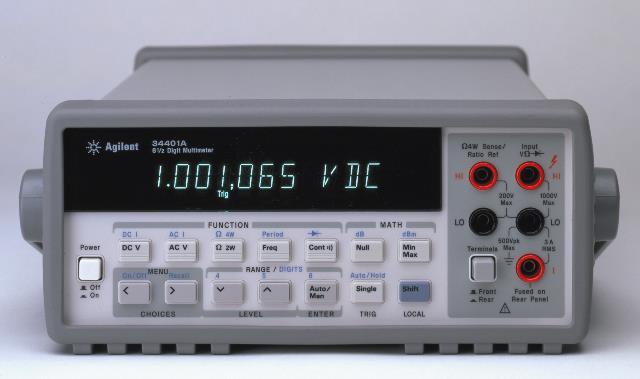
2 Electrical Engineer 35 years in the Test and Measurement Industry HP, Agilent, Keysight Technologies Author of Electronic Test Instruments Spectrum and Network Measurements 2
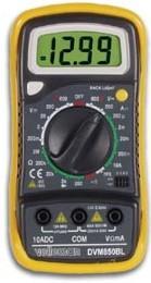
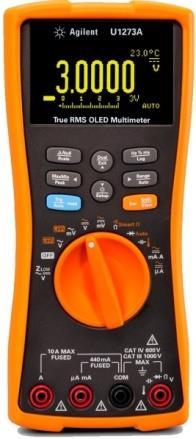
3 The Multimeter Measures DC/AC Voltage, Current and Resistance Antenna System Measurements The SWR Meter The Antenna Analyzer 3
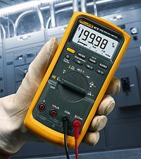
4 Also known as voltmeter, VOM (Volt-Ohm-mA meter),dvm (Digital Voltmeter), or DMM (Digital Multimeter) Voltmeter, ammeter and ohmmeter combined into one instrument DC and AC measurements Some models have diode test, continuity, capacitance, inductance, frequency, temperature Bench or handheld form factor Mostly digital meters, some analog meters 4
5 5
6 "Digital" is derived from the word "Digit" which means finger. Be careful where you put your digits when using a Digital Multimeter Safety First Graphic courtesy of Agilent Technologies 6
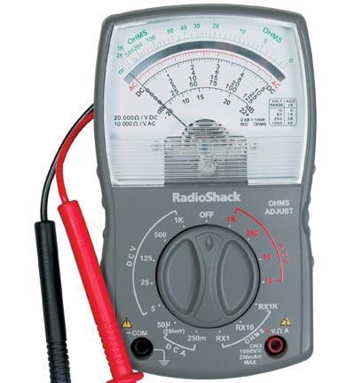
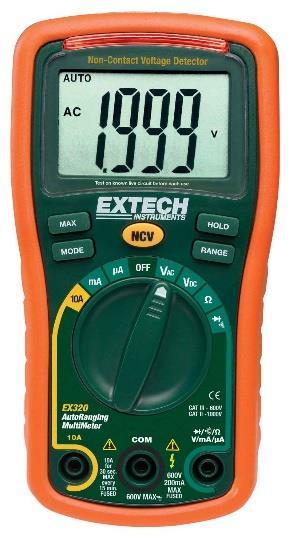
7 What? You don't have a Multimeter? Buy a digital meter (forget the analog ones) Should have a minimum of 600 V Cat II (IEC 1010) rating Should have DC volts, AC volts, resistance and DC current (might not have AC current) Other features to consider: Continuity test mode ( beeper ) Diode test mode Autorange Analog Bar graph Battery test mode True RMS 7
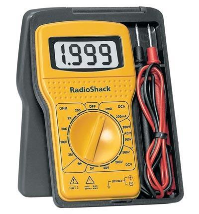
8 8 Innova 3320 Price ~$20 3½ Digits 0.8% to 1.5% Accuracy (depends on range) Diode test Continuity test Autorange Battery test IEC 1010 Cat II - 600V
 Beeper Protection")
9 DMM IC (under glop) Two AA batteries Quad Op Amp (LM324) Beeper Protection Fuse 9
10 Current I E Battery R Resistor Ohm's Law: I=E/R Note: Positive current convention used 10
11 Voltmeter E V Configure DMM to DC voltage DMM appears as open circuit Connect DMM in parallel with voltage to be measured 11

12 Configure DMM to DC Current DMM appears as short circuit Connect DMM in series with current to be measured A Don't select current mode by mistake Be very careful how you connect when in current mode Short circuits can cause big problems! Be Careful!!!!!!! 12
13 Configure DMM to Resistance Remove power from the circuit DMM provides power to the circuit being tested Connect DMM in parallel with the resistance to be measured Make sure there is nothing else in parallel with the resistor E R Ohmmeter Ω These principles also apply to diode test, capacitance test, inductance test, continuity test, etc. 13

14 Let s measure it. 120 Volts RMS ± 6 V Put DMM in AC Voltage mode and plug er in 14
15 Sine Wave Voltage Measurements V RMS V P V PP V RMS = V P V P = V RMS (sine wave) 15
16 Some Superfluous Math Equations General Equations V RMS T 1 2 T v ( t ) 0 dt V AVG 1 T T 0 v( t) dt For Sine Wave 1 V V RMS T 1 2 V T psin (2 ft) dt VP 0 2 P 1 2 V V V AVG T VP sin(2 ft) dt T 0 P P 16
17 Example: AC Line Voltage V RMS = 120 volts V P =170 volts V PP = 340 volts V RMS = V P V P = V RMS (sine wave) 17
18 Specification: 120 Volts RMS ± 6 V 18

19 Current measurement is done via clamping the wire The clamp acts as the core of a transformer AC-only current measurement Uni-Trend UT202A $28 on Amazon Clamp meters are available that measure DC current but are more expensive 19


20 Inserted inline with AC power cord Allows easy attachment of clamp-on ammeter Also has slots for probing voltage 20
21 P = I E P = power E = voltage I = current E Load + - Current I 21
22 22
23 Antenna Measurements SWR = Standing Wave Ratio, more properly called Voltage Standing Wave Ratio (VSWR) Measures the match between source (transmitter) and load (antenna). Perfect match is SWR = 1.0 (1:1) Anything greater than 1.0 is less than perfect SWR is always
24 More Superfluous Math Equations

25 V F + V R SWR = V F - V R Transceiver V R reflected voltage Antenna Transmission Line V F forward voltage Transceiver, transmission line and antenna are all nominally the same impedance (50 ohms for amateur radio work). 25
26 What is the impedance looking into this port? Z = R + jx SWR = Z L /Z 0 or Z 0 /Z L whichever is 1, for Z L real Example: What is the SWR with Z L =100Ω? SWR = 100/50 = 2 Transmission Line Z 0 =50 Ω Antenna ρ = reflection coefficient= V R /V F RL = return loss (db) = -20 log (ρ) 26
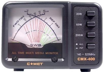
27 V R reflected voltage Antenna Transceiver SWR Meter V F forward voltage Transmission Line SWR meter is inserted into the transmission line, which usually requires an additional cable between transceiver and SWR meter. 27

28 Diamond SX-200 SWR/Power Meter SWR and Power Meter Freq Range: MHz Power Ranges: 5W, 20W and 200 W Price: ~$100 28


29 Note the use of the cross-needle meter to avoid the need to cal the measurement 29

30 V R reflected voltage Antenna Transceiver SWR Meter V F forward voltage Transmission Line With no transmission line loss, the SWR measurement is the same anywhere on the line (ideal conditions) With line loss, the reflected voltage may be significantly attenuated, resulting in a lower SWR reading. High transmission line loss makes your antenna system seem better Move the meter closer to the antenna 30
31 SWR meters measure the match at the point of insertion. When measuring/adjusting an antenna, put the SWR meter as close to the antenna as possible. Make sure the SWR meter is spec d for the frequency of interest. Long, lossy coax makes the SWR look better. How low should the SWR be? Depends on the situation...what can be reasonably expected? It might be OK to run high SWR. 31
32 SWR does not indicate whether your antenna is resonant SWR does not measure the efficiency of your antenna SWR does not indicate how well your signal is being radiated An SWR measurement just tells you the impedance match at the point the meter is inserted into the transmission line 32
33 33
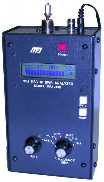
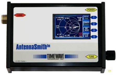
34 Frequency Range: MHz Price: ~$250 Measure: SWR, Return Loss Impedance, Reactance, Resistance Default measurement mode is: - Impedance, Z = R + j X (R= resistance, X = reactance) - SWR Also: Impedance, Z = Z mag Reflection coefficient Return Loss 34

35 35
36 VFO MHz 50Ω RF Bridge Test Port +7 dbm, ~0.5 Vrms Frequency Counter Analog voltages Microcontroller Display & Controls 36
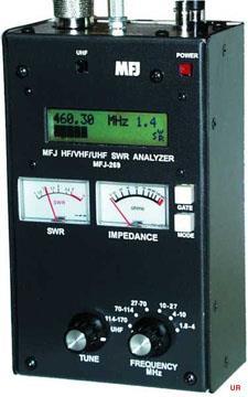
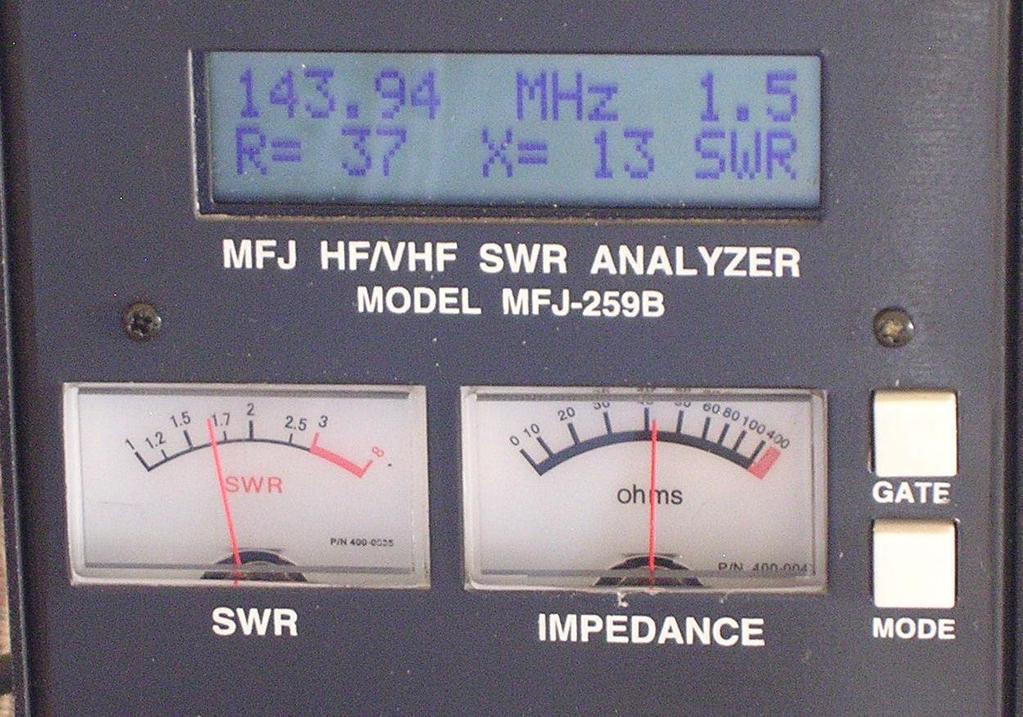
37 MFJ-259B Antenna Analyzer Usage Tips Best accuracy near 50 ohms (SWR=1) Don't use in high RF environment Input circuitry is sensitive Discharge antennas before connecting Do not apply external voltages to test port Don't over-interpret the results (the analyzer is just looking at the impedance match against 50W) 37

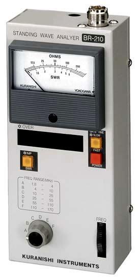
38 Frequency Range: 1.8 to 500 MHz Price: ~$430 38


39 Measure SWR, Return Loss, Cable Loss 100 khz to 230 MHz. Graphical display plots SWR versus frequency Time Domain Reflectometer mode can be used to locate the precise location of a fault within the feedline system. ~$550 39
40 Basic Test Equipment for Ham Use Digital Multimeter SWR Meter Antenna Analyzer Safety First Always be careful with electrical measurements (especially high voltage) 40 This presentation is available for download at k0nr.com
41 41
RM Ham University December Bob Witte, KØNR Monument, CO
 RM Ham University December 2018 Bob Witte, KØNR bob@k0nr.com Monument, CO Electrical Engineer 40 years in the Test and Measurement Industry HP, Agilent, Keysight Technologies Author of Electronic Test
The Amazing MFJ 269 Author Jack Tiley AD7FO
 The Amazing MFJ 269 Author Jack Tiley AD7FO ARRL Certified Emcomm and license class Instructor, Volunteer Examiner, EWA Technical Coordinator and President of the Inland Empire VHF Club What Can be Measured?
Experiment 1: Instrument Familiarization (8/28/06)
") Electrical Measurement Issues Experiment 1: Instrument Familiarization (8/28/06) Electrical measurements are only as meaningful as the quality of the measurement techniques and the instrumentation applied
Electrical Measurement Issues Experiment 1: Instrument Familiarization (8/28/06) Electrical measurements are only as meaningful as the quality of the measurement techniques and the instrumentation applied
Experiment 1: Instrument Familiarization
 Electrical Measurement Issues Experiment 1: Instrument Familiarization Electrical measurements are only as meaningful as the quality of the measurement techniques and the instrumentation applied to the
MFJ 259 Operation & Simplified Calibration
 MFJ 259 Operation & Simplified Calibration Bill Leonard N0CU NA0TC 2014 TechFest 1 What Will Be Covered Part 1: Operation What is an MFJ 259 What Does It Measure Impedance & Admittance How Does It Work
Transmission lines. Characteristics Applications Connectors
 Transmission lines Characteristics Applications Connectors Transmission Lines Connect They allow us to conduct RF Signals between our station components, they connect: Transceivers Antennas Tuners Amplifiers
DIGITAL MULTIMETERS. Accuracy +5% Resolution 1pF Accessories Test leads, Manual, 9V Battery included Options ST-265, C-90, C W x 6 L x 1.
 DIGITAL MULTIMETERS Model M-1700 Model M-2775 Frequency to 20MHz Diode and Transistor Test AC/DC Current to 10A Three Way Overload Protection Extra Large 1 display test Data Hold Frequency to 20MHz Transistor
The University of Jordan Mechatronics Engineering Department Electronics Lab.( ) Experiment 1: Lab Equipment Familiarization
 Experiment 1: Lab Equipment Familiarization") The University of Jordan Mechatronics Engineering Department Electronics Lab.(0908322) Experiment 1: Lab Equipment Familiarization Objectives To be familiar with the main blocks of the oscilloscope and
The University of Jordan Mechatronics Engineering Department Electronics Lab.(0908322) Experiment 1: Lab Equipment Familiarization Objectives To be familiar with the main blocks of the oscilloscope and
Review: The MFJ-225 Graphical Antenna Analyzer Phil Salas AD5X
 Review: The Graphical Antenna Analyzer Phil Salas AD5X The has a back-lit 3 LCD graphic display that simultaneously shows the frequency or swept frequency range, unsigned complex impedance, impedance magnitude,
Calibration Techniques for the Home Lab
 Calibration Techniques for the Home Lab Jacques Audet VE2AZX jacaudet@videotron.ca Web: ve2azx.net September 2018 ve2azx.net 1 Summary - Using a reference multimeter as a calibrator for less accurate instruments.
Agilent 970-Series Handheld Multimeters Data Sheet
 Agilent 970-Series Handheld Multimeters Data Sheet Benchtop features and performance with handheld convenience and price 3 1 /2and 4 1 /2 digits with dcv accuracy to 0.05% 1 khz to 100 khz frequency response
79/26 Series III Multimeter
 79/26 Series III Multimeter Instruction Sheet W Read First: Safety Information Never use the meter if the meter or test leads look damaged. Be sure the test leads and switch are in the correct position
RigExpert AA-170 Antenna Analyzer (0.1 to 170 MHz) User s manual
 User s manual") RigExpert AA-170 Antenna Analyzer (0.1 to 170 MHz) User s manual Table of contents 1. Description... 3 2. Specifications... 4 3. Precautions... 5 4. Operation... 6 4.1. Preparation for use... 6 4.2. Turning
RigExpert AA-170 Antenna Analyzer (0.1 to 170 MHz) User s manual Table of contents 1. Description... 3 2. Specifications... 4 3. Precautions... 5 4. Operation... 6 4.1. Preparation for use... 6 4.2. Turning
Electronic Instrument Disadvantage of moving coil meter Low input impedance High loading error for low-voltage range voltmeter
 EIE 240 Electrical and Electronic Measurement Class 6, February 20, 2015 1 Electronic Instrument Disadvantage of moving coil meter Low input impedance High loading error for low-voltage range voltmeter
This paper is meant assist in the operation and understanding of the VIA Bravo Family of products.
 Abstract: This paper is meant assist in the operation and understanding of the VIA Bravo Family of products. Understanding the Display and its Readings: The VIA Bravo display provides graphical and numerical
Preliminary Users Manual for the Self Contained Return Loss and Cable Fault Test Set with Amplified Wideband Noise Source Copyright 2001 Bryan K.
 Preliminary Users Manual for the Self Contained Return Loss and Cable Fault Test Set with Amplified Wideband Noise Source Copyright 2001 Bryan K. Blackburn Self Contained Test Set Test Port Regulated 12
ECE 4670 Spring 2014 Lab 1 Linear System Characteristics
 ECE 4670 Spring 2014 Lab 1 Linear System Characteristics 1 Linear System Characteristics The first part of this experiment will serve as an introduction to the use of the spectrum analyzer in making absolute
Lesson 11: Antennas. Copyright Winters Version 1.0. Preparation for Amateur Radio Technician Class Exam
 Lesson 11: Antennas Preparation for Amateur Radio Technician Class Exam Topics Antenna ½ wave Dipole antenna ¼ wave Vertical antenna Antenna polarization Antenna location Beam antennas Test Equipment Exam
AA-35 ZOOM. RigExpert. User s manual. Antenna and cable analyzer
 AA-35 ZOOM Antenna and cable analyzer RigExpert User s manual . Table of contents Introduction Operating the AA-35 ZOOM First time use Main menu Multifunctional keys Connecting to your antenna SWR chart
Build a Return Loss Bridge
 Build a Return Loss Bridge Used with your DVM, this simple bridge, diode detector and return loss techniques can help you measure cable loss and SWR at the antenna. The bridge does double duty as a hybrid
MFJ-249B HF/VHF SWR ANALYZER
 TABLE OF CONTENTS MFJ-249B... 2 Introduction... 2 Powering The MFJ-249B... 3 Battery Installation... 3 Alkaline Batteries... 3 NiCd Batteries... 4 Power Saving Mode... 4 Operation Of The MFJ-249B...5 SWR
Technician Licensing Class. Lesson 4. presented by the Arlington Radio Public Service Club Arlington County, Virginia
 Technician Licensing Class Lesson 4 presented by the Arlington Radio Public Service Club Arlington County, Virginia 1 Quiz Sub elements T6 & T7 2 Good Engineering Practice Sub element T8 3 A Basic Station
Generic Lab Manual: An overview on the major functionalities of the equipment.
 Generic Lab Manual: This being a generic lab manual is not a complete description or tutorial on everything that the test equipment is capable of measuring. But rather a quick guide on how each piece of
U1604A Handheld Oscilloscopes, 40 MHz
 Products & Services Technical Support Buy Industries About Agilent Search: All Test & Measurement Go United States Home >... > Oscilloscopes > U1600A Series handheld oscilloscopes (2 models) > U1604A Handheld
DC Circuits, Ohm's Law and Multimeters Physics 246
 DC Circuits, Ohm's Law and Multimeters Physics 246 Theory: In this lab we will learn the use of multimeters, verify Ohm s law, and study series and parallel combinations of resistors and capacitors. For
Transmission Lines As Impedance Transformers
 Transmission Lines As Impedance Transformers Bill Leonard N0CU 285 TechConnect Radio Club 2017 TechFest Topics Review impedance basics Review Smith chart basics Demonstrate how antenna analyzers display
Technician License. Course
 Technician License Course Technician License Course Chapter 4 Lesson Plan Module - 9 Antenna Fundamentals Feed Lines & SWR The Antenna System The Antenna System Antenna: Transforms current into radio waves
Instrument Usage in Circuits Lab
 Instrument Usage in Circuits Lab This document contains descriptions of the various components and instruments that will be used in Circuit Analysis laboratory. Descriptions currently exist for the following
Technician License Course Chapter 3. Lesson Plan Module 4 Electricity
 Technician License Course Chapter 3 Lesson Plan Module 4 Electricity Fundamentals of Electricity Radios are powered by electricity and radio signals are a form of electrical energy. A basic understanding
MFJ-834 RF Ammeter. Introduction. Uses
 MFJ-834 RF Ammeter Introduction Congratulations on purchasing the MFJ-834 RF Ammeter. The MFJ-834 is designed for measuring in-line RF feedline current on 1.8-30 MHz while having low interaction on the
ENGR 120 LAB #2 Electronic Tools and Ohm s Law
 ENGR 120 LAB #2 Electronic Tools and Ohm s Law Objectives Understand how to use a digital multi-meter, power supply and proto board and apply that knowledge to constructing circuits to demonstrate ohm
Laboratory 2 (drawn from lab text by Alciatore)
") Laboratory 2 (drawn from lab text by Alciatore) Instrument Familiarization and Basic Electrical Relations Required Components: 2 1k resistors 2 1M resistors 1 2k resistor Objectives This exercise is designed
Laboratory 2 (drawn from lab text by Alciatore) Instrument Familiarization and Basic Electrical Relations Required Components: 2 1k resistors 2 1M resistors 1 2k resistor Objectives This exercise is designed
ABCs of DMMs Multimeter features and functions explained Application Note
 ABCs of DMMs Multimeter features and functions explained Application Note Digital multimeters offer a wide selection of features. Choosing the right meter for the job can be challenging unless you know
Amateur Extra Manual Chapter 9.4 Transmission Lines
 9.4 TRANSMISSION LINES (page 9-31) WAVELENGTH IN A FEED LINE (page 9-31) VELOCITY OF PROPAGATION (page 9-32) Speed of Wave in a Transmission Line VF = Velocity Factor = Speed of Light in a Vacuum Question
Notes on Experiment #3
 Notes on Experiment #3 This week you learn to measure voltage, current, and resistance with the digital multimeter (DMM) You must practice measuring each of these quantities (especially current) as much
ABCs of DMMs. Multimeter features and functions explained. Application Note. Introduction. Choosing your DMM. Some basics
 ABCs of DMMs Multimeter features and functions explained Application Note Introduction Multimeters. They ve been described as the tape measure of the new millennium. But what exactly is a digital multimeter
SOME USES FOR RF1,RF5 and VA1 ANALYSTS. SWR Measurement
 SOME USES FOR RF1,RF5 and VA1 ANALYSTS THE HANDIEST INSTRUMENTS IN DECADES! When you put up an antenna in the the old days, it could be a real struggle. The only way to tell if it was tuned to the right
PHYS 1402 General Physics II Experiment 5: Ohm s Law
 PHYS 1402 General Physics II Experiment 5: Ohm s Law Student Name Objective: To investigate the relationship between current and resistance for ordinary conductors known as ohmic conductors. Theory: For
Fluke 8845A/8846A Digital Multimeters Extended Specifications
 Fluke 8845A/8846A Digital Multimeters Extended Specifications The Fluke 8845A and 8846A 6.5 digit precision multimeters have the precision and versatility to handle your most demanding measurements, on
Agilent U1253B True RMS OLED Multimeter. Quick Start Guide
 Agilent U1253B True RMS OLED Multimeter Quick Start Guide The following items are included with your multimeter: Silicone test leads 4 mm probes Alligator clips Printed Quick Start Guide Rechargeable 8.4
FM Modulation. Accuracy. Total. Harmonics. Input Range. Frequency. Range. Deviation. Range. Modulation. Accuracy. Audio In Switchable Loads.
 Product Specification VIAVI 3550R Touch-Screen Radio Test System VIAVI Solutions General Specifications RF Signal Generator Output SSB Phase Noise 2 MHz - 1 GHz (usable from 500 khz) T/R Port: -50 to -125
Entry Level Assessment Blueprint Electronics Technology
 Blueprint Test Code: 4135 / Version: 01 Specific Competencies and Skills Tested in this Assessment: Safety Practices Demonstrate safe working procedures Explain the purpose of OSHA and how it promotes
Microwave Circuit Design and Measurements Lab. INTRODUCTION TO MICROWAVE MEASUREMENTS: DETECTION OF RF POWER AND STANDING WAVES Lab #2
 EE 458/558 Microwave Circuit Design and Measurements Lab INTRODUCTION TO MICROWAVE MEASUREMENTS: DETECTION OF RF POWER AND STANDING WAVES Lab #2 The purpose of this lab is to gain a basic understanding
Module 1, Lesson 2 Introduction to electricity. Student. 45 minutes
 Module 1, Lesson 2 Introduction to electricity 45 minutes Student Purpose of this lesson Explanations of fundamental quantities of electrical circuits, including voltage, current and resistance. Use a
EE283 Laboratory Exercise 1-Page 1
 EE283 Laboratory Exercise # Basic Circuit Concepts Objectives:. To become familiar with the DC Power Supply unit, analog and digital multi-meters, fixed and variable resistors, and the use of solderless
DVM645BI BENCH MULTIMETER TAFELMULTIMETER MULTIMETRE DE TABLE BANCO MULTÍMETRO TISCHMULTIMETER. User Manual. Gebruikershandleiding
 BENCH MULTIMETER TAFELMULTIMETER MULTIMETRE DE TABLE BANCO MULTÍMETRO TISCHMULTIMETER User Manual Gebruikershandleiding Manuel d'utilisation Gebrauchsanleitung Introduction BENCH MULTIMETER This manual
2. BAND-PASS NOISE MEASUREMENTS
 2. BAND-PASS NOISE MEASUREMENTS 2.1 Object The objectives of this experiment are to use the Dynamic Signal Analyzer or DSA to measure the spectral density of a noise signal, to design a second-order band-pass
User manual. / verzió 1.0 /
 User manual / verzió 1.0 / Budapest, 2017 "Antenna Analyzer plus" is a multifunctional measuring instrument, most useful for amateur radio activity. Its size allows you to easily take it for relocation
Digital Clamp Meter Model: &
 Digital Clamp Meter Model: 72-7224 & 72-7226 1 SAFETY INFORMATION Please read these instructions carefully before use and retain for future reference. This meter is designed to meet IEC61010-1, 61010-2-032,
Notes on Experiment #3
 Notes on Experiment #3 This week you learn to measure voltage, current, and resistance with the digital multimeter (DMM) You must practice measuring each of these quantities (especially current) as much
MFJ-219/219N 440 MHz UHF SWR Analyzer TABLE OF CONTENTS
 MFJ-219/219N 440 MHz UHF SWR Analyzer TABLE OF CONTENTS Introduction...2 Powering The MFJ-219/219N...3 Battery Installation...3 Operation Of The MFJ-219/219N...4 SWR and the MFJ-219/219N...4 Measuring
Lab #1 Lab Introduction
 Cir cuit s 212 Lab Lab #1 Lab Introduction Special Information for this Lab s Report Because this is a one-week lab, please hand in your lab report for this lab at the beginning of next week s lab. The
Receiver Specification?
 Receiver Specification? What do they mean? Steve Finch AIØW What We re Doing Today Stage-by-stage receiver gain what do they mean? Specifications of interest why? Test equipment needed Learn about the
U1571A Ni-MH Battery Pack for U1600A Handheld Oscilloscopes
 United States Home >... > Oscilloscope Accessories > U1600 Series Oscilloscope Accessories > U1571A Ni-MH Battery Pack for U1600A Handheld Oscilloscopes Key Specifications Features Ni-MH Battery Pack,
Technician License Course Chapter 4. Lesson Plan Module 9 Antenna Fundamentals, Feed Lines & SWR
 Technician License Course Chapter 4 Lesson Plan Module 9 Antenna Fundamentals, Feed Lines & SWR The Antenna System Antenna: Transforms current into radio waves (transmit) and vice versa (receive). Feed
Technician Licensing Class. Antennas
 Technician Licensing Class Antennas Antennas A simple dipole mounted so the conductor is parallel to the Earth's surface is a horizontally polarized antenna. T9A3 Polarization is referenced to the Earth
MFJ-835 RF Ammeter. Introduction. Uses
 MFJ-835 RF Ammeter Introduction Congratulations on purchasing the MFJ-835 Balanced Line RF Ammeter. The MFJ-835 is designed for measuring balanced RF feedline current on 1.8-30 MHz while having low interaction
FCC Technician License Course
 FCC Technician License Course 2018-2022 FCC Element 2 Technician Class Question Pool Presented by: Tamiami Amateur Radio Club (TARC) WELCOME To the SECOND of 3, 4-hour classes presented by TARC to prepare
Technician Licensing Class T9
 Technician Licensing Class T9 Amateur Radio Course Monroe EMS Building Monroe, Utah January 11/18, 2014 January 22, 2014 Testing Session Valid dates: July 1, 2010 June 30, 2014 Amateur Radio Technician
Installed Radio Testing with the 3500
 Application Note Installed Radio Testing with the 3500 Aeroflex has uniquely designed the Aeroflex 3500 portable radio test set for complete testing of installed radio communication systems. The 3500 is
Understanding the Precision Antenna, Cable, and Power Measurements on the 3550 Radio Test System
 Application Note Understanding the Precision Antenna, Cable, and Power Measurements on the 3550 Radio Test System The Aeroflex 3550 Radio Test System now includes new methods for more accurately measuring
PHYSICS 221 LAB #6: CAPACITORS AND AC CIRCUITS
 Name: Partners: PHYSICS 221 LAB #6: CAPACITORS AND AC CIRCUITS The electricity produced for use in homes and industry is made by rotating coils of wire in a magnetic field, which results in alternating
OHM'S LAW AND RESISTANCE NETWORKS OBJECT
 17 E7 E7.1 OHM'S LAW AND RESISTANCE NETWORKS OBJECT The objects of this experiment are to determine the voltage-current relationship for a resistor and to verify the series and parallel resistance formulae.
The Art of Electrical Measurements
 The Art of Electrical Measurements Purpose: Introduce fundamental electrical test and measurement tools and the art of making electrical measurements. Equipment Required Prelab 1 Digital Multimeter 1 -
SWR myths and mysteries.
 SWR myths and mysteries. By Andrew Barron ZL3DW September 2012 This article will explain some of the often misunderstood facts about antenna SWR at HF and uncover some popular misconceptions. The questions
MEASUREMENTS & INSTRUMENTATION ANALOG AND DIGITAL METERS
 MEASUREMENTS & INSTRUMENTATION ANALOG AND DIGITAL METERS ANALOG Metering devices Provides monotonous (continuous) movement. ELECTRICAL MEASURING INSTRUMENTS ANALOG METERS A d Arsonval galvanometer (Moving
COAXIAL TRANSMISSION LINE COMMON-MODE CURRENT
 COAXIAL TRANSMISSION LINE COMMON-MODE CURRENT Introduction Coaxial transmission lines are popular for their wide frequency bandwidth and high resistance to electromagnetic interference (EMI). Coax cables
EE Chapter 7 Measuring Instruments
 EE 2145230 Chapter 7 Measuring Instruments 7.1 Meter Movements The basic principle of many electric instruments is that of the galvanometer. This is a device which reacts to minute electromagnetic influences
Chapter 6 Antenna Basics. Dipoles, Ground-planes, and Wires Directional Antennas Feed Lines
 Chapter 6 Antenna Basics Dipoles, Ground-planes, and Wires Directional Antennas Feed Lines Some General Rules Bigger is better. (Most of the time) Higher is better. (Most of the time) Lower SWR is better.
P a g e 1 ST985. TDR Cable Analyzer Instruction Manual. Analog Arts Inc.
 P a g e 1 ST985 TDR Cable Analyzer Instruction Manual Analog Arts Inc. www.analogarts.com P a g e 2 Contents Software Installation... 4 Specifications... 4 Handling Precautions... 4 Operation Instruction...
Exercise 9: inductor-resistor-capacitor (LRC) circuits
 circuits") Exercise 9: inductor-resistor-capacitor (LRC) circuits Purpose: to study the relationship of the phase and resonance on capacitor and inductor reactance in a circuit driven by an AC signal. Introduction
Exercise 9: inductor-resistor-capacitor (LRC) circuits Purpose: to study the relationship of the phase and resonance on capacitor and inductor reactance in a circuit driven by an AC signal. Introduction
RLC Frequency Response
 1. Introduction RLC Frequency Response The student will analyze the frequency response of an RLC circuit excited by a sinusoid. Amplitude and phase shift of circuit components will be analyzed at different
Instructions for the final examination:
 School of Information, Computer and Communication Technology Sirindhorn International Institute of Technology Thammasat University Practice Problems for the Final Examination COURSE : ECS304 Basic Electrical
Least understood topics by most HAMs RF Safety Ground Antennas Matching & Feed Lines
 Least understood topics by most HAMs RF Safety Ground Antennas Matching & Feed Lines Remember this question from the General License Exam? G0A03 (D) How can you determine that your station complies with
Keysight 34401A Multimeter
 Keysight 34401A Multimeter Data Sheet See Keysight's Truevolt Series of DMMs You also get both GPIB and RS-232 interfaces as standard features. Voltmeter Complete and External Trigger signals are provided
AVL-10000T AUDIO VIDEO LINK TRANSMITTER TECHNICAL MANUAL
 AVL-10000T AUDIO VIDEO LINK TRANSMITTER TECHNICAL MANUAL Document : AVL-10000T Version: 1.00 Author: Henry S Date: 25 July 2008 This module contains protection circuitry to guard against damage due to
ME 365 EXPERIMENT 1 FAMILIARIZATION WITH COMMONLY USED INSTRUMENTATION
 Objectives: ME 365 EXPERIMENT 1 FAMILIARIZATION WITH COMMONLY USED INSTRUMENTATION The primary goal of this laboratory is to study the operation and limitations of several commonly used pieces of instrumentation:
The Principle V(SWR) The Result. Mirror, Mirror, Darkly, Darkly
 The Result. Mirror, Mirror, Darkly, Darkly") The Principle V(SWR) The Result Mirror, Mirror, Darkly, Darkly 1 Question time!! What do you think VSWR (SWR) mean to you? What does one mean by a transmission line? Coaxial line Waveguide Water pipe Tunnel
The Principle V(SWR) The Result Mirror, Mirror, Darkly, Darkly 1 Question time!! What do you think VSWR (SWR) mean to you? What does one mean by a transmission line? Coaxial line Waveguide Water pipe Tunnel
Model 77 Series IV. Digital Multimeter. Users Manual
 Model 77 Series IV Digital Multimeter Users Manual Model 77 Series IV Digital Multimeter The Fluke Model 77 Series IV is a battery-powered, average responding-rms indicating multimeter (hereafter "the
ECE 231 Laboratory Exercise 3 Oscilloscope/Function-Generator Operation ECE 231 Laboratory Exercise 3 Oscilloscope/Function Generator Operation
 ECE 231 Laboratory Exercise 3 Oscilloscope/Function Generator Operation Laboratory Group (Names) OBJECTIVES Gain experience in using an oscilloscope to measure time varying signals. Gain experience in
MFJ-208 VHF SWR Analyzer
 MFJ-208 VHF SWR Analyzer Thank you for purchasing the MFJ-208 VHF SWR Analyzer. The MFJ-208 gives you a direct readout of your antenna's SWR without the need for formulas or indirect readings. The MFJ-
87415A microwave system amplifier A microwave. system amplifier A microwave system amplifier A microwave.
 20 Amplifiers 83020A microwave 875A microwave 8308A microwave 8307A microwave 83006A microwave 8705C preamplifier 8705B preamplifier 83050/5A microwave The Agilent 83006/07/08/020/050/05A test s offer
The object of this experiment is to become familiar with the instruments used in the low noise laboratory.
 0. ORIENTATION 0.1 Object The object of this experiment is to become familiar with the instruments used in the low noise laboratory. 0.2 Parts The following parts are required for this experiment: 1. A
MS8268 HANDHELD DIGITAL MULTIMETER OPERATOR S INSTRUCTION MANUAL
 MS8268 HANDHELD DIGITAL MULTIMETER OPERATOR S INSTRUCTION MANUAL Table of Contents TITLE PAGE 1. GENERAL INSTRUCTIONS 1 1.1 Precaution safety measures 1 1.1.1 Preliminary 1 1.1.2 During use 2 1.1.3 Symbols
EXAMPLE. Use this jack for the red test lead when measuring. current from 0 to 200mA. Figure P-1
 Digital Multimeters ON / OFF power switch Continuity / Diode Test Function Resistance Function Ranges from 200Ω to 200MΩ Transistor Test Function DC Current Function Ranges from 2mA to 20A. AC Current
4/25/2012. Supplement T9. 2 Exam Questions, 2 Groups. Amateur Radio Technician Class T9A: T9A: T9A: T9A:
 Amateur Radio Technician Class Element 2 Course Presentation ti ELEMENT 2 SUB-ELEMENTS Technician Licensing Class Supplement T9 Antennas, Feedlines 2 Exam Questions, 2 Groups T1 - FCC Rules, descriptions
Lab #5 Steady State Power Analysis
 Lab #5 Steady State Power Analysis Steady state power analysis refers to the power analysis of circuits that have one or more sinusoid stimuli. This lab covers the concepts of RMS voltage, maximum power
0.5% Accuracy Overload Fuse protection Test Clips/Direct insert jack for easy measurement TES Capacitance Meter
 TES-1500 Capacitance 0.5% Accuracy Overload Fuse protection Test Clips/Direct insert jack for easy measurement TES-2620 TRMS Multimeter TES-2700 TES-2712 LCR Multimeter 3-3/4 Digital LCD with bar-graph
Agilent U1251B and U1252B Handheld Digital Multimeter. Quick Start Guide
 Agilent U1251B and U1252B Handheld Digital Multimeter Quick Start Guide The following items are included with your multimeter: Silicone test leads 4 mm probes Alligator clips Printed Quick Start Guide
University of Jordan School of Engineering Electrical Engineering Department. EE 204 Electrical Engineering Lab
 University of Jordan School of Engineering Electrical Engineering Department EE 204 Electrical Engineering Lab EXPERIMENT 1 MEASUREMENT DEVICES Prepared by: Prof. Mohammed Hawa EXPERIMENT 1 MEASUREMENT
Meters and Test Equipment
 Installation Knowledge and Techniques Meters and Test Equipment OBJECTIVES Meters and Test Equipment DMM s and VOM s Describe the difference between a DMM and a VOM. Describe the methods for measuring
RF Characterization Report
 SMA-J-P-H-ST-MT1 Mated with: RF316-01SP1-01BJ1-0305 Description: 50-Ω SMA Board Mount Jack, Mixed Technology Samtec, Inc. 2005 All Rights Reserved Table of Contents Introduction...1 Product Description...1
IDEAL INDUSTRIES, INC. TECHNICAL MANUAL MODEL: MODEL: Multimeter Service Information
 IDEAL INDUSTRIES, INC. TECHNICAL MANUAL MODEL: 61-340 MODEL: 61-342 Multimeter Service Information The Service Information provides the following information: Precautions and safety information Specifications
Vector Network Analyzers. Paul Coverdale VE3ICV
 Paul Coverdale VE3ICV What is a vector network analyzer? What is a vector? A vector is a quantity having magnitude and direction A vector can be described in rectangular (X,Y) or polar ( Z θ) notation
+ A Supply B. C Load D
 17 E7 E7.1 OHM'S LAW AND RESISTANCE NETWORKS OBJECT The objects of this experiment are to determine the voltage-current relationship for a resistor and to verify the series and parallel resistance formulae.
Group: Names: Resistor Band Colors Measured Value ( ) R 1 : 1k R 2 : 1k R 3 : 2k R 4 : 1M R 5 : 1M
 R 1 : 1k R 2 : 1k R 3 : 2k R 4 : 1M R 5 : 1M") 2.4 Laboratory Procedure / Summary Sheet Group: Names: (1) Select five separate resistors whose nominal values are listed below. Record the band colors for each resistor in the table below. Then connect
2.4 Laboratory Procedure / Summary Sheet Group: Names: (1) Select five separate resistors whose nominal values are listed below. Record the band colors for each resistor in the table below. Then connect
Review: The MFJ-223 Vector Impedance Antenna Analyzer Phil Salas AD5X
 Review: The Vector Impedance Antenna Analyzer Phil Salas AD5X The is MFJ s latest entry in the antenna analyzer market. Its TFT multi-color display provides a large amount of information on a very compact
Amateur Radio Examination EXAMINATION PAPER No. 275 MARKER S COPY
 01-6-(d) An Amateur Station is quoted in the regulations as a station: a for training new radio operators b using amateur equipment for commercial purposes c for public emergency purposes d in the Amateur
DEPARTMENT OF ELECTRICAL ENGINEERING LAB WORK EE301 ELECTRONIC CIRCUITS
 DEPARTMENT OF ELECTRICAL ENGINEERING LAB WORK EE301 ELECTRONIC CIRCUITS EXPERIMENT : 5 TITLE : ACTIVE FILTERS OUTCOME : Upon completion of this unit, the student should be able to: 1. gain experience with
Trees, vegetation, buildings etc.
 EMC Measurements Test Site Locations Open Area (Field) Test Site Obstruction Free Trees, vegetation, buildings etc. Chamber or Screened Room Smaller Equipments Attenuate external fields (about 100dB) External