Medidores de vibración salida RS232 Datalogger VT-8204 LUTRON manual ingles
|
|
|
- Natalie Ramsey
- 5 years ago
- Views:
Transcription

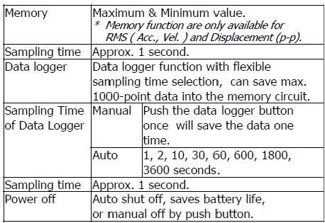
1 English usermanual VT-8204 Vibration Tachometer Your purchase of this VIBRATION TACHOMETER marks a step forward for you into the field of precision measurement. Although this VIBRATION TACHOMETER is a complex and delicate instrument, its durable structure will allow many years of use if proper operating techniques are developed. Please read the following instructions carefully and always keep this manual within easy reach. Features Vibration function : * Applications for industrial vibration monitoring : All industrial machinery vibrates. The level of vibration is a useful guide to machine condition. Poor balance, misalignment & looseness of the structure will cause the vibration level increase, it is a sure sign that the maintenance is needed. * Acceleration range : 200 m/s^2. * Velocity range : 200 mm/s. * Displacement ( p-p ) range : 2 mm. * Metric and imperial display unit. * RMS measurement for Acceleration and Velocity. * Peak to peak measurement for Displacement. * Peak function for Acceleration and Velocity. * Max. hold function for Acceleration ( peak ), Velocity ( peak ) and Displacement ( peak to peak ). * Frequency range 10 Hz - 1 khz, sensitivity relative meet ISO * Zero function, executed by front buttons. * Data logger function with flexible sampling time selection, can save max point data into the memory circuit. * Data hold button to freeze the desired reading. * Memory function to record maximum and minimum reading of RMS value ( Acc., Vel. ) or Displacement ( p-p ). * Auto shut off saves battery life. * Professional vibration meter supply with separate vibration sensor & magnetic base, full set. Tachometer ( photo, contact ) function : * Laser light detecting source, long measuring range up to 1.5 meters, it is useful in the RPM measurement application where the machine would be a risk to the operator or close access is difficult or not possible. * The best Tachometer in the world. 2 in 1, one instrument combine Photo Tachometer & Contact Tachometer.

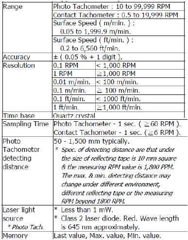
2 * Wide measuring range from 0.5 to 100,000 RPM, 0.1 RPM resolution for the measured value < 1000 RPM. * Microprocessor based circuit, crystal time base, high precision with 0.05% accuracy. * Memory with recall function, the last value, max., value, min. value will be stored into the memory automatically. * Patent patented. General function : * Super large LCD display. * No contact infrared temperature measurement via optional IR temp. probe. * RS 232 computer interface. * Optional data acquisition software and data logger software. * Microcomputer circuit, high performance. * Built-in low battery indicator. * Heavy duty & compact housing case. * Complete set with the hard carrying case. Specifications Vibration function:
3 Tachometer ( photo, contact ) function:

4 General function:
. 3. a) For the Acceleration measurement, press the \" Unit button \" ( 3-6, Fig.")
5 Front panel description Vibration measuring procedure Basic operation procedures 1. Plug in the " BNC plug " ( 3-12, Fig. 1 ) to the " BNC socket " ( 3-15, Fig. 1 ). 2. Power on the meter by pressing the " Power button " ( 3-2, Fig. 1 ). 3. a) For the Acceleration measurement, press the " Unit button " ( 3-6, Fig. 1 ) once until the display show the " ACC ", " m/s^2 ", " RMS " symbol or the " ACC ", " g ", " RMS " symbol. b) For the Velocity measurement, press the " Unit button " ( 3-6, Fig. 1 ) once until the display show the " VEL ", " mm/s " and " RMS " symbol or the " VEL ", " cm/s " and " RMS " symbol. c) For the Displacement measurement, press the " Unit button " ( 3-6, Fig. 1 ) once until the display show the " DISP(P-P) ", " mm " symbol. 4. If the surface material of measuring article is not the ferrous material, hold the vibration sensor by hand & touch the sensor to the surface of the measuring article, refer the Fig. 2 next page.
6 5. If the surface material of measuring article is the ferrous material, connect " Vibration sensor " ( 3-13, Fig. 1 ) with the " Magnetic base " ( 3-14 ), refer Fig. 3. Put the whole unit ( Vibration sensor & Magnetic base ) to the surface of measuring article, refer Fig. 4.
 at least 2 second continuously, the display unit can be changed from the Imperial unit to Metric unit or be changed from Metric unit to Imperial unit.")
7 Unit selection ( Imperial/Metric ) During the measurement, press the " Unit button " ( 3-6, Fig. 1 ) at least 2 second continuously, the display unit can be changed from the Imperial unit to Metric unit or be changed from Metric unit to Imperial unit. The Metric unit are : Acceleration measurement is m/s^2 or g. Velocity measurement is mm/s or cm/s. Displacement ( p-p ) measurement is mm. The Imperial unit are : Acceleration measurement is ft/s^2. Velocity measurement is inch/s. Displacement ( p-p ) measurement is inch. Function selection ( RMS/PEAK/MAX HOLD ) During the Acceleration, Velocity, Displacement measurement if press " Function/Send button " ( 3-5, Fig. 1 ) once can select the following function : 1. Function 1 ( RMS for ACC, VEL., p-p for DISP. ) : Function 1 is the basic operation function, for general operation select the function 1 typically. * If Acceleration function measure the " RMS " value, the display show " ACC " and " RMS " symbol. * If Velocity function measure the " RMS " value. the display show " VEL " and " RMS " symbol. * If Displacement functon measure the " p-p " ( peak to peak ) value, the display show " DISP ( p-p ) " symbol. The definition of " peak to peak ", please refer Fig Function 2 ( Peak, for ACC. and VEL, only ) : * If Acceleration function measure the " Peak " value, the display show " ACC " and " PEAK " symbol. * If Velocity function measure the " Peak " value. The display show " VEL " and " PEAK " symbol. The definition of " Peak ", refer Fig. 5.
8 3. Function 3 ( Max. hold, for ACC., VEL and DISP. ) : * If Acceleration function measure the " Max. peak " value with hold. the display show " ACC " and " PEAK MAX HOLD " symbol. The definition of " Max. peak hold " value, refer Fig. 5. * If the Velocity function measure the " Max. peak " value with hold the display show " VEL " and " PEAK MAX HOLD " symbol. The definition of " Max. peak hold " value, refer Fig. 5. * The Displacement function measure the max. " p-p " ( peak to peak ) value with hold, the display show "DISP ( p-p ) " and " MAX HOLD " symbol. The definition of " peak to peak ", please refer Fig. 6 * Max. hold reset : If intend rest the " MAX HOLD " value, just press the " Zero button " ( 3-3, Fig. 1 ) > 2 sec continuously, the display will return to zero and make the new max. hold value measurement again. Data hold During the measurement, push the " Hold button " ( 3-3, Fig. 1 ) will hold the measured value & the LCD will show " HOLD " symbol. Push the " Hold button " again to release the data hold function. Data Record ( Max., Min. reading ) The DATA RECORD function displays the maximum, minimum readings for the measurement of: Acceleration ( RMS ), Velocity ( RMS ) and Displacement ( p-p )
9 1. Press the " REC button " ( 3-4, Fig. 1 ) once to start the Data Record function. " REC " will be displayed. 2. With the " REC " symbol on the display : a) Press the " REC button " ( 3-4, Fig. 1 ) once, the "REC MAX. " symbol along with the maximum value will appear on the display. To delete the maximum value, just press the " Hold button " ( 3-3, Fig. 1 ) once. The display will show " REC " and execute the memory function continuously. b)press the " REC button" ( 3-4, Fig. 1 ) again, the REC MIN. " symbol along with the minimum value will appear on the display. To delete the minimum value, just press the" Hold button" ( 3-3, Fig. 1 ) once, then the display will show the " REC " symbol only and execute the memory function continuously. c) To exit the memory record function, just press the " REC button " for at least 2 seconds. The display will revert to the current reading. Zero adjustment procedure Due to drift of environment temperature value, battery power change or, meter used for a long time or other reasons. The display value may exist not zero value ( few digits ) in case of no signal into the " Vibration Sensor ". General speaking those not zero value will not effect the measurement typically. However if intend to make the precision measurement, the following zero adjustment procedures should be executed as : 1. Press the " Function buttion " ( 3-5, Fig. 1 ) to the " Acceleration " position. 2. No signal into the vibration sensor. 3. Press the " Zero button " ( 3-3, Fig. 1 ) continuously at least 2 second, the display will return to zero value with default. Data Logger The data logger function can save 1000-point data for the vibration function. The data logger procedures are as following : a) Press the " REC Button " ( 3-4, Fig. 1 ) once to start the Data Record function and there will be a " REC. " symbol on the display. b) Auto Data Logger ( Sampling time can select to 1, 2, 10, 30, 60, 600, 1800, 3600 seconds) Press the " Logger Button " ( 3-6, Fig. 1 ) once to start the Data Logger function. The " " symbol is flashed per the sampling time and the data will be saved into the memory circuit. Now the Date Logger function is executed. Manual Data Logger ( Sampling time set to 0 second ) Press the " Logger Button " ( 3-6, Fig. 1 ) once will save the data one time into the memory circuit. At the same time the " " symbol will be flashed.
10 Memory full: During execute the data logger function, if the display show " FULL ", it indicate the memory data already over 1000 no. and the memory is full. c) During the Data Logger function is executed, press the " Logger button " ( 3-6, Fig. 1 ) once will stop to execute the data logger function, the symbol " " will be disappeared. If press the " Logger Button " ( 3-6, Fig. 1 ) once again will continuous the Data Logger function. Remark : 1) If intend to change the data logger sampling time, please refer section 4-10/point 4, page 19. 2) If intend to know the space of balance data numbers into the memory IC, please refer section 4-10/point 5, page 19. 3) If intend to clear the saving data from the memory please refer section 4-10/point 6, page 20. How to send the data out from the meter 1. Before sending data out from the meter, exit the "Hold function " and the " Record " function. 2. Press the " Send Button " ( 3-5, Fig. 1 ) at least 2 seconds until display show " r-232 ", then release the button. 3. Push the " Send Button " ( 3-5, Fig. 1 ) once, display will count down, at the same the storage data logger data will send out the meter from the " RS-232 Output Terminal " ( 3-19, Fig. 1 ). 4. If intend load the data to the computer, it should connect the RS232 cable ( optional, model : UPCB-02) or USB cable ( optional, model : USB-01 ) and apply the Data Logger software ( optional, Model : SW-DL2005 ). Auto power off The meter is default to auto power off. If the user intend to disable the " Auto Power off " function, refer the section 4-10/point 3, page 18. Note : During execute the record function, the auto power function will disable too. Advanced setting procedure 1. Power off the meter, first use the finger to press the the " Hold button " ( 3-3, Fig. 1 ) continuously, then press the " Power button " ( 3-2, Fig. 1 ) once. Release the finger from " Hold button ". 2. One by one to press the " Hold button " ( 3-3, Fig. 1 ) once a while to select the five four function and display will show flashing text with as : OFF... Auto power On/Off management SEC... Change the data logger sampling time Cnt... To show the balance data numbers in the memory CLr... Clear the existing saving data from the memory ESC... Escape the advanced setting function
11 3. Auto power On/Off a. Use the " Hold button " to select the main function to " OFF ". b. Press the " Function button " ( 3-5, Fig. 1) or " Unit button " ( 3-6, Fig. 1) to select " 1 " or " 0 ". * If the display value show " 0 ", it will disable the Auto Power Off function. * If the display value show " 1 ", it will execute the Auto PowerOff function. c. After select the desiring value ( 1 or 0 ), press the " Enter button " ( 3-4, Fig. 1 ) to save the data with default. 4. Change the data logger sampling time a. Use the " Hold Button " to select the main function to " SEC ". b. Press the " Function button " ( 3-5, Fig. 1) or " Unit button " ( 3-6, Fig. 1) to select the data logger sampling time to 0, 1, 2, 10, 30, 60, 600, 1800, 3600 seconds. c. After the sampling time value is determined, press the " Enter button " ( 3-4, Fig. 1 ) to save the sampling time with default. 5. To show the balance data numbers in the memory Use the " Hold button " to select the main function to " Cnt ". In the same time display will show the balance data point that exist into the memory ( allow memorize data no. ). 6. Clear the existing saving data from the memory a. Use the " Hold button " to select the main function to " CLr ". b. Press the " Function button " ( 3-5, Fig. 1) or " Unit button " ( 3-6, Fig. 1) to select " 1 " or " 0 ". * If the display value show " 0 ", it will be not to clear the memory. * If the display value show " 1 " will execute the memory clear function.. c. After select the desiring value ( 1 or 0 ), press the "Enter button " ( 3-4, Fig. 1 ) to save the data with default. 7. ESC a. Use the " Hold button " to select the main function to " ESC ". b. Press the " ESC button " ( 3-3, Fig. 1 ) will escape the above advanced setting function. Tachometer measuring procedure Change the function 1. Press the " Operation Button " ( 3-7, Fig. 1 ) continuously an not release the finger from the button. 2. Press " Function Button " ( 3-5, Fig. 1 ) momentarily in sequence, the function will change to
 the function to \" Photo RPM \", refer chapter 5-1, page 20, 21. 2. Apply a \" Reflecting Mark \" to the object being measured.")
12 Note : * After the function be selected, release the buttons, the function will saved into the meter even turn off the meter. * Turn on the meter again, the existing select function will present. Photo RPM measurement 1. Select ( default ) the function to " Photo RPM ", refer chapter 5-1, page 20, Apply a " Reflecting Mark " to the object being measured. Press the " Operation button " ( 3-7, Fig. 1 ) continuously and align the " Laser Light Beam " ( 3-16, Fig. 1) with the applied target. Verify that the LCD " Monitor Indicator " ( ) lights when the target pass through the light beam. Measuring consideration : If the measured RPM values is very low ( for example less than 50 RPM ), recommend to attach more " Reflecting Marks " average to the object. It will get the real RPM with high resolution, precisely & fast sampling time when divided the reading values by the no. of the " Marks ". Contact RPM measurement 1. Select ( default ) the function to " Contact RPM ", refer chapter 5-1, page 20, Press the " Operation Button " ( 3-7, Fig. 1 ) & lightly pressing the " RPM Adapter " ( 3-9, Fig. 1 ) against the center hole on the hole of the measured rotating axis. Release the " Measuring Button " when the reading stabilizes ( approx. 2 sec. ). Surface Speed Measurement 1. Select ( default ) the function to surface speed " m/min " or " ft/min ", refer chapter 5-1, page Press the " Operation button " ( 3-7, Fig. 1 ) and simply attaching the " Surface Speed Wheel " ( 3-8, Fig. 1 ) to the detector. Release the " Power Button " when the reading stabilizes ( approx. 2 sec. ). Memory recall 1. The readout of " last value ", " max. value " & " min. value " can be obtained immediately & memorized into the circuit automatically after turning off the " Operation Button
13 " ( 3-7, Fig. 1 ) 2. When finish the measuring procedures ( after release the operation button ), the memorized values can be displayed on the LCD display whenever : a. First push the " REC button " ( 3-4, Fig. 1 ) - To display the last value ( " LA " and " the last value " will be displayed alternately ). b. Second, push the " REC button " again - To display the maximum value ( " UP " and " the max. value " will be displayed alternately). c. Third, push the " REC button " again - To display the minimum value ( " dn " and " the min. value " will be displayed alternately ). IR (Infrared) temperature measuring procedure 1. Power off the meter. 2. Prepare the IR Temp. probe ( optional, IR-962 ), connect the cable plug of IR Temp. probe into the " IR probe input socket " ( 3-18, Fig. 1 ). 3. Power on the meter. 4. Power on the IR Temp. probe. RS232 PC serial interface The instrument has RS232 PC serial interface via a 3.5 mm terminal ( 3-19, Fig. 1 ). The data output is a 16 digit stream which can be utilized for user's specific application. A RS232 lead with the following connection will be required to link the instrument with the PC serial port. The 16 digits data stream will be displayed in the following format : Each digit indicates the following status :

14 RS232 setting: Battery replacement 1. When the left corner of LCD display show " ",it is necessary to replace the battery. However, in-spec measurement may still be made for several hours after low battery indicator appears before the instrument become inaccurate. 2. Open the " Battery Cover " ( 3-20, Fig. 1 ) away from the instrument and remove the battery. 3. Install 1.5 V battery x 4 PCs ( UN-3, AA, Alkaline or heavy duty ) and replace the cover.
 are")
15 Operational accessories Classification ranges For the valuation of machines and equipment in the ISO 2372 and VDI 2056, four different kinds of machine groups with four classification ranges and their limits for vibration severity ( mm/s ) are determined.
16 The classifications for each machine group are specified as follows : Small machines, especially production electrical motors of up to 15 KW ( Group K ) Medium sized machines, especially electrical motors with 15 up to 75 KW output, without special foundations ( Group M ) Large machines on heavy foundations ( Group G ) Largest machines and turbo machines with a special foundations ( Group T ). Sensitivity relative table according to ISO 2954
200 us/2 ms/20 ms/200 ms, TDS ( PPM ) Real time data logger, Data logger no., RS232 CONDUCTIVITY METER Model : YK-2005CD
 Real time data logger, Data logger no., RS232 CONDUCTIVITY METER Model : YK-2005CD") 200 us/2 ms/20 ms/200 ms, TDS ( PPM ) Real time data logger, 16000 Data logger no., RS232 CONDUCTIVITY METER Model : YK-2005CD TABLE OF CONTENTS 1. FEATURES...1 2. SPECIFICATIONS... 2 2-1 General Specifications...2
200 us/2 ms/20 ms/200 ms, TDS ( PPM ) Real time data logger, 16000 Data logger no., RS232 CONDUCTIVITY METER Model : YK-2005CD TABLE OF CONTENTS 1. FEATURES...1 2. SPECIFICATIONS... 2 2-1 General Specifications...2
3 AXIS RF ELECTROMAGNETIC FIELD METER
 50 MHz to 3 GHz Radio Frequency Radiation Meters Electromagnetic Field strength measurement 3 AXIS RF ELECTROMAGNETIC FIELD METER Model : EMF-819 Your purchase of this RF EMF METER marks a step forward
PH METER OPERATION MANUAL. Model : PH-208
 PH METER Model : PH-208 Your purchase of this PH METER marks a step forward for you into the field of precision measurement. Although this PH METER is a complex and delicate instrument, its durable structure
ph, ORP, CD, TDS, DO, SALT METER
 ph, ORP, CD, TDS, DO, SALT METER Model : YK-2001PHA Your purchase of this ph, ORP, CD, TDS, DO, SALT METER marks a step forward for you into the field of precision measurement. Although this meter a complex
PH/ORP, DO CD/TDS METER Model : YK-2005WA
 Real time data logger PH/ORP, DO CD/TDS METER Model : YK-2005WA Your purchase of this PH/ORP, DO, CD/TDS METER marks a step forward for you into the field of precision measurement. Although this METER
2.7 GHz FREQUENCY COUNTER with TCXO
 2.7 GHz FREQUENCY COUNTER with TCXO TABLE OF CONTENTS 1. FEATURES... 1 2. SPECIFICATIONS... 1 2-1 General Specifications... 1 2-2 Table for Resolution & Sampling Time... 3 3. FRONT PANEL DESCRIPTION...4
DIGITAL OXYGEN METER. Model : DO-5510
 DIGITAL OXYGEN METER Model : DO-5510 ATTENTION : Fill the Probe's Electrolyte at first. Intend to keep the DO probe under the best condition, when user receive the DIGITAL OXYGEN METER along the PROBE,
CONDUCTIVITY/ TDS METER + PH meter. Model : DCT2001
 CONDUCTIVITY/ TDS METER + PH meter Model : DCT2001 TABLE OF CONTENTS 1. FEATURES... 1 2. SPECIFICATIONS... 2 2-1 General Specifications...2 2-2. Conductivity/TDS/Temp. specifications...3 a. Conductivity...
10 Amperes max. test current Micro-Ohm Meter Model : MO-2014 OPERATION MANUAL
 10 Amperes max. test current Micro-Ohm Meter Model : MO-2014 Your purchase of this Micro-Ohm METER marks a step forward for you into the field of p r e c i s i o n measurement. Although this Micro-Ohm
Mini Environmental Quality Meter
 Mini Environmental Quality Meter 850070 Instruction Manual SPER SCIENTIFIC LTD. TABLE OF CONTENTS I. INTRODUCTION... 2 II. PANEL DESCRIPTION... 3 III. OPERATING INSTRUCTIONS... 4 A. MEASUREMENT PROCEDURES...
ACA LEAKAGE TESTER OPERATION MANUAL. auto range, true rms. Model : DL-9954
 auto range, true rms ACA LEAKAGE TESTER Model : DL-9954 Your purchase of this ACA LEAKAGE TESTER marks a step forward for you into the field of precision measurement. Although this ACA LEAKAGE TESTER is
multi-function + auto-range, CATIII 1000V ACV/DCV/OHMS/4 to 4000 M ohm, 100V, 250V, 500V, 1000V INSULATION TESTER
 multi-function + auto-range, CATIII 1000V ACV/DCV/OHMS/4 to 4000 M ohm, 100V, 250V, 500V, 1000V INSULATION TESTER Model : DI-6400 Your purchase of this INSULATION TESTER marks a step forward for you into
User's Guide. Heavy Duty CFM Thermo-Anemometer. Model Washington Street Melrose, MA Phone Toll Free
 User's Guide 99 Washington Street Melrose, MA 02176 Phone 781-665-1400 Toll Free 1-800-517-8431 Visit us at www.testequipmentdepot.com Heavy Duty CFM Thermo-Anemometer Model 407113 above is inclusive and
POWER ANALYZER OPERATION MANUAL. Model : DW-6090A
 POWER ANALYZER Model : DW-6090A Your purchase of this POWER ANALYZER marks a step forward for you into the field of precision measurement. Although this POWER ANALYZER is a complex and delicate instrument,
HUMIDITY/TEMP. CONTROLLER/MONITOR
 HUMIDITY/TEMP. CONTROLLER/MONITOR Model : PHT-3109 Your purchase of this HUMIDITY/TEMP. CONTROLLER, MONITOR marks a step forward for you into the field of precision measurement. Although this METER is
LCR METER OPERATION MANUAL. Model : LCR Hz 120 Hz 1 KHz 10 KHz 100 KHz, Precision
 100 Hz 120 Hz 1 KHz 10 KHz 100 KHz, Precision LCR METER Model : LCR-9183 Your purchase of this LCR METER marks a step forward for you into the field of precision measurement. Although this LCR METER is
SOUND LEVEL METER OPERATION MANUAL. Model : SL Your purchase of this
 SOUND LEVEL METER Model : SL-4011 Your purchase of this SOUND LEVEL METER marks a step forward for you into the field of precision measurement. Although this METER is a complex and delicate instrument,
with Temperature measurement ANEMOMETER Model : AM-4202
 with Temperature measurement ANEMOMETER Model : AM-4202 Your purchase of this ANEMOMETER THERMOMETER marks a step forward for you into the field of precision measurement. Although this METER is a complex
Heavy Duty CFM-CMM Thermo-Anemometer With built-in non-contact IR Thermometer and Laser Pointer Model HD300
 User Guide Heavy Duty CFM-CMM Thermo-Anemometer With built-in non-contact IR Thermometer and Laser Pointer Model HD300 Introduction Congratulations on your purchase of the Extech HD300 CFM Thermo-Anemometer.
True RMS. AUTO RANGE MULTIMETER CAT III-1000 V category, Auto range, REL, Capacitance Hz, Duty, ACV, ACA, DCV, DCA, Ohms
 True RMS AUTO RANGE MULTIMETER CAT III-1000 V category, Auto range, REL, Capacitance Hz, Duty, ACV, ACA, DCV, DCA, Ohms Caution Symbol Caution : * Risk of electric shock! Caution : * Do not apply the overload
Caution Symbol. AUTO RANGE MULTIMETER CAT III-1000 V category, Auto range, Peak hold Bar graph display, Max/Min, REL, Cap.
 Caution Symbol AUTO RANGE MULTIMETER CAT III-1000 V category, Auto range, Peak hold Bar graph display, Max/Min, REL, Cap., Hz, RS232, Caution : * Risk of electric shock! Caution : * Do not apply the overload
User Guide. Heavy Duty Psychrometer + IR Thermometer. Model HD550
 User Guide Heavy Duty Psychrometer + IR Thermometer Model HD550 Introduction Congratulations on your purchase of the Extech HD550 Psychrometer. This handheld meter measures and displays Air Temperature,
2000 A DCA/ACA CLAMP + DMM,
 2000 A DCA/ACA CLAMP + DMM, true rms DCA/ACA CLAMP METER Model : CM-9930 Your purchase of this DCA/ACA CLAMP METER marks a step forward for you into the field of precision measurement. Although this CLAMP
RS232 CONTROLLER/MONITOR
 RS232 CONTROLLER/MONITOR Model : PRS-2321 Your purchase of this RS232 CONTROLLER, MONITOR marks a step forward for you into the field of precision measurement. Although this RS232 CONTROLLER MONITOR is
A4900 Vibrio M pocket guide
 A4900 Vibrio M pocket guide A4900 Vibrio M pocket guide Basic information 4 Switch on/off 5 Basic control 6 Basic menu 7 Measurement screens 8-9 Saving data from measurement screen 10 Light 11 Memory -
Professional Dual-Laser Infrared Thermometer with 50:1 Distance-to-Sight Ratio, Data Logging, USB Output, Single Type K Input, and Temperature Alarm
 User Manual 99 Washington Street Melrose, MA 02176 Phone 781-665-1400 Toll Free 1-800-517-8431 Visit us at www.testequipmentdepot.com Professional Dual-Laser Infrared Thermometer with 50:1 Distance-to-Sight
2,000 counts, 200 Amp ACA/DCA, 600 V ACV/DCV, True RMS, OHMS, Continuity, Hold, Peak Hold FORK CURRENT TESTER. Model : FT-9950
 2,000 counts, 200 Amp ACA/DCA, 600 V ACV/DCV, True RMS, OHMS, Continuity, Hold, Peak Hold FORK CURRENT TESTER Model : FT-9950 Caution Symbol Caution : * Risk of electric shock! Caution : * Do not apply
Psychrometer With IR DT-8896 Operation Manual
 Psychrometer With IR DT-8896 Operation Manual PROBE %RH/TEMP MAX MIN WB DP HOLD IRT C F MAX IR K TEMP HOLD MIN INTRODUCTION Thank you for purchase of the DT-8896 Psychrometer with IR Thermometer. This
metro B6012 VIBRATIONS SIMPLIFIED... Product brochure Easiest portable vibration analyzer and balancer TECHNOLOGIES PVT. LTD.
 metro B6012 VIBRATIONS SIMPLIFIED... Product brochure Easiest portable vibration analyzer and balancer TECHNOLOGIES PVT. LTD. Product brocure 1 is reliable, fast and easiest to use tool designed for routine
FAG Detector II the mobile among data collectors. Technical Product Information
 FAG II the mobile among data collectors Technical Product Information Application Condition-based maintenance Principle Application The FAG II is a vibration measuring device and data collector rolled
DIGITAL DUAL DISPLAY AC/DC CLAMP METER MODEL-860A OPERATION MANUAL
 DIGITAL DUAL DISPLAY AC/DC CLAMP METER MODEL-860A OPERATION MANUAL DIGITAL DUAL DISPLAY AC/DC CLAMP METER MODEL-860A TABLE OF CONTENTS TITLE PAGE Safety Information Safety Symbols... 1 Meter Description...
APPA 300 Series. The Most User-Friendly High Performance Multimeter
 APPA 300 Series The Most User-Friendly High Performance Multimeter Throw Away the Manual... So Easy, So Simple Straight Forward... For basic application, simply to operate these keys... "LIGHT" "BAR" "DIGIT"
0.01kV (0 to ±0.99 kv)
") Handheld Electrostatic Meter Series IZH10 Easy-to-use handheld electrostatic meter Rated charge amount range: ±20.0 kv Minimum display unit: 0.1kV (±1.0 to ±20.0 kv) Check the current situation before
Handheld Electrostatic Meter Series IZH10 Easy-to-use handheld electrostatic meter Rated charge amount range: ±20.0 kv Minimum display unit: 0.1kV (±1.0 to ±20.0 kv) Check the current situation before
500C Advanced Training Outline
 500C Advanced Training Outline 1. Opacity Basics 2. Math used with the 500C 3. Trasmissometer Evolution Single Pass 1. Simple 2. Ambient light interference 3. Difficult to verify calibration Double Pass
Printing Humidity/Temperature Meter
 Printing Humidity/Temperature Meter INSTRUCTION MANUAL I. SAFETY INFORMATION Read the following safety information carefully before attempting to operate or service the meter. Use the meter only as specified
Model. Instruction Manual. Digital ph Pen. reedinstruments. REED Instruments
 Model Instruction Manual 8689 Digital ph Pen reedinstruments com Table of Contents Features... 3 Specifications... 3 Instrument Description... 4 Operating Instructions...4-10 Data Hold... 5 Auto Power
MS6231 DIGITAL ENGINE ANALYZER OPERATOR S MANUAL CONTENTS CONTENTS
 CONTENTS MS6231 DIGITAL ENGINE ANALYZER OPERATOR S MANUAL CONTENTS 1. SAFETY INFORMATION 1 1.1 PRELIMINARY 2 1.2 DURING USE 3 1.3 SYMBOLS 5 1.4 MAINTENANCE 6 2. DESCRIPTION 8 2.1 NAMES OF COMPONENTS 9
Combination Photo-Tachometer Stroboscope Model
 99 Washington Street Melrose, MA 02176 Phone 781-665-1400 Toll Free 1-800-517-8431 Visit us at www.testequipmentdepot.com Back to the Extech 461825 Product Page User s Guide Combination Photo-Tachometer
Model φ/1φ Power Clamp-on Meter
 User's Manual 99 Washington Street Melrose, MA 02176 Phone 781-665-1400 Toll Free 1-800-517-8431 Visit us at www.testequipmentdepot.com Back to the Extech 382075 Product Page Model 382075 3φ/1φ Power Clamp-on
SPEEDBOX Technical Datasheet
 SPEEDBOX Technical Datasheet Race Technology Limited, 2008 Version 1.1 1. Introduction... 3 1.1. Product Overview... 3 1.2. Applications... 3 1.3. Standard Features... 3 2. Port / Connector details...
Vibration Meter Operation Manual REV. A DATE:
 Vibration Meter Operation Manual 65-233-209 REV. A DATE: 2001-09 Hanson Research Corporation 9810 Variel Avenue Chatsworth, CA 91311 USA (800) 821-8165 (818) 882-7266 FAX (818) 882-9470 www.hansonresearch.com
User's Manual. Model f/1f Power Clamp-on Meter
 User's Manual Model 382075 3f/1f Power Clamp-on Meter Introduction Congratulations on your purchase of the Extech Model 382075 Auto Range Power Clamp-On Meter. Careful use of this device, will provide
The new generation More comfortable even faster more precise SmartBalancer2 Perfect field balancing made easy
 The new generation More comfortable even faster more precise SmartBalancer2 Perfect field balancing made easy RP 1141e A new dimension in comfort, speed and precision The reliability of your machines and
PVA Sensor Specifications
 Position, Velocity, and Acceleration Sensors 24.1 Sections 8.2-8.5 Position, Velocity, and Acceleration (PVA) Sensors PVA Sensor Specifications Good website to start your search for sensor specifications:
1510A PRECISION SIGNAL SIMULATOR
 A worldwide leader in precision measurement solutions Portable signal source for calibrating electronic equipment and machinery monitoring systems. 1510A PRECISION SIGNAL SIMULATOR Voltage Signals Charge
INSTRUCTION MANUAL IMPORTANT: Please read this manual in its entirety prior to using this device!
 INSTRUCTION MANUAL IMPORTANT: Please read this manual in its entirety prior to using this device! DIGITAL NIGHT VISION 1. Your night vision viewer operates with batteries. Unlike a daylight binocular,
Lab 1: Testing and Measurement on the r-one
 Lab 1: Testing and Measurement on the r-one Note: This lab is not graded. However, we will discuss the results in class, and think just how embarrassing it will be for me to call on you and you don t have
MAGNETIC FIELD MEASURING
 LIST- MAGNETIK MAGNETIC FIELD MEASURING www.list-magnetik.de INFORMATION Magnetic Field Measuring Magnetic fields are invisible. The magnetism of a workpiece can only be recognized by the effect on other
Dynatel. 2273M Cable/Pipe and Fault Locators 2273M-iD Cable/Pipe/Fault and Marker Locators with id Read/Write
 3 Dynatel 2273M Cable/Pipe and Fault Locators 2273M-iD Cable/Pipe/Fault and Marker Locators with id Read/Write Designed to be more accurate, faster and more integrated than any other locator on the market,
User s Guide. Combination Photo-Tachometer Stroboscope Model
 User s Guide Combination Photo-Tachometer Stroboscope Model 461825 Introduction Congratulations on your purchase of Extech s Combination Photo- Tachometer/Stroboscope. This professional meter, with proper
Multifunction Digital
 MS2009A Multifunction Digital Clamp Meter User Manual 200/600 OFF 2/20 NCV SEL MAX V RAN HOLD OFF MS2009A AC CLAMP METER AUTO MAX C F kmω μmva CONTENTS Safety requirements...1 Safety signs...1 Notes...1
T 1000 PLUS. Secondary Injection Relay Test Set. Designed for testing relays and transducers
 Secondary Injection Relay Test Set Designed for testing relays and transducers Microprocessor controlled With phase angle shifter Frequency generator Test results and settings are saved into local memory
QUICK START GUIDE. AStrO. Ver Toll Free : 1 (877) Visit :
 Visit :") QUICK START GUIDE AStrO Ver.10.309 Toll Free : 1 (877) 462-7296 Visit : 1 Thank you for purchasing the latest in data acquisition technology, the AStrO. We hope that it surpasses your expectations. This
QUICK START GUIDE AStrO Ver.10.309 Toll Free : 1 (877) 462-7296 Visit : 1 Thank you for purchasing the latest in data acquisition technology, the AStrO. We hope that it surpasses your expectations. This
6000 W, 2450 MHz Microwave Generator GMP 60K SM 56T400 FST 3 IR
 6000 W, 2450 MHz Microwave Generator GMP 60K SM 56T400 FST 3 IR Power supply It is based upon the latest switch mode power supply technology, offering size reduction (smallest 6 kw available on the market,
RAGU 81D DIGITAL MULTIMETER OPERATION MANUAL
 RAGU 81D DIGITAL MULTIMETER OPERATION MANUAL Contents I. General...- 1 - Ⅱ. Open-package Inspection...- 2 - III. Safety Considerations... - 3 - IV.Instrument Panel & Button Function Description...- 9 -
LASER PHOTO TACHOMETER
 LASER PHOTO TACHOMETER Model : DT-2234BL Your purchase of this LASER PHOTO TACHOMETER marks a step forward for you into the field of precision measurement. Although this TACHOMETER is a complex and delicate
TD 1000 PLUS. Secondary Injection Relay Test Set. Designed for testing relays and transducers
 Secondary Injection Relay Test Set Designed for testing relays and transducers Two current outputs to test differential relays Convertible current and voltage generator With phase angle shifter Frequency
Model R7900. Instruction Manual. Ultrasonic Thickness Gauge. reedinstruments. www. com
 Model R7900 Ultrasonic Thickness Gauge Instruction Manual reedinstruments com Table of Contents Features... 3 Specifications...4-5 Instrument Description... 6 Operating Instructions...7-10 Adjusting the
EM420A/420B DIGITAL MULTIMETER OWNERS MANUAL Read this owners manual thoroughly before use
 http://www.all-sun.com EM420A/420B DIGITAL MULTIMETER OWNERS MANUAL V Read this owners manual thoroughly before use WARRANTY This instrument is warranted to be free from defects in material and workmanship
Dawson DDM230C. True RMS Multimeter with Bar Graph Display User s Manual
 Dawson DDM230C True RMS Multimeter with Bar Graph Display User s Manual Table of Contents LIMITED WARRANTY AND LIMITATION OF LIABILITY... 3 Out of the Box... 3 Accessories... 4 Safety Information... 4
Digital MultiMeter - Make your job efficiency User Instruction Manual
 Digital MultiMeter - Make your job efficiency User Instruction Manual Main Fields of Application: Process industries, Metallurgy, Power generation, Research, Laboratories, Maintenance, After sales service,
Operating Manual MRL-101
 Operating Manual MRL-101 Maintenance and Safety While the instrument is operating, be careful not to expose your eyes to the laser beam. Direct exposure to a laser beam for a long time may be hazardous
Model UT233 OPERATING MANUAL
 Model UT233 OPERATING MANUAL TABLE OF CONTENTS TITLE PAGE Overview Unpacking Inspection Safety Information Rules For Safe Operation International Electrical Symbols The Meter Structure A. The Meter Front
EM5. Multifunctional Environmental Meter. Sealed Unit Parts Co., Inc. User Manual
 EM5 Multifunctional Environmental Meter User Manual Sealed Unit Parts Co., Inc. Contents Description Pages 1. Safety information 1 2. Description 2 3. Specifications 6 4. Operating instruction 8 5. Accessories
INTRODUCTION CHAPTER 1
 TABLE OF CONTENTS Introduction... 3 Package Contents... 5 Design... 7 Key Functions... 9 Grain Species and Measuring Ranges....11 First Steps...13 Measurement...15 Modification...19 Setup...21 Replacing
USER'S MANUAL DMR-4350
 USER'S MANUAL DIGITAL MULTIMETER DMR-4350 CIRCUIT-TEST ELECTRONICS www.circuittest.com TABLE OF CONTENTS SAFETY Safety Information...................................... 2 Safety Symbols........................................
USER'S MANUAL DMR-4300
 USER'S MANUAL DIGITAL MULTIMETER DMR-4300 CIRCUIT-TEST ELECTRONICS www.circuittest.com TABLE OF CONTENTS SAFETY Safety Information...................................... 2 Safety Symbols........................................
USER MANUAL. Laser Distance Meter MODELS DT40M, DT60M, and DT100M
 USER MANUAL Laser Distance Meter MODELS DT40M, DT60M, and DT100M Contents Introduction... 3 Safety Instructions... 3 Descriptions... 4 Measurement Preparation... 6 Programming Menu... 8 Distance Measurements...
Fluke 1740 Series. Three-Phase Power Quality Loggers Memobox. Assess power quality and conduct long-term studies with ease
 Fluke 1740 Series Three-Phase Power Quality Loggers Memobox Technical Data Assess power quality and conduct long-term studies with ease Compact and rugged, the Fluke 1740 Series three-phase power quality
MAGNETIC FIELD METER Operator s Manual
 Edition 4.4 September 2011 MAGNETIC FIELD METER 3000 Operator s Manual The MFM 3000 is a professional magnetic field instrument To make the best use of the instrument we recommend that you read this manual
Wireless Console User Guide Instructions for use with the Universal Trainer and Speed/Cadence Sensor
 Wireless Console User Guide Instructions for use with the Universal Trainer and Speed/Cadence Sensor A. Parts list ⓵ 1. Wireless Console (WC) 2. Batteries 3. Speed/Cadence Sensor (SCS) 4. Crank arm magnet
AA-35 ZOOM. RigExpert. User s manual. Antenna and cable analyzer
 AA-35 ZOOM Antenna and cable analyzer RigExpert User s manual . Table of contents Introduction Operating the AA-35 ZOOM First time use Main menu Multifunctional keys Connecting to your antenna SWR chart
MS8250D DUAL DISPLAY DIGITAL MULTIMETER User s Manual
 DUAL DISPLAY DIGITAL MULTIMETER User s Manual MS8250D 1. Safety Information Warning Use caution and follow all safety guidelines to prevent electric shock or damage to the meter. Please ready carefully
4830B accelerometer simulator Product overview
 4830B accelerometer simulator Product overview 2015 Product overview Simulates the electrical output signals generated by common measurement transducers (vibration, pressure, acoustics, etc.) Portable,
USER MANUAL ENGLISH 1450 COIN COUNTER & SORTER
 USER MANUAL ENGLISH 1450 COIN COUNTER & SORTER INTRODUCTION ENGLISH Thank you for purchasing the Safescan 1450 coin counter and sorter. For proper use and maintenance, we advise to read this user manual
Momentum and Impulse. Objective. Theory. Investigate the relationship between impulse and momentum.
 [For International Campus Lab ONLY] Objective Investigate the relationship between impulse and momentum. Theory ----------------------------- Reference -------------------------- Young & Freedman, University
Vibration Calibrator
 SPECTRUM INSTRUMENTS LTD. USER S MANUAL For the SVS-3 Vibration Calibrator The information provided in this Manual is believed to be reliable. However, Spectrum Instruments assumes no responsibility for
Frequency Calibrator with Totalizer
 Frequency Calibrator with Totalizer Model 942 0.001% accuracy Locked to high stability crystal Six real world ranges 1 to 20000 counts-per-hour to 2000.0 counts-per-minute 0.01 to 999.99 Hz to 9999.9 Hz
Laser Distance Finder Extech DT500
 User Guide Laser Distance Finder Extech DT500 Introduction Congratulations on your purchase of the Extech Model DT500 Laser Distance Finder. This meter measures Distance up to 70m (230 ) and calculates
2 / 3 axis joystick with power outputs (PWM)
") DESCRIPTION JP is a 2 or 3 axis electronic joystick with power outputs, able to directly control up to 6 proportional solenoid valves with PWM outputs proportional to joystick movements. Joystick movements
DESCRIPTION JP is a 2 or 3 axis electronic joystick with power outputs, able to directly control up to 6 proportional solenoid valves with PWM outputs proportional to joystick movements. Joystick movements
MT3500 Hand-Held Engine Analyzer Safety Operation Regulations
 MT3500 Hand-Held Engine Analyzer Safety Operation Regulations - 1 - Chapter One Introduction A. Notice of Usage: MT3500 Hand-Held Engine Analyzer must be operated by trained professionals, who must know
10.00 (1/2) PAC series
 PAC series") Clamp-on AC/DC current probes PAC Series The is a range of professional AC/DC clamp-on current probes designed to meet the very latest in safety and performance standards. There are two different jaw designs
Clamp-on AC/DC current probes PAC Series The is a range of professional AC/DC clamp-on current probes designed to meet the very latest in safety and performance standards. There are two different jaw designs
MAGNETIC FIELD METER Operator s Manual
 Edition 3.1 2009-09-03 MAGNETIC FIELD METER 2000 Operator s Manual The MFM 2000 is a professional magnetic field instrument To make the best use of the instrument we recommend that you read this manual
PRODUCTS AND ACCESSORIES
 75-0011 MODEL: GS-101 : THE GS-101 LONG RANGE PASSIVE INFRARED SENSOR (PIRS) IS AN INTRUSION DETECTOR WHICH RESPONDS TO INFRARED ENERGY RADIATED BY PEDESTRIANS OR VEHICLES WITHIN ITS FIELD OF VIEW. USEFUL
OPERATOR S INSTRUCTION MANUAL
 OPERATOR S INSTRUCTION MANUAL AUTO-RANGE DUAL DISPLAY CONFORMED IEC1010 DIGITAL MULTIMETER CONTENTS PAGE SAFETY INFORMATION..... DESCRIPTION.. OPERATING INSTRUCTION.. SPECIFICATIONS.... ACCESSORIES. BATTERY
FAG Detector III The solution for monitoring and balancing. Technical Product Information
 FAG III The solution for monitoring and balancing Technical Product Information Principle Operation High functionality Simple handling The FAG III is a vibration measuring device, data collector and operational
Laser Distance Finder Extech DT500
 User Guide Laser Distance Finder Extech DT500 Introduction Congratulations on your purchase of the Extech Model DT500 Laser Distance Finder. This meter measures Distance up to 70m (230 ) and calculates
MS2109A AC/DC Clamp Meter. User Manual. Contents
 MS2109A AC/DC Clamp Meter User Manual Contents 1. Safety information 1 1.1 Preparation 1 1.2 Usage 1 1.3 Signs and Labels 2 1.4 Maintenance 2 2. Description 2 2.1 Part name 3 2.2 Switch and button description
ST-10 Expert. Horn Analyzer. for serial and parallel resonance Resonators. Bär. Operator Manual.
 Bär Elektronik Hauptstrasse 39 CH-8594 Güttingen 0041 71 695 12 83 Horn Analyzer ST-10 Expert for serial and parallel resonance Resonators Operator Manual Version 2.5 www.baer-elektronik.ch ndice 1.0 Controls
METALLOGRAPHY EQUIPMENT
 Fully matic Abrasive Cutting Machine - SERVOCUT 602 www.worldoftest.com/fully-automatic-abrasive-cutting-machine-servocut-602 Applications: Fully matic Abrasive Cutting Machine - SERVOCUT 602 is a fully
OWNER S MANUAL HH0308C. AUTO-RANGING DC/True RMS AC DIGITAL MULTIMETER
 OWNER S MANUAL HH0308C AUTO-RANGING DC/True RMS AC DIGITAL MULTIMETER IMPORTANT! Read and understand this manual before using the tester. Failure to understand and comply with safety rules and operating
Rotary tuning knob /Fine tuning Clarify. Music/Normal /News Tone control SSB fine tune. Telescopic Antenna Earphones socket
 Control Locations Power/Sleep Power On/off/Alarm off/sleep function Display Switch between radio frequency and time while radio is power on Mode Mode set up (please see below mode button set up) Radio
Keysight U1231A/ U1232A/U1233A Handheld Multimeter. Quick Start Guide
 Keysight UA/ UA/UA Handheld Multimeter Quick Start Guide Contacting Keysight www.keysight.com/find/assist (worldwide contact information for repair and service) Safety and EMC Information This meter is
Micro Wizard Instructions
 How to install your Fast Track flashing light display timer model K1 with optional remote start switch (If you have ordered the Quick Mount or have a Best Track, disregard this section and refer to the
FIXTURLASER NXA Ultimate
 FIXTURLASER NXA Ultimate Welcome to our world. Since the very beginning in 1984, ACOEM AB has helped industries throughout the world to achieve more profitable and sustainable production. We have reached
Analog Technologies VC99. Multimeter FEATURES
 FEATURES LCD Display Max Display: 6000(3 6/7) Digits Automatic Polarity, Unit Symbol and 61 Section Analog Display Measurement Method: Double Integral A/D Conversion Sampling Rate: Approx.3 times/sec Over-Range
Infrared Thermometer Remote Temperature Measurement ( Non-Contact ) 1327 INSTRUCTION MANUAL
 1327 INSTRUCTION MANUAL") RS Infrared Thermometer Remote Temperature Measurement ( Non-Contact ) 1327 INSTRUCTION MANUAL TABLE OF CONTENTS TITLE PAGE INTRODUCTION...1 Ⅰ. SAFETY INFORMATION...1 Ⅱ. FEATURES...3 Ⅲ. SPECIFICATIONS...3
RS Infrared Thermometer Remote Temperature Measurement ( Non-Contact ) 1327 INSTRUCTION MANUAL TABLE OF CONTENTS TITLE PAGE INTRODUCTION...1 Ⅰ. SAFETY INFORMATION...1 Ⅱ. FEATURES...3 Ⅲ. SPECIFICATIONS...3
OPERATOR S INSTRUCTION MANUAL M-2625 AUTO RANGING DIGITAL MULTIMETER
 OPERATOR S INSTRUCTION MANUAL M-2625 AUTO RANGING DIGITAL MULTIMETER with Temperature Probe Copyright 2007 Elenco Electronics, Inc. Contents 1. Safety Information 3,4 2. Safety Symbols 5 3. Front Plate
Painting with Light Above: Flashlight Painting Right: Laser Painting
 Painting with Light Above: Flashlight Painting Right: Laser Painting Mr. Mac s Tech Ed Class For Canon XS Created Aug 2011 Vocabulary: Exposure Time is the amount of time the shutter is open which allows
Fluke 3540 FC Three-Phase Power Monitor
 Test Equipment Depot - 800.517.8431-99 Washington Street Melrose, MA 02176 - TestEquipmentDepot.com TECHNICAL DATA Fluke 3540 FC Three-Phase Power Monitor THREE-PHASE MONITORING AND STREAMING Monitor three-phase