2016 Vol.62 No. Power Semiconductors Contributing in Energy Management
|
|
|
- Dwain Johnston
- 6 years ago
- Views:
Transcription


1 4 216 Vol.62 No. Power Semiconductors Contributing in Energy Management
2 216 Vol.62 No. 4 Power Semiconductors Contributing in Energy Management Cover Photo (clockwise from the upper left): FUJI ELECTRIC REVIEW vol.62 no date of issue: December 3, 216 editor-in-chief and publisher editorial office EGUCHI Naoya Corporate R & D Headquarters Fuji Electric Co., Ltd. Gate City Ohsaki, East Tower, 11-2, Osaki 1-chome, Shinagawa-ku, Tokyo , Japan Fuji Electric Journal Editorial Office c/o Fuji Office & Life Service Co., Ltd. 1, Fujimachi, Hino-shi, Tokyo , Japan
3 Contents Power Semiconductors Contributing in Energy Management 1.2-kV SiC Trench MOSFET 218 TSUJI, Takashi IWAYA, Masanobu ONISHI, Yasuhiko All-SiC 2-in-1 Module 222 CHONABAYASHI, Mikiya OTOMO, Yoshinori KARASAWA, Tatsuya Enhanced Breakdown Voltage for All-SiC Modules 227 HINATA, Yuichiro TANIGUCHI, Katsumi HORI, Motohito Enhanced Thermal Resistance of Molding Resin Used for All-SiC 232 Modules NAKAMATA, Yuko TACHIOKA, Masaaki ICHIMURA, Yuji 7th-Generation X Series IGBT Module Dual XT 236 YOSHIDA, Kenichi YOSHIWATARI, Shinichi KAWABATA, Junya 7th-Generation X Series RC-IGBT Module for Industrial Applications 241 YAMANO, Akio TAKAHASHI, Misaki ICHIKAWA, Hiroaki 2nd-Generation Small IPM Series 246 TEZUKA, Shinichi SUZUKI, Yoshihisa SHIRAKAWA, Toru Speed Enhancement for the 3rd-Generation Direct Liquid Cooling 251 Power Modules for Automotive Applications with RC-IGBT KOGE, Takuma INOUE, Daisuke ADACHI, Shinichiro Functionality Enhancement of 3rd-Generation Direct Liquid Cooling 256 Power Modules for Automotive Applications Equipped with RC-IGBT SATO, Kenichiro ENOMOTO, Kazuo NAGAUNE, Fumio High-Side 2-in-1 IPS F5114H for Automobiles 261 MORISAWA, Yuka TOBISAKA, Hiroshi YASUDA, Yoshihiro 2nd-Generation SJ-MOSFET for Automotive Applications 265 Super J MOS S2A Series TABIRA, Keisuke NIIMURA, Yasushi MINAZAWA, Hiroshi Critical Mode PFC Control IC FA1A6N and LLC Current Resonant 269 Control IC FA6B2N for High-Efficiency Power Supplies SONOBE, Koji YAGUCHI, Yukihiro HOJO, Kota 2nd-Generation Low Loss SJ-MOSFET with Built-In Fast Diode 275 Super J MOS S2FD Series WATANABE, Sota SAKATA, Toshiaki YAMASHITA, Chiho New Products MICREX-SX Series Motion Controller SPH3D to 145-kV Compact Gas-Insulated Switchgear SDH Frozen Storage Container WALKOOL 286 FUJI ELECTRIC REVIEW vol.62 no.4 216

4 1.2-kV SiC Trench MOSFET TSUJI, Takashi * IWAYA, Masanobu * ONISHI, Yasuhiko * A B S T R A C T Fuji Electric has developed and released SiC planar gate MOSFETs. Excessive shrinkage of the cell pitch of planar MOSFETs leads to a high JFET resistance, which prevents them from achieving a low on-resistance close to the theoretical limit. To the contrary, the cell pitch of trench-gate MOSFETs can be shrunk without the increase of the JFET resistance. We have therefore developed a 1.2-kV SiC trench gate MOSFET. We have optimized the structures of the MOS channel and the JFET region, as well as reduced the cell pitch. Our trench-gate MOSFETs realize low switching loss, the increase of the threshold voltage 2.4 times, and the reduction of the on-state resistance by 48% compared with the conventional planar MOSFETs. 1. Introduction Fuji Electric contributes to a sound material-cycle society through variety of power electronics systems utilized for railcars, automobiles, power supplies and electric power systems. Power semiconductor devices, which are core components of power electronics systems, have been evolving from those of silicon (Si) to those of silicon carbide (SiC), which is one type of wide band gap semiconductors. In the voltage rating of 1.2 kv, Si insulated gate bipolar transistors (IGBTs) have been replaced by SiC metal-oxide-semiconductorfield-effect-transistors (MOSFETs), which show lower conduction losses and switching losses than those of Si-IGBTs, due to the lower drift layer resistance of approximately one-three hundredth of that of Si (1) and no minority carriers swept during switching. Fuji Electric has developed and released SiC planar gate MOSFETs and all-sic modules, in which SiC planar gate MOSFETs were mounted (2),(3). The all-sic modules have been incorporated into our highefficiency, compact and lightweight power conditioning sub-systems (PCSs) (4) and mega solar PCSs (5). This paper describes our recent development of 1.2-kV SiC trench gate MOSFETs. limit (6). An effective means of reducing MOS channel resistance is increasing cell density (refining), as well as improving the SiO 2/SiC interface. However, excessive refinement of conventional planar gate MOSFETs results in an increase in junction field-effect transistor (JFET) resistance (1). On the other hand, refinement of trench gate MOSFETs, which have the MOS channel oriented perpendicular to the surface, do not result in an increase in the JFET resistance, and as a result, onstate resistance can be reduced in proportion to refinement. The cross-sectional structure of our recently developed SiC trench gate MOSFETs and a photograph of the chip are shown in Fig. 1. The development was based on the following 3 points: (a) Improvement of the gate oxide reliability (b) Simultaneous establishment of a high threshold voltage and a low on-state resistance (c) Simultaneous establishment of a low on-state resistance and a high breakdown voltage In order to improve the reliability of the gate ox- p + n + Gate SiO 2 Source Source electrode n + p + 2. Design and Features of SiC Trench Gate MOSFETs Compared with Si, SiC has a higher interface state density at the interface between SiO 2 as the gate oxide and SiC, and the capturing of electrons more likely to occur. As a result, there is an increase in MOS channel resistance, and this prevents SiC MOSFETs from the reduction of on-state resistance to its theoretical * Electronic Devices Business Group, Fuji Electric Co., Ltd. p base p base p + n p + n p + Gate B C A C B n drift layer n + substrate Drain (a) Cross-sectional structure Fig.1 SiC trench gate MOSFET (b) Chip photograph 218
5 2. ide, it is necessary to relax the high electric field on the gate oxide at the bottom of the trench in the reverse biased mode. Therefore, we adopted a structure to cover the gate oxide at the bottom of trenches with p-wells (see A in Fig. 1). The device simulation shows that the electric field reaches a maximum at the bottom corner portion of the p-well at the bottom of the trench, and thus, we confirmed the relaxation of the electric field in the gate oxide (7). In order to establish a high threshold voltage and low on-state resistance simultaneously, we reduced the cell pitch and optimized the MOS channel length. As shown in Fig. 2, on-state resistance decreased in proportion as the shrinkage of the cell pitch. In order to maintain a high process capability of the process, the cell pitch was set to approximately one half of that of planar gate MOSFETs. As for the simultaneous establishment of a low onstate resistance and high breakdown voltage, we optimized the JFET regions (see C in Fig. 1), which were located in the areas between the p-wells at the bottom of the trench (see A in fig. 1) and those below the source contact (see B in Fig. 1). By making this optimization, we were able to determine multiple parameters by utilizing a device simulation (7). The relationship between the on-state resistance and breakdown voltage trade-off is shown in Fig. 3. This optimization of the JFET region enabled us to reduce on-state resistance by about 3%, while improving breakdown voltage by about 2%. 3. Characteristics 3.1 Static characteristics The static characteristics of the recently developed SiC trench gate MOSFETs are shown in Fig. 4. The drain current-drain voltage characteristics in the forward biased mode at device junction temperatures of 25 C and 175 C are shown in Fig. 4 (a). It shows the on-state voltages at the rated current of 1.3 V at 25 C and 2.3 V at 175 C, respectively. The drain currentdrain voltage characteristics in the reverse biased mode are shown in Fig. 4 (b). The breakdown voltages are 1.55 kv at 25 C and 1.61 kv at 175 C, respectively. These breakdown voltages are high enough for the devices in the voltage rating of 1.2-kV. Similar to the planar gate MOSFETs, the breakdown voltage increases in proportion as the rise in temperature. The temperature dependencies of the threshold voltage and on-state resistance are shown in Fig. 5. The threshold voltage reduces monotonically with the temperature rise within a range from 25 C to 2 C, and decreases by approximately 26% at 175 C com- issue: Power Semiconductors Contributing in Energy Management Ron A(a.u.) Cell pitch (a.u.) Fig.2 Cell pitch dependence of on-state resistance Ron A(a.u.) Before JFET region optimization Trade-off improvement After optimization 1.3 1, 1,2 1,4 1,6 1,8 Breakdown voltage (V) Fig.3 Relationship between on-state resistance and breakdown voltage trade-off C C Drain voltage V DS (V) (a) Drain current- drain voltage characteristics in the forward biased mode C 175 C , 1,5 2, Drain voltage V DSS (V) (b) Drain current- Drain voltage curves in the reverse biased mode Drain current IDS (a.u.) Drain current IDSS (a.u.) Fig.4 Static characteristics of SiC trench gate MOSFET 1.2-kV SiC Trench MOSFET 219
6 Ron A (a.u.) Temperature T j ( C) Fig.5 Temperature dependencies of threshold voltage and onstate resistance V bus SBD Gate resistance R g Inductive load L DUT Threshold voltage Vth (a.u.) pared with that of 25 C. The on-state resistance increases monotonically with the rise of temperature, and increases by approximately 57% at 175 C compared with that of 25 C. According to the dependence of the on-resistance on the temperature, the trench gate MOSFETs could suppress the thermal runaway in case of connecting multiple chips in parallel because temperature rise causes an increase of the on-state resistance and a decrease of the current in turn even when a current crowding occurs in a specified chip. It should be also denoted that the trench gate MOSFETs have successfully reduced the on-state resistance normalized by unit area by approximately 5% compared with the planar gate MOSFETs. The trench gate MOSFETs are expected to contribute to further reduction of the cost in overall systems in terms of the miniaturization of cooling components and the improvement of efficiency in modules and power electronics systems. 3.2 Switching characteristics The switching test circuit and the typical turn-on and turn-off waveforms are shown in Fig. 6. The turnon time, which is defined by the duration from the time of V GS= V until the time that drain current reaches 9% in the on state, is approximately 6 ns. The turnoff time, which is defined by the duration from the time that the gate voltage is 9% in the on state until the time the drain current reaches 1% in the on state, is approximately 75 ns. The gate resistance dependence of the switching V GS V DS I DS (a) Switching test circuit 5 ns/div Turn-on loss Eon (a.u.) 1..9 V bus = 6 V.8 25 C Planar gate.7 MOSFET Trench gate MOSFET C Gate resistance R g (Ω) (a) Turn-on loss V GS I DS V DS (b) Turn-on waveforms 5 ns/div (c) Turn-off waveforms Turn-off loss Eoff (a.u.) 1..9 V bus = 6 V.8.7 Planar gate.6 MOSFET.5 25 C C Trench gate MOSFET Gate resistance R g (Ω) (b) Turn-off loss Fig.6 Switching test circuit and typical waveforms Fig.7 Gate resistance dependence of switching loss 22 FUJI ELECTRIC REVIEW vol.62 no.4 216
7 loss is shown in Fig. 7. Under the condition of drain voltage of 6 V, gate resistance of 22 Ω and the temperature of 25 C, the trench gate MOSFET could reduce turn-on loss by 47% and turn-off loss by 48% compared to the planar gate MOSFETs. The reason for this is most likely due to the fact that feedback capacitance C rss is smaller for the recently developed trench gate MOSFETs than for the planar gate MOSFETs. The turn-on loss is lower at 175 C than at 25 C. The reason for this is thought to be the short charging time for the gate due to the lower threshold voltage at 175 C than that at 25 C. On the other hand, the turnoff loss at 175 C is slightly higher. This is thought to be due to the longer discharge time for the gate because the difference between the drive gate voltage and threshold voltage is somewhat larger at 175 C than that at 25 C. 3.3 Short-circuit and avalanche withstanding capabilities The waveforms before rupture under the short- V GS V DS I DS 9.8 µs 2 V/div 5 V/div Fig.8 Waveforms during short-circuit capability test V g I d 4.5 µs V d 1.9 kv 2 µs/div circuit capability test at a drain voltage of 8 V and at the temperature of 175 C are shown in Fig. 8. We confirmed a sufficiently high enough short-circuit capability of 9.8 µs. The waveforms during the avalanche withstanding capability test at an inductive load of 1 µh and at the temperature of 175 C are shown in Fig. 9. The avalanche withstanding energy was 6. J/cm 2, and this was at the same level as the planar gate MOSFETs. 4. Postscript This paper described the recent development of 1.2-kV SiC trench gate MOSFETs in Fuji Electric. By the shrink of the cell pitch and the optimization of the channel length, our recently developed SiC trench gate MOSFETs have achieved higher threshold voltages and lower on-state resistances than SiC planar gate MOSFETs. In the future, we will endeavor for the further improvement of the quality at the SiO 2/ SiC interface in order to decrease on-state resistance. Some of our research was carried out as part of a project of the joint research body Tsukuba Power Electronics Constellations (TPEC). We would like to conclude by expressing our appreciation to all those involved in the project. References (1) B.J.Baliga, POWER SEMICONDUCTOR DEVICE, PWS Publishing Company. (2) Nakano, H. et al. Ultra-Compact, High-Reliability All- SiC Module. FUJI ELECTRIC REVIEW. 213, vol.59, no.4, p (3) Nakamura, H. et al. All-SiC Module Packaging Technology. FUJI ELECTRIC REVIEW. 215, vol.61, no.4, p (4) Matsumoto, Y. et al. Power Electronics Equipment Applying SiC Devices. FUJI ELECTRIC REVIEW. 215, vol.58, no.4, p (5) Oshima, M. et al. Mega Solar PCS Incorporating All- SiC Module PVI1 AJ-3/1. FUJI ELECTRIC REVIEW. 215, vol.61, no.1, p (6) T.Kimoto and J.A.Cooper, FUNDAMENTALS OF SILI- CON CARBIDE TECHNOLOGY, 214 John Wiley & Sons. (7) Kobayashi, Y. et al. Simulation Based Prediction of SiC Trench MOSFET Characteristics. FUJI ELECTRIC REVIEW. 216, vol.62, no.1, p issue: Power Semiconductors Contributing in Energy Management Fig.9 Waveforms during avalanche withstanding capability test 1.2-kV SiC Trench MOSFET 221


8 All-SiC 2-in-1 Module CHONABAYASHI, Mikiya * OTOMO, Yoshinori * KARASAWA, Tatsuya * A B S T R A C T Fuji Electric has developed an All-SiC 2-in-1 module utilizing a SiC device that has been adopted in the development of a high-performance compact IP65 inverter characterized by its dustproof and waterproof features. In order to make use of the much lower switching loss of SiC devices compared with Si devices, it is necessary to create a highly reliable packaging technology that ensures high-temperature operation while also reducing wiring inductance inside the module. Fuji Electric has developed a package with a new structure to meet these requirements. As a result, the IP65 inverter reduces loss in the main circuit by 44% when compared with conventional inverters that use Si devices. 1. Introduction In order to achieve a low-carbon society, it is necessary to make positive use of renewable energy and adopt energy-saving power electronics equipment. Power semiconductors play a major role in power electronics equipment for power conversion. Currently, the technological advances of silicon (Si) devices have made them widely popular, but we are already nearing the theoretical limit of their physical properties. It is against this backdrop that wide-band-gap semiconductor silicon carbide (SiC) has been gaining attention as a next generation semiconductor material. Since SiC devices can deliver significantly lower loss than Si devices, it is expected that they will contribute to further energy savings. Fuji Electric has developed and started mass producing an all-sic module consisting of SiC metaloxide-semiconductor field-effect transistor (SiC-MOS- FET) and SiC Schottky barrier diode (SiC-SBD) for mega solar power conditioning sub-systems (PCSs). By utilizing an all-sic module for the booster circuit of a PCS, loss can be reduced by 2%, and conversion efficiency can achieve the world s highest level of 98.8%. Simultaneously improving conversion efficiency and optimizing the circuit has enabled the PCS to achieve footprint miniaturization of approximately 6% when compared to the installation of 2 of the previous models (1). We have recently developed an all-sic 2-in-1 module that has been adopted in the development of a high-performance compact IP65 inverter characterized by its dustproof and waterproof features (see Fig. 1). This inverter can be mounted directly on the wall of workshops and does not require a dedicated electric * Electronic Devices Business Group, Fuji Electric Co., Ltd. (a) All-SiC 2-in-1 module panel for storage. This paper describes the element technologies and characteristics of the all-sic 2-in-1 module. 2. Element Technologies (b) IP65 inverter Fig.1 All-SiC 2-in-1 module and IP65 inverter 2.1 Application of SiC devices SiC has a maximum electric field strength of approximately 1 times that of Si. Therefore, we were able to significantly reduce power loss by reducing the thickness of the drift layer (i.e., the main cause of electric resistance) to about 1/1 the size of that of Si. In contrast to Si, the adoption of SiC has made it possible to develop devices with high withstand voltage. Furthermore, since the band gap of SiC is approximately 3 times wider than that of Si, stable operation is possible even at high temperatures. In addition to this, the thermal conductivity of SiC is at least 3 times that of Si, enabling it to have a high exothermicity. In order to implement low on-state resistance for previous Si devices, bipolar operation was necessary. As a result, they suffered from a high switching loss since carrier injection and sweeping were required at the time of the switching operation. Contrary to previous Si devices, SiC devices make use of the above mentioned characteristics, enabling them to be used as 222
 and pn diodes in that they are capable of extremely fast switching on account of their unipolar")
9 Highly thermal-resistant epoxy resin Power substrate Copper pin Fig.2 6-inch wafer devices in the structures of SBD and MOSFET with a withstand voltage of 1,2 V or higher. MOSFET and SBD differ from bipolar transistors such as insulated gate bipolar transistors (IGBTs) and pn diodes in that they are capable of extremely fast switching on account of their unipolar operation, thus making it possible for them to greatly reduce switching loss. Fuji Electric commenced operation of the world s first SiC 6-inch wafer production line at its Matsumoto Factory in 213. The external appearance of the 6-inch wafer is shown in Fig. 2. SiC-MOSFET Aluminum wiring Terminal case Power chip 2.2 Newly structured package As mentioned in Section 2.1, SiC-MOSFET is capable of much faster switching than Si-IGBT. However, this increased switching speed is accompanied by a higher surge voltage, and as a result, it is necessary to reduce the wiring inductance inside the module. Furthermore, it is necessary to adopt a highly reliable packaging technology for the module that ensures operation at the high temperatures of SiC devices, while also enabling multiple small-sized chips such as SiC- MOSFETs to be connected in parallel. In order to solve these challenges, Fuji Electric has developed a newly structured package for its all-sic 2-in-1 module (see Fig. 3 (2),(3) ). By making a change to the previously adopted aluminum wire bonding shown in Fig. 3 (b), we have been able to ensure a flow of high current for the newly structured package of Fig. 3 (a) by utilizing copper pin wiring on the surface of the SiC device. Furthermore, the small size of the SiC chip made it possible to pack them in densely, thus enabling multiple parallel connections. In addition, the newly structured package has reduced internal inductance to about a quarter of that of structures utilizing aluminum wire bonding. By making a change to the conventionally used insulating substrate that mounts the power chip, we have aimed at reducing thermal resistance by adopting a ceramic insulating substrate bonded with thick copper plates. In addition to these changes, we have also made a change to the conventionally used encapsulation resin based silicone gel inside the module, by adopting a highly thermal-resistant epoxy resin to suppress deformations in the bonding portions of the chip and copper pins. By adopting this structure, we have ensured high reliability with a ΔT j power cycle capability of 1 times that of previous products. 3. Characteristics SiC-SBD (a) Newly structured package Ceramic insulating substrate Silicone gel Terminal Metallic base Ceramic insulating substrate (b) Conventionally structured package Fig.3 Comparison of newly structured package and conventionally structured package 3.1 I -V characteristic at time of conduction The characteristic that determines loss generated at the time of module conduction (steady-state loss) is the I-V characteristic. The I-V characteristics of the all-sic 2-in-1 module and Si-IGBT module are shown in Fig. 4. Unlike IGBT, MOSFET has no built-in voltage. Therefore, compared with Si-IGBT, the all-sic Current (a.u.) T j = 15 C, V GS = +15 V All-SiC 2-in-1 module I D -V DS characteristic Si-IGBT module I C -V CE characteristic All-SiC 2-in-1 module steady-state loss < Si-IGBT module steady-state loss Voltage (a.u.) Fig.4 I -V characteristics issue: Power Semiconductors Contributing in Energy Management All-SiC 2-in-1 Module 223
10 2-in-1 module is capable of reducing steady-state loss under a certain current. 3.2 Switching characteristic Switching loss is classified into 3 different types: turn-on loss generated during turn-on, turn-off loss generated during turn-off and reverse recovery loss Turn-on loss Eon (a.u.) V CC = 6 V, I o = rating, T j =15 C (Si), 175 C (SiC) V GS = +15/ 15 V (Si), +15/ 5 V (SiC) Si-IGBT module All-SiC 2-in-1 module 62% Gate resistance R g (Ω) Fig.5 Turn-on loss Turn-off loss Eoff (a.u.) V CC = 6 V, I o = rating, T j =15 C (Si), 175 C (SiC) V GS = +15/ 15 V (Si), +15/ 5 V (SiC) Si-IGBT module All-SiC 2-in-1 module 74% Gate resistance R g (Ω) Fig.6 Turn-off loss generated during reverse recovery. Turn-on loss is shown in Fig. 5, turn-off loss in Fig. 6, reverse recovery loss in Fig. 7 and total switching loss in Fig. 8. Compared with the Si-IGBT module, the all-sic 2-in-1 module reduces turn-on loss by 62%, turn-off loss by Total switching loss Etotal (a.u.) V CC = 6 V, I o = rating, T j =15 C (Si), 175 C (SiC) V GS = +15/ 15 V (Si), +15/ 5 V (SiC) 14 Si-IGBT module All-SiC 2-in-1 module 75% Gate resistance R g (Ω) Fig.8 Total switching loss Inverter generated loss (a.u.) f c = 4 khz, V CC = 6 V, I o =13.5 A (RMS value), R g = 27 Ω, cos =.9, = % All-SiC 2-in-1 module Si-IGBT module Fig.9 Inverter generated loss simulation results Diode reverse recovery loss Diode steady-state loss Si-IGBT/SiC-MOS turn-off loss Si-IGBT/SiC-MOS turn-on loss Si-IGBT/SiC-MOS steady-state loss Reverse recovery loss Err (a.u.) V CC = 6 V, I o = rating, T j =15 C (Si), 175 C (SiC) V GS = +15/ 15 V (Si), +15/ 5 V (SiC) All-SiC 2-in-1 module Si-IGBT module 1% Gate resistance R g (Ω) Fig.7 Reverse recovery loss Inverter generated loss (a.u.) V CC = 6 V, I o =13.5 A (RMS value), R g = 27 Ω, cos =.9, = Si-IGBT module All-SiC 2-in-1 module Carrier frequency (khz) Fig.1 Carrier frequency dependence of the inverter generated loss 224 FUJI ELECTRIC REVIEW vol.62 no.4 216
11 Table 1 Product series expansion of the all-sic 2-in-1 module Item Type 1 Type 2 Type 3L External appearance Dimensions (mm) W62 D2 H12 W68 D26 H13 W126 D45 H13 Package New structured package Rating Rated voltage (V) 1,2 Rated current (A) 15, 35 5, 75 15, 2, 32 Applied MOSFET SiC-MOSFET element SBD SiC-SBD 74% and reverse recovery loss by 1%. As a result, compared with the conventional Si-IGBT module, the all-sic 2-in-1 module makes it possible to reduce total switching loss by 75%. 3.3 Inverter generated loss simulation We implemented an inverter generated loss simulation for the all-sic 2-in-1 module and Si-IGBT module under general use conditions for the inverter. The results of the simulation at a carrier frequency of 4 khz are shown in Fig. 9. Compared with the Si-IGBT module, the all-sic 2-in-1 module has a lower inverter generated loss of 46%. The carrier frequency dependence of the inverter generated loss is shown in Fig. 1. Furthermore, since the all-sic 2-in-1 module has extremely low switching loss compared with the Si-IGBT module, the increase in inverter generated loss remains small even when increasing the carrier frequency. Therefore, since the all-sic 2-in-1 module is capable of implementing switching at a higher carrier frequency than Si-IGBT, passive components such as filters can be miniaturized, and this, in turn, contributes to the miniaturization of power electronics equipment. 3.4 Application to products Fuji Electric has utilized the element technology described in Section 2 to produce the all-sic 2-in-1 module with a product series expansion as shown in Table 1. IP65 inverters have used Type 1 since it has the advantage of being the most compact [dimensions: W62 D2 H12 (mm)]. As a result, the module has a reduced footprint of approximately 6% compared with conventional Si-IGBT modules [dimensions: W94 D34 H3 (mm)]. The IP65 inverter is developed for applications used in severe environments such as food processing lines, industrial furnaces and livestock stables. Inverters used in these types of environments must not only be compact, but must have a high degree of protection and a self-cooled structure. In order to achieve this, we have utilized the all- SiC 2-in-1 module characteristics (low loss, guaranteed high-temperature operation, high reliability and low thermal resistance) to facilitate the development of the IP65 inverter. By using the all-sic 2-in-1 modules, we have achieved a 44% reduction in main circuit loss compared with products mounted with the conventional Si modules. 4. Postscript We have described the all-sic 2-in-1 module that contributes to the development of the IP65 inverter. Currently, the mainstream type of SiC-MOSFET is the planar gate type, which forms a gate on the substrate surface. In order to respond to the market demand for further energy savings and cost reductions, it is necessary to reduce on-state resistance R on during SiC-MOSFET conduction. To achieve this, Fuji Electric is currently developing a trench gate MOSFET (4). By equipping the all-sic 2-in-1 module with the trench gate MOSFET, it will be possible to further reduce the size and increase the capacity of the module. In the future, we intend to provide the all-sic 2-in-1 module to be mounted to various types of power electronics equipment to contribute to the development of power electronics technology and the realization of a low-carbon society. References (1) Oshima, M. et al. Mega Solar PCS Incorporating All- SiC Module PVI1 AJ-3/1. FUJI ELECTRIC REVIEW. 215, vol.61, no.1, p (2) Nashida, N. et al. All-SiC Module for Mega-Solar Power Conditioner. FUJI ELECTRIC REVIEW. 214, vol.6, no.4, p (3) Nakamura, H. et al. All-SiC Module Packaging Technology. FUJI ELECTRIC REVIEW. 215, vol.61, no.4, p issue: Power Semiconductors Contributing in Energy Management All-SiC 2-in-1 Module 225
12 (4) Kobayashi,Y. et al. Simulation Based Prediction of SiC Trench MOSFET Characteristics. FUJI ELECTRIC REVIEW. 216, vol.62, no.1, p FUJI ELECTRIC REVIEW vol.62 no.4 216
13 Enhanced Breakdown Voltage for All-SiC Modules HINATA, Yuichiro * TANIGUCHI, Katsumi * HORI, Motohito * A B S T R A C T In recent years, SiC devices have been widespread mainly in fields that require a breakdown voltage of approximately 1 kv. They are expected to be used in the high voltage fields that require a breakdown voltage from 3 to 1 kv such as railways, as well as the automotive field that require high reliability such as hybrid vehicles and electric vehicles. Fuji Electric has developed a newly structured package featuring copper pin connections and resin molding to achieve SiC modules with high breakdown voltage. Based on the results of electric field simulations and thermal analysis, the electric field strength relaxation and high heat radiation are achieved by the optimization of the positioning and thickness of electrodes on the insulation substrate. 1. Introduction As interest in environmental issues including global warming is increasing, reduction of emissions of greenhouse gases such as CO 2 is called for, and it is expected that high efficient power conversion technologies realize energy saving. Power semiconductors play a major role in power conversion equipment. Silicon (Si) semiconductor devices, which have been the mainstream, have improved over many years and their performance is approaching the theoretical limits based on their physical properties. Accordingly, wide band gap semiconductor devices such as silicon carbide (SiC) and gallium nitride (GaN) are being developed vigorously. In particular, SiC devices are capable of dramatically reducing the loss and expected to contribute toe energy saving by decreasing the losses of power electronics products. At present, they are becoming widespread in fields that require a breakdown voltage of approximately 1 kv, such as power conditioning subsystems (PCSs) for photovoltaic power generation and power supplies for data servers. In the future, it is expected that SiC devices will be employed in fields that require high reliability such as hybrid electric vehicles and electric vehicles and high-voltage fields from 3 to 1 kv such as railways. Fuji Electric has developed a newly structured package consisting of copper pin connections and resin molding for All-SiC modules in place of conventional structures consisting of wire bonding and silicone gel molding. By applying these technologies, enhanced breakdown voltage for All-SiC modules are realized. 2. Basic Module Structure and Issues to be Resolved for Increasing Breakdown Voltage As shown in Fig. 1, the structure of an All-SiC module is significantly different from that of a conventional silicon insulated gate bipolar transistor (Si-IGBT) module (1),(2). For developed All-SiC module, copper pins formed on the power substrate are used as joint technology instead of conventional aluminum wire. This structure enables loading high current and high-density packaging of SiC devices. As the ceramic insulating substrate to mount semiconductor chips, silicon nitride (Si 3N 4) insulating substrate with a Silicone gel Copper pin Semiconductor chip Epoxy resin Front copper plate Ceramic Back copper plate Ceramic insulating substrate (a) Developed structure (All-SiC module) Aluminum wiring Semiconductor chip Power substrate Ceramic insulating substrate Terminal Resin case Copper base issue: Power Semiconductors Contributing in Energy Management Solder (b) Conventional structure (Si-IGBT module) * Electronic Devices Business Group, Fuji Electric Co., Ltd. Fig.1 Module structure 227


14 thicker copper plate compared with conventional substrate has been used to reduce the thermal resistance. In addition, application of epoxy resin instead of the conventional silicone gel as a molding resin prevents degradation of the solder layer and deterioration of the insulation performance in high-temperature operation, achieving high reliability. For long-term usage of power semiconductor modules, it is necessary to ensure stable insulation performance against thermal stress and voltage variations depending on the usage condition and environment. For the insulation design of power semiconductor modules, the breakdown electric field is one of the important factor. Electric field strength is greatly affected by the voltage applied to the materials, the shapes of the constituent materials and dielectric constant. In addition, electric field strength generally increases at the defects of the molding material, such as voids and peeled parts, and the edge of copper electrodes on ceramics insulating substrates. For silicone gel that is used as the molding resin in conventional structure, voids or cracks tend to be generated in operation at a high temperature of 175 C or higher, and that possibly causes breakdown. For that reason, determination of an appropriate molding resin and a ceramic is important in order to develop All-SiC packages with high breakdown voltage capability of operation at high temperatures. Furthermore, it is necessary to develop the structure that enables the electric field mitigation of the boundary region of power substrates and ceramic insulating substrates. 3. Package Design Technology for high Breakdown Voltage 3.1 Package design relating to insulation performance Regions with high electric field strength in a semiconductor module tend to be located in the insulators, such as epoxy resin and ceramics, at the edge of a copper plate or at the edge of a semiconductor chip surface. Breakdown modes of power semiconductor modules are classified into ceramic penetration breakdown originating from high electric field strength point and creeping breakdown along joint region between the epoxy resin and the surface of the insulators, such as copper plate and ceramics. We focused on the triple points between the copper plates, epoxy resin, and ceramics because of their high electric field and performed electric field simulation. Figure 2 shows the electric field strength distributions of a power module with same length from the edge of ceramics to both copper plate [see Fig. 2 (a)], and with different length from the edge of ceramics to both copper plates [see Fig. 2 (b)]. In both cases, the electric field simulation are performed under the same condition for the thickness and type of ceramic, the thickness of the copper plate, and the type of epoxy resin. The results of the simulation indicate that the Cross-section view of analysis model (a) Equal distances from edge of ceramic to edges of front and back copper plates Epoxy resin Front copper plate Ceramic Back copper plate Ceramic insulating substrate Electric field Strong Weak Triple point (b) Different distances from edge of ceramic to edges of front and back copper plates Fig.2 Results of electric field simulation (electric field strength distributions) highest electric field strength point is located at the triple point between front copper plate, ceramics and epoxy resin. Figure 3 shows the maximum electric field strength change in both cases of power modules: to change the ceramic thickness from that in Fig. 2 (a) and to change the position of the surface copper plate from that in Fig. 2 (b). From the simulation results, increasing the thickness of the ceramic and equalizing the distances between the edge of the ceramic and both side of copper plates lead to the mitigation of the electric field strength. However, thick ceramics degrades the heat dissipation performance of the module. In addition, Electric field strength (a.u.) Electric field mitigation.5 1. Ceramic thickness (a.u.) (a) Effect of ceramic thickness Position difference Epoxy resin Front copper plate Ceramic Back copper plate Electric field mitigation.5 1. Position difference (a.u.) (b) Effect of positions of surface and back copper plates Fig.3 Results of electric field simulation (changes in electric field strength) Electric field strength (a.u.) 228 FUJI ELECTRIC REVIEW vol.62 no.4 216


15 the change of the thickness or position of the copper plates may leads large thermal stress due to the difference in the coefficient of thermal expansion of materials, causing the thermal deformation of the ceramic insulating substrate. This possibly causes cracks in the ceramic, leading to degrade the insulation performance. The thermal resistance of ceramics generally accounts for 2% to 3% of the thermal resistance of power module. As shown in Fig. 3, electric field strength varies more greatly in a region where the ceramic is thinner, and increasing the thickness of ceramic can reduce the electric field strength to less than half of the maximum value. However, the thermal resistance of the ceramic increases nearly in proportion to the thickness and the heat dissipation performance is significantly deteriorated. Accordingly, the structural design that optimizes insulation and heat dissipation performance is required. Semiconductor chip Solder Ceramic insulating substrate Thermal grease Cooling fin (a) Developed structure (without copper base) Semiconductor chip Temperature High Solder Ceramic insulating substrate Copper base Thermal grease Cooling fin (b) Conventional structure (with copper base) Low Fig.4 Results of thermal analysis (temperature distributions) Thermal resistance Rth (j-c) (a.u.) Semiconductor chip Solder under chip Front copper plate Ceramic Back copper plate Solder under insulating substrate Copper base Ceramic insulating substrate Developed structure Conventional structure Ceramic thickness (a.u.) Fig.5 Relationship between insulating substrate thickness and thermal resistance 3.2 Package structure with high heat dissipation performance We carried out thermal analysis for the conventional and developed structures. Figure 4 shows the temperature distributions. In the developed structure, the thickness of the front copper plate under the chip decrease the thermal resistance of the module because heat diffusion in the in-plate direction within the front copper plate lead to a reduction in the thermal resistance of ceramic with low heat conductivity (3)-(5). Figure 5 shows the relationship between the ceramic thickness and thermal resistance. The developed structure allows thermal resistance to be significantly reduced compared with that of a conventional structure. This achieves both high insulation and high heat dissipation performance even if the ceramic thickness is increased to improve insulation performance. On the other hands, the effect of the reduction of the thermal resistance depends on the semiconductor chip size and heat conductivity of ceramics. Accordingly, we maximize the reduction of the thermal by optimizing the module structure depending on the current and voltage ratings. 4. Evaluation of Molding Resin for Enhanced Breakdown Voltage Initial breakdown voltage testing and high-temperature and voltage application testing at humidity environment for a long time were conducted to evaluate the insulation performance of modules. In particular, assuming operating conditions at high-temperature and high-voltage environment, the breakdown voltage of silicone gel used for conventional structures decreases as the temperature increases. Meanwhile, the deterioration of the insulation performance of epoxy resin at high-temperature condition is smaller than those of silicone gel. Therefore, epoxy resin is superior to use in a high-temperature and high-breakdown-voltage environment. 4.1 Insulation evaluation of molding resin We compared the insulation performance of silicone gel used for the conventional structures and epoxy resin molding used for the developed structure. We prepared test samples that have the same shape of ceramic and copper plate and different molding materials (see Fig. 6), applied a voltage across the terminals bonded with the surface electrode and the back electrode, and measured the breakdown voltage. Figure 7 and Fig. 8 show the relationship between the breakdown voltage and cumulative breakdown rate and the breakdown points respectively. When the cumulative breakdown rate is 1%, the breakdown voltage of epoxy resin is 16.3 kv, which is approximately 1.9 times as high as that of silicone gel, 8.8 kv. The breakdown for silicone gel molding proceed in the silicone gel from the triple points between the front copper plate, ceramic and silicone gel to the back copper plate. On the other issue: Power Semiconductors Contributing in Energy Management Enhanced Breakdown Voltage for All-SiC Modules 229
 Case Ceramic insulating substrate Back electrode Epoxy resin If partial discharge is generated, degradation of")

16 Front electrode Fig.6 Test sample shape Cumulative breakdown rate (%) Silicone gel Molding resin (silicone gel or epoxy resin) Case Ceramic insulating substrate Back electrode Epoxy resin If partial discharge is generated, degradation of encapsulation material originated from the discharge point is propagated, and that is likely to result in a breakdown after the long term operation. Defective products can be identified and eliminated by verifying the generation of a partial discharge, and that prevent a breakdown of the products. Figure 9 shows the results of partial discharge testing of test samples using silicone gel molding and epoxy resin molding. The voltage at which electric charges start to increase as the voltage rises is defined as the partial discharge inception voltage (PDIV), and the voltage at which electric charges decrease to zero as the voltage drops is defined as the partial discharge extinction voltage (PDEV). For silicone gel molding, the PDIV was 7 kv. Meanwhile, With epoxy resin molding, no partial discharge occurred even at 1 kv, indicating it is less likely to generate a partial discharge compared with silicone gel molding. Figure 1 shows the PDIV and PDEV observed in the repeated partial discharge testing. For the sample with epoxy resin molding, partial discharge was generated not in the molding resin but along the outside of the case at approximately 15 kv. The graph uses the Breakdown voltage (kv) 1, Voltage rise Voltage drop 1, Voltage rise Voltage drop Fig.7 Relationship between breakdown voltage and cumulative breakdown rate Copper base, silicone gel (transparent) Epoxy resin Electric charge q(pc) 1 1 Electric charge q(pc) 1 1 No discharge up to 1 kv Breakdown point Ceramic Applied voltage (RMS value) (kv) (a) Silicone gel molding Applied voltage (RMS value) (kv) (b) Epoxy resin molding (a) Silicone gel molding (enlarged photo of top surface) Fig.8 Breakdown points Front copper plate (b) Epoxy resin molding (photo after polishing surface copper plate) hands, for the epoxy resin, the breakdown is due to ceramic penetration. This indicates that the insulation performance of the epoxy resin molding is determined by the breakdown capability of the ceramic insulating substrate itself, and improving the thickness and breakdown voltage of the ceramic allows the breakdown voltage to be further enhanced. 4.2 Life expectancy evaluation of molding resin As a method of evaluating the long-term product lifetime based on an initial product evaluation, it is effective to investigate the existence of partial discharge. Fig.9 Results of partial discharge testing on test samples Voltage (a.u.) Partial discharge inception voltage Partial discharge extinction voltage Epoxy resin molding Silicone gel molding Number of repetitions Fig.1 Partial discharge inception voltage and partial discharge extinction voltage 23 FUJI ELECTRIC REVIEW vol.62 no.4 216
17 values observed in the test. The PDIV of epoxy resin exhibits twice higher than that of silicone gel. In silicone gel molding, once partial discharge is generated, the PDIV gradually decreases as the number of repetitions increases. It is assumed that voids resulting from cracks in the silicone gel originating from the discharge points or bubbles due to the generation of cracked gas are generated, and that lead to degradation propagating in the silicone gel or along the boundary between the silicone gel and ceramic. Meanwhile, in the epoxy resin, partial discharge at the same testing voltage does not generate. Therefore, we conclude that degradation due to partial discharge is not likely to occur in long time operation, and the molding resin is a promising technology to enhance the breakdown voltage of SiC devices. 5. Postscript This paper has described the methodologies to enhance the breakdown voltage for All-SiC modules. The effect of the structure of the power module on the mitigation of electric field strength and heat dissipation performance has been studied based on simulation. Furthermore, we investigated the difference in insula- tion performance depending on encapsulation material. In the future, by expanding the application area of All-SiC modules with enhanced breakdown voltage by further improving their reliability, we will contribute to the development of power electronics technology and the realization of a low-carbon society. References (1) Nakamura, H. et al. All-SiC Module Packaging Technology. FUJI ELECTRIC REVIEW. 215, vol.61, no.4, p (2) Nashida, N. et al. All-SiC Module for Mega-Solar Power Conditioner. FUJI ELECTRIC REVIEW. 214, vol.6, no.4, p (3) Horio, M. et al. New Power Module Structure with Low Thermal Impedance and High Reliability for SiC Devices, Proceedings of PCIM, 211, p (4) Ikeda, Y. et al. Investigation on Wirebond-less Power Module Structure with High-density Packaging and High Reliability, Proceedings of ISPSD, 211, p (5) Horio, M. et al. Ultra Compact and High Reliable SiC MOSFET Power Module with 2 ºC Operating Capability, Proceedings of ISPSD, 212, p issue: Power Semiconductors Contributing in Energy Management Enhanced Breakdown Voltage for All-SiC Modules 231
18 Enhanced Thermal Resistance of Molding Resin Used for All-SiC Modules NAKAMATA, Yuko * TACHIOKA, Masaaki * ICHIMURA, Yuji * A B S T R A C T SiC devices are capable of operating at high temperatures of 2 ºC or higher, while conventional Si devices at 175 ºC, and the molding resin that molds the power devices requires an even higher thermal resistance to spread in the market. Our All-SiC module maximizes the performance of SiC devices, and we have confirmed that the module can operate continuously at temperatures of 2 ºC or higher through the use of a high thermal-resistant molding resin that is characterized by a longer thermal-resistant service life and improved tracking resistance. 1. Introduction Power modules are used in wide-ranging fields such as the social infrastructure field that deals with renewable energy including photovoltaic and wind power generation, electric railway field, automotive field including hybrid electric vehicles (HEVs) and electric vehicles (EVs) and consumer field including air conditioners as key devices of power conversion systems. Regarding power modules intended for power conversion systems, there are increasing demands for size and weight reduction and performance enhancement. However, the performance of conventional Si devices has come close to its limits and full-scale diffusion of power modules equipped with SiC as next-generation devices is expected. Compared with conventional Si devices operating at 175 C, SiC devices are capable of operating at high temperatures of 2 C or higher with a current density that is 2 to 3 times higher. As a result, the semiconductor encapsulation resin that molds the power devices requires even higher thermal resistance and withstand voltage (1). This paper describes an improvement to the thermal resistance of molding resin allowing continuous operation at 2 C or higher for resin-molded all-sic modules that maximize the performance of SiC devices. 2. Power Module 2.1 Package structure and features Unlike the conventional wire bonding structure, which is the mainstream of Si devices, the structure of a power module is composed of a semiconductor * Electronic Devices Business Group, Fuji Electric Co., Ltd. Copper pin Semiconductor chip Power substrate Fig.1 Internal section structure of package Molding resin Surface copper plate Ceramic Back copper plate Ceramic insulating substrate chip, copper pins, ceramic insulating substrate, solder and molding resin as shown in Fig. 1. Copper pins are formed instead of conventional wiring and, as the insulation in the power module, epoxy resin is used instead of silicone gel (2). This structure employs a power substrate and lowthermal-resistance insulating substrate and uses copper pins for the wiring connection of the power chip. This has made it possible to miniaturize the power module and made current pathways shorter to achieve lower inductance. In addition, by strengthening the bonding between the chip electrode and copper pins, ΔT j power cycle capability has been improved. 2.2 Issues with improvement to thermal resistance of molding resin One important indicator of thermal resistance of molding resin is glass transition temperature T g. Glass transition is a phenomenon in which molding resin is heated and changes from a glassy state to a rubbery state; and the temperature at which glass transition occurs is T g. At a temperature higher than T g, the coefficient of thermal expansion (CTE) and the coefficient of elasticity rapidly change and characteristics required of molding resin such as strength, ad- 232
19 hesion and insulation are degraded. Accordingly, to improve the thermal resistance of a power module, it is necessary to increase T g of the molding resin. However, in order for the molding resin to achieve a long-term thermal resistance at 2 C or higher, increasing T g alone is insufficient. It must endure long-term reliability tests such as a power module heat cycle test, high-temperature application test and temperature humidity bias (THB) test. Furthermore, to guarantee continuous use at a junction temperature T j of 2 C, when an accelerated life test specified by the UL Standard is conducted the molding resin must maintain the breakdown voltage based on the product standard. To guarantee T j=2 C, life of 6,663 h at 225 C is required and the molding resin must have a sufficient thermal resistance to deal with temperatures higher than T j. 3. Resin Molding Technology Displacement (%) Displacement Secondary differentiation T g Temperature ( C) Fig.2 TMA chart of molding resin Secondary differentiation ( 1 5 ) Small Aromatic ring/ch 2 ratio Large 2 C storage thermal reduction ratio (%). -.2 Aromatic unit Epoxy crosslink point Many Few Aromatic (multifunctional) crosslink unit Rigid crosslink point Conventional molding resin New molding resin composition Few Many Glass transition temperature Tg ( C) Few Number of crosslink points Many Fig.3 Relationship between T g and 2 C storage thermal reduction ratio 3.1 Relationship between glass transition temperature T g and thermal reduction The glass transition temperature T g is defined as the temperature at which the secondary differentiation curve of the displacement curve peaks in the thermomechanical analysis (TMA) chart shown in Fig. 2. One method of increasing T g, which is an indicator of molding resin, is to increase the number of crosslink points formed by single bonds. However, the chemical bonding force of single bonds is weak and the crosslink points are susceptible to breakage. This accelerates pyrolysis in a high-temperature environment, causing the strength, adhesion and insulation to decrease. Accordingly, to achieve a high-thermal-resistance resin whose characteristics do not degrade by pyrolysis while ensuring high T g, as shown in Fig. 3, it is necessary to select a resin composition with a large aromatic ring/ch 2 ratio in addition to increasing the number of crosslink points of the resin. While increasing epoxy crosslink points causes T g to increase, the 2 C storage thermal reduction ratio increases in the negative direction. Increasing aromatic units brings the 2 C storage thermal reduction ratio down closer to zero but T g decreases. In this way, T g and the 2 C storage thermal reduction ratio have a trade-off relationship. To achieve a large 2 C storage thermal reduction ratio as well as high T g, a structure with aromatic crosslink units such as multifunctional aromatic units and rigid crosslink points is required. 3.2 Tracking resistance Introducing aromatic crosslink units into the molding resin increases the number of crosslink points and improves T g. However, the number of aromatic rings, which are the main skeleton of aromatic crosslink units, increase and this makes the molding resin more susceptible to carbonization, leading to a lower tracking resistance (3). As a high electric field is applied to the surface of the molding resin, dust and moisture attached to the surface of the molding resin tend to cause arc discharge. As a result, the surface is carbonized and carbonized conductive paths are formed. This may reduce the insulation, possibly leading to a breakdown. For molding resin of power modules used in a severe installation environment such as those used for photovoltaic and wind power generation, it is essential to improve the tracking resistance. Molding resin with the comparative tracking index (CTI), which indicates tracking resistance, falling under Material Group I (6 CTI) of Table 1 is required. Fuji Electric has figured out a good composition of Table 1 Comparative tracking index Molding material classification * 1 Comparative tracking index (CTI * 2 ) Material group I 6 CTI Material group II 4 CTI < 6 Material group III a 175 CTI < 4 Material group III b 1 CTI < 175 *1 According to IEC *2 CTI: Comparative tracking index issue: Power Semiconductors Contributing in Energy Management Enhanced Thermal Resistance of Molding Resin Used for All-SiC Modules 233
20 the molding resin to achieve a CTI of 6 or above for the molding resin intended for SiC power modules. 3.3 Incombustibility The flame retardant added to the molding resin for power modules has its sublimation or other decomposition temperature around 2 C. The accelerated life test conditions of the UL1557 that are used for guaranteeing operation at T j=2 C correspond to 6,663 h at 225 C, which is close to the decomposition temperature of the flame retardant. To improve incombustibility, it is necessary to select a flame retardant with a high decomposition temperature and introduce a resin composition having crosslink units provided with incombustibility such as multi-aromatic rings and rigid crosslink points. 3.4 Prediction of thermal-resistant service life Thermal resistance may be defined in 2 ways: short-term thermal resistance and long-term thermal resistance. Short-term thermal resistance is the resin s ability to maintain its shape and properties in a hightemperature environment, even if only for a short time. Short-term thermal resistance is represented by the upper limit temperature that allows the physical properties of resin to be maintained, to which T g corresponds. Long-term thermal resistance is the ability of resin to maintain its shape and properties even if it is continuously exposed to a certain temperature. Long-term thermal resistance is represented by the pyrolysis temperature T d. When resin is left in a high-temperature condition, oxidative degradation due to heat causes crosslink points and other bonds to be break, which decreases T d. Accordingly, to improve thermal resistance it is essential to increase T d. When heated, resin becomes rubbery at T g and, if it is further heated, pyrolysis occurs at T d. We predicted the thermal-resistant service life in terms of long-term thermal resistance (4) by using thermogravimetry. Measurements were conducted at different rates of temperature rise and the 1% thermal reduction temperature T d1 at each rate was determined. From this, an Arrhenius plot was made based on chemical kinetics to calculate the activation energy of pyrolysis. Next, from the result of thermogravimetric measurement conducted during temperature rise, Formula 1 was used to find the thermal-resistant Table 2 Results of predicting physical property and thermalresistant service life of molding resin Resin Pyrolysis temperature T d1 ( C) Service life at 2 C (h) Service life at 225 C (h) Resin A Resin B Resin C , 1,5 service life τ where the weight is reduced by 1% when resin is exposed to a certain temperature. x E a T d1 exp T RT E a B exp RTc dt (1) τ : Thermal-resistant service life (s) at use environment temperature T c E a : Activation energy (J/mol) R : Gas constant [J/(mol K)] T : Temperature (K) B : Rate of temperature rise in thermogravimetric measurement (K/ s) T : Starting temperature of thermogravimetric measurement (temperature at which pyrolysis has not occurred) (K) T d1 : 1% thermal reduction temperature (temperature at which thermal reduction due to pyrolysis is 1% in thermogravimetric measurement) (K) T c : Use environment temperature (K) Table 2 shows the results of predicting a physical property and thermal-resistant service life of molding resin. The 3 types of molding resin have been obtained by adjusting the amount of aromatic crosslink units to have T g fixed at 215 C, CTE at 13 ppm/k and coefficient of elasticity at 16 GPa and T d1 varied. The CTI was specified to be 6 or higher under Material Group I and incombustibility the accreditation criterion for incombustibility* 1 V-. The thermal-resistant service life gets longer with a higher T d1 and Resin C with T d1=411 C has been confirmed to maintain thermal resistance of 225 C for 6,663 h as specified by UL Results of accelerated life test on power modules Figure 4 shows the method of conducting an insulation test on power modules after the accelerated heat life test. Power module Fig.4 Method of insulation test Copper wiring Conductive tape 2.5 kv *1: Accreditation criterion for incombustibility: Incombustibility of plastics used for industrial material applications (Superior) 5 V > V- > V-1 > V-2 > HB (Inferior) 234 FUJI ELECTRIC REVIEW vol.62 no.4 216
21 To check operation with T j=2 C, for power modules that use the types of resin listed in Table 2, we conducted an accelerated heat life test under the conditions of 225 C for 6,663 h according to UL1557. In Resin A, cracks were generated that reached the sides of the insulating substrate and the breakdown voltage could not satisfy the standard. With Resin B, a short circuit occurred at the edge of the insulating substrate, causing a breakdown. Meanwhile, with Resin C, peeling between the molding resin and components such as the insulating substrate and elements and cracking in the molding resin were restrained and the insulation performance was satisfied (see Fig. 5). As shown in Table 3, evaluation of resin using power modules showed a better result with higher T d1. This is assumed to be because introducing a rigid skeleton prevented pyrolysis at 225 C and, as a result, no peeling or cracking occurred in the accelerated heat life test and insulation was ensured. Item Appearance of module after test Observation of insulating substrate Resin A Cracks Peeling on periphery Resin B Short circuit Fig.5 Results of heat test on power modules Resin C Normal Table 3 Results of evaluation of resin using power modules Resin 4. Postscript Breakdown test pass rate Resin A % Resin B 6% Resin C 1% This paper has described a way to improve the thermal resistance of molding resin for all-sic modules. We have developed resin for power modules that allows continuous operation at 2 C or higher. We have done this by improving tracking resistance, which runs counter to the improvement of thermal resistance, while extending thermal-resistant service life. In the future, we intend to develop ways to apply high thermal-resistant molding resin and help to enhance the reliability of power modules. References (1) Horio, M. et al. New Power Module Structure with Low Thermal Impedance and High Reliability for SiC Devices PCIM Europe 211, 37 (211), p (2) Nashida, N. et al. All-SiC Module for Mega-Solar Power Conditioner. FUJI ELECTRIC REVIEW. 214, vol.6, no.4, p (3) Nishimura, T. et al. High-power IGBT Modules. FUJI ELECTRIC REVIEW. 28, vol.55, no.2, p (4) Ichimura, Y. Kinetics Analysis of Insulating Material. Application Brief.1986, TA NO.25, p.1-4. issue: Power Semiconductors Contributing in Energy Management Enhanced Thermal Resistance of Molding Resin Used for All-SiC Modules 235
.")
22 7th-Generation X Series IGBT Module Dual XT YOSHIDA, Kenichi * YOSHIWATARI, Shinichi * KAWABATA, Junya * A B S T R A C T Power conversion system has been increasingly required to exhibit compactness, low power dissipation and high reliability. Under these background, Fuji Electric developed the 7th-generation X Series IGBT module Dual XT (X Series Dual XT). The X Series Dual XT has reduced power dissipation through semiconductor chip characteristic enhancement, while also improving the package current-carrying capability through package structure enhancement. In addition, by improving the ΔT j power cycle capability and the heat resistance of the insulation-use silicone gel, the module achieves a junction temperature of T jop=175 C under continuous operation. It is also the industry s first module in this package size that has a 1,2-V/8-A rating. 1. Introduction In recent years, there has been increasing demand to improve energy efficiency and reduce CO 2 emissions as measures for mitigating global warming, and as a result, there has been growing demand for renewable energies such as photovoltaic power generation and wind power generation. In particular, the continuous increase in capacity of power conversion equipment has expanded the need for large capacity insulated gate bipolar transistor (IGBT) modules in this field. Furthermore, power conversion equipment has been increasingly required to exhibit compactness, low power dissipation and high reliability. Under these background, Fuji Electric developed the 7th-generation X Series IGBT module Dual XT (X Series Dual XT). Series Dual XT is shown in Fig. 1, and the product line-up is provided in Table 1. The line-up consists of a total of 4 types of packages: solder pin types (M254, M285) and press-fit pin types (M282, M286). In order to expand rated current and improve reliability, the M285 package and M286 package adopt a thick copper structure for the main terminals as well as a high thermal-conductive insulating substrate, while also applying a new packaging technology that makes use of copper wire bonding technology and a high comparative tracking index (CTI) resin based case. By apply- Table 1 X Series Dual XT product line-up Product type 2MBI225XNA12-5 Pin type Rated voltage (V) Rated current (A) 225 Package type Insulating substrate 2. Product Line-Up The external and internal appearance of the X High CTI resin based case Thick copper terminal 2MBI3XNA MBI45XNA12-5 Solder pin type 45 2MBI6XNE MBI8XNE ,2 2MBI225XNB MBI3XNB MBI45XNB12-5 Press-fit pin type 45 2MBI6XNF MBI8XNF M254 Al 2O 3 M285 AlN M282 Al 2O 3 M286 AlN 2MBI225XNA MBI3XNA17-5 Solder 3 2MBI45XNA17-5 pin type 45 M254 Al 2O 3 High heat-dissipating insulating substrate Copper wiring 2MBI6XNE M285 AlN 1,7 2MBI225XNB Fig.1 X Series Dual XT external and internal appearance 2MBI3XNB17-5 Press-fit 3 2MBI45XNB17-5 pin type 45 M282 Al 2O 3 * Electronic Devices Business Group, Fuji Electric Co., Ltd. 2MBI6XNF M286 AlN 236
23 ing this new technology, Fuji Electric has realized the industry s first 1,2-V/8-A rated module at this package size. V Series (conventional product): 2MBI45VN-12-5 X Series: 2MBI45XNA12-5 V CC = 6 V, R g = +/.56 Ω, V GE = +/ 15 V, T j =15 C, L s =35 nh 3. Characteristics I f V Series In order to improve the efficiency of energy conversion, it is necessary to improve power dissipation for IGBT modules, and the characteristics of this power dissipation depend on the properties of the semiconductor chips of the IGBT and free wheeling diode (FWD). 3.1 IGBT characteristic improvement Improvement of collector-emitter saturation voltage has been realized by reducing the thickness of the drift layer in the X Series Dual XT IGBT. Furthermore, the voltage oscillation and withstand voltage degradation that can occur in the case of thinned drift layers during turn-off has been suppressed by optimizing the field stop (FS) layer. Compared with the V Series Dual XT, the X Series Dual XT IGBT has significantly improved characteristics, including saturation voltage reduction of approximately.4 V and turn-off energy reduction of approximately 7% as shown in Fig. 2. V AK V AK: 2 V/div I f : 2 A/div X Series Fig.3 Reverse recovery waveforms t: 2 ns/div V Series (previous product): 2MBI45VN-12-5 X Series: 2MBI45XNA12-5 V CC = 6 V, R g = +/.56 Ω, V GE = +/ 15 V, T j = 15 C, L s = 35 nh Reverse recovery energy (mj/pulse) Forward voltage: Approx..1 V reduction Reverse recovery energy: Approx. 9% reduction X Series Forward voltage V F (V) Fig.4 Trade-off characteristic (FWD) V Series 3.2 FWD characteristic improvement Reduction of the anode-cathode forward voltage has been realized by reducing the thickness of the drift layer in the X Series Dual XT FWD. In addition, Softer reverse recovery waveforms compared with conventional product has been achieved by optimized local life time control as shown in Fig. 3. Furthermore, significantly reduced reverse recovery energy by reducing reverse recovery peak current and tail current (1) has been realized. Compared with conventional products, the X Series Dual XT FWD has significantly improved characteristics, including a forward voltage reduction of approximately.1 V and a reverse recovery energy reduction of approximately 9% as shown in Fig Power dissipation comparison The result of calculating power dissipation is shown in Fig. 5. As a result of the improvements mentioned in Sections 3.1 and 3.2, the X Series Dual XT issue: Power Semiconductors Contributing in Energy Management V Series (conventional product): 2MBI45VN-12-5 X Series: 2MBI45XNA12-5 V CC = 6 V, R g = +/.56 Ω, V GE = +/ 15 V, T j =15 C, L s = 35 nh 1 Turn-off energy (mj/pulse) Saturation voltage: Approx..4 V reduction Turn-off energy: Approx. 7% reduction X Series V Series V Series (conventional product): 2MBI45VN-12-5 X Series: 2MBI45XNA12-5 V CC = 6 V, I o = 288 A, F o = 5 Hz, cos =.8, modulation rate = 1., T a = 5 C, R g = +/.56 Ω Power dissipation (W) X Series Approx. 12% reduction P rr P f P on P off P sat Approx. 7% reduction V Series Approx. 5% reduction Saturation voltage V CE(sat) (V) f c = 1kHz f c = 3 khz f c = 5 khz Fig.2 Trade-off characteristic (IGBT) Fig.5 Power dissipation 7th-Generation X Series IGBT Module Dual XT 237
24 has been able to reduce power dissipation by approximately 12% at carrier frequency of 1 khz when compared with conventional products. 4. Packaging Technology Table 2 shows the features of the X Series Dual XT (M285, M286) packaging structure. In order to contribute to the miniaturization of devices, the newly developed packaging structure aimed at increasing output current without package size up. To achieve this target, it was necessary to improve both the exothermicity of package, semiconductor chip and thermal conduction for better cooling. 4.1 Reduction of thermal resistance by newly developed AlN insulating substrate In order to efficiently cool down the heat generated by the semiconductor chip, the X Series Dual XT (M285, M286) has newly developed high thermal conductive insulating AlN substrate (2). The junction-case thermal resistance is shown in Fig. 6. IGBT module which has the newly developed AlN insulating substrate can reduce its thermal resistance by approximately 45% compared with IGBT module with Al 2O 3 insulating substrate which is widely used in case of same chip size. Table 2 Features of X Series Dual XT (M285, M286) packaging structure Item X Series Dual XT V Series Dual XT (conventional product) Mounted chip X Series V Series Rated voltage 1,2 V 1,2 V Max. rated current 8 A 6 A Insulating substrate AlN Si 3N 4 Copper thickness of output terminal 2. mm 1.5 mm Output Wire terminal Copper Aluminum bonding Between insulating Copper Aluminum substrate T jop 175 C 15 C Case resin material High CTI resin Conventional resin Silicone gel High heat-resistant gel (-4 to +175 C) Conventional gel (-4 to +15 C) Condition: Comparison with same chip size 1 Junction-case thermal resistance (a.u.) 1.1 Al 2O 3Insulating substrate 45% reduction Pulse width (s) Fig.6 Junction-case thermal resistance Table 3 Properties of wiring materials Material Specific resistance (1-8 Ω m) AlN insulating substrate Thermal conductivity [W/(m K)] Aluminum Copper Copper thickness of output terminal 4% reduction 77% improvement 4.2 Heat generation reduction inside package by copper wiring Conventional products adopted aluminum wiring for the main circuit wiring inside the package. However, the aluminum wiring causes high temperature rising by large current. For that reason, the maximum rated current to be limited to 6 A in conventional products. Therefore, the X Series Dual XT (M285, M286) has adopted copper wiring for the main circuit wiring. As shown in Table 3, copper has a specific resistance that is 4% lower than aluminum, as well as a higher thermal conductivity of 77%. As results of the improvement, temperature rising has been dramatically improved. Furthermore, the aluminum wiring between the terminal and insulating substrate of conventional products is packed in local area of package. In order to achieve even lower package heating for the wiring, the X Series Dual XT has optimized circuit pattern on insulating substrate which can be realized to bond larger number of copper wires. The evaluation results for the heating of the package are shown in Fig. 7. Compared with the wiring temperature rise of ΔT =58 C in the packages of conventional products, the X Series Dual XT (M285, M286) package has reduced this value to less than half with ΔT =2 C. 4.3 Reduction of heat generation for the main terminal of package by thicker copper for terminals The X Series Dual XT (M285, M286) has thickened the main terminals from 1.5 mm to 2. mm compared with conventional products, while also reducing heat generation by optimizing the shape of the terminals. Compared with the main terminal temperature rise of ΔT =46 C in the packages of conventional products, the X Series Dual XT (M285, M286) package has reduced this value to half with ΔT =23 C as shown in Fig FUJI ELECTRIC REVIEW vol.62 no.4 216
 Current direction Fig.7 Evaluation results for the heat generation of the package 4.")

. The ΔT j power cycle capability is shown in Fig. 8.")
 and the use of a new wire bonding technology for the semiconductor chip have")
25 Condition: I DC= 4 A (a) X Series Dual XT T= 2 C (copper wiring) T= 58 C (aluminum wiring) T= 46 C (main terminal) (b) V Series Dual XT (conventional product) Current direction T= 23 C (main terminal) Current direction Fig.7 Evaluation results for the heat generation of the package 4.4 Expansion of continuous operation junction temperature T jop In order to achieve an even higher output current for the X Series Dual XT, the continuous operation junction temperature T jop has been expanded from 15 C to 175 C compared with conventional products. To expand T jop, it was necessary to improve capability for large temperature changes (ΔT j power cycle capability), while also enhancing long-term reliability at high temperatures (heat resistance of insulation-use silicone gel). The ΔT j power cycle capability is shown in Fig. 8. In conventional products, there would be a dramatic degradation of the ΔT j power cycle capability when T jmax = 15 C rose to 175 C. In the X Series Dual XT, how- Silicone gel life time ever, the application of a newly developed solder material (3) and the use of a new wire bonding technology for the semiconductor chip have enabled a capability that is approximately twice that of conventional products under conditions of T jmax =175 C, ΔT j =5 C. As a result, the ΔT j power cycle capability of the X Series Dual XT has a capability at T jmax =175 C that exceeds conventional products operating at T jmax =15 C. Silicone gel is used to ensure insulation performance for the inside of the IGBT module. The relationship between the temperature and life time of the silicone gel is shown in Fig. 9. Conventional silicone gel has a life time of 1 years or more at a temperature of 15 C, but it degrades to approximately 2 years at a temperature of 175 C. The newly developed silicone gel (3) for X Series Dual XT has a life expectancy of ten years or more even at a temperature of 175 C which can be realized same life time of the silicone gel of conventional products operating at 15 C. 5. Summary Newly developed silicone gel 1 years 2 years Conventional silicone gel /environmental temperature ( 1-4 K -1 ) Fig.9 Relationship between silicone gel temperature and life time 175 C 15 C issue: Power Semiconductors Contributing in Energy Management Condition: cumulative failure rate = 1% 1 7 Tj power cycle capability (cycles) Two-fold improvement V Series (T jmax=15 C) X Series (T jmax=175 C) V Series (T jmax=175 C) T j ( C) Fig.8 ΔT j power cycle capability The X Series Dual XT has reduced power dissipation through enhancing characteristics of semiconductor chip, while also improving current-carrying capability for package by improving package structure. Furthermore, it has achieved continuous operation at T jop =175 C by improving ΔT j power cycle capability and heat resistance of insulation-use silicone gel. As the results, it is capable of improving output current during actual operation and energy conversion efficiency in products utilizing IGBT modules such as inverters. As an example of the effect of these enhancements, relationship between inverter output current and IGBT junction temperature is shown in Fig. 1. By applying the X Series Dual XT, output current is improved by 4% compared with conventional products (4). 7th-Generation X Series IGBT Module Dual XT 239
26 V Series (conventional product): 2MBI6VN-12-5 X Series: 2MBI8XNE12-5 V CC = 6 V, f o = 5 Hz, f c = 8 khz, cos =.9, modulation rate = 1., T a = 5 C IGBT junction temperature ( C) Postscript V Series +4% X Series Output current I o (a.u.) Fig.1 Inverter output current and IGBT junction temperature with its package size by significantly enhancing the characteristics of the semiconductor chip and adopting a new packaging technology. In the future, Fuji electric plans to continue to offer products that make use of the newest technologies to contribute to the miniaturization, efficiency improvement and higher reliability of various types of power conversion equipment. References (1) Onozawa, Y. et al. Development of the 12 V FZ- Diode with soft Recovery Characteristics by the New Local Lifetime Control Technique. Proceeding of ISPSD 28, p (2) Momose, F. et al. The New High Power Density Package Technology for the 7th Generation IGBT Module, PCIM Europe 215. (3) Kawabata, J. et al. 7th-Generation X Series IGBT Module. FUJI ELECTRIC REVIEW. 215, vol.61, no.4, p (4) Takahashi, M. et al. Extended Power Rating of 12 VIGBT Module with 7 G RC- IGBT Chip Technologies, Proceeding of PCIM Europe 216. The 7th-generation X Series IGBT module Dual XT has become the industry s first 8 A rated module 24 FUJI ELECTRIC REVIEW vol.62 no.4 216
27 7th-Generation X Series RC-IGBT Module for Industrial Applications YAMANO, Akio * TAKAHASHI, Misaki * ICHIKAWA, Hiroaki * A B S T R A C T In recent years, IGBT modules have been increasingly required to be smaller in size while exhibiting lower loss and higher reliability. To meet the requirements, Fuji Electric has developed an industrial-use reverse conducting IGBT (RC-IGBT) module by using an RC-IGBT that integrates an IGBT and a free wheeling diode (FWD) on a single chip. Furthermore, the module greatly reduces loss and thermal resistance and enhances reliability through optimization based on our 7th-generation X Series technology. These technology innovations have achieved enhancements such as expansion of rated current, increased power density and miniaturization, all of which were impossible through the combination of conventional IGBT and FWD. 1. Introduction In recent years, there have been increasing expectations for power electronics technology that utilizes energy efficiently and contribute to energy savings in order to prevent global warming and realize safe, secure and sustainable society. Above all, the demand for power semiconductors is expanding as a key device of power conversion system used in wide-ranging fields including the industrial, consumer, automotive and renewable energy fields. Fuji Electric has commercialized insulated gate bipolar transistor (IGBT) modules, which are power semiconductors, in Ever since then, Fuji Electric has contributed to miniaturization, cost reduction and performance improvement for power conversion system through many IGBT module technology innovations such as miniaturizing the size, reducing the loss and improving the reliability. However, any further miniaturization of IGBT modules increases power density, which may lead to lower reliability due to an increase in operating temperatures of IGBTs and freewheeling diodes (FWDs). Accordingly, to miniaturize IGBT modules while maintaining high reliability, the chips and packages technology innovation is essential to miniaturize IGBT modules and maintain the high reliability. Fuji Electric has carried out chip and package technology innovation, and commercialized the 7thgeneration X Series IGBT module (1),(2). In addition, we have developed a reverse-conducting IGBT (RC- IGBT), which integrates an IGBT and a FWD into one chip, and then the 7th-generation X Series RC-IGBT module for industrial applications (3),(4). By applying the chip technology of the 7th-generation X Series and * Electronic Devices Business Group, Fuji Electric Co., Ltd. optimizing the chip structures, we have successfully reduced the number of chips and the total chip area in spite of the power loss equivalent to the combination of the X Series IGBT and X Series FWD. Furthermore, by combining the package technology of the 7th-generation X Series with the RC-IGBT, we have reduced the thermal resistance and improved the reliability. Through the technology innovations, we have achieved further high power density and miniaturization of IGBT modules, which were impossible through conventional combination of IGBT and FWD. 2. Features 2.1 Features of the X Series RC-IGBT for industrial applications In the conventional IGBT, a current flows only from the collector to the emitter when a voltage is applied to the gate. An inductor, which is used as a load of inverters widely used as power conversion system, generates induced electromotive force in the direction to prevent any current change by the self-induction effect. As a result, even if the IGBT is turned off, the current tend to flow in the same direction, therefore it is necessary to connect the FWD in antiparallel to the IGBT in order to flow the current in reverse direction. Meanwhile, the X Series RC-IGBTs achieve the same purpose with one device by using an RC-IGBT technology (see Fig. 1). Figure 2 shows a cross-section view of the X Series RC-IGBT. The X Series RC-IGBTs employ the 7thgeneration X Series IGBTs chip technology that use a trench gate as the surface structure and a field stop (FS) layer as the backside structure. As with the X Series IGBTs, the X Series RC-IGBTs employ even fine pattern design rules as compared with the 6th-genera- issue: Power Semiconductors Contributing in Energy Management 241
28 Gate IGBT Emitter Collector FWD Anode Cathode (IGBT) Gate RC-IGBT Emitter Collector IGBT region FWD region (FWD) Fig.1 Schematic view and equivalent circuit of X Series RC- IGBT Condition: Comparison based on the same active area 2 X Series IGBT 15 X Series RC-IGBT 1 5 FWD (I C< ) IGBT (I C> ) -5 V Series IGBT V Series FWD -1 X Series FWD -15 Collector current IC (A) On-state voltage V CE(sat) (V), Forward voltage V f (V) Fig.3 Output characteristic of X Series RC-IGBT IGBT region n + n + n + n + Field stop layer FWD region conductivity modulation. For that reason, snapback phenomenon has been reported to occur (5),(6) in the low saturation voltage region. Meanwhile, with the X Series RC-IGBTs, snapback phenomenon has been solved by optimizing the each structures of the chip. Turn-off waveforms of the X Series RC-IGBTs are shown in Fig. 4, turn-on waveforms in Fig. 5 and reverse recovery waveforms in Fig. 6. Figure 4 indicates that the surge voltage of the X Series RC-IGBTs is equivalent to that of combinations of the V Series p+ Fig.2 Cross-section view of X Series RC-IGBT tion V Series IGBTs and optimized the surface structure. In this way, they have achieved a significant reduction of the collector-emitter saturation voltage V CE(sat) that contributes to conduction loss. The latest thin wafer processing technology has also been applied to improve the trade-off relationship between the saturation voltage and turn-off switching loss. The X Series RC-IGBTs integrate FWD regions and have p-n junctions on the collector side. Accordingly, we have added the processes of patterning and impurity layer formation on the backside to form the p-type layer on the collector side of the IGBT and the n-type layer on the cathode side of the FWD on the backside of the same chip. In addition, the trade-off relationship has been improved by lifetime control. 2.2 Electrical characteristics Figure 3 shows the output characteristic of the 1,2-V X Series RC-IGBTs. The X Series RC-IGBTs are capable of outputting a current in both the forward direction (IGBT) and reverse direction (FWD) with one chip. A saturation voltage lower than that of the V Series IGBTs has been realized by applying the chip technology of the 7th-generation X Series. With RC- IGBTs, electrons are injected into the cathode layer of the FWD region. This suppresses hole injection from the collector layer of the IGBT and thus hinders n + Collector-emitter voltage VCE (V) Collector-emitter voltage VCE (V) 1,2 1, ,2 1, I C V CE , 1,2 1,4 1,6 Time (ns) V CE I C X Series RC-IGBT X Series IGBT + FWD V Series IGBT + FWD Fig.4 Turn-off waveforms of X Series RC-IGBT X Series RC-IGBT X Series IGBT + FWD V Series IGBT + FWD , 1,2 1,4 1,6 Time (ns) Fig.5 Turn-on waveforms of X Series RC-IGBT Collector current IC (A) Collector current IC (A) 242 FUJI ELECTRIC REVIEW vol.62 no.4 216
29 Anode-cathode voltage VAK (V) 1,4 1,2 1, I f V AK X Series RC-IGBT X Series IGBT + FWD V Series IGBT + FWD , 1,2 1,4 1,6 Time (ns) IGBT and FWD and of the X Series IGBT and FWD. The tail current during turn-off switching is smaller than that of the combination of the V Series IGBT and FWD and the turn-off loss E off is lower by 23% with no abnormal waveforms observed. The X Series RC-IG- BTs use a thinner wafer than that of the combination of the V Series IGBT and FWD in order to improve the characteristics. Use of a thinner wafer concerns oscillation at turn-off and breakdown voltage degradation. However, with the X Series RC-IGBTs, the wafer resistivity and the each structures have been optimized to successfully suppress oscillation and breakdown voltage degradation. As shown in Fig. 5 and Fig. 6, the current waveforms for the combination of the V Series IGBT and V Series FWD have steep slopes, but the X Series RC-IGBT realizes soft recovery waveforms by optimizing lifetime control. Lowering the reverse recovery current peak I rrm and the tail current has reduced the reverse recovery loss E rr by 2%. No abnormal waveforms are observed in either the turn-on or the reverse recovery waveforms. Figure 7 shows the trade-off characteristic of the IGBT as a comparison based on the same active area. Each point for the X Series RC-IGBT in the figure is a result of carrying out trade-off adjustment by changing Fig.6 Reverse recovery waveforms of X Series RC-IGBT Measuring conditions: V CE(sat) : I C =1 A, V GE = +15 V, E off : V CC = 6 V, I C =1 A, V GE = +15 V/ 15 V, Reverse recovery dv/dt =1 kv/µs Condition: Comparison based on the same active area 2 IGBT turn-off loss Eoff (mj) X Series IGBT Improved by.5 V X Series RC-IGBT V Series IGBT On-state voltage V CE(sat) (V) Fig.7 Trade-off characteristic of X Series RC-IGBT (IGBT) Forward current If (A) Measuring conditions:v f : I f =1 A, V GE = 15 V (X Series RC-IGBT), E rr: V cc = 6 V, I f =1 A, V GE =+15 V/ 15 V, Reverse recovery dv/dt = 1 kv/µs Condition: Comparison based on the same active area 15 FWD reverse recovery loss Err (mj) 1 5 X Series RC-IGBT Improved by.3 V V Series FWD X Series FWD FWD forward voltage V f (V) Fig.8 Trade-off characteristic of X Series RC-IGBT (FWD) lifetime control. Based on the same switching loss, the X Series RC-IGBT has improved the saturation voltage by.5 V as compared with the V Series IGBT. In addition, IGBT characteristics equivalent to those of the X Series IGBTs can be expected. Figure 8 shows the trade-off characteristic of the FWD as a comparison based on the same active area. Each point for the X Series RC-IGBT in the figure is a result of trade-off adjustment in the same way as Fig. 7. Based on the same switching loss, the X Series RC-IGBT has improved the forward voltage by.3 V as compared with the V Series FWD. In addition, FWD characteristics equivalent to those of the X Series FWDs can be expected. 2.3 Thermal characteristics With the X Series RC-IGBTs, an IGBT and an FWD has been integrated into one chip and the heat generated due to power loss in the IGBT or FWD regions is radiated from the entire chip. Accordingly, reduction of thermal resistance can be expected. To further reduce thermal resistance, a new aluminum nitride (AlN) insulating substrate has been applied as the package technology of the 7th-generation X Series. General AlN substrates have high thermal conductivity, which decreases thermal resistance and, to deal with their low bending strength, ceramics thicker than alumina (Al 2O 3) insulating substrates, which are widely in use, are used to put them into practical applications. However, thicker substrates affects to the thermal resistance and reliability. To improve these issues, it was necessary to make the thinner AlN insulating substrates. Conventionally, thinning of AlN insulating substrates posed issues such as substrate cracking in the mounting process and reduction of isolation capability, which hindered them from being put to practical use. To address these issues, we have increased the strength by revising the sintering conditions of AlN and optimized the insulation design by revising the creepage distance to realize a new thinner AlN insulating substrate. issue: Power Semiconductors Contributing in Energy Management 7th-Generation X Series RC-IGBT Module for Industrial Applications 243
30 Condition: Comparison based on the same chip size Junction- case thermal resistance (a.u.) Al 2O 3 Insulating substrate New AlN insulating substrate Pulse width (s) Fig.9 Junction-case thermal resistance The junction-case thermal resistance is shown in Fig. 9. The new AlN insulating substrate features approximately 45% lower thermal resistance as compared with Al 2O 3 insulating substrates based on the same chip size, which is a significant improvement. This has resolved the issue of a temperature rise caused by miniaturization of IGBT modules. Furthermore, by optimizing wire bonding and applying highstrength new solder and high heat resistance silicone gel, high reliability has been ensured and while guaranteeing continuous operation at 175 C. 3. Power Density Increase and Miniaturization Table 1 shows a comparison with the V Series IGBT module of 1,2 V/1 A, and Fig. 1 shows calculation results of the power loss, junction temperature, T j and temperature rise from the case to junction, ΔT jc for the respective modules. By applying the chip technology and package technology of the 7th-generation X Series, we have significantly reduced the power loss and thermal resistance as compared with the conventional combination of the V Series IGBT and FWD. We have thus ensured high reliability and guaranteed continuous operation at 175 C. In addition, use of the X Series RC- IGBT makes it possible to reduce the number of chips and the total chip area, and miniaturization of IGBT modules can be expected. Based on these merits, applying the RC-IGBT chip technology and the chip technology and package technology of the 7th-generation X Series can expand rated Table 1 Comparison between 1,2-V/1-A IGBT modules Chip Item Insulating substrate Continuous operating temperature T j ( C) X Series RC-IGBT module X Series RC-IGBT New AlN insulating substrate V Series IGBT module V Series IGBT + FWD Al 2O 3 insulating substrate Calculation conditions: V cc = 6 V, I o = 5 A (RMS value), F o = 5 Hz, F c = 8 khz, Power factor =.9, Modulation rate = 1., Ambient temperature T air = 5 C, R th (heatsink) =.85 K/W, Thermal paste = 5 µm, 2 W/(m K) Power loss (W) T jmax =124 C T jc =16.8 C 11.7 W P rr P f P on X Series RC RC-IGBT module P off P sat T jmax =134 C T jc =24.3 C 17. W V Series IGBT module Fig.1 Power loss and junction temperature of 1,2 V/1 A IGBT modules current than that of a conventional combination of IGBT and FWD with the same package. Table 2 shows Dual XT and PrimePACK2* 1 as lineup of products with a rated voltage of 1,2 V and features in Table 3. Conventional Dual XT with a rated voltage of 1,2 V has the upper limit the rated current of 6 A for a combination of the V Series IGBT and FWD. Through the use of the chip technology and package technology of the 7th-generation X Series, the rated current has been increased to 8 A by combining the X Series IGBT and FWD. Furthermore, adopting the X Series RC-IGBT provides a module with a rated current of 1, A using the same package. In comparison to PrimePACK2 that uses the V Series IGBT and FWD, Dual XT offers a 4% reduction in the module footprint. In addition, by using the X Series RC-IGBT, thermal resistance R th(jc) can be reduced by 27%. In this way, it covers the range of PrimePACK2, which uses the conventional V Series IGBT and FWD. Figure 11 shows the calculation results of output current I o in inverter operation and the maximum IGBT junction temperature T jmax for the Dual XT products respectively with a combination of the V Series IGBT and FWD, combination of the X Series IGBT and FWD and the X Series RC-IGBT. In addition, using the X Series RC-IGBT can reduce power loss and the junction-case thermal resistance. Furthermore, by ap- Table 2 Product lineup of Dual XT and PrimePACK2 with a rated voltage of 1,2 V Product name Dual XT PrimePACK* Rated current (A) , V Series IGBT + FWD X Series IGBT + FWD V Series IGBT + FWD X Series RC-IGBT * PrimePACK: Trademark or registered trademark of Infineon Technologies AG 244 FUJI ELECTRIC REVIEW vol.62 no.4 216
31 Table 3 Features of Dual XT and PrimePACK2 with a rated voltage of 1,2 V Item Dual XT PrimePACK* External appearance Module footprint (cm 2 ) Chip V Series IGBT + FWD X Series IGBT + FWD X Series RC-IGBT V Series IGBT + FWD Module rated current (A) 6 8 1, 9 Insulating substrate Thermal resistance R th(jc) (K/W) Conditions: F o= 5 Hz, F c= 4 khz 2 Maximum IGBT junction temperature T jmax ( C) X Series IGBT + FWD 1,2 V/8 A V Series IGBT + FWD 1,2 V/6 A SiN insulating substrate X Series RC-IGBT 1,2 V/1, A IGBT :.4 FWD : Output current I o (A) New AlN insulating substrate IGBT :.37 FWD :.44 * PrimePACK: Trademark or registered trademark of Infineon Technologies AG Postscript New AlN insulating substrate IGBT :.22 FWD :.22 Al 2O 3 insulating substrate This paper has described the 7th-generation X Series RC-IGBT modules for industrial applications. They have achieved even higher power density and miniaturization by applying an RC-IGBT, which integrates an IGBT and an FWD into one chip. We believe that using this module will lead to further miniaturization and cost reduction of power conversion equipment and widely contribute to society. In the future, we intend to continue working on technology innovation of IGBT modules and contribute to the realization of a safe, secure and sustainable society IGBT :.3 FWD :.54 issue: Power Semiconductors Contributing in Energy Management Fig.11 Maximum IGBT junction temperature of Dual XT plying the package technology of the 7th-generation X Series, the guaranteed continuous operating temperature has been increased from the conventional 15 C to 175 C. As a result, a higher current density than before has been achieved with the same package and even higher power density and miniaturization of IGBT modules realized. In this way, it is possible to meet the requirements expected of IGBT modules such as miniaturization, loss reduction and higher reliability. *1: PrimePACK: Trademark or registered trademark of Infineon Technologies AG References (1) Kawabata, J. et al. The New High Power Density 7th Generation IGBT Module for Compact Power Conversion Systems, Proceeding of PCIM Europe 215. (2) Kawabata, J. et al. 7th-Generation X Series IGBT Module. FUJI ELECTRIC REVIEW. 215, vol.61, no.4, p (3) Takahashi, M. et al. Extended Power Rating of 12 V IGBT Module with 7 G RC- IGBT Chip Technologies, Proceeding of PCIM Europe 216. (4) Takahashi, K. et al. 12 V Class Reverse Conducting IGBT Optimized for Hard Switching Inverter, Proceeding of PCIM Europe 214. (5) Takahashi, H. et al. 12 V Reverse Conducting IGBT, Proceeding of ISPSD 24. p (6) M, Rahimo. et al. The Bi- mode Insulated Gate Transistor (BIGT) A Potential Technology for Higher power Applications, Proceeding of ISPSD 29. p th-Generation X Series RC-IGBT Module for Industrial Applications 245

32 2nd-Generation Small IPM Series TEZUKA, Shinichi * SUZUKI, Yoshihisa * SHIRAKAWA, Toru * A B S T R A C T Fuji Electric has recently added products with current ratings of 2 and 3 A to our 2nd-generation small IPM series to meet the needs of motor drive devices. Applying the 7th-generation IGBT chip technology as a base and optimizing the lifetime control and drift layer thickness of the FWD, we have significantly reduces the temperature rise while lowering noise and loss. We ran a temperature rise simulation of a package air conditioner that has a standard cooling capacity of 14 kw at the maximum load, which are expected to be actual conditions. It showed 11ºC lower temperatures than the 1st-generation small IPM. It can therefore expand the allowable output current of the devices. 1. Introduction In recent years, there has been increasing demand for energy-saving in motor drive devices to prevent global warming caused by the increase in greenhouse gases. Among these devices, packaged air conditioners (for commercial use), which consume a relatively large amount of energy, were designated as being subject to the Top Runner Program in FY215, thus requiring a significant improvement in their annual performance factor (APF, indicates year-round efficiency in energy consumption) and higher efficiency in the intermediate load region. Furthermore, compactness and space savings are also being required, as well as improvement of loss under high loads in order to expand the range of operating temperatures in outdoor units. In addition, there has also been increased demand for high efficiency in industrial-use general-purpose inverters and servo systems, whose housings and frames have been increasingly downsized, in order to correspond to the expansion in output capacity. Fuji Electric has met these demands with the development of its compact, low-loss and low-noise smallintelligent power module (IPM (1) ), which integrates a 3-phase inverter bridge circuit, control circuit and protective circuit, for application in inverter type smallmotor drives. Recently, in order to further improve the energysaving performance of motor drive devices in packaged air conditioners, general-purpose inverters and servo systems, we have introduced a 2 and 3 A rated current 2nd-generation small IPM (2) equipped with 7thgeneration insulated gate bipolar transistor (IGBT) chip technology (3) into our product line-up. 2. Product Overview Figure 1 shows the external appearance of the recently developed 2nd-generation small IPM, and Table 1 shows the product line-up and the main characteristics. The products employ the same compact package as the currently mass produced 1- and 15-A products, the external dimensions of which is (mm), and the modules contribute to the miniaturization of inverter circuit. Similar to the 1- and 15-A products, 2 different types of temperature protection functions are available: one type with only analog temperature output, and the other type with analog temperature output and overheat protection. The recently developed 2- and 3-A products can be used for a variety of devices such as compressor driving units of packaged air conditioners with capacity of 8 to 14 kw, general-purpose inverters with an output of 1. to 2.2 kw, and servo amplifiers with.4 * Electronic Devices Business Group, Fuji Electric Co., Ltd. Fig.1 2nd-generation small IPM 246
33 Table 1 Product lineup and main characteristics V Type name V CE I CE (sat) C (typ.) 6MBP2XSA6-5 6MBP2XSC6-5 6 V 6MBP3XSA6-5 6MBP3XSC6-5 V F (typ.) 2 A 1.45 V 1.5 V 3 A 1.45 V 1.55 V Temperature protection function Analog temperature output Analog temperature output + overheat protection Analog temperature output Analog temperature output + overheat protection to 1.-kW output. Figure 2 shows the internal equivalent circuit. Similar to the 1- and 15-A products, the modules mount a 3-phase inverter bridge circuit composed of low-loss IGBTs utilizing 7th-generation IGBT chip technology and high-speed freewheeling diodes (FWD) mounted on an aluminum insulating substrate. A single low voltage integrated circuit (LVIC) for operating the low-side IGBTs of the 3-phase inverter bridge circuit and 3 high voltage integrated circuits (HVIC) for operating the high-side IGBTs are directly mounted on the lead frame. In addition, by including the boot-strap-diodes (BSD) with built-in current limiting resistor, the power supply of the high-side drive circuit can be configured with only a small number of components. Compared with the 1st-generation small IPM, the 2nd-generation small IPM has expanded the permissible output current of the inverter circuit and improved design flexibility by utilizing low-loss devices and expanding the operation-guaranteed temperature T j (ope) from 125 C to 15 C. 3. Design 3 BSD HVIC HVIC HVIC LVIC Fig.2 Internal equivalent circuit 6 IGBT 6 FWD 3.1 Device design The expansion of the current capacity brought concern about an increase in the noise generated during switching operation. Thus, as a countermeasure, a low-noise design for improving the trade-off between switching loss and noise has been adopted. (1) Reduction of conduction loss We have optimized the gate threshold voltage and the cell pitch layout of the trench gate of the IGBT based on the 7th-generation IGBT chip technology to reduce conduction loss. Figure 3 shows the IGBT on-state voltage and collector current characteristics. Compared with the 1stgeneration small IPM, the on-state voltage of the 3-A rated products is reduced by approximately 8% at the rated current, and approximately 7% at the low-current region, which greatly influences APF, that is, an important factor for air conditioning applications. (2) Reduction of turn-off loss Though increasing the switching speed is one of the measures to reduce turn-off loss, it may increase generated noise due to the sharp rise in dv/dt. For the 2nd-generation small IPM, we have suppressed dv/ dt to the same level as that of the 1stgeneration small IPM to the same level as that of the 1st-generation small IPM while successfully suppressing the tail current generated during IGBT turn-off, and improved the trade-off between noise and turn-off loss. In order to suppress the tail current, we have optimized the thickness of the IGBT drift layer and the amount of carriers injected from the rear-surface pn junction and field stop layer. Figure 4 shows the trade-off characteristics between turn-off loss and the voltage noise level based on the frequency analysis of the turn-off waveforms of the IGBT. The module has the same voltage noise level as the 1st-generation small IPM at the rated current of 3 A while also significantly reducing the turn-off loss by approximately 5%. (3) Reduction of turn-on loss Figure 5 shows the switching waveforms during re- V CC =V B (U) =V B (V) =V B (W) =15 V, T j =125 C Collector current IC (A) nd-generation small IPM 1st-generation small IPM On-state voltage V CE (V) Fig.3 IGBT on-state voltage and collector current characteristics issue: Power Semiconductors Contributing in Energy Management 2nd-Generation Small IPM Series 247
34 Condition: Analysis at the frequency of 45 MHz 1.5 Voltage noise level (a.u.) nd-generation small IPM 1st-generation small IPM Turn-off loss E off (a.u.) Fig.4 Trade-off characteristics between IGBT voltage noise level and turn-off loss V DC = 3 V, V CC =15 V, T j =125 C V R: 1 V/div I F: 15 A/div t: 1 ns/div V R: 1 V/div I F: 15 A/div t: 1 ns/div (a) 2nd-generation FWD applied, (b) 1st-generation FWD applied, during high-speed switching during high-speed switching Fig.5 Switching waveforms during recovery Condition: Analysis at the frequency of 45 MHz 1.75 Voltage noise level (a.u.) nd-generation small IPM 1st-generation small IPM Turn-on loss E on (a.u.) Fig.6 Trade-off characteristics between FWD voltage noise level and turn-on loss covery. If we use the FWD of the 1st-generation small IPM and increase the switching speed to reduce the switching loss, there would be a large increase in generated noise due to the increase in surge voltage. In order to simultaneously suppress generated noise and reduce turn-on loss, it is necessary to reduce the recovery current and suppress the surge voltage. Figure 6 shows the trade-off characteristic between the turn-on loss and voltage noise level during FWD recovery. We have optimized the recently developed product in terms of the lifetime control and thickness of the FWD drift layer and reduced the turn-on loss by approximately 2% compared with the 1st-generation small IPM at a rated current of 3 A while maintaining the same voltage noise level. 3.2 Control circuit design The LVIC overheat protection function needs to ensure that the LVIC junction temperature T j (LVIC) does not exceed the operation-guaranteed value while also making sure that the protection function is not engaged due to temperature rise during continuous operation of the IGBT. The upper limit of the operating temperature range of the LVIC junction temperature T j (LVIC) in the 2nd-generation small IPM is 15 C as shown in Fig. 7. Furthermore, when the temperature of IGBT reaches the upper limit of the IGBT operation-guaranteed temperature T j (ope) of 15 C, the temperature of the adjacent LVIC will rise to 136 C, and as a result, it is necessary to ensure that overheat protection is not engaged at this temperature or below. Therefore, we have suppressed the variation in detection of LVIC junction temperature and established an overheat protection range of 143 C ±7 C. On the other hand, 135 C is specified for the upper limit of the LVIC junction operating temperature range T j (LVIC) in the 1stgeneration small IPM. Furthermore, when the junction operating temperature reaches the upper limit of the IGBT operation-guaranteed temperature T j (ope) of 125 C, the temperature of the adjacent LVIC will rise to 115 C. As a result, the overheat protection range was set at 125 C ±1 C. Therefore, the 2ndgeneration small IPM not only expands the operating temperature range of the LVIC, but by increasing the precision of the reference power circuit inside the IC to ensure that the detection range is ±7 C or lower. Consequently, we have expanded the IGBT operationguaranteed temperature T j (ope) to 25 C above that of the 1st-generation small IPM, or 15 C, which allows the expansion of permissible output current. In addition, by maintaining compatibility with the 1st-gener- LVIC overheat protection detection temperature ( C) nd-generation: T j (LVIC) max=15 C 2nd-generation overheat protection range: 143 ±7 C 1st-generation: T j (LVIC) max=135 C 12 1st-generation overheat protection range: 125 ±1 C 11 2nd-generation 1 1st-generation T j (ope) max: 15 C T j (ope) max: 125 C IGBT junction temperature ( C) Fig.7 LVIC overheat protection detection temperature and IGBT junction temperature 248 FUJI ELECTRIC REVIEW vol.62 no.4 216
35 LVIC, HVIC BSD IGBT FWD Aluminum wire (5% reduction in impedance) V DC = 373 V, f o = 7 Hz, f c = 5.9 khz, I o = 25 A (RMS value), 3-phase modulation, T c = 55 C 175 T j IGBT T j FWD Case resin External lead terminal Molding resin Aluminum insulating substrate Heat dissipation path of heat generated from wire Fig.8 Package s cross section structure Copper foil External lead terminal ation small IPM in regard to the characteristic value of the analog temperature output function built into the LVIC, we can support our customers to standardize protection circuit designs. 3.3 Package design The 2nd-generation small IPM has the package structure that the package is directly soldered to the printed circuit board of equipment, such as packaged air conditioners and general-purpose inverters. As the output current of the printed circuit board increases, the temperature of the external lead terminal rises, and as a result, the temperature at the soldered parts also rises. On the other hand, in order to ensure the reliability of the soldered parts, the temperature at the soldered parts during operation must be kept within 9 C to 1 C or below. To achieve this, the output current had to be restricted. Figure 8 shows the cross section structure of the package. Similar to previous 1- and 15-A products, the recently developed modules have the structure that conducts Joule heat generated by the wire to the aluminum insulating substrate. In addition, according to the expansion of the current capacity, they use 5% lower impedance wires than that of the conventional products to suppress temperature rise at the external lead terminal, thus reducing the Joule heat. Temperature Tj ( C) C 2nd-generation small IPM 11 C lower T j (ope) limit 125 C 1st-generation small IPM Fig.9 Results of temperature rise simulation during maximum load in package air conditioner below. As a result, it can be used for the air conditioners, the output current capacity of which require larger rating IPM than the 1st-generation small IPM. Figure 1 shows the results of the temperature rise simulation during acceleration/deceleration in a servo amplifier with an output of 1. kw, and Figure 11 shows the results of the temperature rise simulation during the motor lock operation. The temperature rise during acceleration and deceleration and the motor lock operation for the 2ndgeneration small IPM is nearly identical to that of the 1st-generation small IPM. On the other hand, the 2ndgeneration small IPM has an extended operation-guaranteed temperature T j (ope) of 15 C, which is higher than that of the 1st-generation small IPM, 125 C, thus enabling operation at the operation-guaranteed temperature T j (ope) or below. As a result, it can be used for the servo amplifiers, the output current capacity of which require larger rating IPM than the 1st-generation small IPM. Figure 12 shows the measured results of the temperature at the soldered parts of the printed circuit board for a package air conditioner mounted with the 6-V/3-A product operating in an ordinary state issue: Power Semiconductors Contributing in Energy Management 4. Application Effect This section provides the application effect of the 6-V/ 3-A products used for packaged air conditioners and servo amplifiers. Figure 9 shows the simulation results of temperature rise at maximum load for a standard 14 kw packaged air conditioner. A temperature rise at maximum load is lower for the 2nd-generation small IPM than the 1st-generation small IPM by 11 C because of the loss-reduction effect previously mentioned. In addition, compared with the 1st-generation small IPM, the 2nd-generation small IPM has expanded the operation-guaranteed temperature T j (ope) from 125 C to 15 C, thus enabling operation at the operation-guaranteed temperature T j (ope) or V DC = 3 V, f o =17 Hz, f c = 5 khz, I o =17 A (RMS value), 3-phase modulation, T c =1 C Temperature Tj ( C) C T j IGBT (acceleration) T j FWD (acceleration) 2nd-generation small IPM T j IGBT (deceleration) T j FWD (deceleration) T j (ope) limit 125 C 1st-generation small IPM Fig.1 Results of temperature rise simulation during acceleration/ deceleration in servo amplifier 2nd-Generation Small IPM Series 249
.")
, 3-phase modulation, f.")

36 V DC = 3 V, ONduty = 5%, f c = 5 khz, I o = 22 A, T c =1 C 175 T j IGBT T j FWD Temperature Tj ( C) C 2nd-generation small IPM T j (ope) limit 125 C 1st-generation small IPM Fig.11 Results of temperature rise simulation during motor lock operation in servo amplifier under pulse width modulation (PWM). The soldered parts of the 2nd-generation small IPM is lower than that of the 1st generation small IPM by approximately 14 C because of the lower loss of the device and the suppression effect in the temperature rise of the exter- V DC = 3 V, f o = 7 Hz, f c =1 khz, I o = 21 A (RMS value), 3-phase modulation, f.25 C/W Voltage level (dbµv) EN618-3, Category C2 QP value AV value R-phase S-phase T-phase 1 M 1 M Frequency (Hz) Fig.13 Results of conduction noise evaluation in servo amplifier nal lead terminals of the package. Consequently, the ability to suppress the temperature rise in the soldered parts has enabled the expansion of permissible output current by approximately 19%. Figure 13 shows the evaluation results regarding conduction noise when applying in a servo amplifier with an output of.75 kw. The module is compliant with the limit value (QP) prescribed in Category C2 of EN618-3 and achieved the desired low-noise characteristic in combination with the previously described temperature-rise suppression effect. 5. Postscript T (land) = 82.3 C (a) 2nd-generation small IPM T (land) = 96.7 C (b) 1st-generation small IPM Fig.12 Results of measuring temperature of soldered components during PWM operation in package air conditioner In this paper, we described the 2- and 3-A products which expanded the current capacity of the 2ndgeneration small IPM series. Similar to the currently being mass produced 1- and 15-A products, these products employ optimized low-noise, low-loss devices based on the 7th-generation IGBT chip technology, and they can achieve energy savings in inverter controlled motor drive devices. In the future, we plan to continue developing products that contribute to improving the energy-saving performance of motor drive devices. References (1) Yamada, T. et al. Novel Small Intelligent Power Module For RAC, proc. 212 PCIM Asia. (2) T. Heinzel. et al. The New High Power Density 7th Generation IGBT Module for Compact Power Conversion Systems, Proceeding of PCIM Europe 215, p (3) Araki, R. et al. 2nd-Generation Small IPM. FUJI ELECTRIC REVIEW. 215, vol.61, no.4, p FUJI ELECTRIC REVIEW vol.62 no.4 216
37 Speed Enhancement for the 3rd-Generation Direct Liquid Cooling Power Modules for Automotive Applications with RC-IGBT KOGE, Takuma * INOUE, Daisuke * ADACHI, Shinichiro * A B S T R A C T Fuji Electric has employed a thin reverse-conducting IGBT (RC-IGBT) in the development of a 3rd-generation direct liquid cooling module for automotive applications that is characterized by its high-speed packaging structure. By utilizing an RC-IGBT that integrates an IGBT and FWD on a single chip, the module achieves faster switching at turnon and turn-off. In addition, parasitic inductance has been decreased by 5% compared with conventional packages through use of the RC-IGBT and internal layout optimization. Furthermore, superimposed surge voltage has been reduced by adopting a packaging structure that equips all 3 phases with a PN terminal pair. These technologies have enabled the 3rd-generation module to reduce switching loss by 3% compared with 2nd-generation modules. 1. Introduction As the control of CO 2 emissions becomes tighter in order to prevent global warming, hybrid electric vehicles (HEVs), which use both engines and motors, and electric vehicles (EVs), which are propelled only by motors, have been commercialized. Their development is still vigorously in progress and their further proliferation is anticipated. Inverters are used for the power control of HEVs and EVs, and they need to be made smaller so that they can be installed in the limited on-board space while also being given a greater power density so that they can accommodate the high output of batteries and motors. Figure 1 shows the power density trends of Fuji Electric s insulated gate bipolar transistor (IGBT) modules. The power density of the 7th-generation modules, or the latest generation of IGBT modules for industrial use, is around 3 kva/l. In comparison, the power density of the 3rd-generation modules, which is the latest generation of automotive IGBT modules, is 8 kva/ L, or approximately 2.5 times higher. In order to meet the need for a greater power density, Fuji Electric has developed the 7th-generation reverse-conducting IGBT (RC-IGBT), which integrates an IGBT thinned by applying the latest wafer thinning technology and free wheeling diode (FWD) into one chip (1)(2). When operating an inverter, switching loss as well as steady-state loss must be reduced so as to decrease the generated loss. This paper describes the thinned RC-IGBT technology and a packaging structure in which the switching loss has been reduced by enhancing the speed. They are intended to be used to reduce the loss of the 3rd-generation direct liquid cooling power module for automotive applications (3rd-generation automotive module). 2. Low-Inductance Package Design issue: Power Semiconductors Contributing in Energy Management Power density (kva/l) Aluminum fin direct liquid cooling type for automotive applications Copper fin direct liquid cooling type for automotive applications 3rd gen. 2nd gen. Indirect liquid cooling type for industrial applications 2 1st gen. 7th gen. 4th gen. Copper-based indirect liquid cooling type for automotive applications (Year) Fig.1 Power density trends of IGBT modules * Electronic Devices Business Group, Fuji Electric Co., Ltd. 2.1 Features of RC-IGBT in inductance reduction Figure 2 shows a schematic structure of an RC- IGBT. The RC-IGBT for HEVs is based on a field stop (FS) RC-IGBT, which is mass-produced, and has Chip thickness IGBT region n+ n+ n+ n+ p+ Field stop layer Fig.2 Schematic structure of RC-IGBT FWD region n+ IGBT region FWD region Gate pad 251
38 the IGBT and FWD regions formed in stripes. The latest wafer thinning technology has been used to reduce power loss, and the surface structure including the trench intervals, channel density and contact has been optimized to improve the performance of the RC-IGBT. Figure 3 shows the output characteristics of the 7th-generation RC-IGBT and the conventional 6th-generation IGBT and FWD based on the same current density. By using the wafer thinning technology and optimizing the surface structure, V CE(sat) and V F have been dramatically reduced as compared with the conventional combination of the 6th-generation IGBT and FWD. With the RC-IGBT, the IGBT and FWD are integrated into one chip, and this makes it possible to reduce the size of the package. The 7th-generation RC-IGBT can achieve the same output power as that of the conventional chip but with a size that is equivalent to 7% of the conventional product. Figure 4 shows the board layout of the RC-IGBT and a common conventional half-bridge circuit. With the RC-IGBT, the board area can be decreased to 75% of that of a conventional IGBT module composed of an IGBT and FWD and the length of the current pathway from the P- to the N-terminal can be reduced to 78%. The parasitic inductance of an IGBT module depends on the width of the current pathway from the P- to the N-terminal and the distance between the P- and N-terminals. Constituting an IGBT module with an Collector current IC (A) Forward current IF (A) th-generation RC-IGBT 7th-generation RC-IGBT 6th-generation IGBT Collector-emitter voltage V CE (V) (a) IGBT th-generation FWD Forward voltage V F (V) (b) FWD Fig.3 Output characteristics of RC-IGBT and conventional IGBT + FWD Item Board layout Board size ratio Ratio of current pathway between P and N 7th-generation RC-IGBT P RC-IGBT U 6th-generation IGBT + FWD IGBT and FWD sets a limit to the length of the current pathway. For that reason, in order to reduce the parasitic inductance, parallel connections, which allow the current pathway width to be larger, and a laminated bus bar, which allows the distance between the P- and N-terminals to be shorter, are often applied. However, these measures tend to cause the package size to increase (3)-(6). The RC-IGBT features a shorter current pathway and the parasitic inductance can be dramatically reduced while the package can be miniaturized as well. 2.2 Package design for reduction of superimposed surge voltage As is well known, reducing the inductance of a package causes the surge voltage at turn-off and reverse recovery to decrease. The parasitic inductance of the 3rd-generation automotive module (6MBI8XV-75V) has been decreased by applying the 7th-generation RC- IGBT and optimizing the internal layout to around a half of that of the 2nd-generation automotive module (6MBI6VW-65V (7) ), which employs a 6th-generation IGBT and FWD. However, it is important to not only reduce the parasitic inductance but also the superimposed surge voltage in inverter operation. The surge voltage of a 3-phase inverter is generated across the P- and N-terminals of the module at turn-off with the smoothing capacitor connected with the module. If turn-off occurs between the U-phase and another phase (V-phase), for example, the surge voltage generated across the P- and N-terminals is superimposed. Figure 5 shows the surge voltage across the P- and N-terminals for the respective generations. In automotive inverters, a smoothing capacitor is used by connecting it in series. With the package of the 3rdgeneration automotive module, while the switching speed (-di/dt) is 1.5 times higher, the surge voltage across the P- and N-terminals has been dramatically reduced. The surge voltage can be easily superimposed when the P- and N-terminals are common to the individual phases as in the package of the 2nd-generation N P IGBT U FWD Fig.4 Comparison between RC-IGBT and conventional board layouts N 252 FUJI ELECTRIC REVIEW vol.62 no.4 216
 2nd-generation automotive module (structure with one P-N terminal pair) di/dt =7 ka/µs")

39 Smoothing capacitor P W N W P V N V P U N U IGBT module W V U I C U-phase: 1 A/div V PVNV: 1 V/div V CE U-phase: 1 V/div (a) 3rd-generation automotive module (structure with 3 P-N terminal pairs) Smoothing capacitor P N IGBT module W V U I C U-phase: 1 A/div V PN: 1 V/div V PN V PN V CE U-phase: 1 V/div (b) 2nd-generation automotive module (structure with one P-N terminal pair) di/dt =7 ka/µs V PVNV =2 V automotive module. Meanwhile, with the package of the 3rd-generation automotive module, the P- and N- terminals of the individual phases are independent, which significantly reduces the surge voltage across the P- and N-terminals. To evaluate the superimposed surge voltage, we measured the surge voltage in 2-phase switching. Figure 6 shows an equivalent circuit of superimposed surge voltage measurement in 2-phase switching. With the 2nd-generation automotive module, the limitations of the packaging structure made it difficult to measure the current for the individual phases. Accordingly, the current was measured for the 2 phases together. Figure 7 shows turn-off waveforms for modt: 2 ns/div di/dt =4.6 ka/µs V PN =1 V t: 2 ns/div Fig.5 Surge voltage across P- and N-terminals for respective generations U V W P Smoothing capacitor V DC Single-phase switching I C U-phase: 1 A/div V PVNV: 1 V/div V CE U-phase: 1 V/div 2-phase switching I C U-phase: 1 A/div I C V-phase: 1 A/div V PVNV: 1 V/div V CE V CE U-phase: 5 A t: 2 ns/div U-phase: 5 A V-phase: 5 A V CE U-phase: 1 V/div t: 2 ns/div (a) 3rd-generation automotive module (structure with 3 P-N terminal pairs) di/dt = 7 ka/µs V CE = 223 V di/dt = 7 ka/µs V CE = V issue: Power Semiconductors Contributing in Energy Management V GE =15 V N V U-phase Current sensor lower arm lower V-phase arm (a) Single-phase switching Single-phase switching I C U-phase: 1 A/div V PN: 1 V/div V CE U-phase: 5 A di/dt = 4.6 ka/µs V CE = 194 V P U P V P W V CE U-phase: 1 V/div t: 2 ns/div U V W Smoothing capacitor V DC 2-phase switching I C U-phase + V-phase: 15 A/div U-phase: 5 A V-phase: 5 A V PN: 1 V/div V CE di/dt = 4.6 ka/µs V CE = 248 V N W N V V GE =15 V N U V U-phase V-phase Current sensor lower arm lower arm (b) 2-phase switching V CE U-phase: 1 V/div t: 2 ns/div (b) 2nd-generation automotive module (structure with one P-N terminal pair) Fig.6 Equivalent circuit of superimposed surge voltage measurement Fig.7 Turn-off waveforms for modules of respective generations Speed Enhancement for the 3rd-Generation Direct Liquid Cooling Power Modules for Automotive Applications with RC-IGBT 253
40 ules of the respective generations. The top waveform corresponds to single-phase switching of the U-phase alone and the bottom waveform corresponds to 2-phase switching with the U- and V-phases. With the 2ndgeneration automotive module, the surge voltage in 2-phase switching showed an increase of 54 V as compared with single-phase switching. The 3rd-generation automotive module, on the other hand, showed little difference between single-phase and 2-phase switching. In addition, while the switching speed (-di/dt) was 1.5 times higher, the surge voltage with the 3rdgeneration automotive module was lower than that of the 2nd-generation automotive module. This result indicates that the 3rd-generation module allows an increase in switching speed of more than 1.5 times from the 2nd-generation automotive module with the same battery voltage and device withstand voltage conditions. Superimposed surge voltage is also generated at reverse recovery. Accordingly, with the 3rd-generation automotive module, the switching speed at turn-on can be increased as well. 3. Loss Characteristics of Module Applying RC- IGBT Figure 8 shows the results of calculating the power loss for modules of the respective generations. It shows a comparison between the power loss of the Power loss (a.u.) Power loss (a.u.) % 36% Switching loss Steady-state loss Automotive Automotive 3rd gen. 2nd gen. (a) Power loss in powering mode 3% Switching loss 2% Steady-state loss Automotive Automotive 3rd gen. 2nd gen. (b) Power loss in regenerative mode P rr P off P on P f P sat P rr P off P on P f P sat Fig.8 Results of calculation of power loss for modules of respective generations 2nd-generation automotive module and that of the 3rdgeneration automotive module combining RC-IGBT with a package having a structure with 3 pairs of P- and N-terminals. The comparison assumes inverter operation under the conditions of V cc=4 V, output current (RMS value)=4 A and switching frequency f c=1 khz. Turn-on di/dt and turn-off -di/dt were set so that the surge voltage including the superimposed surge voltage would be the same. The size of the RC- IGBT is equivalent to 7% of the entire size of the product including the IGBT and FWD. A 3% reduction in the switching loss has been achieved by increasing the switching speed. 4. Postscript This paper has described speed enhancement for the 3rd-generation direct liquid cooling power module for automotive applications that uses RC-IGBT. To make the reverse recovery characteristic gentler, the 7th-generation RC-IGBT has optimized the surface structure and the field stop (FS) layer. By utilizing the RC-IGBT, faster switching at turn-on and turn-off has been achieved. In addition, parasitic inductance of the 3rd-generation direct liquid cooling power module for automotive applications has been decreased by 5% compared with conventional packages. This has been achieved by using the RC-IGBT and optimizing the internal layout. Furthermore, superimposed surge voltage has been reduced by adopting a packaging structure that equips all 3 phases with a P-N terminal pair. These technologies have allowed the 3rd-generation direct liquid cooling power module for automotive applications to achieve a 3% reduction in switching loss as compared with the 2nd-generation direct liquid cooling power module for automotive applications. These technologies can be expected to make tremendous contributions to creating HEV and EV inverter systems with higher power density. In the future, we intend to further improve design technology and work on the development of products that can achieve miniaturization and higher power density. References (1) Noguchi, S. et al. RC-IGBT for Mild Hybrid Electric Vehicles. FUJI ELECTRIC REVIEW. 214, vol.6, no.4, p (2) Higuchi, K. et al. New standard 8 A/75 V IGBT module technology for Automotive applications, PCIM Europe 215, p (3) C. Muller, S. Buschhom. Power-module optimizations for fast switching a comprehensive study, PCIM Europe 215, p (4) Kawase, D. et al. High voltage module with low internal inductance for next chip generation-next High Power Density Dual, PCIM Europe 215, p FUJI ELECTRIC REVIEW vol.62 no.4 216
41 (5) G. Borghoff. Implementation of low inductive strip line concept for symmetric switching in a new high power module, PCIM Europe 213, p (6) R.Bayerer, D.Domes. Power circuit design for clean switching, CIPS21. (7) Adachi, S. et al. High thermal conductivity technology to realize high power density IGBT modules for electric and hybrid vehicles, PCIM Europe 212, p issue: Power Semiconductors Contributing in Energy Management Speed Enhancement for the 3rd-Generation Direct Liquid Cooling Power Modules for Automotive Applications with RC-IGBT 255


42 Functionality Enhancement of 3rd-Generation Direct Liquid Cooling Power Modules for Automotive Applications Equipped with RC-IGBT SATO, Kenichiro * ENOMOTO, Kazuo * NAGAUNE, Fumio * A B S T R A C T Fuji Electric has developed a 3rd-generation direct liquid cooling power module for automotive applications such as hybrid and electric vehicles. Power modules for automotive applications are required to be compact and exhibit low power loss. We have improved heat dissipation performance of the module by using an aluminum water jacket that combines the liquid cooling fins with cover as well as refrigerant inlet and outlet ports with a flange structure. In addition, employing a reverse conducting IGBT (RC-IGBT) that integrates an insulated gate bipolar transistor (IGBT) with free wheeling diode (FWD) enables the power module with the same active area to reduce power loss by 2%. As a result, the power module has achieved a lower loss and a smaller size. 1. Introduction To reduce CO 2 emissions and conserve the earth s resources, countries of the world are accelerating their efforts and automakers are actively working on the development of hybrid electric vehicles (HEVs) and electric vehicles (EVs). HEVs and EVs use inverters for driving electric motors, and one of the key components that play an important role is an insulated gate bipolar transistor (IGBT) module. IGBT modules are required to be compact and exhibit low power loss so that the electric power of batteries can be efficiently used. In order to meet these requirements, Fuji Electric has offered IGBT modules that employ a direct liquid cooling system as products, and continued with their development (1). We have recently developed a 3rd-generation direct liquid cooling power module for automotive applications (3rd-generation module for automotive applications). It has had the performance and functionality further enhanced from those of conventional direct liquid cooling power modules for automotive applications. This paper describes the functionality enhancement for the 3rd-generation direct liquid cooling power module for automotive applications integrating a reverse-conducting IGBT (RC-IGBT (2) ). 2. Features Figure 1 shows the external appearance of the developed 3rd-generation module for automotive applications. This product has achieved higher heat dissipation performance than that of conventional products by optimizing the refrigerant flow channel design. An aluminum water jacket combined with a cover and * Electronic Devices Business Group, Fuji Electric Co., Ltd. (a) Front side Flanged refrigerant inlet/outlet port Flange (b) Back side Fig.1 3rd-generation module for automotive applications flanged refrigerant inlet and outlet ports have been employed and all the user needs to do is ensure that the refrigerant is run through the flanged inlet and outlet ports at the specified flow rate. Table 1 shows the major product specifications of the 3rd-generation module for automotive applications, and Fig. 2 shows an equivalent circuit diagram of the Table 1 Major specifications of 3rd-generation module for automotive applications Item Rating/Characteristic Collector-emitter voltage 75 V Rated current 8 A Maximum operating temperature 175 C Dimensions W162 D116 H24 (mm) Withstand voltage 2,5 V (AC RMS value) IGBT saturation voltage 1.45 V (25 C, 8 A) FWD forward voltage 1.5 V (25 C, 8 A) IGBT/FWD thermal resistance.14 C/W (1 L/min, LLC) Mass 56 g 256
43 G: IGBT gate terminal E: IGBT emitter terminal A: Temperature detection diode anode terminal K: Temperature detection diode cathode terminal S: Current detection terminal P: Terminal for collector voltage detection P1 P2 P3 7 (A1) 8 (K1) 6 (S1) 1 (G1) 9 (E1) 4 (A2) 5 (K2) 3 (S2) 1 (G2) 2 (E2) 17 (A3) 18 (K3) 16 (S3) 2 (G3) 19 (E3) 14 (A4) 15 (K4) 13 (S4) 11 (G4) 12 (E4) 27 (A5) 28 (K5) 26 (S5) 3 (G5) 29 (E5) 24 (A6) 25 (K6) 23 (S6) 21 (G6) 22 (E6) N1 N2 N3 31 (P) U V W Fig.2 Equivalent circuit of 3rd-generation module for automotive applications module. The main features of the product are as follows: (1) Miniaturization of power module The 7th-generation chip technology has been applied to the IGBT in order to reduce power loss. Furthermore, an RC-IGBT integrating an IGBT and freewheeling diode (FWD) in one chip has been employed to reduce the power module size by 15%. In addition, the RC-IGBT has been equipped with a function of detecting the current running through the IGBT and junction temperature. This allows a good chip performance to be realized with the small size maintained and the protection operation can be ensured against short-circuiting and overheating. With the 3rd-generation module for automotive applications, as shown in Fig. 2, the IGBT of each arm is provided with anode and cathode terminals of the diode for temperature detection and a terminal for current detection. Each arm also has gate and emitter terminals required for driving. The diode for temperature detection is integrated in the RC-IGBT. (2) Cooler structure with high heat dissipation performance Improved heat dissipation performance and a lower profile have been realized by using a cooler structure combining liquid cooling fins and a cover. A flanged structure is employed for the refrigerant inlet and outlet ports and watertightness with the inverter housing is ensured by using an O-ring. (3) Reduction of inductance of main terminal wiring We have reduced the Inductance by providing independent input terminals for the respective phases connected to the smoothing capacitor and minimizing the length of the wiring so as to reduce the switching loss caused by high-speed switching and to reduce the surge voltage in current interruption (3). 3. Elemental Technologies for Functionality Enhancement 3.1 RC-IGBT design technology Figure 3 shows a schematic structure of the RC- IGBT. The structure employs a field stop (FS) IGBT and has the IGBT and FWD regions alternately laid out in stripes in one chip. Integration in one chip makes it possible to reduce the region called a guard ring for ensuring withstand voltage around the chip. This makes the chip area smaller than a conventional product composed of 2 chips. The heat generated during IGBT operation is dissipated from the FWD regions as well and vice versa. This provides the effect of reducing thermal resistance during the respective IGBT and FWD operations. Furthermore, the latest wafer thinning technology, trench structure and channel density optimization have achieved lower power loss and chip miniaturization, contributing to miniaturization of power modules. The ratio between the IGBT and FWD regions has been optimized by taking into account inverter power running* 1 operation and regenerative* 2 operation. In addition, by integrating the IGBT and FWD, turn-off loss can be reduced with the RC-IGBT by also using the FWD regions as the carrier emission path during turn-off operation of the IGBT. With this development, we have employed an RC- IGBT, optimized the allocation of the IGBT and FWD regions and utilized the latest-generation chip technology. In this way, the electrical characteristics as an IGBT module can also be improved, and this has led to a reduction of power loss. With the same active area, a power loss reduction of 2% has been achieved (4). 3.2 RC-IGBT protective technology As one generation of IGBT technology makes way for another and saturation voltage and switching loss Chip thickness IGBT region n+ n+ n+ n+ p+ Field stop layer FWD region Fig.3 Schematic structure of RC-IGBT n+ IGBT region FWD region Gate pad *1: Power running: Transmission of the motive power of a motor for acceleration *2: Regeneration: Returning of the electric power generated by a motor in deceleration to the battery issue: Power Semiconductors Contributing in Energy Management Functionality Enhancement of 3rd-Generation Direct Liquid Cooling Power Modules for Automotive Applications Equipped with RC-IGBT 257

44 are reduced, short-circuit protection takes on importance. That is, a short-circuit current increases as saturation voltage decreases. This makes it necessary to interrupt the current in a short time without exceeding the maximum short-circuit energy capability and to suppress any increase of the surge voltage. If a short circuit occurs in the RC-IGBT, for quick and reliable interruption, the 3rd-generation module for automotive applications uses short-circuit protection with a current detection system (see Fig. 4). In this system, part of the short-circuit current is split to the current detection terminal and the voltage for current detection V SC generated on the resistor connected is used for starting short-circuit protection operation. The value of the current for starting short-circuit protection is determined by setting the resistance values for resistors R SE1 and R SE2 connected in series. Fuji Electric provides drive boards for module evaluation that are equipped with a short-circuit protection circuit based on a current detection system. Here we present the functions of drive boards for evaluation use and describe the concept of short-circuit protection. (1) Drive board for evaluation use Figure 5 shows the external appearance of the drive board for evaluation use mounted on the 3rd-generation module for automotive applications. The drive V SC R SE1 R SE2 Gate V SE Sense Collector Emitter Fig.4 Short-circuit protection based on current detection system board for evaluation use is equipped with IGBT drive circuits for 6 arms and the gate drive voltage is +15/- V (on-state voltage/off-state voltage). To suppress the short-circuit current just as a short circuit is detected, a function is provided to clamp the gate drive voltage. In addition to the short-circuit protection function, the drive board is provided with a function to monitor the direct current voltage input to the power module. This is done by using the terminals for collector voltage detection of the power module shown in Fig. 2. Figure 6 shows an example of short-circuit protection waveforms of the 3rd-generation module for automotive applications obtained by using the drive board for evaluation use. The following describes the flow of operation of short-circuit protection for these waveforms. (a) A short circuit occurs and V SC (see Fig. 4) rises (see Fig. 6 1). (b) When V SC has exceeded the threshold voltage judged as a short-circuit current, the gate-emitter voltage is gate-clamped to 12 V so as to suppress the short-circuit current (see Fig. 6 2). (c) As the short-circuit state continues, the gateclamped state also continues (see Fig. 6 3). (d) When the gate-clamped state has continued for a certain period, the state is judged as an abnormality with a short circuit. Then, soft interruption operation is performed in which the gateemitter voltage is gradually reduced (see Fig. 6 4). (e) The soft interruption operation is finished at a gate-emitter voltage sufficiently lower than the gate threshold voltage of the IGBT and the gateemitter voltage is turned off in the normal interruption state (see Fig. 6 5). (2) Points in short-circuit protection design What is required is to provide short-circuit protection by reliably detecting short circuit operation without element breakdown. The following lists the points in short-circuit protection design. V CE: 1 V/div, I C: 1, A/div, V GE: 5 V/div V SC: 2 V/div, t: 2 µs/div Gate emitter voltage: V GE Collector emitter voltage: V CE 1 Voltage for current detection: V SC Collector current: I C Fig.5 Drive board for evaluation use mounted on 3rd-generation module for automotive applications Fig.6 Short-circuit protection operation waveforms 258 FUJI ELECTRIC REVIEW vol.62 no.4 216
45 (a) Short circuit detection voltage Determine the voltage value at which a shortcircuit current is detected. (b) V SC maximum voltage The maximum voltage shall be at or lower than the withstand voltage of the drive IC. (c) Gate clamp voltage Determine the limit value for a short-circuit current. (d) Gate clamp hold time and soft interruption operation time Determine the respective periods for ensuring that the short circuit energy is kept at or below the breakdown level. In normal IGBT switching operation, V SC must be lower than the short circuit detection voltage and within the range of the maximum applicable current. In the unlikely event of misdetection of a short circuit in normal operation, IGBT switching loss may be increased or malfunction of the equipment may occur. In setting the short circuit detection voltage for shortcircuit protection described above, behavior of V SC in normal operation must also be considered. (3) Example of evaluation results Figure 7 shows operation waveforms including behavior of V SC at turn-on, and Fig. 8 the chip temperature dependence of V SC in a short-circuit state and at turn-on. The following describes the behavior of V SC in periods i to iii in Fig. 7. (a) Period i The collector current increases, and the inclination of the current causes a transient rise of V SC. This period is within the range of normal operation and must be specified not to detect short circuits. (b) Period ii In this period, the collector current has reached a certain level but the gate-emitter voltage is held at the IGBT threshold voltage level for a certain time and high V SC occurs in this period. Short circuits V CE: 1 V/div, I C: 2 A/div, V GE: 5 V/div V SC: 2 V/div, t: 4 ns/div Voltage for current detection: V SC Fig.7 Turn-on operation waveforms i ii Gate emitter voltage: V GE Collector current: I C iii Collector emitter voltage: V CE Voltage for current detection VSC (a.u.) Short circuit operation Turn-on operation Short circuit detection voltage Chip temperature T j ( C) Fig.8 Chip temperature dependence of voltage for current detection should be detected in this period. However, to prevent any misdetection, V SC must be set lower than the short circuit detection voltage in normal switching. (c) Period iii In this period, the turn-on current and gateemitter voltage shift to the specified set values and V SC is low. Figure 8 shows V SC at turn-on, indicating values in period ii, which must be lower than the short circuit detection voltage in the entire current and temperature ranges applied. In addition, the gate clamp period in short-circuit protection operation must be set in consideration of period i in normal switching as described above. 3.3 Technologies applied to high heat-dissipating cooler The 3rd-generation module for automotive applications adopts an aluminum water jacket combined with a cover and flanged refrigerant inlet and outlet ports. By integrating the heat sink and water jacket and devising an effective fin shape, heat dissipation performance has been improved by 3% from conventional products (4),(5). The 3rd-generation module for automotive applications is characterized by the adoption of a flange structure for the refrigerant inlet and outlet ports. This section describes how sealing performance of the flange structure is ensured by using an O-ring. The direct liquid cooling power module is mounted on the equipment housing by a flange via a sealing material. A seal for preventing refrigerant leakage is required even when the operating temperature or refrigerant pressure changes. Figure 9 shows an example of use of an O-ring for the 3rd-generation module for automotive applications. In reality, deformation and vibration may be generated in the entire equipment depending on the use environment and current applying conditions. Therefore, it is necessary to maintain a state in which the O-ring is always in contact with the flange and housing in use environment with an appropriate crush width. issue: Power Semiconductors Contributing in Energy Management Functionality Enhancement of 3rd-Generation Direct Liquid Cooling Power Modules for Automotive Applications Equipped with RC-IGBT 259
 Main unit Fig.1 Adapter for flange connection O-ring diameter: > 2.")
 Mounted This paper has described functionality enhance- ment for the 3rd-generation direct liquid cooling power module for automotive applications integrating an RC- IGBT.")
46 Cooler Fuji Electric offers an adapter to connect with a flange to run a refrigerant for user evaluation use. Figure 1 shows the external appearance of the adapter for flange connection. 4. Postscript Refrigerant jacket Fig.9 Example of seal using O-ring O-ring (a) Main unit Fig.1 Adapter for flange connection O-ring diameter: > 2.4 mm P15 (JIS standard shape) Material: NBR (nitrile rubber) Hardness: 7 Groove depth: O-ring diameter.7 to.8 (b) Mounted This paper has described functionality enhance- ment for the 3rd-generation direct liquid cooling power module for automotive applications integrating an RC- IGBT. RC-IGBT is an elemental technology for realizing functionality enhancement of power modules, and it has protection technology and the technologies applied to coolers for realizing direct cooling. They support users with inverter equipment design. In the future, we intend to move forward with further technology innovations and provide a wider selection of easier-to-use high-functionality products. References (1) Higuchi, K. et al. An intelligent power module with high accuracy control system. Proceedings of PCIM Europe 214, May 2-22, Nuremberg, P (2) Yoshida, S. et al. RC-IGBT for Automotive Applications. FUJI ELECTRIC REVIEW. 215, vol.61, no.4, p (3) Adachi, S. et al. Automotive power module technologies for high speed switching. Proceedings of PCIM Europe 216, May 1-12, Nuremberg, P (4) Arai, H. et al. 3rd-Generation Direct Liquid Cooling Power Module for Automotive Applications. FUJI ELECTRIC REVIEW. 215, vol.61, no.4, p (5) Gohara, H. et al. Packaging Technology of 3rd-Generation Power Module for Automotive Applications. FUJI ELECTRIC REVIEW. 215, vol.61, no.4, p FUJI ELECTRIC REVIEW vol.62 no.4 216
47 High-Side 2-in-1 IPS F5114H for Automobiles MORISAWA, Yuka * TOBISAKA, Hiroshi * YASUDA, Yoshihiro * A B S T R A C T In recent years, electronic control has been advancing in automotive electrical systems based on the keywords of safety, environment, and energy savings. In addition to these keywords, semiconductor products are also required to be compact and highly reliable. Fuji Electric has developed the high-side 2-in-1 intelligent power switch (IPS) F5114H for automotive applications to achieve even greater device miniaturization. Fuji Electric has equipped the SSOP-12 package, which has the same external dimensions as the SOP-8 package, with 2 chips that have the same functionality as previous products, allowing for 2 channels on the same mounting area as the previous one channel products. It also utilizes a highly reliable wire that can be used in high temperature environments. These enhancements have made it possible to greatly reduce ECU size. 1. Introduction In recent years, electronic control has been increasingly used in automotive electrical systems based on the keywords of safety, the environment and energy saving. In addition to these keywords, semiconductor products used in these electrical systems have also been required to be compact and highly reliable. Fuji Electric has been developing intelligent power switches (IPSs) suitable for electrical systems such as engines, transmissions and brakes. We designed these IPSs by integrating a vertical power metal-oxidesemiconductor field-effect transistor (power MOSFET) used as an output stage and a lateral MOSFET that composes a control/protection circuit on a single chip. We established a product line featuring high-side IPSs in which a semiconductor device is mounted on the power supply side and a load on the ground side, and low-side IPSs with the opposite arrangement. Using IPSs makes it possible to reduce the number of circuit components of an electronic control unit (ECU) while giving a smaller footprint, which leads to a reduction in the size of the ECU itself. In recent years, the application of the 4th-generation IPS device technologies and process technologies (1)-(2) has promoted further miniaturization of chips. This paper describes the highside 2-in-1 IPS F5114H for automotive applications developed with the aim of achieving greater miniaturization. 2. Product Overview The main features of the F5114H are as follows: (a) Chips of 2 channels mounted on a small SSOP- issue: Power Semiconductors Contributing in Energy Management Type Outline Package No. of channels Device configuration F5114H (Developed product) SSOP-12 2 Smaller design rules for working the circuit section Gate Source Drain Gate Source Drain p+ p+ n+ n+ p p Source Gate Gate Gate Gate n+ n+ n+ n+ n+ n+ p+ p+ Change of outputstage power MOSFET Planar Trench Drain (VCC) Source Gate Drain Source Gate Drain Gate Source Gate Gate F544H (Conventional product) SOP-8 1 p+ p+ n+ n+ n+ p p+ p+ p+ n- n+ n+ n+ n+ n+ n+ n+ p p Drain (VCC) Fig.1 Outline and device configuration of F5114H * Electronic Devices Business Group, Fuji Electric Co., Ltd. 261
48 12 package (b) Use of highly reliable wire Figure 1 shows the outline and device configuration of the F5114H. By utilizing the 4th-generation IPS device technologies and process technologies, we changed the output-stage power MOSFET from a conventional planar gate MOSFET into a trench gate MOSFET. As for the circuit section, we applied smaller design rules for the element devices themselves, reduced the wiring area connecting between element devices, and applied multi-metal-layer technology to miniaturize chips. Along with the miniaturization of chips, we mounted 2 chips that have an equivalent functionality as the conventional products on the SSOP-12 package that has the same footprint as the SOP-8 package. This contributes to further miniaturization of electrical systems as well as total cost savings as a result of the reduction in the number of components. For the bonding wire, we adopted materials that can ensure reliability against the temperature rise in the devices themselves due to ECU miniaturization as well as in the operating environment. 3. Characteristics IN ST Figure 2 shows the circuit block diagram, Table 1 Under voltage detection Logic circuit GND VCC Internal power supply Level shift driver Open load detection Overcurrent detection Overtemperature detection Fig.2 Circuit block diagram of F5114H (one channel) Table 1 Absolute maximum ratings Item Symbol Condition Rating Supply voltage (V) V cc1 25 ms 5 V cc2 DC Per channel* Output current (A) I D 1.65 Output voltage (V) V OA Vcc-5 Power dissipation (W) P D * 1.5 Input voltage (V) V IN DC Input current (ma) I IN DC -1 1 Status voltage (V) V ST DC Status current (ma) I ST 5 Junction temperature ( C) T j Storage temperature ( C) T STG * When mounted on a glass-epoxy 4-layer printed circuit board [ (mm)], 2 channels turned on simultaneously OUT Table 2 Logic table Mode IN ST OUT Normal operation Over-temperature detection Overcurrent detection Open load detection Low-voltage detection IN input terminal open L H L H L H L H L L L L L H L L L L L H H L H L Open Table 3 Electrical characteristics L L L L Item Symbol Condition Operating voltage (V) V cc T j = -4 to 175 C L L L L Standard value Min. Max Low-voltage detection (V) UV 1 V IN = 5 V Low-voltage recovery (V) UV 2 V IN = 5 V Standby current (ma) I cc (L) 1 I cc (L) 2 R L = 1 Ω V IN = V OUT open V IN = V Operating current (ma) I cc (H) V IN = 5 V R L = 1 kω Input threshold voltage (V) Input current (µa) On-state resistance (Ω) Output leakage current (ma) V IN (H) Vcc = 4.5 to 16 V 2.8 V IN (L) R L = 1 Ω 1.5 I IN (H) V IN = 5 V 5 7 I IN (L) V IN = V -1 1 R DS (on) I OH I OL I L = 1.5 A T j = 25 C I L = 1.5 A T j = 175 C V OUT = Vcc V IN = V V OUT = V V IN = V V Overcurrent detection (A) I cc = 13 V OC 2 7 V IN = 5 V Peak current in overcurrent mode PeakI 16 (A) Periodic cycle in overcurrent mode V cc = 13 V Per (ms) V IN = 5 V 3 Duty cycle in overcurrent mode (%) Duty 4 Over-temperature detection Detection ( C) T trip1 27 V IN = 5 V Recovery ( C) T trip2 175 Turn ON delay time (µs) t ACCON 14 Turn OFF delay time (µs) t ACCOFF V cc = 13 V 14 Turn-on time (µs) t on R L = 1 Ω V IN = 5 V V 12 Turn-off time (µs) t off 7 Status voltage L level (V) V ST (L) R L = 1 Ω V IN = V I st =.6 ma.5 Status leak current (µa) I STleak R L = 1 Ω 1 V IN = 5 V V st = 7 V t ST (on) V cc = 13 V 2 R Status delay (µs) L = 1 Ω t V IN = 5 V V ST (off) V st = 5 V 2 V Open load detection voltage (V) V IN = V OIH V ST = L -> H 4 Open load recovery voltage (V) V OIL V IN = V V ST = H -> L FUJI ELECTRIC REVIEW vol.62 no.4 216
49 shows the absolute maximum ratings, Table 2 shows the logic table and Table 3 shows the electrical characteristics of the F5114H. In addition to electrical characteristics equivalent to the conventional IPS F544H, the F5114H offers the following functions: (a) Load short-circuit protection function (b) Low power supply voltage detection function (c) Current-carrying capability sufficient to support 2 channels 3.1 Load short-circuit protection function The load short-circuit protection function protects not only the device itself but also the system and load when an overcurrent flows in the output-stage power MOSFET. This function is used to detect overcurrent and reduce the electric power during a load shortcircuit, and limit the peak current to a constant level at which the output current is oscillated. This reduces the noises generated from elements even in an abnormal state. The F5114H offers improved product safety through the double-protective functions against overcurrent and over-temperature. 3.2 Low power supply voltage detection function The product operates under the low power supply voltage conditions including any instantaneous drop in the power supply voltage such as when the engine is started. Even if the power supply voltage drops to 4.5 V, it maintains an on-state resistance almost equivalent to that of the normal voltage of 13 V. Moreover, in the range where the power supply voltage drops below 4.5 V, it is designed to turn off the output immediately when it detects the low voltage, in order to prevent unstable circuit operation. By taking these measures, we ensure an element performance equivalent to that under normal conditions even when the power supply voltage drops. 3.3 Current-carrying capability sufficient to support 2 channels Compared with the conventional one-channel products, the 2-channel product has 2 chips on a single Allowable current (A) F5114H Only one channel turned on F5114H 2 channels turned on simultaneously (Current value per channel) R DS(on)=.27 Ω max. package. Consequently, there are worries about a decline in the allowable current and allowable watt loss. As a countermeasure, we set the guaranteed junction temperature to 175 C to prevent the decline of the allowable current and watt loss. Figure 3 shows the allowable current range of the F5114H. Even when the 2 channels are turned on simultaneously, which is the toughest thermal operating condition, the product ensures the current-carrying capability of I D=1.65 A (at T a=25 C) per channel. It also ensures the allowable watt loss of P D=1.5 W which is equivalent to that of the conventional products. 4. Package Features 4.1 Redundant package design As shown in Fig. 4, the F5114H has a structure with separate lead frames for respective chips in order to allow the functions of each channel to work independently. Components such as the internal power supply and GND circuit are not shared but are allocated individually for the respective channels. This has achieved a redundant design to prevent the operation of one channel from being interfered with even when the other channel abnormally heats up or breaks. Moreover, from a fail-safe standpoint, we designed the terminal arrangement to provide a non connect (NC) terminal between the power supply terminal (VCC) and output terminal (OUT) to reduce the risk of breakdown due to a short-circuit between adjacent terminals. The terminal width and pitch have followed a package design conforming to JEITA EIAJ EDR-7314A* 1. Leadfree solder (Sn-Ag) is used for the terminal plating. 4.2 Use of highly reliable wire We have worked to address the temperature rise in the devices themselves due to ECU miniaturization as well as a temperature rise in the operating environ- Channel 1 Channel 2 Mold resin Wire Chip Lead frame Terminal No. Fig.4 Schematic of internal structure of F5114H Terminal name IN1 ST1 GND1 IN2 ST2 GND2 OUT2 NC VCC2 VCC1 NC OUT1 issue: Power Semiconductors Contributing in Energy Management Ambient temperature T a ( C) Fig.3 Allowable current range of F5114H *1: JEITA EIAJ EDR-7314A: Integrated circuit package design guideline regarding shrink small outline packages (SSOPs) established by the Japan Electronics and Information Technology Industries Association (JEITA) High-Side 2-in-1 IPS F5114H for Automobiles 263
50 Condition Initial Highly reliable wire Conventional wire in the higher temperature environments expected in the future. 5. Postscript After test Fig.5 Observation result of cross-section of interface between wire and electrode after high-temperature shelf test ment. Hence, the guaranteed temperature range of the F5114H is set to T j=-4 C to +175 C (1) so that it can be used in environments at higher temperatures than before. Since the period of operation in high-temperature environments is expected to be longer in the future, we need to adopt wire materials that can offer improved reliability at high temperatures. Figure 5 shows the conditions of the interface between the wire and aluminum electrode pad after they are left in a high-temperature environment for a long period of time. The conventional wire shows a change in the condition of the interface, whereas the highly reliable wire adopted for this product shows almost no change. Thus, we could improve the reliability for use This paper described the high-side 2-in-1 IPS F5114H for automotive applications. It can help to reduce the footprint and total cost by mounting chips of 2 channels on a package of the same size as the conventional one-channel products with equivalent current-carrying capability ensured. In addition, we adopted highly reliable wire to ensure operation in increasingly severe high-temperature environments. Fuji Electric is committed to contributing to the miniaturization, price reduction and reliability improvement of electrical systems by expanding its IPS product line. References (1) Nakagawa, S. et al. One-Chip Linear Control IPS, F516H. FUJI ELECTRIC REVIEW. 213, vol.59, no.4, p (2) Toyoda, Y. et al. 6 V-Class Power IC Technology for an Intelligent Power Switch with an Integrated Trench MOSFET. ISPSD 213, p FUJI ELECTRIC REVIEW vol.62 no.4 216
51 2nd-Generation SJ-MOSFET for Automotive Applications Super J MOS S2A Series TABIRA, Keisuke * NIIMURA, Yasushi * MINAZAWA, Hiroshi * A B S T R A C T There has been increasing demand for smaller power conversion equipment and better fuel efficiency in ecofriendly vehicles such as hybrid electric vehicles. Accordingly, power MOSFET products are being required to be compact, low loss and low noise. Fuji Electric has developed and launched the Super J MOS S1A Series, a product for automotive applications that adopt a superjunction structure characterized by their low on-state resistance and low switching loss. More recently, Fuji Electric has developed the 2nd-Generation SJ-MOSFET for automotive applications Super J MOS S1A Series, which reduces conduction loss while improving the trade-off between switching loss and jumping voltage during turn-off switching. The use of this product contributes to size reduction and enhanced efficiency of the power conversion equipment for automotive applications. 1. Introduction Recently, in the automotive market, eco-friendly vehicles represented by hybrid electric vehicles (HEVs), plug-in hybrid electric vehicles (P-HEVs) and electric vehicles (EVs) have been attracting attention as environmental regulations become increasingly stringent and users environmental awareness rises. Efficient use of the electric power of the batteries mounted on these types of vehicles directly leads to an improvement in fuel efficiency, and power conversion technology (power electronics) is gaining importance. In addition, to improve the comfort of passengers by making the vehicle cabin more spacious, there is a strong demand to make automotive power converters smaller. Accordingly, power conversion equipment, such as automotive DC-DC converters and chargers, has to be compact, highly efficient and low-noise products. Semiconductor switching elements such as power metal-oxide-semiconductor field-effect transistors (MOSFETs) used in these types of power conversion equipment are also required to be compact, low loss and low noise. In order to meet these requirements, Fuji Electric developed the 1st-Generation Super J MOS S1 Series (1)-(3) in 211, which adopted a superjunction structure to achieve low on-state resistance and low switching loss; in 214, we developed and commercialized the Super J MOS S1A Series (S1A Series), a discrete product for automotive applications. This paper presents the 2nd-Generation SJ-MOS- FET for automotive applications Super J MOS S2A Series (S2A Series) that features lower conduction loss than that of the S1A Series and suppresses the jump in the drain-source voltage V DS (V DS surge) in turn-off switching. 2. Design Concept Figure 1 shows a breakdown of the loss generated in a power MOSFET in a power factor correction (PFC) circuit of a charger for automotive applications. The generated loss of a power MOSFET can be roughly classified into conduction loss P on and switching loss consisting of turn-on loss P ton and turn-off loss P toff. To improve the efficiency of power conversion equipment, both the conduction loss and switching loss should be reduced. The conduction loss is reduced by lowering the on-state resistance, and the switching loss is reduced by increasing the switching speed. However, increasing the switching speed on the turn-off side in order to reduce the switching loss causes V DS surge to increase during turn-off switching, and false turn-on may occur due to gate oscillation, which poses an issue. Accordingly, the S2A Series aims to reduce conduction loss by reducing the on-state resistance per unit area, R on A, to less than that of the S1A Series, and MOSFET PFC (a) PFC circuit Generated loss (%) P toff P ton P on (b) Generated loss of MOSFET issue: Power Semiconductors Contributing in Energy Management * Electronic Devices Business Group, Fuji Electric Co., Ltd. Fig.1 Generated loss of MOSFET in PFC circuit of charger 265
52 improve the trade-off by reducing V DS surge without increasing switching loss. 3. Features 3.1 Reduction of conduction loss Since lowering the on-state resistance is effective in reducing the conduction loss, we have worked on decreasing R on A of the S2A Series. The superjunction structure applied to the S1A and S2A Series ensures withstand voltage with the entire drift layer by providing the n-type and p-type regions, which constitute the drift layer, alternately laid out. This allows the impurity concentration of the n- type regions in the drift layer to be increased even with the same withstand voltage as that of the conventional planar type. Thus, R on A can be significantly reduced (see Fig. 2 (4)-(8) ). We have improved the technology of the impurity diffusion process to increase the impurity concentration in the n-type regions. This reduces the resistance value of the drift layer, and we have further reduced R on A of the S2A Series to lower than that of the S1A Series (9),(1). Figure 3 shows a comparison of R on A between the S1A and S2A Serieses that have a withstand voltage of 6 V. R on A of the S2A Series is Gate Source 15 mω cm 2, which is 25% lower than that of the S1A Series, 2 mω cm Reduction of V DS surge As described in Section 2, reduction of switching loss and reduction of V DS surge are in a trade-off relationship, and improving the relationship is an issue. The S2A Series reduces V DS surge without increasing switching loss to improve the trade-off. We often cannot design an ideal circuit pattern for a power board due to the restrictions that we have to use existing power circuit patterns, part layouts, and other conditions. In that case, if the circuit has large inductance and inappropriate drive conditions and circuit constants, simply replacing the MOSFETs increases V DS surge, so that false turn-on may occur due to gate oscillation during switching. As an example, we used a chopper circuit to compare the S1A Series and S2A Series. For ease of comparison, this circuit was not optimized in terms of the drive conditions and circuit constants according to the MOSFETs to use. Figure 4 shows the turn-off switching waveforms for the respective series. With the S1A Series, V DS surge increases, causing a false turn-on [see Fig. 4 (a)]. Power converters for automotive applications are mounted in the engine room and often used in a hightemperature environment, and the threshold voltage V GS(th) has negative temperature characteristics. This leads to the assumption that FETs to be used are sus- n + P + p n p n p n p n Drift layer V DS: 1 V/div n + False on Drain I D: 1 A/div Fig.2 Superjunction structure t: 5 ns/div (a) S1A Series (6-V withstand voltage model) 25 2 V DS: 1 V/div Ron A (mω cm 2 ) % reduction I D: 1 A/div 5 t: 5 ns/div S2A Series S1A Series (b) S2A Series Fig.3 On-state resistance per unit area R on A Fig.4 Turn-off switching waveforms (external gate resistance R g: 2 Ω) 266 FUJI ELECTRIC REVIEW vol.62 no.4 216
53 ceptible to gate oscillation and hence prone to false turn-on. It is considered effective to raise V GS(th) to suppress false turn-on. However, increasing V GS(th) alone causes V DS surge to increase at the time of turnoff switching, leading to the possibility of a false turnon due to gate oscillation. The S2A Series have taken the countermeasures, including the optimization of V GS(th) and the integration of the gate resistance R g into the chip, which increase V GS(th) while reducing V DS surge to prevent false turn-on [see Fig. 4 (b)]. Figure 5 shows the characteristics of the external gate resistance R g and V DS surge evaluated by using the chopper circuit. When R g is low, the S2A Series shows a V DS surge-reducing effect as compared with the S1A Series. As shown in Fig. 6, the S2A Series shows a lower turn-off switching loss E toff than that of the S1A Series at the same V DS surge. This indicates that the trade-off between E toff and V DS surge has improved. As explained up to now, when the MOSFET that has conventionally been used is replaced with a new one, reduction of V DS surge eliminates the need for the user to change the circuit pattern or make significant changes to component constants. This facilitates the VDS surge (V) S2A Series S1A Series R g (Ω) Fig.5 External gate resistance R g and V DS surge characteristics design of a high-efficiency power supply. It also expands the selection of element withstand voltages available, which has the effect of allowing the use of an element with a lower withstand voltage, or lower on-state resistance, than what has been used. Accordingly, we have commercialized the 5-V and 4-V withstand voltage models for the S2A Series, which had consisted of the 6-V and 65-V ones, equal voltages of the S1A Series models. 3.3 Reduction of loss under light load conditions To extend the lifespan of batteries, DC-DC converters for automotive applications are driven under light load conditions in most of the lifetime operation. For that reason, reducing the loss under light load conditions significantly contributes to an improvement in fuel efficiency. When the DC-DC converter is operated under light load conditions, the current running through the MOSFET is small. Thus, the ratio of loss E oss generated during charge and discharge to the output capacity C oss accounts for a large proportion. Accordingly, with the S2A Series, the total gate electric charge Q G has been reduced by optimizing the surface structure to successfully reduce E oss by approximately 3% from that of the S1A Series (see Fig. 7). The switching loss of the S2A Series has been reduced by improving the trade-off between E toff and V DS surge and reducing E oss. This allows the power conversion circuit to be run at a higher frequency than conventionally done, which permits use of a smaller transformer, leading to miniaturization of power conversion equipment. 3.4 Quality for automotive applications Products for automotive applications are required to have withstand capability against temperature changes. For the S1A and S2A Series, we worked on optimizing the chip thickness, the conditions of soldering under the chip during assembly, and the adhesion between the molding resin and lead frame. These measures significantly improved the temperature cycle capability as compared with consumer products with issue: Power Semiconductors Contributing in Energy Management Etoff (µj) 1, S2A Series S1A Series V DS surge (V) Fig.6 Turn-off switching loss E toff and V DS surge trade-off characteristics Eoss (µj) S2A Series Approx. 3% reduction S1A Series Fig.7 Loss generated in charge and discharge E oss 2nd-Generation SJ-MOSFET for Automotive Applications Super J MOS S2A Series 267
54 Temperature cycle capability (cycles) 1, 1, 1 S1A Series, S2A Series D2-Pack Conventional product (consumer product) / T (K 1 ) Fig.8 Temperature cycle capability the same package and the same chip size (see Fig. 8). 4. Product Line-Up and Characteristics Table 1 shows the product line-up of the S2A Series and major characteristics. In addition to improving the on-state resistance and switching characteristics described up to now, compliance with the AEC Q11 standard, which is a standard for reliability assurance of automotive discrete products, is guaranteed for the entire product line. While the S1A Series using the TO-247 package has a minimum value of the on-state resistance of 4 mω for 6-V withstand voltage models, the S2A Series achieves 25.4 mω. The small surface-mount device (SMD) T-Pack (D2-Pack) of the S1A Series has an on-state resistance of 145 mω with 6-V withstand voltage models. The S2A Series, which can achieve 79 Table 1 Super J MOS S2A Series product line-up and major characteristics V DS R DS (on) max. I D FRED TO-247 T-Pack (D2-Pack) 4 V 6 mω 42 A Available FMC4N6S2FDA 5 V 71 mω 39 A Available FMY5N71S2FDA FMC5N71S2FDA 6 V 25.4 mω 95 A FMY6N25S2A 4 mω 66 A FMY6N4S2A 7 mω 39 A FMY6N7S2A 79 mω 37 A FMY6N79S2A FMC6N79S2A 81 mω 36 A Available FMY6N81S2FDA FMC6N81S2FDA 88 mω 33 A FMY6N88S2A FMC6N88S2A 99 mω 29 A FMY6N99S2A FMC6N99S2A 15 mω 28 A Available FMY6N15S2FDA FMC6N15S2FDA 125 mω 23 A FMY6N125S2A FMC6N125S2A 133 mω 22 A Available FMY6N133S2FDA FMC6N133S2FDA 16 mω 18 A FMY6N16S2A FMC6N16S2A mω, contributes to miniaturization of power conversion equipment in terms of the package size. Products with an on-state resistance of 25.4 to 16 mω with the TO-247 package and 81 to 16 mω with T-Pack are included in the product line. We have also launched the fast recovery diode (FRED) type Super J MOS S2FDA Series, which integrates faster built-in diodes than those incorporated in the S2A Series. 5. Postscript The 2nd-Generation SJ-MOSFETs for automotive applications Super J MOS S2A Series is a line of products achieving both low loss and reduced V DS surge. They make significant contributions to efficiency improvement and miniaturization of power conversion equipment. In the future, in order to meet increasingly advanced market needs, we intend to work on chip miniaturization and on-state resistance reduction. We will do so by expanding the product line with a wider selection of withstand voltages and further refining the superjunction structure to develop high-performance, high-quality discrete products for automotive applications. References (1) Tamura, T. et al. Super J-MOS Low Power Loss Superjunction MOSFETs. FUJI ELECTRIC REVIEW. 212, vol.58, no.2, p (2) Tamura, T. et al. Reduction of Turn-off Loss in 6 V-class Superjunction MOSFET by Surface Design, PCIM Asia 211, p (3) Watanabe, S. et al. A Low Switching Loss Superjunction MOSFET (Super J-MOS) by Optimizing Surface Design, PCIM Asia 212, p (4) Fujihira, T. Theory of Semiconductor Superjunction Devices, Jpn. J. Appl. Phys., 1997, vol.36, p (5) Deboy, G. et al. A New Generation of High Voltage MOSFETs Breaks the Limit Line of Silicon, Proc. IEDM, 1998, p (6) Onishi, Y. et al. 24 m cm 2 68 V Silicon Superjunction MOSFET, Proc. ISPSD 2, 22, p (7) Saito, W. et al. A 15.5 m cm 2-68 V Superjunction MOSFET Reduced On-Resistance by Lateral Pitch Narrowing, Proc. ISPSD 6, 26, p (8) Oonishi, Y. et al. Superjunction MOSFET. FUJI ELEC- TRIC REVIEW. 21, vol.56, no.2, p (9) Watanabe, S. et al. 2nd-Generation Low-Loss SJ-MOS- FET Super J MOS S2 Series. FUJI ELECTRIC RE- VIEW. 215, vol.61, no.4, p (1) Sakata, T. et al. A Low-Switching Noise and High- Efficiency Superjunction MOSFET, Super J MOS S2, PCIM Asia 215, p FUJI ELECTRIC REVIEW vol.62 no.4 216
 circuit is required to suppress harmonic current, and a LLC current resonant circuit is also widely")

55 Critical Mode PFC Control IC FA1A6N and LLC Current Resonant Control IC FA6B2N for High-Efficiency Power Supplies SONOBE, Koji * YAGUCHI, Yukihiro * HOJO, Kota * A B S T R A C T For the relatively large capacity switching power supplies for electronic equipment, a power factor correction (PFC) circuit is required to suppress harmonic current, and a LLC current resonant circuit is also widely used due to the effectiveness in low noise applications. Fuji Electric has developed the critical mode PFC control IC FA1A6N and LLC current resonant control IC FA6B2N adding new functionality while using our conventional technology. Using these ICs in combination allows power supply systems to improve the efficiency during light loads, achieve low standby power, and reduce the system cost by reducing the number of power supply components. Furthermore, as an enhancement over previous products, these ICs can be used in power supply adapters. 1. Introduction In recent years, there have been demands for switching power supplies to have improved efficiency and save on system costs. According to the international standard IEC , for power systems with an output power of 75 W or higher, a power factor correction (PFC) circuit is required to suppress a harmonic current that may cause problems such as disturbed equipment operation or increased reactive power due to a decreased power factor. For power conversion sections, LLC current resonant circuits are widely used because they provide soft switching control that is effective in low-noise applications. Fuji Electric has commercialized the critical mode PFC control IC FA1AN Series designed for PFC circuits to save on power supply costs and improve efficiency during light loads. As for LLC current resonant circuits, we commercialized 2 types of LLC current resonant control ICs sequentially: FA576N that supports a wide range of input voltages from 85 to 264 V AC and allows configuration of small power systems, and FA6AN that offers low standby power and enhanced protective functions. While using its conventional technologies, Fuji Electric has now developed a critical mode PFC control IC FA1A6N and an LLC current resonant control IC FA6B2N. These are modules that allow power systems to further improve efficiency during light loads, exhibit low standby power and reduce the number of power supply components (see Fig. 1). The power supplies using these ICs will have the following features: (a) Significantly reduced number of power supply components * Electronic Devices Business Group, Fuji Electric Co., Ltd. (a) FA1A6N Fig.1 External appearance (b) FA6B2N (b) Improved efficiency during light loads (efficiency of 75% at output power P o=5 W) (c) Reduced power consumption in standby state (d) Heavy load start-up during low input voltage (e) Automatic switching between normal state and standby state The achievements of (d) and (e) also allow these ICs to be used in power supply adapters. This paper describes the features of the FA1A6N and FA6B2N and the effects when they are used in power supplies. 2. Features of Critical Mode PFC Control IC FA1A6N 2.1 Overview Figure 2 shows a block diagram of the FA1A6N and Table 1 shows a functional comparison between the FA1A6N and a previous product. In general, a critical mode PFC control IC turns on at the minimum drain voltage (bottom) of a metal-oxide-semiconductor field-effect transistor (MOSFET). The previous products are provided with a bottom skip function that skips turn-on signals during light loads to suppress the issue: Power Semiconductors Contributing in Energy Management 269
56 RT VCC FB COMP CS Overshoot reduction protection comparator + + UVLO Level shift SP UVLO LLD Low-voltage protection comparator + R Q F.F. S Q Reset-priority Burst control circuit Burst R Q F.F. S Q Reset-priority Burst Burst_onoff Vin UVLO STOP SP Timer Tonmax Dynamic Ramp overvoltage oscillator protection Ramp DOVP S + Error amplifier Burst + Short-circuit protection + comparator SP Static overvoltage protection + SOVP Overcurrent protection comparator + Timer LLC communication circuit Frequency detection circuit PWM comparator Zero-current detection comparator Filter D Q DFF C QB Stop Burst Vin + One shot Delay circuit Vin Bottom skip LLD ZCD Mask + QB Internal power supply + R Q F.F. S Q QB Reset-priority R Timer R Restart detection comparator + Low-voltage malfunction prevention comparator + UVLO REF lowvoltage malfunction prevention comparator SP SOVP OVP Driver Burst Overvoltage protection comparator + Bur_onoff Burst operation comparator + OUT GND OVP Fig.2 Block diagram of FA1A6N Table 1 Functional comparison between FA1A6N and previous product Item FA1A6N Previous product Bottom skip function during light loads Yes Yes Burst operation in standby state Yes No Current consumption in standby state 25 µa 5 µa Interconnection with LLC Yes No 2.2 Highly efficient burst control In order to achieve low standby power in standby state, it is effective to stop the switching of the PFC circuit. This method, however, has the following problems: (a) A switch circuit is required to interrupt the power supplied to the PFC control IC. (b) The reduced output voltage of the PFC circuit causes low output voltage in a transient re- rise in the switching frequency. On the other hand, to ensure further improvement in the efficiency during light loads, the FA1A6N is provided with a function to reduce current consumption by carrying out a burst operation, which deliberately has a switching stop period, as described in Section 2.2. An electronic device can be in either normal state to operate its major functions or standby state to stop functions. Normal state activates a continuous switching operation without setting a switching stop period, and standby state activates a burst operation. In the case of the FA1A6N, a signal that switches the state from normal to standby is sent from the LLC current resonant control IC FA6B2N to the RT terminal of the FA1A6N. In addition to the standby signal, the FA6B2N sends input voltage information and PFC stop signals. This allows the FA1A6N to provide highly efficient control. As for the package of the FA1A6N, we adopted a JEDEC-compliant 8-pin small outline package (SOP). Input voltage V in PFC output voltage V bulk OUT terminal Input voltage V in PFC output voltage V bulk OUT terminal Activated Switching stop Activated (a) PFC burst operation (FA1A6N) Switching stop (b) PFC operation stopped (previous product) Fig.3 Operation of PFC during standby t t 27 FUJI ELECTRIC REVIEW vol.62 no.4 216
57 sponse to a heavy load. (c) The LLC current resonant circuit needs to support a wide range of input voltages, resulting in less flexible transformer design. In order to solve these problems, we introduced a burst operation that works in standby state to the FA1A6N (see Fig. 3). The burst operation of the FA1A6N stops switching when the PFC output voltage V bulk reaches the upper limit or higher, and restarts switching when the voltage drops below the lower limit. By reducing the switching loss while maintaining the output voltage of the PFC, we achieved high efficiency and low standby power in standby state. 3. Features of LLC Current Resonant Control IC FA6B2N 3.1 Overview Figure 4 shows a block diagram of the FA6B2N and Table 2 shows a functional comparison between the FA6B2N and a previous product. The FA6B2N consists of a control circuit to control the LLC current resonant circuit, a 63-V withstand voltage driver circuit that can directly drive the switching devices on the high side and low side of a half-bridge circuit, and a 6-V withstand voltage start-up device that can start the IC with low power Table 2 Functional comparison between FA6B2N and previous product Item FA6B2N Previous product Automatic standby function Yes No PFC operation in standby state Activated Stopped Efficiency during light loads (P o=5 W) 75% 6% Standby power (V in=23 V, P o=125 mw) 26 mw 27 mw Interconnection with PFC Yes No consumption. The built-in automatic standby function, which will be described in detail in Section 3.2, eliminates the need for external standby signals, so that this IC can be used in power supply adapters, which was impossible with previous products. Even in standby state, it achieves high efficiency and low standby power by operating the PFC circuit. Furthermore, the interconnected operation that activates the PFC circuit before the LLC current resonant circuit has enabled heavy load start-up during low input voltage. A JEDEC-compliant 16-pin SOP has been adopted for the package. 3.2 Automatic standby function Previous products used a burst operation to reduce the standby power in standby state. During the opera- issue: Power Semiconductors Contributing in Energy Management VCC VH CS STB FB IS CA stbout vwdet vbmo castbmo Start-up device X capacitor discharge circuit VH voltage detection circuit vhmo CS voltage detection circuit STB terminal status setting circuit stbmo STB terminal I/O selection circuit FB voltage detection circuit IS voltage detection circuit Resonant current conversion circuit CA voltage detection circuit vbmo stbmo isdet ocpdet Start-up circuit xc_det low_cs caolpmo stbin pfc_ctrl olp_fb burst_fb low_fb stb_fb olp_ca stb_llc stb_pfc Forced turn-off circuit vwdet stbin stb_fb stb_llc vbmo vh_chg bodet_vh vhmo vwdet Burst control circuit uvlo Soft start control circuit ftoff Oscillator Automatic standby control circuit VW voltage detection circuit Internal power supply stb_out burst_fb Brownout prot ssend bo dt ocpdet Unbalance correction circuit selvw stbout dt on_trig off_trig pfc_ctrl Automatic dead time adjustment vdd 5 V vdd 3.3 V uvlo_reg bodet_vb VB voltage detection circuit olp_fb olp_ca caolpmo extin castbmo on_trig off_trig low_fb low_cs prot VCC voltage detection circuit VBS low-voltage malfunction prevention Control circuit Overheat protection circuit ovp_vcc low_vcc Overload protection control circuit ocpdet stb_llc selvw ssend MODE terminal status setting circuit uvlo vbmo uvlo_reg bo olp Low-voltage malfunction prevention uvlo_vcc ovp_vcc low_vcc tsd Overcurrent protection control circuit Overcurrent protection timer circuit High-side driver Low-side driver Protection circuit ocp uvlo VCC prot extin External fault stop circuit uvlo VB HO VS LO GND VW MODE Fig.4 Block diagram of FA6B2N Critical Mode PFC Control IC FA1A6N and LLC Current Resonant Control IC FA6B2N for High-Efficiency Power Supplies 271
58 6 C C 5 FB terminal* Load Po (W) Standby state Normal state CA terminal voltage (V) CS terminal* LO terminal* VW terminal* Resonant current I cr* A B a b a b Fig.5 Relationship between Load P o and CA terminal voltage of FA6B2N Output voltage V o* * See Fig. 7 for the terminals and symbols. tion, they needed to receive a standby signal from the secondary side of the power supply, which caused a problem of an increased number of components. The FA6B2N is provided with a built-in function to detect the load information on the secondary side by detecting the resonant current from the LLC current resonant circuit on the primary side with the IS terminal and smoothing the voltage on the CA terminal with a capacitor. Figure 5 shows the relationship between Load P o and the CA terminal voltage of the FA6B2N. The FA6B2N can be in either normal state that continues switching of IC operation or standby state that activates a burst operation by intentionally setting a switching stop period. Furthermore, it has an automatic standby function to switch between these states automatically. This function switches the state from normal to standby when the CA terminal voltage drops below.3 V, and from standby to normal when the CA terminal voltage rises to.35 V or higher. The FA6B2N allows users to set the voltage to switch the state between standby and normal by selecting the resistance connected to the MODE terminal from 3 levels. To prevent an unstable condition where both standby state and normal state exist, hysteresis has been set to the switching voltage. 3.3 Highly efficient burst control In standby state, Fuji Electric s LLC current resonant control IC reduces switching loss and improves efficiency by using the burst control to reduce the number of switching operations. When the output voltage decreases and the FB terminal voltage increases, the burst control starts switching by using a soft start that charges the CS terminal capacitor, which makes the output voltage increase. When the output voltage increases and the FB terminal voltage decreases, the switching is stopped with a soft end that discharges the CS terminal capacitor. Figure 6 shows the sequence diagram of the burst control of the FA6B2N. It controls power loss caused by output voltage ripples, noises and resonant currents by switching the forced Fig.6 Sequence diagram of burst control of FA6B2N turn-off voltage level of the VW terminal from normal state (a-b) to standby state (a -b ) to suppress the peaks of the resonant current (A -B ). Moreover, shortening the period between the soft start (C) and soft end (C ) improves efficiency by reducing an invalid switching range. 3.4 Improved ESD withstand voltage The human body model (HBM) ESD withstand voltage on the VH terminal of previous LLC current resonant control ICs was +1 kv. The FA6B2N has achieved +2 kv by improving the built-in start-up device of the VH terminal to supply an electric current to the VCC terminal. 4. Effects of Application to Power Supplies 4.1 Reduced number of circuit components An example of the application circuit mounted with the FA1A6N and FA6B2N is shown in Fig. 7. The interconnection between the PFC control IC and LLC current resonant control IC is established between the RT terminal of the FA1A6N and the STB terminal of the FA6B2N (see Section A in Fig. 7). Table 3 shows the effect of a reduced number of power supply components compared with a function-equivalent power supply mounted with previous products. A power supply mounted with the FA1A6N and FA6B2N can eliminate the need for a circuit that transmits external standby signals and a switch circuit for supplying power to the VCC terminal of the PFC control IC. However, such a power supply requires an additional circuit for the interconnection between the RT and STB terminals. As a result, the total number of power supply components can be reduced to 95 from 12 of the previous product, a reduction of 7 components. It should be noted that we are now able to reduce the number of photocouplers, which are susceptible to malfunction. 272 FUJI ELECTRIC REVIEW vol.62 no.4 216
59 V bulk V in 9 to 264 V AC V o I cr RT terminal FA1A6N A FA6B2N STB terminal Fig.7 Example of application circuit mounted with FA1A6N and FA6B2N Table 3 Example of reduced number of power supply components Function Component Quantity External standby signal Switch for supplying power to VCC terminal of PFC Interconnection between PFC and LLC Photocoupler -1 MOSFET -2 Resistor -3 Transistor -1 Diode -2 Zener diode -1 Resistor -2 Transistor 1 Resistor 2 Capacitor 2 Total -7 Efficiency (%) FB terminal VW terminal Standby state LO terminal CS terminal Normal state FA1A6N + FA6B2N Previous products (FA1AN + FA6AN) Output power (W) Fig.8 Light load efficiency (Input voltage: 24 V AC) issue: Power Semiconductors Contributing in Energy Management 4.2 Improved efficiency during light loads Figure 8 shows the efficiency during light loads for the input voltage of 24 V AC. Compared with the power supply mounted with the previous products that stop the PFC control IC in standby state, the power supply mounted with the FA1A6N and FA6B2N provided high efficiency at 15 W or lower and achieved an efficiency of 75% when Load P o was 5 W. Figure 9 shows the standby power when Load P o is 125 mw. Compared with the power supply mounted with the previous products, the power supply mounted with the FA1A6N and FA6B2N is less dependent on the standby power for AC input voltage and has achieved a standby power of 26 mw or less for an input of 23 V AC. Standby power Pin (mw) Previous products (FA1AN + FA6AN) FA1A6N + FA6B2N AC input voltage V in (V) Fig.9 Standby power Critical Mode PFC Control IC FA1A6N and LLC Current Resonant Control IC FA6B2N for High-Efficiency Power Supplies 273
60 4.3 Start-up sequence supporting heavy load start-up Figure 1 shows the heavy load start-up waveform of the power supply mounted with the FA1A6N and FA6B2N during low input voltage. The evaluation conditions are: Input voltage of 9 V AC, output voltage V o of 13 V and output current I o of 4.2 A. In the power supply mounted with the FA1A6N and FA6B2N, the PFC circuit starts operation first when the power is turned on. After the output voltage of the PFC circuit V bulk rises, the LLC current resonant circuit starts operation and the output voltage V o rises. When the LLC current resonant circuit starts operation, V bulk has already risen so that V o rises without being stopped by overload protection, which enables Input voltage 9 V AC, output voltage V o=13 V, output current I o=4.2 A Output voltage V o PFC output V bulk LLC current resonant circuit operation started PFC circuit operation started Fig.1 Heavy load start-up waveform during low input voltage heavy load start-up during low input voltage. This start-up sequence allows these ICs to be used in power supply adapters. 5. Postscript This paper described the features of the critical mode PFC control IC FA1A6N and LLC current resonant control IC FA6B2N intended for highefficiency power supplies and the effects when they are used in power supplies. Mounting these ICs makes it possible to configure power supplies that can reduce the number of power supply components and achieve high efficiency and low standby power in standby state, and these ICs can be applied to power supply adapters. Fuji Electric is committed to establishing new technologies that further promote high efficiency, low standby power and component reduction also in the future. We will continue development efforts to satisfy the requirements of standards/markets that become severer year by year. References (1) Chen, J. et al. 2nd Generation LLC Current Resonant Control IC, FA6AN Series. FUJI ELECTRIC RE- VIEW. 213, vol.59, no.4, p (2) Sugawara, T. et al. 3rd-Gen. Critical Mode PFC Control IC FA1A Series. FUJI ELECTRIC REVIEW. 214, vol.6, no.4, p (3) Kawamura, K. et al. Circuit Technology of LLC Current Resonant Power Supply. FUJI ELECTRIC RE- VIEW. 214, vol.6, no.4, p FUJI ELECTRIC REVIEW vol.62 no.4 216
61 2nd-Generation Low Loss SJ-MOSFET with Built-In Fast Diode Super J MOS S2FD Series WATANABE, Sota * SAKATA, Toshiaki * YAMASHITA, Chiho * A B S T R A C T In order to make efficient use of energy, there has been increasing demand for enhanced efficiency in power conversion equipment, and as such, the power MOSFET mounted on this equipment are required to be compact, low loss and low noise. Fuji Electric has been developing and manufacturing products that have reduced on-state resistance and improved trade-off between turn-off switching loss and surge voltage. We have recently developed the 2nd-generation low loss SJ-MOSFET Super J MOS S2FD Series, which features user-friendliness and low loss, by improving its reverse recovery withstand capability through a built-in fast diode. The use of this product is expected to improve the efficiency of power conversion equipment and facilitate product miniaturization. 1. Introduction In recent years, renewable energies such as photovoltaic power generation and wind power generation have been spreading. This has taken place against the background of global warming prevention and the Long-Term Energy Supply and Demand Outlook instituted by the Ministry of Economy, Trade and Industry of Japan. On the other hand, energy consumption has been increasing in the fields of social infrastructure, automotive, industrial machinery, IT equipment and home appliances. The importance of power conversion technology is increasing in order to use energy more efficiently. Power conversion equipment is required to provide high efficiency, high power density and low noise. In addition, the power metal-oxide-semiconductor field-effect transistor (power MOSFET) and other semiconductor switching elements used in its power conversion sections need to be compact and reduce watt loss and noise. In order to meet such requirements, Fuji Electric has adopted a superjunction structure (1)-(5) since 211. With this, it has established product lines of the 1stgeneration low loss SJ-MOSFET: The Super J MOS S1 Series (S1 Series) that achieved both low on-state resistance and low switching loss with rated voltage of 6 V, and the Super J MOS S1FD Series (S1FD Series) with a built-in diode being faster than that of the S1 Series (6)-(8). Moreover, we have developed Super J MOS S2 Series (S2 Series) based on the S1 Series by improving the trade-off relationship between the withstand voltage of the element BV DSS and the on-state resistance per unit area R on A. We have also achieved this by suppressing the jumping in the voltage between the * Electronic Devices Business Group, Fuji Electric Co., Ltd. drain and source (V DS surge) at the time of turn-off switching (9). This paper describes the 2nd-generation low loss SJ-MOSFET Super J MOS S2FD Series (S2FD Series) which is a product line using a built-in diode being faster than those of the S2 Series. 2. Design Concept In order to improve the power conversion efficiency of the switching power supply, we applied the technologies of the S2 Series to the S2FD Series to make the conduction loss and turn-off switching loss E off lower than those of the S1FD Series. We also worked to reduce the gate drive loss as well as the loss generated during charging/discharging of the output capacitance E oss in order to suppress the circuit loss under light loads. Current resonant and other full-bridge LLC circuits widely used for relatively large capacity power supplies in the communication and industrial sectors may cause a short circuit between the upper and lower arms during resonant breakaway. This makes the built-in diode of the MOSFET start a reverse recovery operation. The built-in diode of the MOSFET starts the reverse recovery operation at a high current change rate -di DR/dt, resulting in the generation of an excessive reverse recovery peak current. During this recovery period, the voltage change rate between the drain and source dv/dt may rise sharply, which makes the parasitic bipolar transistor of the MOSFET operate and cause a breakdown. Consequently, products with a high reverse recovery withstand capability (-di DR/ dt withstand capability) have been used for full-bridge circuits to prevent the breakdown of MOSFET. The S2FD Series is intended to further improve the reverse recovery withstand capability of the S1FD Series that issue: Power Semiconductors Contributing in Energy Management 275
62 has been currently used for such power supplies. 3. Features 3.1 Reduced conduction loss In order to reduce the conduction loss in the high withstand voltage power MOSFET, it is necessary to reduce the on-state resistance of the chip R DS (on) which is a dominant factor in the conduction loss. Since the size of the chip that can be mounted on the package is limited, we need to reduce the on-state resistance without increasing the chip size. For the S2FD Series, we improved the impurity diffusion process of the drift layer in the superjunction structure of the S2 Series. In this way, we maintained a high impurity concentration in the n-type region, reduced the resistance (1) and, as a result, lowered R on A by about 25% compared with that of the S1FD Series. Table 1 shows the minimum R DS (on) for each package of the S2FD Series and S1FD Series with a rated voltage of 6 V. By reducing R on A, we can mount chips with the resistance reduced from 42 mω to 27 mω, from 93 mω to 75 mω and from 132 mω to 84 mω for packages TO-247, TO-22F and TO-22 respectively. This holds promise for highly efficient power supplies. Eoff (µj) V DD = 4 V, V GS = 1/ V, I D = 39.4 A (6 V/75 mω max. model) S2FD Series S1FD Series V DS surge (V) Fig.1 Trade-off characteristics between turn-off switching loss E off and V DS surge 3.2 Reduced switching loss and suppressed V DS surge When we design a circuit pattern of a power supply substrate, we often cannot create an ideal circuit pattern. This is because we reuse a pattern design of conventional power supply substrates or because of a limitation with the layout of parts. In such cases, just replacing the MOSFET to be used may cause problems of erroneous ON triggered by gate vibration during switching or an increased V DS surge due to the parasitic inductance of wiring on the circuit or other causes. To improve the flexibility of circuit pattern design of the S2FD Series, we optimized the threshold voltage to prevent erroneous ON triggered by gate vibration during switching. We also optimized the internal gate resistance to suppress the V DS surge as in the case of the S2 Series. These measures have allowed our customers to replace a conventional MOSFET with the new MOSFET without the need to change the circuit pattern or modify the component constant greatly. This means they can design highly efficient power supplies easily. We used a chopper circuit to evaluate the trade-off characteristics between E off and V DS surge in the S1FD and S2FD Series. Figure 1 shows the trade-off characteristics between E off and V DS surge. When the V DS surge is the same at 48 V, the E off of the S2FD Series reduced by approximately 18 µj from that of the S1FD Series. This shows the improvement in the trade-off between E off and V DS surge. 3.3 Reduced watt loss under light loads When the power supply is under light loads, the current flowing between the drain and source of the MOS- FET decreases, so that the percentage of the conduction loss of the MOSFET to the watt loss of the entire power supply becomes smaller. As a result, the percentage of the gate drive loss and E oss on the circuit increases. To improve the conversion efficiency of the power supply under light loads, we optimized the surface structure of the MOSFET to reduce the total gate charge Q G and suppress the gate drive loss. We also improved the impurity diffusion process of the drift layer formed in the superjunction structure to reduce E oss. Figure 2 shows the Q G characteristics. Compared with the S1FD Series, the S2FD Series has reduced Q G V DD = 4 V, I D = 39.4 A (6 V/75 mω max. model) 15 Table 1 Applicable minimum on-state resistance Item TO-247 package TO-22 package TO-22F package VGS (V) 1 5 S2FD Series Approx. 17% reduction S1FD Series Applicable minimum R DS (on) S1FD Series 42 mω 132 mω 93 mω S2FD Series (Reduction rate) 27 mω (36% reduction) 84 mω (36% reduction) 75 mω (19% reduction) Q G (nc) Fig.2 Total gate charge Q G characteristics 276 FUJI ELECTRIC REVIEW vol.62 no.4 216
63 (6 V/75 mω max. model) 35 V DD = 4 V, I D = 39.4 A, di DR/dt =1 A/µs, T ch = 25 C (6 V/75 mω max. model) Eoss (µj) S1FD Series Approx. 37% reduction S2FD Series V DS (V) Fig.3 Loss generated during charging/discharging E oss characteristics by approximately 17% when the gate voltage V GS is 1 V. Figure 3 shows the dependence of E oss on the voltage between the drain and source V DS. Compared with the S1FD Series, the S2FD Series has reduced E oss by approximately 37% when V DS is 4 V. 3.4 Improved reverse recovery withstand capability and reduced watt loss during OFF In order to improve the reverse recovery withstand capability of the built-in diode, we used a lifetime killer to accelerate the reverse recovery operation of the built-in diode. We also reduced the reverse recovery time and reverse recovery peak current. On the other hand, the lifetime killer concentration has a trade-off relationship with the drain-source leak current I DSS which is a watt loss during OFF. We therefore optimized the lifetime killer concentration and achieved better I DSS characteristics while maintaining reverse recovery characteristics equivalent to the S1FD Series. As a result, we further improved the reverse recovery withstand capability. Figure 4 shows a comparison of the reverse recovery withstand capability characteristics. The S2FD Series has achieved a 66% improvement of the reverse recovery withstand capability compared with the S1FD ID (A) S2FD Series S1FD Series , t(ns) Fig.5 Reverse recovery characteristics IDSS (ma) V DS = 5 V, T ch =15 C S2FD Series Series. Figure 5 shows a comparison of the reverse recovery characteristics. The S2FD Series maintains reverse recovery characteristics equivalent to the S1FD Series. Figure 6 shows the relationship between R DS (on) max. and the I DSS characteristics. When R DS (on) max. is 75 mω, the S2FD Series has achieved a reduction of about 5% in I DSS compared with the S1FD Series. 4. Application Effect S1FD Series Approx. 5% reduction R DS(on) max. (mω) Fig.6 Drain-source leak current I DSS characteristics issue: Power Semiconductors Contributing in Energy Management didr/dt(a.u.) V DD = 4 V, I D = 39.4 A, V GS = 3 V, T ch =15 C (6 V/75 mω max. model) S2FD Series S1FD Series 66% improvement Fig.4 Reverse recovery withstand capability characteristics In order to confirm the improvements in the conversion efficiency of the power supply, we conducted a comparative evaluation of the conversion efficiency of the power supply. We did this by mounting 6 V/75 mω max. models of the S2FD and S1FD Series on a full-bridge LLC circuit of a power supply as shown in Fig. 7. Figure 8 shows the evaluation result. The I/O conditions for the evaluation were: Input voltage of 115 V, output voltage of 53.5 V and external gate resistance R g of 5.1 Ω. Due to the improved characteristics and reduced losses described above, the S2FD Series achieved higher efficiency than the S1FD Series in the entire load region. In addition, the average conversion efficiency improved by.25 point. As a result, we 2nd-Generation Low Loss SJ-MOSFET with Built-In Fast Diode Super J MOS S2FD Series 277
64 Full-bridge LLC L N FG Line filter + + OUT RTN External gate resistance R g MOSFET Fig.7 Full-bridge LLC circuit of power supply Table 2 Product line-up and major characteristics of Super J MOS S2FD Series Product line-up TO-247 package TO-22 package TO-22F package V DS (V) R DS (on) max. (mω) I D (A) FMW6N27S2FD FMW6N43S2FD FMW6N59S2FD FMW6N75S2FD FMV6N75S2FD FMW6N84S2FD FMP6N84S2FD FMV6N84S2FD FMW6N94S2FD FMP6N94S2FD FMV6N94S2FD FMW6N15S2FD FMP6N15S2FD FMV6N15S2FD FMW6N133S2FD FMP6N133S2FD FMV6N133S2FD FMW6N17S2FD FMP6N17S2FD FMV6N17S2FD Conversion efficiency (%) V in =115 V AC, V out = 53.5 V DC, R g = 5.1 Ω (6 V/75 mω max. model) 96. S2FD Series ,2 1,6 Load (W) The 2nd-generation low loss SJ-MOSFET Super J MOS S2FD Series with a built-in fast diode is a product achieving both lower watt loss and suppressed V DS surge compared with the S1FD Series. As a result, it improves the -di DR/dt withstand capability. A comparative evaluation conducted by mounting the S2FD Series on a full-bridge LLC circuit has proved that it can achieve higher efficiency than the S1FD Series. This holds promise for contributing to higher efficiency and miniaturization of switching power supplies. In order to meet further market needs, we will continue to expand the line-up of high withstand voltage models and packaged models while working to minican expect a power supply design offering higher efficiency and reliability by applying the S2FD Series to a switching power supply. 5. Product Line-Up S1FD Series Fig.8 Conversion efficiency evaluation result Table 2 lists the product line-up and major charac- teristics of the S2FD Series. The line-up includes products with a rated voltage V DS of 6 V, on-state resistance R DS (on) of 27 to 17 mω and rated current I D of 95.5 to 17.9 A, allowing the users to select the appropriate product for their power supply capacity. 6. Postscript 278 FUJI ELECTRIC REVIEW vol.62 no.4 216
65 mize chip size and enhance performance such as by reducing on-state resistance. References (1) Fujihira, T. Theory of Semiconductor Superjunction Devices. Jpn. J. Appl. Phys., 1997, vol.36, p (2) Deboy, G. et al. A New Generation of High Voltage MOSFETs Breaks the Limit Line of Silicon. Proc. IEDM, 1998, p (3) Onishi, Y. et al. 24 m cm2 68 V Silicon Superjunction MOSFET. Proc. ISPSD 2, 22, p (4) Saito, W. et al. A 15.5 m cm2-68 V Superjunction MOSFET Reduced On-Resistance by Lateral Pitch Narrowing. Proc. ISPSD 6, 26, p (5) Oonishi, Y. et al. Superjunction MOSFET. FUJI ELEC- TRIC REVIEW. 21, vol.56, no.2, p (6) Tamura, T. et al. Super J-MOS Low Power Loss Superjunction MOSFETs. FUJI ELECTRIC REVIEW. 212, vol.58, no.2, p (7) Tamura, T. et al. Reduction of Turn-off Loss in 6 V-class Superjunction MOSFET by Surface Design. PCIM Asia 211, p (8) Watanabe, S. et al. A Low Switching Loss Superjunction MOSFET (Super J-MOS) by Optimizing Surface Design. PCIM Asia 212, p (9) Watanabe, S. et al. 2nd-Generation Low-Loss SJ-MOS- FET Super J MOS S2 Series. FUJI ELECTRIC RE- VIEW. 215, vol.61, no.4, p (1) Sakata, T. et al. A Low-Switching Noise and High- Efficiency Superjunction MOSFET, Super J MOS S2. PCIM Asia 215, p issue: Power Semiconductors Contributing in Energy Management 2nd-Generation Low Loss SJ-MOSFET with Built-In Fast Diode Super J MOS S2FD Series 279
66 MICREX-SX Series Motion Controller SPH3D FUKUSHIMA, Koji * SHIMOKAWA, Takayuki * A motion controller is used for controlling the motion of industrial machinery and equipment including industrial robots. There are demands for industrial machinery and equipment that can handle complicated movement and processing while achieving short processing time and high precision. Motion controllers are required to have a performance that allows them to provide synchronous control of a greater number of control axes in a faster control cycle. As motion control programs become more complicated and larger in scale, development environment with higher engineering efficiency than in the past has come to be required. In order to respond to these market requests, Fuji Electric has developed a new CPU module of the integrated controller MICREX-SX Series. Motion controller SPH3D can run motion control programs twice as fast as conventional models. Furthermore, we developed the functions of the MICREX-SX programming support tool SX-Programmer Expert, which improve the engineering efficiency of users. One is a function for automatically creating motion control programs and the other is a motion FB add-in function. 1. SPH3D Figure 1 shows a configuration example of a motion system using the SPH3D. The SPH3D has the following characteristics to achieve quick and precise HMI motion control. 1.1 Short motion control cycle A control program can be configured by combining function blocks (FBs) consisting of specific functions. FBs consist of 2 types: System function blocks (system FBs) that have been incorporated in the support tool; and user function blocks (user FBs) that are created by individual users. Motion control function blocks (motion FBs) are a core of the programs used for motion control. In previous systems, a motion FB needed to be registered as a user FB. In response to the market requests for faster operation, it is now provided as a standard function in the system FBs. When a motion FB is used as a system FB, the execution time of motion control can be reduced to half compared with the time for the equivalent processing using the conventional model, SPH3 (see Fig. 2). This means that the number of control axes can be doubled within the same control cycle. For example, the number of control axes of a proportional synchronization FB in a control cycle of 2 ms was 17 with the conventional model, whereas 32 with the SPH3D (the maximum number of axes that can be mounted on the SX bus). 1.2 Execution of motion control-specific instructions and high-precision arithmetic instructions In addition to motion FBs (1 selections), the SPH3D is provided with 64-bit integer arithmetic instructions (93 selections) and type conversion instructions (8 selections). These instructions allow high-precision arithmetic processing to be done with Ethernet * SX bus SPH3D Servo system *Ethernet: Trademark or registered trademark of Fuji Xerox Co., Ltd. Fig.1 Confi guration example of motion system using SPH3D * Power Electronics Business Group, Fuji Electric Processing time (µs) 1,2 1, Conventional model Processing time reduced to half SPH3D Number of control axes Fig.2 Number of axes controlled in proportional synchronization motion control S9-1 FUJI ELECTRIC REVIEW vol.62 no.4 216
 is used as working memory to enable highspeed calculation of user FBs and system FBs.")
67 a combination of simple instructions, which leads to a reduction in the person-hours needed for creating programs as well as an improvement in visibility and maintainability. 1.3 Expanded high-speed memory area A function block instance memory (FB instance memory) is used as working memory to enable highspeed calculation of user FBs and system FBs. The size of this high-speed memory has been expanded to 224 K words, which is 7 times larger than the 32 K words of the conventional model. Moreover, based on the same mechanism as that of the conventional model, the support tool allocates the FB instance memory by assigning higher priority to the expanded high-speed memory. As a result, the operation speed can be doubled compared with the conventional model for control programs using many user FBs, system FBs and programs having a large data capacity. 2. Improvement in Motion FB Processing Speed With the conventional model, motion FBs were registered as user FBs to be used. The support tool converts the motion FBs into program codes that can be interpreted by the processor, which is an execution engine of the control program. To increase the motion FB processing speed, it is effective to minimize the size of the program code. Consequently, we load motion FBs as system FBs by using the following method: (a) Use a compiler that can minimize the size of the program code in accordance with the processor of the SPH3D. (b) Create motion FB in C language that can be recognized by the compiler, because it consists of programmable controller instructions (PLC instructions). The advantage of the user FBs created with the conventional method, which are composed of PLC instructions, is that a user can modify a user FB flexibly with the support tool according to machine operation and can debug it while operating the machine. However, those loaded as system FBs cannot be modified with the support tool. On the other hand, the motion FBs developed by Fuji Electric as user FBs, which have already been used widely to prove high reliability, can meet machine-specific requests only by changing the input parameters Moreover, they have already been debugged and do not need to be further debugged. We have made these motion FBs into fully compatible system FBs in terms of functionality and operation (see Fig. 3). 3. Motion Control Program Development Environment We have developed the following functions that greatly improve the efficiency of creating motion control programs and included them in the support tool. 3.1 Automatic motion control program creation function We have provided motion FBs, which are a core of the motion control program, for the support tool as standard instructions and added a function to allow automatic programming. Users can create a motion control program easily by following the procedure below (see Fig. 4). (a) Select the motion support menu from the system configuration definition screen to be displayed [see (1) in Fig. 4]. (b) Select a motion FB to apply [see (2) in Fig. 4]. (c) Set the parameters of the motion FB [see (3) in Fig. 4]. It is also possible to automatically create definitions of the variables connected to the I/O parameters System configuration definition screen (1) Display the motion support menu. (2) Select a motion FB. (3) Set the parameters of the motion FB. New Products Automatic creation of a motion control program Conventional model Combination of user FBs (PLC instructions) Proportional synchronization Acceleration/ deceleration Moving average Servo system I/F SPH3D System FB Synchronous operation Multiple FBs are integrated into a system FB. Fig.3 Improvement in motion FB processing speed Fig.4 Automatic programming function of support tool SX- Programmer Expert MICREX-SX Series Motion Controller SPH3D 216-S
68 of the motion FB (type, data type, comment, etc.). This greatly improves the engineering efficiency of users while preventing creation errors. 3.2 Motion FB add-in function Motion control has become increasingly complicated and diversified, and users are creating their own motion FBs and registering them as user FBs. These are the software assets of individual users. We added an add-in function to allow users to register their own motion FBs as system FBs. Users can handle their registered motion FBs in the same way as other system FBs for motion control provided as standard instructions and can use them in automatic programming. This allows the support tool to be customized so that it is suitable for the motion control of each user, which improves engineering efficiency. Launch time November 216 Product Inquiries Factory Automation Engineering Department, Drive Division, Power Electronics Business Group, Fuji Electric Co., Ltd. Tel: +81 (3) S9-3 FUJI ELECTRIC REVIEW vol.62 no.4 216


69 72- to 145-kV Compact Gas-Insulated Switchgear SDH714 OANA, Hideyuki * Since the end of the 196s, gas-insulated switchgear (GIS) has become widespread as key equipment of substations. It houses the components insulated with SF 6 gas into a compact metal enclosure to reduce equipment footprint and improve reliability. Fuji Electric has delivered the line-up of GIS products ranging from 72 to 3 kv since 197, when it delivered the first 72-kV GIS. Conventional 72- to 145-kV GIS products have been on the market for over 15 years since their development. To meet demands such as those for a further size and weight reduction and elimination of the need for maintenance, we have developed and launched the 72- to 145-kV compact GIS SDH714. BUS BUS DS/ES DS CB CT DS/ES CB Operating mechanism housing VT CHd HSES New Products 1. Features Figure 1 shows the cross-section image of the SDH714, Figure 2, a comparison of dimensions with those of the conventional product, and Table 1, outline specifications. The SDH714 conforms to the IEC series, which are international standards, and the gas leak rate meets the.1%/year level, more stringent than the standard (.5%/year). In addition, options provide a built-in partial discharge sensor, current transformer (CT) enclosure as an independent gas compartment, and CTs to be attached to both sides of the circuit breaker. (1) Size and weight reduction The SDH714 has the standard bay width reduced from the 1,2 mm of conventional products to 9 mm, achieving a reduction in the footprint to 7% and mass to 65%. The height during transportation is reduced to 2,65 mm maximum to allow for transportation in dry containers. (2) Overall use of aluminum alloy enclosure With conventional products, aluminum alloy was used only for the bus enclosure. With the SDH714, overall use of aluminum alloy for GIS enclosures has not only led to a reduction in the mass but also in the eddy current loss, resulting in reduced power loss. (3) Adoption of motor spring system With conventional products, operation of circuit breakers used a motor spring system for those with a breaking current of 31.5 ka and a hydraulic system for 4 ka. With the SDH714, reduction in the operat- Industrial Infrastructure Business Group, Fuji Electric Co., Ltd. CB: Circuit breaker DS: Disconnector ES: Earthing switch HSES: High-speed earthing switch Fig.1 Cross-section image of SDH714 1,2 9 2,995 2,7 Conventional product SDH714 4,29 4,59 Fig.2 Comparison of dimensions CT: Current transformer VT: Voltage transformer CHd: Cable sealing end BUS: Bus bar Unit: mm 3,29 3,785 ing force required has made it possible to use a motor spring system even for 4 ka, which has improved maintainability. (4) Adoption of 3-position switch An earthing switch used for maintaining a cir- FUJI ELECTRIC REVIEW vol.62 no S
70 Table 1 Outline specifications of SDH714 Item Compact GIS Conventional product Type SDH714 SDH314 SDHa314 Rated voltage 72 to 145 kv 72 to 145 kv Frequency 5 Hz 5/6 Hz Rated normal current Rated breaking current Rated short-time withstand current Rated peak withstand current 3,15 A (at 4 C) 2,5 A (at 55 C) 3,15 A (at 4 C) 4 ka 31.5 ka 4 ka 4 ka (3 s) 31.5 ka (3 s) 4 ka (3 s) 1 ka 8 ka 1 ka (a) Closed position (b) Opening (priming) Pressure-relief valve Insulation rod Thermal puffer chamber N N Mechanical puffer chamber N N Insulation cover Check valve Nozzle Fixed contact Moving contact Arcing contact Operation system of circuit breaker Motor spring system Motor spring system Rated break time 3 cycles 3 cycles Rated gas pressure (gauge pressure).6 MPa.6 MPa Gas leak rate.1%/year.5%/year Enclosure material Aluminum alloy Hydraulic pressure Bus bar: Aluminum alloy Other: Steel 3-position switch Applied Not applied Number of cycles of mechanical endurance test (IEC Class) 1, cycles (M2) 2, cycles (M1) (c) Opening (arc extinction) (d) Open position N N N N Standard bay width 9 mm 1,2 mm Footprint ratio 7% 1% Mass ratio 65% 1% Applicable standards IEC , etc. IEC 6517, etc. cuit breaker and a disconnector have been integrated into one 3-position switchgear so as to reduce the size, and a mechanical interlock has been used to improve safety. (5) Compliance with Class M2 of IEC standards In order to eliminate the need for maintenance, the number of cycles in the mechanical endurance test in the type test has been increased to 1, from the conventional 2,. This has achieved compliance with Class M2, which requires a switching test of 1, consecutive cycles. 2. Background Technology Fig.3 Structure of tandem thermal puffer system arc-extinguishing chamber 2.1 Application of tandem thermal puffer system To extinguish the arc of a circuit breaker, conventional models use a single puffer system, in which SF 6 gas compressed by mechanical force is blown against a current arc at the open pole for arc extinction. The recent mainstream of arc extinction systems is a tandem thermal puffer system, intended to reduce the operating force of the operating mechanism. Figure 3 shows the structure of a tandem thermal puffer arc-extinguishing chamber. With this system, the thermal puffer chamber is provided in series with the mechanical puffer chamber, and a check valve is placed between them. When gas pressure increase caused by a large-current arc leads higher gas pressure for the thermal puffer chamber than for the mechanical puffer chamber, the check valve prevents the gas flowing back from the thermal puffer chamber to the mechanical puffer chamber. This avoids placing any unnecessary load on the operating equipment. In this way, the system requires less operating force than the conventional single-puffer system. For large currents, gas blowing from the thermal puffer chamber is mainly used for arc extinction. For small currents, gas blowing from the mechanical puffer chamber is mainly used for arc extinction to cut off the current. In applying this system, it is important to determine the shapes of the arc-extinguishing chamber nozzle and check valve and set the operation value. Fuji Electric has utilized the latest analysis technology to optimize them. 2.2 Thermo-fluid analysis and structural analysis The heat of a large current arc causes evaporation (ablation) of the surface of the inside of the arcextinguishing chamber nozzle of the circuit breaker. This leads to an increase in gas pressure in the thermal puffer chamber. We quantitatively evaluated this phenomenon by thermo-fluid analysis to optimize the shape of the arc-extinguishing chamber nozzle. In addition, we performed 3D operation simulation using the latest structural analysis for 3D operation simulation to optimize the shapes and dimensions of various parts of the operating mechanism as well as coupled analysis with thermo-fluid analysis to determine the optimum operation values S1-2 FUJI ELECTRIC REVIEW vol.62 no.4 216
71 2.3 Safety structure of 3-position switch The 3-position switch employs a mechanism with high operation stability and durability, it has thus passed a mechanical endurance test of 1, cycles (Class M2). The switch operation includes 3 states: first, the disconnector on, then, the intermediate position with both the disconnector and earthing switch off, finally, the earthing switch on. In the intermediate position, the operation motor always stops once and does not start operating without the next operation command. Even in case the disconnector is turned off from on, but the motor still operates and overruns, the earthing switch won t turn to ON unintentionally due to the mechanical lock, ensuring safety. Launch time November 216 Product Inquiries Transmission & Distribution Systems Division, Industrial Infrastructure Business Group, Fuji Electric Co., Ltd. Tel: +81 (43) New Products 72- to 145-kV Compact Gas-Insulated Switchgear SDH


72 Frozen Storage Container WALKOOL ONZUKA, Shojiro * SUGAWARA, Sho * KURA, Kaoru * Recently, changes in lifestyle and family composition have led to increased demand for frozen foods. Distribution of frozen foods has also become diversified and the number of frequent and small deliveries has rapidly increased. Meanwhile, the distribution infrastructure does not have sufficient equipment or machinery to meet the needs for such demand and forms of distribution. To have complete temperature management, individual package transportation using dry ice and outsourcing to transportation companies with freezer vehicles are carried out, which is a factor causing a cost increase. To solve these problems and improve the efficiency of delivery operations, Fuji Electric has developed the frozen storage container WALKOOL with a built-in refrigerator unit (see Fig. 1). This product won a Good Design Award 216 for its functions, performance and aesthetic design. 1. Product Overview The WALKOOL is a freezer container that allows mixed cargo to be transported on a chilled vehicle. It eliminates the need for preparing a freezer vehicle or a large amount of dry ice for mixed loading on a chilled vehicle. It realizes temperature management and lowcost operation at the same time. By cooling the cold storage materials for 9 hours in advance, it is capable of stably providing cold storage for at least 8 hours at -2 C or less. With the stainless steel exterior, it combines cleanliness and sturdiness. Its dimensions Fig.1 WALKOOL * Production Division, Food & Beverage Distribution Business Group, Fuji Electric Co., Ltd. are the same as those of a basket truck for food transportation, which allows it to be loaded on a platform of a truck carrying mixed cargo and allows it to be easily secured with a lashing belt, etc. An effective capacity of 4 L is ensured, which is a sufficient size for storing together products to be delivered to more than one place. In addition, the WALKOOL (frozen) operates on a 1-V household power supply and does not require the installation of a special power supply. This makes it simple to implement and allows food to be easily recooled at delivery destinations. 2. Specifications and Features (1) Product specifications In response to requests from customers, we have placed the door of the WALKOOL in the longitudinal direction so that there is a large opening as this allows products to be easily taken in and out. The opening is about 1.5 times larger than that of other companies products with an equivalent capacity. Generally, a larger opening causes susceptibility to an increased amount of heat intrusion but we have employed vacuum insulators and magnet gaskets to reduce this. Table 1 lists the specifications of the WALKOOL. (2) Cold storage performance With the WALKOOL, cold storage materials are provided for the top and back sides of the inside. This causes the temperature difference in the container to generate a circulating air flow. The air inside is diffused uniformly by this effect, which functions to keep the temperature differences between the top and bottom parts of the container to within ± 3 C of the average temperature. Generally, to realize a good cold storage performance, it is necessary to improve the efficiency of heat exchange between the cold storage material and air inside and reduce the variation of the temperature inside at the same time. With products that use an internal fan, the space inside is reduced accordingly. With the WALKOOL, we have devised a good layout for the cold storage materials to eliminate the need for a functional part like that and successfully achieved high storage performance while ensuring a capacity of 4 L. In addition, we have utilized the heat insulation technology that has already been employed for vending machines to significantly reduce the amount of heat intrusion to the inside by combining vacuum insulators S11-1 FUJI ELECTRIC REVIEW vol.62 no.4 216
73 Table 1 Specifications of WALKOOL Type Dimensions with urethane foam insulators. Figure 2 shows the cold storage performance of WALKOOL. It shows that, while the temperature inside increases if the door is opened for 1 minutes, which simulates the loading of products, the temperature subsequently recovers to -2 C or lower and the cold storage temperature is maintained even after 8 hours. (3) Cooling performance To realize the cold storage performance described above, the container is equipped with cold storage materials for the frozen temperature zone. Conventionally, to freeze cold storage materials for Measuring conditions: With 4 kg of a product at a temperature of 25 C stored, the door was opened for 1 minutes at an ambient temperature of 1 C and closed again. 15 Average ambient temperature 1 5 Temperature ( C) Item Effective inside dimensions Effective capacity Cold storage temperature Cold storage time Cold storage ambient temperature Cooling time Cooling ambient temperature Product mass Maximum loading capacity Door Caster Power supply Power cord length Refrigerant Other Specifications FMB4F1KT W85 D65 H1,7 (mm) W73 D52 H1,6 (mm) 4 L -2 C or lower (temperature inside) 8 hours min. (in an environment of 1 C ambient temperature) -5 C to +2 C 9 hours max. (in an environment of 1 C ambient temperature/initial cooling) 5 C to 25 C 18 kg 15 kg Single-leaf (door opening angle: 1, right-hand hinge) 4 universal wheels (2 front wheels with stoppers) Single-phase 1 V, 15 A 2 m R44a Built-in refrigerator unit Average inside temperature Time period (h) Fig.2 Cold storage performance of WALKOOL (Frozen) the frozen temperature zone it was necessary to have a refrigerator capable of cooling to around -5 C to - 4 C. In addition, a lower cooling temperature required a longer freezing time. For freezing in a short time of within 9 hours, the WALKOOL uses cold storage materials featuring a very small difference between the melting temperature and freezing (supercooling) temperature. This has made it possible to freeze with a compact refrigerator for general freezers. The container for cold storage materials has also been designed exclusively for the WALKOOL to increase the area of contact with the piping for heat exchange, which significantly helps to reduce the time needed for freezing. (4) Vibration-resistance and shock-resistance performance The WALKOOL has a structure that withstands various types of vibration and shock applied in day-today product transportation. As a measure to deal with vibration, the optimum hardness of the caster tire material has been selected to avoid resonance between the vibration applied to the WALKOOL and the natural frequency of the housing itself, and the rigidity of the housing structure has been improved as well. As a measure against shocks, we have optimized the design of the shapes of parts by structural analysis. Distribution equipment and materials are bound to be subjected to rough handling and damage to the exterior is unavoidable. Accordingly, a replaceable panel structure is used for the exterior. At the same time, it has enough strength to endure the tightening of lashing belts used for securing the freezer in a truck. (5) Exterior The exterior structure has the minimum number of the protrusions of its parts to prevent falling or damage caused by getting caught during transportation. For example, it employs embedded types of handle and door locks. (6) Power cord The WALKOOL (frozen) is powered by a 1- household power supply with the connector at the top of the product via the special power cord (see Fig. 3). The power cord and connector have high durability. For re-cooling at a destination, all that is necessary is a 1-V household power supply. (7) Design Our concept for this product is realization of reliable frozen temperature storage and improved efficiency of delivery operations and representation of a sense of reliability. To achieve this, the WALKOOL is provided with a design that expresses safety and security as well as the toughness required of backyard equipment with the stainless steel strips used for the housing and the operation parts given a sharp appearance with the accenting black. As a result, it won a Good Design Award 216 for helping to achieve not only lower-cost operations of transportation but New Products Frozen Storage Container WALKOOL 216-S

74 Power switch Power lamp Cover of operation parts Power cord Door lock (top) also having the potential for various applications, in addition to the functions, performance and aesthetic design. Launch time September 216 Product Inquiries Sales Dept. VI, Sales Division, Food & Beverage Distribution Business Group, Fuji Electric Co., Ltd. Tel: +81 (3) Door Earth leakage circuit breaker Front cover (left) Door lock (bottom) Fig.3 Front face structure of WALKOOL (Frozen) S11-3 FUJI ELECTRIC REVIEW vol.62 no.4 216

75


76
77 Overseas Subsidiaries * Non-consolidated subsidiaries America Fuji Electric Corp. of America Sales of electrical machinery and equipment, semiconductor devices, drive control equipment, and devices Tel URL Fuji Electric Brazil-Equipamentos de Energia Ltda * Sales of inverters, semiconductors, and power distribution Tel URL Reliable Turbine Services LLC Repair and maintenance of steam turbines, generators, and peripheral equipment Tel Fuji SEMEC Inc.* Manufacture and sales of door opening and closing systems Tel Asia Fuji Electric Asia Pacific Pte. Ltd. Sales of electrical distribution and control equipment, drive control equipment, and semiconductor devices Tel URL Fuji SMBE Pte. Ltd. * Manufacture, sales, and services relating to low-voltage power distribution board(switchgear, control equipment) Tel URL Fuji Electric (Thailand) Co., Ltd. * Sales and engineering of electric substation equipment, control panels, and other electric equipment Tel Fuji Electric Manufacturing (Thailand) Co., Ltd. Manufacture and sales of inverters (LV/MV), power systems (UPS, PCS, switching power supply systems), electric substation equipment (GIS) and vending machines Tel Fuji Tusco Co., Ltd. * Manufacture and sales of Power Transformers, Distribution Transformers and Cast Resin Transformers Tel URL Fuji Electric Vietnam Co.,Ltd. * Sales of electrical distribution and control equipment and drive control equipment Tel Fuji Furukawa E&C (Vietnam) Co., Ltd. * Engineering and construction of mechanics and electrical works Tel PT. Fuji Electric Indonesia * Sales of inverters, servos, UPS, tools, and other component products Tel URL Fuji Electric India Pvt. Ltd. * Sales of drive control equipment and semiconductor devices Tel URL Fuji Electric Philippines, Inc. Manufacture of semiconductor devices Tel Fuji Electric (Malaysia) Sdn. Bhd. Manufacture of magnetic disk and aluminum substrate for magnetic disk Tel URL Fuji Furukawa E&C (Malaysia) Sdn. Bhd. * Engineering and construction of mechanics and electrical works Tel Fuji Electric Taiwan Co., Ltd. Sales of semiconductor devices, electrical distribution and control equipment, and drive control equipment Tel Fuji Electric Korea Co., Ltd. Sales of power distribution and control equipment, drive control equipment, rotators, high-voltage inverters, electronic control panels, mediumand large-sized UPS, and measurement equipment Tel URL Fuji Electric Co.,Ltd. (Middle East Branch Office) Promotion of electrical products for the electrical utilities and the industrial plants Tel Fuji Electric Co., Ltd. (Myanmar Branch Office) Providing research, feasibility studies, Liaison services Tel Representative office of Fujielectric Co., Ltd. (Cambodia) Providing research, feasibility studies, Liaison services Tel +855-() Europe Fuji Electric Europe GmbH Sales of electrical/electronic machinery and components Tel URL Fuji Electric France S.A.S Manufacture and sales of measurement and control devices Tel URL Fuji N2telligence GmbH * Sales and engineering of fuel cells and peripheral equipment Tel +49 () China Fuji Electric (China) Co., Ltd. Sales of locally manufactured or imported products in China, and export of locally manufactured products Tel URL Shanghai Electric Fuji Electric Power Technology (Wuxi) Co., Ltd. Research and development for, design and manufacture of, and provision of consulting and services for electric drive products, equipment for industrial automation control systems, control facilities for wind power generation and photovoltaic power generation, uninterruptible power systems, and power electronics products Tel Wuxi Fuji Electric FA Co., Ltd. Manufacture and sales of low/high-voltage inverters, temperature controllers, gas analyzers, and UPS Tel Fuji Electric (Changshu) Co., Ltd. Manufacture and sales of electromagnetic contactors and thermal relays Tel URL Fuji Electric (Zhuhai) Co., Ltd. Manufacture and sales of industrial electric heating devices Tel Fuji Electric (Shenzhen) Co., Ltd. Manufacture and sales of photoconductors, semiconductor devices and currency handling equipment Tel URL Fuji Electric Dalian Co., Ltd. Manufacture of low-voltage circuit breakers Tel Fuji Electric Motor (Dalian) Co., Ltd. Manufacture of industrial motors Tel Dailan Fuji Bingshan Vending Machine Co.,Ltd. Development, manufacture, sales, servicing, overhauling, and installation of vending machines, and related consulting Tel Fuji Electric (Hangzhou) Software Co., Ltd. Development of vending machine-related control software and development of management software Tel URL Fuji Electric FA (Asia) Co., Ltd. Sales of electrical distribution and control equipment Tel Fuji Electric Hong Kong Co., Ltd. Sales of semiconductor devices and photoconductors Tel URL Hoei Hong Kong Co., Ltd. Sales of electrical/electronic components Tel URL


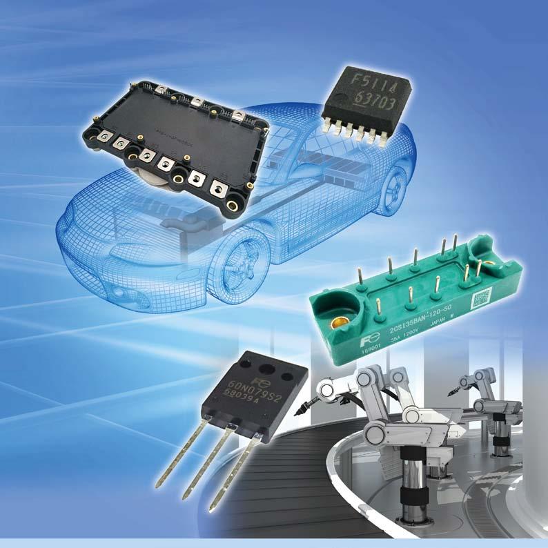
78 Printed on recycled paper
(a) All-SiC 2-in-1 module
 All-SiC 2-in-1 module") All-SiC -in- Module CHONABAYASHI, Mikiya * OTOMO, Yoshinori * KARASAWA, Tatsuya * A B S T R A C T Fuji Electric has developed an utilizing a SiC device that has been adopted in the development of a high-performance
All-SiC -in- Module CHONABAYASHI, Mikiya * OTOMO, Yoshinori * KARASAWA, Tatsuya * A B S T R A C T Fuji Electric has developed an utilizing a SiC device that has been adopted in the development of a high-performance
All-SiC Modules Equipped with SiC Trench Gate MOSFETs
 All-SiC Modules Equipped with SiC Trench Gate MOSFETs NAKAZAWA, Masayoshi * DAICHO, Norihiro * TSUJI, Takashi * A B S T R A C T There are increasing expectations placed on products that utilize SiC modules
Power Semiconductors Contributing in Energy Management
 Whole Number 247, ISSN 429-8284 4 214 Vol.6 No. Power Semiconductors Contributing in Energy Management 214 Vol.6 No. 4 Power Semiconductors Contributing in Energy Management Toward establishing low carbon
PrimePACK of 7th-Generation X Series 1,700-V IGBT Modules
 PrimePACK of 7th-Generation 1,7-V IGBT Modules YAMAMOTO, Takuya * YOSHIWATARI, Shinichi * OKAMOTO, Yujin * A B S T R A C T The demand for large-capacity IGBT modules has been expanding for power conversion
7th-Generation X Series RC-IGBT Module Line-Up for Industrial Applications
 7th-Generation X Series RC-IGBT Module Line-Up for Industrial Applications YAMANO, Akio * TAKASAKI, Aiko * ICHIKAWA, Hiroaki * A B S T R A C T In order to meet the market demand of the smaller size, lower
2nd-Generation Low Loss SJ-MOSFET with Built-In Fast Diode Super J MOS S2FD Series
 2nd-Generation Low Loss SJ-MOSFET with Built-In Fast Diode Super J MOS WATANABE, Sota * SAKATA, Toshiaki * YAMASHITA, Chiho * A B S T R A C T In order to make efficient use of energy, there has been increasing
High-power IGBT Modules
 High-power IGBT Modules Takashi Nishimura Yoshikazu Takamiya Osamu Nakajima 1. Introduction To help curb global warming, clean energy, rather than fossil fuels, has been used increasingly in recent years.
High Power IGBT Module for Three-level Inverter
 High Power IGBT Module for Three-level Inverter Takashi Nishimura Takatoshi Kobayashi Yoshitaka Nishimura ABSTRACT In recent years, power conversion equipment used in the field of new energy and the field
T-series and U-series IGBT Modules (600 V)
") T-series and U-series IGBT Modules (6 V) Seiji Momota Syuuji Miyashita Hiroki Wakimoto 1. Introduction The IGBT (insulated gate bipolar transistor) module is the most popular power device in power electronics
T-series and U-series IGBT Modules (6 V) Seiji Momota Syuuji Miyashita Hiroki Wakimoto 1. Introduction The IGBT (insulated gate bipolar transistor) module is the most popular power device in power electronics
2013 Vol.59 No. Power Semiconductors Contributing in Energy Management
 4 213 Vol.59 No. Power Semiconductors Contributing in Energy Management 213 Vol.59 No. 4 Power Semiconductors Contributing in Energy Management Cover Photo: FUJI ELECTRIC REVIEW vol.59 no.4 213 date of
1200 V SiC Super Junction Transistors operating at 250 C with extremely low energy losses for power conversion applications
 1200 V SiC Super Junction Transistors operating at 250 C with extremely low energy losses for power conversion applications Ranbir Singh, Siddarth Sundaresan, Eric Lieser and Michael Digangi GeneSiC Semiconductor,
4H-SiC V-Groove Trench MOSFETs with the Buried p + Regions
 ELECTRONICS 4H-SiC V-Groove Trench MOSFETs with the Buried p + Regions Yu SAITOH*, Toru HIYOSHI, Keiji WADA, Takeyoshi MASUDA, Takashi TSUNO and Yasuki MIKAMURA ----------------------------------------------------------------------------------------------------------------------------------------------------------------------------------------------------------------------------------------------------------
U-series IGBT Modules (1,700 V)
") U-series IGBT Modules (1,7 ) Yasuyuki Hoshi Yasushi Miyasaka Kentarou Muramatsu 1. Introduction In recent years, requirements have increased for high power semiconductor devices used in high power converters
U-series IGBT Modules (1,7 ) Yasuyuki Hoshi Yasushi Miyasaka Kentarou Muramatsu 1. Introduction In recent years, requirements have increased for high power semiconductor devices used in high power converters
SuperFAP-G Series of Power MOSFETs
 SuperFAP-G Series of Power s Hiroyuki Tokunishi Tadanori Yamada Masanori Inoue 1. Introduction In recent years, shipments of information and communication equipment, mainly network related equipment such
SuperLLD3 Series of 600 V Low-loss Fast-recovery Diodes
 SuperLLD3 Series of V Low-loss Fast-recovery Diodes Tetsuhiro Morimoto Taketo Watashima Masaki Ichinose 1. Introduction At present, societal problems such as global warming and environmental disruption
Hybrid Si-SiC Modules for High Frequency Industrial Applications
 Hybrid Si-SiC Modules for High Frequency Industrial Applications ABSTRACT This presentation introduces a new family of 1200V IGBT modules that combine high switching frequency optimized silicon IGBTs with
Fundamentals of Power Semiconductor Devices
 В. Jayant Baliga Fundamentals of Power Semiconductor Devices 4y Spri ringer Contents Preface vii Chapter 1 Introduction 1 1.1 Ideal and Typical Power Switching Waveforms 3 1.2 Ideal and Typical Power Device
USING F-SERIES IGBT MODULES
 .0 Introduction Mitsubishi s new F-series IGBTs represent a significant advance over previous IGBT generations in terms of total power losses. The device remains fundamentally the same as a conventional
Some Key Researches on SiC Device Technologies and their Predicted Advantages
 18 POWER SEMICONDUCTORS www.mitsubishichips.com Some Key Researches on SiC Device Technologies and their Predicted Advantages SiC has proven to be a good candidate as a material for next generation power
6th Generation Power MOSFET Super FAP-E 3S Low Q g Series
 6th Generation Power MOSFET Super FAP-E 3S Low Q g Series Ryu Araki Yukihito Hara Sota Watanabe 1. Introduction In recent years, efforts to address environmental issues have focused on the goal of reducing
New Power MOSFET. 1. Introduction. 2. Application of Power MOSFETs. Naoto Fujisawa Toshihiro Arai Tadanori Yamada
 New Power MOSFET Naoto Fujisawa Toshihiro Arai Tadanori Yamada 1. Introduction Due to the finer patterns and higher integration of LSIs, functions that were used a few years ago in minicomputers have now
V-Series Intelligent Power Modules
 V-Series Intelligent Power Modules Naoki Shimizu Hideaki Takahashi Keishirou Kumada A B S T R A C T Fuji Electric has developed a series of intelligent power modules for industrial applications, known
Wide Band-Gap Power Device
 Wide Band-Gap Power Device 1 Contents Revisit silicon power MOSFETs Silicon limitation Silicon solution Wide Band-Gap material Characteristic of SiC Power Device Characteristic of GaN Power Device 2 1
On-wafer GaN Power Semiconductor Characterization. Marc Schulze Tenberge Manager, Applications Engineering Maury Microwave
 On-wafer GaN Power Semiconductor Characterization Marc Schulze Tenberge Manager, Applications Engineering Maury Microwave Agenda 1. Introduction 2. Setup 3. Measurements for System Evaluation 4. Measurements
14 POWER MODULES
 14 POWER MODULES www.mitsubishichips.com Wide Temperature Operating Range of High Isolation HV-IGBT Modules Mitsubishi Electric has developed new High Voltage Insulated Gate Bipolar Transistor (HV-IGBT)
Power Semiconductor Devices
 TRADEMARK OF INNOVATION Power Semiconductor Devices Introduction This technical article is dedicated to the review of the following power electronics devices which act as solid-state switches in the circuits.
UNIT-VI FIELD EFFECT TRANSISTOR. 1. Explain about the Field Effect Transistor and also mention types of FET s.
 UNIT-I FIELD EFFECT TRANSISTOR 1. Explain about the Field Effect Transistor and also mention types of FET s. The Field Effect Transistor, or simply FET however, uses the voltage that is applied to their
Efficiency improvement with silicon carbide based power modules
 Efficiency improvement with silicon carbide based power modules Zhang Xi*, Daniel Domes*, Roland Rupp** * Infineon Technologies AG, Max-Planck-Straße 5, 59581 Warstein, Germany ** Infineon Technologies
High Reliability Power MOSFETs for Space Applications
 High Reliability Power MOSFETs for Space Applications Masanori Inoue Takashi Kobayashi Atsushi Maruyama A B S T R A C T We have developed highly reliable and radiation-hardened power MOSFETs for use in
Power MOSFET Zheng Yang (ERF 3017,
 ECE442 Power Semiconductor Devices and Integrated Circuits Power MOSFET Zheng Yang (ERF 3017, email: yangzhen@uic.edu) Evolution of low-voltage (
The Next Generation of Power Conversion Systems Enabled by SiC Power Devices
 Innovations Embedded The Next Generation of Power Conversion Systems Enabled by SiC Power Devices White Paper The world has benefitted from technology innovations and continued advancements that have contributed
High-Temperature and High-Frequency Performance Evaluation of 4H-SiC Unipolar Power Devices
 High-Temperature and High-Frequency Performance Evaluation of H-SiC Unipolar Power Devices Madhu Sudhan Chinthavali Oak Ridge Institute for Science and Education Oak Ridge, TN 37831-117 USA chinthavalim@ornl.gov
Numerical study on very high speed silicon PiN diode possibility for power ICs in comparison with SiC-SBD
 Numerical study on very high speed silicon PiN diode possibility for power ICs in comparison with SiC-SBD Kenichi Takahama and Ichiro Omura Kyushu Institute of Technology Senshui-cho 1-1, Tobata-ku, Kitakyushu
Sixth-Generation V-Series IGBT Module Application Note Chapter 1 Basic Concept and Features
 Sixth-Generation V-Series IGBT Module Application Note Chapter 1 Basic Concept and Features Table of contents Page 1 Basic concept of V series 1-2 2 Transition of device structure 1-3 3 Characteristics
Cree SiC Power White Paper: The Characterization of dv/dt Capabilities of Cree SiC Schottky diodes using an Avalanche Transistor Pulser
 Cree SiC Power White Paper: The Characterization of dv/dt Capabilities of Cree SiC Schottky diodes using an Avalanche Transistor Pulser Introduction Since the introduction of commercial silicon carbide
IGBT Module Chip Improvements for Industrial Motor Drives
 IGBT Module Chip Improvements for Industrial Motor Drives John F. Donlon Powerex, Inc. 173 Pavilion Lane Youngwood, PA USA Katsumi Satoh Mitsubishi Electric Corporation Power Semiconductor Device Works
Impact of Basal Plane Dislocations and Ruggedness of 10 kv 4H-SiC Transistors
 11th International MOS-AK Workshop (co-located with the IEDM and CMC Meetings) Silicon Valley, December 5, 2018 Impact of Basal Plane Dislocations and Ruggedness of 10 kv 4H-SiC Transistors *, A. Kumar,
SiC Transistor Basics: FAQs
 SiC Transistor Basics: FAQs Silicon Carbide (SiC) MOSFETs exhibit higher blocking voltage, lower on state resistance and higher thermal conductivity than their silicon counterparts. Oct. 9, 2013 Sam Davis
APPLICATION NOTE ANxxxx. Understanding the Datasheet of a SiC Power Schottky Diode
 APPLICATION NOTE ANxxxx CONTENTS 1 Introduction 1 2 Nomenclature 1 3 Absolute Maximum Ratings 2 4 Electrical Characteristics 5 5 Thermal / Mechanical Characteristics 7 6 Typical Performance Curves 8 7
SiC Power Schottky Diodes in Power Factor Correction Circuits
 SiC Power Schottky Diodes in Power Factor Correction Circuits By Ranbir Singh and James Richmond Introduction Electronic systems operating in the -12 V range currently utilize silicon (Si) PiN diodes,
High Performance ZVS Buck Regulator Removes Barriers To Increased Power Throughput In Wide Input Range Point-Of-Load Applications
 WHITE PAPER High Performance ZVS Buck Regulator Removes Barriers To Increased Power Throughput In Wide Input Range Point-Of-Load Applications Written by: C. R. Swartz Principal Engineer, Picor Semiconductor
Temperature-Dependent Characterization of SiC Power Electronic Devices
 Temperature-Dependent Characterization of SiC Power Electronic Devices Madhu Sudhan Chinthavali 1 chinthavalim@ornl.gov Burak Ozpineci 2 burak@ieee.org Leon M. Tolbert 2, 3 tolbert@utk.edu 1 Oak Ridge
Depletion-mode operation ( 공핍형 ): Using an input gate voltage to effectively decrease the channel size of an FET
: Using an input gate voltage to effectively decrease the channel size of an FET") Ch. 13 MOSFET Metal-Oxide-Semiconductor Field-Effect Transistor : I D D-mode E-mode V g The gate oxide is made of dielectric SiO 2 with e = 3.9 Depletion-mode operation ( 공핍형 ): Using an input gate voltage
Ch. 13 MOSFET Metal-Oxide-Semiconductor Field-Effect Transistor : I D D-mode E-mode V g The gate oxide is made of dielectric SiO 2 with e = 3.9 Depletion-mode operation ( 공핍형 ): Using an input gate voltage
1. Introduction. 2. Overview. Mitsuhiro Kakefu Masaki Ichinose
 Low I R Schottky Barrier Diode Series Mitsuhiro Kakefu Masaki Ichinose. Introduction Fig. Cross-sectional structure of SBD chip Representative of the recent trends towards smaller size and higher functionality
UNIT 3: FIELD EFFECT TRANSISTORS
 FIELD EFFECT TRANSISTOR: UNIT 3: FIELD EFFECT TRANSISTORS The field effect transistor is a semiconductor device, which depends for its operation on the control of current by an electric field. There are
Si, SiC and GaN Power Devices: An Unbiased View on Key Performance Indicators
 2016 IEEE Proceedings of the 62nd IEEE International Electron Devices Meeting (IEDM 2016), San Francisco, USA, December 3-7, 2016 Si, SiC and GaN Power Devices: An Unbiased View on Key Performance Indicators
New 1700V IGBT Modules with CSTBT and Improved FWDi
 New 17V IGBT Modules with CSTBT and Improved FWDi John Donlon 1, Eric Motto 1, Shinichi Iura 2, Eisuke Suekawa 2, Kazuhiro Morishita 3, Masuo Koga 3 1) Powerex Inc., Youngwood, PA, USA 2) Power Device
SiC-JFET in half-bridge configuration parasitic turn-on at
 SiC-JFET in half-bridge configuration parasitic turn-on at current commutation Daniel Heer, Infineon Technologies AG, Germany, Daniel.Heer@Infineon.com Dr. Reinhold Bayerer, Infineon Technologies AG, Germany,
Power Semiconductor contributing in energy and environment region
 ISSN 0429-8284 Whole Number 229 Power Semiconductor contributing in energy and environment region Power Semiconductor contributing in energy and environment region CONTENTS The Current Status and Future
IGBTs (Insulated Gate Bipolar Transistor)
") IGBTs (Insulated Gate Bipolar Transistor) Description This document describes the basic structures, ratings, and electrical characteristics of IGBTs. It also provides usage considerations for IGBTs. 1
IGBTs (Insulated Gate Bipolar Transistor) Description This document describes the basic structures, ratings, and electrical characteristics of IGBTs. It also provides usage considerations for IGBTs. 1
Unit III FET and its Applications. 2 Marks Questions and Answers
 Unit III FET and its Applications 2 Marks Questions and Answers 1. Why do you call FET as field effect transistor? The name field effect is derived from the fact that the current is controlled by an electric
CHAPTER I INTRODUCTION
 CHAPTER I INTRODUCTION High performance semiconductor devices with better voltage and current handling capability are required in different fields like power electronics, computer and automation. Since
A new compact power modules range for efficient solar inverters
 A new compact power modules range for efficient solar inverters Serge Bontemps, Pierre-Laurent Doumergue Microsemi PPG power module Products, Chemin de Magret, F-33700 Merignac Abstract The decrease of
Abstract: Following fast on the successful market introduction of the 1200V Soft-Punch-Through. 1. Introduction
 Novel Soft-Punch-Through (SPT) 1700V IGBT Sets Benchmark on Technology Curve M. Rahimo, W. Lukasch *, C. von Arx, A. Kopta, R. Schnell, S. Dewar, S. Linder ABB Semiconductors AG, Lenzburg, Switzerland
Fig. 1 - Enhancement mode GaN has a circuiut schematic similar to silicon MOSFETs with Gate (G), Drain (D), and Source (S).
, Drain (D), and Source (S).") GaN Basics: FAQs Sam Davis; Power Electronics Wed, 2013-10-02 Gallium nitride transistors have emerged as a high-performance alternative to silicon-based transistors, thanks to the technology's ability
GaN Basics: FAQs Sam Davis; Power Electronics Wed, 2013-10-02 Gallium nitride transistors have emerged as a high-performance alternative to silicon-based transistors, thanks to the technology's ability
Simulation Technology for Power Electronics Equipment
 Simulation Technology for Power Electronics Equipment MATSUMOTO, Hiroyuki TAMATE, Michio YOSHIKAWA, Ko ABSTRACT As there is increasing demand for higher effi ciency and power density of the power electronics
Gallium nitride (GaN)
") 80 Technology focus: GaN power electronics Vertical, CMOS and dual-gate approaches to gallium nitride power electronics US research company HRL Laboratories has published a number of papers concerning
80 Technology focus: GaN power electronics Vertical, CMOS and dual-gate approaches to gallium nitride power electronics US research company HRL Laboratories has published a number of papers concerning
SiC Cascodes and its advantages in power electronic applications
 SiC Cascodes and its advantages in power electronic applications WBG Power Conference, Munich, 5 th December 2017 Christopher Rocneanu Director Sales Europe and North America cro@unitedsic.com +4915121063411
DC-DC CONVERTER USING SILICON CARBIDE SCHOTTKY DIODE
 International Journal of Scientific & Engineering Research Volume 3, Issue 8, August-2012 1 DC-DC CONVERTER USING SILICON CARBIDE SCHOTTKY DIODE Y.S. Ravikumar Research scholar, faculty of TE., SIT., Tumkur
Failure Mechanisms and Robustness of Wide Band-Gap Devices under short-circuits and unclamped inductive switching
 Failure Mechanisms and Robustness of Wide Band-Gap Devices under short-circuits and unclamped inductive switching Stéphane Lefebvre (Cnam), Zoubir Khatir (IFSTTAR), Mounira Berkani (UPEC), Denis Labrousse
Development of New Generation 3.3kV IGBT module
 Development of New Generation 3.3kV IGBT module Mitsubishi_2_8 Seiten_neu.qxd 19.05.2006 12:43 Uhr Seite 2 CONTENT Development of New Generation 3.3kV IGBT module...........................................................
ELEC-E8421 Components of Power Electronics
 ELEC-E8421 Components of Power Electronics MOSFET 2015-10-04 Metal-Oxide-Semiconductor Field-Effect-Transistor (MOSFET) Vertical structure makes paralleling of many small MOSFETs on the chip easy. Very
Solid State Devices- Part- II. Module- IV
 Solid State Devices- Part- II Module- IV MOS Capacitor Two terminal MOS device MOS = Metal- Oxide- Semiconductor MOS capacitor - the heart of the MOSFET The MOS capacitor is used to induce charge at the
ELECTRONIC DEVICES AND CIRCUITS
 ELECTRONIC DEVICES AND CIRCUITS 1. At room temperature the current in an intrinsic semiconductor is due to A. holes B. electrons C. ions D. holes and electrons 2. Work function is the maximum energy required
Comparison of SiC and Si Power Semiconductor Devices to Be Used in 2.5 kw DC/DC Converter
 Comparison of SiC and Si Power Semiconductor Devices to Be Used in 2.5 kw DC/DC Converter M. G. Hosseini Aghdam Division of Electric Power Engineering Department of Energy and Environment Chalmers University
Field-Effect Transistor (FET) is one of the two major transistors; FET derives its name from its working mechanism;
 is one of the two major transistors; FET derives its name from its working mechanism;") Chapter 3 Field-Effect Transistors (FETs) 3.1 Introduction Field-Effect Transistor (FET) is one of the two major transistors; FET derives its name from its working mechanism; The concept has been known
Chapter 3 Field-Effect Transistors (FETs) 3.1 Introduction Field-Effect Transistor (FET) is one of the two major transistors; FET derives its name from its working mechanism; The concept has been known
GaN Based Power Conversion: Moving On! Tim McDonald APEC Key Component Technologies for Power Electronics in Electric Drive Vehicles
 1 GaN Based Power Conversion: Moving On! Key Component Technologies for Power Electronics in Electric Drive Vehicles Tim McDonald APEC 2013 2 Acknowledgements Collaborators: Tim McDonald (1), Han S. Lee
High Current Voltage Regulator Module (VRM) Uses DirectFET MOSFETs to Achieve Current Densities of 25A/in2 at 1MHz to Power 32-bit Servers
 Uses DirectFET MOSFETs to Achieve Current Densities of 25A/in2 at 1MHz to Power 32-bit Servers") High Current Voltage Regulator Module (VRM) Uses DirectFET MOSFETs to Achieve Current Densities of 25A/in2 at 1MHz to Power 32-bit Servers Ralph Monteiro, Carl Blake and Andrew Sawle, Arthur Woodworth
High Current Voltage Regulator Module (VRM) Uses DirectFET MOSFETs to Achieve Current Densities of 25A/in2 at 1MHz to Power 32-bit Servers Ralph Monteiro, Carl Blake and Andrew Sawle, Arthur Woodworth
Digital Electronics. By: FARHAD FARADJI, Ph.D. Assistant Professor, Electrical and Computer Engineering, K. N. Toosi University of Technology
 K. N. Toosi University of Technology Chapter 7. Field-Effect Transistors By: FARHAD FARADJI, Ph.D. Assistant Professor, Electrical and Computer Engineering, K. N. Toosi University of Technology http://wp.kntu.ac.ir/faradji/digitalelectronics.htm
CHAPTER 1 INTRODUCTION
 1 CHAPTER 1 INTRODUCTION 1.1 GENERAL Induction motor drives with squirrel cage type machines have been the workhorse in industry for variable-speed applications in wide power range that covers from fractional
FIELD EFFECT TRANSISTOR (FET) 1. JUNCTION FIELD EFFECT TRANSISTOR (JFET)
 1. JUNCTION FIELD EFFECT TRANSISTOR (JFET)") FIELD EFFECT TRANSISTOR (FET) The field-effect transistor (FET) is a three-terminal device used for a variety of applications that match, to a large extent, those of the BJT transistor. Although there
FIELD EFFECT TRANSISTOR (FET) The field-effect transistor (FET) is a three-terminal device used for a variety of applications that match, to a large extent, those of the BJT transistor. Although there
Pitch Pack Microsemi full SiC Power Modules
 Pitch Pack Microsemi full SiC Power Modules October 2014 SiC Main Characteristics vs. Si Characteristics SiC vs. Si Results Benefits Breakdown field (MV/cm) Electron sat. velocity (cm/s) Bandgap energy
AN1387 APPLICATION NOTE APPLICATION OF A NEW MONOLITHIC SMART IGBT IN DC MOTOR CONTROL FOR HOME APPLIANCES
 AN1387 APPLICATION NOTE APPLICATION OF A NEW MONOLITHIC SMART IGBT IN DC MOTOR CONTROL FOR HOME APPLIANCES A. Alessandria - L. Fragapane - S. Musumeci 1. ABSTRACT This application notes aims to outline
SRM INSTITUTE OF SCIENCE AND TECHNOLOGY (DEEMED UNIVERSITY)
") SRM INSTITUTE OF SCIENCE AND TECHNOLOGY (DEEMED UNIVERSITY) QUESTION BANK I YEAR B.Tech (II Semester) ELECTRONIC DEVICES (COMMON FOR EC102, EE104, IC108, BM106) UNIT-I PART-A 1. What are intrinsic and
SRM INSTITUTE OF SCIENCE AND TECHNOLOGY (DEEMED UNIVERSITY) QUESTION BANK I YEAR B.Tech (II Semester) ELECTRONIC DEVICES (COMMON FOR EC102, EE104, IC108, BM106) UNIT-I PART-A 1. What are intrinsic and
Symbol Parameter Typical
 PRODUCT SUMMARY (TYPICAL) V DS (V) 600 R DS(on) ( ) 0.29 Q rr (nc) 29 Features Low Q rr Free-wheeling diode not required Low-side Quiet Tab for reduced EMI RoHS compliant High frequency operation Applications
EEL 5245 POWER ELECTRONICS I Lecture #4: Chapter 2 Switching Concepts and Semiconductor Overview
 EEL 5245 POWER ELECTRONICS I Lecture #4: Chapter 2 Switching Concepts and Semiconductor Overview Objectives of Lecture Switch realizations Objective is to focus on terminal characteristics Blocking capability
An introduction to Depletion-mode MOSFETs By Linden Harrison
 An introduction to Depletion-mode MOSFETs By Linden Harrison Since the mid-nineteen seventies the enhancement-mode MOSFET has been the subject of almost continuous global research, development, and refinement
ENHANCING POWER ELECTRONIC DEVICES WITH WIDE BANDGAP SEMICONDUCTORS
 ENHANCING POWER ELECTRONIC DEVICES WITH WIDE BANDGAP SEMICONDUCTORS BURAK OZPINECI Oak Ridge National Laboratory Oak Ridge, TN 37831-6472 USA ozpinecib@ornl.gov MADHU SUDHAN CHINTHAVALI Oak Ridge Institute
Power Electronics Power semiconductor devices. Dr. Firas Obeidat
 Power Electronics Power semiconductor devices Dr. Firas Obeidat 1 Table of contents 1 Introduction 2 Classifications of Power Switches 3 Power Diodes 4 Thyristors (SCRs) 5 The Triac 6 The Gate Turn-Off
Difference between BJTs and FETs. Junction Field Effect Transistors (JFET)
") Difference between BJTs and FETs Transistors can be categorized according to their structure, and two of the more commonly known transistor structures, are the BJT and FET. The comparison between BJTs
Difference between BJTs and FETs Transistors can be categorized according to their structure, and two of the more commonly known transistor structures, are the BJT and FET. The comparison between BJTs
Logic Level Signal Isolation Technology Review. MARK CANTRELL Senior Applications Engineer
 Logic Level Signal Isolation Technology Review MARK CANTRELL Senior Applications Engineer 3/20/2017 Agenda Isolation Basics Technology Overview Inductive Capacitive and Optical Comparisons What really
Driving LEDs with SiC MOSFETs
 Power & Energy Efficiency POWERELECTRONICTIPS.COM Driving LEDs with SiC MOSFETs ADAM BARKLEY VIPINDAS PALA SiC Power Device Application Engineer Wolfspeed, a Cree Company Research Scientist Wolfspeed,
NAME: Last First Signature
 UNIVERSITY OF CALIFORNIA, BERKELEY College of Engineering Department of Electrical Engineering and Computer Sciences EE 130: IC Devices Spring 2003 FINAL EXAMINATION NAME: Last First Signature STUDENT
GS66516T Top-side cooled 650 V E-mode GaN transistor Preliminary Datasheet
 Features 650 V enhancement mode power switch Top-side cooled configuration R DS(on) = 25 mω I DS(max) = 60 A Ultra-low FOM Island Technology die Low inductance GaNPX package Easy gate drive requirements
FET. Field Effect Transistors ELEKTRONIKA KONTROL. Eka Maulana, ST, MT, M.Eng. Universitas Brawijaya. p + S n n-channel. Gate. Basic structure.
 FET Field Effect Transistors ELEKTRONIKA KONTROL Basic structure Gate G Source S n n-channel Cross section p + p + p + G Depletion region Drain D Eka Maulana, ST, MT, M.Eng. Universitas Brawijaya S Channel
DOWNLOAD PDF POWER ELECTRONICS DEVICES DRIVERS AND APPLICATIONS
 Chapter 1 : Power Electronics Devices, Drivers, Applications, and Passive theinnatdunvilla.com - Google D Download Power Electronics: Devices, Drivers and Applications By B.W. Williams - Provides a wide
High Voltage SPT + HiPak Modules Rated at 4500V
 High Voltage SPT + HiPak Modules Rated at 45V High Voltage SPT + HiPak Modules Rated at 45V A. Kopta, M. Rahimo, U. Schlapbach, R. Schnell, D. Schneider ABB Switzerland Ltd, Semiconductors, Fabrikstrasse
Fuji SiC Hybrid Module Application Note
 Fuji SiC Hybrid Module Application Note Fuji Electric Co., Ltd Aug. 2017 1 SiC Hybrid Module Application Note Chapter 1 Concept and Features Table of Contents Page 1 Basic concept 2 2 Features 3 3 Switching
The two-in-one chip. The bimode insulated-gate transistor (BIGT)
") The two-in-one chip The bimode insulated-gate transistor (BIGT) Munaf Rahimo, Liutauras Storasta, Chiara Corvasce, Arnost Kopta Power semiconductor devices employed in voltage source converter (VSC) applications
The two-in-one chip The bimode insulated-gate transistor (BIGT) Munaf Rahimo, Liutauras Storasta, Chiara Corvasce, Arnost Kopta Power semiconductor devices employed in voltage source converter (VSC) applications
Wide Band-Gap (SiC and GaN) Devices Characteristics and Applications. Richard McMahon University of Cambridge
 Devices Characteristics and Applications. Richard McMahon University of Cambridge") Wide Band-Gap (SiC and GaN) Devices Characteristics and Applications Richard McMahon University of Cambridge Wide band-gap power devices SiC : MOSFET JFET Schottky Diodes Unipolar BJT? Bipolar GaN : FET
Wide Band-Gap (SiC and GaN) Devices Characteristics and Applications Richard McMahon University of Cambridge Wide band-gap power devices SiC : MOSFET JFET Schottky Diodes Unipolar BJT? Bipolar GaN : FET
Power semiconductors. José M. Cámara V 1.0
 Power semiconductors José M. Cámara V 1.0 Introduction Here we are going to study semiconductor devices used in power electronics. They work under medium and high currents and voltages. Some of them only
How GaN-on-Si can help deliver higher efficiencies in power conversion and power management
 White Paper How GaN-on-Si can help deliver higher efficiencies in power conversion and power management Introducing Infineon's CoolGaN Abstract This paper describes the benefits of gallium nitride on silicon
A 6.5kV IGBT Module with very high Safe Operating Area
 A 6.5kV IGBT Module with very high Safe Operating Area A. Kopta, M. Rahimo, U. Schlapbach, D. Schneider, Eric Carroll, S. Linder IAS, October 2005, Hong Kong, China Copyright [2005] IEEE. Reprinted from
FET. FET (field-effect transistor) JFET. Prepared by Engr. JP Timola Reference: Electronic Devices by Floyd
 JFET. Prepared by Engr. JP Timola Reference: Electronic Devices by Floyd") FET Prepared by Engr. JP Timola Reference: Electronic Devices by Floyd FET (field-effect transistor) unipolar devices - unlike BJTs that use both electron and hole current, they operate only with one type
FET Prepared by Engr. JP Timola Reference: Electronic Devices by Floyd FET (field-effect transistor) unipolar devices - unlike BJTs that use both electron and hole current, they operate only with one type
by Shoichiro Hirai *, Naoya Arakawa *, Takahiro Ueno *2, Hiroki Hamada *2, Isao Tomomatsu *3 and Yoichi Iso *4 1. INTRODUCTION
 by Shoichiro Hirai *, Naoya Arakawa *, Takahiro Ueno *2, Hiroki Hamada *2, Isao Tomomatsu *3 and Yoichi Iso *4 Recently the development of information-intensive society around us is quite ABSTRACT remarkable,
Intelligent power MOSFET
 Intelligent Power MOSFETs Shin Kiuchi Motoi Kudoh Naoki Yaezawa 1. Introduction The development of automotive electronics is accelerating year after year. Currently, the percentage of cars equipped with
SJEP120R125. Silicon Carbide. Normally-OFF Trench Silicon Carbide Power JFET. Product Summary
 NormallyOFF Trench Power JFET Features: Compatible with Standard PWM ICs Positive Temperature Coefficient for Ease of Paralleling Temperature Independent Switching Behavior 175 C Maximum Operating Temperature
INTRODUCTION: Basic operating principle of a MOSFET:
 INTRODUCTION: Along with the Junction Field Effect Transistor (JFET), there is another type of Field Effect Transistor available whose Gate input is electrically insulated from the main current carrying
Power Devices. 7 th Generation IGBT Module for Industrial Applications
 Power Devices 7 th Generation IGBT Module for Industrial Applications Content 7 th Generation IGBT Module for Industrial Applications... 3 1. Introduction... 3 2. Chip technologies... 3 2.1. 7 th generation
235 W Maximum Power Dissipation (whole module) 470 T J Junction Operating Temperature -40 to 150. Torque strength
 470 T J Junction Operating Temperature -40 to 150. Torque strength") Discontinued PRODUCT SUMMARY (TYPICAL) V DS (V) 600 R DS(on) (m ) 30 GaN Power Hybrid HEMT Half-Bridge Module Features High frequency operation Free-wheeling diode not required Applications Compact DC-DC
Discontinued PRODUCT SUMMARY (TYPICAL) V DS (V) 600 R DS(on) (m ) 30 GaN Power Hybrid HEMT Half-Bridge Module Features High frequency operation Free-wheeling diode not required Applications Compact DC-DC