BAF. Benefield Anechoic Facility H A N D B O O K. Air Force Test Center 412th Test Wing
|
|
|
- Gabriella Nash
- 6 years ago
- Views:
Transcription

1 Benefield Anechoic Facility BAF H A N D B O O K Air Force Test Center 412th Test Wing Electronic Warfare Group/772d Test Squadron Edwards Air Force Base, California 412TW-PA October 2012

2 F-22 EMI/EMC Tests 412 TW EWG MISSION Provide our nation and its allies the expertise and credible capabilities to perform Electronic Attack and Survivability Test and Evaluation ensuring our continued world-wide air dominance Global Hawk EMI/EMC Tests 2

3 BAF MISSION The Electronic Warfare Group (EWG) 772d Test Squadron s Benefield Anechoic Facility (BAF) will provide a comprehensive, robust and scalable radio frequency (RF) test and evaluation (T&E) infrastructure and capability to ensure weapons system survivability and mission effectiveness for the DoD, industry and our allies. We will provide invaluable resources within our technical support and capabilities as uniquely required by the specific program in the areas of: An exclusively large anechoic chamber facility Complete end-to-end installed systems test Dense, high fidelity RF threat simulation and verification Electronic countermeasures collection, measurement and analysis Radar target return and ECM simulation Antenna pattern measurement Intra- and Inter-Systems Electromagnetic (EM) Interoperability and Compatibility (EMI/EMC) Electromagnetic environmental effects (E3) measurements Global positioning system (GPS) signal generation Proficient RF and EW systems and systems test engineering expertise and know-how State-of-the-Art RF, digital and video instrumentation infrastructure Documentation from test requirements to the final test report Singapore F-15 EW Suite and Radar Tests 3
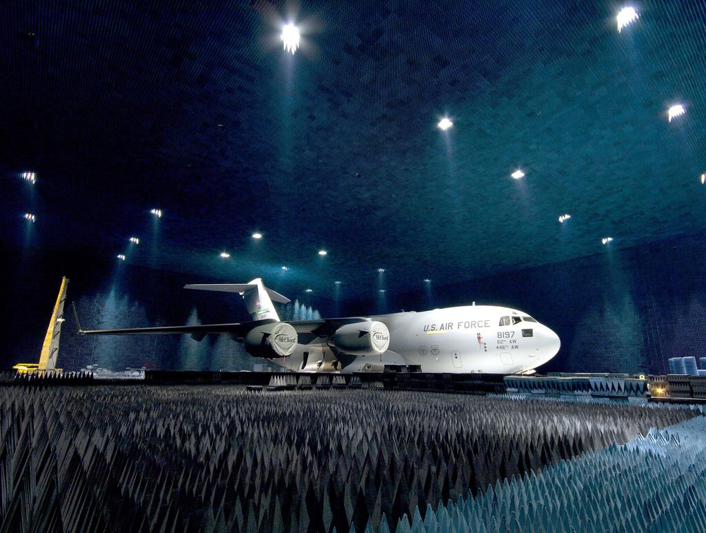
4 OVERVIEW This handbook presents the test capabilities and applications of the BAF for the test and evaluation of current and future RF systems. The BAF is located at Edwards Air Force Base (AFB), California, at the southwest end of the Edwards AFB flight line. It is the largest anechoic test facility in the world providing a virtual open-air range (OAR) within four walls and ceiling. It is capable of supporting and handling virtually all Department of Defense (DoD) aircraft with very few exceptions. The 772 TS provides comprehensive systems and test engineering applied to the development and the T&E of military and commercial RF systems. It supports developmental engineering tests, Developmental T&E (DT&E) as well as Operational T&E (OT&E). Typical users of the BAF had been the developers, integrators, testers and users of Electronic Combat systems (e.g. radar warning receivers, electronic countermeasures, etc.) in a secure, controlled installed system test facility. Today, with the increased demand posed by integrated and newer net-centric RF systems and their required compatibility and interoperability, it has also matured and improved into a valuable tool for today s highly integrated weapons systems. It is used to test manned and unmanned systems in the areas of: SIGINT and ELINT systems Network centric systems of systems Communications and navigation Identification friend and foe (IFF) GPS Radar systems Radar warning receivers Electronic Countermeasures (On-board and off-board) The BAF s main anechoic chamber measures 264 ft L x 250 ft W x 70 ft H. The size allows for far field RF radiation, thereby making simulations more accurate. Inside the chamber is a 175 ton, 80-ft diameter turntable that can rotate an aircraft ±180. The chamber also utilizes two 40-ton capacity hoists to lift a fighter-sized aircraft. The RF shielding effectiveness of the chamber from the outside world from 0.01 to 18 GHz is approximately 100 db. The approximate quiet zone isolation inside the chamber is shown below for the following frequencies: 500 MH 72 db 1.0 GHz 84 db 2.0 GHz 96 db GHz 100 db 4
 from potential chamber reflections. See pages 20 and 21 time-gating discussions.")
5 Below 500 MHz, we achieve desirable quiet zones on unique case-by-case configurations (based on the unique test objectives and SUT characteristics). We use special techniques available at the BAF to isolate the system-under-test (SUT) from potential chamber reflections. See pages 20 and 21 time-gating discussions. The BAF facilitates the testing of integrated avionics systems in a secure, controlled and repeatable electromagnetically-managed environment using simulation and stimulation technologies that closely replicate real combat mission environments. The facility provides multiple simulated ground, sea, and airborne threat systems (EW and communications signals) radiated into the large test chamber creating a complex and dense electromagnetic environment which provides a realistically representative battle-space. The BAF test facility is used to characterize a system s performance or to investigate anomalies associated with source and victim RF systems installed on a ground or air vehicle, or simply due to basic installation effects. The electromagnetic susceptibility or vulnerability of critical mission systems is tested in the BAF with its instrumented, very capable, Radiated Susceptibility Test System. The BAF is part of a major range and test facility base (MRTFB) that provides unique test capabilities to the DoD and the Defense Acquisition System, industry and our allies with costeffective rates and core capabilities. Contact the BAF to discuss your unique test requirements, our capabilities, cost estimates and schedule. RAF Tornado Multi-Ship Radar ECCM Test 5
6 CAPABILITIES... EW RF THREAT ENVIRONMENT GENERATION The BAF has highly sophisticated RF signal generation and monitoring capabilities to test RWR, ESM, ECM (Electronic Combat/Attack or Jammers ), Radar, SIGINT or ELINT systems. Virtually any threat or friendly emitter can be reproduced for free-space radiation or direct injection for the stimulation and test of EW/IO systems. This capability is also important for the comprehensive EMI/EMC testing of both integrated and stand-alone RF systems and other avionics such as a radar system on an air vehicle. Installed systems RF compatibility-interoperability testing, which is paramount to ensure that systems are ready to provide the mission effectiveness and survivability, can be accomplished. Flying the system in the BAF using a build-up approach into a heavy dense environment allows discovery of system issues prior to costlier flight test and provides scenarios or densities that may not be available at open air ranges for installed systems test. At the heart of the RF generation complex for these tests is a Combat Electromagnetic Environment Simulator (CEESIM, MKN Version). The RF generation and injection system provides high-fidelity, dynamic and dense RF environments which can include threat and friendly radars and typical background signals. The BAF with the CEESIM and its free-space RF generation capability provides world-class high fidelity stimuli to EW/IO systems. Any known threat in the national databases can be simulated. Engagements (scenarios) and RF power levels at the SUT can be programmed to represent a large segment of the geographical battle-space. Threat lay-downs are tailored or newly designed to match the SUT s test requirements and the expected battlespace for the weapons system. Libraries can be existing ones that include hundreds of emitters that can be reused, tailored, or newly built from customer inputs. The main RF free space transmission subsystem (see figure on next page) is highly mobile within the BAF and consists of twenty (20) mobile RF transmission systems (threat sites) (24 channels total) while the direct injection method provides up to 80 ports of phase and amplitude controlled RF injection. The system operators can program and radiate the frequency, power, pulse width, pulse shape, pulse modulation (inter- and intra-pulse), pulse repetition interval, pulse repetition frequency, transmit antenna patterns, and perform complex AM, FM, PM, FSK, and PSK modulations. The number of simultaneous threats depends on the duty cycle of the chosen emitters and the desired fidelity of the simulation (e.g., 1.35 million pulses per second with 10 CW emitters and a dropout of 3%). For direct injection, the system performs angle-of-arrival (AoA) antenna response modeling, which supports the testing of sensors that use amplitude-based and/or phase interferometerbased angle measurements. This allows for full motion simulation of the RF emitters. 6

7 7 CEESIM provides: Land-based, Sea-based, Airborne radars Early warning, acquisition, tracker, launch simulations CW, pulsed ranging, Doppler Various high fidelity modulations Dynamic scenarios of these signals as scripted by the customer requirement Control Computer and GUI Digital Generation System Mobile Distribution Patch Unit Modulations include AM, FM, PM, FSK, PSK, and others. Low Band RF Generation Mobile Carts (4) Low Band: GHz 4 channels Mid Band RF Generation Mobile Carts (4) Mid Band: GHz 8 channels Dual Band RF Generation Mobile Carts (4) Antenna Height adjustable from 7 35 ft Aircraft Position: Up to approx. 50 ft depending on aircraft (or SUT on turntable) 20 carts provide up to 24 highly mobile reconfigurable and reprogrammable channels as dedicated or multiplexed channels for higher density scenarios High Band: GHz 12 channels High Band RF Generation Mobile Carts (8) Free-Space CEESIM RF Scenario Generation

 in response to the radar s emission.")
 based RF generation system consists of a Low Band (0.")
 simultaneous time coincident returns and the high band generates one (1). Range is programmable out to 200 nm.")
8 ... CAPABILITIES RADAR TARGET AND ECM ENVIRONMENT SIMULATION The BAF provides a programmable radar target and ECM generator (RTG) capable of generating synthesized radar targets (returns or echoes) which are observed by an on-aircraft radar system as it would in flight. The Advanced Radar Environment Simulator (ARES) RTG system has three channels simulating and delivering returns with correctly simulated range, range rate, target radar cross-section and Doppler (± shifts) in response to the radar s emission. At the BAF the tester can evaluate radar performance in an installed configuration independently or in the presence of EW systems (RF threats) and ECM (jamming on-board and off-board) for interoperability testing. The digital RF memory (DRFM) based RF generation system consists of a Low Band (0.3 GHz to 18 GHz) and a High Band (18 GHz to 40 GHz) at an operating instantaneous bandwidth of MHz centered at any point within each band. The low band can generate two (2) simultaneous time coincident returns and the high band generates one (1). Range is programmable out to 200 nm. Additionally, radar targets have programmable features or characteristics that can include: Scintillation effects, jet engine modulation (JEM) patterns and variations Various non-coherent noise ECM response with variable J/S Coherent ECM coordinated (time and J/S) with an external jammer to augment ECM techniques The ECM capability (reactive and non-reactive) utilizing the ARES external jammer support feature is beneficial when testing a radar with ECM pods or jammers to test interoperability or electronic counter-countermeasures (ECCM). BAF Radar Test Configuration Free Space ARES Injection Facility Interface External ECM Radar Display 4. Video Injection Mission Computer 3. Digital Message Injection Radar Receiver Radar Antenna 2. RF Injection 1. RF Two-Way Free Space + IFF/RCS/JEM ARES ARES Radar Target and ECM Simulation 8
 for friendly situational awareness information, a Link-16 Simulations and Stimulation Suite and the Global Positioning System Simulator (GPSS).")
9 ... CAPABILITIES COMMUNICATIONS, NAVIGATION, AND IDENTIFICATION (CNI) SIMULATORS The BAF s CNI suite consists of the Joint Communications Simulator (JCS) for friendly and hostile signals, the Strategic Data Link Simulator (SDLS) for friendly situational awareness information, a Link-16 Simulations and Stimulation Suite and the Global Positioning System Simulator (GPSS). A GSM Cell network is also available. The Link-16 suite, the KU-Band SatCom Link and Digital Integrated Air Defense system (DIADS) capabilities enable network-centric operations and distributed test possibilities. These tools provide the capability to test and the visibility to understand a system s operation in system of systems, RF dense, operationally representative environments with coherent, secure, and known conditions. Joint Communications Simulator (JCS) The JCS system provides customers with a programmable, scenario based, complex RF signal generation system capable of creating a realistic CNI RF environment of up to 72 simultaneous emitters for up to 2000 CNI emitters (per scenario) covering frequencies from 500 khz to 18 GHz. There is a robust JCS library of friendly and hostile signals; many basic waveforms such as AM, FM, SSB, DSB, pulsed, phase, and frequency shift keying; and new waveforms can be programmed. Pulsed signals such as IFF signals can be time shared providing RF emitter densities well in excess of 100 s of signals. Interrogations in Modes 1, 2, 3/A, C, S (all uplink formats) and 5 (Levels 1 and 2) and replies in Modes 1, 2, 3/A, C, and 4 are available. The data content of SUT IFF interrogations and transponds in any mode can be decoded and deciphered by the JCS SUT data capture capability. As part of the 72 simultaneous signals, JCS provides FRUIT (Friendly Replies Unsynchronized in Time) to a SUT interrogator to supply more realistic environments. The JCS has a portable capability and is currently undergoing AIMS certification (late 2012). The BAF also has AIMS-certified test sets. Simulation Controller System Under Test (SUT) Graphical User Interface and Displays External Control Real-Time Control Output Data External Control SUT Interrogations, Responses Note: RF can be hard-wired also Free-space radiation RF 1 through RF N Real-Time Signal Processing RF Signal Generators RF Network and Control Scenerio Geometry Processing Signal Events Generator Resource Control and Allocation Background Signals Communication Signals Identifications (IFF) Navigation Signals Signal 1 Signal 2 Signal 3. Signal N Amplitude Frequency Phase RF Routing Switching and Summing JSC Simplified Block Diagram 9

10 Strategic Data Link Simulator (SDLS) The SDLS system provides a scenario-based, computer-controlled simulator with operational multi-channel UHF radios providing real world broadcasts of selected line-of-sight or satellite communication tactical data links. This creates a realistic joint battlefield environment for evaluating system performance, interoperability, off-platform cueing and situational awareness. Data links available include the Tactical Information Broadcast System (TIBS) and the Tactical Digital Information Link-11 (limited). Link-16 Network Simulation and Stimulation The tool suite needed to monitor, test, and document Link 16 performance is available. The Advanced Communication Environment (ACE)/Faithful Timeslot Messaging (FTM) system renders a high-fidelity, operationally representative Link-16 network test environment with precise timeslot by timeslot signal time of arrival, signal strength, and message content per the network design and scenario. Propagation delay is based upon scenario ranges while attenuation is based upon ranges, power, and antenna patterns. The BAF Link-16 suite also includes the Multi-Link System Test Training Tool (MLST3). It presents a comprehensive RF rest-of-the-world simulation for testing Link-16 terminals and their platforms in fully populated, dynamic L-Band RF environments. The MLST3 and ACE-FTM both operate stand alone or as part of actual networks and have the ability to interactively exchange Link 16 messages in a distributed environment. It can introduce Link 16 message errors to test interoperability and error handling. The Link Environment Gateway Simulator (LEGS) provides an additional Link-16 simulation capability as well as providing Link 16 terminal operational insight and recording. A Link-16 Management System (LMS-16) provides independent data capture of Link-16 RF transmissions. BAF Real-World Free-Space EME 10
 allows GPS tracking and jamming tests without FCC, FAA, or Base Frequency Management approval.")
11 GLOBAL POSITIONING SYSTEM (GPS) SIMULATION AND TEST The BAF is an excellent facility to conduct GPS testing. The chamber shielding effectiveness ( 100dB) allows GPS tracking and jamming tests without FCC, FAA, or Base Frequency Management approval. GPS signals can be transmitted free-space to the SUT using one of three simulators: the GPS Simulation system, GPS Retransmission System or the Advanced Global Navigation Simulator (AGNS) GPS simulator. The Interstate Electronics GPS Simulation System is capable of generating 24 fully independent RF channels of L1 ( MHz) and L2 ( MHz) GPS signals. It can be configured in combinations of GPS Space Vehicle signals, GPS Ground Transmitter signals, GPS multipath signals, GPS spoofers, and jammers, or up to 12 full up L1/L2 satellites transmitted over a single RF channel. The systems can be used to quickly setup or modify a signal with both Course Acquisition (C/A) code and Precision (P(Y)) code and simulates receiver vehicle motion. The GPS Retransmission System repeats an external GPS L1 signal from outside the BAF into the chamber. The Government-developed AGNS GPS simulator (available late 2012) provides sixteen (16) RF channels into seven (7) separate L1 and L2 transmit antennas. This is significant for testing GPS steering and nulling antenna systems (e.g. CRPA). The AGNS system can simulate C/A, L2C, P and P(Y) and M codes to support Advanced Encryptions Code (AEC). The system can be configured for L5 carriers and the Modernized NAVSTAR Security Algorithm (MNSA). GPS Illustration 11


12 Data Distribution Center Instrumentation GPS RF Carts CEESIM ARES 12 Test Control Room CNI RF Environment Monitor Fiber to DIADS, TEMS/IFAST JCS SDLS TDLS LMS-16 LEGS GM MSim See CNI sections for details of these capabilities. A Sample of a Complex Battlespace Electro-Magnetic Environment (EME)
.")


13 ... CAPABILITIES DISTRIBUTED TESTING AND CONNECTIVITY KU-Band SATCOM Link The KU-Band SATCOM system installed in the BAF provides bi-directional, uplink and down link connectivity between a SATCOM-equipped SUT in the chamber and its ground station or Mission Control Element (MCE). With the up and down converters, filters, and RF over fiber transceivers, chamber emissions are isolated from the outside world and all security and links are preserved. With this capability, the remote MCE or other ground stations are able to communicate with the SUT, control and monitor SUT operations, and obtain KU-Band data streams all while testing in the chamber. Data can be captured real-time at the vehicle s ground stations. This capability, used for the RQ-4 Global Hawk test efforts, is available for use with other manned or unmanned vehicles that are equipped with a KU-Band SATCOM capability. Ku-Band satellite communications Mission Control Element & to Distributive Ground Station C 2 and Sensor Link Ku Band signal Fiber-opticlink to dish outside BAF Sensors BAF KU-Band SatCom Illustration Joint Mission Environment Test Capability (JMETC) The BAF is a member facility of the JMETC group and can provide distributed testing or the capability for linking distributed facilities, enabling DoD customers to develop and test warfighting capabilities in a Joint context. Distributed test architectures available include DIS, TENA and JREAP utilizing the DREN and SDREN networks. 13
14 14
15 ... CAPABILITIES RF ENVIRONMENT MONITORING SYSTEM The RF environment is monitored by a robust but flexible suite of mobile and reconfigurable RF monitoring equipment that provides real-time quality checks of the active test scenarios as well as checks for intentional and unintentional RF emissions from the System Under Test (SUT). Data, such as precision pulse widths, RF frequency, pulse intervals, and high resolution power are available to the customer in real-time and as part of a data package. At the heart of the suite are the Agilent 4400 series spectrum analyzers and the SP-500 and CS-3002 ELINT or RF collection systems. Post-test, the data is provided on media to the customer. The monitoring carts provide data collection, processing, monitoring, display, and storage of the Radio Frequency (RF) environment. Normally one or two carts are designated as CEESIM direct monitoring carts that are directly coupled to the CEESIM channel outputs and provide health and RF power truth data for the scenario emitters at the antennas. Agilent 4400 series spectrum analyzers are used in these carts along with remote switching devices, amplifiers, and video transmitters to remotely collect and display this information in the Test Control Room (TCR) for the test engineer or customer personnel. The SP-500, Radio Frequency (RF) pulse analyzer, is at the core of the suite of collection devices and allows each RF pulse that is generated to be captured for up to one million pulses per second, from 250 MHz to 18 GHz. The captured RF and its signal characteristics are available as Pulse Descriptor Words (PDWs). The SP-500 is used for both capturing data during BAF test missions and at the open air ranges for signal correlation work. SP-500s are mobile and reconfigurable for each test requirement. Available in the TCR, these PDWs are also used at the workstations in the TCR to identify all RF threat emanations in the chamber and are compared real-time to the test s library and displayed on an active emitter display with the appropriate parameters and ID. The SP-500 tuners can constantly sweep the environment or be set to specific frequencies or spectrum of interest in a number of selectable bandwidths. The CS-3002 Pulse Analyzer Unit (PAU) consists of a Dual-Channel (RF) pulse analyzer unit (PAU), two 500 MHz 18 GHz tuners and its User Interface. It captures each RF pulse that is generated for up to four million pulses at a rate of 2.5 million per sec. RF monitoring configurations uniquely designed for each customer or test provides necessary real-time data and control while also making it available for post-test analysis. A RF monitoring configuration is illustrated on the following page. 15
16 24 Port GB Ethernet Switch 16 10/100/1000 Ethernet Switch Data Archive SERVER (PC) North Tower Room /100/1000 Ethernet Switch Real Time Monitoring And Recording Test Control Room 10/100/1000 Ethernet Switch CEESIM Digital Generator SP-500 DATA Server Threat Site 2 CEESIM Threat Simulator Carts High Band Cart(s) Low Band Cart(s) Mid Band Cart(s) High Band Cart(s) Low Band Cart(s) Mid Band Cart(s) NW Quad RF Switch Matrix Mobile (360º) Threat Site Antennas 24 Channels NE Quad RF Switch Matrix 10/100/1000 Ethernet Switch Spectrum Analyzer SpecAn (E4440 Series) 10/100/1000 Ethernet Switch SP-500 Cart North RF Switch Matrix South SP-500 Cart and Switch Matrix Free Space Spectrum Analyzer.1-26 GHz Chamber Sample of RF Monitoring Configuration for Chamber Testing
17 ... CAPABILITIES ELECTROMAGNETIC ENVIRONMENTAL EFFECTS (E3) E3 test capabilities at the BAF include radiated and conducted emissions, radiated and conducted susceptibility, victim-source EM compatibility, antenna-to-antenna isolation, radio scan, EMI/EMC and effective radiated power (ERP). Full aircraft testing is accomplished in the large chamber and line replaceable unit emission and susceptibility testing is conducted in a small adjacent anechoic chamber. The BAF radiated susceptibility (RS) test system provides an integrated, turnkey solution to our customers requirement to test installed aircraft system operation in the presence of high power RF fields. Fielded systems have a greater dependence on electrical and electronic systems to perform functions required for continued mission effectiveness, safe flight and landing of aircraft in a high intensity RF environment. The need for this type of testing is due to reduced electromagnetic shielding afforded by some composite materials used in various applications and designs, and an increased presence of high power RF signals in the everyday electromagnetic environment. There is also an increased susceptibility of electrical and electronic systems to high intensity radiated fields (HIRF). This is due to increased data bus or processor operating speeds, higher-density integrated components and circuit cards that create a generally greater sensitivity of the electronic equipment in aircraft. This makes RS testing imperative to ensure system effectiveness and flight safety. The BAF provides a powerful capability in this area and compares to the military and commercial standards (for example, MIL-STD 464 and SAE 5583) shown on the following page. Electromagnetic Interference (EMI) testing is available for unintentional emissions, and out-ofband emissions. EMI receivers have frequency range coverage from 100 Hz to 40 GHz. They are capable of a large RF dynamic range for sensitive EMI measurements in conformance with MIL- STD 461F standards or customers specified requirements. 17
18 18 Electrical Field, (Volts/Meter) MIL-STD-464C SAE-5583 MIL-STD-461E BAF E 3 Capability (Blue Area) Start Freq End Freq V/m Avg 20 MHz 100 MHz MHz MHz Frequency, Mhz Radiated Susceptibility Test Capability
.")
19 ... CAPABILITIES ANTENNA PATTERN AND ISOLATION MEASUREMENTS The BAF offers a variety of antenna pattern measurement methods. The antenna measurement equipment functions in the frequency range from 100 MHz to 50 GHz (chamber/sut interactions are considered at low frequencies). The antenna pattern measurement system is capable of collecting data on twelve (12) antennas at a time in both amplitude and phase as frequency is stepped through the operating band. The antenna pattern can be measured in vertical, horizontal, right hand circular, left hand circular, slant linear and axial ratio. The BAF can typically measure 30 degree elevation swings for a hoisted aircraft and depends on SUT specific geometrical considerations and frequency of interest. Both standalone and installed patterns are provided. Installed patterns can be supplied for any size aircraft up to that of a C-17. Data options include phase and amplitude data for varying elevations, and up to 360º of azimuth. Azimuth data resolution can be as granular as one degree. To increase the chamber s measurement space, time gating (in the low nanosecond range) techniques are applied for lower frequencies ( 500 Mhz)or for other special requirements. This virtually expands the chamber s usable measurement volume by negating potential reflections from the walls, ceiling and floor. See figure on page 21. Key to system interoperability and compatibility is own-ship inter- and intra-system antenna to antenna isolation. At the BAF, with today s RF-reliant weapons systems with numerous mission systems operating in the same spectrum, typical flight configurations and modes can be characterized so that the developer and user know how systems will behave in-flight. This information is essential to evaluate mission effectiveness and suitability requirements. RAAF F-18 Installed Antenna Pattern Tests 19

20 Sample antenna pattern data product from a BAF test. Without time gating: Unreliable or unstable data perturbated by effects of chamber reflections. Test run at 150MHz. With time gating techniques: Data is reliable and effectively measures SUT response or performance. Test run at 150MHz. 20
 system impacts on the battlespace.")
21 ... CAPABILITIES DIGITAL INTEGRATED AIR DEFENSE SYSTEM The 772 TS developed and maintains the Digital Integrated Air Defense System (DIADS). It accurately simulates command and control (C2) system impacts on the battlespace. DIADS incorporates a software representation of the algorithms used by modern enemy air defense systems currently deployed throughout the world. The simulation can be operated stand-alone, faster than real-time for constructive use, or in various Operator-in-the-Loop/Hardware-in-the- Loop real-time modes. DIADS simulates several generations of surface to air missile systems, radars, tracking algorithms and command and control nodes many of which represent real systems that are deployed or are expected to be deployed. DIADS provides critical insight into the survivability of DoD weapon systems operating in hostile airspace. The modeling allows testing against individual threats in a 1v1 or 1vMany scenario up to full up mission level testing to stress operational plans and support full scale Red Flag exercises. It provides insight into the total RF environment expected in combat by faithfully representing the signals that pilots and systems will encounter when facing the enemy. DIADS has extensive interfacing capabilities and can be used in support of a larger test or to host the entire test using standard interfaces such as DIS, TENA, and ASTERIX to interact with test customers as well as participate in distributed test and training exercises. DIADS provides insight into the total RF environment expected in combat with extensive interfacing capabilities and is integrated with multi-spectral environment generators, external simulations, models, and T&E assets. Sample DIADS Engagement Simulation 21

22 DATA RESOURCES The BAF provides graphical displays and a variety of formatted data types during a test for realtime test visualization and control in the Test Control Room. Post test data reduction, formatting, and plotting is performed in-house to meet customer needs, as required. Flexible and Comprehensive time-correlated data products include merged and singular products of: Real-time displays of data from SUT, chamber videos and data collection and measuring systems (see figure below) PCM, RS422, RS232 Eight (8) channels real-time monitoring of Mil-Std-1553B data streams (four (4) channels recorded 1553B) RF threat generation activity files Turntable position data or position representing TSPI RF environment monitoring system data Digitized video and intercom audio Antenna pattern and antenna coupling (isolation) plots Formats common to the EW open air ranges (OARs) allows the use of common tools and data products for ground (BAF) and flight test (OAR) comparisons Sample Real-Time TCR Display During Test 22

23 Programs that have taken the BAF Advantage... CV-22 self protection suite performance and antenna measurements Global Hawk and Euro Hawk Tests RAAF F-18 Avionics-Radar-Jammer Interoperability characterization RAF Tornado Multi-ship Radar ECCM Trial DIADS support for Air Force Operational Test and Evaluation Command (AFOTEC) F/A-22 and F-35 JSF test C-130J EW Suite (ground test risk reduction prior to EW open air flight test) F-16 HARM Targeting System, ALR-69, AIDEWS (AN/ALQ-211) F/A-22 Test F/A-18 Antenna Pattern Measurement Test F-16 RWR Uninstalled Antenna Pattern Measurement Test BMW automobiles (first foreign commercial test, electromagnetic compatibility test) 23

24 FLY YOUR SYSTEM IN THE BAF! Established robust capabilities scalable and reconfigurable to meet your program requirement whether your system is at a Technology Readiness Level 4 or Level 9 Breadth includes a full complement of avionics and ground systems simulation and stimulation along with measurement and reporting capabilities Evaluate system maturity and baseline at installed air vehicle level to reduce risk and increase productivity in future testing, including open-air-range (OAR) testing Reduces cost, schedule and risk Can reduce flight time (runs), unknowns and re-fly rate Obtain statistically significant samples sizes rapid test execution of numerous runs and repeatability of test points Explore areas of specific interest on systems that cannot be tested on flight line or in flight Exercise classified capabilities in a protected environment with realistic EME densities or capabilities restricted be regulatory agencies such as FAA, FCC or frequency management Obtain data for airworthiness certification 24


25 SECURITY and ACCESS CLASSIFICATION LEVELS The BAF is capable of supporting both commercial and government tests at unclassified or classified levels up to Top Secret with special access or compartmental requirements. PHOTOGRAPHY Photography is restricted at the BAF, but is permitted with approval from the 772 TS and the EWG Security Office. All photographs will be reviewed before release to the user and all photographs must be approved by the Air Force Test Center (AFTC) prior to approval for public release. BAF SECURITY/ACCESS All U.S. Government, Contractor, Commercial and Foreign customers need to coordinate visit requests through the assigned Project Officer and the EWG security office prior to visiting the BAF. The BAF does not allow any weapons or camera/recording equipment without approval from the 772 TS and the EWG Security Office. EDWARDS AIR FORCE BASE ACCESS Customers requiring assistance with Edwards AFB installation access must notify the EWG Security Office or Project Officer preferably 72 hours (3 business days) prior to the scheduled visit. For more information on the Edwards location or the BAF or to arrange a visit please contact us through the information provided on the back of this handbook. The BAF at the Avionics Test and Integration Complex (ATIC) 25
 412TW.EWG.BAF@edwards.af.")
26 BAF Contact Information 772d Test Squadron 30 Hoglan Avenue Edwards AFB, California (661) (DSN ) (661) (DSN ) October TW-PA Produced by 412 TW/Public Affairs Graphic Arts Section
Using A Virtual BAF in EW Testing
 U.S. Air Force T&E Days 2010 2-4 February 2010, Nashville, Tennessee AIAA 2010-1767 Using A Virtual BAF in EW Testing William C. Chen 772 nd Test Squadron, 412 Electronic Warfare Group, Edwards AFB, CA
Leveraging Digital RF Memory Electronic Jammers for Modern Deceptive Electronic Attack Systems
 White Paper Leveraging Digital RF Memory Electronic Jammers for Modern Deceptive Electronic Attack Systems by Tony Girard Mercury systems MaRCH 2015 White Paper Today s advanced Electronic Attack (EA)
CHAPTER 6 EMI EMC MEASUREMENTS AND STANDARDS FOR TRACKED VEHICLES (MIL APPLICATION)
") 147 CHAPTER 6 EMI EMC MEASUREMENTS AND STANDARDS FOR TRACKED VEHICLES (MIL APPLICATION) 6.1 INTRODUCTION The electrical and electronic devices, circuits and systems are capable of emitting the electromagnetic
147 CHAPTER 6 EMI EMC MEASUREMENTS AND STANDARDS FOR TRACKED VEHICLES (MIL APPLICATION) 6.1 INTRODUCTION The electrical and electronic devices, circuits and systems are capable of emitting the electromagnetic
DEFENSE and SECURITY RIGEL ES AND. Defense and security in five continents. indracompany.com
 DEFENSE and SECURITY RIGEL ES AND EA Systems Defense and security in five continents indracompany.com RIGEL ES EA Systems RIGEL ES AND EA Systems RIGEL ES System The Naval Radar ES and EA systems provide
Central T&E Investment Program. Net-centric Weapons Test and Evaluation Environment (NCWTEE)
") Central T&E Investment Program Net-centric Weapons Test and Evaluation Environment (NCWTEE) International Test and Evaluation Association System-of-Systems Engineering Workshop Jason Lucas 96 TW/TSSQ 850-882-8028
Central T&E Investment Program Net-centric Weapons Test and Evaluation Environment (NCWTEE) International Test and Evaluation Association System-of-Systems Engineering Workshop Jason Lucas 96 TW/TSSQ 850-882-8028
A Review of Vulnerabilities of ADS-B
 A Review of Vulnerabilities of ADS-B S. Sudha Rani 1, R. Hemalatha 2 Post Graduate Student, Dept. of ECE, Osmania University, 1 Asst. Professor, Dept. of ECE, Osmania University 2 Email: ssrani.me.ou@gmail.com
RIGEL RESM AND RECM SYSTEMS
 DEFENSE AND SECURITY RIGEL RESM AND RECM SYSTEMS Defense and security in five continents indracompany.com RIGEL RESM RECM SYSTEMS RIGEL RESM AND RECM SYSTEMS RIGEL RESM System The Naval Radar RESM and
Integrated Multi-Sensor Testing of EW/Radar Platforms Dr. Bob Andrews
 Integrated Multi-Sensor Testing of EW/Radar Platforms Dr. Bob Andrews 27-05-08 1 Summary and Overview o Legacy defensive aids and their testability o Modern DASS sensor fusion o Requirement for multi-sensor,
ALR-400 RADAR WARNING RECEIVER
 AIBORNE DEFENSE SYSTEMS RADAR WARNING RECEIVER Defense and security systems in five continents indracompany.com RADAR WARNING RECEIVER Technical description leading edge field proven wideband digital reception
Electronic Warfare (EW) Principles and Overview p. 1 Electronic Warfare Taxonomy p. 6 Electronic Warfare Definitions and Areas p.
 Principles and Overview p. 1 Electronic Warfare Taxonomy p. 6 Electronic Warfare Definitions and Areas p.") Electronic Warfare (EW) Principles and Overview p. 1 Electronic Warfare Taxonomy p. 6 Electronic Warfare Definitions and Areas p. 6 Electronic Warfare Support Measures (ESM) p. 6 Signals Intelligence (SIGINT)
Electronic Warfare (EW) Principles and Overview p. 1 Electronic Warfare Taxonomy p. 6 Electronic Warfare Definitions and Areas p. 6 Electronic Warfare Support Measures (ESM) p. 6 Signals Intelligence (SIGINT)
Application. Design and Installation Variants
 Application The airborne defense suite (ADS) Talisman is intended for aircraft protection against: all types of guided Air-to-Air (AAM) and Surface-to-Air (SAM) missiles fitted with active (semi-active)
EE Chapter 14 Communication and Navigation Systems
 EE 2145230 Chapter 14 Communication and Navigation Systems Two way radio communication with air traffic controllers and tower operators is necessary. Aviation electronics or avionics: Avionic systems cover
Lecture 3 SIGNAL PROCESSING
 Lecture 3 SIGNAL PROCESSING Pulse Width t Pulse Train Spectrum of Pulse Train Spacing between Spectral Lines =PRF -1/t 1/t -PRF/2 PRF/2 Maximum Doppler shift giving unambiguous results should be with in
During the next two months, we will discuss the differences
 EW 101 ES vs. SIGINT By Dave Adamy 42 The Journal of Electronic Defense January 2011 During the next two months, we will discuss the differences between Electronic Support (ES) systems and Signals Intelligence
Phantom Dome - Advanced Drone Detection and jamming system
 Phantom Dome - Advanced Drone Detection and jamming system *Picture for illustration only 1 1. The emanating threat of drones In recent years the threat of drones has become increasingly vivid to many
EW Self Protection Systems.
 EW Self Protection Systems www.aselsan.com.tr EW SELF PROTECTION SYSTEMS FEATURES Modular & lightweight system design Integration of all threat warning and countermeasure functions Fast and automatic countermeasure
Joint Tactical Network Test Environment Networks of Networks
 Joint Tactical Network Test Environment Networks of Networks Roger Fate NewTec Engineering WSMR January 2012 JTNTE Compliance Net-Centric Operations and Warfare Vice Chief of Staff of the Army s directive
Chapter 4. Meaconing, Intrusion, Jamming, and Interference Reporting
 Chapter 4 FM 24-33 Meaconing, Intrusion, Jamming, and Interference Reporting 4-1. Introduction a. Meaconing, intrusion, and jamming are deliberate actions intended to deny an enemy the effective use of
39N6E KASTA-2E2 Low-Altitude 3D All-Round Surveillance Radar
 39N6E KASTA-2E2 Low-Altitude 3D All-Round Surveillance Radar The Kasta-2E2 low-altitude 3D all-round surveillance radar is designed to control airspace and to perform automatic detection, range/azimuth/altitude
CONVERGENCE BETWEEN SIGNALS INTELLIGENCE AND ELECTRONIC WARFARE SUPPORT MEASURES
 Technical Sciences 327 CONVERGENCE BETWEEN SIGNALS INTELLIGENCE AND ELECTRONIC WARFARE SUPPORT MEASURES Zsolt HAIG haig.zsolt@uni nke.hu National University of Public Service, Budapest, Hungary ABSTRACT
SPEC. Intelligent EW Systems for Complex Spectrum Operations ADEP. ADEP Product Descriptions
 Intelligent EW Systems for Complex Spectrum Operations ADEP TM Dynamic Engagement Products for Configurable Operational Response & Advanced Range Solutions ADEP Product Descriptions SPEC SPEC ADEP Overview
GUIDED WEAPONS RADAR TESTING
 GUIDED WEAPONS RADAR TESTING by Richard H. Bryan ABSTRACT An overview of non-destructive real-time testing of missiles is discussed in this paper. This testing has become known as hardware-in-the-loop
TACTICAL DATA LINK FROM LINK 1 TO LINK 22
 Anca STOICA 1 Diana MILITARU 2 Dan MOLDOVEANU 3 Alina POPA 4 TACTICAL DATA LINK FROM LINK 1 TO LINK 22 1 Scientific research assistant, Lt. Eng.Military Equipment and Technologies Research Agency 16 Aeroportului
Real-Time Spectrum Monitoring System Provides Superior Detection And Location Of Suspicious RF Traffic
 Real-Time Spectrum Monitoring System Provides Superior Detection And Location Of Suspicious RF Traffic By Malcolm Levy, Vice President, Americas, CRFS Inc., California INTRODUCTION TO RF SPECTRUM MONITORING
High Gain Advanced GPS Receiver
 High Gain Advanced GPS Receiver NAVSYS Corporation 14960 Woodcarver Road, Colorado Springs, CO 80921 Introduction The NAVSYS High Gain Advanced GPS Receiver (HAGR) is a digital beam steering receiver designed
Purpose 4133/ /990224
 AN/ALQ-162(V) RF Countermeasures System Upgrade for Advanced Pulse Doppler Threat Capability and Higher Power Utilizing Micro-Tube Power Module Technology Thomas Wiedmeyer 199-004133 October 2002 Purpose
Silent Sentry. Lockheed Martin Mission Systems. Jonathan Baniak Dr. Gregory Baker Ann Marie Cunningham Lorraine Martin.
 Silent Sentry Passive Surveillance Lockheed Martin Mission Systems Jonathan Baniak Dr. Gregory Baker Ann Marie Cunningham Lorraine Martin June 7, 1999 6/7/99 1 Contact: Lorraine Martin Telephone: (301)
Explanation of Experiments and Need for Experimental License for use of Several Frequency Bands for Lab and Factory Missile Communications Testing
 Raytheon Missile Systems Application to Renew WF2XLI File No: 0036-EX-CR-2017 Explanation of Experiments and Need for Experimental License for use of Several Frequency Bands for Lab and Factory Missile
National Data Links: Waveform Design and its role in Modern Electronic Warfare operations
 National Data Links: Waveform Design and its role in Modern Electronic Warfare operations Hatim M. Behairy, Ph.D. Associate Research Professor Coordinator: Information and Communication Sector Director:
Modification of the Entity State PDU for Use in the End-to-End Test
 Modification of the Entity State PDU for Use in the End-to-End Test MAJ Terry Schmidt, U.S. Army schmidt@jads.kirtland.af.mil (505) 846-1015 Gary Marchand, SAIC marchand@jads.kirtland.af.mil (505) 845-1165
Proceedings of Al-Azhar Engineering 7 th International Conference Cairo, April 7-10, 2003.
 Proceedings of Al-Azhar Engineering 7 th International Conference Cairo, April 7-10, 2003. MODERNIZATION PLAN OF GPS IN 21 st CENTURY AND ITS IMPACTS ON SURVEYING APPLICATIONS G. M. Dawod Survey Research
Presented By : Lance Clayton AOC - Aardvark Roost
 Future Naval Electronic Support (ES) For a Changing Maritime Role A-TEMP-009-1 ISSUE 002 Presented By : Lance Clayton AOC - Aardvark Roost ES as part of Electronic Warfare Electronic Warfare ES (Electronic
Simulation Techniques & Systems for EW Test & Evaluation
 Simulation Techniques & Systems for EW Test & Evaluation Dr Bob Andrews EW SIMULATION TECHNOLOGY LTD & AOC International Region 1 Director 11/2013 1 Congratulations The Board of Directors of the AOC congratulate
Electronic Order of Battle Records of Unfriendly Radar Systems using Certain Advanced Techniques as Electronic Support Measures
 Electronic Order of Battle Records of Unfriendly Radar Systems using Certain Advanced Techniques as Electronic Support Measures 1 Ch. Raja, 2 D. Anand and 3 E.G. Rajan 1 Associate Professor, Electronics
GPS TSPI for Ultra High Dynamics. Use of GPS L1/L2/L5 Signals for TSPI UNCLASSIFIED. ITEA Test Instrumentation Workshop, May 15 th 18 th 2012
 GPS TSPI for Ultra High Dynamics Use of GPS L1/L2/L5 Signals for TSPI ITEA Test Instrumentation Workshop, May 15 th 18 th 2012 For further information please contact Tony Pratt: Alex Macaulay: Nick Cooper:
AIR ROUTE SURVEILLANCE 3D RADAR
 AIR TRAFFIC MANAGEMENT AIR ROUTE SURVEILLANCE 3D RADAR Supplying ATM systems around the world for more than 30 years indracompany.com ARSR-10D3 AIR ROUTE SURVEILLANCE 3D RADAR ARSR 3D & MSSR Antenna Medium
Automotive Radar Sensors and Congested Radio Spectrum: An Urban Electronic Battlefield?
 Automotive Radar Sensors and Congested Radio Spectrum: An Urban Electronic Battlefield? By Sefa Tanis Share on As automotive radars become more widespread, the heavily occupied RF spectrum will resemble
DHS/U.S. Customs and Border Protection -
 DHS/U.S. Customs and Border Protection - Technology Solutions Program Office (TSPO) DHS/ Unmanned Aircraft System (UAS) October 31, 2006 1 Purpose Provide overall UAS program overview Program Description
Correlated, Real Time Multi-spectral Sensor Test and Evaluation (T&E) in an Installed Systems Test Facility (ISTF) Using High Performance Computing
 in an Installed Systems Test Facility (ISTF) Using High Performance Computing") Correlated, Real Time Multi-spectral Sensor Test and Evaluation (T&E) in an Installed Systems Test Facility (ISTF) Using High Performance Computing John Kriz 1, Tom Joyner 1, Ted Wilson 1, and Greg McGraner
Correlated, Real Time Multi-spectral Sensor Test and Evaluation (T&E) in an Installed Systems Test Facility (ISTF) Using High Performance Computing John Kriz 1, Tom Joyner 1, Ted Wilson 1, and Greg McGraner
Test & Evaluation (T&E)/Science & Technology (S&T) Program
/Science & Technology (S&T) Program") Test & Evaluation (T&E)/Science & Technology (S&T) Program New Simulation Techniques for Warfighter Systems T&E Gil Torres October 4, 2017. Approved for public release: distribution unlimited. C4I & Software
Test & Evaluation (T&E)/Science & Technology (S&T) Program New Simulation Techniques for Warfighter Systems T&E Gil Torres October 4, 2017. Approved for public release: distribution unlimited. C4I & Software
Combining Air Defense and Missile Defense
 Brigadier General Armament Corp (ret.) Michel Billard Thalesraytheonsystems 1 Avenue Carnot 91883 MASSY CEDEX FRANCE michel.billard@thalesraytheon-fr.com ABSTRACT A number of NATO Nations will use fixed
RADAR PARAMETER GENERATION TO IDENTIFY THE TARGET
 RADAR PARAMETER GENERATION TO IDENTIFY THE TARGET Prof. Dr. W. A. Mahmoud, Dr. A. K. Sharief and Dr. F. D. Umara University of Baghdad Baghdad, IRAQ ABSTRACT Due to the popularity of radar, receivers often
Dynamic Sciences International, Inc. Detection with Direction
 Dynamic Sciences International, Inc Detection with Direction CORPORATE OVERVIEW WHO WE ARE Dynamic Sciences International, Inc. (DSII) is a public corporation Serving customers worldwide since 1972. DSII
EMC ANECHOIC CHAMBERS 5-METER CHAMBERS
 ETS-Lindgren's FACT 5 Chambers offer semi-anechoic radiated emissions (RE) and fully anechoic radiated immunity (RI) compliance test capability for most international EMC compliance regulations. FACT 5
Communicator II WIRELESS DATA TRANSCEIVER
 Communicator II WIRELESS DATA TRANSCEIVER C O M M U N I C A T O R I I The Communicator II is a high performance wireless data transceiver designed for industrial serial and serial to IP networks. The Communicator
THE PERFORMANCE EVALUATION OF AN OFDM-BASED IP TRANSCEIVER AT EGLIN AFB
 THE PERFORMANCE EVALUATION OF AN OFDM-BASED IP TRANSCEIVER AT EGLIN AFB Alfredo Berard, Chief Scientist 46 TSS Eglin AFB, FL USA Paul Cook, Director of RF Products Teletronics Technology Corporation Newtown,
Addressing the Challenges of Radar and EW System Design and Test using a Model-Based Platform
 Addressing the Challenges of Radar and EW System Design and Test using a Model-Based Platform By Dingqing Lu, Agilent Technologies Radar systems have come a long way since their introduction in the Today
TELEMETRY RE-RADIATION SYSTEM
 TELEMETRY RE-RADIATION SYSTEM Paul Cook, Director, Missile Systems Teletronics Technology Corporation, Newtown, PA USA Louis Natale, F-22 Instrumentation Sr. Staff Engineer Lockheed Martin Aeronautics
Advanced Fusion Avionics Suite
 Advanced Fusion Avionics Suite Full Spherical Coverage by Distributed Aperture System (DAS) Electro-Optical Targeting System (EOTS) Radar Warning System 360 o Coverage Fwd Band 3 / 4 Fwd Band 2 Band 3
ICASA NOTICE 494 OF 2018 REGARDING THE DRAFT RADIO MIGRATION PLAN 2018 FOR CONSULTATION AND COMMENTS
 Denel SOC Ltd, t/a Denel Overberg Test Range ICASA NOTICE 494 OF 2018 REGARDING THE DRAFT RADIO MIGRATION PLAN 2018 FOR CONSULTATION AND COMMENTS DOCUMENT NUMBER wf311-00 lcasa Notice 494 DATE 8 October
The Old Cat and Mouse Game Continues
 The Old Cat and Mouse Game Continues or, How Advances in Radar Development Drive Testing Requirements for Next Generation EW Systems by: Walt Schulte Agilent Technologies Microwave and Communications Division
Spectrum Management. Justin Taylor ATS systems
 Spectrum Management Justin Taylor ATS systems What Is Spectrum Management Spectrum management refers to the process of regulating the RF spectrum, either for an entire country or at a particular location
model 902 H-SLIC HF Wideband Signal Location Intercept and Collection System 902 H-SLIC
 model 902 H-SLIC HF Wideband Signal Location Intercept and Collection System 902 H-SLIC Complete COMINT platform that incorporates TCI direction finding and Agilent signal collection expertise and capabilities
IT S A COMPLEX WORLD RADAR DEINTERLEAVING. Philip Wilson. Slipstream Engineering Design Ltd.
 IT S A COMPLEX WORLD RADAR DEINTERLEAVING Philip Wilson pwilson@slipstream-design.co.uk Abstract In this paper, we will look at how digital radar streams of pulse descriptor words are sorted by deinterleaving
Miniaturized GPS Antenna Array Technology and Predicted Anti-Jam Performance
 Miniaturized GPS Antenna Array Technology and Predicted Anti-Jam Performance Dale Reynolds; Alison Brown NAVSYS Corporation. Al Reynolds, Boeing Military Aircraft And Missile Systems Group ABSTRACT NAVSYS
RDT&E BUDGET ITEM JUSTIFICATION SHEET (R-2 Exhibit)
") , R-1 #49 COST (In Millions) FY 2000 FY2001 FY2002 FY2003 FY2004 FY2005 FY2006 FY2007 Cost To Complete Total Cost Total Program Element (PE) Cost 21.845 27.937 41.497 31.896 45.700 57.500 60.200 72.600
, R-1 #49 COST (In Millions) FY 2000 FY2001 FY2002 FY2003 FY2004 FY2005 FY2006 FY2007 Cost To Complete Total Cost Total Program Element (PE) Cost 21.845 27.937 41.497 31.896 45.700 57.500 60.200 72.600
737 LF/HF/VHF/UHF/SHF Spectrum Monitoring System
 737 LF/HF/VHF/UHF/SHF Spectrum Monitoring System The ITU-Compliant TCI Model 737 is the highest performance member of TCI s 700 series of fieldproven Spectrum Monitoring Systems (SMS), which addresses
GPS SOLVES THE COMBAT PILOT TRAINING RANGE PROBLEMS
 GPS SOLVES THE COMBAT PILOT TRAINING RANGE PROBLEMS Item Type text; Proceedings Authors Hoefener, Carl E.; Wechel, Robert Van Publisher International Foundation for Telemetering Journal International Telemetering
Cost Effective and Scalable Realization of ESM and ELINT systems using Common Building Blocks NAME DATE
 Cost Effective and Scalable Realization of ESM and ELINT systems using Common Building Blocks NAME DATE Peter Verkland, Johan Swart September 13 2011 Outline/content Background Mergers and Acquisitions
TECHNOLOGY COMMONALITY FOR SIMULATION TRAINING OF AIR COMBAT OFFICERS AND NAVAL HELICOPTER CONTROL OFFICERS
 TECHNOLOGY COMMONALITY FOR SIMULATION TRAINING OF AIR COMBAT OFFICERS AND NAVAL HELICOPTER CONTROL OFFICERS Peter Freed Managing Director, Cirrus Real Time Processing Systems Pty Ltd ( Cirrus ). Email:
model 802C HF Wideband Direction Finding System 802C
 model 802C HF Wideband Direction Finding System 802C Complete HF COMINT platform that provides direction finding and signal collection capabilities in a single integrated solution Wideband signal detection,
Antenna Measurements using Modulated Signals
 Antenna Measurements using Modulated Signals Roger Dygert MI Technologies, 1125 Satellite Boulevard, Suite 100 Suwanee, GA 30024-4629 Abstract Antenna test engineers are faced with testing increasingly
NAVY SATELLITE COMMUNICATIONS
 NAVY SATELLITE COMMUNICATIONS Item Type text; Proceedings Authors Captain Newell, John W. Publisher International Foundation for Telemetering Journal International Telemetering Conference Proceedings Rights
AIREON SPACE-BASED ADS-B
 AIREON SPACE-BASED ADS-B 2018 Transport Canada Delegates Conference Steve Bellingham Manager, Navigation Systems Engineering Steve.Bellingham@navcanada.ca CNS/ATM Systems Communication Navigation Surveillance
Introduction to: Radio Navigational Aids
 Introduction to: Radio Navigational Aids 1 Lecture Topics Basic Principles Radio Directional Finding (RDF) Radio Beacons Distance Measuring Equipment (DME) Instrument Landing System (ILS) Microwave Landing
Characteristics and protection criteria for radars operating in the aeronautical radionavigation service in the frequency band
 Recommendation ITU-R M.2008 (03/2012) Characteristics and protection criteria for radars operating in the aeronautical radionavigation service in the frequency band 13.25-13.40 GHz M Series Mobile, radiodetermination,
An Introduction to Airline Communication Types
 AN INTEL COMPANY An Introduction to Airline Communication Types By Chip Downing, Senior Director, Aerospace & Defense WHEN IT MATTERS, IT RUNS ON WIND RIVER EXECUTIVE SUMMARY Today s global airliners use
RIGEL RESM SYSTEM NAVAL
 RIGEL RESM SYSTEM NAVAL Defense and security systems in five continents indracompany.com RIGEL RESM RIGEL RESM SYSTEM NAVAL RIGEL RESM System The Naval based compact RESM system provides high performance
Networked Targeting Technology
 Networked Targeting Technology Stephen Welby Next Generation Time Critical Targeting Future Battlespace Dominance Requires the Ability to Hold Opposing Forces at Risk: At Any Time In Any Weather Fixed,
Naval Surveillance Multi-beam Active Phased Array Radar (MAARS)
") Naval Surveillance Multi-beam Active Phased Array Radar (MAARS) MAARS MAARS purpose: MAARS is multimode C-band acquisition radar for surveillance and weapon assignment. It perform automatic detection,
Naval Surveillance Multi-beam Active Phased Array Radar (MAARS) MAARS MAARS purpose: MAARS is multimode C-band acquisition radar for surveillance and weapon assignment. It perform automatic detection,
Modular Test Approaches for SSR Signal Analysis in IFF Applications
 Modular Test Approaches for SSR Signal Analysis in IFF Applications Military radar applications call for highly specialized test equipment Radar signal analysis applications require highly specialized
MC108A-2 RF MULTI-COUPLER USER S GUIDE
 MC108A-2 RF MULTI-COUPLER USER S GUIDE Systems Engineering & Management Company 1430 Vantage Court Vista, California 92081 PROPRIETARY INFORMATION THE INFORMATION CONTAINED IN THIS DOCUMENT CONSTITUTES
CNS - Opportunity for technology convergence
 CNS - Opportunity for technology convergence Military CNS Technical Implementation Civil-Military ATM Coordination (CMAC) 24-25 sep 12 Okko F. Bleeker Director European R&D 2012 Rockwell Collins, Inc.
Jager UAVs to Locate GPS Interference
 JIFX 16-1 2-6 November 2015 Camp Roberts, CA Jager UAVs to Locate GPS Interference Stanford GPS Research Laboratory and the Stanford Intelligent Systems Lab Principal Investigator: Sherman Lo, PhD Area
Applying Multisensor Information Fusion Technology to Develop an UAV Aircraft with Collision Avoidance Model
 1 Applying Multisensor Information Fusion Technology to Develop an UAV Aircraft with Collision Avoidance Model {Final Version with
Exercise 1-5. Antennas in EW: Sidelobe Jamming and Space Discrimination EXERCISE OBJECTIVE
 Exercise 1-5 Antennas in EW: Sidelobe Jamming EXERCISE OBJECTIVE To demonstrate that noise jamming can be injected into a radar receiver via the sidelobes of the radar antenna. To outline the effects of
3250 Series Spectrum Analyzer
 The most important thing we build is trust ADVANCED ELECTRONIC SOLUTIONS AVIATION SERVICES COMMUNICATIONS AND CONNECTIVITY MISSION SYSTEMS 3250 Series Spectrum Analyzer > Agenda Introduction
UNCLASSIFIED R-1 ITEM NOMENCLATURE FY 2013 OCO
 Exhibit R-2, RDT&E Budget Item Justification: PB 2013 Air Force DATE: February 2012 BA 3: Advanced Development (ATD) COST ($ in Millions) Program Element 75.103 74.009 64.557-64.557 61.690 67.075 54.973
FCC CFR47 PART 15 SUBPART C INDUSTRY CANADA RSS-GEN AND RSS-210 CERTIFICATION TEST REPORT FOR BROADCOM BLUETOOTH MODULE MODEL NUMBER: BCM92046MD
 FCC CFR47 PART 15 SUBPART C INDUSTRY CANADA RSS-GEN AND RSS-210 CERTIFICATION TEST REPORT FOR BROADCOM BLUETOOTH MODULE MODEL NUMBER: BCM92046MD IC #: 4324A-BRCM1029 REPORT NUMBER: 07U11199-1C ISSUE DATE:
MULTI-CHANNEL SAR EXPERIMENTS FROM THE SPACE AND FROM GROUND: POTENTIAL EVOLUTION OF PRESENT GENERATION SPACEBORNE SAR
 3 nd International Workshop on Science and Applications of SAR Polarimetry and Polarimetric Interferometry POLinSAR 2007 January 25, 2007 ESA/ESRIN Frascati, Italy MULTI-CHANNEL SAR EXPERIMENTS FROM THE
Applying Multisensor Information Fusion Technology to Develop an UAV Aircraft with Collision Avoidance Model
 Applying Multisensor Information Fusion Technology to Develop an UAV Aircraft with Collision Avoidance Model by Dr. Buddy H Jeun and John Younker Sensor Fusion Technology, LLC 4522 Village Springs Run
More effective than ever: R&S EMC 32 EMC measurement software with new enhancements
 More effective than ever: R&S EMC 32 EMC measurement software with new enhancements New options for increasing the automation and flexibility of test sequences, for measuring antenna radiation patterns
DSI-600 EMI Test & Measurement Receiver
 DSI-600 EMI Test & Measurement Receiver Product Brochure DSI-600 EMI TEST & Measurement Receiver Product Brochure December 2017 Dynamic Sciences International, Inc. DSI 600 Series EMI Test & Measurement
Improving Performance through Superior Innovative Antenna Technologies
 Improving Performance through Superior Innovative Antenna Technologies INTRODUCTION: Cell phones have evolved into smart devices and it is these smart devices that have become such a dangerous weapon of
Copyright 2016 Rockwell Collins, Inc. All rights reserved. LVC for Autonomous Aircraft Systems Testing
 LVC for Autonomous Aircraft Systems Testing Challenges - T&E of Autonomous A/C Regulatory Restrictions Desired test or demonstration context may not be available Flight Test Complexity More complex than
GPS7500 Noise & Interference Generator
 All-in-one for valuable GPS interference testing GPS7500 Noise & Interference Generator GPS7500 Noise & Interference The Noise Com GPS7500 Noise & Interference Generator is capable of generating up to
Unrivalled performance and compact design
 RADIOMONITORING Direction finders FIG 1 Two 19-inch instruments the DF Converter R&S ET550 and the Digital Processing Unit R&S EBD660 suffice to cover the entire VHF / UHF range. For expansion of this
CHAPTER 1 INTRODUCTION
 1 CHAPTER 1 INTRODUCTION In maritime surveillance, radar echoes which clutter the radar and challenge small target detection. Clutter is unwanted echoes that can make target detection of wanted targets
Enterprise Control Systems Ltd. systems
 Enterprise Control Systems Ltd systems Enterprise Control Systems Ltd (ECS) Specialist design through innovation and technology ECS has developed and supplied COFDM encrypted links for more than 10 years
Mission Solution 300
 Mission Solution 300 Standard configuration for point defence Member of the Thales Mission Solution family Standard configuration of integrated sensors, effectors, CMS, communication system and navigation
INTERFERENCE FROM PASSENGER-CARRIED
 E L E C T R O M A G N E T I C INTERFERENCE FROM PASSENGER-CARRIED PORTABLE ELECTRONIC DEVICES Operators of commercial airplanes have reported numerous cases of portable electronic devices affecting airplane
Radar / 4G Compatibility Challenges
 2010 IEEE EMC Symposium Fort Lauderdale, FL - Monday, 26 July 2010 Radar / 4G Compatibility Challenges The Impetus for a New Spectrum Use Standard? MR. BRUCE NALEY Naval Surface Warfare Center, Dahlgren
Title: Test on 5.8 GHz Band Outdoor WiFi (802.11b/g) Wireless Base Station
 Wireless Base Station") Page 20 of 51 Pages 7.5. Conducted spurious emission 7.5.1. Requirements: Clause 15.247(d). In any 100 khz bandwidth outside the frequency band in which the spread spectrum or digitally modulated intentional
Page 20 of 51 Pages 7.5. Conducted spurious emission 7.5.1. Requirements: Clause 15.247(d). In any 100 khz bandwidth outside the frequency band in which the spread spectrum or digitally modulated intentional
AGENCY: Defense Security Cooperation Agency, Department of Defense. FOR FURTHER INFORMATION CONTACT: Kathy Valadez, (703) or Pamela
 or Pamela") 1 This document is scheduled to be published in the Federal Register on 05/26/2017 and available online at https://federalregister.gov/d/2017-09646, and on FDsys.gov Billing Code: 5001-06 DEPARTMENT OF
1 This document is scheduled to be published in the Federal Register on 05/26/2017 and available online at https://federalregister.gov/d/2017-09646, and on FDsys.gov Billing Code: 5001-06 DEPARTMENT OF
Fundamental Concepts of Radar
 Fundamental Concepts of Radar Dr Clive Alabaster & Dr Evan Hughes White Horse Radar Limited Contents Basic concepts of radar Detection Performance Target parameters measurable by a radar Primary/secondary
Radar observables: Target range Target angles (azimuth & elevation) Target size (radar cross section) Target speed (Doppler) Target features (imaging)
 Target size (radar cross section) Target speed (Doppler) Target features (imaging)") Fundamentals of Radar Prof. N.V.S.N. Sarma Outline 1. Definition and Principles of radar 2. Radar Frequencies 3. Radar Types and Applications 4. Radar Operation 5. Radar modes What What is is Radar? Radar?
Fundamentals of Radar Prof. N.V.S.N. Sarma Outline 1. Definition and Principles of radar 2. Radar Frequencies 3. Radar Types and Applications 4. Radar Operation 5. Radar modes What What is is Radar? Radar?
HTZ warfare MILITARY COMMUNICATION NETWORKS TECHNICAL SPECTRUM MANAGEMENT THE REFERENCE TOOL FOR ELECTRONIC WARFARE & TACTICAL COMMUNICATIONS
 THE REFERENCE TOOL FOR ELECTRONIC WARFARE & TACTICAL COMMUNICATIONS MILITARY COMMUNICATION NETWORKS ACCURATE BATTLEFIELD SIMULATION TECHNICAL SPECTRUM MANAGEMENT the most comprehensive radio planning solution
Ave output power ANT 1(dBm) Ave output power ANT 2 (dbm)
 Ave output power ANT 2 (dbm)") Page 41 of 103 9.6. Test Result The test was performed with 802.11b Channel Frequency (MHz) power ANT 1(dBm) power ANT 2 (dbm) power ANT 1(mW) power ANT 2 (mw) Limits dbm / W Low 2412 7.20 7.37 5.248 5.458
Page 41 of 103 9.6. Test Result The test was performed with 802.11b Channel Frequency (MHz) power ANT 1(dBm) power ANT 2 (dbm) power ANT 1(mW) power ANT 2 (mw) Limits dbm / W Low 2412 7.20 7.37 5.248 5.458
FM Transmission Systems Course
 FM Transmission Systems Course Course Description An FM transmission system, at its most basic level, consists of the transmitter, the transmission line and antenna. There are many variables within these
Civil Radar Systems.
 Civil Radar Systems www.aselsan.com.tr Civil Radar Systems With extensive radar heritage exceeding 20 years, ASELSAN is a new generation manufacturer of indigenous, state-of-theart radar systems. ASELSAN