Building the LVPS Low Voltage Power Supply
|
|
|
- Stewart Mervyn Wade
- 6 years ago
- Views:
Transcription
1 Introduction Building the LVPS Low Voltage Power Supply Low voltage is one of those relative terms up to 25 volts [V ] dc is low, and most people would call 1000V high. Power supplies provide energy from many different kinds of 9 sources and at widely varying rates: gigawatts (10 W ) from nuclear plants to microwatts 6 (10 W ) from watch batteries. Sources of energy for power supplies include nuclear fission, burning of coal, oil, gas or wood, chemicals reacting, and sunlight, wind and tides. Power is delivered in electrical form as alternating or direct current (ac or dc) and in many combinations of current and voltage. Electrical power supplies in a narrow sense are really converters from one voltage/current combination to another with, one hopes, only small power losses. Project LVPS In this project, you'll build a power supply that takes power at 120V, 60hertz [ Hz] ac from a wall outlet and converts it to dc. The power supply is adjustable between 2V to 12V and can supply currents up to 1 ampere ( A). Background Figure 1: Block diagram of LVPS The circuit diagram for the LVPS looks like Figure 2: Circuit diagram for LVPS 1
.")

2 Wall Transformer The LVPS starts with your wall transformer, which reduces the 120V ac from the line to a safe and convenient nomuinal 12 V ac sine wave voltage with only moderate loss of power (heating the transformer). A sine wave voltage varies in time and can be described mathematically by the function ()= V 0 sin ( 2 t T + ) =V0 sin (2 ft + ) Vt where V 0 is called the amplitude (maximum value). The voltage varies between V 0 =17V and V = 17V since a sine function varies between +1 and Figure 3: Wall transformer The 12 V ac refers to the root mean square (rms) amplitude defined by V rms = V 0 2. The sine function is periodic in time. This means that the value of the voltage at time t will be exactly the same at a later time t = t + T where T is the period. The frequency f is defined to be f = 1 T. The units of frequency are inverse seconds [sec -1 ] which are called hertz [ Hz ]. A graph of the sine wave voltage vs. time looks like Figure 4: Wall transformer output voltage 2


3 Bridge Rectifier Next comes a full-wave bridge rectifier consisting of four half-wave rectifiers that act as diodes. A half-wave rectifier allows current to flow through it in only one direction, as shown by the arrow in the symbol for it. Figure 5: Half-wave rectifier If an alternating sine-wave voltage is applied to a rectifier, it transmits only the positive halfwaves as shown in the sketch below. Figure 6: Rectifier sine wave after passing through half-wave rectifier Four half-wave rectifiers connected as shown in Figure 7 form a bridge rectifier. Figure 7: Bridge rectifier 3
. Figure 8: Bridge rectifier in action In this way the wiggly ac is made to flow in only one direction i.e., it is straightened out or rectified.")
4 In the next two sketches below, the four half-wave rectifiers act as switches that connect the upper or lower lead on the left, when either is positive, to the right-hand output lead, and to the left-hand output lead when either is negative (convince yourself of this). Figure 8: Bridge rectifier in action In this way the wiggly ac is made to flow in only one direction i.e., it is straightened out or rectified. This is shown in the next sketch. Figure 9: Voltage output from the bridge rectifier Capacitors where V Capacitors are circuit elements that store electric charge Q according to is the voltage across the capacitor and Q = CV capacitance. The unit of capacitance is the farad [ F ] and is defined by [ 1F ]= [ 1C] [ 1V ]. C is the constant of proportionality called the Capacitors come in many shapes and sizes but the basic idea is two conductors separated by a spacing which may be filled with an insulating material (dielectric). One conductor has charge +Q and the other conductor has charge Q. The conductor with positive charge is at a 4
![higher voltage V than the conductor with negative charge. Most capacitors are in the picofarad [ pf ] to millifarad range, 1000µF. Capacitors can do many things in both ac circuits and dc circuits.](/docs-images/79/79184675/images/5-0.jpg "Capacitors store energy Capacitors when coupled with resistors can delay voltage changes Capacitors can be used to filter unwanted frequency signals Capacitors are needed to make resonant circuits")
5 higher voltage V than the conductor with negative charge. Most capacitors are in the picofarad [ pf ] to millifarad range, 1000µF. Capacitors can do many things in both ac circuits and dc circuits. Capacitors store energy Capacitors when coupled with resistors can delay voltage changes Capacitors can be used to filter unwanted frequency signals Capacitors are needed to make resonant circuits Capacitors and resistors can be combined to make frequency dependent and independent voltage dividers We denote capacitors in circuits by the symbol Figure 10: Capacitor symbol Smoothing Out the Rectifier Output A 1000µF capacitor then smoothes out the rectifier output. Voltage Regulator Figure 11: Smoothed out voltage due to 1000µF Next comes the LM317T three-terminal integrated circuit (IC), containing 26 transistors and various resistors and capacitors. It keeps the output voltage constant with respect to an internal reference voltage, using feedback i.e., it is a voltage regulator. It also protects itself against overload (too much current) and is compensated for changes in temperature. 5

6 Potentiometer Figure 12: Heat sink, LM317T voltage regulator, and socket A resistor network one variable resistor (a 5000 potentiometer, or " 5k pot") and one fixed resistor (390,12 W ) serves to adjust the output voltage. Notice that the pot, here used as a variable resistance, has the slider and one end connected. This guarantees that some part of the pot resistance will be in the circuit, even if there is an uncertain contact inside the pot. High Frequency Filter Figure 13: potentiometer and `pot circuit diagram Finally, a 1µF capacitor across the output bypasses high-frequency disturbances from either direction from the ac supply line or from the load. Building the Low Voltage Power Supply The circuit diagram for the LVPS tells us how the various parts are connected but we will place the parts on the perfboard in order to minimize the number of wires and solders. So in the following instructions try to understand the layout in terms of the circuit diagram. This will help you find any missed or incorrect connections. Figure 14: Circuit diagram for LVPS 6

7 Figure 15: Top view of LVPS (transformer leads on right) There are many ways to assemble the LVPS, but we will give you detailed step-by-step instructions to guarantee success. It takes up less than half the space on the perfboard, leaving room to build other things later. The top view of the LVPS will help in placing the parts. Figure 16 Top view of layout of LVPS (transformer leads on left) 7

8 Here is a template (top view) to help place the parts on the perfboard. The bottom view of the LVPS shows the wiring. Figure 17 Template LVPS (top view) Figure 18: Bottom view of LVPS 8
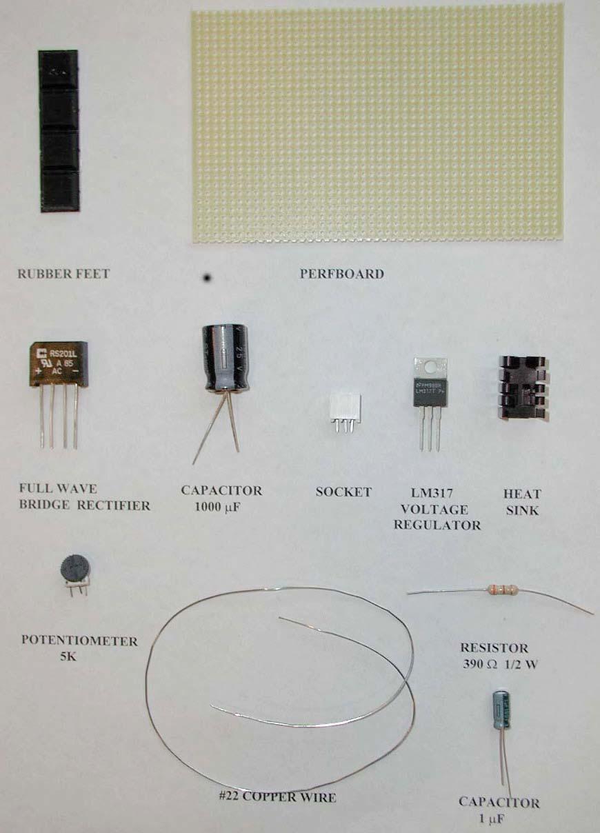
9 Figure 19: Wiring on bottom side of LVPS Construction Steps 1. Find and identify parts in the plastic bag. 2. Draw a line with a pen lengthwise along the center of the perfboard. 3. Stick 4 feet on the corners of the bottom side as close to the edge as possible. 4. Place the parts according to the top view of perfboard. Bend the white socket s short leads carefully while installing. (The black regulator s three leads will fit into the socket. You will only solder the socket s leads so that the regulator can be easily removed). Identify on your perfboard which socket leads will correspond to the ADJ, OUT, and IN leads of the regulator. 5. Bend the leads of the rectifier, capacitors, and resistors as shown on the bottom view of perfboard. 6. Measure, cut, and solder a piece of the bare #22 wire to the minus lead (-) of the rectifier. Extend this wire across the board, and then form a loop on the top side. This will be the minus (-) output loop. 9
10 7. Loop the end of the minus lead (-) of the large capacitor (the band points to the minus lead) through the perfboard at the bare wire from step 6. (This will help hold the capacitor to the perfboard). Solder the minus lead (-) of the large capacitor to the bare wire from step Solder the pot lead nearest the edge of the perfboard to the bare wire of step 6. Be sure the pot is oriented as shown in the top view. 9. Solder the minus lead (-) of the small capacitor (the band points to the minus lead) the bare wire of step Solder the plus lead (+) of the rectifier to the plus lead (+) of the large capacitor. 11. Solder the plus lead (+) of the large capacitor to the IN lead of the socket. (See step 4). 12. Measure, cut, and solder another piece of the bare #22 wire to the OUT lead of the socket. Extend this wire across the perfboard, and then form a loop on the top side. This will be the plus (+) output loop. 13. Solder the plus lead (+) of the small capacitor to the bare wire of the previous step Solder one lead of the resistor to the bare wire of step Solder the other lead of the resistor to the two other leads of the pot, thus connecting those two leads of the pot together. 16. Measure, cut, and solder another piece of the bare #22 wire to the ADJ lead of the socket to either of the connected pot leads of the previous step Remove about 6 mm of the insulation from two different lengths, 50 mm and 100 mm (2in and 4 in ) of black stranded wire. Tin all four ends and solder one length to each of the ac leads of the rectifier. Trying out Your LVPS Do not plug in the LM317T regulator. You should have already soldered alligator clips to your transformer leads, multimeter leads, and made clip leads. Clip one of the wall transformer leads to one of the LVPS leads of step 17. Set the MMM to the 25DCV range. Connect the voltmeter across the 1000µF capacitor, red to the plus side and black to the minus side. Plug in the wall transformer. Now touch the second transformer lead to the other ac lead of the LVPS. There should be little or no spark and the meter should read about 17 V 18V. Transfer the voltmeter leads to the output loops. Place the regulator in the heat sink with its metal back covered by the heat sink. Now plug in the 10
 from the plastic bag labeled LVPST (LVPS Test Kit) as a load on the LVPS.")
11 regulator into the socket with the number LM317T facing the large capacitor. Turn the pot and the output should vary from about 1.2V to 15V or more. To make sure that your LVPS is working as it should, use the 1157 lamp (used as a rear brake light in a car) from the plastic bag labeled LVPST (LVPS Test Kit) as a load on the LVPS. This lamp has two filaments (tail and stop light) with nominal ratings of 8 watts and 27 watts respectively at an applied voltage of 12.6V. Figure 20: Lamp and socket One lead to each filament is connected to the brass shell and the other lead is connected to one of the two terminals (soldered bumps) on the base of the lamp. Plug the lamp into the socket provided in your Red Box. There are two black leads from the socket. In order to connect one of the filaments to the LVPS, use your clip lead to connect one of the black wires from the socket to one output of the LVPS. Use a second clip lead to connect the other output of the LVPS to anywhere on the socket. (This connects the LVPS to the brass shell of the lamp.) Identify the 8W filament (cold resistance about 2 ), either with your MMM on the RX1 range or by lighting it with the LVPS---it's the upper filament in the lamp. Parts List for LVPS LVPS 1 perfboard 4 rubber feet 1 full wave bridge rectifier 1 electrolytic capacitor, 1000µF 1 socket for LM317T regulator 1 potentiometer, 5k 1 electrolytic capacitor, 1µF 1 resistor, W 1 ft wire, #22 bare solid 1 voltage regulator LM317T 1 heat sink for LM317 regulator 11
12 LVPST 1 resistor, 2.4 2W 1 lamp #1157 automotive RED BOX 1 socket for 1157 lamp 12
13 13
14 Testing the LVPS Each of you has built a power supply that converts ac (alternating current) power at 120V (volt), at a frequency of 60 Hz (hertz = cycles/sec) from the wall outlet into dc (direct current) power with a voltage range from 1.2 V to about 17 V. When the output voltage without load (lamp) is set between 1.2V and about 12 V, the output voltage will not change appreciably if a load is then placed across it. You will find that range when you place the 8W (watt) filament of an 1157 lamp across the output of the LVPS. See Building the LVPS: Trying out your LVPS. Measurements and Data You can set your pot at ten different settings from lowest to highest output by turning the top of the pot either clockwise or counterclockwise (depending on how you wired the legs). Set the pot so the no load output voltage is minimium, 2V, 4V, 6 V, 8V, 10 V, 12 V, 14V, 16 V, and maximum. Use the accompanying table to record the results of your measurements. For each setting you will: 1. Measure the output voltage (no-load voltage) of the LVPS when the lamp is not connected; 2. Measure the output voltage (load voltage) of the LVPS when the lamp is connected across the output of the LVPS. 3. Then connect the lamp and measure the load voltage across the terminals of the LVPS. Questions 1. What range of no-load output voltages remains unchanged after the lamp is connected across the LVPS output terminals? 2. Briefly describe how you distinguished between the 8W filament and the 27W filament? 3. What happens when you connect the outputs of the LVPS to the two black wires in the socket? Can you figure out the wiring diagram for the lamp? Graph Plot the output voltage of the LVPS without the lamp connected along the horizontal axis and the output voltage of the LVPS with the lamp connected along the vertical axis. 14
15 Data Table for LVPS Pot Setting minimum maximum V LVPS (no load) [volts] V LVPS (load) [volts] 15
Exercise MM About the Multimeter
 Exercise MM About the Multimeter Introduction Our world is filled with devices that contain electrical circuits in which various voltage sources cause currents to flow. Electrical currents generate heat,
Electricity and Magnetism Experiments from Kits
 Electricity and Magnetism Experiments from Kits Peter Dourmashkin John G. King Electricity and Magnetism Experiments from Kits Peter Dourmashkin Senior Lecturer in Physics Massachusetts Institute of Technology
Module 1, Lesson 2 Introduction to electricity. Student. 45 minutes
 Module 1, Lesson 2 Introduction to electricity 45 minutes Student Purpose of this lesson Explanations of fundamental quantities of electrical circuits, including voltage, current and resistance. Use a
Electrical Measurements
 Electrical Measurements INTRODUCTION In this section, electrical measurements will be discussed. This will be done by using simple experiments that introduce a DC power supply, a multimeter, and a simplified
AC/DC ELECTRONICS LABORATORY
 Includes Teacher's Notes and Typical Experiment Results Instruction Manual and Experiment Guide for the PASCO scientific Model EM-8656 012-05892A 1/96 AC/DC ELECTRONICS LABORATORY 1995 PASCO scientific
Pre-Laboratory Assignment
 Measurement of Electrical Resistance and Ohm's Law PreLaboratory Assignment Read carefully the entire description of the laboratory and answer the following questions based upon the material contained
Building the Toothpick Audio CW Filter
 Building the Toothpick Audio CW Filter Introduction The toothpick is a simple variable bandpass audio filter designed to compliment the Splinter QRPp Trans-Receiver. The filter also contains an audio amplifier
UNIVERSITY OF NORTH CAROLINA AT CHARLOTTE Department of Electrical and Computer Engineering
 UNIVERSITY OF NORTH CAROLINA AT CHARLOTTE Department of Electrical and Computer Engineering EXPERIMENT 2 BASIC CIRCUIT ELEMENTS OBJECTIVES The purpose of this experiment is to familiarize the student with
Building the Sawdust Regenerative Receiver
 Building the Sawdust Regenerative Receiver Introduction The Sawdust is a super regenerative receiver using the basic Armstrong design architecture. The receiver uses one toroidal transformer to provide
Bitx Version 3 Linear Amplifier Assembly
 Bitx Version 3 Linear Amplifier Assembly The power supply section has 2 options. 1 - AC input and a higher voltage on the IRF510 and +12 volts to the bitx. 2 - +12 volts applied to both the final and the
POWER SUPPLY MODEL XP-720. Instruction Manual ELENCO
 POWER SUPPLY MODEL XP-720 Instruction Manual ELENCO Copyright 2016, 1997 by ELENCO Electronics, Inc. All rights reserved. Revised 2016 REV-H 753270 No part of this book shall be reproduced by any means;
Electrical Fundamentals and Basic Components Chapters T2, T3, G4
 Electrical Fundamentals and Basic Components Chapters T2, T3, G4 Some Basic Math, Electrical Fundamentals, AC Power, The Basics of Basic Components, A Little More Component Detail, Reactance and Impedance
Experiment 8: An AC Circuit
 Experiment 8: An AC Circuit PART ONE: AC Voltages. Set up this circuit. Use R = 500 Ω, L = 5.0 mh and C =.01 μf. A signal generator built into the interface provides the emf to run the circuit from Output
IPR LA-3 KIT last update 15 march 06
 IPR LA-3 KIT last update 15 march 06 PART-2: Audio Circuitry CIRCUIT BOARD LAYOUT: Power and Ground Distribution Now that your power supply is functional, it s time to think about how that power will be
Current, resistance, and Ohm s law
 Current, resistance, and Ohm s law Apparatus DC voltage source set of alligator clips 2 pairs of red and black banana clips 3 round bulb 2 bulb sockets 2 battery holders or 1 two-battery holder 2 1.5V
transformer rectifiers
 Power supply mini-project This week, we finish up 201 lab with a short mini-project. We will build a bipolar power supply and use it to power a simple amplifier circuit. 1. power supply block diagram Figure
Group: Names: Resistor Band Colors Measured Value ( ) R 1 : 1k R 2 : 1k R 3 : 2k R 4 : 1M R 5 : 1M
 R 1 : 1k R 2 : 1k R 3 : 2k R 4 : 1M R 5 : 1M") 2.4 Laboratory Procedure / Summary Sheet Group: Names: (1) Select five separate resistors whose nominal values are listed below. Record the band colors for each resistor in the table below. Then connect
2.4 Laboratory Procedure / Summary Sheet Group: Names: (1) Select five separate resistors whose nominal values are listed below. Record the band colors for each resistor in the table below. Then connect
Physics 310 Lab 4 Transformers, Diodes, & Power Supplies
 Physics 310 Lab 4 Transformers, Diodes, & Power Supplies Equipment: O scope, W02G Bridge Rectifier, 110 6.3V transformer, four 1N4004 diodes, 1k, 10µF, 100µF, 1N5231 Zeener diode, ½ - Watt 100 Ω, 270Ω,
30 Watt Audio Power Amplifier
 30 Watt Audio Power Amplifier Including Preamp, Tone Controls, Reg dc Power Supply, 18 Watt into 8 Ohm - 30W into 4 Ohm loads Amplifier Section Circuit diagram: Audio Power Amplifier Circuit Diagram This
Building the Sawdust Regenerative Receiver
 Building the Sawdust Regenerative Receiver Introduction The Sawdust is a super regenerative receiver using the basic Armstrong design architecture. The receiver uses one toroidal transformer to provide
DC Circuits, Ohm's Law and Multimeters Physics 246
 DC Circuits, Ohm's Law and Multimeters Physics 246 Theory: In this lab we will learn the use of multimeters, verify Ohm s law, and study series and parallel combinations of resistors and capacitors. For
2.0 AC CIRCUITS 2.1 AC VOLTAGE AND CURRENT CALCULATIONS. ECE 4501 Power Systems Laboratory Manual Rev OBJECTIVE
 2.0 AC CIRCUITS 2.1 AC VOLTAGE AND CURRENT CALCULATIONS 2.1.1 OBJECTIVE To study sinusoidal voltages and currents in order to understand frequency, period, effective value, instantaneous power and average
University of Jordan School of Engineering Electrical Engineering Department. EE 204 Electrical Engineering Lab
 University of Jordan School of Engineering Electrical Engineering Department EE 204 Electrical Engineering Lab EXPERIMENT 1 MEASUREMENT DEVICES Prepared by: Prof. Mohammed Hawa EXPERIMENT 1 MEASUREMENT
LAB MODULES. MSCI 222C Introduction to Electronics. Charles Rubenstein, Ph. D. Professor of Engineering & Information Science
 MSCI 222C Introduction to Electronics Charles Rubenstein, Ph. D. Professor of Engineering & Information Science LAB MODULES Copyright 2015-2019 C.P.Rubenstein Electronics Hands-On Lab - Module 01 MSCI
EXPERIMENT 5 : DIODES AND RECTIFICATION
 EXPERIMENT 5 : DIODES AND RECTIFICATION Component List Resistors, one of each o 2 1010W o 1 1k o 1 10k 4 1N4004 (Imax = 1A, PIV = 400V) Diodes Center tap transformer (35.6Vpp, 12.6 VRMS) 100 F Electrolytic
Central Electronics Model 600L Linear Amplifier
 INTRODUCTION This manual has been reproduced by James Lawrence, NA5RC, a 600L owner. Text no longer applicable such as insurance claim with the carrier has been deleted. Some capitalization and grammar
ECE 2006 University of Minnesota Duluth Lab 11. AC Circuits
 1. Objective AC Circuits In this lab, the student will study sinusoidal voltages and currents in order to understand frequency, period, effective value, instantaneous power and average power. Also, the
EGR Laboratory 1 - Introduction to Circuit Analysis
 EGR 215 Laboratory 1 Introduction to Circuit Analysis Authors D. Wilson, R.D. Christie, W.R. Lynes, K.F. Böhringer, M. Ostendorf of the University of Washington Objectives At the end of this lab, you will
PHYSICS 221 LAB #6: CAPACITORS AND AC CIRCUITS
 Name: Partners: PHYSICS 221 LAB #6: CAPACITORS AND AC CIRCUITS The electricity produced for use in homes and industry is made by rotating coils of wire in a magnetic field, which results in alternating
Industrial Electricity. Answer questions and/or record measurements in the spaces provided.
 Industrial Electricity Lab 10: Building a Basic Power Supply ame Due Friday, 3/16/18 Answer questions and/or record measurements in the spaces provided. Measure resistance (impedance actually) on each
EXAMPLE. Use this jack for the red test lead when measuring. current from 0 to 200mA. Figure P-1
 Digital Multimeters ON / OFF power switch Continuity / Diode Test Function Resistance Function Ranges from 200Ω to 200MΩ Transistor Test Function DC Current Function Ranges from 2mA to 20A. AC Current
EXPERIMENT 5 : THE DIODE
 EXPERIMENT 5 : THE DIODE Component List Resistors, one of each o 1 10 10W o 1 1k o 1 10k 4 1N4004 (Imax = 1A, PIV = 400V) Diodes Center tap transformer (35.6Vpp, 12.6 VRMS) 100 F Electrolytic Capacitor
11. AC-resistances of capacitor and inductors: Reactances.
 11. AC-resistances of capacitor and inductors: Reactances. Purpose: To study the behavior of the AC voltage signals across elements in a simple series connection of a resistor with an inductor and with
Digital Electronics & Chip Design
 Digital Electronics & Chip Design Lab Manual I: The Utility Board 1999 David Harris The objective of this lab is to assemble your utility board. This board, containing LED displays, switches, and a clock,
Physics 3330 Experiment #2 Fall DC techniques, dividers, and bridges
 Physics 3330 Experiment #2 Fall 2002 DC techniques, dividers, and bridges Purpose You will gain a familiarity with the circuit board and work with a variety of DC techniques, including voltage dividers,
Experiment P45: LRC Circuit (Power Amplifier, Voltage Sensor)
") PASCO scientific Vol. 2 Physics Lab Manual: P45-1 Experiment P45: (Power Amplifier, Voltage Sensor) Concept Time SW Interface Macintosh file Windows file circuits 30 m 700 P45 P45_LRCC.SWS EQUIPMENT NEEDED
PASCO scientific Vol. 2 Physics Lab Manual: P45-1 Experiment P45: (Power Amplifier, Voltage Sensor) Concept Time SW Interface Macintosh file Windows file circuits 30 m 700 P45 P45_LRCC.SWS EQUIPMENT NEEDED
DIGITAL / ANALOG TRAINER
 DIGITAL / ANALOG TRAINER MODEL XK-150 A COMPLETE MINI-LAB FOR BUILDING, TESTING AND PROTOTYPING ANALOG AND DIGITAL CIRCUITS Instruction Manual ELENCO Copyright 2016, 1998 by ELENCO Electronics, Inc. All
HANDS-ON LAB INSTRUCTION SHEETS MODULE
 HANDS-ON LAB INSTRUCTION SHEETS MODULE 1 MEASURING RESISTANCE AND VOLTAGE NOTES: 1) Each student will be assigned to a unique Lab Equipment number MS01-MS30 which will match to a Tool Kit and a Radio Shack
For the filter shown (suitable for bandpass audio use) with bandwidth B and center frequency f, and gain A:
 with bandwidth B and center frequency f, and gain A:") Basic Op Amps The operational amplifier (Op Amp) is useful for a wide variety of applications. In the previous part of this article basic theory and a few elementary circuits were discussed. In order to
Basic Op Amps The operational amplifier (Op Amp) is useful for a wide variety of applications. In the previous part of this article basic theory and a few elementary circuits were discussed. In order to
Read This Page First
 Read This Page First If you are reading this you know the manuals are always available at QRPKITS.com. This is version 8.0 of the manual dated 4/27/2016. There is no need to print out the whole assembly
Wiring Manual NEScaf April 2010 (August 2006)
") Wiring Manual NEScaf April 2010 (August 2006) Switched Capacitor Audio Filter The NEScaf is a switched capacitor audio filter (acronym SCAF) built around a building-block type filter chip. The NEScaf will
Wiring Manual NEScaf April 2010 (August 2006) Switched Capacitor Audio Filter The NEScaf is a switched capacitor audio filter (acronym SCAF) built around a building-block type filter chip. The NEScaf will
EXPERIMENT 5 : THE DIODE
 EXPERIMENT 5 : THE DIODE Component List Resistors, one of each o 1 10 10W o 1 1k o 1 10k 4 1N4004 (I max = 1A, PIV = 400V) Diodes Center tap transformer (35.6V pp, 12.6 V RMS ) 100 F Electrolytic Capacitor
Laboratory 1 page 1 of 13
 Laboratory 1 page 1 of 13 Laboratory 1 Using the Meter, Breadboard, and Soldering Iron Introduction Welcome to the Bio Electronics Laboratory (BEL) located in B10 Benedum Hall. In this first lab assignment,
VCE VET INTEGRATED TECHNOLOGIES
 Victorian Certificate of Education 2015 SUPERVISOR TO ATTACH PROCESSING LABEL HERE Letter STUDENT NUMBER VCE VET INTEGRATED TECHNOLOGIES Written examination Monday 9 November 2015 Reading time: 9.00 am
LAB 1: Familiarity with Laboratory Equipment (_/10)
") LAB 1: Familiarity with Laboratory Equipment (_/10) PURPOSE o gain familiarity with basic laboratory equipment oscilloscope, oscillator, multimeter and electronic components. EQUIPMEN (i) Oscilloscope
LAB 1: Familiarity with Laboratory Equipment (_/10) PURPOSE o gain familiarity with basic laboratory equipment oscilloscope, oscillator, multimeter and electronic components. EQUIPMEN (i) Oscilloscope
Lab E2: B-field of a Solenoid. In the case that the B-field is uniform and perpendicular to the area, (1) reduces to
 reduces to") E2.1 Lab E2: B-field of a Solenoid In this lab, we will explore the magnetic field created by a solenoid. First, we must review some basic electromagnetic theory. The magnetic flux over some area A is
E2.1 Lab E2: B-field of a Solenoid In this lab, we will explore the magnetic field created by a solenoid. First, we must review some basic electromagnetic theory. The magnetic flux over some area A is
Definitions of Technical Terms
 Definitions of Technical Terms Terms Ammeter Amperes, Amps Band Capacitor Carrier Squelch Diode Dipole Definitions How is an ammeter usually connected = In series with the circuit What instrument is used
A 100-Watt Transmitter Using a Pair of VT1625s
 12/16/2007 6:00 PM VT1625 100 Watt Transmitter A 100-Watt Transmitter Using a Pair of VT1625s FIG. 10.6 A 100-watt transmitter for five bands, using salvaged TV power transformer and surplus 1625 amplifier
Physics 1051 Laboratory #4 DC Circuits and Ohm s Law. DC Circuits and Ohm s Law
 DC Circuits and Ohm s Law Contents Part I: Objective Part II: Introduction Part III: Apparatus and Setup Part IV: Measurements Part V: Analysis Part VI: Summary and Conclusions Part I: Objective In this
LM150/LM350A/LM350 3-Amp Adjustable Regulators
 LM150/LM350A/LM350 3-Amp Adjustable Regulators General Description The LM150 series of adjustable 3-terminal positive voltage regulators is capable of supplying in excess of 3A over a 1.2V to 33V output
PM124 Installation Instructions. See important note about revisions of this board on the last page.
 Marchand Electronics Inc. PO Box 473, Webster, NY 14580 Tel:(716) 872-0980 Fax:(716) 872-1960 info@marchandelec.com http://www.marchandelec.com (c)1997 Marchand Electronics Inc. PM124 Installation Instructions
Resistance and Ohm s law
 Resistance and Ohm s law Objectives Characterize materials as conductors or insulators based on their electrical properties. State and apply Ohm s law to calculate current, voltage or resistance in an
Experiment P49: Transistor Lab 2 Current Gain: The NPN Emitter-Follower Amplifier (Power Amplifier, Voltage Sensor)
") PASCO scientific Vol. 2 Physics Lab Manual: P49-1 Experiment P49: Transistor Lab 2 Current Gain: The NPN Emitter-Follower Amplifier (Power Amplifier, Voltage Sensor) Concept Time SW Interface Macintosh
PASCO scientific Vol. 2 Physics Lab Manual: P49-1 Experiment P49: Transistor Lab 2 Current Gain: The NPN Emitter-Follower Amplifier (Power Amplifier, Voltage Sensor) Concept Time SW Interface Macintosh
Value Location Qty Transistors 2N5485 Q1, Q2, 4 Q3, Q4 2N5087 Q5 1. Trim Pots 250k VTRIM 1. Potentiometers C500k Speed 1. Toggle Switch On/On Vibe 1
 P-90 BUILD INSTRUCTIONS Thank you for your purchase of our P-90 kit! We have completely redesigned our entire line of kits to be the most user friendly, while still maintaining their same great sound!
PHYSICS 171 UNIVERSITY PHYSICS LAB II. Experiment 4. Alternating Current Measurement
 PHYSICS 171 UNIVERSITY PHYSICS LAB II Experiment 4 Alternating Current Measurement Equipment: Supplies: Oscilloscope, Function Generator. Filament Transformer. A sine wave A.C. signal has three basic properties:
AME140 Lab #2 INTRODUCTION TO ELECTRONIC TEST EQUIPMENT AND BASIC ELECTRONICS MEASUREMENTS
 INTRODUCTION TO ELECTRONIC TEST EQUIPMENT AND BASIC ELECTRONICS MEASUREMENTS The purpose of this document is to guide students through a few simple activities to increase familiarity with basic electronics
Q2. Figure 1 shows the oscilloscope trace an alternating current (a.c.) electricity supply produces.
 electricity supply produces.") SERIES AND PARALEL CIRCUITS Q1. A student set up the electrical circuit shown in the figure below. (a) The ammeter displays a reading of 0.10 A. Calculate the potential difference across the 45 Ω resistor.
SERIES AND PARALEL CIRCUITS Q1. A student set up the electrical circuit shown in the figure below. (a) The ammeter displays a reading of 0.10 A. Calculate the potential difference across the 45 Ω resistor.
Electricity Transition Questions Applied General in Science
 Electricity Transition Questions Applied General in Science Marks: 62 marks Pass = 30% Comments: Merit = 45% Distinction = 65% Name: Teacher: MDS Date: Q1. (a) Draw one line from each circuit symbol to
EXPERIMENT 5 : THE DIODE
 EXPERIMENT 5 : THE DIODE Equipment List Dual Channel Oscilloscope R, 330, 1k, 10k resistors P, Tri-Power Supply V, 2x Multimeters D, 4x 1N4004: I max = 1A, PIV = 400V Silicon Diode P 2 35.6V pp (12.6 V
STEP 0 Prepare the Materials.
 How to Build a Germanium Fuzz Guitar Effect. This document will guide you to build and test your Germanium Fuzz guitar pedal. With all the materials on hand, it takes around 2-4 hours to build it. Try
PM24 Installation Instructions
 Marchand Electronics Inc. PO Box 473, Webster, NY 14580 Tel:(716) 872-0980 Fax:(716) 872-1960 info@marchandelec.com http://www.marchandelec.com (c)1997 Marchand Electronics Inc. PM24 Installation Instructions
ECE 201 LAB 8 TRANSFORMERS & SINUSOIDAL STEADY STATE ANALYSIS
 Version 1.1 1 of 8 ECE 201 LAB 8 TRANSFORMERS & SINUSOIDAL STEADY STATE ANALYSIS BEFORE YOU BEGIN PREREQUISITE LABS Introduction to MATLAB Introduction to Lab Equipment Introduction to Oscilloscope Capacitors,
B EE Laboratory 1 - Introduction to Circuit Analysis
 Page 1 B EE 215 Introduction to Circuit Analysis Authors D. Wilson, R.D. Christie, W.R. Lynes, K.F. Böhringer, M. Ostendorf Objectives At the end of this lab, you will be able to: Check continuity with
29:128 Homework Problems
 29:128 Homework Problems Revised 22 Feb 2012 29:128 Homework 1 (15 points) references: Sections 1.6-1.7 & 4.8, Meyer Chapter 1 of Horowitz and Hill, 2nd Edition (1) In the circuit shown below, V in = 9
+ 24V 3.3K - 1.5M. figure 01
 ELECTRICITY ASSESSMENT 35 questions Revised: 08 Jul 2013 1. Which of the wire sizes listed below results in the least voltage drop in a circuit carrying 10 amps: a. 16 AWG b. 14 AWG c. 18 AWG d. 250 kcmil
Block diagram of Basic Three Terminal IC Regulator The figure shows the functional block diagram of basic three terminal IC regulator.
 Three Terminal Fixed Voltage Regulators As the name suggests, three terminal voltage regulators have three terminals namely input which is unregulated (V in ), regulated output (V o ) and common or a ground
AC Theory and Electronics
 AC Theory and Electronics An Alternating Current (AC) or Voltage is one whose amplitude is not constant, but varies with time about some mean position (value). Some examples of AC variation are shown below:
MASSACHUSETTS INSTITUTE OF TECHNOLOGY
 Name: MASSACHUSETTS INSTITUTE OF TECHNOLOGY 6.091 Hands-On Introduction to EE Lab Skills Laboratory No. 1 Oscilloscopes, Multimeter, Function Generator IAP 2008 1 Objective In this laboratory, you will
PHYS 1402 General Physics II Experiment 5: Ohm s Law
 PHYS 1402 General Physics II Experiment 5: Ohm s Law Student Name Objective: To investigate the relationship between current and resistance for ordinary conductors known as ohmic conductors. Theory: For
The Wave (K-MOD103) GUITAR DWELL REVERB REVERB SWITCH ON OUT OFF
 GUITAR DWELL REVERB REVERB SWITCH ON OUT OFF") The Wave (K-MOD103) OUT IN GUITAR IN DWELL REVERB REVERB SWITCH ON GUITAR OUT POWER ON OFF OFF Please note, there are no labels for this kit. The controls, switches and connectors have only been labeled
The Wave (K-MOD103) OUT IN GUITAR IN DWELL REVERB REVERB SWITCH ON GUITAR OUT POWER ON OFF OFF Please note, there are no labels for this kit. The controls, switches and connectors have only been labeled
Experiment #2 Half Wave Rectifier
 PURPOSE: ELECTRONICS 224 ETR620S Experiment #2 Half Wave Rectifier This laboratory session acquaints you with the operation of a diode power supply. You will study the operation of half-wave and the effect
Experiment 1: Instrument Familiarization (8/28/06)
") Electrical Measurement Issues Experiment 1: Instrument Familiarization (8/28/06) Electrical measurements are only as meaningful as the quality of the measurement techniques and the instrumentation applied
Electrical Measurement Issues Experiment 1: Instrument Familiarization (8/28/06) Electrical measurements are only as meaningful as the quality of the measurement techniques and the instrumentation applied
PowerAmp Design. PowerAmp Design PAD541 COMPACT POWER OP AMP
 PowerAmp Design COMPACT POWER OP AMP Rev E KEY FEATURES LOW COST HIGH VOLTAGE 00 VOLTS HIGH OUTPUT CURRENT 5 AMPS 50 WATT DISSIPATION CAPABILITY 00 WATT OUTPUT CAPABILITY 0.63 HEIGHT SIP DESIGN APPLICATIONS
HANDS-ON LAB INSTRUCTION SHEET MODULE 3 CAPACITORS, TIME CONSTANTS AND TRANSISTOR GAIN
 HANDS-ON LAB INSTRUCTION SHEET MODULE 3 CAPACITORS, TIME CONSTANTS AND TRANSISTOR GAIN NOTES: 1) To conserve the life of the Multimeter s 9 volt battery, be sure to turn the meter off if not in use for
Equipment and materials to be checked out from stockroom: ECE 2210 kit, optional, if available. Analog BK precision multimeter or similar.
 p1 ECE 2210 Capacitors Lab University of Utah Electrical & Computer Engineering Department ECE 2210/2200 Lab 5 Capacitors A. Stolp, 10/4/99 rev 9/23/08 Objectives 1.) Observe charging and discharging of
Experiment 1: Circuits Experiment Board
 01205892C AC/DC Electronics Laboratory Experiment 1: Circuits Experiment Board EQUIPMENT NEEDED: AC/DC Electronics Lab Board: Wire Leads Dcell Battery Graph Paper Purpose The purpose of this lab is to
Experiment 3. Ohm s Law. Become familiar with the use of a digital voltmeter and a digital ammeter to measure DC voltage and current.
 Experiment 3 Ohm s Law 3.1 Objectives Become familiar with the use of a digital voltmeter and a digital ammeter to measure DC voltage and current. Construct a circuit using resistors, wires and a breadboard
DLVP A OPERATOR S MANUAL
 DLVP-50-300-3000A OPERATOR S MANUAL DYNALOAD DIVISION 36 NEWBURGH RD. HACKETTSTOWN, NJ 07840 PHONE (908) 850-5088 FAX (908) 908-0679 TABLE OF CONTENTS INTRODUCTION...3 SPECIFICATIONS...5 MODE SELECTOR
Testing Power Factor Correction Circuits For Stability
 Keywords Venable, frequency response analyzer, impedance, injection transformer, oscillator, feedback loop, Bode Plot, power supply design, switching power supply, PFC, boost converter, flyback converter,
ECE 2274 Lab 2. Your calculator will have a setting that will automatically generate the correct format.
 ECE 2274 Lab 2 Forward (DO NOT TURN IN) You are expected to use engineering exponents for all answers (p,n,µ,m, N/A, k, M, G) and to give each with a precision between one and three leading digits and
CHAPTER 5 CONCEPTS OF ALTERNATING CURRENT
 CHAPTER 5 CONCEPTS OF ALTERNATING CURRENT INTRODUCTION Thus far this text has dealt with direct current (DC); that is, current that does not change direction. However, a coil rotating in a magnetic field
UNIVERSITY OF UTAH ELECTRICAL ENGINEERING DEPARTMENT
 UNIVERSITY OF UTAH ELECTRICAL ENGINEERING DEPARTMENT ECE 3110 LAB EXPERIMENT NO. 4 CLASS AB POWER OUTPUT STAGE Objective: In this laboratory exercise you will build and characterize a class AB power output
Experiment 2. Ohm s Law. Become familiar with the use of a digital voltmeter and a digital ammeter to measure DC voltage and current.
 Experiment 2 Ohm s Law 2.1 Objectives Become familiar with the use of a digital voltmeter and a digital ammeter to measure DC voltage and current. Construct a circuit using resistors, wires and a breadboard
Dev Bhoomi Institute Of Technology Department of Electronics and Communication Engineering PRACTICAL INSTRUCTION SHEET
 Dev Bhoomi Institute Of Technology Department of Electronics and Communication Engineering PRACTICAL INSTRUCTION SHEET LABORATORY MANUAL EXPERIMENT NO. ISSUE NO. : ISSUE DATE: REV. NO. : REV. DATE : PAGE:
Assembly Instructions: Kit #5
 Assembly Instructions: Kit #5 1. Insert the T-pin into one of the caps. 2. Insert the rotor core into the same cap as shown below. Apply some pressure to push the rotor core approximately 1/2" (10-12 mm)
MICROGRANNY v2.1 - Assembly Guide
 last update: 9. 5. 2017 MICROGRANNY v2.1 - Assembly Guide bastl-instruments.com INTRODUCTION Welcome to the assembly guide for the MicroGranny kit. MicroGranny is a monophonic granular sampler by Bastl
LITTLE NERD v1.1 Assembly Guide
 last update: 9. 3. 2016 LITTLE NERD v1.1 Assembly Guide bastl instruments.com INTRODUCTION This guide is for building Little Nerd module from Bastl Instruments. It is good to have basic soldering skills
LM117/LM317A/LM317 3-Terminal Adjustable Regulator
 LM117/LM317A/LM317 3-Terminal Adjustable Regulator General Description Typical Applications The LM117 series of adjustable 3-terminal positive voltage regulators is capable of supplying in excess of 1.5A
BME/ISE 3512 Laboratory - Three Diode (1N4001)
") BME/ISE 3512 Laboratory Three Diode (1N4001) Learning Objectives: Understand the concept of PN junction diodes, their application as rectifiers, the nature and application of halfwave and fullwave rectifiers,
BME/ISE 3512 Laboratory Three Diode (1N4001) Learning Objectives: Understand the concept of PN junction diodes, their application as rectifiers, the nature and application of halfwave and fullwave rectifiers,
VISUAL PHYSICS ONLINE. Experiment PA41A ELECTRIC CIRCUITS
 VISUAL PHYSICS ONLINE Experiment PA41A ELECTRIC CIRCUITS Equipment (see Appendices) 12V DC power supply (battery): multimeter (and/or milliammeter and voltmeter); electrical leads; alligator clips; fixed
Physics of Music Projects Final Report
 Physics of Music Projects Final Report Kyle Kleyweg Prof. Steven Errede PHYS498 POM May 12, 2011 1 Abstract The following project was begun in the spring of 2011 in an attempt to create plasma speakers
Experiment 1: Instrument Familiarization
 Electrical Measurement Issues Experiment 1: Instrument Familiarization Electrical measurements are only as meaningful as the quality of the measurement techniques and the instrumentation applied to the
R 1 R 2. (3) Suppose you have two ac signals, which we ll call signals A and B, which have peak-to-peak amplitudes of 30 mv and 600 mv, respectively.
 Suppose you have two ac signals, which we ll call signals A and B, which have peak-to-peak amplitudes of 30 mv and 600 mv, respectively.") 29:128 Homework Problems 29:128 Homework 0 reference: Chapter 1 of Horowitz and Hill (1) In the circuit shown below, V in = 9 V, R 1 = 1.5 kω, R 2 = 5.6 kω, (a) Calculate V out (b) Calculate the power
29:128 Homework Problems 29:128 Homework 0 reference: Chapter 1 of Horowitz and Hill (1) In the circuit shown below, V in = 9 V, R 1 = 1.5 kω, R 2 = 5.6 kω, (a) Calculate V out (b) Calculate the power
LumiDax Electronics LLC Bakerboard Analog Trainer. Operator's Guide with Example Projects
 LumiDax Electronics LLC Bakerboard Analog Trainer Operator's Guide with Example Projects Written by Jonathan Baumgardner Copyright 2014 Introduction The LumiDax Bakerboard Analog Trainer is an all-in-one
ESE141 Circuit Board Instructions
 ESE141 Circuit Board Instructions Board Version 2.1 Fall 2006 Washington University Electrical Engineering Basics Because this class assumes no prior knowledge or skills in electrical engineering, electronics
LM117/LM317A/LM317 3-Terminal Adjustable Regulator
 LM117/LM317A/LM317 3-Terminal Adjustable Regulator General Description Typical Applications May 1997 The LM117 series of adjustable 3-terminal positive voltage regulators is capable of supplying in excess
SoftRock v6.0 Builder s Notes. May 22, 2006
 SoftRock v6.0 Builder s Notes May 22, 2006 Be sure to use a grounded tip soldering iron in building the v6.0 SoftRock circuit board. The soldering iron needs to have a small tip, (0.05-0.1 inch diameter),
PHYSICS FORM 5 ELECTRICITY
 Current Types of Current: 1. Conventional Current 2. Electric Current Conventional Current Long ago, it was believed that current was a flow of positive charges. The direction of conventional current therefore
Experiment P48: Transistor Lab 1 The NPN Transistor as a Digital Switch (Power Amplifier, Voltage Sensor)
") PASCO scientific Vol. 2 Physics Lab Manual: P48-1 Experiment P48: Transistor Lab 1 The NPN Transistor as a Digital Switch (Power Amplifier, Voltage Sensor) Concept Time SW Interface Macintosh file Windows
PASCO scientific Vol. 2 Physics Lab Manual: P48-1 Experiment P48: Transistor Lab 1 The NPN Transistor as a Digital Switch (Power Amplifier, Voltage Sensor) Concept Time SW Interface Macintosh file Windows
Construction notes for the symmetrical 400 watt amplifier
 Construction notes for the symmetrical 400 watt amplifier Introduction The symmetrical amplifier is an update of one of my designs, which appeared in the Australian electronics magazine Silicon Chip in