SCHEMATIC TACHO_O DIAG_O PWM_I X1.6 X1.5 X1.8 X1.7 GND R28 R27 R25 R26 DIAG LED1 TP:DIAG R18. 47k. 6k8 R19 R17. 6k8 OFF TP:PWM R23.
|
|
|
- Nathan Conley
- 6 years ago
- Views:
Transcription
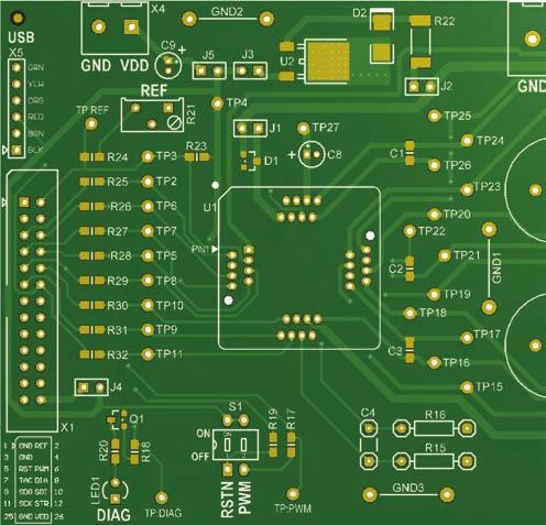
1 A4960 SCHEMATIC REF X5.4 R21 X5.3 50k X5.2 STRN_I X5.1 D TITLE: A4960 Customer Demonstration Board D (Ground Bars) USB REV: SIZE: Allegro Microsystems Inc 4 A3.5 AUTHOR: SHEET: Bob Christie 1 of 1 Worcester MA USA DATE: PCB: 16th Jun 2015 EDC058R4 SDO_O SDI_I SCK_I X5.6 X5.5 X5 R24 X1.1 X1.3 X U1 R16 TP:REF C4 1n 6.3V R7 0R010 2W R8 0R010 2W C 18 TP18 R5 M6 GHC C X1.12 R32 TP TP16 STRN_I STRN SC X1.11 R31 TP9 TP15 R6 SCK_I SCK GLC 15 R14 470k X1.10 R30 TP10 10 SDI_I SDI X1.9 R29 TP8 14 SDO_O SDO LSS R15 13 CSP X1.2 REF TP3 REF CSM 12 A DIAG_O X1.8 R28 TP5 DIAG CC 17 TP17 C3 220n 6.3V TACHO_O X1.7 R27 TP7 TACHO R4 R12 470k R13 470k PWM_I X1.6 R26 TP6 PWM 20 GHB 21 SB GLB 19 TP20 TP21 TP19 R3 220n 6.3V M4 M5 X3.1 C TP:PWM RESETN_I X1.5 R25 TP2 RESETN CB 22 TP22 C2 X3.2 B 4.7u 25V A4960 R2 R10 470k R11 470k TP:DIAG GHA 24 SA 25 GLA 23 R19 6k8 R17 6k8 R23 75k TP25 TP24 TP23 X3.3 A X3 R1 M3 100n 50V VREG + LED1 DIAG C8 TP27 27 CA 26 TP26 C1 220n 6.3V M2 R18 47k C6 R9 470k B BC857B B Q1 ON S1 1 2 R20 3k3 OFF TP4 VDD VBRG 1 M1 IRFR2405PBF VBB 32 CP1 CP VDDIF X n 25V X1 J4 RSTN PWM 100n 50V C11 C12 C13 100n 100n 100n C10 C5 680u 50V 50V 50V 50V + C14 680u 50V + (S1 text) J1 C7 D1 BAT54 + C9 10u 16V J5 J3 5V OUT IN 47R D2 BZG03C27 J2 MC78M05ABDTG U2 A R22 A X4.1 X4.2 X2.1 X2.2 X4 X2 VDD VBAT A4960-DB

2 LAYOUT 2
3 3
4 4
5 5
6 6
7 BILL OF MATERIALS Designator SIL Skt Value Rating Tol Part Number Footprint Description DNF Qty RS Farnell C1, C2, C3 \ 220n 6.3V X7R \ SM : 0805 Capacitor : Ceramic Chip \ \ C4 Skt 1n 6.3V X7R \ TH : 5mm Pitch [SKT] Capacitor : Dipped Ceramic Radial \ C5 \ 470n 25V X7R \ SM : 0805 Capacitor : Ceramic Chip \ \ C6, C7, C11, C12, C13 \ 100n 50V X7R \ SM : 0805 Capacitor : Ceramic Chip \ C8 \ 4.7u 25V 20% \ TH : 4mm Dia, 1.5mm Pitch Capacitor : Alu Electrolytic Radial \ \ C9 \ 10u 16V 20% \ TH : 4mm Dia, 1.5mm Pitch Capacitor : Alu Electrolytic Radial \ \ C10, C14 \ 680u 50V 20% \ TH : 16mm Dia, 5mm Pitch, 20mm H Capacitor : Alu Electrolytic Radial \ D1 \ \ \ \ BAT54 SM : SOT23 Diode : Schottky, 30V, 0.2A \ D2 \ \ \ \ BZG03C27 SM : DO214AC (SMA) Diode : Zener, 27V \ , 2, 3 \ \ \ \ \ TH : 12mm Pitch, 20swg Ground Bar : Tinned Copper Wire \ \ J1, J2, J3, J4, J5 \ \ \ \ \ TH : SIL2, 2.54mm Pitch, 1x2 Jumper Header : Male 2-pin \ \ LED1 \ \ \ \ \ TH : 3mm (T-1), 2.54mm Pitch LED : 3mm, Red \ \ M1, M2, M3, M4, M5, M6 \ \ \ \ IRFR2405PBF SM : TO-252 (DPAK) Mosfet : N Channel, 56A, 55V \ MF1, MF2, MF3, MF4, MF5 \ \ \ \ \ SM : 9.5mm Dia Mount Foot : Adhesive Rubber \ 5 \ PCB \ \ \ \ EDC058R4 FR4, 2oz Cu, 2 Layer PCB : A4960 Demo Board \ 1 \ \ Q1 \ \ \ \ BC857B SM : SOT23 Transistor : PNP, 65V, 0.1A \ R1, R2, R3, R4, R5, R6 \ 0.125W 1% \ SM : 0805 Resistor : Ceramic Chip \ \ R7, R8 \ 0R010 2W 1% \ SM : 2512 Resistor : Ceramic Chip \ \ R9, R10, R11, R12, R13, R14 \ 470k 0.125W 1% \ SM : 0805 Resistor : Ceramic Chip \ R15, R16 Skt 0.125W 1% \ TH : 10mm Pitch, 6mm Body [SKT] Resistor : Axial [SKT] \ \ R17, R19 \ 6k W 1% \ SM : 0805 Resistor : Ceramic Chip \ R18 \ 47k 0.125W 1% \ SM : 0805 Resistor : Ceramic Chip \ \ R20 \ 3k W 1% \ SM : 0805 Resistor : Ceramic Chip \ R21 \ 50k 0.5W 10% \ TH : 3pin, 2.54mm Pitch, 10x5mm Body Resistor : Trim Pot, 3296Y \ R22 \ 47R 1W 1% \ SM : 2512 Resistor : Ceramic Chip \ \ R23 \ 75k 0.125W 1% \ SM : 0805 Resistor : Ceramic Chip \ R24, R25, R26, R27, R28, R29, R30, R31, R32 \ 0.125W 1% \ SM : 0805 Resistor : Ceramic Chip \ S1 \ \ \ \ \ TH : 2.54mm (100mils) Pitch Switch : DIL, 2-way, Raised Actuator \ TP2, TP3, TP4, TP5, TP6, TP7, TP8, TP9, TP10, TP11, TP15, TP16, TP17, TP18, TP19, TP20, \ TP21, TP22, TP23, TP24, TP25, \ \ \ \ TH : 1mm Dia Hole Test Point : Test Terminal, 1mm, Red \ TP26, TP27, TP:DIAG, TP:PWM, TP:REF U1 (Socket) \ \ \ \ OTQ TH : LQFP32 skt Socket : Enplas (LQFP32) \ 1 \ \ U1 (Device) \ \ \ \ A4960 SM : elqfp32 Device : Allegro Motor Driver DNF 0 \ \ U2 \ \ \ \ MC78M05ABDTG SM : TO-252 (DPAK) Device : Voltage Regulator 5V \ X1 \ \ \ \ \ TH : 2.54mm Pitch, 2x13 Connector : IDC 26-way Ribbon Header \ X2 \ \ \ \ \ TH : 7.62mm (300mils) Pitch Screw Terminal : 2-way \ X3 \ \ \ \ \ TH : 7.62mm (300mils) Pitch Screw Terminal : 3-way \ X4 \ \ \ \ \ TH : 5.08mm (200mils) Pitch Screw Terminal : 2-way \ X5 \ \ \ \ \ TH : 2.54mm Pitch, 1x6, SIL6 Connector : 6-way Header Unshrouded \ [ESDBAG_6x10] \ \ \ \ \ \ ESD Bag : 152x254mm (6x10") \ [JMP_SHORT_R] \ \ \ \ \ \ Jumper Short/Shunt Link : Red \ [SIL_SKT] \ \ \ \ \ TH : SIL1 Socket : SIL1 (Parts = x3, Skts = x6) \ \ Note: "DNF" = "Do No Fit" (component not fitted). Note: An FTDi TTL-232R-5V USB cable will be required for SPI connection at X5 (& driver file & GUI file)
8 Revision History Number Date Description September 6, 2016 Initial release Copyright 2016, reserves the right to make, from time to time, such departures from the detail specifications as may be required to permit improvements in the performance, reliability, or manufacturability of its products. Before placing an order, the user is cautioned to verify that the information being relied upon is current. Allegro s products are not to be used in any devices or systems, including but not limited to life support devices or systems, in which a failure of Allegro s product can reasonably be expected to cause bodily harm. The information included herein is believed to be accurate and reliable. However, assumes no responsibility for its use; nor for any infringement of patents or other rights of third parties which may result from its use. For the latest version of this document, visit our website: 8
SCHEMATIC X4.1 X4.2 SPD VDD J6 PWM_OC PWM LED1 GND VSS PWM GND. PWM_Loc. GND 10u BS170G. STRn TP7 TP6 TP8 TP5 SCK SDI SDO SPD. STRn GND GND SPD.
 1 1 1 8 7 7 8 A9 SCHEMATIC Allegro Microsystems Inc Worcester MA 010 USA DATE: PCB: 17th Jul 01 EDC AUTHOR: Yi Li SHEET: 1 of 1 REV: SIZE: A. TITLE: D A9 Demonstration Board Rev D X.1 X. X. X. X. X. FTDI
Demo Board Schematic/Layout
 8 7 6 A9 SCHEMATIC A9-DB 0/0/0 :06:8 MICROSYSTEMS EUROPE LTD >SHEET: A A B C D E F G H 9Demo P Normally open link / / X- X- X- X- X- X-6 X-7 PHASEB PHASEA PHASEC X- X- X-6 CSOUT P P G G G6 G7 G8 These
A3930 and A3931. Demo Board Schematic/Layout SCHEMATIC A DB
 SCHEMATIC A3930-31-DB LAYOUT 2 3 4 BILL OF MATERIALS A3930/ Demo Board Rev 3 Component List Last Updated: 15/07/2014 Part Value Package Description RS Part Part Value Package Description RS Part C1 1000uF
SCHEMATIC X32.4 X32.3 STPS160A DV3 PGND DU1 IRF7749 DV2 X25 X24. Drain_V. Source_V. X29 & X30: VBAT out to "A6862 Demo Board" X4 & X10.
 SCHEMATIC 1 2 3 4 5 6 X32: Connects to "A6862 Demo Board" X3. Drain_U Connect to Bridge Drive. A X22 X32: Male header. A GU SU X32.2 X32.1 RU1 CU RU2 0R STPS160A DU3 DU1 MU IRF7749 DU2 X21 X23 Source_U
A4989. Demo Board Schematic/Layout. CONFIGURATION INFORMATION for the EDC023 demonstration circuit board
 CONFIGURATION INFORMATION for the EDC023 demonstration circuit board Thank you for choosing to evaluate this product. The following notes will help you to identify which version of the printed circuit
SCHEMATIC CN1 HC- HC+ HB- HB+ HA- HA+ PHA PHA VREF. Shunt VREF. 0.22uF VREF 8 HC- PHA HA- HC+ HB+ A SLUG OUTB GND. 10uF VBB PWM SEL FG JP2
 SCHEMATIC W W Allegro Logo Date: //0 Sheet of File: C:\altium\..\LPRev.SchDoc Drawn By: Bob Pickett A Size Number Revision 8-087-000-SCH Title D LP D Shunt SEL B SEL B PWMPin R k HA+ HA+ PWM/VSP PWM HA-
A Phase Sinusoidal Motor Controller. Description
 Features and Benefits Sinusoidal Drive Current Hall Element Inputs PWM Current Limiting Dead-time Protection FGO (Tach) Output Internal UVLO Thermal Shutdown Circuitry Packages: 32-Pin QFN (suffix ET)
A5957. Full-Bridge PWM Gate Driver PACKAGE:
 FEATURES AND BENEFITS PHASE/ENABLE/SLEEPn control logic Overcurrent indication Adjustable off-time and blank-time Adjustable current limit Adjustable gate drive Synchronous rectification Internal UVLO
A4950. Full-Bridge DMOS PWM Motor Driver. Description
 Features and Benefits Low R DS(on) outputs Overcurrent protection (OCP) Motor short protection Motor lead short to ground protection Motor lead short to battery protection Low Power Standby mode Adjustable
EVAL6235N. Demonstration board for L6235 DMOS driver for 3-phase brushless DC motor. Description. Features
 Demonstration board for L6235 DMOS driver for 3-phase brushless DC motor Description Data brief Features Operating supply voltage from 8 to 52 V 5.6 A output peak current (2.8 A DC) R DS(ON) 0.3 typ. value
TD99101 EVALUATION KIT USER S GUIDE. TD99101 Evaluation Kit. User's Guide March Teledyne e2v, Inc. All Rights Reserved
 User's Guide March 2018 TD99101 Evaluation Kit TD99101 EVALUATION KIT USER S GUIDE Information contained herein is classified as EAR99 under the U.S. Export Administration Regulations. Export, re-export
Discontinued Product
 Discontinued Product These parts are no longer in production The device should not be purchased for new design applications. Samples are no longer available. Date of status change: May 3, 2010 Recommended
A4970. Dual Full-Bridge PWM Motor Driver
 Dual Full-Bridge PWM Motor Driver Features and Benefits 750 ma continuous output current 45 V output sustaining voltage Internal clamp diodes Internal PWM current control Low output saturation voltage
Motor Control Development Kit
 User s Manual, V 1.0, June 2003 Motor Control Development Kit A reference design for low voltage 3-phase AC induction and brushless DC motor control. Microcontrollers Never stop thinking. Revision History:2003-06
A3949. DMOS Full-Bridge Motor Driver. Features and Benefits Single supply operation Very small outline package Low R DS(ON)
") Features and Benefits Single supply operation Very small outline package Low R DS(ON) outputs Sleep function Internal UVLO Crossover current protection Thermal shutdown protection Packages: Description
Features and Benefits Single supply operation Very small outline package Low R DS(ON) outputs Sleep function Internal UVLO Crossover current protection Thermal shutdown protection Packages: Description
MAX16818 Evaluation Kit. Evaluates: MAX16818
 9-08; Rev 0; 6/07 MAX688 Evaluation Kit General Description The MAX688 evaluation kit (EV kit) is a fully assembled and tested surface-mount printed-circuit board (PCB) designed to evaluate the MAX688
DISCONTINUED PRODUCT FOR REFERENCE ONLY. QUAD HIGH-CURRENT, HIGH-VOLTAGE SOURCE DRIVER FEATURES
 Data Sheet 29309.10 2944 V S Capable of driving loads to 4 A at supply voltages to 60 V (inductive loads to 35 V), the UDN2944W is a quad high-current, highvoltage source driver. Each of the four power
DUAL FULL-BRIDGE PWM MOTOR DRIVER
 96 Data Sheet 939.0L PWM OUT A OUT A E SENSE OUT B I 0 I PHASE V REF RC 3 4 5 6 8 9 0 UDN96B (DIP) θ PWM V BB PWM θ V CC 4 3 0 9 8 6 5 4 3 LOAD SUPPLY E SENSE OUT B I PHASE V REF RC LOGIC SUPPLY Dwg. PP-005
A8430. Approximate actual size. Same pad footprint as SOT-23-5 R θja = 50 C/W, see note 1, page 2 AB SO LUTE MAX I MUM RAT INGS
 MLPD Approximate actual size GND FB 1 2 3 4 AB SO LUTE MAX I MUM RAT INGS Pin... 0.3 V to 36 V Remaining Pins... 0.3 V to 10 V Ambient Operating Temperature, T A... 40 C to 8 C Junction Temperature, T
Servo and Motor Controller
 Servo and Motor Controller Date: August 0, 00 Description: The servo motor controller drives three R/C servomotors and one brushless DC motor. All four motors are controlled by PWM signals sent from a
Si4825-DEMO. Si4825 DEMO BOARD USER S GUIDE. 1. Features. Table 1. Si4825 Band Sequence Definition
 Si4825 DEMO BOARD USER S GUIDE 1. Features ATAD (analog tune and analog display) AM/FM/SW radio Worldwide FM band support 64 109 MHz with 18 bands, see the Table 1 Worldwide AM band support 504 1750 khz
Last Time Buy. Deadline for receipt of LAST TIME BUY orders: August 30, Recommended Substitutions: A3941KLPTR-T
 A3940 Full-Bridge Power MOSFET Controller Last Time Buy These parts are in production but has been determined to be LAST TIME BUY. This classification indicates that the product is obsolete and notice
PMD5003K. 1. Product profile. MOSFET driver. 1.1 General description. 1.2 Features. 1.3 Applications. Quick reference data
 Rev. 0 6 November 2006 Product data sheet. Product profile. General description PNP low V CEsat Breakthrough In Small Signal (BISS) transistor and high-speed switching diode to protect the base-emitter
IS31BL3230-QFLS2-EB QFN-16, Lead-free. Table1: Ordering Information
 IS3BL33 8 Channels Constant Current LED Driver Description The IS3BL33 provides eight regulated current sources; each delivers up to 4mA of load current with careful selection of external sense resistors,
Supertex inc. HV9971DB1. Isolated, Constant Current HV9971 LED Driver Demoboard. Board Layout and Connection Diagram.
 Isolated, Constant Current HV9971 LED Driver Demoboard Board Layout and Connection Diagram Terminals for Monitoring Bus Voltage - + V AC = + 180-265VAC = 18-24V - I OUT = 330mA Connections 1. Input Voltage:
A3901. Dual Full Bridge Low Voltage Motor Driver
 A39 Features and Benefits ow R DS(on) outputs Full- and half-stepping capability Small package Forward, reverse, and brake modes for DC motors Sleep mode with zero current drain PWM control up to 25 khz
A4941. Three-Phase Sensorless Fan Driver
 Features and Benefits Sensorless (no Hall sensors required) Soft switching for reduced audible noise Minimal external components PWM speed input FG speed output Low power standby mode Lock detection Optional
S U1 Configured for Filterless Output S U2 Configured for Filtered Output S Fully Assembled and Tested JU104, JU105, SHDN_1, TEMP_1
 9-5477; Rev 0; 8/0 MAX98400A Evaluation Kit General Description The MAX98400A evaluation kit (EV kit) configures the MAX98400A Class D amplifier to drive x0w into a pair of 8I speakers in stereo mode,
DESCRIPTION. Functional Block Diagram A4915 VBB. Charge Pump Regulator VREG. Bootstrap Monitor CA CB CC GHA GHB GHC SA SB SC C BOOTA.
 FEATURES AND BENEFITS 5 to 50 V supply voltage Latched TSD with fault output Drives six N-channel high current MOSFETs Internally controlled synchronous rectification Speed voltage input enables internal
HFRD REFERENCE DESIGN 2.5Gbps Cooled TOSA Evaluation Board. Reference Design: (Includes MAX3735A Laser Driver and MAX8521 TEC Controller)
") eference Design: HFD-21.0 ev. 4; 11/08 EFEENCE DESIGN 2.5Gbps Cooled TOSA Evaluation Board (Includes MAX3735A Laser Driver and MAX8521 TEC Controller) AVAILABLE eference Design: 2.5Gbps Cooled TOSA Evaluation
eference Design: HFD-21.0 ev. 4; 11/08 EFEENCE DESIGN 2.5Gbps Cooled TOSA Evaluation Board (Includes MAX3735A Laser Driver and MAX8521 TEC Controller) AVAILABLE eference Design: 2.5Gbps Cooled TOSA Evaluation
List of Items Available in the Laboratory the Lab
 List of Items Available in the Laboratory the Lab Category Component 555 Timer $0.30 5V Relay $3.50 74xxx Series IC Chip $0.30 Battery - 12V (rechargeable Lead-acid type) $16.00 Battery - 6V (rechargeable
Features. General Description. Component List
 MAX68 Evaluation Kit Evaluates: MAX68 General Description The MAX68 evaluation kit (EV kit) demonstrates the MAX68 high-brightness LED (HB LED) driver, integrating a step-up DC-DC preregulator followed
Driving 2W LEDs with ILD4120
 Application Note AN270 Revision: 0.4 Date: LED Driver & AF Discretes Edition 2011-09-13 Published by Infineon Technologies AG 81726 Munich, Germany 2011 Infineon Technologies AG All Rights Reserved. LEGAL
A5821. BiMOS II 8-Bit Serial Input Latched Driver. Discontinued Product
 A5821 BiMOS II 8-Bit Serial Input Latched Driver Discontinued Product These parts are no longer in production The device should not be purchased for new design applications. Samples are no longer available.
Protected Quad Power Driver
 Features and Benefits 700 ma output current per channel Independent overcurrent protection for each driver Thermal protection for device and each driver Low output-saturation voltage Integral output flyback
September 2012 Doc ID Rev 1 1/12
 High power stepper motor driver mounting the L6480 Data brief Features Voltage range from 0.5 V to 85 V Low R ds(on) MOSFETs in DPAK package SPI with daisy chain feature FLAG and BUSY LED indicators Adjustable
A4954 Dual Full-Bridge DMOS PWM Motor Driver
 Dual Full-Bridge DMOS Features and Benefits Low R DS(on) outputs Overcurrent protection (OCP) Motor short protection Motor lead short to ground protection Motor lead short to battery protection Low Power
Not for New Design. For existing customer transition, and for new customers or new applications,
 Not for New Design These parts are in production but have been determined to be NOT FOR NEW DESIGN. This classification indicates that sale of this device is currently restricted to existing customer applications.
Ocean Controls KT-5198 Dual Bidirectional DC Motor Speed Controller
 Ocean Controls KT-5198 Dual Bidirectional DC Motor Speed Controller Microcontroller Based Controls 2 DC Motors 0-5V Analog, 1-2mS pulse or Serial Inputs for Motor Speed 10KHz, 1.25KHz or 156Hz selectable
MAX16803EVKIT+BJT Evaluation Kit+
 19-0828; Rev 0; 5/07 MAX16803EVKIT+BJT Evaluation Kit+ General Description The MAX16803EVKIT+BJT (EV kit) demonstrates a high-current LED driver with accurate current control based on the MAX16803 current
MAX13487E Evaluation Kit. Evaluates: MAX13487E/MAX13488E. Features
 9-0; Rev ; /08 General Description The MAX87E evaluation kit (EV kit) is a fully assembled and tested PCB that contains a half-duplex RS- 85/RS- AutoDirection-controlled transceiver with ESD protection.
Discontinued Product
 Data Sheet 29319.4 NC REF/ BRAKE RC PHASE ENABLE 1 2 3 4 5 6 V CC ASB 7 10 8 9 ABSOLUTE MAXIMUM RATINGS Load Supply Voltage,... 50 V Output Current, I OUT (t w 20 µs)... ±3.5 A (Continuous)... ±2.0 A Logic
AMBIENT LIGHT DETECTOR
 LX1973A AMBIENT LIGHT DETECTOR TM Page 1 INTRODUCTION TO PRODUCT The LX1973A Evaluation Board is available from for evaluating the functionality and performance of the LX1973A ambient light sensor. The
A3921. Automotive Full Bridge MOSFET Driver
 Features and Benefits High current gate drive for N-channel MOSFET full bridge High-side or low-side PWM switching pump for low supply voltage operation Top-off charge pump for 100% PWM Cross-conduction
Discontinued Product
 Dual Full-Bridge PWM Motor Driver Discontinued Product This device is no longer in production. The device should not be purchased for new design applications. Samples are no longer available. Date of status
TP2 SWP 4.7 H. Designator LXP VOUTP NCP ENABLE J2 TP5 SWN FBN SWN D1 L2. R4 18k TP8 FBN. Figure 1. NCP5810DGEVB Schematic
 NCP580D: Dual W Output AMOLED Driver Supply Evaluation Board Prepared by: Hubert Grandry Overview The NCP580D is a dual output DC/DC converter which can generate both a positive and a negative voltage.
AN APPLICATION NOTE
 AN1894 - APPLICATION NOTE VIPower: VIPer12A NON ISOLATED BUCK AND BUCK-BOOST CONVERTER REFERENCE BOARD P. LIDAK - R. HAUSER ABSTRACT Presented circuit can be used to produce a single, non isolated positive
High Isolation, Nonreflective, GaAs, SPDT Switch,100 MHz to 4 GHz HMC349AMS8G
 Data Sheet High Isolation, Nonreflective, GaAs, SPDT Switch,1 MHz to 4 GHz FEATURES Nonreflective, 5 Ω design High isolation: 57 db to 2 GHz Low insertion loss:.9 db to 2 GHz High input linearity 1 db
Discontinued Product
 with Hall Commutation and Soft Switching, Discontinued Product This device is no longer in production. The device should not be purchased for new design applications. Samples are no longer available. Date
Supertex inc. HV9911DB2 Boost LED Driver Demoboard with 1:3000 Dimming Ratio and Excellent Current Regulation. Board Layout and Connection Diagram
 The is an LED driver capable of driving up to twenty 100mA LEDs in series from an input of 9-16V DC. The demoboard uses Supertex s HV9911 IC in a boost topology. The converter has a very good initial regulation,
ZLED7020KIT-D1 Demo Kit Description
 ZLED7020KIT-D Demo Kit Description Important Notice Restrictions in Use IDT s ZLED7020KIT-D Demo Kit hardware is designed for ZLED7020 demonstration, evaluation, laboratory setup, and module development
AMT Dual DMOS Full-Bridge Motor Driver PACKAGE: AMT49702 AMT49702
 FEATURES AND BENEFITS AEC-Q100 Grade 1 qualified Wide, 3.5 to 15 V input voltage operating range Dual DMOS full-bridges: drive two DC motors or one stepper motor Low R DS(ON) outputs Synchronous rectification
Universal, Off-Line, High Brightness, 350mA LED Driver Demo Board
 Universal, Off-Line, High Brightness, 30mA LED Driver Demo Board HV990BDB General Description The Supertex HV990BDB demo board is a High- Brightness LED power driver to supply a string of LEDs using the
A8431. White LED Driver Constant Current Step-up Converter
 Features and Benefits Output voltage up to 32 V ( level) 2. to 0 V input Drives up to 4 LEDs at 20 ma from a 2. V supply Drives up to LEDs at 20 ma from a 3 V supply.2 MHz switching frequency 300 ma switch
A3959. DMOS Full-Bridge PWM Motor Driver
 Features and Benefits ±3 A, 50 V Output Rating Low r DS(on) Outputs (70 m, Typical) Mixed, Fast, and Slow Current-Decay Modes Synchronous Rectification for Low Power Dissipation Internal UVLO and Thermal-Shutdown
EVAL6472H-DISC. L6472 Discovery: development tool to explore L6472 motor driver. Description. Features
 EVAL6472H-DISC L6472 Discovery: development tool to explore L6472 motor driver Description Data brief Features STMicroelectronics patented advanced current control Fully autonomous solution embedding an
1 REF PART NO DESCRIPTION REMARKS QTY
 Page 1 REF PART NO DESCRIPTION REMARKS QTY 100 1033987 HOUSING ASSY., LOWER 1 102 1033832 COVER, SEALED, REAR 1 103 1033988 HOUSING ASSY., UPPER 1 104 B310204411 C.B.B. SCREW M3X10 12 105 1033813 CAP,
Features. General Description. EV Kit Contents. EV Kit Photo
 MAX785 Evaluation Kit Evaluates: MAX785 General Description The MAX785 evaluation kit (EV kit) provides the hardware and software graphical user interface (GUI) necessary to evaluate the MAX785 6-channel
Meter Bus Application ANALOG-BOARD Revision 5.1
 Meter Bus Application ANALOG-BOARD Revision 5.1 November 1995 Revision 5.1 Dear Customer, Texas Instruments would like to thank you for your request for the ANALOG BOARD Revision 5.1 design kits. The following
A3121, A3122, and A3133
 A3121, A3122, and A3133 Hall Effect Switches for High Temperature Operation Discontinued Product These parts are no longer in production The device should not be purchased for new design applications.
NCP3065 SEPIC LED Driver for MR16
 DN06033/D Design Note DN06033/D NCP3065 SEPIC LED Driver for MR16 Device Application Input oltage Output Power Topology I/O Isolation Solid State, 8-20, NCP3065 Automotive and 12dc,
A3982. DMOS Stepper Motor Driver with Translator
 OUT2A SENSE2 VBB2 OUT2B ENABLE PGND PGND CP1 CP2 VCP VREG MS1 1 2 3 4 5 6 7 8 9 10 11 12 Charge Pump Reg Package LB Translator & Control Logic AB SO LUTE MAX I MUM RAT INGS Load Supply Voltage,V BB...35
AN4781 Application note
 Application note STEVAL-IFP028V1 evaluation board for single high-side driver IPS160H Introduction The STEVAL-IFP028V1 is an evaluation board designed to analyze all IPS160H functionality. It is designed
Workshop Part Identification Lecture N I A G A R A C O L L E G E T E C H N O L O G Y D E P T.
 Workshop Part Identification Lecture N I A G A R A C O L L E G E T E C H N O L O G Y D E P T. Identifying Resistors Resistors can be either fixed or variable. The variable kind are called potentiometers
LM5022 Boost LED Driver Evaluation Board
 LM5022 Boost LED Driver Evaluation Board Specifications Of The Board This evaluation board has been designed to demonstrate the LM5022 low-side controller as a step-up (boost) regulator for delivering
IS31LT3360 AIC DEMO BOARD GUIDE
 DESCRIPTION The ISLT6 is a continuous mode inductive step-down converter, designed for driving a single LED or multiple series connected efficiently from a voltage source higher than the LED voltage. The
Si4825-DEMO. Si4825 DEMO BOARD USER S GUIDE. 1. Features. Table 1. Si4825 Band Sequence Definition
 Si4825 DEMO BOARD USER S GUIDE 1. Features ATAD (analog tune and analog display) AM/FM/SW radio Worldwide FM band support 64 109 MHz with 18 bands, see the Table 1 Worldwide AM band support 504 1750 khz
Getting started with the STEVAL-ISC003V1 STUSB4710 evaluation board USB PD controller with on-board DC-DC
 User manual Getting started with the STEVAL-ISC003V1 STUSB4710 evaluation board USB PD controller with on-board DC-DC Introduction The STEVAL-ISC003V1 evaluation board is a ready-to-use USB PD source using
ABC V1.0 ASSEMBLY IMPORTANT!
 ABC V1.0 ASSEMBLY Before starting this kit, prepare the following tools: Soldering iron (15-20W will do), flush cutters, no.2 hex screwdriver or allen key and phillips screwdriver. Also briefly go through
Discontinued Product
 Discontinued Product This device is no longer in production. The device should not be purchased for new design applications. Samples are no longer available. Date of status change: October 31, 011 Recommended
S Flexible Input and Output Configurations S Single 2.7V to 5.5V Power Supply S Fully Assembled and Tested
 19-5087; Rev 0; 12/09 MAX4231 Evaluation Kit General Description The MAX4231 evaluation kit (EV kit) is a fully assembled and tested PCB that evaluates the MAX4231 single, high-output-drive CMOS operational
Discontinued Product
 Discontinued Product This device is no longer in production. The device should not be purchased for new design applications. Samples are no longer available. Date of status change: March 4, 2013 Recommended
ULx2803, ULx2804, ULx2823, and ULx2824
 ULx283, ULx284, ULx2823, and ULx2824 High Voltage High Current Darlington Arrays Discontinued Product These parts are no longer in production The device should not be purchased for new design applications.
ADP1829 and ADP1715 Reference Design
 ADP1829 and ADP1715 Reference Design Preliminary Technical Data FCDC 00058 FEATURES Five Output Voltages: 5.0 V, 3.3 V, 3.3 V low noise, 2.5 V, 1.3 V Output Current: 0.005 A to 1.65 A Input voltage: 8-16
ILD2035. MR16 3 W Control Board with ILD2035. Application Note AN214. Industrial and Multimarket. Revision: 1.0 Date:
 ILD2035 MR16 3 W Control Board with ILD2035 Application Note AN214 Revision: 1.0 Date: Industrial and Multimarket Edition Published by Infineon Technologies AG 81726 Munich, Germany 2011 Infineon Technologies
Evaluates: MAX MAX17016 Evaluation Kit. General Description. Features. Ordering Information. Component List
 General Description The MAX706 evaluation kit (EV kit) demonstrates the standard 0A application circuit of the MAX706. This DC-DC converter steps down high-voltage batteries to generate low-voltage core
Description. THAT 1606/1646 Demo Block Diagram
 / OutSmarts Line Driver IC Demonstration System /-DEMO FEATURES Basic Line Driver Circuit Independent outputs for and ICs COMBO (XLR & TRS) Line Input Connector XLR and ¼" TRS Output Connectors DAC Input
3280, 3281, AND 3283 CHOPPER-STABILIZED, PRECISION HALL-EFFECT LATCHES. Suffix ' LT' & ' UA' Pinning (SOT89/TO-243AA & ultra-mini SIP)
") 28, 281, AND 28 Data Sheet 2769.2b Suffix ' LT' & ' UA' Pinning (SOT89/TO-24AA & ultra-mini SIP) X V CC 1 SUPPLY 2 GROUND PTCT Dwg. PH--2 Pinning is shown viewed from branded side. OUTPUT The A28--, A281--,
28, 281, AND 28 Data Sheet 2769.2b Suffix ' LT' & ' UA' Pinning (SOT89/TO-24AA & ultra-mini SIP) X V CC 1 SUPPLY 2 GROUND PTCT Dwg. PH--2 Pinning is shown viewed from branded side. OUTPUT The A28--, A281--,
AMBIENT LIGHT DETECTOR
 LX1973B AMBIENT LIGHT DETECTOR INTEGRATED PRODUCTS Page 1 INTRODUCTION TO PRODUCT The LX1973B Evaluation Board is available from for evaluating the functionality and performance of the LX1973B ambient
PHASE BRUSHLESS DC MOTOR CONTROLLER/DRIVER FEATURES
 Data Sheet 29318.20B 2936-120 Combining logic and power, the UDN2936W-120 provides commutation and drive for three-phase brushless dc motors. Each of the three outputs are rated at 45 V and ±2 A (±3 A
2803 THRU 2824 HIGH-VOLTAGE, HIGH-CURRENT DARLINGTON ARRAYS
 Data Sheet 93.3E* 83 THRU 8 3 8 7 3 7 8 9 Dwg. No. A-,3A Note that the ULx8xxA series (dual in-line package) and ULx8xxLW series (smalloutline IC package) are electrically identical and share a common
Figure 1. NCP5104 Evaluation Board
 P50 6 W Ballast Evaluation Board User's Manual EVAL BOARD USER S MANUAL Introduction This document describes how the P50 driver can be implemented in a ballast application. The scope of this evaluation
MLX83100 Automotive DC Pre-Driver EVB83100 for Brushed DC Applications with MLX83100
 EVB83100 for Brushed DC Applications with MLX83100 Stefan Poels JULY 17, 2017 VAT BE 0435.604.729 Transportstraat 1 3980 Tessenderlo Phone: +32 13 67 07 95 Mobile: +32 491 15 74 18 Fax: +32 13 67 07 70
Last Time Buy. Deadline for receipt of LAST TIME BUY orders: June 30, 2019
 Last Time Buy This part is in production but has been determined to be LAST TIME BUY. This classification indicates that the product is obsolete and notice has been given. Sale of this device is currently
Universal, Off-Line, High Brightness, 350mA LED Driver Demoboard. Specifications. Full load efficiency. Power factor. Input current (rms)
") Universal, Off-Line, High Brightness, 30mA LED Driver Demoboard HV990BDB General Description The Supertex HV990BDB demoboard is a High Brightness LED power driver to supply a string of LEDs using the HV990B
Universal, Off-Line, High Brightness, 30mA LED Driver Demoboard HV990BDB General Description The Supertex HV990BDB demoboard is a High Brightness LED power driver to supply a string of LEDs using the HV990B
Driving High Power LEDs Starting from 700mA with Low Cost LED Controller IC ILD4001
 Driving High Power LEDs Starting from 700mA with Low Cost LED Controller IC ILD4001 Application Note 213 http://www.infineon.com/lowcostleddriver Rev. 1.1, 2011-06 -23 Power Management & Multimarket Edition
A3984. DMOS Microstepping Driver with Translator
 Features and Benefits Low RDS(ON) outputs Automatic current decay mode detection/selection and current decay modes Synchronous rectification for low power dissipation Internal UVLO and thermal shutdown
Bill of Materials: PWM Stepper Motor Driver PART NO
 PWM Stepper Motor Driver PART NO. 2183816 Control a stepper motor using this circuit and a servo PWM signal from an R/C controller, arduino, or microcontroller. Onboard circuitry limits winding current,
A5976. Microstepping DMOS Driver with Translator
 FEATURES AND BENEFITS ±2.8 A, 40 V output rating Low R DS(on) outputs, 0.22 Ω source, 0.15 Ω sink typical Automatic current decay mode detection/selection 3 to 5.5 V logic supply voltage range Mixed, fast,
Cool-ORing PI2007 Product Description
 PI2007-EVAL1 Cool-ORing Series PI2007-EVAL1 48V Bus High Side Active ORing Evaluation Board User Guide Content Page Cool-ORing Series Introduction... 1 Product Description... 2 Schematic... 3 Bill of Material...
A5977. Microstepping DMOS Driver with Translator
 FEATURES AND BENEFITS ±2.8 A, 40 V output rating Low R DS(on) outputs, 0.22 Ω source, 0.15 Ω sink typical Automatic current decay mode detection/selection 3 to 5.5 V logic supply voltage range Mixed, fast,
A5929. Automotive Full-Bridge MOSFET Driver. PACKAGE: 24-Pin etssop with exposed thermal pad (suffix LP)
") FEATURES AND BENEFITS High current Full-Bridge gate drive for n-channel MOSFETs Cross-conduction protection 5.5 V to 50 V Supply Voltage Range Motor phase short to supply and short to ground detection
FEATURES AND BENEFITS High current Full-Bridge gate drive for n-channel MOSFETs Cross-conduction protection 5.5 V to 50 V Supply Voltage Range Motor phase short to supply and short to ground detection
September 2009 Rev FEATURES EN 1. L1 10uH. CZ2 2700pF. RZ2 8.06k D1 CMSH3-40MA. Fig. 1: XRP7657 Evaluation Board Schematics
 September 009 Rev..0.0 GENERAL DESCRIPTION The is a non synchronous voltage mode PWM step down (buck) regulator capable of a constant output current up to Amps. A wide 4.75V to 5V input voltage range allows
16-BIT SERIAL-INPUT, CONSTANT- CURRENT LATCHED LED DRIVER
 Data Sheet 26185.21 6276 CONSTANT- CURRENT GROUND SERIAL DATA IN 1 2 A6276ELW V DD I O REGULATOR 24 23 LOGIC SUPPLY R EXT The A6276EA and A6276ELW are specifically designed for LEDdisplay applications.
AN1229 Application note
 Application note SD2932 RF MOSFET for 300 W FM amplifier Introduction This application note gives a description of a broadband power amplifier operating over the frequency range 88-108 MHz using the new
In data sheets and application notes which still contain NXP or Philips Semiconductors references, use the references to Nexperia, as shown below.
 Important notice Dear Customer, On 7 February 2017 the former NXP Standard Product business became a new company with the tradename Nexperia. Nexperia is an industry leading supplier of Discrete, Logic
DISCONTINUED PRODUCT FOR REFERENCE ONLY. See A3967 or A3977 for new design. BiMOS II UNIPOLAR STEPPER-MOTOR TRANSLATOR/DRIVER FEATURES
 Data Sheet 2684.2C* OUTPUT B K BD OUTPUT D GROUND GROUND OUTPUT C K AC OUTPUTA 2 3 4 5 6 7 8 LOGIC V DD OE 6 5 4 3 2 0 9 SUPPLY OUTPUT ENABLE DIRECTION GROUND GROUND STEP INPUT HALF-STEP ONE-PHASE Dwg.
HALL-EFFECT SWITCH FOR 2-WIRE APPLICATIONS
 Data Sheet 27621.3A 3161 X This Hall-effect switch is a monolithic integrated circuit designed to operate continuously over extended temperatures to +85 C. The unipolar switching characteristic makes this
AMT Quad DMOS Full-Bridge PWM Motor Driver FEATURES AND BENEFITS DESCRIPTION
 FEATURES AND BENEFITS 18 V output rating 4 full bridges Dual stepper motor driver High-current outputs 3.3 and 5 V compatible logic Synchronous rectification Internal undervoltage lockout (UVLO) Thermal
MHz SAW Filter
 Applications General Purpose For IF applications Product Features Typical 1 db Bandwidth of 1.2 MHz Low loss High attenuation Single-ended operation Ceramic Surface Mount Package (SMP) Small Size Dimensions: