Fundament Fundamen als t of Communications
|
|
|
- Antony Bryant
- 6 years ago
- Views:
Transcription
1 Fundamentals of Communications
2 Communication System Transmitter Medium Receiver Transmitter: originates the signal Receiver: receives transmitted signal after it travels over the medium Medium: guides thesignalfromthe transmitter to the receiver
 Amplitude: the")
: time the wave takes")
: number of complete cycle")
3 Electrical Signal (Amplitude, Period, Frequency) Amplitude: the intensity of the signal s voltage Period T (s): time the wave takes to complete one cycle Frequency f = 1/T (Hz): number of complete cycle per second

4 Electrical Signal (Phase Difference) Phase difference is meaningful when comparing 2 signals It describes the degree in which the 2 signals are aligned relative to each other, in other words it measure whether the 2 signals are in synch or else
 measures the")
, c = 3X10 8 m/s")
5 Electrical Signal (Wavelength) The wavelength (λ) measures the physical length of the electrical signal λ= c/f (m), c = 3X10 8 m/s (1)
6 Signal Bandwidth The bandwidth of a signal represents the range of its frequency components A complex signal is made of a range of frequencies called spectrum The Bandwidth of a signal is calculated by subtracting the highest frequency component fromthelowest frequency component
7 Electromagnetic Wave Transmitting the signal over the air requires converting the electric signal into electromagnetic signal Antenna is the device used to convert electric signals to electromagnetic ti signals The length of the antenna depends on the eclectic signal wavelength The length of the antenna (l) has to be at least one tenth the length of the signal wavelength; l = λ/10 = 3X10 8 / (10Xf).. (2)
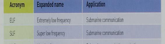
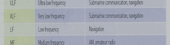
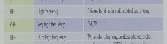
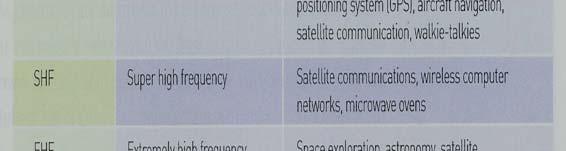
8 The Radio Spectrum The frequency range of the electromagnetic spectrum between 3 Hz and 300 GHz is called the radio spectrum The radio spectrum is further divided into regions called frequency bands Radio Frequency (RF) systems use bands with in the radio spectrum for communication
9
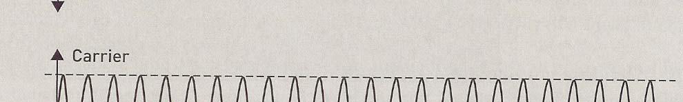
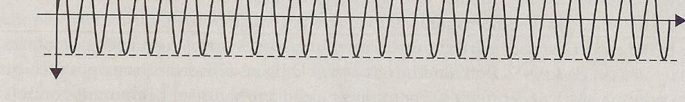
10 Modulation/Demodulation Modulation is a technique used to convert a low frequency signal (information signal) to a higher h frequency signal (modulated signal) using a higher frequency signal (carrier). In modulation, the carrier is modulated (reshaped) according to the information signal Demodulation is the opposite technique where information signal is extracted from the carrier Analogue Modulation is used to transmit analogue signals and digital modulation is used to convert digital signals
11 a. Analogue Modulation The main idea of analogue modulation is to carry the information signal onto the carrier s amplitude, frequency or phase. Carrying the information signal onto the carrier s amplitude Carrying the information signal onto the carrier s frequency Carrying the information signal onto the carrier s phase
")


12 1. Amplitude Modulation (AM) envelop The carrier s amplitude is varied in proportion to the amplitude of the information signal
13 Amplitude Modulation In AM,the information is carried on the carrier s amplitude The demodulation is achieved by detecting thevariation of themodulated signal ss amplitude called envelop AM is prone to noise interference as noise may change the amplitude of the modulated signal


14 2. Frequency Modulation (FM) The carrier s frequency is varied in proportion to the amplitude of the information signal
15 Frequency Modulation In FM,the information is carried on the carrier s frequency The demodulation is achieved by detecting thevariation of themodulated signal ss frequency FM better performs in the presence of noise because noise don t change thefrequency of the modulated signal
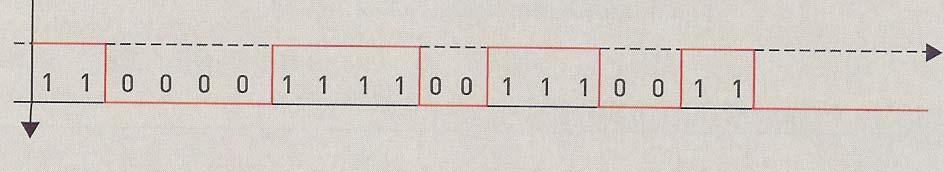
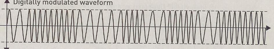
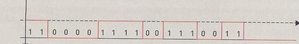
16 b. Digital Modulation Digital information is made of 2 levels of amplitude representing two logical levels (0 and 1) In digital modulation the 0 and 1 are carried on the carrier s amplitude, frequency and phase Carrying the 0s and 1s onto the carrier s amplitude Carrying the 0s and 1s onto the carrier s frequency Carrying the 0s and 1s onto the carrier s phase
17 1. Amplitude Shift Keying (ASK) The amplitude of the carrier varies according to the binary amplitude of the information signal In ASK, the modulated signal has 2 amplitude Logic 0 is modulated with amplitude of 0 and logic 1 is modulated with maximum amplitude value
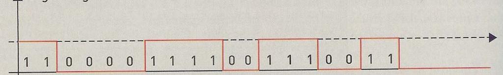
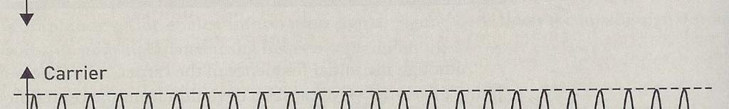
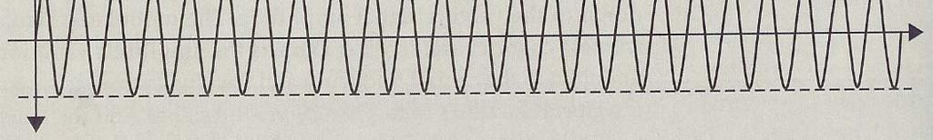
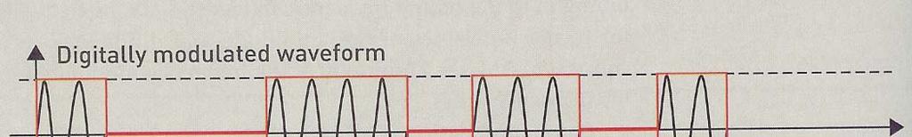
18 ASK
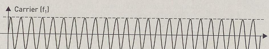
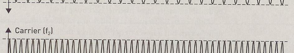
19 2. Frequency Shift Keying (FSK) The frequency of the carrier varies according to the binary amplitude of the information signal In FSK, the modulated signal has 2 frequencies Logic 0 is modulated using one frequency and logic 1 is modulated using another frequency
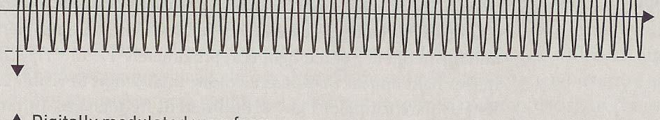
20 FSK
21 3. Phase Shift Keying (PSK) The phase of the carrier varies according to the binary amplitude of the information signal In PSK, the modulated signal has 2 different phases Logic 0 is modulated using the carrier s phase and logic 1 is modulated using the same carrier with a phase shift.
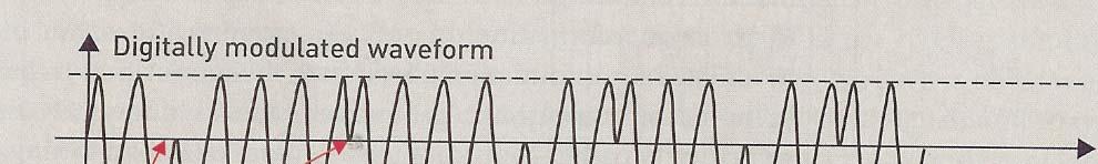
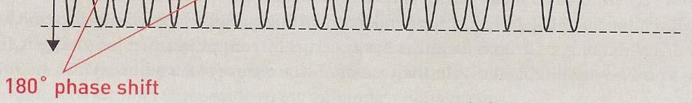
22 PSK
23 ASK/FSK/PSK The bandwidth of the FSK is twice as much the bandwidth of the PSK and ASK FSK and PSK have better quality than ASK PSK is used for mobile digital i mobile telephony FSK is used in fax machines ASK is used in satellite tllit communications
24 Attenuation When the signal travels through a medium such as air or cable, it loses energy The loss of energy is called attenuation As the distance between the transmitter and receiver increases, signal attenuation increases Thesignal reduction in air follow theinverse square law
25 Attenuation in the air Attenuation in air is governed by the inverse square law Inverse Square law states that received signal power (P r) is inversely proportional the transmit signal power (P t ), the relation between the received and transmit signal powers is given by this equation: P r = P t /r 2 (3) where r is the distance between the transmitter and the receiver
26 Electric Signal Power The power of an electrical signal is the square value of its voltage; P = V 2 (W) (4) In communication i we like to express the power in decibels; This relation used to express signal power in decibels: P[dB] = 10 log 10 P (db) (5)
27 Inverse Square law in db P = 2 r Pt/r (W) P r [db] = 10 log 10 P t 10log 10 (r 2 ) P r [db] = P t [db] 20 log 10 r (6)
28 Example 1 Calculate the received power in db when the distance between a 100 W transmitter and a receiver is mm? Solution Pr[dB] = Pt[dB] 20 log r Pr[dB] = 10 log log 10 P[dB] Pr[dB] = = 0 db
29 Attenuation in wired medium In wired medium, signal attenuation depends on the type of the medium as some type of wired mediums are more prone to attenuation than other types of wired medium For example, some fiber optics cable transmit signal attenuates at the rate of (0.2 db/km) compare to coaxial cable which attenuates at (175 db/km) in the best case
30 Example 2 (using repeaters) (a) Calculate the received power at the end of a 30 km cable that has attenuation rate of (10 db/km) if the transmit power is 100 db? (b) Using 2 Repeaters spaced at 10 km each, what is the received power if the repeater can amplify the received signal by 10 db? Tx Pt = 100 db 10 db/ km 30 km Rx Pr =?
31 Solution (a): P r = * 10 = 200 db (b) Tx Pt = 100 db 10 db/ km R 1 R2 10 km 10 km 10 km Rx Pr =? At R1 P r, 1 = X 10 = 0 db P t,1 = = 10 db At R2 P r,2 = x10 = 90 db P t, 2 = = 80 db P r = 80 10X10 = 180 db
32 Noise Noise is undesirable electric energy that falls within the bandwidth of the transmitted signal. As signal bandwidth increases, noise interference increases Noise interference will result in poor quality of the received signal. Noise interference with the transmitted signal is unavoidable.
33 Communication system Noise Transmitter Medium Receiver
34 Noise Categories A. External Noise: Noise that is generated in the communication medium: 1. Atmospheric Noise 2. Extraterrestrial Noise 3. Man made noise B. Internal Noise: Noise that is generated inside the Receiver hardware: 1. Thermal Noise; temperature dependant noise
35 Signal To Noise Ratio (SNR) SNR is a figure of merit that expresses the ratio of the received signal power (P r ) to the noise power (P N ) SNR = P r / P N SNR [db] = P r [db] P N [db] (7) Using equation (6), (7) can be re written as: SNR [db] = P t [db] 20 log 10 r P N [db]. (8)
36 Example3 Calculate the SNR at the receiver when the distance between a 100 W transmitter and the receiver is 1 km and the noise power in the channel is 15 db? How could we increase SNR of the received signal? Solution SNR [db] = 10 log log = = 55 db
37 Error Correction in Digital Communication Incorrect detection of a binary digit will result in error. Signal attenuation and noise interference are the factors that cause errors. The rate of error depends on the type of modulation and the SNR of the received signal In digital communication, errors are detected and corrected using special coding techniques These coding techniques are based on the addition of extra bits, calledredundant bits. The redundant bits are not part of the original information but added specifically for error checking
38 Error Control Coding Error control coding (ECC) is the name of techniques used to encode the message prior to transmission. Block coding are a type of ECC, Block coding consist 2 type of coding: 1. Single Parity Checking 2. Rectangular Coding
39 1. Single Parity Checking Single Parity Checking is implemented simply by adding a single redundant bit called the parity bit This parity bit is calculated by XORing all bits in the block If the block consists even number of 1 s the output tof XORing the block bits is 0 and if the block consists odd number of 1 s the output of XORing the block bits is 1
40 Example 4 Encode the following blocks using single check parity: a b Solution a. 1 XOR 1 XOR 0 XOR 0 XOR 1 XOR 1 XOR 0 = b. 1 XOR 0 XOR 0 XOR 0 XOR 0 XOR 1 XOR 1 =
41 Example 5 The following blocks has been received, Determine whether they have been received correctly or not knowing that those codes have been encoded using single parity checking? a received incorrectly b received incorrectly c received correctly
42 Limitations on Single parity Checking 1. The receiver can detect that an error has occurred but it cannot determine exactly which bit is in error. However parity checking is still useful in a way that, once error is detected the Receiver will inform the transmitter to re transmit the block again 2. It only work for odd number of errors occurring during transmission
43 Rectangular Coding Rectangular Coding is more complex than single parity checking. These coding technique can detect and correct errors. In this technique, 2 blocks of data (encoded using single parity checking) are XORed together and the resulted block redundant block is added at the end of the message
44 Example 6 Encode the following blocks of data using rectangular coding: Solution XOR the code to transmitted is
45 Error Detection and Correction To detect an error, each block is checked using single parity checking If error is detected in one of the two first blocks, then the error can be corrected To correct the error, XOR the correct block with the redundant block and compare the result with the incorrect block. Error is detected when the output of XORing dose not match its corresponding in the incorrect bit
46 Example 7 Detect and Correct errors in the following stream of bits knowing that the received stream has been encoded using rectangular coding Received data stream: Solution received ed correctly received incorrectly To correct the second block XOR the first block with the redundant block XOR therefore the error was in the fifth bit in the second block
47 Digital Communication System Microphone ADC Encoder (Error) Modulator Antenna Transmitter Noise Medium + Antenna Demodulator Decoder (Error) DAC Speaker Receiver
INTRODUCTION TO COMMUNICATION SYSTEMS AND TRANSMISSION MEDIA
 COMM.ENG INTRODUCTION TO COMMUNICATION SYSTEMS AND TRANSMISSION MEDIA 9/9/2017 LECTURES 1 Objectives To give a background on Communication system components and channels (media) A distinction between analogue
Chapter-15. Communication systems -1 mark Questions
 Chapter-15 Communication systems -1 mark Questions 1) What are the three main units of a Communication System? 2) What is meant by Bandwidth of transmission? 3) What is a transducer? Give an example. 4)
Outline / Wireless Networks and Applications Lecture 3: Physical Layer Signals, Modulation, Multiplexing. Cartoon View 1 A Wave of Energy
 Outline 18-452/18-750 Wireless Networks and Applications Lecture 3: Physical Layer Signals, Modulation, Multiplexing Peter Steenkiste Carnegie Mellon University Spring Semester 2017 http://www.cs.cmu.edu/~prs/wirelesss17/
What is a Communications System?
 Introduction to Communication Systems: An Overview James Flynn Sharlene Katz What is a Communications System? A communications system transfers an information bearing signal from a source to one or more
Computer Networks - Xarxes de Computadors
 Computer Networks - Xarxes de Computadors Outline Course Syllabus Unit 1: Introduction Unit 2. IP Networks Unit 3. Point to Point Protocols -TCP Unit 4. Local Area Networks, LANs 1 Outline Introduction
HY448 Sample Problems
 HY448 Sample Problems 10 November 2014 These sample problems include the material in the lectures and the guided lab exercises. 1 Part 1 1.1 Combining logarithmic quantities A carrier signal with power
Lecture 2: Links and Signaling. CSE 123: Computer Networks Stefan Savage
 Lecture 2: Links and Signaling CSE 123: Computer Networks Stefan Savage Lecture 2 Overview Signaling Channel characteristics Types of physical media Modulation Narrowband vs. Broadband Encoding schemes
UNIT-1. Basic signal processing operations in digital communication
 UNIT-1 Lecture-1 Basic signal processing operations in digital communication The three basic elements of every communication systems are Transmitter, Receiver and Channel. The Overall purpose of this system
Announcements : Wireless Networks Lecture 3: Physical Layer. Bird s Eye View. Outline. Page 1
 Announcements 18-759: Wireless Networks Lecture 3: Physical Layer Please start to form project teams» Updated project handout is available on the web site Also start to form teams for surveys» Send mail
Chapter 1 Introduction
 Wireless Information Transmission System Lab. Chapter 1 Introduction National Sun Yat-sen University Table of Contents Elements of a Digital Communication System Communication Channels and Their Wire-line
Chapter-1: Introduction
 Chapter-1: Introduction The purpose of a Communication System is to transport an information bearing signal from a source to a user destination via a communication channel. MODEL OF A COMMUNICATION SYSTEM
COMMUNICATION SYSTEMS -I
 COMMUNICATION SYSTEMS -I Communication : It is the act of transmission of information. ELEMENTS OF A COMMUNICATION SYSTEM TRANSMITTER MEDIUM/CHANNEL: The physical medium that connects transmitter to receiver
Announcement : Wireless Networks Lecture 3: Physical Layer. A Reminder about Prerequisites. Outline. Page 1
 Announcement 18-759: Wireless Networks Lecture 3: Physical Layer Peter Steenkiste Departments of Computer Science and Electrical and Computer Engineering Spring Semester 2010 http://www.cs.cmu.edu/~prs/wirelesss10/
ENGR 4323/5323 Digital and Analog Communication
 ENGR 4323/5323 Digital and Analog Communication Chapter 1 Introduction Engineering and Physics University of Central Oklahoma Dr. Mohamed Bingabr Course Materials Textbook: Modern Digital and Analog Communication,
Introduction to Telecommunications and Computer Engineering Unit 3: Communications Systems & Signals
 Introduction to Telecommunications and Computer Engineering Unit 3: Communications Systems & Signals Syedur Rahman Lecturer, CSE Department North South University syedur.rahman@wolfson.oxon.org Acknowledgements
Lecture 2: Links and Signaling"
 Lecture 2: Links and Signaling" CSE 123: Computer Networks Alex C. Snoeren HW 1 out tomorrow, due next 10/9! Lecture 2 Overview" Signaling Types of physical media Shannon s Law and Nyquist Limit Encoding
Digital Communication System
 Digital Communication System Purpose: communicate information at certain rate between geographically separated locations reliably (quality) Important point: rate, quality spectral bandwidth requirement
Digital Communication System
 Digital Communication System Purpose: communicate information at required rate between geographically separated locations reliably (quality) Important point: rate, quality spectral bandwidth, power requirements
CSE 123: Computer Networks Alex C. Snoeren. Project 1 out Today, due 10/26!
 CSE 123: Computer Networks Alex C. Snoeren Project 1 out Today, due 10/26! Signaling Types of physical media Shannon s Law and Nyquist Limit Encoding schemes Clock recovery Manchester, NRZ, NRZI, etc.
SAMPLE. UEENEEH046B Solve fundamental problems in electronic communications systems. Learner Workbook. UEE07 Electrotechnology Training Package
 UEE07 Electrotechnology Training Package UEENEEH046B Solve fundamental problems in electronic communications systems Learner Workbook Version 1 Training and Education Support Industry Skills Unit Meadowbank
CS441 Mobile & Wireless Computing Communication Basics
 Department of Computer Science Southern Illinois University Carbondale CS441 Mobile & Wireless Computing Communication Basics Dr. Kemal Akkaya E-mail: kemal@cs.siu.edu Kemal Akkaya Mobile & Wireless Computing
Basic Concepts in Data Transmission
 Basic Concepts in Data Transmission EE450: Introduction to Computer Networks Professor A. Zahid A.Zahid-EE450 1 Data and Signals Data is an entity that convey information Analog Continuous values within
Contents. Telecom Service Chae Y. Lee. Data Signal Transmission Transmission Impairments Channel Capacity
 Data Transmission Contents Data Signal Transmission Transmission Impairments Channel Capacity 2 Data/Signal/Transmission Data: entities that convey meaning or information Signal: electric or electromagnetic
Principles of Communications ECS 332
 Principles of Communications ECS 332 Asst. Prof. Dr. Prapun Suksompong prapun@siit.tu.ac.th 5. Angle Modulation Office Hours: BKD, 6th floor of Sirindhralai building Wednesday 4:3-5:3 Friday 4:3-5:3 Example
Physical-Layer Services and Systems
 Physical-Layer Services and Systems Figure Transmission medium and physical layer Figure Classes of transmission media GUIDED MEDIA Guided media, which are those that provide a conduit from one device
Chapter 7 Multiple Division Techniques for Traffic Channels
 Introduction to Wireless & Mobile Systems Chapter 7 Multiple Division Techniques for Traffic Channels Outline Introduction Concepts and Models for Multiple Divisions Frequency Division Multiple Access
CS263: Wireless Communications and Sensor Networks
 CS263: Wireless Communications and Sensor Networks Matt Welsh Lecture 3: Antennas, Propagation, and Spread Spectrum September 30, 2004 2004 Matt Welsh Harvard University 1 Today's Lecture Antennas and
Data Communication. Chapter 3 Data Transmission
 Data Communication Chapter 3 Data Transmission ١ Terminology (1) Transmitter Receiver Medium Guided medium e.g. twisted pair, coaxial cable, optical fiber Unguided medium e.g. air, water, vacuum ٢ Terminology
 UNIT 2 DIGITAL COMMUNICATION DIGITAL COMMUNICATION-Introduction The techniques used to modulate digital information so that it can be transmitted via microwave, satellite or down a cable pair is different
Lecture #2. EE 471C / EE 381K-17 Wireless Communication Lab. Professor Robert W. Heath Jr.
 Lecture #2 EE 471C / EE 381K-17 Wireless Communication Lab Professor Robert W. Heath Jr. Preview of today s lecture u Introduction to digital communication u Components of a digital communication system
Chapter 2. Physical Layer
 Chapter 2 Physical Layer Lecture 1 Outline 2.1 Analog and Digital 2.2 Transmission Media 2.3 Digital Modulation and Multiplexing 2.4 Transmission Impairment 2.5 Data-rate Limits 2.6 Performance Physical
COMM 704: Communication Systems
 COMM 704: Communication Lecture 1: Introduction Dr. Mohamed Abd El Ghany, Mohamed.abdel-ghany@guc.edu.eg Course Objective Give an introduction to the basic concepts of electronic communication systems
Vehicle Networks. Wireless communication basics. Univ.-Prof. Dr. Thomas Strang, Dipl.-Inform. Matthias Röckl
 Vehicle Networks Wireless communication basics Univ.-Prof. Dr. Thomas Strang, Dipl.-Inform. Matthias Röckl Outline Wireless Signal Propagation Electro-magnetic waves Signal impairments Attenuation Distortion
COSC 3213: Computer Networks I: Chapter 3 Handout #4. Instructor: Dr. Marvin Mandelbaum Department of Computer Science York University Section A
 COSC 3213: Computer Networks I: Chapter 3 Handout #4 Instructor: Dr. Marvin Mandelbaum Department of Computer Science York University Section A Topics: 1. Line Coding: Unipolar, Polar,and Inverted ; Bipolar;
Course Code: EE-411 Teacher: Engr.Ahmad Bilal Multiple choice & Short Questions notes
 Department of Electrical (POWER) Engineering Swedish College of Engineering & Technology Rahim yar khan Subject: Communication systems Course Code: EE-411 Teacher: Engr.Ahmad Bilal Multiple choice & Short
Data Encoding g(p (part 2)
") Data Encoding g(p (part 2) CSE 3213 Instructor: U.T. Nguyen 10/11/2007 12:44 PM 1 Analog Data, Digital Signals (5.3) 2 1 Analog Data, Digital Signals Digitization Conversion of analog data into digital
Data Encoding g(p (part 2) CSE 3213 Instructor: U.T. Nguyen 10/11/2007 12:44 PM 1 Analog Data, Digital Signals (5.3) 2 1 Analog Data, Digital Signals Digitization Conversion of analog data into digital
EITF25 Internet Techniques and Applications L2: Physical layer. Stefan Höst
 EITF25 Internet Techniques and Applications L2: Physical layer Stefan Höst Data vs signal Data: Static representation of information For storage Signal: Dynamic representation of information For transmission
WIRELESS COMMUNICATIONS PRELIMINARIES
 WIRELESS COMMUNICATIONS Preliminaries Radio Environment Modulation Performance PRELIMINARIES db s and dbm s Frequency/Time Relationship Bandwidth, Symbol Rate, and Bit Rate 1 DECIBELS Relative signal strengths
Chapter 1: Introduction. EET-223: RF Communication Circuits Walter Lara
 Chapter 1: Introduction EET-223: RF Communication Circuits Walter Lara Introduction Electronic communication involves transmission over medium from source to destination Information can contain voice,
Overview. Lecture 3. Terminology. Terminology. Background. Background. Transmission basics. Transmission basics. Two signal types
 Lecture 3 Transmission basics Chapter 3, pages 75-96 Dave Novak School of Business University of Vermont Overview Transmission basics Terminology Signal Channel Electromagnetic spectrum Two signal types
CHAPTER 2. Instructor: Mr. Abhijit Parmar Course: Mobile Computing and Wireless Communication ( )
") CHAPTER 2 Instructor: Mr. Abhijit Parmar Course: Mobile Computing and Wireless Communication (2170710) Syllabus Chapter-2.3 Modulation Techniques Reasons for Choosing Encoding Techniques Digital data,
CHAPTER 2 Instructor: Mr. Abhijit Parmar Course: Mobile Computing and Wireless Communication (2170710) Syllabus Chapter-2.3 Modulation Techniques Reasons for Choosing Encoding Techniques Digital data,
CS307 Data Communication
 CS307 Data Communication Course Objectives Build an understanding of the fundamental concepts of data transmission. Familiarize the student with the basics of encoding of analog and digital data Preparing
Communication and signals. Book page Syllabus
 Communication and signals Book page 103 105 Syllabus 3.23 3.25 What do these have to do with one another? Homer and the Internet What are the codes they use? Do you know what changed WWII? The Imitation
Some key functions implemented in the transmitter are modulation, filtering, encoding, and signal transmitting (to be elaborated)
") 1 An electrical communication system enclosed in the dashed box employs electrical signals to deliver user information voice, audio, video, data from source to destination(s). An input transducer may be
1 An electrical communication system enclosed in the dashed box employs electrical signals to deliver user information voice, audio, video, data from source to destination(s). An input transducer may be
ECE 457 Communication Systems. Selin Aviyente Assistant Professor Electrical & Computer Engineering
 ECE 457 Communication Systems Selin Aviyente Assistant Professor Electrical & Computer Engineering Announcements Class Web Page: http://www.egr.msu.edu/~aviyente/ece 457.htm M, W, F 10:20-11:10 a.m. Office
Data and Computer Communications. Chapter 3 Data Transmission
 Data and Computer Communications Chapter 3 Data Transmission Data Transmission quality of the signal being transmitted The successful transmission of data depends on two factors: characteristics of the
Wireless Communication Fading Modulation
 EC744 Wireless Communication Fall 2008 Mohamed Essam Khedr Department of Electronics and Communications Wireless Communication Fading Modulation Syllabus Tentatively Week 1 Week 2 Week 3 Week 4 Week 5
Lecture Fundamentals of Data and signals
 IT-5301-3 Data Communications and Computer Networks Lecture 05-07 Fundamentals of Data and signals Lecture 05 - Roadmap Analog and Digital Data Analog Signals, Digital Signals Periodic and Aperiodic Signals
PRINCIPLES OF COMMUNICATION SYSTEMS. Lecture 1- Introduction Elements, Modulation, Demodulation, Frequency Spectrum
 PRINCIPLES OF COMMUNICATION SYSTEMS Lecture 1- Introduction Elements, Modulation, Demodulation, Frequency Spectrum Topic covered Introduction to subject Elements of Communication system Modulation General
Bandwidth Radar Receivers
 Analog Optical Links for Wide Bandwidth Radar Receivers Sean Morris & Brian Potts MQP Presentation Group 33 14 October 29 This work was sponsored by the Space and Missile Systems Center, under Air Force
DATA TRANSMISSION. ermtiong. ermtiong
 DATA TRANSMISSION Analog Transmission Analog signal transmitted without regard to content May be analog or digital data Attenuated over distance Use amplifiers to boost signal Also amplifies noise DATA
UNIT- 7. Frequencies above 30Mhz tend to travel in straight lines they are limited in their propagation by the curvature of the earth.
 UNIT- 7 Radio wave propagation and propagation models EM waves below 2Mhz tend to travel as ground waves, These wave tend to follow the curvature of the earth and lose strength rapidly as they travel away
Elements of Communication System Channel Fig: 1: Block Diagram of Communication System Terminology in Communication System
 Content:- Fundamentals of Communication Engineering : Elements of a Communication System, Need of modulation, electromagnetic spectrum and typical applications, Unit V (Communication terminologies in communication
Adapted from Dr. Joe Montana (George mason University) Dr. James
 Dr. James") ink Budget Adapted from Dr. Joe Montana (George mason University) Dr. James W. apean course notes Dr. Jeremy Allnutt course notes And some internet resources + Tim Pratt book 1 ink Power Budget Tx EIRP
ink Budget Adapted from Dr. Joe Montana (George mason University) Dr. James W. apean course notes Dr. Jeremy Allnutt course notes And some internet resources + Tim Pratt book 1 ink Power Budget Tx EIRP
Advanced Digital Communication
 Advanced Digital Communication Manjunatha. P manjup.jnnce@gmail.com Professor Dept. of ECE J.N.N. College of Engineering, Shimoga March 14, 2013 ADC Syllabus SEMSTER - II ADVANCED DIGITAL COMMUNICATIONS
EC 554 Data Communications
 EC 554 Data Communications Mohamed Khedr http://webmail. webmail.aast.edu/~khedraast.edu/~khedr Syllabus Tentatively Week 1 Week 2 Week 3 Week 4 Week 5 Week 6 Week 7 Week 8 Week 9 Week 10 Week 11 Week
SEN366 Computer Networks
 SEN366 Computer Networks Prof. Dr. Hasan Hüseyin BALIK (5 th Week) 5. Signal Encoding Techniques 5.Outline An overview of the basic methods of encoding digital data into a digital signal An overview of
Contents. ITS323: Introduction to Data Communications CSS331: Fundamentals of Data Communications. Transmission Media and Spectrum.
 2 ITS323: Introduction to Data Communications CSS331: Fundamentals of Data Communications Sirindhorn International Institute of Technology Thammasat University Prepared by Steven Gordon on 3 August 2015
ITS323: Introduction to Data Communications CSS331: Fundamentals of Data Communications
 ITS323: Introduction to Data Communications CSS331: Fundamentals of Data Communications Sirindhorn International Institute of Technology Thammasat University Prepared by Steven Gordon on 3 August 2015
E-716-A Mobile Communications Systems. Lecture #2 Basic Concepts of Wireless Transmission (p1) Instructor: Dr. Ahmad El-Banna
 Instructor: Dr. Ahmad El-Banna") October 2014 Ahmad El-Banna Integrated Technical Education Cluster At AlAmeeria E-716-A Mobile Communications Systems Lecture #2 Basic Concepts of Wireless Transmission (p1) Instructor: Dr. Ahmad El-Banna
October 2014 Ahmad El-Banna Integrated Technical Education Cluster At AlAmeeria E-716-A Mobile Communications Systems Lecture #2 Basic Concepts of Wireless Transmission (p1) Instructor: Dr. Ahmad El-Banna
Lecture 3 Concepts for the Data Communications and Computer Interconnection
 Lecture 3 Concepts for the Data Communications and Computer Interconnection Aim: overview of existing methods and techniques Terms used: -Data entities conveying meaning (of information) -Signals data
Chapter 7. Multiple Division Techniques
 Chapter 7 Multiple Division Techniques 1 Outline Frequency Division Multiple Access (FDMA) Division Multiple Access (TDMA) Code Division Multiple Access (CDMA) Comparison of FDMA, TDMA, and CDMA Walsh
CSE 461 Bits and Links. David Wetherall
 CSE 461 Bits and Links David Wetherall djw@cs.washington.edu Topic How do we send a message across a wire or wireless link? The physical/link layers: 1. Different kinds of media 2. Fundamental limits 3.
RF Basics 15/11/2013
 27 RF Basics 15/11/2013 Basic Terminology 1/2 dbm is a measure of RF Power referred to 1 mw (0 dbm) 10mW(10dBm), 500 mw (27dBm) PER Packet Error Rate [%] percentage of the packets not successfully received
Terminology (1) Chapter 3. Terminology (3) Terminology (2) Transmitter Receiver Medium. Data Transmission. Direct link. Point-to-point.
 Chapter 3. Terminology (3) Terminology (2) Transmitter Receiver Medium. Data Transmission. Direct link. Point-to-point.") Terminology (1) Chapter 3 Data Transmission Transmitter Receiver Medium Guided medium e.g. twisted pair, optical fiber Unguided medium e.g. air, water, vacuum Spring 2012 03-1 Spring 2012 03-2 Terminology
Terminology (1) Chapter 3 Data Transmission Transmitter Receiver Medium Guided medium e.g. twisted pair, optical fiber Unguided medium e.g. air, water, vacuum Spring 2012 03-1 Spring 2012 03-2 Terminology
Mobile & Wireless Networking. Lecture 2: Wireless Transmission (2/2)
") 192620010 Mobile & Wireless Networking Lecture 2: Wireless Transmission (2/2) [Schiller, Section 2.6 & 2.7] [Reader Part 1: OFDM: An architecture for the fourth generation] Geert Heijenk Outline of Lecture
192620010 Mobile & Wireless Networking Lecture 2: Wireless Transmission (2/2) [Schiller, Section 2.6 & 2.7] [Reader Part 1: OFDM: An architecture for the fourth generation] Geert Heijenk Outline of Lecture
Department of Electronics & Telecommunication Engg. LAB MANUAL. B.Tech V Semester [ ] (Branch: ETE)
![Department of Electronics & Telecommunication Engg. LAB MANUAL. B.Tech V Semester [ ] (Branch: ETE)](/thumbs/86/93078052.jpg "Department of Electronics & Telecommunication Engg. LAB MANUAL. B.Tech V Semester [ ] (Branch: ETE)") Department of Electronics & Telecommunication Engg. LAB MANUAL SUBJECT:-DIGITAL COMMUNICATION SYSTEM [BTEC-501] B.Tech V Semester [2013-14] (Branch: ETE) KCT COLLEGE OF ENGG & TECH., FATEHGARH PUNJAB TECHNICAL
Department of Electronics & Telecommunication Engg. LAB MANUAL SUBJECT:-DIGITAL COMMUNICATION SYSTEM [BTEC-501] B.Tech V Semester [2013-14] (Branch: ETE) KCT COLLEGE OF ENGG & TECH., FATEHGARH PUNJAB TECHNICAL
In this lecture. System Model Power Penalty Analog transmission Digital transmission
 System Model Power Penalty Analog transmission Digital transmission In this lecture Analog Data Transmission vs. Digital Data Transmission Analog to Digital (A/D) Conversion Digital to Analog (D/A) Conversion
Week 2 Lecture 1. Introduction to Communication Networks. Review: Analog and digital communications
 Week 2 Lecture 1 Introduction to Communication Networks Review: Analog and digital communications Topic: Internet Trend, Protocol, Transmission Principle Digital Communications is the foundation of Internet
THE BASICS OF RADIO SYSTEM DESIGN
 THE BASICS OF RADIO SYSTEM DESIGN Mark Hunter * Abstract This paper is intended to give an overview of the design of radio transceivers to the engineer new to the field. It is shown how the requirements
two computers. 2- Providing a channel between them for transmitting and receiving the signals through it.
 1. Introduction: Communication is the process of transmitting the messages that carrying information, where the two computers can be communicated with each other if the two conditions are available: 1-
Data and Computer Communications Chapter 3 Data Transmission
 Data and Computer Communications Chapter 3 Data Transmission Eighth Edition by William Stallings Transmission Terminology data transmission occurs between a transmitter & receiver via some medium guided
Spread Spectrum Communications and Jamming Prof. Kutty Shajahan M G S Sanyal School of Telecommunications Indian Institute of Technology, Kharagpur
 Spread Spectrum Communications and Jamming Prof. Kutty Shajahan M G S Sanyal School of Telecommunications Indian Institute of Technology, Kharagpur Lecture - 06 Tutorial I Hello friends, welcome to this
CHAPTER -15. Communication Systems
 CHAPTER -15 Communication Systems COMMUNICATION Communication is the act of transmission and reception of information. COMMUNICATION SYSTEM: A system comprises of transmitter, communication channel and
Chapter 4. Communication System Design and Parameters
 Chapter 4 Communication System Design and Parameters CHAPTER 4 COMMUNICATION SYSTEM DESIGN AND PARAMETERS 4.1. Introduction In this chapter the design parameters and analysis factors are described which
Data and Computer Communications Chapter 4 Transmission Media
 Data and Computer Communications Chapter 4 Transmission Media Ninth Edition by William Stallings Data and Computer Communications, Ninth Edition by William Stallings, (c) Pearson Education - Prentice Hall,
Antennas and Propagation
 Antennas and Propagation Chapter 5 Introduction An antenna is an electrical conductor or system of conductors Transmission - radiates electromagnetic energy into space Reception - collects electromagnetic
Chapter 1: Telecommunication Fundamentals
 Chapter 1: Telecommunication Fundamentals Block Diagram of a communication system Noise n(t) m(t) Information (base-band signal) Signal Processing Carrier Circuits s(t) Transmission Medium r(t) Signal
Overview. Chapter 4. Design Factors. Electromagnetic Spectrum
 Chapter 4 Transmission Media Overview Guided - wire Unguided - wireless Characteristics and quality determined by medium and signal For guided, the medium is more important For unguided, the bandwidth
CSEP 561 Bits and Links. David Wetherall
 CSEP 561 Bits and Links David Wetherall djw@cs.washington.edu Topic How do we send a message across a wire or wireless link? The physical/link layers: 1. Different kinds of media 2. Fundamental limits
OptiSystem applications: Digital modulation analysis (PSK)
") OptiSystem applications: Digital modulation analysis (PSK) 7 Capella Court Nepean, ON, Canada K2E 7X1 +1 (613) 224-4700 www.optiwave.com 2009 Optiwave Systems, Inc. Introduction PSK modulation Digital
OptiSystem applications: Digital modulation analysis (PSK) 7 Capella Court Nepean, ON, Canada K2E 7X1 +1 (613) 224-4700 www.optiwave.com 2009 Optiwave Systems, Inc. Introduction PSK modulation Digital
Problem Sheet 1 Probability, random processes, and noise
 Problem Sheet 1 Probability, random processes, and noise 1. If F X (x) is the distribution function of a random variable X and x 1 x 2, show that F X (x 1 ) F X (x 2 ). 2. Use the definition of the cumulative
Last Time. Transferring Information. Today (& Tomorrow (& Tmrw)) Application Layer Example Protocols ftp http Performance.
) Application Layer Example Protocols ftp http Performance.") 15-441 Lecture 5 Last Time Physical Layer & Link Layer Basics Copyright Seth Goldstein, 2008 Application Layer Example Protocols ftp http Performance Application Presentation Session Transport Network
15-441 Lecture 5 Last Time Physical Layer & Link Layer Basics Copyright Seth Goldstein, 2008 Application Layer Example Protocols ftp http Performance Application Presentation Session Transport Network
CT-516 Advanced Digital Communications
 CT-516 Advanced Digital Communications Yash Vasavada Winter 2017 DA-IICT Lecture 17 Channel Coding and Power/Bandwidth Tradeoff 20 th April 2017 Power and Bandwidth Tradeoff (for achieving a particular
Introduction to Communications Part Two: Physical Layer Ch3: Data & Signals
 Introduction to Communications Part Two: Physical Layer Ch3: Data & Signals Kuang Chiu Huang TCM NCKU Spring/2008 Goals of This Class Through the lecture of fundamental information for data and signals,
College of information Technology Department of Information Networks Telecommunication & Networking I Chapter DATA AND SIGNALS 1 من 42
 3.1 DATA AND SIGNALS 1 من 42 Communication at application, transport, network, or data- link is logical; communication at the physical layer is physical. we have shown only ; host- to- router, router-to-
Antenna & Propagation. Basic Radio Wave Propagation
 For updated version, please click on http://ocw.ump.edu.my Antenna & Propagation Basic Radio Wave Propagation by Nor Hadzfizah Binti Mohd Radi Faculty of Electric & Electronics Engineering hadzfizah@ump.edu.my
Lecture 3: Data Transmission
 Lecture 3: Data Transmission 1 st semester 1439-2017 1 By: Elham Sunbu OUTLINE Data Transmission DATA RATE LIMITS Transmission Impairments Examples DATA TRANSMISSION The successful transmission of data
Noise and Interference Limited Systems
 Chapter 3 Noise and Interference Limited Systems 47 Basics of link budgets Link budgets show how different components and propagation processes influence the available SNR Link budgets can be used to compute
Wireless Communication Systems: Implementation perspective
 Wireless Communication Systems: Implementation perspective Course aims To provide an introduction to wireless communications models with an emphasis on real-life systems To investigate a major wireless
Chapter 4 Radio Communication Basics
 Chapter 4 Radio Communication Basics Chapter 4 Radio Communication Basics RF Signal Propagation and Reception Basics and Keywords Transmitter Power and Receiver Sensitivity Power - antenna gain: G TX,
CS-435 spring semester Network Technology & Programming Laboratory. Stefanos Papadakis & Manolis Spanakis
 CS-435 spring semester 2016 Network Technology & Programming Laboratory University of Crete Computer Science Department Stefanos Papadakis & Manolis Spanakis CS-435 Lecture preview Wireless Networking
Chapter 3. Data Transmission
 Chapter 3 Data Transmission Reading Materials Data and Computer Communications, William Stallings Terminology (1) Transmitter Receiver Medium Guided medium (e.g. twisted pair, optical fiber) Unguided medium
Optical Delay Line Application Note
 1 Optical Delay Line Application Note 1.1 General Optical delay lines system (ODL), incorporates a high performance lasers such as DFBs, optical modulators for high operation frequencies, photodiodes,
IST 220 Exam 1 Notes Prepared by Dan Veltri
 Chapter 1 & 2 IST 220 Exam 1 Notes Prepared by Dan Veltri Exam 1 is scheduled for Wednesday, October 6 th, in class. Exam review will be held Monday, October 4 th, in class. The internet is expanding rapidly
Computer Networks. Week 03 Founda(on Communica(on Concepts. College of Information Science and Engineering Ritsumeikan University
 Computer Networks Week 03 Founda(on Communica(on Concepts College of Information Science and Engineering Ritsumeikan University Agenda l Basic topics of electromagnetic signals: frequency, amplitude, degradation
Chapter 3 Data and Signals
 Chapter 3 Data and Signals 3.2 To be transmitted, data must be transformed to electromagnetic signals. 3-1 ANALOG AND DIGITAL Data can be analog or digital. The term analog data refers to information that
Satellite Signals and Communications Principles. Dr. Ugur GUVEN Aerospace Engineer (P.hD)
") Satellite Signals and Communications Principles Dr. Ugur GUVEN Aerospace Engineer (P.hD) Principle of Satellite Signals In essence, satellite signals are electromagnetic waves that travel from the satellite
Satellite Signals and Communications Principles Dr. Ugur GUVEN Aerospace Engineer (P.hD) Principle of Satellite Signals In essence, satellite signals are electromagnetic waves that travel from the satellite
Chapter 3 Data Transmission COSC 3213 Summer 2003
 Chapter 3 Data Transmission COSC 3213 Summer 2003 Courtesy of Prof. Amir Asif Definitions 1. Recall that the lowest layer in OSI is the physical layer. The physical layer deals with the transfer of raw
Data Communications and Networks
 Data Communications and Networks Abdul-Rahman Mahmood http://alphapeeler.sourceforge.net http://pk.linkedin.com/in/armahmood abdulmahmood-sss twitter.com/alphapeeler alphapeeler.sourceforge.net/pubkeys/pkey.htm