DMCode-MS(BL) MATLAB Library
|
|
|
- Phillip Quinn
- 6 years ago
- Views:
Transcription
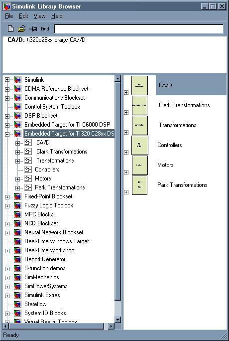
1 Technosoft is a Third Party of Texas Instruments supporting the TMS320C28xx and TMS320F24xx DSP controllers of the C2000 family To help you get your project started rapidly, Technosoft offers the DMCode-MS(BL) MATLAB Library A collection of motion control blocks usable to program Technosoft Motion Control Kits based on the TMS320F28335, TMS320F28035 or TMS320F2812 DSP controllers - You operate with a complete development environment, both at hardware and software levels. The solution offers many significant advantages, based on its typical features: Automatic C code generation: eliminates the need to handwrite C and Assembly code Visual modeling and simulation: selection of control structure, optimization of control parameters for specific application aspects Analysis on the DSP system: validation of the solution on the real control environment Plug-and-play approach: you get a ready-to-run platform. The first straightforward step is to set up the H/W and S/W; then you can already test that all parts operate properly (simulation, code generation, download and execution on DSP structure) In order to use the DMCode-MS(BL) MATLAB library you must have the following components of MATLAB installed on your PC: MATLAB Simulink Fixed-Point toolbox (for Matlab v7.x) or Fixed-Point Blockset (for Matlab v6.5) Real-Time Workshop Real-Time Workshop Embedded Coder Extended Target for TI320 C28xx DSP Library MATLAB-Simulink motion control library used to simulate different control models for synchronous and asynchronous motors. TI320C28xxLibrary: Simulink library model o Blocks for coordinate transformations o Blocks for PI and PID controllers o Blocks for A/D converters o Blocks for electrical motors 1/10
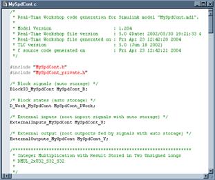


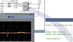

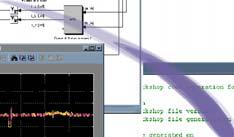
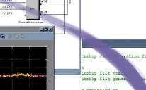

2 TI320C28xxtarget : target file used to generate C code for real time implementation Once the system has been simulated, and you are satisfied with its expected behavior, you can generate C/C++ code for the control blocks of the system, in order to implement and test it on the or 2812 DSP controller. Matlab-Simulink Real Time Workshop DMCD-Pro MCK2812 2/10
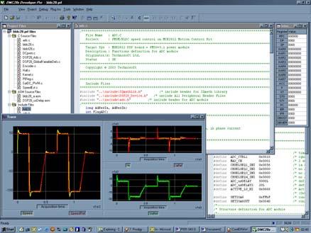
3 DMCD-Pro (Digital Motion Control Developer Pro) Digital Motion Control Developer for the integrated DSP software development with TMS320F28xx Incorporated Debugger Watch Windows Memory and I/O registers view / modify Integrated source code editor with powerful programming options Project Management System Tracing Module Plug-Ins Reference Generator Module Application Sources (Optional) Fully integrated DSP software development environment Windows environment with DSP-specific functions gets you started quickly Incorporated Debugger Observe / edit global variables during the debugging process Breakpoints, single stepping, stopping and continuing the current program View / edit of both data and program memory contents of the DSP target board Disassembly window with disassembled instructions with symbolic information for an effective debugging View / edit of I/O and internal registers of the DSP processor Integrated source code editor with powerful programming options Each file has its own window, and you can edit several views of the same file Advanced search and replace mechanism Syntax coloring for C and ASM (TI s assembly syntax is also supported) Bookmarks management Project Management System The system provides an effective way of quickly visualizing, accessing, and manipulating all the project files and their dependencies. The result is a concise, highly organized project management system that promotes a very efficient development process. Tracing module The system provides an advanced graphical tool for the analysis and evaluation of motion control applications. The program variables may be stored during the real-time execution of the motion, and then uploaded and visualized in the graphical environment. Plug-ins This module allows you to use external module functions in your DSP applications. Basically, you may select one or more external modules from a list containing all available external modules. If the reference generator plug-in is included in your application, you may define the motion reference at a high level in DMC Developer, download it, and execute it automatically on the DSP board. 3/10

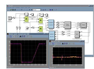
4 Brushless DC motion demo application Real time control method of driving the three-phase brushless motor The DMCode-MS(BL) library contains besides the MATLAB system model, complete TMS320F28335 or TMS320F2812 applications structured as projects of the DMCD-Pro platform. The complete source files of the application are included in the project structure. The application is the position or the speed control of a brushless motor operating in sinusoidal mode. The BL_SPD application speed control scheme is presented in the figure below. As can be seen, the scheme is based on the measure of two-phase currents and of the motor position. The speed estimator block is a simple encoder position difference block over one sampling period of the speed control loop. The measured phase currents, ia and ib, are transformed into the stator reference frame components, ids and iqs. Then, based on the position information, these components are transformed into the direct and quadrature rotor frame components, ide and iqe. The speed and current controllers are PI discrete controllers. The inverse coordinates transformation is used for the computation of the phase voltage references, v*as, v*bs and v*cs, applied to the inverter, starting from the voltage reference values computed in the d and q reference frames (v*de, v*qe). Thus, the program, based on these reference voltages, directly drives the 6 full-compare PWM outputs of the DSP controller. The direct current component reference, i*de, is set to 0 case corresponding to the motion of the motor in the normal speed range, without considering a possible field weakening operation. Based on this application that represents a complete ready-to-run motion example, you get all the information you need in order to understand its basic DSP implementation aspects, as well as a convenient starting point for the development of your own applications. The code is developed only in C language, both for the main structure of the application and for the timecritical parts as controllers, coordinates transformations, etc. 4/10
5 r * + - r Spd. Ctrl. I*de=0 + - I m * + - Crt Ctrl Crt Ctrl v* qe v* de d e, q e d s, q s V ds V qs d s, q s a, b, c v as * v bs * v cs * PWM Inverter MS 3~ TP m i qe d e, q e i ds d s, q s i a i b i de Speed Estimatior d s, q s i qs a, b, c The complete system can be simulated in the MATLAB-Simulink model provided with the library. The model includes motor, sensors and power converter, as well as digital control part (coordinates transformations, current, speed/position controllers, etc.). For the digital part, IQ-Math fixed-point computations are also included in the model. Blocks that are outlined in the previous figure can be selected to generate the corresponding C-code from MATLAB, and include and execute it in the DSP application project. Using the advanced features of DMCD-Pro, the motion reference can be defined at a high level, from the Windows environment. Calling the data logger function allows you to visualize any of the global variables of the program, and to effectively analyze and debug your application (time-critical parts as: controllers, coordinate transformations, etc.). The C code contains all the initialization routines, as well as the main kernel of the application. This offers maximum readability of the software structure. It will be easy for the user to understand the program functionality, as well as to modify, remove or add new functions in this configuration, for the customization of the application for specific cases. The C code also contains all the functions called in the real-time interrupt routines. 5/10
![Library block description The Motor Library Name: DC Motor Function: Models the operation of a DC (brushed) motor - [rad/s]: motor speed - M [Nm]: active motor torque Name: Induction Motor Function:](/docs-images/78/76770962/images/6-0.jpg "Models the operation of a 3-phased induction motor - Voltage command [V]: voltage applied to the motor - Mr [Nm]: resistive torque applied to the motor - position [rad]: motor position - speed")
![[rad/s]: motor speed - current [A]: motor current - M [Nm]: active motor torque Name: Synchronous Motor Function: Models the operation of a 3-phased permanent magnet synchronous motor - u_a [V]:](/docs-images/78/76770962/images/6-1.jpg "supply voltage applied to phase A of the motor - u_b [V]: supply voltage applied to phase B of the motor - u_c [V]: supply voltage applied to phase C of the motor - Mr [V]: resistive torque applied")
![to the motor - i_a [A]: the current on phase A of the motor - i_b [A]: the current on phase B of the motor - i_c [A]: the current on phase C of the motor - Ma [Nm]: active torque applied to the motor](/docs-images/78/76770962/images/6-2.jpg "- Phi_ra [Nm]: rotor flux of the motor - [rad/s]: motor speed - [rad]: motor position The AD Library Name: Current Measurement Function: Models the operation of the interface measuring the motor")
![currents - u_a [V]: supply voltage applied to phase A of the motor - u_b [V]: supply voltage applied to phase B of the motor - u_c [V]: supply voltage applied to phase C of the motor - Mr [V] :](/docs-images/78/76770962/images/6-3.jpg "resistive torque applied to the motor - i_a [A]: the current on phase A of the motor - i_b [A]: the current on phase B of the motor - i_c [A]: the current on phase C of the motor - [rad]: motor")
6 Library block description The Motor Library Name: DC Motor Function: Models the operation of a DC (brushed) motor - [rad/s]: motor speed - M [Nm]: active motor torque Name: Induction Motor Function: Models the operation of a 3-phased induction motor - Voltage command [V]: voltage applied to the motor - Mr [Nm]: resistive torque applied to the motor - position [rad]: motor position - speed [rad/s]: motor speed - current [A]: motor current - M [Nm]: active motor torque Name: Synchronous Motor Function: Models the operation of a 3-phased permanent magnet synchronous motor - u_a [V]: supply voltage applied to phase A of the motor - u_b [V]: supply voltage applied to phase B of the motor - u_c [V]: supply voltage applied to phase C of the motor - Mr [V]: resistive torque applied to the motor - i_a [A]: the current on phase A of the motor - i_b [A]: the current on phase B of the motor - i_c [A]: the current on phase C of the motor - Ma [Nm]: active torque applied to the motor - Phi_ra [Nm]: rotor flux of the motor - [rad/s]: motor speed - [rad]: motor position The AD Library Name: Current Measurement Function: Models the operation of the interface measuring the motor currents - u_a [V]: supply voltage applied to phase A of the motor - u_b [V]: supply voltage applied to phase B of the motor - u_c [V]: supply voltage applied to phase C of the motor - Mr [V] : resistive torque applied to the motor - i_a [A]: the current on phase A of the motor - i_b [A]: the current on phase B of the motor - i_c [A]: the current on phase C of the motor - [rad]: motor position - i_a [A]: real IA motor current - i_b [A]: real IB motor current - i_a [bit]: digital value of the IA current - i_b [bit]: digital value of the IB current - i_c [bit]: digital value of the IC current 6/10

 coordinates to (d,q) coordinates.")
![- [rad/s]: real motor position (an analogic measure). - [bit/sampling]: motor speed, estimated from the position variation for 1 sampling period - [bit]: motor position measured in encoder pulses.](/docs-images/78/76770962/images/7-2.jpg "This block estimates the motor position measured in encoder pulses, respectively the motor speed measured in encoder pulses, during one sampling period of the speed/position control loop.")
7 This block simulates the transformation of real currents read from the motor to digital values that are later used in the digital control scheme. Name: Incremental Encoder Function: Models the operation of an incremental-encoder type transducer and of the interface measuring the motor position. This block simulates the simplified model of the power converter used to supply the motors. Coordinate Transformation Block Library Name: TALPHABETA2DQ Function: Converts the motor current components from (, ) coordinates to (d,q) coordinates. - [rad/s]: real motor position (an analogic measure). - [bit/sampling]: motor speed, estimated from the position variation for 1 sampling period - [bit]: motor position measured in encoder pulses. This block estimates the motor position measured in encoder pulses, respectively the motor speed measured in encoder pulses, during one sampling period of the speed/position control loop. Name: Power Module Function: Models the operation of the power converter used to supply the motor - i_alpha [bit]: current component on the axis - i_beta [bit]: current component on the axis - sin(theta) [bit]: sine of electric angle - cos(theta) [bit]: cosine of electric angle - i_d [bit]: current component on the d axis - i_q [bit]: current component on the q axis This block represents the model of current transformation from the fixed (, ) system to the floating d-q system. Name: TDQ2ALPHABETA Function: Converts the voltage components from (d,q) coordinates to (, ) coordinates. - u_a_ref [bits]: phase A voltage input from the coordinate transformation block TDQ2ABC - u_b_ref [bits]: phase B voltage input from the coordinate transformation block TDQ2ABC - u_c_ref [bits]: phase C voltage input from the coordinate transformation block TDQ2ABC - u_a_ref [V]: real voltage applied to motor phase A - u_b_ref [V]: real voltage applied to motor phase B - u_c_ref [V]: real voltage applied to motor phase C - u_d [bit]: the reference voltage component on the d axis - u_q [bit]: the reference voltage component on the q axis - sin(theta) [bit]: sine of electric angle - cos(theta) [bit]: cosine of electric angle 7/10
![- u_alpha [bit]: voltage component on the axis - u_beta [bit]: voltage component on the axis.](/docs-images/78/76770962/images/8-0.jpg "This block represents the transformation model of input voltages from the d-q floating system to the fixed (, ) system.")


![- u_a [b]: reference voltage on phase A applied to the voltage amplifier - u_b [b]: reference voltage on phase B applied to the voltage amplifier - u_c [b]: reference voltage on phase C applied to](/docs-images/78/76770962/images/8-3.jpg "the voltage amplifier. This block represents the voltage transformation model from the fixed (, ) system to the fixed 3- phased system a,b,c.")
8 - u_alpha [bit]: voltage component on the axis - u_beta [bit]: voltage component on the axis. This block represents the transformation model of input voltages from the d-q floating system to the fixed (, ) system. Name: Tabo2ABC Function: Converts the voltage components from (, ) coordinates to (a,b,c) coordinates. B. - i_b [bit]: current measured on motor phase - i_alpha [bit]: axis current component - i_0 [bit]: homopolar current component - i_beta [bit]: axis current component This block represents the current transformation model from the fixed 3-phased a,b,c system, to the fixed (, ) system. Name: TDQ2ABC Function: Converts the voltage components from (d,q) coordinates to (a,b,c) coordinates. - u_alpha [bit]: voltage component on the axis. - u_beta [bit]: voltage component on the axis. - u_a [b]: reference voltage on phase A applied to the voltage amplifier - u_b [b]: reference voltage on phase B applied to the voltage amplifier - u_c [b]: reference voltage on phase C applied to the voltage amplifier. This block represents the voltage transformation model from the fixed (, ) system to the fixed 3- phased system a,b,c. Name: TABC2abo Function: Converts the current components from (a,b,c) coordinates to (, ) coordinates. - u_q_ref [bit]: reference voltage component on the q axis - u_d_ref [bit]: reference voltage component on the d axis. - sin(theta) [bit]: sine of electric angle. - cos(theta) [bit]: cosine of electric angle. - u_a_ref [V]: voltage on phase A applied to the voltage amplifier - u_b_ref [V]: voltage on phase B applied to the voltage amplifier - u_c_ref [V]: voltage on phase C applied to the voltage amplifier This block represents the voltage transformation model from the d-q rotor system, to the fixed a,b,c system. Name: TABC2DQ Function: Converts the current components from (a,b,c) coordinates to (d,q) coordinates. - i_a [bit]: current measured on motor phase A 8/10
9 - i_a [bit]: current on phase A of the motor - i_b [bit]: current on phase B of the motor - sin(theta) [bit]: sine of electric angle. - cos(theta) [bit]: cosine of electric angle. - i_d [b]: d axis current component - i_q [b]: q axis current component This block represents the coordinate transformation model from the fixed 3-phased a,b,c system, to the d-q rotor system. Controller Library Name: PI_controller Function: Digital controller of the PI type (used for speed or current control, on d or q axes) - Reference [bit]: imposed reference value. Depending on the controller s use, it can be: position, speed, or current in d or q axis. - Feedback [bit]: measured value of the controlled variable. Depending on the controller s use, it can be: position, speed, or current in d or q axis. - Command [bit]: This parameter can be: A speed reference if the PI controller is used as a position controller A current reference (q component) if the PI is used as a speed controller A voltage reference (d or q) if the PI is used as a current controller (d or q) This block implements a PI controller. The controller s variable parameters are: Kp (proportional component), Ki (integral component), as well as the saturation parameters of the controller output. Name: PID_controller Function: Digital controller of the PID type (used for position control) - Reference [bit]: imposed reference value - Feedback [bit]: measured motor position - Command [bit]: This parameter can be: speed reference for the speed controller current reference for the current controller This block implements a PID controller. The controller s variable parameters are: Kd (derivative component), Kp (proportional component), Ki (integral component), sampling rate, integral limit, as well as the saturation parameters of the controller output. Name: SLIP Function: Compute the slip between the stator and rotor fields - mec [bit]: motor speed - i_q [bit]: the current on the q axis of the motor. - theta [bit]: electric angle between phase A and the d axis of the rotor flux. This block is only used for induction motor control schemes. The adjustable parameters of this block are: c_slip (slip increment) and c_spd (speed increment) 9/10
10 10/10
Impact of PWM Control Frequency onto Efficiency of a 1 kw Permanent Magnet Synchronous Motor
 http://dx.doi.org/10.5755/j01.eie.22.6.17216 ELEKTRONIKA IR ELEKTROTECHNIKA, ISSN 1392-1215, VOL. 22, NO. 6, 2016 Impact of PWM Control Frequency onto Efficiency of a 1 kw Permanent Magnet Synchronous
RX23T inverter ref. kit
 RX23T inverter ref. kit Deep Dive October 2015 YROTATE-IT-RX23T kit content Page 2 YROTATE-IT-RX23T kit: 3-ph. Brushless Motor Specs Page 3 Motors & driving methods supported Brushless DC Permanent Magnet
User Guide IRMCS3041 System Overview/Guide. Aengus Murray. Table of Contents. Introduction
 User Guide 0607 IRMCS3041 System Overview/Guide By Aengus Murray Table of Contents Introduction... 1 IRMCF341 Application Circuit... 2 Sensorless Control Algorithm... 4 Velocity and Current Control...
Sensors and Sensing Motors, Encoders and Motor Control
 Sensors and Sensing Motors, Encoders and Motor Control Todor Stoyanov Mobile Robotics and Olfaction Lab Center for Applied Autonomous Sensor Systems Örebro University, Sweden todor.stoyanov@oru.se 13.11.2014
National Infotech. Electrical Drive Trainers. Developed By: : Authorized Dealer : Embedded System Solutions
 National Infotech A way to Power Electronics and Embedded System Solutions Electrical Drive Trainers In every industry there are industrial processes where electrical motors are used as a part of process
STM32 PMSM FOC SDK v3.2. 蒋建国 MCU Application Great China
 STM32 PMSM FOC SDK v3.2 蒋建国 MCU Application Great China Agenda 2 1 st day Morning Overview Key message Basics Feature Performance Hardware support Tools STM32 MC Workbench SDK components Architectural
ANALYSIS OF V/f CONTROL OF INDUCTION MOTOR USING CONVENTIONAL CONTROLLERS AND FUZZY LOGIC CONTROLLER
 ANALYSIS OF V/f CONTROL OF INDUCTION MOTOR USING CONVENTIONAL CONTROLLERS AND FUZZY LOGIC CONTROLLER Archana G C 1 and Reema N 2 1 PG Student [Electrical Machines], Department of EEE, Sree Buddha College
User Guide Introduction. IRMCS3043 System Overview/Guide. International Rectifier s imotion Team. Table of Contents
 User Guide 08092 IRMCS3043 System Overview/Guide By International Rectifier s imotion Team Table of Contents IRMCS3043 System Overview/Guide... 1 Introduction... 1 IRMCF343 Application Circuit... 2 Power
Simulation and Dynamic Response of Closed Loop Speed Control of PMSM Drive Using Fuzzy Controller
 Simulation and Dynamic Response of Closed Loop Speed Control of PMSM Drive Using Fuzzy Controller Anguru Sraveen Babu M.Tech Student Scholar Dept of Electrical & Electronics Engineering, Baba Institute
Vector Control of a 3-Phase PMSM Using the ZNEO Z16FMC MCU
 MultiMotor Series Application Note Vector Control of a 3-Phase PMSM Using the ZNEO Z16FMC MCU AN039402-0816 Abstract Brushed DC machines are widely popular due to their simplicity, ease of control and
A COMPARISON STUDY OF THE COMMUTATION METHODS FOR THE THREE-PHASE PERMANENT MAGNET BRUSHLESS DC MOTOR
 A COMPARISON STUDY OF THE COMMUTATION METHODS FOR THE THREE-PHASE PERMANENT MAGNET BRUSHLESS DC MOTOR Shiyoung Lee, Ph.D. Pennsylvania State University Berks Campus Room 120 Luerssen Building, Tulpehocken
Motor control using FPGA
 Motor control using FPGA MOTIVATION In the previous chapter you learnt ways to interface external world signals with an FPGA. The next chapter discusses digital design and control implementation of different
Sensorless Vector Control and Implementation: Why and How
 Sensorless Vector Control and Implementation: Why and How Renesas Electronics America Inc. Renesas Technology & Solution Portfolio 2 Microcontroller and Microprocessor Line-up 2010 2013 32-bit 8/16-bit
Volume 1, Number 1, 2015 Pages Jordan Journal of Electrical Engineering ISSN (Print): , ISSN (Online):
: , ISSN (Online):") JJEE Volume, Number, 2 Pages 3-24 Jordan Journal of Electrical Engineering ISSN (Print): 249-96, ISSN (Online): 249-969 Analysis of Brushless DC Motor with Trapezoidal Back EMF using MATLAB Taha A. Hussein
JJEE Volume, Number, 2 Pages 3-24 Jordan Journal of Electrical Engineering ISSN (Print): 249-96, ISSN (Online): 249-969 Analysis of Brushless DC Motor with Trapezoidal Back EMF using MATLAB Taha A. Hussein
Analog Devices: High Efficiency, Low Cost, Sensorless Motor Control.
 Analog Devices: High Efficiency, Low Cost, Sensorless Motor Control. Dr. Tom Flint, Analog Devices, Inc. Abstract In this paper we consider the sensorless control of two types of high efficiency electric
SPEED CONTROL OF BRUSHLESS DC MOTOR USING FUZZY BASED CONTROLLERS
 SPEED CONTROL OF BRUSHLESS DC MOTOR USING FUZZY BASED CONTROLLERS Kapil Ghuge 1, Prof. Manish Prajapati 2 Prof. Ashok Kumar Jhala 3 1 M.Tech Scholar, 2 Assistant Professor, 3 Head of Department, R.K.D.F.
ECE 5670/ Lab 5. Closed-Loop Control of a Stepper Motor. Objectives
 1. Introduction ECE 5670/6670 - Lab 5 Closed-Loop Control of a Stepper Motor Objectives The objective of this lab is to develop and test a closed-loop control algorithm for a stepper motor. First, field
32-Bit-Digital Signal Controller TMS320F2812
 Module 15 : C28x Digital Motor Control 32-Bit-Digital ignal Controller TM320F2812 Texas Instruments Incorporated European Customer Training Centre Uniersity of Applied ciences Zwickau (FH) 15-1 Electrical
CHAPTER 6 CURRENT REGULATED PWM SCHEME BASED FOUR- SWITCH THREE-PHASE BRUSHLESS DC MOTOR DRIVE
 125 CHAPTER 6 CURRENT REGULATED PWM SCHEME BASED FOUR- SWITCH THREE-PHASE BRUSHLESS DC MOTOR DRIVE 6.1 INTRODUCTION Permanent magnet motors with trapezoidal back EMF and sinusoidal back EMF have several
Modelling and Simulation of a DC Motor Drive
 Modelling and Simulation of a DC Motor Drive 1 Introduction A simulation model of the DC motor drive will be built using the Matlab/Simulink environment. This assignment aims to familiarise you with basic
Page ENSC387 - Introduction to Electro-Mechanical Sensors and Actuators: Simon Fraser University Engineering Science
 Motor Driver and Feedback Control: The feedback control system of a dc motor typically consists of a microcontroller, which provides drive commands (rotation and direction) to the driver. The driver is
The University of Wisconsin-Platteville
 Embedded Motor Drive Development Platform for Undergraduate Education By: Nicholas, Advisor Dr. Xiaomin Kou This research and development lead to the creation of an Embedded Motor Drive Prototyping station
EE152 Final Project Report
 LPMC (Low Power Motor Controller) EE152 Final Project Report Summary: For my final project, I designed a brushless motor controller that operates with 6-step commutation with a PI speed loop. There are
FOR the last decade, many research efforts have been made
 IEEE TRANSACTIONS ON POWER ELECTRONICS, VOL. 19, NO. 6, NOVEMBER 2004 1601 A Novel Approach for Sensorless Control of PM Machines Down to Zero Speed Without Signal Injection or Special PWM Technique Chuanyang
RAPID CONTROL PROTOTYPING FOR ELECTRIC DRIVES
 RAPID CONTROL PROTOTYPING FOR ELECTRIC DRIVES Lukáš Pohl Doctoral Degree Programme (2), FEEC BUT E-mail: xpohll01@stud.feec.vutbr.cz Supervised by: Petr Blaha E-mail: blahap@feec.vutbr.cz Abstract: This
A Complete Implementation Procedure for State Estimation in Induction Machines on the ezdsp F2812. Ali M. Bazzi and Philip T.
 A Complete Implementation Procedure for State Estimation in Induction Machines on the ezdsp F2812 Ali M. Bazzi and Philip T. Krein Grainger Center for Electric Machinery and Electromechanics Department
Design of stepper motor position control system based on DSP. Guan Fang Liu a, Hua Wei Li b
 nd International Conference on Machinery, Electronics and Control Simulation (MECS 17) Design of stepper motor position control system based on DSP Guan Fang Liu a, Hua Wei Li b School of Electrical Engineering,
Simulation and Dynamic Response of Closed Loop Speed Control of PMSM Drive Using Fuzzy Controller
 Simulation and Dynamic Response of Closed Loop Speed Control of PMSM Drive Using Fuzzy Controller Anguru Sraveen Babu M.Tech Student Scholar Department of Electrical & Electronics Engineering, Baba Institute
CHAPTER 6 UNIT VECTOR GENERATION FOR DETECTING VOLTAGE ANGLE
 98 CHAPTER 6 UNIT VECTOR GENERATION FOR DETECTING VOLTAGE ANGLE 6.1 INTRODUCTION Process industries use wide range of variable speed motor drives, air conditioning plants, uninterrupted power supply systems
VECTOR CONTROL SCHEME FOR INDUCTION MOTOR WITH DIFFERENT CONTROLLERS FOR NEGLECTING THE END EFFECTS IN HEV APPLICATIONS
 VECTOR CONTROL SCHEME FOR INDUCTION MOTOR WITH DIFFERENT CONTROLLERS FOR NEGLECTING THE END EFFECTS IN HEV APPLICATIONS M.LAKSHMISWARUPA 1, G.TULASIRAMDAS 2 & P.V.RAJGOPAL 3 1 Malla Reddy Engineering College,
CHAPTER 2 STATE SPACE MODEL OF BLDC MOTOR
 29 CHAPTER 2 STATE SPACE MODEL OF BLDC MOTOR 2.1 INTRODUCTION Modelling and simulation have been an essential part of control system. The importance of modelling and simulation is increasing with the combination
Sensors and Sensing Motors, Encoders and Motor Control
 Sensors and Sensing Motors, Encoders and Motor Control Todor Stoyanov Mobile Robotics and Olfaction Lab Center for Applied Autonomous Sensor Systems Örebro University, Sweden todor.stoyanov@oru.se 05.11.2015
International Journal of Digital Application & Contemporary research Website: (Volume 2, Issue 8, March 2014)
") Field Oriented Control of PMSM Using Improved Space Vector Modulation Technique Yeshwant Joshi Kapil Parikh Dr. Vinod Kumar Yadav yshwntjoshi@gmail.com kapilparikh@ymail.com vinodcte@yahoo.co.in Abstract:
Field Oriented Control of PMSM Using Improved Space Vector Modulation Technique Yeshwant Joshi Kapil Parikh Dr. Vinod Kumar Yadav yshwntjoshi@gmail.com kapilparikh@ymail.com vinodcte@yahoo.co.in Abstract:
BLuAC5 Brushless Universal Servo Amplifier
 BLuAC5 Brushless Universal Servo Amplifier Description The BLu Series servo drives provide compact, reliable solutions for a wide range of motion applications in a variety of industries. BLu Series drives
SPEED CONTROL OF INDUCTION MOTOR WITHOUT SPEED SENSOR AT LOW SPEED OPERATIONS
 SPEED CONTROL OF INDUCTION MOTOR WITHOUT SPEED SENSOR AT LOW SPEED OPERATIONS Akshay Prasad Dubey and Saravana Kumar R. School of Electrical Engineering, VIT University, Vellore, Tamil Nadu, India E-Mail:
Design and implementation of Open & Close Loop Speed control of Three Phase Induction Motor Using PI Controller
 Design and implementation of Open & Close Loop Speed control of Three Phase Induction Motor Using PI Controller Ibtisam Naveed 1, Adnan Sabir 2 1 (Electrical Engineering, NFC institute of Engineering and
Modeling and Simulation of Induction Motor Drive with Space Vector Control
 Australian Journal of Basic and Applied Sciences, 5(9): 2210-2216, 2011 ISSN 1991-8178 Modeling and Simulation of Induction Motor Drive with Space Vector Control M. SajediHir, Y. Hoseynpoor, P. MosadeghArdabili,
Reduction of Harmonics and Torque Ripples of BLDC Motor by Cascaded H-Bridge Multi Level Inverter Using Current and Speed Control Techniques
 Reduction of Harmonics and Torque Ripples of BLDC Motor by Cascaded H-Bridge Multi Level Inverter Using Current and Speed Control Techniques A. Sneha M.Tech. Student Scholar Department of Electrical &
Chapter 12 DSP-BASED CONTROL OF PERMANENT MAGNET SYNCHRONOUS MACHINES
 Chapter 1 DSP-BASED CONTROL OF PERMANENT MAGNET SYNCHRONOUS MACHINES 1.1 Introduction As described in Chapter 9, the permanent magnet synchronous motor (PMSM) is a PM motor with a sinusoidal back-emf.
Advanced Digital Motion Control Using SERCOS-based Torque Drives
 Advanced Digital Motion Using SERCOS-based Torque Drives Ying-Yu Tzou, Andes Yang, Cheng-Chang Hsieh, and Po-Ching Chen Power Electronics & Motion Lab. Dept. of Electrical and Engineering National Chiao
CHAPTER 4 CONTROL ALGORITHM FOR PROPOSED H-BRIDGE MULTILEVEL INVERTER
 65 CHAPTER 4 CONTROL ALGORITHM FOR PROPOSED H-BRIDGE MULTILEVEL INVERTER 4.1 INTRODUCTION Many control strategies are available for the control of IMs. The Direct Torque Control (DTC) is one of the most
ECE 5670/ Lab 6. Parameter Estimation of a Brushless DC Motor. Objectives
 ECE 5670/6670 - Lab 6 Parameter Estimation of a Brushless DC Motor Objectives The objective of the lab is to determine the parameters of a brushless DC motor and to experiment with control strategies using
DSP Based Speed Control of the Surface Mounted Permanent Magnet Synchronous Motor with Hysteresis current controller
 DSP Based Speed Control of the Surface Mounted Permanent Magnet Synchronous Motor with Hysteresis current controller ABDEL-KARIM DAUD Electrical and Computer Engineering Department Palestine Polytechnic
CHAPTER 4 HARDWARE DEVELOPMENT OF STATCOM
 74 CHAPTER 4 HARDWARE DEVELOPMENT OF STATCOM 4.1 LABORATARY SETUP OF STATCOM The laboratory setup of the STATCOM consists of the following hardware components: Three phase auto transformer used as a 3
BLuAC5 Brushless Universal Servo Amplifier
 BLuAC5 Brushless Universal Servo Amplifier Description The BLu Series servo drives provide compact, reliable solutions for a wide range of motion applications in a variety of industries. BLu Series drives
Modeling & Simulation of PMSM Drives with Fuzzy Logic Controller
 Vol. 3, Issue. 4, Jul - Aug. 2013 pp-2492-2497 ISSN: 2249-6645 Modeling & Simulation of PMSM Drives with Fuzzy Logic Controller Praveen Kumar 1, Anurag Singh Tomer 2 1 (ME Scholar, Department of Electrical
Techniques for Implementing a Model Simulated on a Physical Drive Vector Control
 3 rd International Sympoium on Electrical Engineering and Energy er September 24-25, 2009, Suceava Technique for Implementing a Model Simulated on a Phyical Drive Vector Control Ciprian AFANASOV "Stefan
A Practical Primer On Motor Drives (Part 13): Motor Drive Control Architectures And Algorithms
: Motor Drive Control Architectures And Algorithms") ISSUE: February 2017 A Practical Primer On Motor Drives (Part 13): Motor Drive Control Architectures And Algorithms by Ken Johnson, Teledyne LeCroy, Chestnut Ridge, N.Y. Part 12 began the explanation of
ISSUE: February 2017 A Practical Primer On Motor Drives (Part 13): Motor Drive Control Architectures And Algorithms by Ken Johnson, Teledyne LeCroy, Chestnut Ridge, N.Y. Part 12 began the explanation of
Example Data for Electric Drives Experiment 6. Analysis and Control of a Permanent Magnet AC (PMAC) Motor
 Motor") Example Data for Electric Drives Experiment 6 Analysis and Control of a Permanent Magnet AC (PMAC) Motor The intent of this document is to provide example data for instructors and TAs, to help them prepare
Example Data for Electric Drives Experiment 6 Analysis and Control of a Permanent Magnet AC (PMAC) Motor The intent of this document is to provide example data for instructors and TAs, to help them prepare
A Low Torque Ripple PMSM Drive for EPS Applications
 A Low Torque Ripple PMSM Drive for EPS Applications Guang Liu, Alex Kurnia, Ronan De Larminat, Phil Desmond and Tony O Gorman Automotive Communications & Electronics Systems Group Motorola Inc. 2144 West
Design and Implementation of a Three-Phase Boost Battery Charger with PFC using CompactRIO Control System
 Design and Implementation of a Three-Phase Boost Battery Charger with PFC using CompactRIO Control System Master of Science Thesis in Electric Power Engineering Daniel Castro Carmona Javier Fernández Mandiola
Digital Control of Permanent Magnet Synchronous Motor
 Digital Control of Permanent Magnet Synchronous Motor Jayasri R. Nair 1 Assistant Professor, Dept. of EEE, Rajagiri School Of Engineering and Technology, Kochi, Kerala, India 1 ABSTRACT: The principle
Induction motor control by vector control method.
 International Refereed Journal of Engineering and Science (IRJES) e- ISSN :2319-183X p-issn : 2319-1821 On Recent Advances in Electrical Engineering Induction motor control by vector control method. Miss.
Type of loads Active load torque: - Passive load torque :-
 Type of loads Active load torque: - Active torques continues to act in the same direction irrespective of the direction of the drive. e.g. gravitational force or deformation in elastic bodies. Passive
Improving INFORM calculation method on permanent magnet synchronous machines
 IMTC 27 - IEEE Instrumentation and Measurement Technology Conference Warsaw, Poland, May 1-3, 27 Improving INFORM calculation method on permanent magnet synchronous machines A. Zentail and T. Daboczi2
ELE847 Advanced Electromechanical Systems Course Notes 2008 Edition
 Department of Electrical and Computer Engineering ELE847 Advanced Electromechanical Systems Course Notes 2008 Edition ELE847 Advanced Electromechanical Systems Table of Contents 1. Course Outline.... 1
CHAPTER-5 DESIGN OF DIRECT TORQUE CONTROLLED INDUCTION MOTOR DRIVE
 113 CHAPTER-5 DESIGN OF DIRECT TORQUE CONTROLLED INDUCTION MOTOR DRIVE 5.1 INTRODUCTION This chapter describes hardware design and implementation of direct torque controlled induction motor drive with
The Research on Servo Control System for AC PMSM Based on DSP BaiLei1, a, Wengang Zheng2, b
 4th International Conference on Mechatronics, Materials, Chemistry and Computer Engineering (ICMMCCE 015) The Research on Servo Control System for AC PMSM Based on DSP BaiLei1, a, Wengang Zheng, b 1 Engineering
Brushless DC motor drive board evaluation
 Brushless DC motor drive board evaluation Version: Friday, March 14, 2014 Applies to: SAT0042 E4 brushless DC motor drive board 1 Initial Evaluation 1.1 Visual inspection 1.1.1 Verify the components are
CHAPTER 2 CURRENT SOURCE INVERTER FOR IM CONTROL
 9 CHAPTER 2 CURRENT SOURCE INVERTER FOR IM CONTROL 2.1 INTRODUCTION AC drives are mainly classified into direct and indirect converter drives. In direct converters (cycloconverters), the AC power is fed
Galil Motion Control. DMC 3x01x. Datasheet
 Galil Motion Control DMC 3x01x Datasheet 1-916-626-0101 Galil Motion Control 270 Technology Way, Rocklin, CA [Type here] [Type here] (US ONLY) 1-800-377-6329 [Type here] Product Description The DMC-3x01x
Vector Control (Field Oriented Control, Direct Torque Control)
") Vector Control (Field Oriented Control, Direct Torque Control) Referents: Prof. Dr. Ing. Ralph Kennel (ralph.kennel@tum.de) Technische Universität München Arcisstraße 21 80333 München Germany 1 The General
Vector Control (Field Oriented Control, Direct Torque Control) Referents: Prof. Dr. Ing. Ralph Kennel (ralph.kennel@tum.de) Technische Universität München Arcisstraße 21 80333 München Germany 1 The General
2.017 DESIGN OF ELECTROMECHANICAL ROBOTIC SYSTEMS Fall 2009 Lab 4: Motor Control. October 5, 2009 Dr. Harrison H. Chin
 2.017 DESIGN OF ELECTROMECHANICAL ROBOTIC SYSTEMS Fall 2009 Lab 4: Motor Control October 5, 2009 Dr. Harrison H. Chin Formal Labs 1. Microcontrollers Introduction to microcontrollers Arduino microcontroller
Sistemi per il controllo motori
 Sistemi per il controllo motori TALENTIS 4ª SESSIONE - 28 MAGGIO 2018 Speaker: Ing. Giuseppe Scuderi Automation and Motion control team Central Lab Prodotti ST per il controllo motori 2 Applicazioni e
TUTORIAL Simulation and Code Generation of TI InstaSPIN Using DRV8312 EVM
 TUTORIAL Simulation and Code Generation of TI InstaSPIN Using DRV8312 EVM January 2017 1 PSIM supports TI s InstaSPIN FOC sensorless motor control algorithm in simulation and SimCoder auto code generation.
2014 Texas Instruments Motor Control Training Series. -V th. Dave Wilson
 2014 Texas Instruments Motor Control Training Series -V th Evolution of Sensorless Drive Technology March, 2013 InstaSPIN-FOC Saliency Tracking Direct Torque Control Sliding Mode Observers Linear Observers
Active Vibration Isolation of an Unbalanced Machine Tool Spindle
 Active Vibration Isolation of an Unbalanced Machine Tool Spindle David. J. Hopkins, Paul Geraghty Lawrence Livermore National Laboratory 7000 East Ave, MS/L-792, Livermore, CA. 94550 Abstract Proper configurations
AN2290 Application note Flux control simulink and software library of a PMSM Introduction
 Application note Flux control simulink and software library of a PMSM Introduction This application note describes a software library for the electric motor control implementing a (FOC) Flux Oriented Control
DSP BASED SYSTEM FOR SYNCHRONOUS GENERATOR EXCITATION CONTROLL
 DSP BASED SYSTEM FOR SYNCHRONOUS GENERATOR EXCITATION CONTROLL N. Bulic *, M. Miletic ** and I.Erceg *** Faculty of electrical engineering and computing Department of Electric Machines, Drives and Automation,
A HARDWARE DC MOTOR EMULATOR VAGNER S. ROSA 1, VITOR I. GERVINI 2, SEBASTIÃO C. P. GOMES 3, SERGIO BAMPI 4
 A HARDWARE DC MOTOR EMULATOR VAGNER S. ROSA 1, VITOR I. GERVINI 2, SEBASTIÃO C. P. GOMES 3, SERGIO BAMPI 4 Abstract Much work have been done lately to develop complex motor control systems. However they
HIGH PERFORMANCE CONTROL OF AC DRIVES WITH MATLAB/SIMULINK MODELS
 HIGH PERFORMANCE CONTROL OF AC DRIVES WITH MATLAB/SIMULINK MODELS Haitham Abu-Rub Texas A&M University at Qatar, Qatar Atif Iqbal Qatar University, Qatar and Aligarh Muslim University, India Jaroslaw Guzinski
ANALYSIS OF POWER QUALITY IMPROVEMENT OF BLDC MOTOR DRIVE USING CUK CONVERTER OPERATING IN DISCONTINUOUS CONDUCTION MODE
 ANALYSIS OF POWER QUALITY IMPROVEMENT OF BLDC MOTOR DRIVE USING CUK CONVERTER OPERATING IN DISCONTINUOUS CONDUCTION MODE Bhushan P. Mokal 1, Dr. K. Vadirajacharya 2 1,2 Department of Electrical Engineering,Dr.
Comparative Analysis of PI Controller and Fuzzy Logic Controller for Speed Control of Three Phase Induction Motor Drive
 Comparative Analysis of PI Controller and Fuzzy Logic Controller for Speed Control of Three Phase Induction Motor Drive Manjunatha M N, M.Tech, Dept. of Electrical and Electronics KVGCE Sullia, Karanataka,
STM32 motor control firmware library. STM32 FOC PMSM SDK v3.0.
 STM32 motor control firmware library STM32 FOC PMSM SDK v3.0 Contents STM32 FOC PMSM SDK v3.0 overview The FOC (field oriented control) algorithm STM32 with FOC Motor control and electric motor offer FOC
AC Drive Technology. An Overview for the Converting Industry. Siemens Industry, Inc All rights reserved.
 AC Drive Technology An Overview for the Converting Industry www.usa.siemens.com/converting Siemens Industry, Inc. 2016 All rights reserved. Answers for industry. AC Drive Technology Drive Systems AC Motors
Section CSI non-slaient pole synchronous motor drive
 Section 4.4 - CS non-slaient pole synchronous motor drive 4.4.1 Perormance with current-source inverter (CS) drive Current-source driven synchronous motor drives generally give higher dynamic response
CHAPTER 3 WAVELET TRANSFORM BASED CONTROLLER FOR INDUCTION MOTOR DRIVES
 49 CHAPTER 3 WAVELET TRANSFORM BASED CONTROLLER FOR INDUCTION MOTOR DRIVES 3.1 INTRODUCTION The wavelet transform is a very popular tool for signal processing and analysis. It is widely used for the analysis
A Modified Sychronous Current Regulator for Brushless Motor Control
 A Modified Sychronous Current Regulator for Brushless Motor Control Shane Colton Graduate Student, Department of Mechanical Engineering Massachusetts Institute of Technology Rev0 - Doctoral
Chapter 2 MODELING AND CONTROL OF PEBB BASED SYSTEMS
 Chapter 2 MODELING AND CONTROL OF PEBB BASED SYSTEMS 2.1 Introduction The PEBBs are fundamental building cells, integrating state-of-the-art techniques for large scale power electronics systems. Conventional
Design of Joint Controller Circuit for PA10 Robot Arm
 Design of Joint Controller Circuit for PA10 Robot Arm Sereiratha Phal and Manop Wongsaisuwan Department of Electrical Engineering, Faculty of Engineering, Chulalongkorn University, Bangkok, 10330, Thailand.
3KDVH 6LQH *HQHUDWRU ZLWK 9DULDEOH3KDVH&RQWURO
 Digital Motor Control Library 3KDVH 6LQH *HQHUDWRU ZLWK 9DULDEOH3KDVH&RQWURO Component Name: 2-Phase Sine Generator with Variable Phase Control 2-Phase Sine Generator with Variable Phase Control 0 Inputs
MATLAB/SIMULINK MODEL OF FIELD ORIENTED CONTROL OF PMSM DRIVE USING SPACE VECTORS
 MATLAB/SIMULINK MODEL OF FIELD ORIENTED CONTROL OF PMSM DRIVE USING SPACE VECTORS Remitha K Madhu 1 and Anna Mathew 2 1 Department of EE Engineering, Rajagiri Institute of Science and Technology, Kochi,
DSP implementation for the axial flux motor
 DSP implementation for the axial flux motor J.A.G. Wouters 0529393 DCT 2007.056 Traineeship report Coach(es): Supervisor: G. Heins Dr. ir. F. de Boer Prof.dr.ir. M. Steinbuch Technische Universiteit Eindhoven
A New Approach for Synchronisation Multiple Motors using DSP
 A New Approach for Synchronisation Multiple Motors using DSP K. Boudjit and C. Larbes Abstract - A method for achieving the co-ordination and synchronisation of multiple motors on line using DSP is described.
Design of double loop-locked system for brush-less DC motor based on DSP
 International Conference on Advanced Electronic Science and Technology (AEST 2016) Design of double loop-locked system for brush-less DC motor based on DSP Yunhong Zheng 1, a 2, Ziqiang Hua and Li Ma 3
EE 4314 Lab 3 Handout Speed Control of the DC Motor System Using a PID Controller Fall Lab Information
 EE 4314 Lab 3 Handout Speed Control of the DC Motor System Using a PID Controller Fall 2012 IMPORTANT: This handout is common for all workbenches. 1. Lab Information a) Date, Time, Location, and Report
Synchronous Current Control of Three phase Induction motor by CEMF compensation
 Synchronous Current Control of Three phase Induction motor by CEMF compensation 1 Kiran NAGULAPATI, 2 Dhanamjaya Appa Rao, 3 Anil Kumar VANAPALLI 1,2,3 Assistant Professor, ANITS, Sangivalasa, Visakhapatnam,
SPEED CONTROL OF PERMANENT MAGNET SYNCHRONOUS MOTOR USING VOLTAGE SOURCE INVERTER
 SPEED CONTROL OF PERMANENT MAGNET SYNCHRONOUS MOTOR USING VOLTAGE SOURCE INVERTER Kushal Rajak 1, Rajendra Murmu 2 1,2 Department of Electrical Engineering, B I T Sindri, (India) ABSTRACT This paper presents
RL78 Motor Control. YRMCKITRL78G14 Starter Kit. Renesas Electronics Europe. David Parsons Application Engineering Industrial Business Group.
 RL78 Motor Control YRMCKITRL78G14 Starter Kit Renesas Electronics Europe David Parsons Application Engineering Industrial Business Group July 2012 Renesas MCU for 3-phase Motor Control Control Method Brushless
International Journal of Research In Science & Engineering e-issn: Volume: 3 Issue: 2 March-April 2017 p-issn:
 DSP BASED SPEED CONTROL OF DC MOTOR BY USING CASCADE SPEED CONTROL Mr. Snehal Dubey 1, Mr. Pratik Ghutke 2 Sr. Lecturer, K.R. PANDAV POLYTECHNIC Asst. Professor, Tulsiramji Gaikwad Patil College of Engg.
Feedback Devices. By John Mazurkiewicz. Baldor Electric
 Feedback Devices By John Mazurkiewicz Baldor Electric Closed loop systems use feedback signals for stabilization, speed and position information. There are a variety of devices to provide this data, such
Speed Control of Brushless DC Motor Using Fuzzy Based Controllers
 Speed Control of Brushless DC Motor Using Fuzzy Based Controllers Harith Mohan 1, Remya K P 2, Gomathy S 3 1 Harith Mohan, P G Scholar, EEE, ASIET Kalady, Kerala, India 2 Remya K P, Lecturer, EEE, ASIET
2013 Texas Instruments Motor Control Training Series. -V th. InstaSPIN Training
 2013 Texas Instruments Motor Control Training Series -V th InstaSPIN Training How Do You Control Torque on a DC Motor? Brush DC Motor Desire Current + - Error Signal PI Controller PWM Power Stage Texas
Control of Electric Machine Drive Systems
 Control of Electric Machine Drive Systems Seung-Ki Sul IEEE 1 PRESS к SERIES I 0N POWER ENGINEERING Mohamed E. El-Hawary, Series Editor IEEE PRESS WILEY A JOHN WILEY & SONS, INC., PUBLICATION Contents
L E C T U R E R, E L E C T R I C A L A N D M I C R O E L E C T R O N I C E N G I N E E R I N G
 P R O F. S L A C K L E C T U R E R, E L E C T R I C A L A N D M I C R O E L E C T R O N I C E N G I N E E R I N G G B S E E E @ R I T. E D U B L D I N G 9, O F F I C E 0 9-3 1 8 9 ( 5 8 5 ) 4 7 5-5 1 0
Fuzzy Logic Based Speed Control of BLDC Motor
 Fuzzy Logic Based Speed Control of BLDC Motor Mahesh Sutar #1, Ashish Zanjade *2, Pankaj Salunkhe #3 # EXTC Department, Mumbai University. 1 Sutarmahesh4@gmail.com 2 Zanjade_aa@rediffmail.com 3 pasalunkhe@gmail.com
Sensorless Vector Control with RL78G14
 Sensorless Vector Control with RL78G14 Renesas Electronics America Inc. Renesas Technology & Solution Portfolio 2 Microcontroller and Microprocessor Line-up 2010 2013 32-bit 8/16-bit 1200 DMIPS, Superscalar
Using Magnetic Sensors for Absolute Position Detection and Feedback. Kevin Claycomb University of Evansville
 Using Magnetic Sensors for Absolute Position Detection and Feedback. Kevin Claycomb University of Evansville Using Magnetic Sensors for Absolute Position Detection and Feedback. Abstract Several types
Applying POWERSYS and SIMULINK to Modeling Switched Reluctance Motor
 Tamkang Journal of Science and Engineering, Vol. 12, No. 4, pp. 429 438 (2009) 429 Applying POWERSYS and SIMULINK to Modeling Switched Reluctance Motor K. I. Hwu Institute of Electrical Engineering, National
Cuk Converter Fed BLDC Motor with a Sensorless Control Method
 Cuk Converter Fed BLDC Motor with a Sensorless Control Method Neethu Salim 1, Neetha John 2 1 PG Student, Department of EEE, Mar Athanasius College of Engineering, Kothamangalam, Kerala, India 2 Assistant