Installation Manual Console Integration System
|
|
|
- Coleen Kelly
- 6 years ago
- Views:
Transcription
1 Installation Manual Console Integration System Table of Contents Kit Contents... 2 Overview... 3 Installation Instructions... 3 Typical Installation Wiring Diagram... 4 Configuring the Network Bridge... 5 Beam Coverage... 6 Power up... 7 Test the System... 8 Connections... 9 Sequential Paging Formats Motorola Gold Elite Audio Level Trouble Shooting Tips Notes

2 Kit Contents Description Qty SATRAD-CIS Console Integration System 1 Power cord 1 2
3 Overview This manual provides instructions for the installation and testing of the console integration system. The system was designed to augment existing dispatch centers with a satellite back up for terrestrial communications. Installation of this device should be performed by certified installers with communications experience. Installation Instructions 1. Ensure that all items in the contents list are present. 2. Check for any visible damage to components. 3. Select an area on the existing communications system racking. The unit takes up 1U of space in a 19inch rack. 4. Bolt the CIS unit into the rack frame. 5. Locate an electrical outlet and plug in the power cord to both wall socket and the CIS unit. 6. Connect the console to the console port using the console interface cable. a. See Connections sections for details on the connector and the signals associated within them. b. Custom cables are needed to interconnect existing equipment with the CIS. These cables are specific to the console model and type. 7. Locate a place to mount the antenna, and bolt into place. See installation manual for SATRAD-PMK or SATRAD-TMK. 8. Connect the coax cable from the antenna to the SATRAD-G2. 9. Connect the power cable from the CIS to the SATRAD-G2 power port. 10. Connect the SATRAD-G2 handset port to the MSAT-TU port on the CIS using a straight through cat5 cable. 3
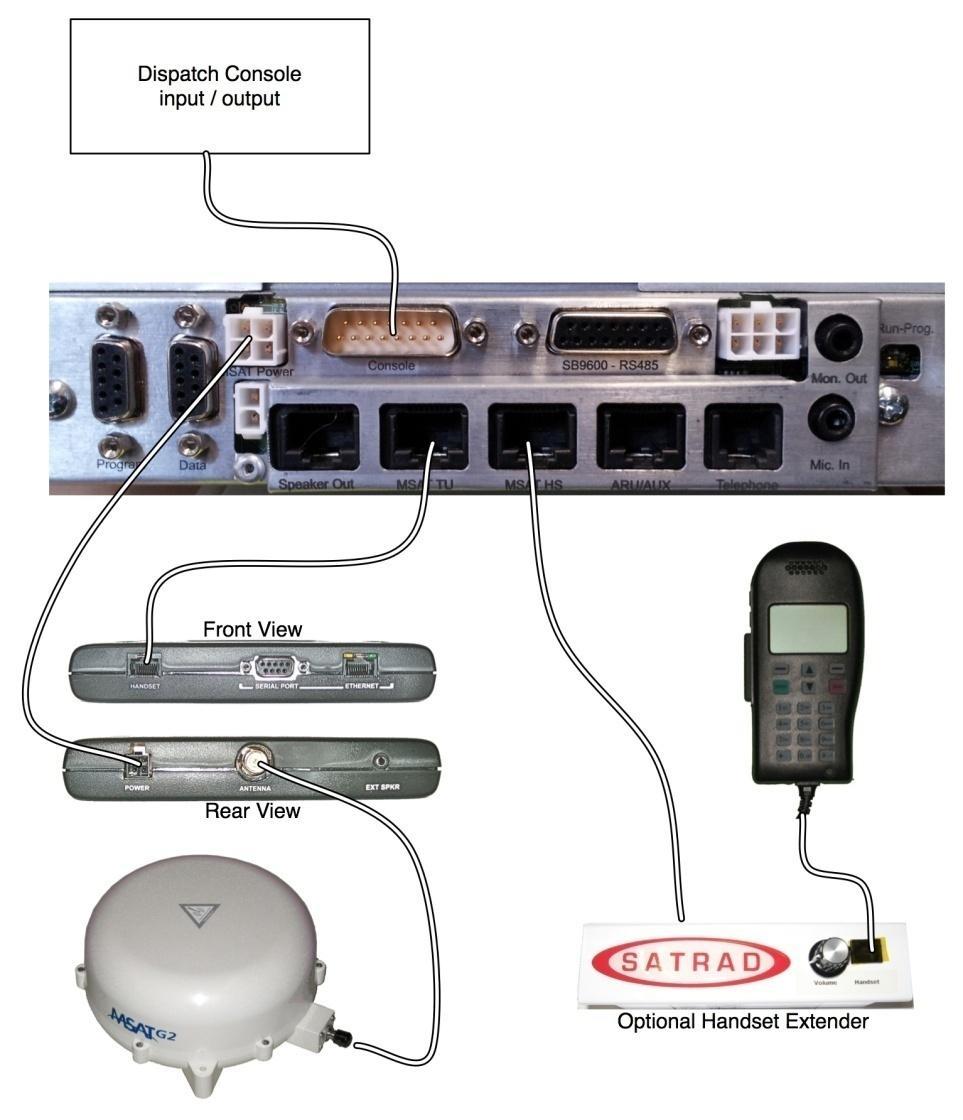
4 Typical Installation Wiring Diagram 4
5 Configuring the Network Bridge This section describes the different states of the DIP switches, and how they can be set for different integration situations. If the existing system operates using EIA tone signaling, then skip this section. Remove any yellow kapton tape covering the switch before toggling the switch. Refer to the connection tables for locations of signal input and outputs. 1. PTT (push to talk) - The COR signal coming from the existing system may either be normally high and switch to low when receiving a transmission, or it may be normally low and switch to high. The switch needs to be in the position that matches the output logic of the existing system. The switch that needs to be toggled depends on which port the signal will be applied to. a. PTT1 Console b. PTT2 AUX/ARU c. PTT3 SB9600 COR signal detected 1 0 COR output logic of existing equipment 2. COR (carrier operated relay) The control method of the network bridge, for when the MSAT-G2 is receiving a signal, needs to be configured to match the expected PTT input logic for the existing equipment. There are 3 basic states these switches can select. a. Pull up active high PTT signal generated b. Pull up active low 1 0 Active Low State Active High State Active Low State Active High State PTT output logic of the network bridge c. No pull up This is for when the existing equipment has a positive signal that can be re-directed to the COR input on the same device. The network bridge will control it like normally open switch and close the switch when there is a COR signal from the G2. Is this state the network bridge doesn t supply any signals and the HI-LO switches are disabled. 3. Auto power up The network bridge can be configured to automatically turn back on in case of a power outage. Once power is restored the device will re-boot. If this in not desired toggle the switch to the OFF position. The device will then need to be manually turned back on when power is restored. 5

6 Beam Coverage This section details the satellite service coverage of the SATRAD system. In order to make select good installation locations review the graphic showing the approximate coverage of each beam. Note that in the fringe (between the borders of 2 beams) there can be cross over problems. Select the beam that offers the strongest signal strength. The SATRAD-CIS system automatically selects the current beam when the unit is commissioned. If the need arises to change the beam manually the CIS first needs to be placed into transparent mode. Follow the next set of instructions to change the beam. 1. Press the PWR button on the side of the handset. 2. As soon as the tone is heard release the PWR button. 3. Press the MENU key. 4. Scroll to the ADMIN selection and press select. 5. Scroll to the X-OVER selection and press select. 6. Scroll to the desired beam, and press select. 7. The system will now ask to continue, press yes. 8. Allow to the CIS to return to normal mode. The user must not press any button for 60 seconds. The CIS will reboot the transceiver, and a 2 tone beep series will be heard. 6

7 Power up This section describes the recommended testing steps to ensure that the installation has been properly performed. It will be helpful to have a person with another SATRAD-G2 system to perform receiving and transmit test. 1) Check the antenna, and ensure that there are no obstructions (including people, animals, trees, or buildings). 2) Connect the handset to the MSAT-HS port in the back of the CIS. 3) Turn the power on by pressing the red button on the front of the CIS. The power LED should light up. 4) Observe the LED s on the front of the CIS they all should light briefly. 5) During normal operation the LED s will act in the following manner. a b c d e From left to right the indicators are as follows. a) SATRAD steady on means the systems is running. b) Voice status i. Off when the PTT / COR is inactive. ii. On when the PTT /COR is pressed (push to talk request received). iii. Flashes quickly when voice data is being transmitted over the satellite (PTT is active). iv. Flashes slowly when voice data is being received over the satellite system. c) Interface, flickers when data is being exchanged between the CIS and the SATRAD-G2. d) Satellite i. Steady on means the satellite link is established. ii. Flashing means the link is currently being created. iii. Steady off means the link is down. e) Power; on indicates power is turned on, off indicates the power is turned off. 7
8 Test the System This section gives instructions on how to test the SATRAD-CIS once installed to ensure it is properly functioning. It will be helpful at this time to have a second SATRAD-G2 available to help test. 1) Press the PTT on the SATRAD hand set while at the same time observing the b LED. The LED should turn on. 2) Press the PTT button in the SATRAD handset, and speak a short message (testing ), and at the same time observe the voice status LED b. The LED should turn on, then after a few seconds the LED should flash rapidly. The handset will display USER-ON. The message should be heard on the second SATRAD-G2. Release the PTT button. 3) Request a voice transmission from the second SATRAD-G2. Observe the voice status indicator b, the LED should flash slowly. Observe the handset it should display the DN number (device number, 4 digits long) of the second SATRAD-G2. The audio should be heard at the handset. 4) At the console, select the SATRAD resource, then initiate a transmission and speak a short message. Observe the following: a. The voice indicator b should illuminate then flash quickly. b. The SATRAD handset should display USER-ON. c. The person on the second SATRAD-G2 should hear the message. 5) Request the person on the second SATRAD-G2 to transmit a voice message. Observe the following: a. The voice status indicator b should flash slowly. b. The SATRAD resource icon on the console should illuminate (where supported). c. The message is heard at the console. 8
 Description Position Characteristics Ground 1 via 470 Ohm, 0.")
9 Connections This section describes the signal outputs of the network bridge. This is intended to help determine how to connect the network bridge to the existing communication system. 1. Console Port (15 position d-sub male connector) Description Position Characteristics Ground 1 via 470 Ohm, 0.47uf Analogue Differential Input A +ve 2 Analogue Differential Input A -ve 3 Analogue Differential Input B +ve 4 Analogue Differential Input B -ve 5 ARU Audio Output + (to Console) 6 PTT / COR Ground Reference 7 ARU Audio Input + (from Console) 8 Digital Ground 9 Data Port Console Transmit 10 RS232 Output Balanced Line Output 600 Ohms Impedance Balanced Line Input 600 Ohms Impedance Data Port Console Receive 11 RS232 Input Carrier Operated Relay (1) - Output 12 Open Collector Output, active low, NI-3005 has a 4.7k ohm pull-up to 5 volts Push to Talk Input A 13 Open Collector Input, active low, NI has a 4.7k ohm pull-up to 5 volts ARU Audio Output - (to Console) 14 Balanced Line Output 600 Ohms Impedance ARU Audio Input - (from Console) 15 Balanced Line Input 600 Ohms Impedance 9
 5 600 Ohm Balanced Line Auxiliary Audio Input (+) 6 600 Ohm Balanced Line Auxiliary Audio Input (-) 7 600 Ohm Balanced Line 13.")
10 2. SB9600-RS485 port (can be used as P25 connection) Description Position Characteristics Chassis Ground 1 RS-485 Bus (+) 2 RS-485 Bus (-) 3 Auxiliary Audio Output Ohm Balanced Line Auxiliary Audio Output (-) Ohm Balanced Line Auxiliary Audio Input (+) Ohm Balanced Line Auxiliary Audio Input (-) Ohm Balanced Line 13.5 Volts MSAT 8 Digital Ground 9 RS-485 Busy 10 No Connection 11 COR (1) Output 12 PTT (1) Input 13 PTT (3) Input 14 Digital Ground 15 10

11 3. Data - 9pos d-sub female This connection sends data out of the network bridge when performing diagnostics or during programming. Description DB-9 Pin Characteristics Data Carrier Detect - Output 1 DCD RS-232 Transmit Data - Output 2 Tx - RS-232 Receive Data - Input 3 Rx - RS-232 Data Terminal Ready - Input 4 DTR - RS-232 Ground 5 Ground Data Set Ready - Output 6 DSR - RS-232 Request to Send - Input 7 RTS RS-232 Clear to Send - Output 8 CTS RS-232 Ring Indicator - Output 9 RI RS Program 9 pos d-sub female This port is only for when the device is being programmed or under diagnostics and is connected to the separate computer. Description DB-9 Pin Characteristics 1 Receice Data - Input 2 Rx - RS-232 Transmit Data - Output 3 Tx - RS-232 Microprocessor Reset 4 Digital Ground 5 Ground Microprocessor Status - 6 Output Request to Send - Input 7 Jumpered to DB 9 - Pin 8 Clear to Send - Output 8 Jumpered to DB 9 - Pin
 4 Output from NI-3005 ARU Audio Output B (-) 5 Output from NI-3005 Signal Ground 6 Signal ground ARU Link Up COR (3) 7 Output from NI-3005 ARU PTT (2) 8 Input to NI-3005 600 Ohm")
12 5. AUX/ARU port RJ45 ARU RJ-45 Jack Position Direction Characteristics ARU Audio Input B (+) 1 Input to NI-3005 ARU Audio Input B (-) 2 Input to NI-3005 ARU Link Up COR (2) 3 Output from NI-3005 ARU Audio Output B (+) 4 Output from NI-3005 ARU Audio Output B (-) 5 Output from NI-3005 Signal Ground 6 Signal ground ARU Link Up COR (3) 7 Output from NI-3005 ARU PTT (2) 8 Input to NI Ohm Balanced Line 600 Ohm Balanced Line 600 Ohm Balanced Line 600 Ohm Balanced Line 6. Speaker out RJ45 Speaker RJ-45 Jack Position Direction Characteristics Speaker Out (-) 1 Output from NI-3005 expects 8 Ω load Speaker Out (-) 2 Output from NI-3005 expects 8 Ω load Digital Ground 3 Level Control 4 Input from NI V DC 5 Output from NI-3005 Digital Ground 6 Speaker Out (+) 7 Output from NI-3005 expects 8 Ω load Speaker Out (+) 8 Output from NI-3005 expects 8 Ω load 12
 Tip 4 Positive (Pair 1) 5 Pair 2 Ground 6 Pair 3 8. Mic in 3.")

13 7. Telephone RJ11 This port is used for connecting a telephone to the system. The device emulates a PSTN central office, including; supervisory voltages, ring tone, busy tone, and dial tone. Decription Position Characteristics + 5 Volts DC 1 Pair 3 2 Pair 2 Ring 3 Negative (Pair 1) Tip 4 Positive (Pair 1) 5 Pair 2 Ground 6 Pair 3 8. Mic in 3.5mm jack This connector is used for the microphone on hands free calling with thesatrad-g2 in telephone mode. Sleeve: Ground Tip: 600 ohm balanced input Ring: 600 ohm balanced input 9. Mon out 3.5mm jack The output is 1.2V rms and is for use as an input to the console audio port. Tip Ring Sleeve Sleeve: Ground Tip: 8 ohm output unbalanced isolated audio ouput. Ring: Line level output unbalanced audio, un-used in power amplifier mode. 10. Relay If it is desired to control separate devices with the network bridge this connector may be used. Examples: public address, horn, or lights. Molex Connector 6 Pin Pin # Relay A Normally Open 1 Relay A Normally Closed 2 Relay A Common 3 Relay B Normally Open 4 Relay B Normally Closed 5 Relay B Common 6 Relay
14 Sequential Paging Formats Two-Tone Paging - Quick Call 2 is one of the many paging formats collectively known as Two-Tone paging. For most pages, the encoders produce two individual audio tones with specific timing, in sequence. The pagers receive the tones and examine them. If the transmitted tones and timing match what the pager was programmed for, the pager will activate. Individual / Group Paging - Motorola Quick Call 2 paging codes are transmitted at a 1 second, 3 second timing with no silence gap between the tones. The timing is referred to as 1/3 and is pronounced, "one second, three second" not "one divided by three". 1/3 timing is normally employed to activate individual pagers or groups of pagers. All-Call - QC2 also has a provision to activate an entire fleet of individual or group pagers with one signal. This is the All-Call page. An All-Call page is a continuous tone, which lasts for 8 seconds. Pagers, which have the All-Call tone as part of their individual or group tone, will normally activate with this All-Call signal as well. Pressing the same code button twice on the encoder normally activates all-call paging. For example, if you enter the code 61 from code group 4, the encoder knows you want to send a 1 second / 3 second page with the tones Hz & Hz. However if you enter the code 66 from code group 4, the encoder will send an 8 second All-Call page of Hz. Stacked Paging - Many paging encoders and most law enforcement and fire department communications consoles, have the ability to transmit an entire group of pages with the press of one button. Each page is transmitted with a small silence gap (usually one second) inserted between each page so the pagers can determine the end of a page, then analyze if that last page was for them. Activate other devices - Paging technology is also incorporated into other control devices. These are usually referred to as receivers/decoders/controllers also known as "RDC". The RXC-2000 is an RDC. The first two functions of receiving and decoding are exactly what a pager does, however the controller function is what really sets them apart. An RDC has various output relays and audio, in addition to local activation controls which can be programmed to perform various actions when it picks up the correct paging code. Whereas a pager can only beep and give a voice message, an RDC can take that same pager signal and begin an entirely new process of controlling equipment and process from the same page. A common function for an RDC is to activate a fire siren when a fire call is dispatched. Using internal timers and output relays, the RDC can engage the siren for a predetermined time, and then automatically turn it off. RDC's can also open overhead doors, turn on pumps, light up rooms or equipment bays and engage PA systems to deliver audio messages. All this is done transparently using the same signal sent to the pagers. Tone lengths Standard ZVEI1 EIA CCIRI EEA CCITT EURO Tone Duration (ms) Pause Duration (ms)
15 Tone Frequency Values Standard Repeat Alarm Free tone Group tone ZVEI ZVEI DZVEI ZVEI GB ZVEI F ZVEI DP EIA CCIR CCIRI EEA CCITT EURO VDEW Motorola Gold Elite Audio Level There are five different types of signals that can be transmitted from the BIM (Base Interface Module) including Tone Remote Control, Voice, Paging Tones, Alert Tones and Test Tones. A single transmit level POT on the BIM adjust all of these signals together. The relative levels of these five types of signals are fixed according to the description below: 1. TONE REMOTE CONTROL The relative amplitude of High Guard, Function Tone, and Low Guard are defined according to the Tone Remote Control Standards such that Functional Tone is 10 db below High Guard and Low Guard is 30 db below High Guard. 2. VOICE A 1000 Hz tone injected into the microphone path above the DLM (Digital Line Memory) threshold should be near the level of High Guard. With the dynamic of the DLM circuit, overage voice will be 6 to 10 db below the level of this tone. 3. PAGING TONES Paging Tones are de-emphasized with a pole at 300 Hz to compensate for the pre-emphasis at the base station. As a result paging tones are transmitted flat. The relative amplitude of the paging tones is adjusted to be slightly higher than average voice for 1000 Hz tones. Lower frequency tones may be as much as 9 db higher than overage voice and high frequency tones may be as much as 9 db lower according to the de-emphasis curve. This assures maximum signalling sensitivity without the risk of distortion and false signalling due to IDC clipping. 4. ALERT TONES The primary purpose intended for alert tones is to provide means for altering field units under certain conditions. The amplitude of this tone received by the field unit should be loud enough to demand attention but not so loud as to be painful. This is also the level of 1000 Hz paging tones. NOTE: If a paging exist on a particular channel, the Alert Tones should not be set higher than 0 db to avoid clipping of low frequency paging tones in the BIM line driver. 5. TEST TONES As on aid to setting transmit level, a BIM will generate a sequence of tones after its reset button is depressed and released. This sequence of tones consists of 5 seconds of 1000 Hz followed by 3 seconds of 300 Hz followed by 3 seconds of 3000 Hz. The amplitude of these tones will be the same as Alert Tones and 1000 Hz Paging Tones. All three test tones are transmitted at the same level and provide a simple means of checking frequency response of the signal path to the base station. Since Guard Tone is not present during the test tone sequence, the transmitter will not key. 15
16 There attached chart provides a graphical representation of the relative signal levels for a typical example where the Test Tone is set for 0 dbm. In this case 300 Hz paging tones would be +9 dbm and 3000 Hz paging tones would be 9 dbm. Adjusting the BIM transmit pot will move all these signals up or down together. Industry Standard Levels Guard and Function Tone Waveform High level guard tone 0db Audio, or paging, or MDC signaling Low level guard tone Function tone -10db 16
17 Function key tones: Mon.: 2050 H z F1: 1950 H z F2: 1850 H z F3: 1750 H z F4: 1650 H z F5: 1550 H z F6: 1450 H z F7: 1350 H z F8: 1250 H z F9: 1150 H z F10: 1050 H z F11: 950 H z F12: 850 H z F13: 750 H z F14: 650 H z F15: 550 H z Trouble Shooting Tips 1. Review the wiring for proper interconnection. 2. Check the RUN / PROG switch and ensure that it is in the RUN position. 3. Ensure the power has been turned on. If the system doesn t reboot after a power failure open the CIS and locate the auto POWER-UP switch beside the fan and toggle to the on position. 4. Check for proper beam selection. If the signal strength is below 70 then the wrong beam may be selected. For any further questions contact technical support. a. Web: b. Toll Free: c. Phone:
18 Notes 18
Installation Manual Mobile Integration System
 Installation Manual Mobile Integration System Table of Contents Kit Contents... 2 Overview... 3 Installation Instructions... 6 Power up... 12 Test the System... 13 Beam Coverage... 14 Trouble Shooting
LBI-31564A. Mobile Communications. DELTA - SX MHz RADIO COMBINATIONS (NEGATIVE GROUND ONLY) Maintenance Manual
 Maintenance Manual") A Mobile Communications DELTA - SX 136-174 MHz RADIO COMBINATIONS (NEGATIVE GROUND ONLY) Maintenance Manual TABLE OF CONTENTS MILITARY AND SYSTEM SPECIFICATIONS................................. 2-3 COMBINATION
A Mobile Communications DELTA - SX 136-174 MHz RADIO COMBINATIONS (NEGATIVE GROUND ONLY) Maintenance Manual TABLE OF CONTENTS MILITARY AND SYSTEM SPECIFICATIONS................................. 2-3 COMBINATION
RMV25 / RMV50 RMU25 / RMU45
 RMV25 / RMV50 RMU25 / RMU45 Owner's Manual TABLE OF CONTENTS INTRODUCTION... 3 FCC Requirements... 3 SAFETY WARNING INFORMATION... 3 CONTROLS and INDICATORS... 5 FRONT PANEL... 5 LCD Icons and Indicators...
GETTING STARTED. Radio layout. LCD display with icons
 GETTING STARTED Radio layout LCD display with icons 1. Key lock button 2. Battery meter 3. Main channel indicator 4. Scan icon 5. Roger beep indicator 6. CTCSS sub-channel indicator 7. VOX indicator 1
Contents 1. FEATURES EQUIPMENT DESCRIPTION INSTALLATION OPERATION TROUBLESHOOTING SPECIFICATIONS...
 Contents 1. FEATURES... 3 2. EQUIPMENT DESCRIPTION... 3 3. INSTALLATION... 5 4. OPERATION... 5 5. TROUBLESHOOTING... 7 6. SPECIFICATIONS... 8 2 1. FEATURES Telephone Foreign Exchange Subscriber (FXS) Service:
EDACS WALL MOUNT STATION. Maintenance Manual. Mobile Communications LBI-31838A TABLE OF CONTENTS
 A Mobile Communications EDACS WALL MOUNT STATION TABLE OF CONTENTS SYSTEM BOARD & REGULATOR BOARD.......... LBI-31892 KEY/DISPLAY BOARD MAINTENANCE MANUAL.... LBI-31940 Maintenance Manual Printed in U.S.A.
MobileRadio. Owner'sManual
 EMH MobileRadio Owner'sManual TABLE OF CONTENTS Introduction... 1 Basic Operation... 2 Code Guard Operation... 3 EMH Radio Controls... 4 Button Functions... 4 Built-in Features... 7 Keypad Microphone Operation...
PR-1. Paging Tone Regenerator. Manual Revision: Covers Software Revisions: PR-1: 1.1 and higher. Covers Hardware Revisions: PR-1: 283B
 PR-1 Paging Tone Regenerator Manual Revision: 2008-01-14 Covers Software Revisions: PR-1: 1.1 and higher Covers Hardware Revisions: PR-1: 283B 1 SPECIFICATIONS Operating Voltage Operating Current Operating
SNV-12 Voter Quick Reference Help Sheets
 Chassis, Power Supply, and CIM Module SNV-12 Configuration Settings and Adjustments (0=Off, 1=On) Chassis Rear Panel: Designator Factory Setting Switch Choices AC Line Voltage Rear Panel AC Input Module
TM-800 Main Station. Instruction Manual. TELIKOU Systems All Rights Reserved
 Intercom System TM-800 Main Station Instruction Manual TELIKOU Systems All Rights Reserved I. Introduction Thank you for choosing TELIKOU intercom product. TM-800 main station is suitable for television
CONNECT SYSTEMS INCORPORATED 5321 Derry Ave., Suite B Agoura Hills, CA FLEX SERIES UNIVERSAL CONTROLLER
 CONNECT SYSTEMS INCORPORATED 5321 Derry Ave., Suite B Agoura Hills, CA 91301 Phone (805) 642-7184 Fax (805) 642-7271 FLEX SERIES UNIVERSAL CONTROLLER FLEX IIIA CTCSS COMMUNITY TONE PANEL User s Instruction
Technical Equipment Specification
 STATE OF CALIFORNIA Office of the State Chief Information Officer Public Safety Communications Division Technical Equipment Specification Equipment Type: Transmitter/Receiver Mobile Relay/Base/Control
SR3400 Base Station Module Configuration and Use Series-2 Cards Only
 SR3400 Base Station Module Configuration and Use Series-2 Cards Only A.W. Communication Systems Ltd Crook Barn, The Crook Rowel Town, Carlisle Cumbria Telephone (44) 1697-748777 Fax (44) 1697-748778 www.toneremote.com
Cross-Connect Interface
 Cross-Connect Interface User Manual Document #: 050-015-0036R01 November 2006 TASC Systems Inc. Langley, BC Canada Cross-Connect System User Manual Preface This document describes the installation, commissioning
Basic Transceiver tests with the 8800S
 The most important thing we build is trust ADVANCED ELECTRONIC SOLUTIONS AVIATION SERVICES COMMUNICATIONS AND CONNECTIVITY MISSION SYSTEMS Basic Transceiver tests with the 8800S Basic Interconnects Interconnect
MASTR II AUXILIARY RECEIVER 19D417546G7 & G8 & ANTENNA MATCHING UNITS 19C321150G1-G2. Maintenance Manual LBI-30766L. Mobile Communications
 L Mobile Communications MASTR II AUXILIARY RECEIVER 19D417546G7 & G8 & ANTENNA MATCHING UNITS 19C321150G1-G2 Printed in U.S.A Maintenance Manual TABLE OF CONTENTS Page SPECIFICATIONS.....................................................
CONNECT SYSTEMS INCORPORATED 1802 Eastman Ave., Suite 116 Ventura, Ca FLEX SERIES II UNIVERSAL CONTROLLER
 CONNECT SYSTEMS INCORPORATED 1802 Eastman Ave., Suite 116 Ventura, Ca. 93003 Phone (805) 642-7184 Fax (805) 642-7271 FLEX SERIES II UNIVERSAL CONTROLLER MULTIMODE INTERCONNECT AND EIA TONE REMOTE E&M VERSION
BTD-2. BTD-2 MOD-1272 Addendum
 BTD-2 Burst Tone Decoder BTD-2 MOD-1272 Addendum Motorola MDC-1200 ANI Mute Option Manual Revision: 2008-07-21 Covers Software Revisions: BTD-2: 1.0 & Higher Covers Hardware Revisions: UED-1: 283B 1 SPECIFICATIONS
PLUG N PLAY WATT DIGITAL FM TRANSMITTER. April, 2002 IM No
 PLUG N PLAY 1000 1000 WATT DIGITAL FM TRANSMITTER April, 2002 IM No. 597 9972 OPERATION/FEATURE PROGRAMMING. The PNP 1000 allows the user to select many types of different operating parameters and features.
Microphone audio, from the MFJ-1278B to your transmitter. Ground, audio and PTT common. Push-to-talk, to allow the MFJ-1278B to key your transmitter.
 Computer interfacing, covered in the previous chapter, is only half the interfacing task. The other half is connecting your MFJ-1278B to your radios. MFJ-1278B Radio Ports Interfacing the MFJ-1278B to
Mastr III P25 Base Station Transmitter Tune-up Procedure
 Mastr III P25 Base Station Transmitter Tune-up Procedure 1. Overview The Mastr III Base Station transmitter alignment is performed in several steps. First, the Transmit Synthesizer module is aligned to
TACT TA-4800 RACK MOUNT VERSION USER HANDBOOK. Issue 2, Dec, 2009 ACMA SUPPLIER S CODE N468 NEW ZEALAND TELEPERMIT PTC 210/96/003
 TACT TA-4800 MAN ALONE PERSONAL SAFETY ALARM RADIO / TELEPHONE INTERCONNECT RACK MOUNT VERSION USER HANDBOOK Issue 2, Dec, 2009 ACMA SUPPLIER S CODE N468 NEW ZEALAND TELEPERMIT PTC 210/96/003 DESIGNED
CONNECT SYSTEMS INCORPORATED 1802 Eastman Ave., Suite 116 Ventura, Ca FLEX III UNIVERSAL CONTROLLER
 CONNECT SYSTEMS INCORPORATED 1802 Eastman Ave., Suite 116 Ventura, Ca. 93003 Phone (805) 642-7184 Fax (805) 642-7271 FLEX III UNIVERSAL CONTROLLER INTERCONNECT DISPACH SYSTEM AA User s Instruction Manual
B & D Enterprises 1P repeater controller pg 1 INTRODUCTION:
 B & D Enterprises 1P repeater controller pg 1 INTRODUCTION: The 1P is a basic repeater controller. The controller uses low power devices and stores all commands and system status in non-volatile EE prom.
HF-SSB MICOM - LINK - FDN6123 HF-SSB MICOM - LINK
 American Communication Systems Discover the Power of Communications TO ORDER VISIT http://www.ameradio.com HF-SSB MICOM - LINK - FDN6123 HF-SSB MICOM - LINK Instruction Manual 6886857J01 Table of Contents
AMERITRON RCS-12 AUTOMATIC ANTENNA SWITCH
 AMERITRON RCS-12 AUTOMATIC ANTENNA SWITCH INSTRUCTION MANUAL PLEASE READ THIS MANUAL BEFORE OPERATING THIS EQUIPMENT! 116 Willow Road Starkville, MS 39759 USA 662-323-8211 Version 3B Printed in U.S.A.
20-27B. Tone Panel. Version 1.10
 20-27B Tone Panel Version 1.10 Printings Version 1.00: 1/16/01 Version 1.10: 10/11/02 TABLE OF CONTENTS SPECIFICATIONS... 1 1.0 GENERAL DESCRIPTION... 2 1.1 Description... 2 1.2 Capabilities and Features...
Programming Parameter Guide
 Secure Wireless Microphone ELITE PRO Programming Parameter Guide rev:1 How to use Programmer: Start Programming application Runs On PC or Mac running Windows 7/10. To put Handset into programming mode,
Maintenance Manual ERICSSONZ LBI-31552E
 E Maintenance Manual TONE REMOTE CONTROL BOARD 19A704686P4 (1-Frequency Transmit Receive with Channel Guard) 19A704686P6 (4-Frequency Transmit Receive with Channel Guard) ERICSSONZ Ericsson Inc. Private
This is by far the most ideal method, but poses some logistical problems:
 NXU to Help Migrate to New Radio System Purpose This Application Note will describe a method at which NXU Network extension Units can aid in the migration from a legacy radio system to a new, or different
Model: TP380 User Manual
 Model: TP380 User Manual 1 UHF RADIO TRANSCEIVER MODEL: TP380 USER MANUAL INTRODUCTION Thank you for selecting the Oregon Scientific TP380 as your product of choice. This product is a portable, easy-to-use
Specification Sheet. MC SERIES Deskset Controllers
 Specification Sheet MC SERIES Deskset Controllers Pictured from left to right are the MC2000 Advanced Model which includes Tone Paging and MDC-1200 signaling, the MC2500 Multi-channel Model, and the MC1000
Pacific Antenna Simple Keyer Kit
 Pacific Antenna Simple Keyer Kit Specifications and Features: Speed range of 5 to 30 wpm Operates in either iambic A or B mode, with B being the default 2 message memories Tune and Beacon modes Built on
DX AM FM SSB CW PA Amateur Base Station Transceiver OWNER S MANUAL RX / TX 2 4 POWER NF CHANNEL MODE RF POWER OFF CAL OFF OFF CALIBRATE
 1 2 3 6 4050 ULA 6070 TI 80 90 100 9 DX 2517 2517 RX / TX 0 2 4 SWR WATTS SET 81012 22 1 010 3 2030 5 MOD 7 ON dbover 9 SIGNAL +20 +40+60 PA FM AM USB LSB CW POWER ON SWR NB / ANL R.BEEP +10KHz NF CHANNEL
ICS REPEATER CONTROLLERS
 ICS REPEATER CONTROLLERS SINGLE M USER MANUAL INTEGRATED CONTROL SYSTEMS 1613 Bonnie Avenue Dixon, IL 61021 Voice 815-284-6963 Fax 815-288-0718 Website www.ics-ctrl.com Last updated 01/08/2005 Single M
DPT-1 & DPT-2. Dial Access Paging Terminal. Manual Revision: Covers Firmware Revisions: DPT: 1.57 and higher
 DPT-1 & DPT-2 Dial Access Paging Terminal Manual Revision: 2008-07-22 Covers Firmware Revisions: DPT: 1.57 and higher Covers Hardware Revisions: DPT-1: E and higher DPT-2: F and higher 1 TABLE OF CONTENTS
TX4400 UHF CB RADIO INSTRUCTION MANUAL TX4400 INSTRUCTION MANUAL PAGE 1
 TX4400 UHF CB RADIO INSTRUCTION MANUAL TX4400 INSTRUCTION MANUAL PAGE 1 TABLE OF CONTENTS GENERAL................................... 3 FEATURES.................................. 3 BASIC OPERATION...4 Front
Application Note: Testing P25 Conventional Radios Using the Freedom Communications System Analyzers
 : Testing P25 Conventional Radios Using the Freedom Communications System Analyzers FCT-1007A Motorola CPS and Tuner Software Motorola provides a CD containing software programming facilities for the radio
Testing Motorola P25 Conventional Radios Using the R8000 Communications System Analyzer
 Testing Motorola P25 Conventional Radios Using the R8000 Communications System Analyzer Page 1 of 24 Motorola CPS and Tuner Software Motorola provides a CD containing software programming facilities for
TECHNICAL NOTES MT-3/4 Radio Systems TN855 CI-DSP-223 Telex (Vega) DSP Tone-Remote Adapter
 DSP Tone-Remote Adapter") The Telex DSP-223 tone-remote adapter provides a reliable means of remotely controlling Codan base stations and repeaters. The adapters can be used in conjunction with tone-remote control consoles which
The Telex DSP-223 tone-remote adapter provides a reliable means of remotely controlling Codan base stations and repeaters. The adapters can be used in conjunction with tone-remote control consoles which
MODEL NC221 MOBILE TWO-TONE SEQUENTIAL DECODER INSTRUCTION MANUAL
 15385 Carrie Drive Grass Valley, CA 95949 Office: (530) 477-8400 Tech. Support: (530) 477-8402 FAX: (530) 477-8403 Sales: (800) 874-8663 Email: tech@norcommcorp.com Web:www.norcommcorp.com MODEL NC221
Programming. Advanced Features
 Programming 4 Advanced Features Some of the MaxTrac models have the ability to be programmed for advanced features. These features include Channel Scan, Handset Muting, Expanded Accessory Connector, MDC-1200,
Technical Application Note #3
 CRC CACTUS Radio Club, Inc. This Technical Application Note describes alignment procedure for a Palomar Telecom RBC- 700 series controller. The following instructions are individually described: Initial
T25-35SA Subaudible Tone Decoder
 T25-35SA Subaudible Tone Decoder The Mueller Broadcast Design T25-35SA subaudible tone decoder provides a simple and reliable way to detect the 25 and 35 Hz control tones sent by many satellite-delivered
ICS REPEATER CONTROLLERS
 ICS REPEATER CONTROLLERS BASIC CONTROLLER USER MANUAL INTEGRATED CONTROL SYSTEMS 1076 North Juniper St. Coquille, OR 97423 Email support@ics-ctrl.com Website www.ics-ctrl.com Last updated 5/07/15 Basic
Programming Parameters - Feature Comparison : Rev 1
 Secure Wireless Microphone ELITE PRO CLASSIC Programming Parameters - Feature Comparison : Rev 1 How to use Programmer: Start Programming application Runs On PC or Mac running Windows 7/8. To put Handset
INDEX...2 INTRODUCTION...3 IMPORTANT NOTES...3 INSTALLING THE SOFTWARE...3 ST-965 PROGRAMMING SOFTWARE...6
 ST-965 VX/D SMARTRUNK II & SMARTRUNK XPRESS Logic board Programming Software 2.9e User s Guide Revision R2.9 10/10/2008 INDEX INDEX...2 INTRODUCTION...3 IMPORTANT NOTES...3 INSTALLING THE SOFTWARE...3
Use of Voter Comparators to Improve Railroad Radio Communications
 Use of Voter Comparators to Improve Railroad Radio Communications Purpose This Application Note will describe the use of the SNV-12 Voter Comparator to expand radio coverage in railroad applications. Introduction
Interface: Serial EIA RS-232D/CCITT V.24, DCE; RTS/CTS delay 0,8 or 64 ms (user-selectable).
.") BLACK BOX PWR RTS TD-1 RD-1 TD-2 DCD RD-2 TEST DIG ANA REM LDM-MR 19.2 REM ANA DIG AGC 2/4 WIRE ABLE / ABLE SWITCHES 2 W 4 W 1 2 3 4 CARRIER LEVEL 0 dbm -3 dbm -6 dbm -9 dbm PIN 21 (RLB) RPF PIN 18 AN.
BLACK BOX PWR RTS TD-1 RD-1 TD-2 DCD RD-2 TEST DIG ANA REM LDM-MR 19.2 REM ANA DIG AGC 2/4 WIRE ABLE / ABLE SWITCHES 2 W 4 W 1 2 3 4 CARRIER LEVEL 0 dbm -3 dbm -6 dbm -9 dbm PIN 21 (RLB) RPF PIN 18 AN.
LBI-31807D. Mobile Communications MASTR II REPEATER CONTROL PANEL 19B234871P1. Maintenance Manual. Printed in U.S.A.
 D Mobile Communications MASTR II REPEATER CONTROL PANEL 19B234871P1 Maintenance Manual Printed in U.S.A. This page intentionally left blank 13 PARTS LIST 12 PARTS LIST LBI-31807 11 PARTS LIST 10 SCHEMATIC
LBI Installation & Operation
 Installation & Operation EDACS Power Monitor Unit ericssonz CONTENTS TABLE OF CONTENTS Page INTRODUCTION... 6 DESCRIPTION... 6 APPLICATION NOTES... 7 VAX SITE CONTROLLER COMPUTER... 7 APPLICATION SOFTWARE
Interfacing to the SoundStation VTX 1000 TM with Vortex Devices
 Interfacing to the SoundStation VTX 1000 TM with Vortex Devices Application Note Polycom Installed Voice Business Group September 2004 Rev. F TABLE OF CONTENTS TABLE OF CONTENTS... 2 INTRODUCTION... 6
Owner s Manual. Model G-223. GMRS/FRS Radio. FEATURES 22 Channels Scan 22 Key Pad Lock Call Alert Power HI/LO Roger Beep Tone
 Owner s Manual Model G-223 GMRS/FRS Radio FEATURES 22 Channels Scan 22 Key Pad Lock Call Alert Power HI/LO Roger Beep Tone This device complies with Part 15 of the FCC rules. Operation is subject to the
BandMaster V Manual. Installation
 BandMaster V Manual Installation Installing and configuring the BM-5 BandMaster V is a simple process. All the configuration process is done from the front panel. Installation and configuration steps are
Lynx. RoIP Gateway DISPATCH LYNX MOBILE. Optional serial ports provide remote control of radio configuration over the VoIP network.
 LYNX MOBILE Lynx DISPATCH RoIP TM SYSTEM Gateway LYNX TM ROIP GATEWAY OVERVIEW The Lynx system provides Radio over IP (RoIP) communications interoperability between radio base stations and VoIP networked
MAINTENANCE MANUAL FOR CONVENTIONAL NETWORK INTERFACE
 C MAINTENANCE MANUAL FOR CONVENTIONAL NETWORK INTERFACE TABLE OF CONTENTS Page SPECIFICATIONS................................................ 1 INTRODUCTION.................................................
PC Tune PC Tune Test Procedures for 5100 Series Portable Radios
 PC Tune PC Tune Test Procedures for 5100 Series Portable Radios Part Number 002-9998-6513014 August 2008 Copyright 2006, 2007, 2008 by EFJohnson Technologies The EFJohnson Technologies logo, PC Configure,
Easy-Link Plus Version 2.2
 Easy-Link Plus Easy-Link Plus Version 2.2 Copyright 1994-2000 IDA Corporation All Rights Reserved This device complies with Part 15 of the FCC Rules. Operation is subject to the following two conditions:
5570M Series Intercom Installation and Operation Guide
 5570M Series Intercom Installation and Operation Guide Isolated balanced/unbalanced lines Audio signals for the 5570M are transmitted over a wire pair using balanced line technology. An isolation transformer,
Copyright 1996 Codan Pty Ltd.
 No part of this handbook may be reproduced, transcribed, translated into any language or transmitted in any form whatsoever without the prior written consent of Codan Pty Ltd. Copyright 1996 Codan Pty
MAINTENANCE MANUAL AUDIO AMPLIFIER BOARD 19D904025G1 (MDR) AUDIO AMPLIFIER BOARD 19D904025G2 (MDX)
 AUDIO AMPLIFIER BOARD 19D904025G2 (MDX)") A MAINTENANCE MANUAL AUDIO AMPLIFIER BOARD 19D904025G1 (MDR) AUDIO AMPLIFIER BOARD 19D904025G2 (MDX) TABLE OF CONTENTS DESCRIPTION............................................... Page Front Cover CIRCUIT
A MAINTENANCE MANUAL AUDIO AMPLIFIER BOARD 19D904025G1 (MDR) AUDIO AMPLIFIER BOARD 19D904025G2 (MDX) TABLE OF CONTENTS DESCRIPTION............................................... Page Front Cover CIRCUIT
CAT-260 Repeater Controller Computer Automation Technology, Inc
 CAT-260 Repeater Controller Computer Automation Technology, Inc 7378 W. Atlantic Blvd. #239 Margate, Florida 33063 Phone: (954) 978-6171 Fax: (561) 465-5891 Internet: http://www.catauto.com Table of Contents
JEM Radio II Operation Guide. Manual P/N M Victor Place Colorado Springs, Colorado
 JEM Radio II Manual P/N M09999-999 2115 Victor Place Colorado Springs, Colorado 80915 800.284.0399 www.jemcom.com Table of Contents Display... 3 Channel Entry... 4 Shortcuts... 4 Text Messages... 4 Buttons...
INSTALLATION AND OPERATION GUIDE
 VHF Marine Radio RT-311 INSTALLATION AND OPERATION GUIDE Navicom plaisance: Z.A. des Boutries, 78700 Conflans Ste Honorine Tel: 01.39.72.19.90 Fax: 01.39.19.28.98 Navicom Pro: 3, rue J. Cugnot, Z.A.C Petit
TRA TELEPHONE TO RADIO ADAPTER INSTRUCTION MANUAL. Manual Revision: Software Version: 4.2 & Higher
 TRA TELEPHONE TO RADIO ADAPTER INSTRUCTION MANUAL Manual Revision: 2006-10-31 Software Version: 4.2 & Higher 1 General Operating Voltage Standby Current Off-hook Current Ringing Current 1. SPECIFICATIONS
SECTION III OPERATION
 SECTION III OPERATION 3.1 INTRODUCTION This section contains information concerning the operation procedures for the BK Radio GPH Flex Mode Series handheld VHF radios. Information on installation and programming
OWNER S MANUAL FM HANDHELD TRANSCEIVER
 , OWNER S MANUAL RPU4200A FM HANDHELD TRANSCEIVER NOTE, OWNER S MANUAL RPU4200A FM HANDHELD TRANSCEIVER We are very grateful for your purchasing brand twoway radios produced by Relm Wireless Corporation.
ANI-F-KW1. Multi-Format ANI Encoder For Kenwood Radios. Manual Revision: Covers Software Revisions: ANI-F: 1.
 ANI-F-KW1 Multi-Format ANI Encoder For Kenwood Radios Manual Revision: 2009-02-04 Covers Software Revisions: ANI-F: 1.2 and higher This manual & product supports the following radios: Portable: TK-2180/3180
BFoxCon Manual. Version 0.2 October 30, 2017
 Overview The Byonics BFoxCon is a radio controller board designed to pair with a Baofeng UV-5R to create a transceiver for hidden transmitter hunts, also called T-hunts, foxhunts, and ARDF. It mounts on
MX800 BASE STATION SPECIFICATIONS
 MX800 BASE STATION SPECIFICATIONS Minimum performance to exceed the following for 30MHz to 960MHz*: Conforms but not all bands approved. GENERAL Frequency Range: AS4295-1995, R&TTE EC Directive 1995/05/EC,
Pair of PMR446 Two-Way Personal Radios Model: TP391
 Pair of PMR446 Two-Way Personal Radios Model: TP391 USER MANUAL MANUALE D USO MANUEL DE L UTILISATEUR BEDIENUNGSANLEITUNG MANUAL DE USUARIO MANUAL DO USUÁRIO HANDLEIDING BRUKSANVISNING P/N:086L004722-016
ACCESS CONTROL CENTER RADIO ACCESS SYSTEM INTERCONNECTION
 ACCESS CONTROL CENTER RADIO ACCESS SYSTEM INTERCONNECTION Model ACC2500 Desktop System Controller Existing PBX or PSTN Extension or Trunk Port No. 12612-002 Interface Assembly Customer-provided Cat 5e/6
VHF Transceiver AR6201
 VHF Transceiver AR6201 Operating Instructions Issue 2 / October 2010 Article No. 0618.764-071 Becker Flugfunkwerk GmbH Baden-Airpark B 108 77836 Rheinmünster Germany Telefon / Telephone +49 (0) 7229 /
DSP4xxFP SA USER S MANUAL. A01561 Rev. A. This Manual covers all configurations of the DSP4xxSA Modem with the Serial Number SA and up.
 DSP4xxFP SA USER S MANUAL A01561 Rev. A This Manual covers all configurations of the DSP4xxSA Modem with the Serial Number SA700425 and up. DSP4xxSA User s Manual A01561 Rev. X Proprietary Data This document
Studio Broadcast System
 SET UP and USE 1. REGULATORY AND COMPLIANCE STATEMENTS... 3 2. OVERVIEW 2.1 Core Performance Targets 2.2 Specifications 2.3 System Components 2.4 System Block Diagram 3. BP24 UWB BODY PACK TRANSMITTER...
98xx LOW TIER LTR /CONVENTIONAL OPERATING MANUAL
 98xx LOW TIER LTR /CONVENTIONAL OPERATING MANUAL Part No. 002-9801-201 November 1999 LAND MOBILE PRODUCT WARRANTY - The manufacturer s warranty statement for this product is available from your product
Installation Guide & User Manual Sound Plus Infrared System, Model WIR 950
 Installation Guide & User Manual Sound Plus Infrared System, Model WIR 950 Sound Plus Williams Sound MAN 101B 1 OVERVIEW Thank you for purchasing the WIR 950 Infrared System from Williams Sound Corp. Anyone
Programming Instructions for: Kenwood TK-780, 880, 980, 981 (Version 2) W/ KCT-19 Option Connector For use with: Pyramid Communications Model
 W/ KCT-19 Option Connector For use with: Pyramid Communications Model") Programming Instructions for: Kenwood TK-780, 880, 980, 981 (Version 2) W/ KCT-19 Option Connector For use with: Pyramid Communications Model 2012/2016/Merlin Revision E November 25, 2002 1 Introduction...3
Programming Instructions for: Kenwood TK-780, 880, 980, 981 (Version 2) W/ KCT-19 Option Connector For use with: Pyramid Communications Model 2012/2016/Merlin Revision E November 25, 2002 1 Introduction...3
Content. Maintenance. Features ENGLISH. 1 transceiver 1 antenna 1 battery pack 1 belt clip 1 fast desktop charger User manual
 ENGLISH Content 1 transceiver 1 antenna 1 battery pack 1 belt clip 1 fast desktop charger User manual If any items are missing, contact your dealer. Maintenance Your Two Way Radio is an electronic product
CAT-700 Repeater Controller
 CAT-700 Repeater Controller Computer Automation Technology, Inc. 4631 N.W. 31st Avenue, Suite 142 Fort Lauderdale, Florida 33309 Phone: (954) 978-6171 Fax: (561) 488-2894 Internet: http://www.catauto.com
GSM-4 (program version 4.02)
") COMMUNICATION MODULE GSM-4 (program version 4.02) OPERATING INSTRUCTION GDAŃSK, POLAND gsm4_e 11/03 WARNING For safety reasons, the module should only be installed by qualified personnel. In order to avoid
COMMUNICATION MODULE GSM-4 (program version 4.02) OPERATING INSTRUCTION GDAŃSK, POLAND gsm4_e 11/03 WARNING For safety reasons, the module should only be installed by qualified personnel. In order to avoid
ACCESSORY CONNECTOR KIT
 m GMBN1021 ACCESSORY CONNECTOR KIT ACCESSORY CONNECTOR CONNECTIVITY Connect accessories mentioned in this leaflet according the wiring diagram below and disregard the individual leaflet supplied with
TABLE OF CONTENTS. Keypad Programming Manual 1
 TABLE OF CONTENTS How To Program Radios...2 Keypad Programming...2 A. Navigation...3 1. Group Parameters (CH 00)...4 2. Channel Parameters (CH 01 - CH20)...4 3. Global Parameters (GRP 00)...5 B. Group
CAT-700B Repeater Controller Computer Automation Technology, Inc
 CAT-00B Repeater Controller Computer Automation Technology, Inc N.W. st Avenue, Suite Fort Lauderdale, Florida 0 Phone: () 8- Fax: () 88-8 Internet: http://www.catauto.com Table of Contents Chapter Page.
INSTRUCTION MANUAL VHF FM TRANSCEIVER TK-7102H UHF FM TRANSCEIVER TK-8102H KENWOOD CORPORATION B (M)
") INSTRUCTION MANUAL VHF FM TRANSCEIVER TK-7102H UHF FM TRANSCEIVER TK-8102H KENWOOD CORPORATION B62-1596-00 (M) 09 08 07 06 05 04 03 02 01 00 THANK YOU! We are grateful you chose KENWOOD for your personal
INSTRUCTION MANUAL VHF FM TRANSCEIVER TK-7102H UHF FM TRANSCEIVER TK-8102H KENWOOD CORPORATION B62-1596-00 (M) 09 08 07 06 05 04 03 02 01 00 THANK YOU! We are grateful you chose KENWOOD for your personal
APPENDIX A PARAMETER DESCRIPTIONS
 APPENDIX A PARAMETER DESCRIPTIONS CONTENTS Page INTRODUCTION A.5 CHANNEL PARAMETERS #101 -#102 Channel Frequencies A.5 #103 Microcomputer Clock Offset A.6 #104 Transmitter Power A.6 #105 Squelch A.6 #106
VENUE Full Isolation D.I.
 VENUE Full Isolation D.I. USER S GUIDE www.lrbaggs.com INTRODUCTION Thank you for purchasing our Venue D.I. This is the first all-discrete acoustic guitar preamp to combine a transformer-coupled D.I. output
Setup and Operating Procedures ICRI-9575P Incident Commanders Radio Interface
 COMMUNICATIONS-APPLIED TECHNOLOGY 11250-14 Roger Bacon Drive Reston, VA 20190 U.S.A. Voice: +1-703-481-0068 Support: Techsupport@c-at.com Setup and Operating Procedures ICRI-9575P Incident Commanders Radio
INTRODUCTION DISPLAY FUNCTIONS
 USER MANUAL FR-76 INTRODUCTION The Alecto FR-76 is a PMR-446 Walkie-Talkie. This walkie-talkie will allow you, free of charge, to communicate with each other or with other (Alecto) walkie-talkie users
Installation and Operation Manual
 Installation and Operation Manual PTG-10 Pilot Tone Generator Designed and Manufactured by: JPS Interoperability Solutions 5800 Departure Drive Raleigh, NC 27616 919-790-1011 Email: sales@jpsinterop.com
RACK MOUNT REPEATER VXR Vertex Standard LMR, Inc. VXR-9000 FM REPEATER OPERATING MANUAL
 RACK MOUNT REPEATER VXR-9000 OPERATING MANUAL Vertex Standard LMR, Inc. INTRODUCTION The VXR-9000 is commercial-grade 50-watt FM repeater designed to provide reliable two-way full-duplex communications
Rensselaer County Bureau of Public Safety 800 MHz Radio User Training. APX 4500 Mobile Radio APX 6500 Mobile Radio 02 Control Head
 Rensselaer County Bureau of Public Safety 800 Mz Radio User Training APX 4500 Mobile Radio APX 6500 Mobile Radio 02 Control ead Before You Begin View the Operations Training Presentation first, it covers:
HOOKING IT UP. Unpacking and Inspection. Installing in a Rack CHAPTER 3: Hooking It Up
 CHAPTER 3: HOOKING IT UP Unpacking and Inspection Your Studio 32 was packed carefully at the factory, and the container was designed to protect the unit during shipping. Please retain this container in
USER'S MANUAL. Model : K
 USER'S MANUAL Model : 2000-64K TM GINA MODEL 2000-64K Overview GINA Model 2000-64K is a stand-alone, high frequency data transceiver using spread spectrum technology. GINA 2000-64K capabilities include
FISCHER AMPS MANUAL. In Ear Amp 2
 FISCHER AMPS MANUAL [Art.No. 001120/2] In Ear Amp 2 Dear customer: You have decided to buy a Fischer Amps product. Thank you. Please read this manual carefully prior to the first use, you will get important
ALM473 DUAL MONO \ STEREO AUDIO LEVEL MASTER OPERATION MANUAL IB
 ALM473 DUAL MONO \ STEREO AUDIO LEVEL MASTER OPERATION MANUAL IB6408-01 TABLE OF CONTENTS GENERAL DESCRIPTION 2 INSTALLATION 2,3,4 CONNECTION AND SETUP 4,5,6,7 FUNCTIONAL DESCRIPTION 8,9 MAINTENANCE 9
GTX Mobile Radio User Guide page. GTX Mobile Radio. 68P02946C75-A page 1
 User Guide page page 1 page 2 GENERAL INFORMATION With the GTX mobile radio you have made an excellent choice. Your GTX mobile radio has left our factory only after extensive tests. D A N G E R When installing
PC to Radio Audio and Key-line Interface
 PC to Radio Audio and Key-line Interface Background - This simple interface was developed to capacitive couple audio signals between a radio and PC, to provide a means of adjusting audio levels between
The LZA2027 Tone Termination Panel Instruction and Programming Manual
 The LZA2027 Tone Termination Panel Instruction and Programming Manual BK Radio 7100 Technology Drive West Melbourne, FL 32904 Phone: (800) 648-0947 Fax: (321) 984-0434 www.relm.com 0300-30944-900 Rev.
MEGAPLEX-2100 MODULE VC-16A. 16-Channel PCM/ADPCM Voice Module Installation and Operation Manual. Notice
 MEGAPLEX-2100 MODULE VC-1A 1-Channel PCM/ADPCM Voice Module Installation and Operation Manual Notice This manual contains information that is proprietary to RAD Data Communications No part of this publication