PT4205S 30V, 1.2A Step-down HB LED Driver
|
|
|
- Nathan Virgil Palmer
- 6 years ago
- Views:
Transcription
1 GENERAL ESCRIPTION The is a continuous conduction mode inductive step-down converter, designed for driving single or multiple series connected LEs efficiently from a voltage source higher than the total LE chain voltage. The device operates from an input supply between 5V and 30V and provides an externally adjustable output current of up to 1.2A. epending upon the supply voltage and external components, the can provide more than tens of watts of output power. The includes the power switch and a high side output current sensing circuit, which uses an external resistor to set the nominal average output current, and a dedicated IM input accepts either a C voltage or a wide range of pulsed dimming. Applying a voltage of 0.3V or lower to the IM pin turns the output off and switches the device into a low current standby state. The is available in SOT89-5 and ESOP-8 packages. FEATURES Simple low parts count Wide input voltage range: 5V to 30V Up to 1.2A output current Single pin on/off and brightness control using C voltage or PWM Typical 3% output current accuracy Inherent open-circuit LE protection High efficiency (up to 97%) Hysteretic Control: No Compensation Adjustable Constant LE Current Soft over temperature protection ESOP-8 package for large output power application RoHS compliance APPLICATIONS Low voltage halogen replacement LEs Automotive lighting LE back-up lighting Illuminated signs ORERING INFORMATION PACKAGE TEMPERATURE RANGE ORERING PART NUMBER SOT C to 85 C PT4205E89E-AZ ESOP-8-40 C to 85 C PT4205ESOH-AZ TRANSPORT MEIA Tape and Reel 1000 units Tape and Reel 2500 units MARKING PT4205 xxxxxx PT4205 xxxxxx Note: xxxxxx Assembly Factory Code Lot Number TYPICAL APPLICATION CIRCUIT R S V IN C5-30V 0.28Ω LE 3W AC12-18V C IN 100μF L=47μH 5 VIN CSN 4 SW GN IM Page 1

2 PIN ASSIGNMENT CSN VIN SW NC ESOP8 IM NC GN NC PIN ESCRIPTIONS PIN No. SOT89-5 ESOP-8 PIN NAMES ESCRIPTION 1 3 SW Switch Output. SW is the drain of the internal N-Ch MOSFET switch. 2 6 GN Signal and power ground. Connect directly to groundplane. 3 8 IM 4 1 CSN Current sense input Logic level dimming input. rive IM low to turn off the current regulator. rive IM high to enable the current regulator. 5 2 VIN Input Supply Pin. Must be locally bypassed. Exposed PA Internally connected to GN. Mount on board for lower thermal resistance NC No connection ABSOLUTE MAXIMUM RATINGS (note1) SYMBOL ITEMS VALUE UNIT V IN Supply Voltage -0.3~40 V SW rain of the internal power switch -0.3~40 V CSN Current sense input (Respect to VIN) +0.3~(-6.0) V IM Logic level dimming input -0.3~30 V I SW Switch output current 1.5 A P MAX Power issipation (Note 2) 1.5 W P TR Thermal Resistance, SOT89-5 (θ JA ) 45 C /W P TR Thermal Resistance, ESOP8 (θ JA ) 40 C /W T J Operation Junction Temperature Range -40 to 150 C T STG Storage Temperature -55 to 150 C ES (note3) HBM 2 kv Page 2
3 RECOMMENE OPERATING RANGE SYMBOL ITEMS VALUE UNIT V IN V Supply Voltage 0 ~ 30 V T OPT Operating Temperature -40 to +85 C Note1: Absolute Maximum Ratings indicate limits beyond which damage to the device may occur. Recommended Operating Range indicates conditions for which the device is functional, but do not guarantee specific performance limits. Electrical Characteristics state C and AC electrical specifications under particular test conditions which guarantee specific performance limits. This assumes that the device is within the Operating Range. Specifications are not guaranteed for parameters where no limit is given, however, the typical value is a good indication of device performance. Note2: The maximum power dissipation must be derated at elevated temperatures and is dictated by T JMAX, θ JA, and the ambient temperature T A. The maximum allowable power dissipation is P MAX = (T JMAX - T A )/ θ JA or the number given in Absolute Maximum Ratings, whichever is lower. Note3: Human body model, 100pF discharged through a 1.5kΩ resistor. (Note 4, 5, 6) ELECTRICAL CHARACTERISTICS The following specifications apply for V IN =12V, T A =25 C, unless specified otherwise. SYMBOL ITEMS CONITIONS Min. Typ. Max. UNIT V IN Input Voltage 5 30 V V UVLO Under Voltage Lock Out V IN falling 4.5 V V UVLO, HYS UVLO Hysterisis V IN rising 200 mv F SW Max. Switching Frequency 1 MHz Current Sense V CSN V CSN_hys Mean Current Sense Threshold Voltage Sense Threshold Hysteresis V IN -V CSN mv ±15 % I CSN CSN Pin Input Current V IN -V CSN =50mV 8 µa Operating Current I OFF IM Input Quiescent Supply Current with Output Off V IM <0.3V 130 µa V IM IM Floating Voltage IM floating 4.7 V V IM_H IM Input Voltage High 2.5 V V IM_L IM Input Voltage Low 0.3 V V IM_C C Brightness Control V f IM (note 6,7) I IM Max. IM Frequency f OSC =500kHz 50 khz IM Pin Internal Pull Up Current VIM=0 20 µa Page 3
4 ELECTRICAL CHARACTERISTICS (Continued) (Note 4, 5) SYMBOL ITEMS CONITIONS Min. Typ. Max. UNIT Output Switch R SW SW On Resistance VIN=12V 0.6 VIN=24V 0.4 I SWmean Continuous SW Current 1.2 A I LEAK SW Leakage Current µa Thermal Shutdown T PROT T MAX Soft Temperature Protection Threshold Maximum Operating Junction Temperature Note 4: Typical parameters are measured at 25 C and represent the parametric norm. Note 5: atasheet min/max specification limits are guaranteed by design, test, or statistical analysis. Ω 135 C 150 C Note6: The maximum dimming frequency is limited by operating frequency, because operating frequency varies with supply voltage, output voltage and inductor selection, to achieve the best dimming linearity, the dimming frequency is recommended to limited less than 1% of operating frequency. Note 7: When PWM dimming is used, the minimum on duration of PWM signal should not less than 1µs SIMPLIFIE BLOCK IAGRAM 5 VIN LO 5V TS 1 SW 4 CSN 3 IM Current Sense Reference 5V 21u A IM Buffer 1.25V - + OC comparator river 2 GN Page 4
5 OPERATION ESCRIPTION The device, in conjunction with the coil (L1) and current sense resistor (R S ), forms a self-oscillating continuous-mode buck converter. When input voltage VIN is first applied, the initial current in L1 and R S is zero and there is no output from the current sense circuit. Under this condition, the output of CS comparator is high. This turns on an internal switch and switches the SW pin low, causing current to flow from VIN to ground, via R S, L1 and the LE(s). The current rises at a rate determined by VIN and L1 to produce a voltage ramp (V CSN ) across R S. When (V IN -V CSN ) > 230mV, the output of CS comparator switches low and the switch turns off. The current flowing on the R S decreases at another rate. When (V IN -V CSN ) < 170mV, the switch turns on again and the mean current on the LE is determined by I Rs OUT 2 Rs /. The high-side current-sensing scheme and on-board current-setting circuitry minimize the number of external components while delivering LE current with ±3% accuracy, using a 1% sense resistor. The allow dimming with a PWM signal at the IM input. A logic level below 0.3V at IM forces to turn off the LE and the logic level at IM must be at least 2.5V to turn on the full LE current. The frequency of PWM dimming ranges from 100Hz to more than 20 khz. The IM pin can be driven by an external C voltage (V IM ) to adjust the output current below the nominal average value defined by R S. The C voltage is valid from 0.5V to 2.5V. When the C voltage is higher than 2.5V, the output current keeps constant. The LE current also can be adjusted by a resistor connected to the IM pin. An internal pull-up current source is connected to a 5V internal regulator. Connect a resistor to IM and GN sets the voltage of IM: V IM=20µA*R IM. The IM pin is pulled up to the internal regulator (5V) by a current source. It can be floated at normal operation. When a voltage applied to IM falls below the threshold (0.3V nom.), the switch is turned off. The internal regulator and voltage reference remain powered during shutdown to provide the reference for the shutdown circuit. Quiescent supply current during shutdown is nominally 130µA and switch leakage is below 5µA. Additionally, to ensure the reliability, the is built with a thermal shutdown (TS) protection and a thermal pad. The TS protests the IC from over temperature, when junction temperature more than 135 the output current begin to decrease until to zero at 150. With the analog dimming function via IM pin, LE over temperature can easily be realized by connecting a NTC resistor to IM pin and GN. Page 5


6 TYPICAL PERFORMANCE CHARACTERISTICS Page 6


7 TYPICAL PERFORMANCE CHARACTERISTICS(continued) Page 7


8 TYPICAL PERFORMANCE CHARACTERISTICS(continued) Page 8


9 TYPICAL PERFORMANCE CHARACTERISTICS(continued) Operation waveform: (Vin=12V,L=47uH,3xLE) CH2:SW 5V/div CH3:Iout 200mA/div PWM dimming (Vin=12V, L=47uH, 3xLE) CH1: Vdim 5V/div F=200Hz =1% PWM dimming (Vin=12V, L=47uH, 3xLE) CH1: Vdim 5V/div F=200Hz =99% CH2: SW 10V/div CH2: SW 10V/div CH3: Iout 200mA/div CH3: Iout 200mA/div Page 9
 PWM dimming")


10 TYPICAL PERFORMANCE CHARACTERISTICS(continued) PWM dimming (Vin=12V, L=47uH,3xLE) CH1: Vdim 5V/div F=20KHz =10% PWM dimming (Vin=12V, L=47uH, CH1: Vdim 5V/div F=20KHz =10% CH2: SW 10V/div CH3: Iout 200mA/div CH2: SW 10V/div CH3: Iout 200mA/div Page 10
11 APPLICATION NOTES Setting nominal average output current with external resistor R S The nominal average output current is determined by the value of the external current sense resistor (R S ) connected between VIN and CSN and is given by: I OUT 0.2 / Rs ( Rs 0.17 ) This equation is valid when IM pin is float or applied with a voltage higher than 2.5V (must be less than 5V). Actually, R S sets the maximum average current which can be adjusted to a less one by dimming. shown below, to adjust the output current to a value below the nominal average value set by resistor R S : I OUT 0. 2 Rs ( 0 100%,2.5V V 5V ) I OUT V pulse 2.5 Rs pulse 0.2 ( 0 100%,0.5V V 2.5V ) pulse Output current adjustment by external C R S control voltage The IM pin can be driven by an external dc voltage (VIM), as shown, to adjust the output current to a value below the nominal average value defined by R S. V IN 0.28Ω LE 3W L 68μH R S VIN CSN SW V IN 0.28Ω LE 3W IM L 68μH GN IM VIN CSN SW GN The average output current is given by: VIM IOUT ( 0.5V VIM 1.9V ) 2.5 Rs VIM 1.9 I OUT ( 1.9V VIM 2.5V ) Rs 0.6 Note that 100% brightness setting corresponds to: ( 2.5V VIM 5V ) Output current adjustment by PWM control A Pulse Width Modulated (PWM) signal with duty cycle PWM can be applied to the IM pin, as PWM dimming provides reduced brightness by modulating the LE s forward current between 0% and 100%. The LE brightness is controlled by adjusting the relative ratios of the on time to the off time. A 25% brightness level is achieved by turning the LE on at full current for 25% of one cycle. To ensure this switching process between on and off state is invisible by human eyes, the switching frequency must be greater than 100 Hz. Above 100 Hz, the human eyes average the on and off times, seeing only an effective brightness that is proportional to the LE s on-time duty cycle. The advantage of PWM dimming is that the forward current is always constant, therefore the LE color does not vary with brightness as it does with analog dimming. Pulsing the current provides precise brightness control while preserving the color purity. The dimming frequency of can be as high as 20 khz. Shutdown mode Taking the IM pin to a voltage below 0.3V will turn Page 11
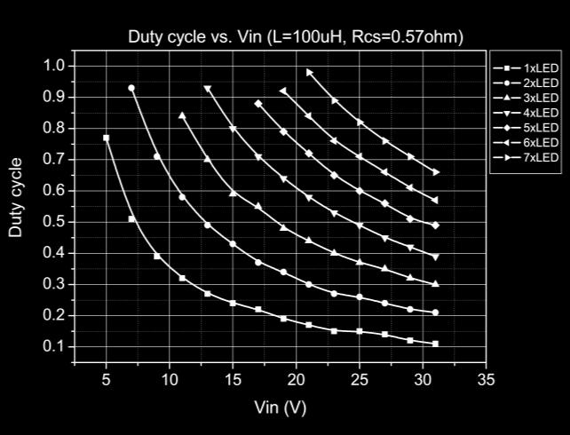
12 off the output and the supply current will fall to a low standby level of 130μA nominal. Soft-start An external capacitor from the IM pin to ground will provide additional soft-start delay, by increasing the time taken for the voltage on this pin to rise to the turn-on threshold and by slowing down the rate of rise of the control voltage at the input of the comparator. Adding capacitance increases this delay by approximately 0.125ms/nF. Inherent open-circuit LE protection If the connection to the LE(s) is open-circuited, the coil is isolated from the SW pin of the chip, so the device and LE will not be damaged. When the LE(s) load is connected the device will enter normal operation. Capacitor selection A low ESR capacitor should be used for input decoupling, as the ESR of this capacitor appears in series with the supply source impedance and lowers overall efficiency. This capacitor has to supply the relatively high peak current to the coil and smooth the current ripple on the input supply. A minimum value of 4.7μF is acceptable if the C input source is close to the device, but higher values will improve performance at lower input voltages, especially when the source impedance is high. For the rectified AC input, the capacitor should be higher than 100μF and the tantalum capacitor is recommended. The input capacitor should be placed as close as possible to the IC. For maximum stability over temperature and voltage, capacitors with X7R, X5R, or better dielectric are recommended. Capacitors with Y5V dielectric are not suitable for decoupling in this application and should NOT be used. A suitable Murata capacitor would be GRM42-2X7R475K -50. The following web sites are useful when finding alternatives: Inductor selection Recommended inductor values for the are in the range 47μH to 100μH. Higher values of inductance are recommended at lower output current in order to minimize errors due to switching delays, which result in increased ripple and lower efficiency. Higher values of inductance also result in a smaller change in output current over the supply voltage range. (See graphs). The inductor should be mounted as close to the device as possible with low resistance connections to the SW and VIN pins. The chosen coil should have a saturation current higher than the peak output current and a continuous current rating above the required mean output current. Following table gives the guideline on inductor selection: Vin 5V-10V 10V-20 V 20V-30V 1 LE 47μH 68μH 100μH 2 LE 68μH 100μH 3 LE 68μH 100μH 4 LE 68μH 68μH 5 LE 47μH 68μH 6 LE 47μH 68μH 7 LE 68μH 8 LE 68μH Saturation current times of load current Suitable coils for use with the are listed in the table below: Part No. L (μh) CR (Ω) I SAT (A) Manufacturer MSS MSS MSS CoilCraft The inductor value should be chosen to maintain operating duty cycle and switch 'on'/'off' times within the specified limits over the supply voltage and load current range. The following equations can be used as a guide. SW Switch 'On' time T ON V IN V LE SW Switch 'Off' time T Where: OFF V LE V L is the coil inductance (H) rl is the coil resistance (Ω) L I I avg ( Rs rl Rsw) L I I ( Rs rl) avg R S is the current sense resistance (Ω) I avg is the required LE current (A) Page 12
 iode selection For maximum efficiency and performance, the rectifier (1) should be a fast low capacitance Schottky diode")
13 ΔI is the coil peak-peak ripple current (A) {Internally set to 0.3 x Iavg} V IN is the supply voltage (V) V LE is the total LE forward voltage (V) R SW is the switch resistance (Ω) {=0.6Ω nominal} V is the diode forward voltage at the required load current (V) iode selection For maximum efficiency and performance, the rectifier (1) should be a fast low capacitance Schottky diode with low reverse leakage at the maximum operating voltage and temperature. They also provide better efficiency than silicon diodes, due to a combination of lower forward voltage and reduced recovery time. It is important to select parts with a peak current rating above the peak coil current and a continuous current rating higher than the maximum output load current. It is very important to consider the reverse leakage of the diode when operating above 85 C. Excess leakage will increase the power dissipation in the device and if close to the load may create a thermal runaway condition. The higher forward voltage and overshoot due to reverse recovery time in silicon diodes will increase the peak voltage on the SW output. If a silicon diode is used, care should be taken to ensure that the total voltage appearing on the SW pin including supply ripple, does not exceed the specified maximum value. The following web sites are useful when finding alternatives: Reducing output ripple Peak to peak ripple current in the LE(s) can be reduced, if required, by shunting a capacitor C LE across the LE(s) as shown below: V IN RS 0.28Ω LE 3W VIN CSN SW L 68μH by a factor three (approx.). Proportionally lower ripple can be achieved with higher capacitor values. Note that the capacitor will not affect operating frequency or efficiency, but it will increase start-up delay and reduce the frequency of dimming, by reducing the rate of rise of LE voltage. By adding this capacitor the current waveform through the LE(s) changes from a triangular ramp to a more sinusoidal version without altering the mean current value. Operation at low supply voltage The internal regulator disables the drive to the switch until the supply has risen above the startup threshold (V UVLO ). Above this threshold, the device will start to operate. However, with the supply voltage below the specified minimum value, the switch duty cycle will be high and the device power dissipation will be at a maximum. Care should be taken to avoid operating the device under such conditions in the application, in order to minimize the risk of exceeding the maximum allowed die temperature. (See next section on thermal considerations). The drive to the switch is turned off when the supply voltage falls below the under-voltage threshold (V UVLO -0.2V). This prevents the switch working with excessive 'on' resistance under conditions where the duty cycle is high. Thermal considerations When operating the device at high ambient temperatures, or when driving maximum load current, care must be taken to avoid exceeding the package power dissipation limits. The graph below gives details for power derating. This assumes the device to be mounted on a 25mm 2 PCB with 1oz copper standing in still air. Power (mw) Max. Power issipation IM GN A value of 1μF will reduce the supply ripple current Ambient Temperature (eg C) Note that the device power dissipation will most often be a maximum at minimum supply voltage. It Page 13
14 will also increase if the efficiency of the circuit is low. This may result from the use of unsuitable coils, or excessive parasitic output capacitance on the switch output. When the application is limited by the internal power dissipation of the device, the ESOP8 package is recommended because of its enhanced power dissipation ability. Thermal shutdown protection To ensure the reliability, the is built with a soft over temperature protection function. when junction temperature more than 135 C the output current begin to decrease until to zero at 150 C. The soft over temperature function protects the IC and avoid the flicker when operation at high temperature. Thermal compensation of output current High luminance LEs often need to be supplied with a temperature compensated current in order to maintain stable and reliable operation at all drive levels. The LEs are usually mounted remotely from the device so,for this reason, the temperature coefficients of the internal circuits for the have been optimized to minimize the change in output current when no compensation is employed. If output current compensation is required, it is possible to use an external temperature sensing network - normally using Negative Temperature Coefficient (NTC) thermistors and/or diodes, mounted very close to the LE(s). The output of the sensing network can be used to drive the IM pin in order to reduce output current with increasing temperature. V IN NTC IM R S 0.28Ω VIN CSN SW GN LE 3W L 68μH Layout considerations Careful PCB layout is critical to achieve low switching losses and stable operation. Use a multilayer board whenever possible for better noise immunity. Minimize ground noise by connecting high-current ground returns, the input bypass-capacitor ground lead, and the output-filter ground lead to a single point (star ground configuration). SW pin The SW pin of the device is a fast switching node, so PCB tracks should be kept as short as possible. To minimize ground 'bounce', the ground pin of the device should be soldered directly to the ground plane. Coil and decoupling capacitors and current sense resistor It is particularly important to mount the coil and the input decoupling capacitor as close to the device pins as possible to minimize parasitic resistance and inductance, which will degrade efficiency. It is also important to minimize any track resistance in series with current sense resistor RS. It s best to connect VIN directly to one end of RS and CSN directly to the opposite end of RS with no other currents flowing in these tracks. It is important that the cathode current of the Schottky diode does not flow in a track between RS and VIN as this may give an apparent higher measure of current than is actual because of track resistance. LE current compensation use NTC Page 14
15 TYPICAL APPLICATION CIRCUIT R S V IN C5-30V 0.57Ω LE 3*1W AC12-18V C IN 100μF L=47μH 5 VIN CSN 4 SW GN IM Fig1 :3X1W application R S V IN C5-30V 0.28Ω LE 3*3W AC12-18V C IN 100μF L=47μH 5 VIN CSN 4 SW GN IM Fig 2: 3X3W application Page 15


16 PACKAGE INFORMATION SOT89-5 Package Symbol Millimeters Inches Min Max Min Max A b b c E E e 1.500TYP 0.059TYP e L Page 16
 0.050(BSC) L 0.400 1.270 0.016 0.")
17 PACKAGE INFORMATION ESOP-8 Package Symbol Millimeters Inches Min Max Min Max A A A b c E E E e 1.270(BSC) 0.050(BSC) L θ Page 17
PIN ASSIGNMENT PIN DESCRIPTIONS PIN No. PIN NAMES DESCRIPTION 1 SW Switch Output. SW is the drain of the internal N-Ch MOSFET switch. 2 GND Signal and
 GENERAL DESCRIPTION The PT4115 is a continuous conduction mode inductive step-down converter, designed for driving single or multiple series connected LED efficiently from a voltage source higher than
SC A LED DRIVER with INTERNAL SWITCH. Features. Description. Applications. Package Information
 1.2A LED DRVER with NTERNAL SWTCH Features Simple low parts count Wide input voltage range: 4V to 40V 1.2A output current Single pin on/off Brightness control by using DC voltage Brightness control by
UM1361S. Hysteretic Buck High Brightness LED Driver with Internal Switch UM1361S SOT23-5. General Description
 Hysteretic Buck High Brightness LED Driver with Internal Switch UM1361S SOT23-5 General Description The UM1361S is a PWM step-down converter with internal power switch, designed for driving single or multiple
Pin Configurations Package Pin Configurations LX 1 5 V IN SOT ADJ 3 4 I SENSE SOT89-5 Pin Description Pin Name NO. Description LX 1 Drain of pow
 700mA LED driver with internal switch General Description The is a continuous mode inductive step-down converter, designed for driving a single LED or multiple series connected LEDs efficiently from a
GA V LED Driver with Temperature Compensation Features. General Description. Applications
 General Description The is a continuous mode inductive step-down converter, designed for driving a single LED or multiple series connected LEDs efficiently from a voltage source higher than the required
RT A, Hysteretic, High Brightness LED Driver with Internal Switch. General Description. Features. Applications. Ordering Information RT8472
 RT8472 1A, Hysteretic, High Brightness LED Driver with Internal Switch General Description The RT8472 is a high efficiency, continuous mode inductive step-down converter, designed for driving single or
AT mA LED Driver w/ Internal Switch
 FEATURES Up to 95% Efficiency 0.1V Current Sense Threshold Voltage 5V to 36V Input Voltage Range Driving up to 30LEDs (1W 10S3P) at DC36V IN Up to 1MHz Oscillation Frequency Continuous 1A Output Capability
700mA LED Driver with Internal Switch
 700mA LED Driver with Internal Switch FP7151 General Description The FP7151 is a continuous mode inductive step down converter. It can driving single or multiple series connected LEDs. The FP7151 includes
EUP A,30V,1.2MHz Step-Down Converter DESCRIPTION FEATURES APPLICATIONS. Typical Application Circuit
 1.2A,30V,1.2MHz Step-Down Converter DESCRIPTION The is current mode, step-down switching regulator capable of driving 1.2A continuous load with excellent line and load regulation. The can operate with
FEATURES. Efficiency (%)
") GENERAL DESCRIPTION The PT4105 is a step-down DC/DC converter designed to operate as a high current LED driver. The PT4105 uses a voltage mode, fixed frequency architecture that guarantees stable operation
GENERAL DESCRIPTION The PT4105 is a step-down DC/DC converter designed to operate as a high current LED driver. The PT4105 uses a voltage mode, fixed frequency architecture that guarantees stable operation
ADT7350. General Description. Features. Applications. Typical Application Circuit. Sep / Rev. 0.
 General Description The ADT7350 is a step-down converter with integrated switching MOSFET. It operates wide input supply voltage range from 4.5V to 24V with 1.2A peak output current. It includes current
2MHz, High-Brightness LED Drivers with Integrated MOSFET and High-Side Current Sense
 General Description The MH1683A/MH1683C step-down constant-current high-brightness LED (HB LED) drivers provide a cost-effective design solution for automotive interior/exterior lighting, architectural
MP A, 50V, 1.2MHz Step-Down Converter in a TSOT23-6
 MP2456 0.5A, 50V, 1.2MHz Step-Down Converter in a TSOT23-6 DESCRIPTION The MP2456 is a monolithic, step-down, switchmode converter with a built-in power MOSFET. It achieves a 0.5A peak-output current over
ADT7350. General Description. Applications. Features. Typical Application Circuit. Aug / Rev. 0.
 General Description The ADT7350 is a step-down converter with integrated switching MOSFET. It operates wide input supply voltage range from 4.5V to 24V with 1.2A peak output current. It includes current
SR A, 30V, 420KHz Step-Down Converter DESCRIPTION FEATURES APPLICATIONS TYPICAL APPLICATION
 SR2026 5A, 30V, 420KHz Step-Down Converter DESCRIPTION The SR2026 is a monolithic step-down switch mode converter with a built in internal power MOSFET. It achieves 5A continuous output current over a
SGM3736 PWM Dimming, 38V Step-Up LED Driver
 GENERAL DESCRIPTION The SGM3736 is a versatile constant current LED driver with a high efficiency step-up converter architecture. The low-side power MOSFET is integrated in the device, significantly shrinking
EUP2511. HQI Boost Converter With 2.1A Switch In Tiny SOT-23 Package FEATURES DESCRIPTION APPLICATIONS. Typical Application Circuit
 HQI Boost Converter With 2.1A Switch In Tiny SOT-23 Package DESCRIPTION The is a high performance current mode, PWM step-up converter. With an internal 2.1A, 150mΩ MOSFET, it can generate 5 at up to 900mA
WD3122EC. Descriptions. Features. Applications. Order information. High Efficiency, 28 LEDS White LED Driver. Product specification
 High Efficiency, 28 LEDS White LED Driver Descriptions The is a constant current, high efficiency LED driver. Internal MOSFET can drive up to 10 white LEDs in series and 3S9P LEDs with minimum 1.1A current
MP A, 55V, 100kHz Step-Down Converter with Programmable Output OVP Threshold
 The Future of Analog IC Technology MP24943 3A, 55V, 100kHz Step-Down Converter with Programmable Output OVP Threshold DESCRIPTION The MP24943 is a monolithic, step-down, switch-mode converter. It supplies
2MHz, High-Brightness LED Drivers with Integrated MOSFET and High-Side Current Sense
 19-414; Rev 1; 9/8 EVALUATION KIT AVAILABLE 2MHz, High-Brightness LED Drivers with General Description The step-down constant-current high-brightness LED (HB LED) drivers provide a cost-effective design
DT V 1A Output 400KHz Boost DC-DC Converter FEATURES GENERAL DESCRIPTION APPLICATIONS ORDER INFORMATION
 GENERAL DESCRIPTION The DT9111 is a 5V in 12V 1A Out step-up DC/DC converter The DT9111 incorporates a 30V 6A N-channel MOSFET with low 60mΩ RDSON. The externally adjustable peak inductor current limit
HM2259D. 2A, 4.5V-20V Input,1MHz Synchronous Step-Down Converter. General Description. Features. Applications. Package. Typical Application Circuit
 HM2259D 2A, 4.5V-20V Input,1MHz Synchronous Step-Down Converter General Description Features HM2259D is a fully integrated, high efficiency 2A synchronous rectified step-down converter. The HM2259D operates
SGM V Step-Up LED Driver
 GENERAL DESCRIPTION The SGM3725 is a versatile constant current LED driver with a high efficiency step-up converter architecture. Unique technology and high 1.35A current limit allow SGM3725 to drive up
PAM2861. Description. Pin Assignments. Features. Applications. A Product Line of. Diodes Incorporated 1A LED DRIVER WITH INTERNAL SWITCH PAM2861
 1A LED DRIVER WITH INTERNAL SWITCH Description Pin Assignments The is a continuous mode inductive step-down converter, designed for driving single or multiple series connected LEDs efficiently from a voltage
UM1660. Low Power DC/DC Boost Converter UM1660S SOT23-5 UM1660DA DFN AAG PHO. General Description
 General Description Low Power DC/DC Boost Converter S SOT23-5 DA DFN6 2.0 2.0 The is a PFM controlled step-up DC-DC converter with a switching frequency up to 1MHz. The device is ideal to generate output
ACT111A. 4.8V to 30V Input, 1.5A LED Driver with Dimming Control GENERAL DESCRIPTION FEATURES APPLICATIONS TYPICAL APPLICATION CIRCUIT
 4.8V to 30V Input, 1.5A LED Driver with Dimming Control FEATURES Up to 92% Efficiency Wide 4.8V to 30V Input Voltage Range 100mV Low Feedback Voltage 1.5A High Output Capacity PWM Dimming 10kHz Maximum
MP A, 24V, 700KHz Step-Down Converter
 The Future of Analog IC Technology MP2371 1.8A, 24V, 700KHz Step-Down Converter DESCRIPTION The MP2371 is a monolithic step-down switch mode converter with a built-in internal power MOSFET. It achieves
eorex (Preliminary) EP3101
 EP3101") (Preliminary) 150 KHz, 3A Asynchronous Step-down Converter Features Output oltage: 3.3, 5, 12 and Adjustable Output ersion Adjustable ersion Output oltage Range, 1.23 to 37 ±4% 150KHz±15% Fixed Switching
(Preliminary) 150 KHz, 3A Asynchronous Step-down Converter Features Output oltage: 3.3, 5, 12 and Adjustable Output ersion Adjustable ersion Output oltage Range, 1.23 to 37 ±4% 150KHz±15% Fixed Switching
Thermally enhanced Low V FB Step-Down LED Driver ADT6780
 Thermally enhanced Low V FB Step-Down LED Driver General Description The is a thermally enhanced current mode step down LED driver. That is designed to deliver constant current to high power LEDs. The
eorex EP MHz, 600mA Synchronous Step-down Converter
 1.5MHz, 600mA Synchronous Step-down Converter Features High Efficiency: Up to 96% 1.5MHz Constant Switching Frequency 600mA Output Current at V IN = 3V Integrated Main Switch and Synchronous Rectifier
MIC2296. General Description. Features. Applications. High Power Density 1.2A Boost Regulator
 High Power Density 1.2A Boost Regulator General Description The is a 600kHz, PWM dc/dc boost switching regulator available in a 2mm x 2mm MLF package option. High power density is achieved with the s internal
EUP A, Synchronous Step-Down Converter DESCRIPTION FEATURES APPLICATIONS. Typical Application Circuit
 2A, Synchronous Step-Down Converter DESCRIPTION The is a 1 MHz fixed frequency synchronous, current-mode, step-down dc-dc converter capable of providing up to 2A output current. The operates from an input
MP A, 55V, 480kHz Step-Down Converter in a TSOT23-6
 The Future of Analog IC Technology DESCRIPTION The MP2459 is a monolithic, step-down, switchmode converter with a built-in power MOSFET. It achieves a 0.5A peak-output current over a wide input supply
EUP MHz, 800mA Synchronous Step-Down Converter with Soft Start
 1.5MHz, 800mA Synchronous Step-Down Converter with Soft Start DESCRIPTION The is a constant frequency, current mode, PWM step-down converter. The device integrates a main switch and a synchronous rectifier
Efficiency (%) Package Temperature Part Number Transport Media SOP8-40 to 85 PT1102ESOH Tape and Reel
 Package Temperature Part Number Transport Media SOP8-40 to 85 PT1102ESOH Tape and Reel") GENERAL DESCRIPTION The PT112 is a CMOS-based fixed frequency step-down DC/DC converter with a built-in internal power MOSFET. It achieves 1A continuous output current over a wide input supply range with
GENERAL DESCRIPTION The PT112 is a CMOS-based fixed frequency step-down DC/DC converter with a built-in internal power MOSFET. It achieves 1A continuous output current over a wide input supply range with
SC122. Low Voltage Synchronous Boost Converter. POWER MANAGEMENT Features. Description. Applications. Typical Application Circuit SC122
 POWER MANAGEMENT Features Input voltage 0.7V to 1.6V Minimum start-up voltage 0.85V Output voltage fixed at 3.3V Peak input current limit 350mA typically Output current 95mA at = 1.6V, 50mA at = 0.9V Efficiency
2MHz High-Brightness LED Drivers with High-Side Current Sense and 5000:1 Dimming
 EVALUATION KIT AVAILABLE MAX16819/MAX16820 General Description The MAX16819/MAX16820, step-down constantcurrent high-brightness LED (HB LED) drivers provide a cost-effective solution for architectural
TFT-LCD DC/DC Converter with Integrated Backlight LED Driver
 TFT-LCD DC/DC Converter with Integrated Backlight LED Driver Description The is a step-up current mode PWM DC/DC converter (Ch-1) built in an internal 1.6A, 0.25Ω power N-channel MOSFET and integrated
WD3119 WD3119. High Efficiency, 40V Step-Up White LED Driver. Descriptions. Features. Applications. Order information 3119 FCYW 3119 YYWW
 High Efficiency, 40V Step-Up White LED Driver Http//:www.sh-willsemi.com Descriptions The is a constant current, high efficiency LED driver. Internal MOSFET can drive up to 10 white LEDs in series and
NEW PRODUCT AL V 1.5A BUCK LED DRIVER. Description. Pin Assignments. Applications. Features AL8860. (Top View)
") 4V 1.5A BUCK LED DRIVER Description The is a hysteresis mode DC/DC step-down converter, designed for driving single or multiple series connected LEDs efficiently from a voltage source higher than the LED
4V 1.5A BUCK LED DRIVER Description The is a hysteresis mode DC/DC step-down converter, designed for driving single or multiple series connected LEDs efficiently from a voltage source higher than the LED
MP2494 2A, 55V, 100kHz Step-Down Converter
 The Future of Analog IC Technology MP2494 2A, 55V, 100kHz Step-Down Converter DESCRIPTION The MP2494 is a monolithic step-down switch mode converter. It achieves 2A continuous output current over a wide
RT A, Hysteretic, High Brightness LED Driver with Internal Switch. Features. General Description. Applications. Ordering Information
 RT8420 1.2A, Hysteretic, High Brightness LED Driver with Internal Switch General Description The RT8420 is a high-efficiency, continuous mode, inductive step-down converter, designed for driving single
DT V 400KHz Boost DC-DC Controller FEATURES GENERAL DESCRIPTION APPLICATIONS ORDER INFORMATION
 GENERAL DESCRIPTION The DT9150 is a 5V step-up DC/DC controller designed capable of deliver over 50V Output with proper external N-MOSFET devices. The DT9150 can work with most Power N-MOSFET devices,
BL V 2.0A 1.3MHz Synchronous Buck Converter
 GENERATION DESCRIPTION The BL9309 is a high-efficiency, DC-to-DC step-down switching regulators, capable of delivering up to 2A of output current. The device operates from an input voltage range of 2.5V
MP2497-A 3A, 50V, 100kHz Step-Down Converter with Programmable Output OVP Threshold
 The Future of Analog IC Technology MP2497-A 3A, 50V, 100kHz Step-Down Converter with Programmable Output OVP Threshold DESCRIPTION The MP2497-A is a monolithic step-down switch mode converter with a programmable
ACT MHz, 600mA Synchronous Step Down Converter in SOT23-5 GENERAL DESCRIPTION FEATURES APPLICATIONS. Data Sheet Rev 0, 5/2006
 Data Sheet Rev 0, 5/2006 ACT6906 1.6MHz, 600mA Synchronous Step Down Converter in SOT23-5 FEATURES High Efficiency - Up to 95% Very Low 24µA Quiescent Current Guaranteed 600mA Output Current 1.6MHz Constant
4.5V to 32V Input High Current LED Driver IC For Buck or Buck-Boost Topology CN5816. Features: SHDN COMP OVP CSP CSN
 4.5V to 32V Input High Current LED Driver IC For Buck or Buck-Boost Topology CN5816 General Description: The CN5816 is a current mode fixed-frequency PWM controller for high current LED applications. The
ACT8310/ A, PWM Step-Down DC/DCs in TDFN GENERAL DESCRIPTION FEATURES APPLICATIONS SYSTEM BLOCK DIAGRAM ACT8311. Rev 4, 08-Feb-2017
 1.5A, PWM Step-Down DC/DCs in TDFN FEATURES Multiple Patents Pending Up to 95% High Efficiency Up to 1.5A Guaranteed Output Current (ACT8311) 1.35MHz Constant Frequency Operation Internal Synchronous Rectifier
MP V, 1.2A, 1.4MHz White LED Driver Buck/Boost Halogen Replacement
 The Future of Analog IC Technology DESCRIPTION The MP81 is a 36V,1.A,white LED driver suitable for either step-down or inverting step-up/down applications. It achieves 1.A peak output current over a wide
MP2313 High Efficiency 1A, 24V, 2MHz Synchronous Step Down Converter
 The Future of Analog IC Technology MP2313 High Efficiency 1A, 24V, 2MHz Synchronous Step Down Converter DESCRIPTION The MP2313 is a high frequency synchronous rectified step-down switch mode converter
V IN : 6 ~ 36V AL8807B CTRL AL8807B. Pin Assignments. Description NEW PRODUCT. Applications. Features. Typical Application Circuit
 HIGH EFFICIENCY 36V 1.3A PWM DIMMABLE BUCK LED DRIVER Description Pin Assignments The AL8807B is a step-down DC/DC converter designed to drive LEDs with a constant current. The device can drive up to 9
1.5MHz, 800mA, High-Efficiency PWM Synchronous Step-Down Converter
 1.5MHz, 800mA, High-Efficiency PWM Synchronous Step-Down Converter Description The is a high efficiency, low-noise, DC-DC step-down pulse width modulated (PWM) converter that goes automatically into PFM
EUP3010/A. 1.5MHz,1A Synchronous Step-Down Converter with Soft Start DESCRIPTION FEATURES APPLICATIONS. Typical Application Circuit
 1.5MHz,1A Synchronous Step-Down Converter with Soft Start DESCRIPTION The is a constant frequency, current mode, PWM step-down converter. The device integrates a main switch and a synchronous rectifier
1.0MHz,24V/2.0A High Performance, Boost Converter
 1.0MHz,24V/2.0A High Performance, Boost Converter General Description The LP6320C is a 1MHz PWM boost switching regulator designed for constant-voltage boost applications. The can drive a string of up
YB1520 Step-up DC-DC Converter, White LED Driver
 Description The YB1520 is a step-up DC-DC converter; operates as current source to drive up to 18 white LEDs in parallel/series configuration. Series connecting of the LEDs provides identical LED currents
MP A, 30V, 420kHz Step-Down Converter
 The Future of Analog IC Technology DESCRIPTION The MP28490 is a monolithic step-down switch mode converter with a built in internal power MOSFET. It achieves 5A continuous output current over a wide input
Constant Current Switching Regulator for White LED
 Constant Current Switching Regulator for White LED FP7201 General Description The FP7201 is a Boost DC-DC converter specifically designed to drive white LEDs with constant current. The device can support
AT V,3A Synchronous Buck Converter
 FEATURES DESCRIPTION Wide 8V to 40V Operating Input Range Integrated 140mΩ Power MOSFET Switches Output Adjustable from 1V to 25V Up to 93% Efficiency Internal Soft-Start Stable with Low ESR Ceramic Output
ACT6311. White LED/OLED Step-Up Converter FEATURES
 White LED/OLED Step-Up Converter FEATURES Adjustable Output Voltage Drives OLEDs or White LEDs 30V High Voltage Switch 1MHz Switching Frequency Tiny Inductors and Capacitors Tiny SOT23-5 Package APPLICATIONS
MP MHz, 700mA, Fixed-Frequency Step-Up Driver for up to 10 White LEDS
 MP3301 1.3MHz, 700mA, Fixed-Frequency Step-Up Driver for up to 10 White LEDS DESCRIPTION The MP3301 is a step-up converter designed to drive WLEDS arrays from a single-cell, lithium-ion battery. The MP3301
ACT MHz, 600mA Synchronous Step Down Converter in SOT23-5 FEATURES GENERAL DESCRIPTION APPLICATIONS. Data Sheet Rev 0, 5/2006
 Data Sheet Rev 0, 5/2006 ACT6907 1.6MHz, 600mA Synchronous Step Down Converter in SOT23-5 FEATURES High Efficiency - Up to 95% Very Low 24µA Quiescent Current Guaranteed 600mA Output Current 1.6MHz Constant
MP A, 24V, 1.4MHz Step-Down White LED Driver
 MP2370 1.2A, 24V, 1.4MHz Step-Down White LED Driver DESCRIPTION The MP2370 is a monolithic step-down white LED driver with a built-in power MOSFET. It achieves 1.2A peak output current over a wide input
SGM2576/SGM2576B Power Distribution Switches
 /B GENERAL DESCRIPTION The and B are integrated typically 100mΩ power switch for self-powered and bus-powered Universal Series Bus (USB) applications. The and B integrate programmable current limiting
MP MHz, 350mA Boost Converter
 The Future of Analog IC Technology MP3209 1.4MHz, 350mA Boost Converter DESCRIPTION The MP3209 is a current mode step up converter intended for small, low power applications. The MP3209 switches at 1.4MHz
P R O D U C T H I G H L I G H T LX7172 LX7172A GND. Typical Application
 D E S C R I P T I O N K E Y F E A T U R E S The are 1.4MHz fixed frequency, current-mode, synchronous PWM buck (step-down) DC-DC converters, capable of driving a 1.2A load with high efficiency, excellent
MP A Fixed Frequency White LED Driver
 The Future of Analog IC Technology DESCRIPTION The is a step-up converter designed for driving up to 39 white LEDs (13 strings of 3 LEDs each) from a 5V system rail. The uses a current mode, fixed frequency
The ASD5001 is available in SOT23-5 package, and it is rated for -40 to +85 C temperature range.
 General Description The ASD5001 is a high efficiency, step up PWM regulator with an integrated 1A power transistor. It is designed to operate with an input Voltage range of 1.8 to 15V. Designed for optimum
EUP A, Synchronous Step-Down Converter DESCRIPTION FEATURES APPLICATIONS. Typical Application Circuit
 3A, Synchronous Step-Down Converter DESCRIPTION The is a 1 MHz fixed frequency synchronous, current-mode, step-down dc-dc converter capable of providing up to 3A output current. The operates from an input
YB1522 Step-up DC-DC Converter White LED Driver
 Description The YB1522 is a step-up DC-DC converter; with wide input voltage range from 3V to 16V, which operates as current source to drive up to 3S7P to 3S1P (V IN at 3V to 5V). Series connecting of
id8603 PFM Step-Up DC-DC Converters with Internal Schottky Diode General Description Applications Features Ordering Information Marking Information
 PFM Step-Up DC-DC Converters with Internal Schottky Diode General Description The compact, high-efficiency, PFM step-up DC- DC converters are available in SOT-89-3,SOT-23-3 and SOT-23-5 packages. They
MP A, 24V, 1.4MHz Step-Down Converter
 The Future of Analog IC Technology DESCRIPTION The MP8368 is a monolithic step-down switch mode converter with a built-in internal power MOSFET. It achieves 1.8A continuous output current over a wide input
T6322A TE CH FEATURES GENERAL DESCRIPTION. Applications LED/Display Back Light Driver Lightings Portable Communication Devices Handheld Electronics
 PWM Control 1.5A Step-Down Converter FEATURES Wide Input Voltage Range: 7V to 30V LED Output Current Up to 1.5A Soft-start Single pin on/off and brightness control using DC voltage or PWM High efficiency
DESCRIPTION FEATURES APPLICATIONS TYPICAL APPLICATION. 500KHz, 18V, 2A Synchronous Step-Down Converter
 DESCRIPTION The is a fully integrated, high-efficiency 2A synchronous rectified step-down converter. The operates at high efficiency over a wide output current load range. This device offers two operation
Built-In OVP White LED Step-up Converter in Tiny Package
 Built-In White LED Step-up Converter in Tiny Package Description The is a step-up DC/DC converter specifically designed to drive white LEDs with a constant current. The device can drive up to 4 LEDs in
2MHz, High-Brightness LED Drivers with Integrated MOSFET and High-Side Current Sense
 19-414; Rev 6; 7/12 EVALUATION KIT AVAILABLE 2MHz, High-Brightness LED Drivers with General Description The step-down constant-current high-brightness LED (HB LED) drivers provide a cost-effective design
FAN2013 2A Low-Voltage, Current-Mode Synchronous PWM Buck Regulator
 FAN2013 2A Low-Voltage, Current-Mode Synchronous PWM Buck Regulator Features 95% Efficiency, Synchronous Operation Adjustable Output Voltage from 0.8V to V IN-1 4.5V to 5.5V Input Voltage Range Up to 2A
December 2012 Rev FEATURES. Fig. 1: XRP7613 Application Diagrams
 December 2012 Rev. 1.2.0 GENERAL DESCRIPTION The XRP7613 is a non-synchronous step down converter with integrated FET optimized to drive high power LEDs at up to 1.2A of continuous current. A wide 7.0V
PRODUCT HIGHLIGHT. C B 10nF L1 4.7 H. R1 49.9k. R2 16.2k. Typical Application
 DESCRIPTION KEY FEATURES The is a 1.4MHz fixed frequency, current mode, PWM buck (stepdown) DC-DC converter, capable of driving a 1.5A load with high efficiency, excellent line and load regulation. The
2A, 23V, 380KHz Step-Down Converter
 2A, 23V, 380KHz Step-Down Converter General Description The is a buck regulator with a built-in internal power MOSFET. It achieves 2A continuous output current over a wide input supply range with excellent
EUP A,30V,500KHz Step-Down Converter DESCRIPTION FEATURES APPLICATIONS. Typical Application Circuit
 5A,30V,500KHz Step-Down Converter DESCRIPTION The is current mode, step-down switching regulator capable of driving 5A continuous load with excellent line and load regulation. The operates with an input
1.5 MHz, 600mA Synchronous Step-Down Converter
 GENERAL DESCRIPTION is a 1.5Mhz constant frequency, slope compensated current mode PWM step-down converter. The device integrates a main switch and a synchronous rectifier for high efficiency without an
EUP A,40V,200KHz Step-Down Converter
 3A,40V,200KHz Step-Down Converter DESCRIPTION The is current mode, step-down switching regulator capable of driving 3A continuous load with excellent line and load regulation. The operates with an input
MP V Input, 1A, Step-Down Converter
 Efficiency(%) MP9486 100V Input, 1A, Step-Down Converter DESCRIPTION The MP9486 is a high-voltage, step-down, switching regulator that delivers up to 1A of continuous current to the load. It integrates
AL8843. Description. Pin Assignments. Applications NEW PRODUCT. Features 40V 3A STEP-DOWN LED DRIVER AL8843
 40V 3A STEP-DOWN LED DRIVER Description Pin Assignments The is a hysteresis mode DC-DC step-down converter, (Top View) designed for driving single or multiple series connected LEDs efficiently from a voltage
T8308 TE CH FEATURES GENERAL DESCRIPTION. Applications LED/Display Back Light Driver Lightings Portable Communication Devices Handheld Electronics
 PWM Control 800mA Step-Down Converter FEATURES Wide Input Voltage Range: 7V to 30V LED Output Current Up to 800mA Soft-start Single pin on/off and brightness control using DC voltage or PWM High efficiency
T8302AX TE CH FEATURES GENERAL DESCRIPTION. Applications LED/Display Back Light Driver Lightings Portable Communication Devices Handheld Electronics
 PWM Control 1A Step-Down Converter FEATURES Wide Input Voltage Range: 6V to 60V LED Output Current Up to 1A Soft-start Single pin on/off and brightness control using DC voltage or PWM High efficiency (up
23V, 1.8A, 1.4MHz Asynchronous Step-Down DC/DC Converter
 23V, 1.8A, 1.4MHz Asynchronous StepDown DC/DC Converter Description The is a monolithic stepdown switch mode converter with a builtin power MOSFET. It achieves 1.8A output current over a wide input supply
MP24833A 55V, 3A, White LED Driver
 The Future of Analog IC Technology DESCRIPTION The MP24833A is a 55V, 3A, white LED driver suitable for step-down, inverting step-up/stepdown, and step-up applications. The MP24833- A achieves 3A of output
MPM V-5.5V, 4A, Power Module, Synchronous Step-Down Converter with Integrated Inductor
 The Future of Analog IC Technology MPM3840 2.8V-5.5V, 4A, Power Module, Synchronous Step-Down Converter with Integrated Inductor DESCRIPTION The MPM3840 is a DC/DC module that includes a monolithic, step-down,
AT MHz 2A SOT-26 Step Up DC-DC Converter
 FEATURES DESCRIPTION up to 93% Efficiency Integrated 80mΩ Power MOSFET 2.3V to 24V Input Voltage 1.2MHz Fixed Switching Frequency Internal 4A Switch Current Limit Adjustable Output Voltage up to 28V Internal
PWM Step-Up DC/DC Converter for Panel Backlight. Features. Fig. 1
 PWM Step-Up DC/DC Converter for Panel Backlight General Description The designed with high efficiency step up DC/DC converter for driving white LEDs. The device can drive up 11 white LEDs from a single
HM8113B. 3A,4.5V-16V Input,500kHz Synchronous Step-Down Converter FEATURES GENERAL DESCRIPTION APPLICATIONS TYPICAL APPLICATION
 3A,4.5-16 Input,500kHz Synchronous Step-Down Converter FEATURES High Efficiency: Up to 96% 500KHz Frequency Operation 3A Output Current No Schottky Diode Required 4.5 to 16 Input oltage Range 0.6 Reference
3A, 23V, 380KHz Step-Down Converter
 3A, 23V, 380KHz Step-Down Converter General Description The is a buck regulator with a built in internal power MOSFET. It achieves 3A continuous output current over a wide input supply range with excellent
NEW PRODUCT AL V 1A STEP-DOWN LED DRIVER. Pin Assignments. Description. Applications. Features AL8862. (Top View)
") 60V 1A STEP-DOWN LED DRIVER Description The is a step-down DC/DC converter designed to drive LEDs with a constant current. The operates with an input supply voltage from 5V to 60V and provides an externally
60V 1A STEP-DOWN LED DRIVER Description The is a step-down DC/DC converter designed to drive LEDs with a constant current. The operates with an input supply voltage from 5V to 60V and provides an externally
High-Efficiency, 40V Step-Up Converters for 2 to 10 White LEDs MAX1553/MAX1554
 EVALUATION KIT AVAILABLE /MAX1554 General Description The /MAX1554 drive white LEDs in series with a constant current to provide efficient display backlighting in cellular phones, PDAs, and other hand-held
RT8476A. Two-Stage Hysteretic LED Driver Controller. Features. General Description. Ordering Information. Applications. Simplified Application Circuit
 RT8476A Two-Stage Hysteretic LED Driver Controller General Description The RT8476A is a two-stage controller with dual gate drivers consist of a Boost converter (first stage) and a Buck converter (second
Low-Noise 4.5A Step-Up Current Mode PWM Converter
 Low-Noise 4.5A Step-Up Current Mode PWM Converter FP6298 General Description The FP6298 is a current mode boost DC-DC converter. It is PWM circuitry with built-in 0.08Ω power MOSFET make this regulator
LDS8710. High Efficiency 10 LED Driver With No External Schottky FEATURES APPLICATION DESCRIPTION TYPICAL APPLICATION CIRCUIT
 High Efficiency 10 LED Driver With No External Schottky FEATURES High efficiency boost converter with the input voltage range from 2.7 to 5.5 V No external Schottky Required (Internal synchronous rectifier*)
AT V Synchronous Buck Converter
 38V Synchronous Buck Converter FEATURES DESCRIPTION Wide 8V to 38V Operating Input Range Integrated two 140mΩ Power MOSFET Switches Feedback Voltage : 220mV Internal Soft-Start / VFB Over Voltage Protection
HM V 2A 500KHz Synchronous Step-Down Regulator
 Features HM8114 Wide 4V to 30V Operating Input Range 2A Continuous Output Current Fixed 500KHz Switching Frequency No Schottky Diode Required Short Protection with Hiccup-Mode Built-in Over Current Limit