CHAPTER 4. Techniques of Circuit Analysis
|
|
|
- Virginia Gray
- 6 years ago
- Views:
Transcription
1 CHAPTER 4 Techniques of Circuit Analysis
2 4.1 Terminology Planar circuits those circuits that can be drawn on a plane with no crossing branches. Figure 4.1 (a) A planar circuit. (b) The same circuit redrawn to verify that it is planar. Figure 4.1 (a) A planar circuit. (b) The same circuit redrawn to verify that it is planar.
3 Describing a Circuit The Vocabulary Figure 4.2 A nonplanar circuit.
4
5 Example 4.1 For the circuit in Fig. 4.3, identify a) all nodes. b) all essential nodes. c) all branches. d) all essential branches. e) all meshes. f) two paths that are not loops or essential branches. g) two loops that are not meshes. Figure 4.3 A circuit illustrating nodes, branches, meshes, paths, and loops.
6 Example 4.1
7 Example 4.1
8 The Systematic Approach An Illustration The circuit has four essential nodes and six essential branches, Figure 4.4 The circuit shown in Fig. 4.3 with six unknown branch currents defined. Figure 4.4 The circuit shown in Fig. 4.3 with six unknown branch currents defined.
9 We use the nodes b, c, and e to get Using the other three meshes gives

10 Rearranging Eqs. 4.1 and 4.2 to facilitate their solution yields the set Note that summing the current at the nth node (g in this example) gives
11 4.2 Introduction to the Node-Voltage Method The optimum choice of the reference node (if one exists) becomes apparent after you have gained some experience using this method. In Fig. 4.5, the lower node connects the most branches, so we use it as the reference node. We flag the chosen reference node with the symbol, as in Fig Figure 4.6 The circuit shown in Fig. 4.5 with a reference node and the node voltages. Figure 4.5 A circuit used to illustrate the node-voltage method of circuit analysis.
12 A node voltage is defined as the voltage rise from the reference node to a nonreference node. For this circuit, we must define two node voltages, which are denoted v 1 and v 2 in Fig. 4.6 Figure 4.6 The circuit shown in Fig. 4.5 with a reference node and the node voltages.
13 Figure 4.7 Computation of the branch current i.
14 The sum of the three currents leaving node 1 must equal zero; therefore the node-voltage equation derived at node 1 is The node-voltage equation derived at node 2 is Solving for v 1 and v 2 yields
15 Example 4.2 a) Use the node-voltage method of circuit analysis to find the branch currents i a, i b, and i c in the circuit shown in Fig b) Find the power associated with each source, and state whether the source is delivering or absorbing power. Figure 4.8 The circuit for Example 4.2.

16 Example 4.2 Figure 4.9 The circuit shown in Fig. 4.8 with a reference node and the unknown node voltage v 1.
17 Example 4.2
18 4.3 The Node-Voltage Method and Dependent Sources If the circuit contains dependent sources, the nodevoltage equations must be supplemented with the constraint equations imposed by the presence of the dependent sources.
19 Example 4.3 Use the node-voltage method to find the power dissipated in the 5 Ω resistor in the circuit shown in Fig Figure 4.10 The circuit for Example 4.3.
20 Example 4.3
21 Example 4.3
22 Example 4.3
23 Example 4.3 Figure 4.11 The circuit shown in Fig. 4.10, with a reference node and the node voltages.
24 4.4 The Node-Voltage Method: Some Special Cases When a voltage source is the only element between two essential nodes, the node-voltage method is simplified. But the 100 V source constrains the voltage between node 1 and the reference node to 100 V. This means that there is only one unknown node voltage (v 2 ). Figure 4.12 A circuit with a known node voltage.
25 But v 1 = 100 V, so Eq. 4.7 can be solved for :
26 Figure 4.13 A circuit with a dependent voltage source connected between nodes. Figure 4.14 The circuit shown in Fig with the selected node voltages defined.
27 Figure 4.14 shows the redrawn circuit, with the reference node flagged and the node voltages defined. Also, we introduce the current i because we cannot express the current in the dependent voltage source branch as a function of the node voltages v 1 and v 2. Thus, at node 2 and at node 3 We eliminate i simply by adding Eqs. 4.9 and 4.10 to get
28 The Concept of a Supernode When a voltage source is between two essential nodes, we can combine those nodes to form a supernode. Figure 4.15 Considering nodes 2 and 3 to be a supernode.
29 Using Eqs and 4.14 and v 1 = 50 V reduces Eq to From Eqs and 4.14:
30 Node-Voltage Analysis of the Amplifier Circuit The circuit has four essential nodes: Nodes a and d are connected by an independent voltage source as are nodes b and c. Figure 4.16 The transistor amplifier circuit shown Figure in Fig The transistor amplifier circuit shown in Fig Figure Figure The circuit The shown circuit in shown Fig. 4.16, in with Fig. voltages 4.16, and with the voltages supernode and identified. the supernode identified.
31 Using d as the reference node, combine nodes b and c into a supernode. We now eliminate both v c and i B from Eq by noting that Substituting Eqs and 4.17 into Eq yields Solving Eq for v b yields
32 4.5 Introduction to the Mesh-Current Method Fig contains seven essential branches where the current is unknown and four essential nodes. Therefore, to solve it via the mesh-current method, we must write four [7-(4-1)] mesh-current equations. A mesh current is the current that exists only in the perimeter of a mesh. Figure 4.18 The circuit Figure 4.18 The circuit shown in Fig. 4.1(b), with the shown in Fig. 4.1(b), with mesh currents defined. the mesh currents defined.
33 The evolution of the mesh current technique Applying Kirchhoff s current law to the upper node and Kirchhoff s voltage law around the two meshes generates the following set of equations: Figure 4.19 A circuit used to illustrate development of the mesh-current method of circuit analysis.
34 Apply Kirchhoff s voltage law around the two meshes Figure 4.20 Mesh currents i a and i b.
35 Collecting the coefficients of i a and i b in Eqs and 4.26 gives
36 Example 4.4 a) Use the mesh-current method to determine the power associated with each voltage source in the circuit shown in Fig b) Calculate the voltage v o across 8 Ω the resistor. Figure 4.21 The circuit for Example 4.4.
37 Example 4.4 Figure 4.22 The three mesh currents used to analyze the circuit shown in Fig
38 Example 4.4
39 Example 4.4
40 4.6 The Mesh-Current Method and dependent Sources If the circuit contains dependent sources, the meshcurrent equations must be supplemented by the appropriate constraint equations.
41 Example 4.5 Use the mesh-current method of circuit analysis to determine the power dissipated in the resistor 4 Ω in the circuit shown in Fig Figure 4.23 The circuit for Example 4.5.

42 Example 4.5 Figure 4.24 The circuit shown in Fig with the three mesh currents.
43 Example 4.5
44 Example 4.5
45 4.7 The Mesh-Current Method: Some Special Cases When a branch includes a current source, the meshcurrent method requires some additional manipulations. Figure 4.25 A circuit illustrating mesh analysis when Figure 4.25 A circuit illustrating mesh a branch contains an independent current source. analysis when a branch contains an independent current source.
46 Thus, for mesh a: and for mesh c: We now add Eqs and 4.37 to eliminate and obtain Summing voltages around mesh b gives
47 We reduce Eqs and 4.39 to two equations and two unknowns by using the constraint that We leave to you the verification that, when Eq is combined with Eqs and 4.39, the solutions for the three mesh currents are
48 The Concept of a Supermesh To create a supermesh, we mentally remove the current source from the circuit by simply avoiding this branch when writing the mesh-current equations. Figure 4.26 The circuit shown in Fig. 4.25, illustrating Figure 4.26 The circuit shown in Fig. 4.25, the concept of a supermesh. illustrating the concept of a supermesh.
49 When we sum the voltages around the supermesh (denoted by the dashed line), we obtain the equation which reduces to Note that Eqs and 4.38 are identical.
50 Mesh-Current Analysis of the Amplifier Circuit In Fig using the concept of the supermesh, we redraw the circuit as shown in Fig Figure 4.27 The circuit shown in Fig. Figure with The the circuit mesh shown currents in Fig i a, with the mesh currents ia, ib, and ic i. b, and i c. Figure 4.28 The circuit shown in Fig. 4.27, depicting the supermesh Figure 4.28 The circuit shown in Fig. 4.27, depicting created the supermesh by the created presence by the presence of the of the dependent current source. dependent current source.
51 We now sum the voltages around the supermesh in terms of the mesh currents i a, i b and i c to obtain The mesh b equation is The constraint imposed by the dependent current source is The branch current controlling the dependent current source, expressed as a function of the mesh currents, is
52 From Eqs and 4.46 We now use Eq to eliminate i c from Eqs and 4.44:
53 You should verify that the solution of Eqs and 4.49 for i a and i b gives We also leave you to verify that, when Eqs and 4.51 are used to find i B, the result is the same as that given by Eq
54 4.8 The Node-Voltage Method Versus the Mesh-Current Method Example 4.6 Find the power dissipated in the 300 Ω resistor in the circuit shown in Fig Figure 4.29 The circuit for Example 4.6.
55 Example 4.6 Figure 4.30 The circuit shown in Fig. 4.29, with the five mesh currents.
56 Example 4.6
57 Example 4.6 Figure 4.31 The circuit shown in Fig. 4.29, with a reference node.
58 Example 4.6

59 Example 4.6 Figure 4.32 The circuit shown in Fig with an alternative reference node.
60 Example 4.6

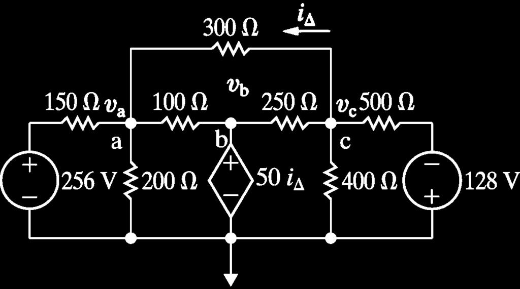
61 Example 4.6
62 Example 4.7 Find the voltage v o in the circuit shown in Fig Figure 4.33 The circuit for Example 4.7.
63 Example 4.7
64 Example 4.7 Figure 4.34 The circuit shown in Fig with the three mesh currents. Figure 4.35 The circuit shown in Fig with node voltages.
65 Example 4.7
66 Example 4.7
67 4.9 Source Transformations Figure 4.36 Source transformations.
68 Example 4.8 a) For the circuit shown in Fig. 4.37, find the power associated with the 6 V source. b) State whether the 6 V source is absorbing or delivering the power calculated in (a). Figure 4.37 The circuit for Example 4.8.
69 Example 4.8

70 Example 4.8

71 Example 4.8 Figure 4.38 Step-by-step simplification of the circuit shown in Fig
72 Example 4.8
73 Example 4.8 Figure 4.39 Equivalent circuits containing a resistance in parallel with a voltage source or in series with a current source.
74 Example 4.9 a) Use source transformations to find the voltage v o in the circuit shown in Fig b) Find the power developed by the 250 V voltage source. c) Find the power developed by the 8 A current source. Figure 4.40 The circuit for Example 4.9.
75 Example 4.9 Figure 4.41 A simplified version of the circuit shown in Fig
76 Example 4.9 Figure 4.42 The circuit shown in Fig after a source transformation. Figure 4.43 The circuit shown in Fig after combining sources and resistors.

77 Example 4.9
 A general circuit. (b) The Thévenin equivalent circuit.")
78 4.10 Thévenin and Norton Equivalents Thévenin equivalent circuit is an independent voltage source in series with a resistor. Figure 4.44 (a) A general circuit. (b) The Thévenin equivalent circuit.

79 Finding a Thévenin Equivalent Figure 4.45 A circuit used to illustrate a Thévenin equivalent.

80 Figure 4.46 The circuit shown in Fig with terminals a and b short-circuited.
81 Figure 4.47 The Thévenin equivalent of the circuit shown in Fig


82 The Norton Equivalent A Norton equivalent circuit consists of an independent current source in parallel with the Norton equivalent resistance. Figure 4.48 Step-by-step derivation of the Thévenin and Norton equivalents of the circuit shown in Fig


83 Figure 4.48 Step-by-step derivation of the Thévenin and Norton equivalents of the circuit shown in Fig

84 Example 4.10 Find the Thévenin equivalent for the circuit containing dependent sources shown in Fig Figure 4.49 A circuit used to illustrate a Thévenin equivalent when the circuit contains dependent sources.
85 Example 4.10

86 Example 4.10 Figure 4.50 The circuit shown in Fig with terminals a and b shortcircuited.
87 Example 4.10

88 Example 4.10 Figure 4.51 The Thévenin equivalent for the circuit shown in Fig


89 4.11 More on Deriving a Thévenin Equivalent Figure 4.52 A circuit used to illustrate a Thévenin equivalent. Figure 4.53 The circuit shown in Fig after deactivation of the independent sources.
90 Example 4.11 Find the Thévenin resistance R TH for the circuit in Fig. 4.49, using the alternative method described.

91 Example 4.11 Figure 4.54 An alternative method for computing the Thévenin resistance.
92 Example 4.11

93 Using the Thévenin Equivalent in the Amplifier Circuit Figure 4.55 The application of a Thévenin equivalent in circuit analysis. Figure 4.56 A modified version of the circuit shown in Fig
94 Now we replace the circuit made up of V CC, R 1 and R 2 with a Thévenin equivalent, with respect to the terminals b,d. The Thévenin voltage and resistance are With the Thévenin equivalent, the circuit in Fig becomes the one shown in Fig
95 Figure 4.57 The circuit shown in Fig modified by a Thévenin equivalent.
96 We now derive an equation for i B simply by summing the voltages around the left mesh. In writing this mesh equation, we recognize that i E = (1 + b)i B. Thus, from which


97 4.12 Maximum Power Transfer Figure 4.58 A circuit describing maximum power transfer. Figure 4.59 A circuit used to determine the value of R L for maximum power transfer.
98
99 Example 4.12 a) For the circuit shown in Fig. 4.60, find the value of R L that results in maximum power being transferred to R L. Figure 4.60 The circuit for Example b) Calculate the maximum power that can be delivered to R L. c) When R L is adjusted for maximum power transfer, what percentage of the power delivered by the 360 V source reaches R L?

100 Example 4.12 Figure 4.61 Reduction of the circuit shown in Fig by means of a Thévenin equivalent.
101 Example 4.12
102 Example 4.12
103 4.13 Superposition An individual response is the result of an independent source acting alone. The principle is applicable to any linear system. Superposition is applied in both the analysis and the design of circuits.
104 Figure 4.62 A circuit used to illustrate superposition. Figure 4.63 The circuit shown in Fig with the current source deactivated.
105
106 Figure 4.64 The circuit shown in Fig with the voltage source deactivated. Figure 4.65 The circuit shown in Fig showing the node voltages υ 3 and υ 4.
107
108
109
110 Example 4.13 Use the principle of superposition to find v o in the circuit shown in Fig Figure 4.66 The circuit for Example 4.13.
111 Example 4.13 Figure 4.67 The circuit shown in Fig with the 5 A source deactivated.
112 Example 4.13
113 Example 4.13 Figure 4.68 The circuit shown in Fig with the 10 V source deactivated.
114 Example 4.13
115 Summary For the topics in this chapter, mastery of some basic terms, and the concepts they represent, is necessary. Those terms are node, essential node, path, branch, essential branch, mesh, and planar circuit. Table 4.1 provides definitions and examples of these terms.
116 Two new circuit analysis techniques were introduced in this chapter: The node-voltage method works with both planar and nonplanar circuits. A reference node is chosen from among the essential nodes. Voltage variables are assigned at the remaining essential nodes, and Kirchhoff s current law is used to write one equation per voltage variable. The number of equations is n e 1, where n e is the number of essential nodes. The mesh-current method works only with planar circuits. Mesh currents are assigned to each mesh, and Kirchhoff s voltage law is used to write one equation per mesh. The number of equations is b (n 1), where b is the number of branches in which the current is unknown, and n is the number of nodes. The mesh currents are used to find the branch currents.
 and a parallel resistor (R) and vice versa. The combinations must be equivalent in terms of their terminal voltage and current.")
117 Summary Several new circuit simplification techniques were introduced in this chapter: Source transformations allow us to exchange a voltage source (v s ) and a series resistor (R) for a current source (i s ) and a parallel resistor (R) and vice versa. The combinations must be equivalent in terms of their terminal voltage and current. Terminal equivalence holds provided that
118 Summary Thévenin equivalents and Norton equivalents allow us to simplify a circuit comprised of sources and resistors into an equivalent circuit consisting of a voltage source and a series resistor (Thévenin) or a current source and a parallel resistor (Norton).The simplified circuit and the original circuit must be equivalent in terms of their terminal voltage and current. Thus keep in mind that (1) the Thévenin voltage (V TH ) is the open-circuit voltage across the terminals of the original circuit, (2) the Thévenin resistance (R TH ) is the ratio of the Thévenin voltage to the shortcircuit current across the terminals of the original circuit; and (3) the Norton equivalent is obtained by performing a source transformation on a Thévenin equivalent.

119 Summary Maximum power transfer is a technique for calculating the maximum value of p that can be delivered to a load, R L. Maximum power transfer occurs when R L = R TH, the Thévenin resistance as seen from the resistor R L. The equation for the maximum power transferred is
120 Summary In a circuit with multiple independent sources, superposition allows us to activate one source at a time and sum the resulting voltages and currents to determine the voltages and currents that exist when all independent sources are active. Dependent sources are never deactivated when applying superposition.
Unit 2. Circuit Analysis Techniques. 2.1 The Node-Voltage Method
 Unit 2 Circuit Analysis Techniques In this unit we apply our knowledge of KVL, KCL and Ohm s Law to develop further techniques for circuit analysis. The material is based on Chapter 4 of the text and that
Announcements. To stop blowing fuses in the lab, note how the breadboards are wired. EECS 42, Spring 2005 Week 3a 1
 Announcements New topics: Mesh (loop) method of circuit analysis Superposition method of circuit analysis Equivalent circuit idea (Thevenin, Norton) Maximum power transfer from a circuit to a load To stop
Techniques of Circuit Analysis
 Techniques of Circuit Analysis Qi Xuan Zhejiang University of Technology October 2015 Electric Circuits 1 Structure Terminology Node- Voltage Method Mesh- Current Method Source Transforma:on Thévenin and
Unit-1(A) Circuit Analysis Techniques
 Circuit Analysis Techniques") Unit-1(A Circuit Analysis Techniques Basic Terms used in a Circuit 1. Node :- It is a point in a circuit where two or more circuit elements are connected together. 2. Branch :- It is that part of a network
Unit-1(A Circuit Analysis Techniques Basic Terms used in a Circuit 1. Node :- It is a point in a circuit where two or more circuit elements are connected together. 2. Branch :- It is that part of a network
What is Mesh Analysis?
 Introduction: What is Mesh Analysis? Mesh Analysis is a technique for the rigourous solution of many electrical circuits. With this method, the user can systematically find sufficient and necessary equations
Lecture # 4 Network Analysis
 CPEN 206 Linear Circuits Lecture # 4 Network Analysis Dr. Godfrey A. Mills Email: gmills@ug.edu.gh Phone: 026-907-3163 February 22, 2016 Course TA David S. Tamakloe 1 What is Network Technique o Network
Unit 8 Combination Circuits
 Unit 8 Combination Circuits Objectives: Define a combination circuit. List the rules for parallel circuits. List the rules for series circuits. Solve for combination circuit values. Characteristics There
EECE251 Circuit Analysis I Lecture Integrated Program Set 2: Methods of Circuit Analysis
 EECE251 Circuit Analysis I Lecture Integrated Program Set 2: Methods of Circuit Analysis Shahriar Mirabbasi Department of Electrical and Computer Engineering University of British Columbia shahriar@ece.ubc.ca
Branch Current Method
 Script Hello friends. In this series of lectures we have been discussing the various types of circuits, the voltage and current laws and their application to circuits. Today in this lecture we shall be
EE 105 Discussion #1: Fundamentals of Circuit Analysis
 EE 105 Discussion #1: Fundamentals of Circuit Analysis 1.1 Ohm s Law V = ir i = V/R 1.2 KCL & KVL Kirchoff s Current Law (KCL) Kirchoff s Voltage Law (KVL) The algebraic sum of all currents entering a
Survival Skills for Circuit Analysis
 P. R. Nelson Fall 2010 WhatToKnow - p. 1/46 Survival Skills for Circuit Analysis What you need to know from ECE 109 Phyllis R. Nelson prnelson@csupomona.edu Professor, Department of Electrical and Computer
Solution: Based on the slope of q(t): 20 A for 0 t 1 s dt = 0 for 3 t 4 s. 20 A for 4 t 5 s 0 for t 5 s 20 C. t (s) 20 C. i (A) Fig. P1.
: 20 A for 0 t 1 s dt = 0 for 3 t 4 s. 20 A for 4 t 5 s 0 for t 5 s 20 C. t (s) 20 C. i (A) Fig. P1.") Problem 1.24 The plot in Fig. P1.24 displays the cumulative charge q(t) that has entered a certain device up to time t. Sketch a plot of the corresponding current i(t). q 20 C 0 1 2 3 4 5 t (s) 20 C Figure
Problem 1.24 The plot in Fig. P1.24 displays the cumulative charge q(t) that has entered a certain device up to time t. Sketch a plot of the corresponding current i(t). q 20 C 0 1 2 3 4 5 t (s) 20 C Figure
5. Handy Circuit Analysis Techniques
 1 5. Handy Circuit Analysis Techniques The nodal and mesh analysis require a complete set of equations to describe a particular circuit, even if only one current, voltage, or power quantity is of interest
Real Analog Chapter 3: Nodal & Mesh Analysis. 3 Introduction and Chapter Objectives. 3.1 Introduction and Terminology
 Real Analog Chapter 3: Nodal & Mesh Analysis 1300 Henley Court Pullman, WA 99163 509.334.6306 www.store.digilent.com 3 Introduction and Chapter Objectives In Chapters 1 & 2, we introduced several tools
Questions Bank of Electrical Circuits
 Questions Bank of Electrical Circuits 1. If a 100 resistor and a 60 XL are in series with a 115V applied voltage, what is the circuit impedance? 2. A 50 XC and a 60 resistance are in series across a 110V
Chapter 3: Resistive Network Analysis Instructor Notes
 Chapter 3: Resistive Network Analysis Instructor Notes Chapter 3 presents the principal topics in the analysis of resistive (DC) circuits The presentation of node voltage and mesh current analysis is supported
Electric Circuits I. Simple Resistive Circuit. Dr. Firas Obeidat
 Electric Circuits I Simple Resistive Circuit Dr. Firas Obeidat 1 Resistors in Series The equivalent resistance of any number of resistors connected in series is the sum of the individual resistances. It
Handy Circuit Analysis Techniques
 CHAPTER 5 Handy Circuit Analysis Techniques KEY CONCEPTS INTRODUCTION The techniques of nodal and mesh analysis described in Chap. 4 are reliable and extremely powerful methods. However, both require that
UNIVERSITY OF NORTH CAROLINA AT CHARLOTTE Department of Electrical and Computer Engineering
 UNIVERSITY OF NORTH CAROLINA AT CHARLOTTE Department of Electrical and Computer Engineering EXPERIMENT 8 NETWORK ANALYSIS OBJECTIVES The purpose of this experiment is to mathematically analyze a circuit
3. Voltage and Current laws
 1 3. Voltage and Current laws 3.1 Node, Branches, and loops A branch represents a single element such as a voltage source or a resistor A node is the point of the connection between two or more elements
ECET 102/CPET101 Lab 11 Thevenin and Norton Circuit Lab. Required Devices and Equipment Resistors: 1k, 2.2k, 3.3k, 3.9k, 10k, and a 5k potentiometer
 ECET 102/CPET101 Lab 11 Thevenin and Norton Circuit Lab Required Devices and Equipment Resistors: 1k, 2.2k, 3.3k, 3.9k, 10k, and a 5k potentiometer Objectives: 1. Calculate the Thevenin equivalent circuit.
Network Theorems. Chapter
 Chapter 10 Network Theorems 10-2: Thevenin s Theorem 10-4: Thevenizing a Bridge Circuit 10-5: Norton s Theorem 10-6: Thevenin-Norton Conversions 10-7: Conversion of Voltage and Current Sources 10-2: Thevenin
electronics fundamentals
 electronics fundamentals circuits, devices, and applications THOMAS L. FLOYD DAVID M. BUCHLA chapter 6 Identifying series-parallel relationships Most practical circuits have combinations of series and
CHAPTER 9. Sinusoidal Steady-State Analysis
 CHAPTER 9 Sinusoidal Steady-State Analysis 9.1 The Sinusoidal Source A sinusoidal voltage source (independent or dependent) produces a voltage that varies sinusoidally with time. A sinusoidal current source
Chapter 26: Direct current circuit
 Chapter 26: Direct current circuit Resistors in circuits Equivalent resistance The nature of the electric potential and current in circuit Kirchhoff s rules (for complicated circuit analysis) Resistors
De Anza College Department of Engineering Engr 37-Intorduction to Circuit Analysis
 De Anza College Department of Engineering Engr 37-Intorduction to Circuit Analysis Spring 2017 Lec: Mon to Thurs 8:15 am 9:20 am S48 Office Hours: Thursday7:15 am to 8:15 am S48 Manizheh Zand email: zandmanizheh@fhda.edu
University f P rtland Sch l f Engineering
 University f P rtland Sch l f Engineering Electric Circuits 101 Wednesday, November 31, 2012 (10312012) Happy Halloween! Copyright by Aziz S. Inan, Ph.D. http://faculty.up.edu/ainan/ Math puzzler # 1:
SCHMITT TRIGGER. Typical ``real world'' signals consist of a superposition of a ``noise'' signal and a
 SCHMITT TRIGGER Typical ``real world'' signals consist of a superposition of a ``noise'' signal and a signal or signals of interest. For example, the signal at the bottom of Figure 19 shows a superposition
CHAPTER 7. Response of First-Order RL and RC Circuits
 CHAPTER 7 Response of First-Order RL and RC Circuits RL and RC Circuits RL (resistor inductor) and RC (resistor-capacitor) circuits. Figure 7.1 The two forms of the circuits for natural response. (a) RL
UEENEEG048B Solve problems in complex multi-path power circuits SAMPLE. Version 4. Training and Education Support Industry Skills Unit Meadowbank
 UEE07 Electrotechnology Training Package UEENEEG048B Solve problems in complex multi-path power circuits Learner guide Version 4 Training and Education Support Industry Skills Unit Meadowbank Product Code:
WALJAT COLLEGES OF APPLIED SCIENCES In academic partnership with BIRLA INSTITUTE OF TECHNOLOGY Question Bank Course: EC Session:
 WLJT OLLEGES OF PPLIED SIENES In academic partnership with IRL INSTITUTE OF TEHNOLOGY Question ank ourse: E Session: 20052006 Semester: II Subject: E2001 asic Electrical Engineering 1. For the resistive
Source Transformations
 Source Transformations Introduction The circuits in this set of problems consist of independent sources, resistors and a meter. In particular, these circuits do not contain dependent sources. Each of these
PH213 Chapter 26 solutions
 PH213 Chapter 26 solutions 26.6. IDENTIFY: The potential drop is the same across the resistors in parallel, and the current into the parallel combination is the same as the current through the 45.0-Ω resistor.
SCRIPT. Voltage Dividers
 SCRIPT Hello friends in our earlier discussion we talked about series resistive circuits, when connected in series, resistors form a "string" in which there is only one path for current. Ohm's law can
Example: In the given circuit: (a) How much power is drawn from the battery? (b) How much current flows through each resistor? And in what direction?
 How much power is drawn from the battery? (b) How much current flows through each resistor? And in what direction?") 0.8 Circuits Wired Partially in Series and Partially in Parallel Example: n the given circuit: (a) How much power is drawn from the battery? (b) How much current flows through each resistor? And in what
0.8 Circuits Wired Partially in Series and Partially in Parallel Example: n the given circuit: (a) How much power is drawn from the battery? (b) How much current flows through each resistor? And in what
ECE 215 Lecture 8 Date:
 ECE 215 Lecture 8 Date: 28.08.2017 Phase Shifter, AC bridge AC Circuits: Steady State Analysis Phase Shifter the circuit current I leads the applied voltage by some phase angle θ, where 0 < θ < 90 ο depending
Chapter Two "Bipolar Transistor Circuits"
 Chapter Two "Bipolar Transistor Circuits" 1.TRANSISTOR CONSTRUCTION:- The transistor is a three-layer semiconductor device consisting of either two n- and one p-type layers of material or two p- and one
PART ONE: DC Circuits
 SEE ONLINE COURSE ON: http://users.utcluj.ro/~denisad PART ONE: DC Circuits Chapter 4. Circuit Theorems Monday, March 12, 2018 1 Contents 1. Superposition Theorem 2. Source Transformation 3. Thevenin s
4.7 k V C 10 V I B. (b) V ma V. 3.3 k ma. (c)
 V ma V. 3.3 k ma. (c)") 380 Chapter 6 Bipolar Junction Transistors (BJTs) Example 6.4 Consider the circuit shown in Fig. 6., which is redrawn in Fig. 6. to remind the reader of the convention employed throughout this book for
380 Chapter 6 Bipolar Junction Transistors (BJTs) Example 6.4 Consider the circuit shown in Fig. 6., which is redrawn in Fig. 6. to remind the reader of the convention employed throughout this book for
Lecture # 3 Circuit Configurations
 CPEN 206 Linear Circuits Lecture # 3 Circuit Configurations Dr. Godfrey A. Mills Email: gmills@ug.edu.gh Phone: 0269073163 February 15, 2016 Course TA David S. Tamakloe CPEN 206 Lecture 3 2015_2016 1 Circuit
VETRI VINAYAHA COLLEGE OF ENGINEERING AND TECHNOLOGY
 VETRI VINAYAHA COLLEGE OF ENGINEERING AND TECHNOLOGY DEPARTMENT OF ELECTRICAL AND ELECTRONICS ENGINEERING I-YEAR/II-SEMESTER- EEE&ECE EE6201- CIRCUIT THEORY Two Marks with Answers PREPARED BY: Mr.A.Thirukkumaran,
Chapter two. Basic Laws. 2.1 Introduction
 2.1 Introduction Chapter two Basic Laws Chapter 1 introduced basic concepts in an electric circuit. To actually determine the values of these variables in a given circuit requires that we understand some
Revision: April 16, E Main Suite D Pullman, WA (509) Voice and Fax
 Voice and Fax") Revision: April 6, 200 25 E Main Suite D Pullman, WA 9963 (509) 334 6306 Voice and Fax Overview In mesh analysis, we will define a set of mesh currents and use Ohm s law to write Kirchoff s voltage law
Revision: April 6, 200 25 E Main Suite D Pullman, WA 9963 (509) 334 6306 Voice and Fax Overview In mesh analysis, we will define a set of mesh currents and use Ohm s law to write Kirchoff s voltage law
30V 30 R1 120V R V 30 R1 120V. Analysis of a single-loop circuit using the KVL method
 Analysis of a singleloop circuit using the KVL method Below is our circuit to analyze. We shall attempt to determine the current through each element, the voltage across each element, and the power delivered
Lab 4. Transistor as an amplifier, part 2
 Lab 4 Transistor as an amplifier, part 2 INTRODUCTION We continue the bi-polar transistor experiments begun in the preceding experiment. In the common emitter amplifier experiment, you will learn techniques
3.4 The Single-Loop Circuit Single-loop circuits
 25 3.4 The Single-Loop Circuit Single-loop circuits Elements are connected in series All elements carry the same current We shall determine The current through each element The voltage across each element
BJT AC Analysis CHAPTER OBJECTIVES 5.1 INTRODUCTION 5.2 AMPLIFICATION IN THE AC DOMAIN
 BJT AC Analysis 5 CHAPTER OBJECTIVES Become familiar with the, hybrid, and hybrid p models for the BJT transistor. Learn to use the equivalent model to find the important ac parameters for an amplifier.
Closed circuit complete path for electrons follow. Open circuit no charge flow and no current.
 Section 1 Schematic Diagrams and Circuits Electric Circuits, continued Closed circuit complete path for electrons follow. Open circuit no charge flow and no current. short circuit closed circuit, no load.
4. Introduction and Chapter Objectives
 Real Analog - Circuits 1 Chapter 4: Systems and Network Theorems 4. Introduction and Chapter Objectives In previous chapters, a number of approaches have been presented for analyzing electrical circuits.
Analog Circuits Prof. Jayanta Mukherjee Department of Electrical Engineering Indian Institute of Technology - Bombay
 Analog Circuits Prof. Jayanta Mukherjee Department of Electrical Engineering Indian Institute of Technology - Bombay Week - 08 Module - 04 BJT DC Circuits Hello, welcome to another module of this course
EE301 - SERIES CIRCUITS, KIRCHHOFF S VOLTAGE LAW
 Learning Objectives a. Identify elements that are connected in series b. State and apply KVL in analysis of a series circuit c. Determine the net effect of series-aiding and series-opposing voltage sources
Chapter 8. Constant Current Sources
 Chapter 8 Methods of Analysis Constant Current Sources Maintains same current in branch of circuit Doesn t matter how components are connected external to the source Direction of current source indicates
Question Paper Profile
 I Scheme Question Paper Profile Program Name : Electrical Engineering Program Group Program Code : EE/EP/EU Semester : Third Course Title : Electrical Circuits Max. Marks : 70 Time: 3 Hrs. Instructions:
Designing Information Devices and Systems I Spring 2019 Lecture Notes Note Introduction to Electrical Circuit Analysis
 EECS 16A Designing Information Devices and Systems I Spring 2019 Lecture Notes Note 11 11.1 Introduction to Electrical Circuit Analysis Our ultimate goal is to design systems that solve people s problems.
Introduction... 1 Part I: Getting Started with Circuit Analysis Part II: Applying Analytical Methods for Complex Circuits...
 Contents at a Glance Introduction... 1 Part I: Getting Started with Circuit Analysis... 5 Chapter 1: Introducing Circuit Analysis...7 Chapter 2: Clarifying Basic Circuit Concepts and Diagrams...15 Chapter
Downloaded from / 1
 PURWANCHAL UNIVERSITY II SEMESTER FINAL EXAMINATION-2008 LEVEL : B. E. (Computer/Electronics & Comm.) SUBJECT: BEG123EL, Electrical Engineering-I Full Marks: 80 TIME: 03:00 hrs Pass marks: 32 Candidates
Kirchhoff s laws. Objectives. Assessment. Assessment. Assessment. Assessment 5/27/14. Apply Kirchhoff s first and second laws.
 Kirchhoff s laws Objectives Apply Kirchhoff s first and second laws. Calculate the current and voltage for resistor circuits connected in parallel. Calculate the current and voltage for resistor circuits
DC Bias. Graphical Analysis. Script
 Course: B.Sc. Applied Physical Science (Computer Science) Year & Sem.: Ist Year, Sem - IInd Subject: Electronics Paper No.: V Paper Title: Analog Circuits Lecture No.: 3 Lecture Title: Analog Circuits
ELECTRICAL CIRCUITS LABORATORY MANUAL (II SEMESTER)
") ELECTRICAL CIRCUITS LABORATORY MANUAL (II SEMESTER) LIST OF EXPERIMENTS. Verification of Ohm s laws and Kirchhoff s laws. 2. Verification of Thevenin s and Norton s Theorem. 3. Verification of Superposition
ELECTRICAL CIRCUITS LABORATORY MANUAL (II SEMESTER) LIST OF EXPERIMENTS. Verification of Ohm s laws and Kirchhoff s laws. 2. Verification of Thevenin s and Norton s Theorem. 3. Verification of Superposition
Homework Assignment 01
 Homework Assignment 01 In this homework set students review some basic circuit analysis techniques, as well as review how to analyze ideal op-amp circuits. Numerical answers must be supplied using engineering
Lab #2 Voltage and Current Division
 In this experiment, we will be investigating the concepts of voltage and current division. Voltage and current division is an application of Kirchoff s Laws. Kirchoff s Voltage Law Kirchoff s Voltage Law
AC : A CIRCUITS COURSE FOR MECHATRONICS ENGINEERING
 AC 2010-2256: A CIRCUITS COURSE FOR MECHATRONICS ENGINEERING L. Brent Jenkins, Southern Polytechnic State University American Society for Engineering Education, 2010 Page 15.14.1 A Circuits Course for
Thevenin Equivalent Circuits: (Material for exam - 3)
") Thevenin Equivalent Circuits: (Material for exam 3) The Thevenin equivalent circuit is a two terminal output circuit that contains only one source called E TH and one series resistors called R TH. This
Thevenin Equivalent Circuits: (Material for exam 3) The Thevenin equivalent circuit is a two terminal output circuit that contains only one source called E TH and one series resistors called R TH. This
ES250: Electrical Science. HW6: The Operational Amplifier
 ES250: Electrical Science HW6: The Operational Amplifier Introduction This chapter introduces the operational amplifier or op amp We will learn how to analyze and design circuits that contain op amps,
Objective of the Lecture
 Objective of the Lecture Present Kirchhoff s Current and Voltage Laws. Chapter 5.6 and Chapter 6.3 Principles of Electric Circuits Chapter4.6 and Chapter 5.5 Electronics Fundamentals or Electric Circuit
Chapter 3: Operational Amplifiers
 Chapter 3: Operational Amplifiers 1 OPERATIONAL AMPLIFIERS Having learned the basic laws and theorems for circuit analysis, we are now ready to study an active circuit element of paramount importance:
EE215 FUNDAMENTALS OF ELECTRICAL ENGINEERING
 EE215 FUNDAMENTALS OF ELECTRICAL ENGINEERING Tai-Chang Chen University of Washington, Bothell Spring 2010 EE215 1 1 WEEK 2 SIMPLE RESISTIVE CIRCUITS April 9 th, 2010 TC Chen UWB 2010 EE215 2 2 QUESTIONS
Analysis and Measurement of a Resistor Bridge Circuit with Three Voltage Sources
 Analysis and Measurement of a Resistor Bridge Circuit with Three Voltage Sources EL 111 - DC Fundamentals Required Laboratory Project By: Walter Banzhaf, E.K. Smith, and Winfield Young University of Hartford
An electronic unit that behaves like a voltagecontrolled
 1 An electronic unit that behaves like a voltagecontrolled voltage source. An active circuit element that amplifies, sums, subtracts, multiply, divide, differentiate or integrates a signal 2 A typical
Combined Series and Parallel Circuits
 Combined Series and Parallel Circuits Objectives: 1. Calculate the equivalent resistance, current, and voltage of series and parallel circuits. 2. Calculate the equivalent resistance of circuits combining
Electric Circuits II Three-Phase Circuits. Dr. Firas Obeidat
 Electric Circuits II Three-Phase Circuits Dr. Firas Obeidat 1 Table of Contents 1 Balanced Three-Phase Voltages 2 Balanced Wye-Wye Connection 3 Balanced Wye-Delta Connection 4 Balanced Delta-Delta Connection
Charge Current Voltage
 ECE110 Introduction to Electronics What is? Charge Current Voltage 1 Kirchhoff s Current Law Current in = Current out Conservation of charge! (What goes in must come out, or the total coming in is zero)
Solving Parallel and Mixed Circuits, and Kirchhoff s Current Law
 Exercise 7 Solving Parallel and Mixed Circuits, and Kirchhoff s Current Law EXERCISE OBJECTIVE When you have completed this exercise, you will be able to calculate the equivalent resistance of multiple
ELEC273 Lecture Notes Set 4, Mesh Analysis
 ELEC273 Lecture Notes Set 4, Mesh Analysis The course web site is: http://users.encs.concordia.ca/~trueman/web_page_273.htm The list of homework problems is in the course outline. For this week: Do these
EE42: Running Checklist of Electronics Terms Dick White
 EE42: Running Checklist of Electronics Terms 14.02.05 Dick White Terms are listed roughly in order of their introduction. Most definitions can be found in your text. Terms2 TERM Charge, current, voltage,
UNIT 1 CIRCUIT ANALYSIS 1 What is a graph of a network? When all the elements in a network is replaced by lines with circles or dots at both ends.
 UNIT 1 CIRCUIT ANALYSIS 1 What is a graph of a network? When all the elements in a network is replaced by lines with circles or dots at both ends. 2 What is tree of a network? It is an interconnected open
AP Physics - Problem Drill 14: Electric Circuits
 AP Physics - Problem Drill 14: Electric Circuits No. 1 of 10 1. Identify the four electric circuit symbols. (A) 1. AC power 2. Battery 3. Light Bulb 4. Resistor (B) 1. Ammeter 2. Resistor 3. AC Power 4.
Common-Emitter Amplifier
 Dr. Charles Kim Common-Emitter Amplifier A. Before We Start As the title of this lab says, this lab is about designing a Common-Emitter Amplifier, and this in this stage of the lab course is premature,
AC Power Instructor Notes
 Chapter 7: AC Power Instructor Notes Chapter 7 surveys important aspects of electric power. Coverage of Chapter 7 can take place immediately following Chapter 4, or as part of a later course on energy
An Oscillator Scheme for Quartz Crystal Characterization.
 An Oscillator Scheme for Quartz Crystal Characterization. Wes Hayward, 15Nov07 The familiar quartz crystal is modeled with the circuit shown below containing a series inductor, capacitor, and equivalent
Lab 5 Kirchhoff s Laws and Superposition
 Lab 5 Kirchhoff s Laws and Superposition In this lab, Kirchhoff s laws will be investigated using a more complex circuit than in the previous labs. Two voltage sources and seven resistors are included
Differential Amp DC Analysis by Robert L Rauck
 Differential Amp DC Analysis by Robert L Rauck Amplifier DC performance is affected by a variety of Op Amp characteristics. Not all of these factors are commonly well understood. This analysis will develop
Sample Question Paper
 Scheme G Sample Question Paper Course Name : Electrical Engineering Group Course Code : EE/EP Semester : Third Subject Title : Electrical Circuit and Network 17323 Marks : 100 Time: 3 hrs Instructions:
fiziks Institute for NET/JRF, GATE, IIT-JAM, M.Sc. Entrance, JEST, TIFR and GRE in Physics
 nstitute for NT/JF, GAT, T-JAM, M.Sc. ntrance, JST, TF and G in Physics 3. ipolar Junction Transistors 3.1 Transistor onstruction Transistor is a three-layer semiconductor device consisting of either two
Source Transformation
 HW Chapter 0: 4, 20, 26, 44, 52, 64, 74, 92. Source Transformation Source transformation in frequency domain involves transforming a voltage source in series with an impedance to a current source in parallel
Transistor Biasing. DC Biasing of BJT. Transistor Biasing. Transistor Biasing 11/23/2018
 Transistor Biasing DC Biasing of BJT Satish Chandra Assistant Professor Department of Physics P P N College, Kanpur www.satish0402.weebly.com A transistors steady state of operation depends a great deal
PROBLEMS. Figure13.74 For Prob Figure13.72 For Prob Figure13.75 For Prob Figure13.73 For Prob Figure13.76 For Prob
 CHAPTER 13 Magnetically Coupled Circuits 571 13.9 In order to match a source with internal impedance of 500 to a 15- load, what is needed is: (a) step-up linear transformer (b) step-down linear transformer
Prelab 4 Millman s and Reciprocity Theorems
 Prelab 4 Millman s and Reciprocity Theorems I. For the circuit in figure (4-7a) and figure (4-7b) : a) Calculate : - The voltage across the terminals A- B with the 1kΩ resistor connected. - The current
ECE 201, Section 3 Lecture 12. Prof. Peter Bermel September 17, 2012
 ECE 201, Section 3 Lecture 12 Prof. Peter ermel September 17, 2012 Exam #1: Thursday, Sep. 20 6:307:30 pm Most of you will be in WTHR 200, unless told otherwise Review session tonight at 8 pm (MTH 175)
EE6201 CIRCUIT THEORY QUESTION BANK PART A
 EE6201 CIRCUIT THEORY 1. State ohm s law. 2. State kirchoff s law. QUESTION BANK PART A 3. Which law is applicable for branch current method? 4. What is the matrix formation equation for mesh and nodal
PART B. t (sec) Figure 1
 Figure 1") Code No: R16128 R16 SET 1 I B. Tech II Semester Regular Examinations, April/May 217 ELECTRICAL CIRCUIT ANALYSIS I (Electrical and Electronics Engineering) Time: 3 hours Max. Marks: 7 Note: 1. Question
Code No: R16128 R16 SET 1 I B. Tech II Semester Regular Examinations, April/May 217 ELECTRICAL CIRCUIT ANALYSIS I (Electrical and Electronics Engineering) Time: 3 hours Max. Marks: 7 Note: 1. Question
Bell Ringer: Define to the best of your ability the definition of: Current Voltage Resistance
 Bell Ringer: Define to the best of your ability the definition of: Current Voltage Resistance Explain the behavior of the current and the voltage in a Series Circuit. Explain the behavior of the current
University of Misan College of Engineering Dep. of Electrical First Stage Fundamental of Elect. Eng. Dr. Malik
 CHAPTER TWO 2. Basic Laws : 2.1. Ohm's Law : Ohm s law states that the voltage (V) across a resistor is directly proportional to the current (I) flowing through the resistor. That is : Where (R) is the
Series-Parallel Circuits
 Series-Parallel Circuits INTRODUCTION A series-parallel configuration is one that is formed by a combination of series and parallel elements. A complex configuration is one in which none of the elements
ENGINEERING CIRCUIT ANALYSIS
 ENGINEERING CIRCUIT ANALYSIS EIGHTH EDITION William H. Hayt, Jr. (deceased) Purdue University Jack E. Kemmerly (deceased) California State University Steven M. Durbin University at Buffalo The State University
ECE ECE285. Electric Circuit Analysis I. Spring Nathalia Peixoto. Rev.2.0: Rev Electric Circuits I
 ECE285 Electric Circuit Analysis I Spring 2014 Nathalia Peixoto Rev.2.0: 140124. Rev 2.1. 140813 1 Lab reports Background: these 9 experiments are designed as simple building blocks (like Legos) and students
Component modeling. Resources and methods for learning about these subjects (list a few here, in preparation for your research):
:") Component modeling This worksheet and all related files are licensed under the Creative Commons Attribution License, version 1.0. To view a copy of this license, visit http://creativecommons.org/licenses/by/1.0/,
Component modeling This worksheet and all related files are licensed under the Creative Commons Attribution License, version 1.0. To view a copy of this license, visit http://creativecommons.org/licenses/by/1.0/,
ENGR 201 Homework, Fall 2018
 Chapter 1 Voltage, Current, Circuit Laws (Selected contents from Chapter 1-3 in the text book) 1. What are the following instruments? Draw lines to match them to their cables: Fig. 1-1 2. Complete the
KINGS COLLEGE OF ENGINEERING DEPARTMENT OF ELECTRICAL AND ELECTRONICS ENGINEERING QUESTION BANK UNIT I BASIC CIRCUITS ANALYSIS PART A (2-MARKS)
") KINGS COLLEGE OF ENGINEERING DEPARTMENT OF ELECTRICAL AND ELECTRONICS ENGINEERING QUESTION BANK YEAR / SEM : I / II SUBJECT CODE & NAME : EE 1151 CIRCUIT THEORY UNIT I BASIC CIRCUITS ANALYSIS PART A (2-MARKS)
KINGS COLLEGE OF ENGINEERING DEPARTMENT OF ELECTRICAL AND ELECTRONICS ENGINEERING QUESTION BANK YEAR / SEM : I / II SUBJECT CODE & NAME : EE 1151 CIRCUIT THEORY UNIT I BASIC CIRCUITS ANALYSIS PART A (2-MARKS)