Adafruit RFM69HCW and RFM9X LoRa Packet Radio Breakouts
|
|
|
- Brenda Berry
- 6 years ago
- Views:
Transcription

1 Adafruit RFM69HCW and RFM9X LoRa Packet Radio Breakouts Created by lady ada Last updated on :09:54 PM UTC
2 Guide Contents Guide Contents Overview Pinouts Power Pins SPI Logic pins: Radio GPIO Antenna Connection Assembly Prepare the header strip: Add the breakout board: And Solder! Antenna Options Wire Antenna ufl Connector ufl SMT Antenna Connector SMA to ufl/u.fl/ipx/ipex RF Adapter Cable SMA Edge-Mount Connector Arduino Wiring Using the RFM69 Radio "Raw" vs Packetized Arduino Libraries RadioHead Library example Basic RX & TX example Basic Transmitter example code Basic receiver example code Radio Freq. Config Configuring Radio Pinout Setup Initializing Radio Basic Transmission Code Basic Receiver Code Basic Receiver/Transmitter Demo w/oled Addressed RX and TX Demo CircuitPython for RFM69 Design Considerations Wiring With Breakout Usage with All-In-One Feather M0 Adafruit Feather M0 RFM69HCW Packet Radio or 915 MHz Adafruit Feather M0 RFM69HCW Packet Radio - 433MHz Module Install Usage Beyond RX & TX CircuitPython for RFM9x LoRa Design Considerations Page 2 of 68
3 Wiring With Breakout Usage with All-In-One Feather M0 Adafruit Feather M0 with RFM95 LoRa Radio - 900MHz Adafruit Feather M0 RFM96 LoRa Radio - 433MHz Module Install Usage Beyond RX & TX RFM9X Test Arduino Library RadioHead RFM9x Library example Basic RX & TX example Transmitter example code Receiver example code Radio Pinout Frequency Setup Initializing Radio Transmission Code Receiver Code Downloads Datasheets & Files Schematic Fabrication Print Radio Range F.A.Q. Which gives better range, LoRa or RFM69? What ranges can I expect for RFM69 radios? What ranges can I expect for RFM9X LoRa radios? I don't seem to be getting the range advetised! Is my module broken? How do I pick/design the right antenna? Page 3 of 68

4 Overview "You see, wire telegraph is a kind of a very, very long cat. You pull his tail in New York and his head is meowing in Los Angeles. Do you understand this? And radio operates exactly the same way: you send signals here, they receive them there. The only difference is that there is no cat." Sending data over long distances is like magic, and now you can be a magician with this range of powerful and easyto-use radio modules. Sure, sometimes you want to talk to a computer (a good time to use WiFi) or perhaps communicate with a Phone (choose Bluetooth Low Energy!) but what if you want to send data very far? Most WiFi, Bluetooth, Zigbee and other wireless chipsets use 2.4GHz, which is great for high speed transfers. If you aren't so concerned about streaming a video, you can use a lower license-free ISM frequency bands such as 433MHz in ITU Europe or 900 MHz in ITU Americas. You can't send data as fast but you can send data a lot farther. Also, these packet radios are simpler than WiFi or BLE, you dont have to associate, pair, scan, or worry about connections. All you do is send data whenever you like, and any other modules tuned to that same frequency (and, with the same encryption key) will receive. The receiver can then send a reply back. The modules do packetization, error correction and can also auto-retransmit so its not like you have worry about everything but less power is wasted on maintaining a link or pairing. These modules are great for use with Arduinos or other microcontrollers, say if you want a sensor node nework or transmit data over a campus or town. The trade off is you need two or more radios, with matching frequencies. WiFi and BT, on the other hand, are commonly included in computers and phones. These radio modules come in four variants (two modulation types and two frequencies) The RFM69's are easiest to work with, and are well known and understood. The LoRa radios are exciting and more powerful but also more expensive. All variants are: Page 4 of 68

5 Packet radio with ready-to-go Arduino libraries Uses the amateur or license-free ISM bands: 433MHz is ITU "Europe" license-free ISM or ITU "American" amateur with limitations. 900MHz is license free ISM for ITU "Americas" Use a simple wire antenna or spot for ufl or SMA radio connector RFM69HCW in either 433 MHz or 868/915MHz These are +20dBm FSK packet radios that have a lot of nice extras in them such as encryption and auto-retransmit. They can go about meters line-of-sight using simple wire antennas, probably up to 5Km with well-tuned directional antennas, perfect line-of-sight, and settings tweakings SX1231 based module with SPI interface +13 to +20 dbm up to 100 mw Power Output Capability (power output selectable in software) 50mA (+13 dbm) to 150mA (+20dBm) current draw for transmissions, ~30mA during active radio listening. The RFM69 radios have a range of approx. 500 meters line of sight with tuned uni-directional antennas. Depending on obstructions, frequency, antenna and power output, you will get lower ranges - especially if you are not line of sight. Create multipoint networks with individual node addresses Encrypted packet engine with AES-128 Page 5 of 68

6 RFM9x LoRa in either 433 MHz or 868/915MHz These are +20dBm LoRa packet radios that have a special radio modulation that is not compatible with the RFM69s but can go much much farther. They can easily go 2 Km line of sight using simple wire antennas, or up to 20Km with directional antennas and settings tweakings SX1276 LoRa based module with SPI interface +5 to +20 dbm up to 100 mw Power Output Capability (power output selectable in software) ~100mA peak during +20dBm transmit, ~30mA during active radio listening. The RFM9x radios have a range of approx. 2 km line of sight with tuned uni-directional antennas. Depending on obstructions, frequency, antenna and power output, you will get lower ranges - especially if you are not line of sight. Page 6 of 68
7 All radios are sold individually and can only talk to radios of the same part number. E.g. RFM MHz can only talk to RFM MHz, LoRa 433 MHz can only talk to LoRa 433, etc. Each radio comes with some header, a 3.3V voltage regulator and levelshifter that can handle 3-5V DC power and logic so you can use it with 3V or 5V devices. Some soldering is required to attach the header. You will need to cut and solder on a small piece of wire (any solid or stranded core is fine) in order to create your antenna. Optionally you can pick up a ufl or SMA edge-mount connector and attach an external duck. Page 7 of 68

8 Pinouts Both RFM69 and RFM9x LoRa breakouts have the exact same pinouts. The silkscreen will say RFM69HCW or LoRa depending on which variant you have. If there's a green or blue dot on top of the module, its 900 MHz. If there's a red dot, its 433 MHz Power Pins Page 8 of 68
9 The left-most pins are used for power Vin - power in. This is regulated down to 3.3V so you can use 3.3-6VDC in. Make sure it can supply 150mA since the peak radio currents can be kinda high GND - ground for logic and power EN - connected to the enable pin of the regulator. Pulled high to Vin by default, pull low to completely cut power to the radio. SPI Logic pins: Page 9 of 68
10 All pins going into the breakout have level shifting circuitry to make them 3-5V logic level safe. Use whatever logic level is on Vin! SCK - This is the SPI Clock pin, its an input to the chip MISO - this is the Master In Slave Out pin, for data sent from the radio to your processor, 3.3V logic level MOSI - this is the Master Out Slave In pin, for data sent from your processor to the radio CS - this is the Chip Select pin, drop it low to start an SPI transaction. Its an input to the chip RST - this is the Reset pin for the radio. It's pulled high by default. Pull down to ground to put it into reset G0 - the radio's "GPIO 0" pin, also known as the IRQ pin, used for interrupt request notification from the radio to the microcontroller, 3.3V logic level Radio GPIO Page 10 of 68
11 The radio's have another 5 GPIO pins that can be used for various notifications or radio functions. These aren't used for the majority of uses but are available in case you want them! All are 3.3V logic with no level shifting Antenna Connection This three-way connection lets you select which kind of Antenna you'd like, from the lowest cost wire dipole to the fanciest SMA Page 11 of 68
12 Page 12 of 68

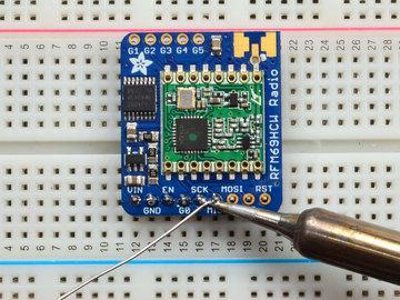
13 Assembly Prepare the header strip: Cut the strip to length if necessary. It will be easier to solder if you insert it into a breadboard - long pins down Page 13 of 68


14 Add the breakout board: Place the breakout board over the pins so that the short pins poke through the breakout pads And Solder! Be sure to solder all pins for reliable electrical contact. (For tips on soldering, be sure to check out our Guide to Excellent Soldering ( Page 14 of 68


15 Page 15 of 68


16 You're done! Check your solder joints visually and continue onto the next steps Antenna Options These radio breakouts do not have a built-in antenna. Instead, you have three options for attaching an antenna. For most low cost radio nodes, a wire works great. If you need to put the radio into an enclosure, soldering in ufl and using a ufl to SMA adapter will let you attach an external antenna. You can also solder an SMA edge-mount connector directly Wire Antenna A wire antenna, aka "quarter wave whip antenna" is low cost and works very well! You just have to cut the wire down to the right length. Cut a stranded or solid core wire the the proper length for the module/frequency 433 MHz inches, or 16.5 cm 868 MHz inches or 8.2 cm 915 MHz - 3 inches or 7.8 cm Page 16 of 68


17 Strip a mm or two off the end of the wire, tin and solder into the ANT pad. Page 17 of 68


18 That's pretty much it, you're done! ufl Connector If you want an external antenna that is a few inches away from the radio, you need to do a tiny bit more work but its not too difficult. You'll need to get an SMT ufl connector, these are fairly standard ufl SMT Antenna Connector $0.75 IN STOCK ADD TO CART You'll also need a ufl to SMA adapter (or whatever adapter you need for the antenna you'll be using, SMA is the most common SMA to ufl/u.fl/ipx/ipex RF Adapter Cable $3.95 IN STOCK ADD TO CART Page 18 of 68

 and a little inlet pad.")
19 Of course, you will also need an antenna of some sort, that matches your radio frequency ufl connectors are rated for 30 connection cycles, but be careful when connecting/disconnecting to not rip the pads off the PCB. Once a ufl/sma adapter is connected, use strain relief! Check the bottom of the ufl connector, note that there's two large side pads (ground) and a little inlet pad. The other small pad is not used! Put down a touch of solder on the signal pad Page 19 of 68


20 Solder in the first pad while holding the ufl steady Solder in the two side pads, they are used for signal and mechanical connectivity so make sure there's plenty of solder Page 20 of 68


21 Once done, check your work visually Once done attach your ufl adapter and antenna! SMA Edge-Mount Connector OK so Page 21 of 68
 Edge-Mount")

22 You'll need an SMA (or, if you need RP-SMA for some reason) Edge-Mount connector with 1.6mm spacing The SMA connector 'slides on' the top of the PCB Page 22 of 68


23 Once lined up, solder the center contact first Solder in the two side ground pads. Note you will need a lot of heat for this, because the connector is an excellent heat sink and its got a huge ground plane Page 23 of 68


24 Flip over and also do the other side ground/mechanical contacts Page 24 of 68


25 Attach on your antenna, you're done! Page 25 of 68

26 Arduino Wiring rfm69.fzz Wiring up the radio in SPI mode is pretty easy as there's not that many pins! The library requires hardware SPI and does not have software SPI support so you must use the hardware SPI port! Start by connecting the power pins Vin connects to the Arduino 5V pin. If you're using a 3.3V Arduino, connect to 3.3V GND connects to Arduino ground CLK connects to SPI clock. On Arduino Uno/Duemilanove/328-based, thats Digital 13. On Mega's, its Digital 52 and on Leonardo/Due its ICSP-3 (See SPI Connections for more details) MISO connects to SPI MISO. On Arduino Uno/Duemilanove/328-based, thats Digital 12. On Mega's, its Digital 50 and on Leonardo/Due its ICSP-1 (See SPI Connections for more details) MOSI connects to SPI MOSI. On Arduino Uno/Duemilanove/328-based, thats Digital 11. On Mega's, its Digital 51 and on Leonardo/Due its ICSP-4 (See SPI Connections for more details) CS connects to our SPI Chip Select pin. We'll be using Digital 4 but you can later change this to any pin RST connects to our radio reset pin. We'll be using Digital 2 but you can later change this pin too. G0 (IRQ) connects to an interrupt-capable pin. We'll be using Digital 3 but you can later change this pin too. However, it must connect a hardware Interrupt pin. Not all pins can do this! Check the board documentation for which pins are hardware interrupts, you'll also need the hardware interrupt number. For example, on UNO digital 3 is interrupt #1 Page 26 of 68


27 Using the RFM69 Radio This page is shared between the RFM69 breakout and the all-in-one Feather RFM69's. The example code and overall functionality is the same, only the pinouts used may differ! Just make sure the example code is using the pins you have wired up. Before beginning make sure you have your Arduino or Feather working smoothly, it will make this part a lot easier. Once you have the basic functionality going - you can upload code, blink an LED, use the serial output, etc. you can then upgrade to using the radio itself. Note that the sub-ghz radio is not designed for streaming audio or video! It's best used for small packets of data. The data rate is adjustable but its common to stick to around 19.2 Kbps (thats bits per second). Lower data rates will be more successful in their transmissions You will, of course, need at least two paired radios to do any testing! The radios must be matched in frequency (e.g. 900 MHz & 900 MHz are ok, 900 MHz & 433 MHz are not). They also must use the same encoding schemes, you cannot have a 900 MHz RFM69 packet radio talk to a 900 MHz RFM9x LoRa radio. "Raw" vs Packetized The SX1231 can be used in a 'raw rx/tx' mode where it just modulates incoming bits from pin #2 and sends them on the radio, however there's no error correction or addressing so we wont be covering that technique. Instead, 99% of cases are best off using packetized mode. This means you can set up a recipient for your data, error correction so you can be sure the whole data set was transmitted correctly, automatic re-transmit retries and return- Page 27 of 68
28 receipt when the packet was delivered. Basically, you get the transparency of a data pipe without the annoyances of radio transmission unreliability Arduino Libraries These radios have really great libraries already written, so rather than coming up with a new standard we suggest using existing libraries such as LowPowerLab's RFM69 Library and AirSpayce's Radiohead library which also suppors a vast number of other radios These are really great Arduino Libraries, so please support both companies in thanks for their efforts! We recommend using the Radiohead library - it is very cross-platform friendly and used a lot in the community! RadioHead Library example To begin talking to the radio, you will need to download our small fork of the Radiohead from our github repository. You can do that by visiting the github repo and manually downloading or, easier, just click this button to download the zip Download RadioHead Library Rename the uncompressed folder RadioHead and check that the RadioHead folder contains files like RH_RFM69.cpp and RH_RFM69.h (and many others!) Place the RadioHead library folder in your arduinosketchfolder/libraries/ folder. You may need to create the libraries subfolder if it's your first library. Restart the IDE. We also have a great tutorial on Arduino library installation at: Basic RX & TX example Lets get a basic demo going, where one radio transmits and the other receives. We'll start by setting up the transmitter Basic Transmitter example code This code will send a small packet of data once a second to another RFM69 radio, without any addressing. Open up the example RadioHead -> feather -> RadioHead69_RawDemo_TX Load this code into your Transmitter Arduino or Feather! Page 28 of 68


29 Before uploading, check for the #define FREQUENCY RF69_915MHZ line and comment that out (and uncomment the line above) to match the frequency of the hardware you're using These examples are optimized for the Feather 32u4/M0. If you're using differnet wiring, uncomment/comment/edit the sections defining the pins depending on which chipset and wiring you are using! The pins used will vary depending on your setup! Once uploaded you should see the following on the serial console Now open up another instance of the Arduino IDE - this is so you can see the serial console output from the TX device while you set up the RX device. Page 29 of 68

30 Basic receiver example code This code will receive and reply with a small packet of data. Open up the example RadioHead -> feather -> RadioHead69_RawDemo_RX Load this code into your Receiver Arduino/Feather! Before uploading, check for the #define FREQUENCY RF69_915MHZ line and comment that out (and uncomment the line above) to match the frequency of the hardware you're using These examples are optimized for the Feather 32u4/M0. If you're using differnet wiring, uncomment/comment/edit the sections defining the pins depending on which chipset and wiring you are using! The pins used will vary depending on your setup! Now open up the Serial console on the receiver, while also checking in on the transmitter's serial console. You should see the receiver is...well, receiving packets Page 30 of 68


31 And, on the transmitter side, it is now printing Got Reply after each transmisssion because it got a reply from the receiver That's pretty much the basics of it! Lets take a look at the examples so you know how to adapt to your own radio network Radio Freq. Config Each radio has a frequency that is configurable in software. You can actually tune outside the recommended frequency, but the range won't be good. 900 MHz can be tuned from about MHz with good performance. 433 MHz radios can be tuned from MHz or so. // Change to or other frequency, must match RX's freq! #define RF69_FREQ Page 31 of 68
32 For all radios they will need to be on the same frequency. If you have a 433MHz radio you will want to stick to 433. If you have a 900 Mhz radio, go with 868 or 915MHz, just make sure all radios are on the same frequency Configuring Radio Pinout At the top of the sketch you can also set the pinout. The radios will use hardware SPI, but you can select any pins for RFM69_CS (an output), RFM_IRQ (an input) and RFM_RST (an output). RFM_RST is manually used to reset the radio at the beginning of the sketch. RFM_IRQ must be an interrupt-capable pin. Check your board to determine which pins you can use! Also, an LED is defined. For example, here is the Feather 32u4 pinout #if defined ( AVR_ATmega32U4 ) // Feather 32u4 w/radio #define RFM69_CS 8 #define RFM69_INT 7 #define RFM69_RST 4 #define LED 13 #endif If you're using a Feather M0, the pinout is slightly different: #if defined(arduino_samd_feather_m0) // Feather M0 w/radio #define RFM69_CS 8 #define RFM69_INT 3 #define RFM69_RST 4 #define LED 13 #endif If you're using an Arduino UNO or compatible, we recommend: #if defined ( AVR_ATmega328P ) // UNO or Feather 328P w/wing #define RFM69_INT 3 // #define RFM69_CS 4 // #define RFM69_RST 2 // "A" #define LED 13 #endif If you're using a FeatherWing or different setup, you'll have to set up the #define statements to match your wiring You can then instantiate the radio object with our custom pin numbers. Note that the IRQ is defined by the IRQ pin not number (sometimes they differ). // Singleton instance of the radio driver RH_RF69 rf69(rfm69_cs, RFM69_INT); Setup We begin by setting up the serial console and hard-resetting the RFM69 Page 32 of 68
33 void setup() { Serial.begin(115200); //while (!Serial) { delay(1); } // wait until serial console is open, remove if not tethered to compute pinmode(led, OUTPUT); pinmode(rfm69_rst, OUTPUT); digitalwrite(rfm69_rst, LOW); Serial.println("Feather RFM69 RX Test!"); Serial.println(); // manual reset digitalwrite(rfm69_rst, HIGH); delay(10); digitalwrite(rfm69_rst, LOW); delay(10); If you are using a board with 'native USB' make sure the while (!Serial) line is commented out if you are not tethering to a computer, as it will cause the microcontroller to halt until a USB connection is made! Initializing Radio Once initialized, you can set up the frequency, transmission power, radio type and encryption key. For the frequency, we set it already at the top of the sketch For transmission power you can select from 14 to 20 dbi. Lower numbers use less power, but have less range. The second argument to the function is whether it is an HCW type radio, with extra amplifier. This should always be set to true! Finally, if you are encrypting data transmission, set up the encryption key if (!rf69.init()) { Serial.println("RFM69 radio init failed"); while (1); } Serial.println("RFM69 radio init OK!"); // Defaults after init are 434.0MHz, modulation GFSK_Rb250Fd250, +13dbM (for low power module) // No encryption if (!rf69.setfrequency(rf69_freq)) { Serial.println("setFrequency failed"); } // If you are using a high power RF69 eg RFM69HW, you *must* set a Tx power with the // ishighpowermodule flag set like this: rf69.settxpower(20, true); // range from for power, 2nd arg must be true for 69HCW // The encryption key has to be the same as the one in the server uint8_t key[] = { 0x01, 0x02, 0x03, 0x04, 0x05, 0x06, 0x07, 0x08, 0x01, 0x02, 0x03, 0x04, 0x05, 0x06, 0x07, 0x08}; rf69.setencryptionkey(key); Page 33 of 68
34 Basic Transmission Code If you are using the transmitter, this code will wait 1 second, then transmit a packet with "Hello World #" and an incrementing packet number, then check for a reply void loop() { delay(1000); // Wait 1 second between transmits, could also 'sleep' here! char radiopacket[20] = "Hello World #"; itoa(packetnum++, radiopacket+13, 10); Serial.print("Sending "); Serial.println(radiopacket); // Send a message! rf69.send((uint8_t *)radiopacket, strlen(radiopacket)); rf69.waitpacketsent(); // Now wait for a reply uint8_t buf[rh_rf69_max_message_len]; uint8_t len = sizeof(buf); } if (rf69.waitavailabletimeout(500)) { // Should be a reply message for us now if (rf69.recv(buf, &len)) { Serial.print("Got a reply: "); Serial.println((char*)buf); Blink(LED, 50, 3); //blink LED 3 times, 50ms between blinks } else { Serial.println("Receive failed"); } } else { Serial.println("No reply, is another RFM69 listening?"); } Its pretty simple, the delay does the waiting, you can replace that with low power sleep code. Then it generates the packet and appends a number that increases every tx. Then it simply calls send() waitpacketsent() to wait until is is done transmitting. It will then wait up to 500 milliseconds for a reply from the receiver with waitavailabletimeout(500). If there is a reply, it will print it out. If not, it will complain nothing was received. Either way the transmitter will continue the loop and sleep for a second until the next TX. Basic Receiver Code The Receiver has the same exact setup code, but the loop is different Page 34 of 68
35 void loop() { if (rf69.available()) { // Should be a message for us now uint8_t buf[rh_rf69_max_message_len]; uint8_t len = sizeof(buf); if (rf69.recv(buf, &len)) { if (!len) return; buf[len] = 0; Serial.print("Received ["); Serial.print(len); Serial.print("]: "); Serial.println((char*)buf); Serial.print("RSSI: "); Serial.println(rf69.lastRssi(), DEC); } } if (strstr((char *)buf, "Hello World")) { // Send a reply! uint8_t data[] = "And hello back to you"; rf69.send(data, sizeof(data)); rf69.waitpacketsent(); Serial.println("Sent a reply"); Blink(LED, 40, 3); //blink LED 3 times, 40ms between blinks } } else { Serial.println("Receive failed"); } Instead of transmitting, it is constantly checking if there's any data packets that have been received. available() will return true if a packet with the proper encryption has been received. If so, the receiver prints it out. It also prints out the RSSI which is the receiver signal strength indicator. This number will range from about -15 to -80. The larger the number (-15 being the highest you'll likely see) the stronger the signal. If the data contains the text "Hello World" it will also reply to the packet. Once done it will continue waiting for a new packet Basic Receiver/Transmitter Demo w/oled OK once you have that going you can try this example, RadioHead69_RawDemoTXRX_OLED. We're using the Feather with an OLED wing but in theory you can run the code without the OLED and connect three buttons to GPIO #9, 6, and 5 on the Feathers. Upload the same code to each Feather. When you press buttons on one Feather they will be printed out on the other one, and vice versa. Very handy for testing bi-directional communication! Page 35 of 68

36 This demo code shows how you can listen for packets and also check for button presses (or sensor data or whatever you like) and send them back and forth between the two radios! Addressed RX and TX Demo OK so the basic demo is well and good but you have to do a lot of management of the connection to make sure packets were received. Instead of manually sending acknowledgements, you can have the RFM69 and library do it for you! Thus the Reliable Datagram part of the RadioHead library. Load up the RadioHead69_AddrDemo_RX and RadioHead69_AddrDemo_TX sketches to each of your boards Don't forget to check the frequency set in the example, and that the pinouts match your wiring!!! This example lets you have many 'client' RFM69's all sending data to one 'server' Each client can have its own address set, as well as the server address. See this code at the beginning: // Where to send packets to! #define DEST_ADDRESS 1 // change addresses for each client board, any number :) #define MY_ADDRESS 2 For each client, have a unique MY_ADDRESS. Then pick one server that will be address #1 Once you upload the code to a client, you'll see the following in the serial console: Page 36 of 68


37 Because the data is being sent to address #1, but #1 is not acknowledging that data. If you have the server running, with no clients, it will sit quietly: Turn on the client and you'll see acknowledged packets! Page 37 of 68
; Which as you can see, is the manager for the RFM69.")
; while (1); } And when transmitting, use sendtowait which will wait for an ack from the recepient (at")
38 And the server is also pretty happy The secret sauce is the addition of this new object: // Class to manage message delivery and receipt, using the driver declared above RHReliableDatagram rf69_manager(rf69, MY_ADDRESS); Which as you can see, is the manager for the RFM69. In setup() you'll need to init it, although you still configure the underlying rfm69 like before: if (!rf69_manager.init()) { Serial.println("RFM69 radio init failed"); while (1); } And when transmitting, use sendtowait which will wait for an ack from the recepient (at DEST_ADDRESS) Page 38 of 68
39 if (rf69_manager.sendtowait((uint8_t *)radiopacket, strlen(radiopacket), DEST_ADDRESS)) { on the 'other side' use the recvfromack which will receive and acknowledge a packet // Wait for a message addressed to us from the client uint8_t len = sizeof(buf); uint8_t from; if (rf69_manager.recvfromack(buf, &len, &from)) { That function will wait forever. If you'd like to timeout while waiting for a packet, use recvfromacktimeout which will wait an indicated # of milliseconds if (rf69_manager.recvfromacktimeout(buf, &len, 2000, &from)) Page 39 of 68
40 CircuitPython for RFM69 It's easy to use the RFM69HCW radio with CircuitPython and the Adafruit CircuitPython RFM69 module. This module allows you to easily write Python code that sends and receives packets of data with the radio. Be careful to note this library is for the RFM69 radio only and will not work with the RFM9X LoRa radios! Design Considerations One thing to be aware of before you use the RFM69 series of radios with CircuitPython are some of the limitations and design considerations for its module. Keep these in mind as you think about projects using the RFM69 and CircuitPython: You can only send and receive packets up to 60 bytes in length at a time. The size of the radio's internal buffer dictates this limit so if you want to send longer messages you'll need to break them into a series of smaller send calls in your application code. Receiving packets is a 'best effort' in pure Python code. Unlike the Arduino versions of the RFM69 library there is no interrupt support which means when a packet is received it must be immediately processed by the Python code or it could be lost. For your application it will work best to only receive small, single packet messages at a time. Don't try to receive kilobytes of data or else you'll lose packets. This module is really intended for simple single packet messages like 'ON', 'OFF', etc. Sending and receiving packets will 'block' your Python code until the packet is fully processed. This means you can't do a lot of other things while sending and waiting for packets to be received. Design your application so the radio usage is the primary scenario and very little other tasks need to happen in the background. The module is written to be compatible with the RadioHead RFM69 Arduino library. This means by default the module will setup the radio with the same GFSK, 250kbit/s, 250khz deviation, and bit whitening radio configuration so it can send and receive data with itself and other RadioHead-driven modules. In addition the CircuitPython module uses the same sync word and packet preamble (4 bytes) as RadioHead. If you want to use different modulations or settings you'll need to configure the radio yourself (see the initialization code for the registers and bits to access, however you will need to consult the datasheet for the necessary values). The CircuitPython module does not support advanced RadioHead features like guaranteed delivery or its internal node addressing scheme. Only the simple 'raw' RadioHead examples are supported (i.e. broadcasting a packet to all listening radios). You can however enable encryption and set an AES encryption key just like with the RadioHead library. If you need guaranteed delivery or other advanced features you'll need to implement them in your application code, or design your application be resilient to failures or missed messages. Wiring With Breakout First wire up a RFM69 breakout to your board as shown on the previous pages for Arduino. Note that the G0/interrupt line is not used by the CircuitPython module and can remain unconnected. Here's an example of wiring a Feather M0 to the radio with a SPI connection: Page 40 of 68
 Usage with All-In-One Feather M0 Alternatively you can use the Feather M0 RFM69 board but be sure you've loaded the adafruit-circuitpythonfeather_m0_rfm69-*.")
41 Board 3V to radio VIN Board GND to radio GND Board SCK to radio SCK Board MOSI to radio MOSI Board MISO to radio MISO Board D5 to radio CS (or any other digital I/O pin) Board D6 to radio RST (or any other digital I/O pin) Usage with All-In-One Feather M0 Alternatively you can use the Feather M0 RFM69 board but be sure you've loaded the adafruit-circuitpythonfeather_m0_rfm69-*.bin version of CircuitPython on your board! This is very important as the RFM69 build has special pins added to the board module which are used to access the radio's control lines! For details on how to load a binary circuitpython build, check out our Non-UF2-Install guide Adafruit Feather M0 RFM69HCW Packet Radio or 915 MHz $24.95 IN STOCK ADD TO CART Page 41 of 68
42 Adafruit Feather M0 RFM69HCW Packet Radio - 433MHz $24.95 IN STOCK ADD TO CART Module Install Next you'll need to install the Adafruit CircuitPython RFM69 module on your CircuitPython board. Before you do that make sure you are running the latest version of Adafruit CircuitPython for your board too (again be sure to the load the Feather M0 RFM69 version if you're using that board and want to use its built-in radio module). Next you'll need to install the necessary libraries to use the hardware--carefully follow the steps to find and install these libraries from Adafruit's CircuitPython library bundle. Our introduction guide has a great page on how to install the library bundle for both express and non-express boards. Remember for non-express boards like the, you'll need to manually install the necessary libraries from the bundle: adafruit_rfm69.mpy adafruit_bus_device You can also download the adafruit_rfm69.mpy from its releases page on Github. Before continuing make sure your board's lib folder or root filesystem has the adafruit_rfm69.mpy, and adafruit_bus_device files and folders copied over. Next connect to the board's serial REPL so you are at the CircuitPython >>> prompt. Usage To demonstrate the usage of the radio we'll initialize it and send and receive data from the board's Python REPL. Run the following code to import the necessary modules and initialize the SPI connection with the sensor: import board import busio import digitalio spi = busio.spi(board.sck, MOSI=board.MOSI, MISO=board.MISO) Now define a few of the pins connected to the RFM69, specifically the CS and RST pins: cs = digitalio.digitalinout(board.d5) reset = digitalio.digitalinout(board.d6) However if you're using the Feather M0 RFM69 board with a built-in RFM69 radio (and you've loaded the special Page 42 of 68
43 version of CircuitPython just for this board as mentioned above), you instead want to use these pins for the CS and RST lines: cs = digitalio.digitalinout(board.rfm69_cs) reset = digitalio.digitalinout(board.rfm69_rst) You're ready to import the RFM69 module and create an instance of the RFM69 class inside it. Before you create the radio module instance you'll need to check if you're using a 433mhz or 915mhz radio module as the initializer requires the frequency to be specified--confirm which frequency your module uses and run one of the following lines. For a 915mhz radio use: import adafruit_rfm69 rfm69 = adafruit_rfm69.rfm69(spi, cs, reset, 915.0) Or for a 433mhz radio use: import adafruit_rfm69 rfm69 = adafruit_rfm69.rfm69(spi, cs, reset, 433.0) Notice the initializer takes the following required parameters: spi - The SPI bus connected to the board. cs - The DigitalInOut instance connected to the CS line of the radio. reset - The DigitalInOut instance connected to the RST or reset line of the radio. frequency - The frequency in megahertz of the radio module. Remember this frequency depends on which type of radio you're using and the frequency you desire to use! In addition there are some optional parameters you might specify: baudrate - The baud rate to use for the SPI connection to the radio. By default this is 10mhz which is as fast as the radio can handle, but in some cases it might be too fast if you're wiring up a breakout to a breadboard (breadboards can be notorious for not working well with high speed signals). If you run into odd errors like being unable to find the RFM69 radio try lowering the baudrate by specifying a baudrate= keyword (which sets the speed to a lower 1mhz value). Once the RFM69 class is created and initialized you're ready to start sending and receiving data. Remember by default the module will be configured to interface with the "RadioHead" RFM69 setup so you can also send and receive packets with an Arduino running the 'raw' TX/RX examples! To send a message simply call the send function and provide a string or byte string of data: rfm69.send('hello world!') Remember you can only send a message up to 60 bytes in length at a time! Attempting to send a message longer than 60 bytes will fail with an exception error. If you need to send a longer message it will have to be broken up into multiple send calls and reconstructed on the receiving side. Page 43 of 68

44 If you have another RFM69 on the same frequency and modulation waiting to receive messages (like another CircuitPython module running receive code below) you should see it receive the message. You can even have an Arduino running the RadioHead library's raw RX example see the message that was sent (be sure this receiving side has an encryption key setup exactly the same way as the sending side, see the encryption_key property discussion further below): To receive a message simply call the receive function. This function will wait for half a second for any packet to be received. If a packet is found it will be returned as a byte string (remember packets are at most 60 bytes long), or if no packet was found a result of None is returned. rfm69.receive() You can increase the amount of time the module waits for a packet to be received by specifying the time in seconds as a parameter to the receive call: rfm69.receive(timeout_s=5.0) # Wait 5 seconds instead of 0.5 seconds. Notice this waits longer at the REPL for a packet to be received before returning. If you have another RFM69 setup try having it send a message while the other is waiting to receive it. You should see a byte string returned. You can also have an Arduino running the RadioHead library's raw TX example send messages that are received by your code (again it must be setup with the same encryption key): Page 44 of 68

45 One thing to note in Python byte strings aren't exactly like text strings and you might not be able to do all the text processing (like find, replace, etc.) as you expect. However you can convert a byte string into text by assuming a specific text encoding like ASCII. For example to receive a packet and convert the contents to an ASCII text string you can run code like: packet = rfm69.receive() # Wait for a packet to be received (up to 0.5 seconds) if packet is not None: packet_text = str(packet, 'ascii') print('received: {0}'.format(packet_text)) Notice this code first receives a packet, then checks if one was actually found (the packet is not None check--if no packet is received a value of None is returned), and then converts the packet data to a string assuming an ASCII text encoding. Beyond RX & TX Beyond basic sending and receiving there are a few properties of the RFM69 class you might want to interact with: encryption_key - This is an optional 16 byte string that defines the AES encryption key used by the radio for sending and receiving packets. Both the sending and receiving code must have the exact same encryption key set or they'll be unable to see each other's packets! See the simpletest.py example below for an example of setting the encryption_key to match the default key from RadioHead library raw examples. By default the RFM69 class assumes no encryption key is set, and you can set this property to the value None to disable encryption. rssi - The received signal strength indicator is a property you can read to see the strength of the radio signal being received. This is updated when packets are received and returns a value in decibels (typically negative, so the smaller the number and closer to 0, the higher the strength / better the signal). That's all there is to the basic RFM69 radio usage! Remember the CircuitPython module is designed for sending and Page 45 of 68
46 receiving small up to 60 byte control messages and not large or high bandwidth amounts of data. Here's a complete example of sending a message and waiting to receive and print any received messages. Save this as main.py on your board and open the serial REPL to see it print data and any received messages. If you have two boards and radios setup to run this code at the same time they'll send each other a message on start up! # Simple example to send a message and then wait indefinitely for messages # to be received. This uses the default RadioHead compatible GFSK_Rb250_Fd250 # modulation and packet format for the radio. # Author: Tony DiCola import board import busio import digitalio import adafruit_rfm69 # Define radio parameters. RADIO_FREQ_MHZ = # Frequency of the radio in Mhz. Must match your # module! Can be a value like 915.0, 433.0, etc. # Define pins connected to the chip, use these if wiring up the breakout according to the guide: CS = digitalio.digitalinout(board.d5) RESET = digitalio.digitalinout(board.d6) # Or uncomment and instead use these if using a Feather M0 RFM69 board and the appropriate CircuitPython #CS = digitalio.digitalinout(board.rfm69_cs) #RESET = digitalio.digitalinout(board.rfm69_rst) # Initialize SPI bus. spi = busio.spi(board.sck, MOSI=board.MOSI, MISO=board.MISO) # Initialze RFM radio rfm69 = adafruit_rfm69.rfm69(spi, CS, RESET, RADIO_FREQ_MHZ) # Optionally set an encryption key (16 byte AES key). MUST match both # on the transmitter and receiver (or be set to None to disable/the default). rfm69.encryption_key = b'\x01\x02\x03\x04\x05\x06\x07\x08\x01\x02\x03\x04\x05\x06\x07\x08' # Print out some chip state: print('temperature: {0}C'.format(rfm69.temperature)) print('frequency: {0}mhz'.format(rfm69.frequency_mhz)) print('bit rate: {0}kbit/s'.format(rfm69.bitrate/1000)) print('frequency deviation: {0}hz'.format(rfm69.frequency_deviation)) # Send a packet. Note you can only send a packet up to 60 bytes in length. # This is a limitation of the radio packet size, so if you need to send larger # amounts of data you will need to break it into smaller send calls. Each send # call will wait for the previous one to finish before continuing. rfm69.send('hello world!\r\n') print('sent hello world message!') # Wait to receive packets. Note that this library can't receive data at a fast # rate, in fact it can only receive and process one 60 byte packet at a time. # This means you should only use this for low bandwidth scenarios, like sending # and receiving a single message at a time. print('waiting for packets...') while True: packet = rfm69.receive() Page 46 of 68
47 # Optionally change the receive timeout from its default of 0.5 seconds: #packet = rfm69.receive(timeout_s=5.0) # If no packet was received during the timeout then None is returned. if packet is None: print('received nothing! Listening again...') else: # Received a packet! # Print out the raw bytes of the packet: print('received (raw bytes): {0}'.format(packet)) # And decode to ASCII text and print it too. Note that you always # receive raw bytes and need to convert to a text format like ASCII # if you intend to do string processing on your data. Make sure the # sending side is sending ASCII data before you try to decode! packet_text = str(packet, 'ascii') print('received (ASCII): {0}'.format(packet_text)) Page 47 of 68
48 CircuitPython for RFM9x LoRa It's easy to use the RFM9x LoRa radio with CircuitPython and the Adafruit CircuitPython RFM9x module. This module allows you to easily write Python code that sends and receives packets of data with the radio. Be careful to note this library is for the RFM95/96/97/98 LoRa radio only and will not work with the simper RFM69 packet radio. Design Considerations One thing to be aware of before you use the RFM9x series of radios with CircuitPython are some of the limitations and design considerations for its module. Keep these in mind as you think about projects using the RFM9x and CircuitPython: You can only send and receive packets up to 252 bytes in length at a time. The size of the radio's internal buffer dictates this limit so if you want to send longer messages you'll need to break them into a series of smaller send calls in your application code. Receiving packets is a 'best effort' in pure Python code. Unlike the Arduino versions of the RFM9x library there is no interrupt support which means when a packet is received it must be immediately processed by the Python code or it could be lost. For your application it will work best to only receive small, single packet messages at a time. Don't try to receive kilobytes of data or else you'll lose packets. This module is really intended for simple single packet messages like 'ON', 'OFF', etc. Sending and receiving packets will 'block' your Python code until the packet is fully processed. This means you can't do a lot of other things while sending and waiting for packets to be received. Design your application so the radio usage is the primary scenario and very little other tasks need to happen in the background. The module is written to be compatible with the RadioHead RFM95 Arduino library. This means by default the module will setup the radio with the same modulation and configuration for transmitting and receiving at the maximum distance with LoRa support. In addition the CircuitPython module uses the same packet preamble (8 bytes) and header (4 bytes) as RadioHead. If you want to use different modulations or settings you'll need to configure the radio yourself after carefully consulting the datasheet. The CircuitPython module does not support advanced RadioHead features like guaranteed delivery or its internal node addressing scheme. Only the simple 'raw' RadioHead examples are supported (i.e. broadcasting a packet to all listening radios). Encryption and sync words are also not supported by the LoRa radio module. You must perform these operations yourself in your application code if they're desired. Wiring With Breakout First wire up a RFM9x breakout to your board as shown on the previous pages for Arduino. Note that the G0/interrupt line is not used by the CircuitPython module and can remain unconnected. Here's an example of wiring a Feather M0 to the radio with a SPI connection: Page 48 of 68
 Usage with All-In-One Feather M0 Alternatively you can use the Feather M0 RFM9x board but be sure you've loaded the adafruit-circuitpythonfeather_m0_rfm9x-*.")
49 Board 3V to radio VIN Board GND to radio GND Board SCK to radio SCK Board MOSI to radio MOSI Board MISO to radio MISO Board D5 to radio CS (or any other digital I/O pin) Board D6 to radio RST (or any other digital I/O pin) Usage with All-In-One Feather M0 Alternatively you can use the Feather M0 RFM9x board but be sure you've loaded the adafruit-circuitpythonfeather_m0_rfm9x-*.bin version of CircuitPython on your board! This is very important as the RFM9x build has special pins added to the board module which are used to access the radio's control lines! For details on how to load a binary circuitpython build, check out our Non-UF2-Install guide Adafruit Feather M0 with RFM95 LoRa Radio - 900MHz $34.95 IN STOCK ADD TO CART Page 49 of 68
50 Adafruit Feather M0 RFM96 LoRa Radio - 433MHz $34.95 IN STOCK ADD TO CART Module Install Next you'll need to install the Adafruit CircuitPython RFM9x module on your CircuitPython board. Before you do that make sure you are running the latest version of Adafruit CircuitPython for your board too (again be sure to the load the Feather M0 RFM9x version if you're using that board and want to use its built-in radio module). Next you'll need to install the necessary libraries to use the hardware--carefully follow the steps to find and install these libraries from Adafruit's CircuitPython library bundle. Our introduction guide has a great page on how to install the library bundle for both express and non-express boards. Remember for non-express boards like the, you'll need to manually install the necessary libraries from the bundle: adafruit_rfm9x.mpy adafruit_bus_device You can also download the adafruit_rfm9x.mpy from its releases page on Github. Before continuing make sure your board's lib folder or root filesystem has the adafruit_rfm9x.mpy, and adafruit_bus_device files and folders copied over. Next connect to the board's serial REPL so you are at the CircuitPython >>> prompt. Usage To demonstrate the usage of the radio we'll initialize it and send and receive data from the board's Python REPL. Run the following code to import the necessary modules and initialize the SPI connection with the radio: import board import busio import digitalio spi = busio.spi(board.sck, MOSI=board.MOSI, MISO=board.MISO) Now define a few of the pins connected to the RFM9x, specifically the CS and RST pins: cs = digitalio.digitalinout(board.d5) reset = digitalio.digitalinout(board.d6) However if you're using the Feather M0 RFM69 board with a built-in RFM9x radio (and you've loaded the special Page 50 of 68
51 version of CircuitPython just for this board as mentioned above), you instead want to use these pins for the CS and RST lines: cs = digitalio.digitalinout(board.rfm9x_cs) reset = digitalio.digitalinout(board.rfm9x_rst) You're ready to import the RFM9x module and create an instance of the RFM9x class inside it. Before you create the radio module instance you'll need to check if you're using a 433mhz or 915mhz radio module as the initializer requires the frequency to be specified--confirm which frequency your module uses and run one of the following lines. For a 915mhz radio use: import adafruit_rfm9x rfm9x = adafruit_rfm9x.rfm9x(spi, cs, reset, 915.0) Or for a 433mhz radio use: import adafruit_rfm9x rfm9x = adafruit_rfm9x.rfm9x(spi, cs, reset, 433.0) Notice the initializer takes the following required parameters: spi - The SPI bus connected to the board. cs - The DigitalInOut instance connected to the CS line of the radio. reset - The DigitalInOut instance connected to the RST or reset line of the radio. frequency - The frequency in megahertz of the radio module. Remember this frequency depends on which type of radio you're using and the frequency you desire to use! In addition there are some optional parameters you might specify: baudrate - The baud rate to use for the SPI connection to the radio. By default this is 10mhz which is as fast as the radio can handle, but in some cases it might be too fast if you're wiring up a breakout to a breadboard (breadboards can be notorious for not working well with high speed signals). If you run into odd errors like being unable to find the RFM9x radio try lowering the baudrate by specifying a baudrate= keyword (which sets the speed to a lower 1mhz value). Once the RFM9x class is created and initialized you're ready to start sending and receiving data. Remember by default the module will be configured to interface with the "RadioHead" RFM9x setup so you can also send and receive packets with an Arduino running the RFM95 TX/RX examples! To send a message simply call the send function and provide a string or byte string of data: rfm9x.send('hello world!') Page 51 of 68
52 Remember you can only send a message up to 252 bytes in length at a time! Attempting to send a message longer than 252 bytes will fail with an exception error. If you need to send a longer message it will have to be broken up into multiple send calls and reconstructed on the receiving side. If you have another RFM9x on the same frequency waiting to receive messages (like another CircuitPython module running receive code below) you should see it receive the message. You can even have an Arduino running the RadioHead library's RFM95 client example see the message that was sent: To receive a message simply call the receive function. This function will wait for half a second for any packet to be received. If a packet is found it will be returned as a byte string (remember packets are at most 252 bytes long), or if no packet was found a result of None is returned. rfm9x.receive() You can increase the amount of time the module waits for a packet to be received by specifying the time in seconds as a parameter to the receive call: rfm9x.receive(timeout_s=5.0) # Wait 5 seconds instead of 0.5 seconds. Notice this waits longer at the REPL for a packet to be received before returning. If you have another RFM9x setup try having it send a message while the other is waiting to receive it. You should see a byte string returned. You can also have an Arduino running the RadioHead library's RFM95 client example send messages that are received by your code: Page 52 of 68

53 One thing to note in Python byte strings aren't exactly like text strings and you might not be able to do all the text processing (like find, replace, etc.) as you expect. However you can convert a byte string into text by assuming a specific text encoding like ASCII. For example to receive a packet and convert the contents to an ASCII text string you can run code like: packet = rfm9x.receive() # Wait for a packet to be received (up to 0.5 seconds) if packet is not None: packet_text = str(packet, 'ascii') print('received: {0}'.format(packet_text)) Notice this code first receives a packet, then checks if one was actually found (the packet is not None check--if no packet is received a value of None is returned), and then converts the packet data to a string assuming an ASCII text encoding. Beyond RX & TX Beyond basic sending and receiving there are a few properties of the RFM69 class you might want to interact with: tx_power - This is a power level (in db) to use when transmitting with the radio. By default this is set to a moderate 13 db value, however you can increase this depending on the type of radio you're using. For high power radios (the modules sold by Adafruit) they support a range of TX power from 5 to 23 db. Try increasing this to the maximum 23 db level (however check your local laws for permission to transmit with such power!) to get the most distance and range. rssi - The received signal strength indicator is a property you can read to see the strength of the radio signal being received. This is updated when packets are received and returns a value in decibels (typically negative, so the smaller the number and closer to 0, the higher the strength / better the signal). That's all there is to the basic RFM9x radio usage! Remember the CircuitPython module is designed for sending and Page 53 of 68
54 receiving small up to 252 byte control messages and not large or high bandwidth amounts of data. Here's a complete example of sending a message and waiting to receive and print any received messages. Save this as main.py on your board and open the serial REPL to see it print data and any received messages. If you have two boards and radios setup to run this code at the same time they'll send each other a message on start up! # Simple demo of sending and recieving data with the RFM95 LoRa radio. # Author: Tony DiCola import board import busio import digitalio import adafruit_rfm9x # Define radio parameters. RADIO_FREQ_MHZ = # Frequency of the radio in Mhz. Must match your # module! Can be a value like 915.0, 433.0, etc. # Define pins connected to the chip, use these if wiring up the breakout according to the guide: CS = digitalio.digitalinout(board.d5) RESET = digitalio.digitalinout(board.d6) # Or uncomment and instead use these if using a Feather M0 RFM9x board and the appropriate # CircuitPython build: #CS = digitalio.digitalinout(board.rfm9x_cs) #RESET = digitalio.digitalinout(board.rfm9x_rst) # Initialize SPI bus. spi = busio.spi(board.sck, MOSI=board.MOSI, MISO=board.MISO) # Initialze RFM radio rfm9x = adafruit_rfm9x.rfm9x(spi, CS, RESET, RADIO_FREQ_MHZ) # Note that the radio is configured in LoRa mode so you can't control sync # word, encryption, frequency deviation, or other settings! # You can however adjust the transmit power (in db). The default is 13 db but # high power radios like the RFM95 can go up to 23 db: rfm9x.tx_power = 23 # Send a packet. Note you can only send a packet up to 252 bytes in length. # This is a limitation of the radio packet size, so if you need to send larger # amounts of data you will need to break it into smaller send calls. Each send # call will wait for the previous one to finish before continuing. rfm9x.send('hello world!\r\n') print('sent hello world message!') # Wait to receive packets. Note that this library can't receive data at a fast # rate, in fact it can only receive and process one 252 byte packet at a time. # This means you should only use this for low bandwidth scenarios, like sending # and receiving a single message at a time. print('waiting for packets...') while True: packet = rfm9x.receive() # Optionally change the receive timeout from its default of 0.5 seconds: #packet = rfm9x.receive(timeout_s=5.0) # If no packet was received during the timeout then None is returned. if packet is None: Page 54 of 68
55 print('received nothing! Listening again...') else: # Received a packet! # Print out the raw bytes of the packet: print('received (raw bytes): {0}'.format(packet)) # And decode to ASCII text and print it too. Note that you always # receive raw bytes and need to convert to a text format like ASCII # if you intend to do string processing on your data. Make sure the # sending side is sending ASCII data before you try to decode! packet_text = str(packet, 'ascii') print('received (ASCII): {0}'.format(packet_text)) # Also read the RSSI (signal strength) of the last received message and # print it. rssi = rfm9x.rssi print('received signal strength: {0} db'.format(rssi)) Page 55 of 68
56 RFM9X Test Note that the sub-ghz radio is not designed for streaming audio or video! It's best used for small packets of data. The data rate is adjustbale but its common to stick to around 19.2 Kbps (thats bits per second). Lower data rates will be more successful in their transmissions You will, of course, need at least two paired radios to do any testing! The radios must be matched in frequency (e.g. 900 MHz & 900 MHz are ok, 900 MHz & 433 MHz are not). They also must use the same encoding schemes, you cannot have a 900 MHz RFM69 packet radio talk to a 900 MHz RFM96 LoRa radio. Arduino Library These radios have really excellent code already written, so rather than coming up with a new standard we suggest using existing libraries such as AirSpayce's Radiohead library which also suppors a vast number of other radios This is a really great Arduino Library, so please support them in thanks for their efforts! RadioHead RFM9x Library example To begin talking to the radio, you will need to download the RadioHead library. You can do that by visiting the github repo and manually downloading or, easier, just click this button to download the zip corresponding to version 1.59 Note that while all the code in the examples below are based on this version you can visit the RadioHead documentation page to get the most recent version which may have bug-fixes or more functionality Download RadioHead v Page 56 of 68
57 Uncompress the zip and find the folder named RadioHead and check that the RadioHead folder contains RH_RF95.cpp and RH_RF95.h (as well as a few dozen other files for radios that are supported) Place the RadioHead library folder your arduinosketchfolder/libraries/ folder. You may need to create the libraries subfolder if its your first library. Restart the IDE. We also have a great tutorial on Arduino library installation at: Basic RX & TX example Lets get a basic demo going, where one Arduino transmits and the other receives. We'll start by setting up the transmitter Transmitter example code This code will send a small packet of data once a second to node address #1 Load this code into your Transmitter Arduino! // LoRa 9x_TX // -*- mode: C++ -*- // Example sketch showing how to create a simple messaging client (transmitter) // with the RH_RF95 class. RH_RF95 class does not provide for addressing or // reliability, so you should only use RH_RF95 if you do not need the higher // level messaging abilities. // It is designed to work with the other example LoRa9x_RX #include <SPI.h> #include <RH_RF95.h> #define RFM95_CS 10 #define RFM95_RST 9 #define RFM95_INT 2 // Change to or other frequency, must match RX's freq! #define RF95_FREQ // Singleton instance of the radio driver RH_RF95 rf95(rfm95_cs, RFM95_INT); void setup() { pinmode(rfm95_rst, OUTPUT); digitalwrite(rfm95_rst, HIGH); while (!Serial); Serial.begin(9600); delay(100); Serial.println("Arduino LoRa TX Test!"); // manual reset digitalwrite(rfm95_rst, LOW); delay(10); digitalwrite(rfm95_rst, HIGH); delay(10); Page 57 of 68
58 delay(10); while (!rf95.init()) { Serial.println("LoRa radio init failed"); while (1); } Serial.println("LoRa radio init OK!"); // Defaults after init are 434.0MHz, modulation GFSK_Rb250Fd250, +13dbM if (!rf95.setfrequency(rf95_freq)) { Serial.println("setFrequency failed"); while (1); } Serial.print("Set Freq to: "); Serial.println(RF95_FREQ); // Defaults after init are 434.0MHz, 13dBm, Bw = 125 khz, Cr = 4/5, Sf = 128chips/symbol, CRC on } // The default transmitter power is 13dBm, using PA_BOOST. // If you are using RFM95/96/97/98 modules which uses the PA_BOOST transmitter pin, then // you can set transmitter powers from 5 to 23 dbm: rf95.settxpower(23, false); int16_t packetnum = 0; // packet counter, we increment per xmission void loop() { Serial.println("Sending to rf95_server"); // Send a message to rf95_server char radiopacket[20] = "Hello World # "; itoa(packetnum++, radiopacket+13, 10); Serial.print("Sending "); Serial.println(radiopacket); radiopacket[19] = 0; Serial.println("Sending..."); delay(10); rf95.send((uint8_t *)radiopacket, 20); Serial.println("Waiting for packet to complete..."); delay(10); rf95.waitpacketsent(); // Now wait for a reply uint8_t buf[rh_rf95_max_message_len]; uint8_t len = sizeof(buf); Serial.println("Waiting for reply..."); delay(10); if (rf95.waitavailabletimeout(1000)) { // Should be a reply message for us now if (rf95.recv(buf, &len)) { Serial.print("Got reply: "); Serial.println((char*)buf); Serial.print("RSSI: "); Serial.println(rf95.lastRssi(), DEC); } else { Serial.println("Receive failed"); } } Page 58 of 68
; } delay(1000); Once uploaded you should see the following on the serial console Now open up another instance of the Arduino IDE - this is so you can see the serial console output from the TX")
59 } } else { Serial.println("No reply, is there a listener around?"); } delay(1000); Once uploaded you should see the following on the serial console Now open up another instance of the Arduino IDE - this is so you can see the serial console output from the TX Arduino while you set up the RX Arduino. Receiver example code This code will receive and acknowledge a small packet of data. Load this code into your Receiver Arduino! // Arduino9x_RX // -*- mode: C++ -*- // Example sketch showing how to create a simple messaging client (receiver) // with the RH_RF95 class. RH_RF95 class does not provide for addressing or // reliability, so you should only use RH_RF95 if you do not need the higher // level messaging abilities. // It is designed to work with the other example Arduino9x_TX #include <SPI.h> #include <RH_RF95.h> #define RFM95_CS 10 #define RFM95_RST 9 #define RFM95_INT 2 Page 59 of 68
60 // Change to or other frequency, must match RX's freq! #define RF95_FREQ // Singleton instance of the radio driver RH_RF95 rf95(rfm95_cs, RFM95_INT); // Blinky on receipt #define LED 13 void setup() { pinmode(led, OUTPUT); pinmode(rfm95_rst, OUTPUT); digitalwrite(rfm95_rst, HIGH); while (!Serial); Serial.begin(9600); delay(100); Serial.println("Arduino LoRa RX Test!"); // manual reset digitalwrite(rfm95_rst, LOW); delay(10); digitalwrite(rfm95_rst, HIGH); delay(10); while (!rf95.init()) { Serial.println("LoRa radio init failed"); while (1); } Serial.println("LoRa radio init OK!"); // Defaults after init are 434.0MHz, modulation GFSK_Rb250Fd250, +13dbM if (!rf95.setfrequency(rf95_freq)) { Serial.println("setFrequency failed"); while (1); } Serial.print("Set Freq to: "); Serial.println(RF95_FREQ); // Defaults after init are 434.0MHz, 13dBm, Bw = 125 khz, Cr = 4/5, Sf = 128chips/symbol, CRC on } // The default transmitter power is 13dBm, using PA_BOOST. // If you are using RFM95/96/97/98 modules which uses the PA_BOOST transmitter pin, then // you can set transmitter powers from 5 to 23 dbm: rf95.settxpower(23, false); void loop() { if (rf95.available()) { // Should be a message for us now uint8_t buf[rh_rf95_max_message_len]; uint8_t len = sizeof(buf); if (rf95.recv(buf, &len)) { digitalwrite(led, HIGH); Page 60 of 68
, DEC); } } // Send a reply uint8_t data[] = \"And hello back to you\"; rf95.send(data, sizeof(data)); rf95.waitpacketsent(); Serial.")
61 digitalwrite(led, HIGH); RH_RF95::printBuffer("Received: ", buf, len); Serial.print("Got: "); Serial.println((char*)buf); Serial.print("RSSI: "); Serial.println(rf95.lastRssi(), DEC); } } // Send a reply uint8_t data[] = "And hello back to you"; rf95.send(data, sizeof(data)); rf95.waitpacketsent(); Serial.println("Sent a reply"); digitalwrite(led, LOW); } else { Serial.println("Receive failed"); } Now open up the Serial console on the receiver, while also checking in on the transmitter's serial console. You should see the receiver is...well, receiving packets You can see that the library example prints out the hex-bytes received C 6C 6F F 72 6C , as well as the ASCII 'string' Hello World. Then it will send a reply. And, on the transmitter side, it is now printing that it got a reply after each transmisssion And hello back to you because it got a reply from the receiver Page 61 of 68

62 That's pretty much the basics of it! Lets take a look at the examples so you know how to adapt to your own radio setup Radio Pinout This is the pinout setup - you can change around the reset and CS pins to any pin. the IRQ pin should be an interrupt pin. On an UNO this is pin #2 or pin #3. Each chipset has different interrupt pins! #define RFM95_CS 10 #define RFM95_RST 9 #define RFM95_INT 2 Frequency You can dial in the frequency you want the radio to communicate on, such as 915.0, or or any number really. Different countries/itu Zones have different ISM bands so make sure you're using those or if you are licensed, those frequencies you may use // Change to or other frequency, must match RX's freq! #define RF95_FREQ You can then instantiate the radio object with our custom pin numbers. // Singleton instance of the radio driver RH_RF95 rf95(rfm95_cs, RFM95_INT); Setup We begin by setting up the serial console and hard-resetting the Radio Page 62 of 68
63 void setup() { pinmode(led, OUTPUT); pinmode(rfm95_rst, OUTPUT); digitalwrite(rfm95_rst, HIGH); while (!Serial); // wait until serial console is open, remove if not tethered to computer Serial.begin(9600); delay(100); Serial.println("Arduino LoRa RX Test!"); // manual reset digitalwrite(rfm95_rst, LOW); delay(10); digitalwrite(rfm95_rst, HIGH); delay(10); Remove the while (!Serial); line if you are not tethering to a computer, as it will cause the Arduino to halt until a USB connection is made! Initializing Radio The library gets initialized with a call to init(). Once initialized, you can set the frequency. You can also configure the output power level, the number ranges from 5 to 23. Start with the highest power level (23) and then scale down as necessary while (!rf95.init()) { Serial.println("LoRa radio init failed"); while (1); } Serial.println("LoRa radio init OK!"); // Defaults after init are 434.0MHz, modulation GFSK_Rb250Fd250, +13dbM if (!rf95.setfrequency(rf95_freq)) { Serial.println("setFrequency failed"); while (1); } Serial.print("Set Freq to: "); Serial.println(RF95_FREQ); // Defaults after init are 434.0MHz, 13dBm, Bw = 125 khz, Cr = 4/5, Sf = 128chips/symbol, CRC on // The default transmitter power is 13dBm, using PA_BOOST. // If you are using RFM95/96/97/98 modules which uses the PA_BOOST transmitter pin, then // you can set transmitter powers from 5 to 23 dbm: rf95.settxpower(23, false); Transmission Code If you are using the transmitter, this code will wait 1 second, then transmit a packet with "Hello World #" and an incrementing packet number Page 63 of 68
64 void loop() { delay(1000); // Wait 1 second between transmits, could also 'sleep' here! Serial.println("Transmitting..."); // Send a message to rf95_server char radiopacket[20] = "Hello World # "; itoa(packetnum++, radiopacket+13, 10); Serial.print("Sending "); Serial.println(radiopacket); radiopacket[19] = 0; Serial.println("Sending..."); delay(10); rf95.send((uint8_t *)radiopacket, 20); Serial.println("Waiting for packet to complete..."); delay(10); rf95.waitpacketsent(); Its pretty simple, the delay does the waiting, you can replace that with low power sleep code. Then it generates the packet and appends a number that increases every tx. Then it simply calls send to transmit the data, and passes in the array of data and the length of the data. Note that this does not any addressing or subnetworking - if you want to make sure the packet goes to a particular radio, you may have to add an identifier/address byte on your own! Then you call waitpacketsent() to wait until the radio is done transmitting. You will not get an automatic acknowledgement, from the other radio unless it knows to send back a packet. Think of it like the 'UDP' of radio - the data is sent, but its not certain it was received! Also, there will not be any automatic retries. Receiver Code The Receiver has the same exact setup code, but the loop is different void loop() { if (rf95.available()) { // Should be a message for us now uint8_t buf[rh_rf95_max_message_len]; uint8_t len = sizeof(buf); if (rf95.recv(buf, &len)) { digitalwrite(led, HIGH); RH_RF95::printBuffer("Received: ", buf, len); Serial.print("Got: "); Serial.println((char*)buf); Serial.print("RSSI: "); Serial.println(rf95.lastRssi(), DEC); Instead of transmitting, it is constantly checking if there's any data packets that have been received. available() will return true if a packet with proper error-correction was received. If so, the receiver prints it out in hex and also as a 'character string' It also prints out the RSSI which is the receiver signal strength indicator. This number will range from about -15 to about The larger the number (-15 being the highest you'll likely see) the stronger the signal. Page 64 of 68
65 Once done it will automatically reply, which is a way for the radios to know that there was an acknowledgement // Send a reply uint8_t data[] = "And hello back to you"; rf95.send(data, sizeof(data)); rf95.waitpacketsent(); Serial.println("Sent a reply"); It simply sends back a string and waits till the reply is completely sent Page 65 of 68
66 Downloads Datasheets & Files SX127x Datasheet - The RFM9X LoRa radio chip itself SX1231 Datasheet - The RFM69 radio chip itself RFM69HCW datasheet - contains the SX1231 datasheet plus details about the module RFM9X - The radio module, which contains the SX1272 chipset RFM69 FCC Test Report RFM9x FCC Test Report EagleCAD PCB files on GitHub Fritzing objects in the Adafruit Fritzing library Schematic RFM69 and RFM9X have the same pinout so the same schematic is used Fabrication Print RFM69 and RFM9X have the same layout so the same board is used Page 66 of 68

67 Page 67 of 68
Adafruit Radio Bonnets with OLED Display - RFM69 or RFM9X Created by Kattni Rembor. Last updated on :05:35 PM UTC
 Adafruit Radio Bonnets with OLED Display - RFM69 or RFM9X Created by Kattni Rembor Last updated on 2019-03-04 10:05:35 PM UTC Overview The latest Raspberry Pi computers come with WiFi and Bluetooth, and
Adafruit Feather 32u4 Radio with RFM69HCW Module
 Adafruit Feather 32u4 Radio with RFM69HCW Module Created by lady ada Last updated on 2018-07-11 07:00:01 PM UTC Guide Contents Guide Contents Overview Pinouts Power Pins Logic pins RFM/SemTech Radio Module
Adafruit Si4713 FM Radio Transmitter with RDS/RDBS Support
 Adafruit Si4713 FM Radio Transmitter with RDS/RDBS Support Created by lady ada Last updated on 2016-08-17 03:27:57 AM UTC Guide Contents Guide Contents Overview Pinouts Audio Inputs Power Pins Interface
Adafruit SGP30 TVOC/eCO2 Gas Sensor
 Adafruit SGP30 TVOC/eCO2 Gas Sensor Created by lady ada Last updated on 2018-08-22 04:05:08 PM UTC Guide Contents Guide Contents Overview Pinouts Power Pins: Data Pins Arduino Test Wiring Install Adafruit_SGP30
Adafruit 16-Channel Servo Driver with Arduino
 Adafruit 16-Channel Servo Driver with Arduino Created by Bill Earl Last updated on 2017-11-26 09:41:23 PM UTC Guide Contents Guide Contents Overview Assembly Install the Servo Headers Solder all pins Add
G3P-R232. User Manual. Release. 2.06
 G3P-R232 User Manual Release. 2.06 1 INDEX 1. RELEASE HISTORY... 3 1.1. Release 1.01... 3 1.2. Release 2.01... 3 1.3. Release 2.02... 3 1.4. Release 2.03... 3 1.5. Release 2.04... 3 1.6. Release 2.05...
TWEAK THE ARDUINO LOGO
 TWEAK THE ARDUINO LOGO Using serial communication, you'll use your Arduino to control a program on your computer Discover : serial communication with a computer program, Processing Time : 45 minutes Level
Adafruit 16-channel PWM/Servo Shield
 Adafruit 16-channel PWM/Servo Shield Created by lady ada Last updated on 2017-06-29 07:25:45 PM UTC Guide Contents Guide Contents Overview Assembly Shield Connections Pins Used Connecting other I2C devices
nrf24l01+ Transceiver Hookup Guide
 Page 1 of 6 nrf24l01+ Transceiver Hookup Guide Introduction These breakout boards provide SPI access to the nrf24l01+ transceiver module from Nordic Semiconductor. The transceiver operates at 2.4 GHz and
Adafruit 16-Channel Servo Driver with Arduino
 Adafruit 16-Channel Servo Driver with Arduino Created by Bill Earl Last updated on 2018-01-16 12:17:12 AM UTC Guide Contents Guide Contents Overview Pinouts Power Pins Control Pins Output Ports Assembly
Adafruit 16-channel PWM/Servo Shield
 Adafruit 16-channel PWM/Servo Shield Created by lady ada Last updated on 2018-08-22 03:36:11 PM UTC Guide Contents Guide Contents Overview Assembly Shield Connections Pins Used Connecting other I2C devices
SV613 USB Interface Wireless Module SV613
 USB Interface Wireless Module SV613 1. Description SV613 is highly-integrated RF module, which adopts high performance Si4432 from Silicon Labs. It comes with USB Interface. SV613 has high sensitivity
Skill Level: Beginner
 Page 1 of 9 RFM22 Shield Landing Page Skill Level: Beginner Overview: The RFM22 shield is an Arduino-compatible shield which provides a means to communicate with the HOPERF RFM22 radio transceiver module.
KAPPA M. Radio Modem Module. Features. Applications
 KAPPA M Radio Modem Module Features Intelligent RF modem module Serial data interface with handshake Host data rates up to 57,600 baud RF Data Rates to 115Kbps Range up to 500m Minimal external components
Adafruit 8-Channel PWM or Servo FeatherWing
 Adafruit 8-Channel PWM or Servo FeatherWing Created by lady ada Last updated on 2018-01-16 12:19:32 AM UTC Guide Contents Guide Contents Overview Pinouts Power Pins I2C Data Pins Servo / PWM Pins Assembly
Catalog
 - 1 - Catalog 1. Overview...- 3-2. Feature... - 3-3. Application...- 3-4. Block Diagram...- 3-5. Electrical Characteristics... - 4-6. Operation... - 4-1) Power on Reset... - 4-2) Sleep mode... - 4-3) Working
Adafruit 16-Channel PWM/Servo HAT & Bonnet for Raspberry Pi
 Adafruit 16-Channel PWM/Servo HAT & Bonnet for Raspberry Pi Created by lady ada Last updated on 2018-03-21 09:56:10 PM UTC Guide Contents Guide Contents Overview Powering Servos Powering Servos / PWM OR
RGB LED Strips. Created by lady ada. Last updated on :21:20 PM UTC
 RGB LED Strips Created by lady ada Last updated on 2017-11-26 10:21:20 PM UTC Guide Contents Guide Contents Overview Schematic Current Draw Wiring Usage Arduino Code CircuitPython Code 2 3 5 6 7 10 12
DNT90MCA DNT90MPA. Low Cost 900 MHz FHSS Transceiver Modules with I/O
 - 900 MHz Frequency Hopping Spread Spectrum Transceivers - Direct Peer-to-peer Low Latency Communication - Transmitter Power Configurable to 40 or 158 mw - Built-in 0 dbi Chip Antenna - 100 kbps RF Data
Catalogue
 Catalogue 1. Overview... - 3-2. Features... - 3-3. Applications...- 3-4. Electrical Characteristics...- 4-5. Schematic... - 4-6. Speed rate correlation table...- 6-7. Pin definition...- 6-8. Accessories...-
RFM69HCW Hookup Guide
 Page 1 of 19 RFM69HCW Hookup Guide Introducing the RFM69 The RFM69HCW is an inexpensive and versatile radio module. You can use it to send text or binary data between two or hundreds of modules. It s perfect
DNT24MCA DNT24MPA. Low Cost 2.4 GHz FHSS Transceiver Modules with I/O. DNT24MCA/MPA Absolute Maximum Ratings. DNT24MCA/MPA Electrical Characteristics
 - 2.4 GHz Frequency Hopping Spread Spectrum Transceivers - Direct Peer-to-peer Low Latency Communication - Transmitter RF Power Configurable - 10 or 63 mw - Built-in Chip Antenna - 250 kbps RF Data Rate
Catalog
 - 1 - Catalog 1. Overview... - 3-2. Feature...- 3-3. Application... - 3-4. Block Diagram... - 3-5. Electrical Characteristics...- 4-6. Operation...- 4-1) Power on Reset... - 4-2) Sleep mode...- 4-3) Working
Adafruit 16-Channel PWM/Servo HAT for Raspberry Pi
 Adafruit 16-Channel PWM/Servo HAT for Raspberry Pi Created by lady ada Last updated on 2017-05-19 08:55:07 PM UTC Guide Contents Guide Contents Overview Powering Servos Powering Servos / PWM OR Current
Congratulations on your purchase of the SparkFun Arduino ProtoShield Kit!
 Congratulations on your purchase of the SparkFun Arduino ProtoShield Kit! Well, now what? The focus of this guide is to aid you in turning that box of parts in front of you into a fully functional prototyping
APDS-9960 RGB and Gesture Sensor Hookup Guide
 Page 1 of 12 APDS-9960 RGB and Gesture Sensor Hookup Guide Introduction Touchless gestures are the new frontier in the world of human-machine interfaces. By swiping your hand over a sensor, you can control
Receiver 10-5 BER -100 dbm Transmitter RF Output Power 1 10 or 63 mw mw Antenna Impedance 50 Ω
 - 2.4 GHz Frequency Hopping Spread Spectrum Transceivers - Direct Peer-to-peer Low Latency Communication - Transmitter RF Power Configurable - 10 or 63 mw - Transmitter EIRP 15.8 mw or 100 mw with 2 dbi
LoRa1276 Catalogue
 Catalogue 1. Overview... 3 2. Features... 3 3. Applications... 3 4. Electrical Characteristics... 4 5. Schematic... 5 6. Speed rate correlation table... 6 7. Pin definition... 6 8. Accessories... 8 9.
DragonLink Advanced Transmitter
 DragonLink Advanced Transmitter A quick introduction - to a new a world of possibilities October 29, 2015 Written by Dennis Frie Contents 1 Disclaimer and notes for early release 3 2 Introduction 4 3 The
RF4432 wireless transceiver module
 1. Description www.nicerf.com RF4432 RF4432 wireless transceiver module RF4432 adopts Silicon Lab Si4432 RF chip, which is a highly integrated wireless ISM band transceiver. The features of high sensitivity
Characteristic Sym Notes Minimum Typical Maximum Units Operating Frequency Range MHz. RF Chip Rate 11 Mcps RF Data Rates 1, 2, 5.
 RFM Products are now Murata products. Small Size, Light Weight, Low Cost 7.5 µa Sleep Current Supports Battery Operation Timer and Event Triggered Auto-reporting Capability Analog, Digital, Serial and
DNT2400. Low Cost 2.4 GHz FHSS Transceiver Module with I/O
 2.4 GHz Frequency Hopping Spread Spectrum Transceiver Point-to-point, Point-to-multipoint, Peer-to-peer and Tree-routing Networks Transmitter Power Configurable from 1 to 63 mw RF Data Rate Configurable
Milli Developer Kit Reference Application Published on Silver Spring Networks STAGE (
 Milli Developer Kit Example Application PART 1 Example CoAP Server Sensor Implementation With The Milli Dev Kit Get the Milli Developer Kit Temperature Sensor Reference Application on GitHub [1] This reference
Catalog
 Catalog 1. Description... - 3-2. Features... - 3-3. Application... - 3-4. Electrical specifications...- 4-5. Schematic... - 4-6. Pin Configuration... - 5-7. Antenna... - 6-8. Mechanical Dimension(Unit:
SMARTALPHA RF TRANSCEIVER
 SMARTALPHA RF TRANSCEIVER Intelligent RF Modem Module RF Data Rates to 19200bps Up to 300 metres Range Programmable to 433, 868, or 915MHz Selectable Narrowband RF Channels Crystal Controlled RF Design
LoRa1278 Wireless Transceiver Module
 LoRa1278 Wireless Transceiver Module 1. Description LoRa1278 adopts Semtech RF transceiver chip SX1278, which adopts LoRa TM Spread Spectrum modulation frequency hopping technique. The features of long
802.11g Wireless Sensor Network Modules
 RFMProducts are now Murata Products Small Size, Integral Antenna, Light Weight, Low Cost 7.5 µa Sleep Current Supports Battery Operation Timer and Event Triggered Auto-reporting Capability Analog, Digital,
Catalogue
 - 1 - Catalogue 1. Description... - 3-2. Features... - 3-3. Applications...- 3-4. Block Diagram... - 3-5. Electrical Characteristics...- 4-6. Operation...- 5 - Power on Reset... - 5 - Working mode... -
Stensat Transmitter Module
 Stensat Transmitter Module Stensat Group LLC Introduction The Stensat Transmitter Module is an RF subsystem designed for applications where a low-cost low-power radio link is required. The Transmitter
CDR-915 Data Radio Module INTEGRATOR S GUIDE
 CDR-915 Data Radio Module Coyote DataCom, Inc. 3941 Park Drive, Suite 20-266, El Dorado Hills, CA 95762 Tel. 916-933-9981 Fax 916-913-0951 www.coyotedatacom.com TABLE OF CONTENTS General Information and
LORA1276F30 Catalogue
 Catalogue 1. Overview... 3 2. Feature... 3 3. Application... 3 4. Block Diagram... 4 5. Electrical Characteristics... 4 6. Schematic... 5 7. Speed rate correlation table... 6 8. Pin definition... 6 9.
HURRICANE Radio Modem. FULL DUPLEX Radio MODEM
 FULL DUPLEX Radio MODEM Direct Cable Replacement Range 2KM RS232 / RS485 / USB Host Data Rates up to 38,400 Baud RF Data Rates to 115200Kbps Waterproof IP68 Enclosure 8 User Selectable Channels CE Compliant
RF NiceRF Wireless Technology Co., Ltd. Rev
 - 1 - Catalog 1. Description...- 3-2. Features...- 3-3. Application...- 3-4. Electrical Specifications...- 4-5. Schematic...- 4-6. Pin Configuration...- 5-7. Antenna... - 6-8. Mechanical dimensions(unit:
Wireless Communication for Greenhouse Environment. Monitoring. Chris Lambert, Dean Lockman, Ian Nielsen. Advisor: Dean Arakaki.
 Wireless Communication for Greenhouse Environment Monitoring Chris Lambert, Dean Lockman, Ian Nielsen Advisor: Dean Arakaki June 2017 Contents 1 Acknowledgements 5 2 Introduction 6 3 System Description
SV-MESH Mesh network series Catalogue
 Catalogue 1. Description... 3 2. Features... 3 3. Applications... 3 4. Block Diagram... 4 5. Electrical Characteristics... 5 6. Operation... 5 Power on Reset... 5 Working mode... 6 Router mode... 8 Setting
BeeLine TX User s Guide V1.1c 4/25/2005
 BeeLine TX User s Guide V1.1c 4/25/2005 1 Important Battery Information The BeeLine Transmitter is designed to operate off of a single cell lithium polymer battery. Other battery sources may be used, but
Arduino Lesson 1. Blink. Created by Simon Monk
 Arduino Lesson 1. Blink Created by Simon Monk Guide Contents Guide Contents Overview Parts Part Qty The 'L' LED Loading the 'Blink' Example Saving a Copy of 'Blink' Uploading Blink to the Board How 'Blink'
DNT90MC DNT90MP. Low Cost 900 MHz FHSS Transceiver Modules with I/O
 - 900 MHz Frequency Hopping Spread Spectrum Transceivers - Direct Peer-to-peer Low Latency Communication - Transmitter Power Configurable to 40 or 158 mw - 100 kbps RF Data Rate - Serial Port Data Rate
Adafruit 16-Channel Servo Driver with Arduino
 Adafruit 16-Channel Servo Driver with Arduino Created by Bill Earl Last updated on 2015-09-29 06:19:37 PM EDT Guide Contents Guide Contents Overview Assembly Install the Servo Headers Solder all pins Add
Catalog
 - 1 - Catalog 1. Description...- 3-2. Features...- 3-3. Applications... - 3-4. Block Diagram...- 3-5. Electrical Characteristics... - 5-6. Operation... - 5 - Power on Reset... - 5 - Working mode... - 6
XTR VF 2.4 HP/V, XTR VF 2.4 HP/H User guide
 XTR VF 2.4 HP/V XTR VF 2.4 HP/H Figure 1: mechanical dimensions (rear view) and photo General description: Long range transceiver XTR VF 2.4 HP/V, XTR VF 2.4 HP/H is pin-to-pin compatible with previous
LORA1278F30 Catalogue
 Catalogue 1. Overview... 3 2. Feature... 3 3. Application... 3 4. Block Diagram... 4 5. Electrical Characteristics... 4 6. Schematic... 5 7. Speed rate correlation table... 6 8. Pin definition... 6 9.
Embedded Radio Data Transceiver SV611
 Embedded Radio Data Transceiver SV611 Description SV611 is highly integrated, multi-ports radio data transceiver module. It adopts high performance Silicon Lab Si4432 RF chip. Si4432 has low reception
Arduino Arduino RF Shield. Zulu 2km Radio Link.
 Arduino Arduino RF Shield RF Zulu 2km Radio Link Features RF serial Data upto 2KM Range Serial Data Interface with Handshake Host Data Rates up to 38,400 Baud RF Data Rates to 56Kbps 5 User Selectable
Catalogue
 Catalogue 1. Overview... - 3-2. Features... - 3-3. Applications...- 3-4. Electrical Characteristics...- 4-5. Schematic... - 5-6. Speed rate correlation table...- 5-7. Pin definition...- 6-8. Accessories...-
Internet of Things with Arduino and the CC3000
 Internet of Things with Arduino and the CC3000 WiFi chip In this guide, we are going to see how to connect a temperature & humidity sensor to an online platform for connected objects, Xively. The sensor
USB Port Medium Power Wireless Module SV653
 USB Port Medium Power Wireless Module SV653 Description SV653 is a high-power USB interface integrated wireless data transmission module, using high-performance Silicon Lab Si4432 RF chip. Low receiver
Applications. Operating Modes. Description. Part Number Description Package. Many to one. One to one Broadcast One to many
 RXQ2 - XXX GFSK MULTICHANNEL RADIO TRANSCEIVER Intelligent modem Transceiver Data Rates to 100 kbps Selectable Narrowband Channels Crystal controlled design Supply Voltage 3.3V Serial Data Interface with
LR1276 Module Datasheet V1.0
 LR1276 Module Datasheet V1.0 Features LoRaTM Modem 168 db maximum link budget +20 dbm - 100 mw constant RF output vs. V supply +14 dbm high efficiency PA Programmable bit rate up to 300 kbps High sensitivity:
DNT900. Low Cost 900 MHz FHSS Transceiver Module with I/O
 DEVELOPMENT KIT (Info Click here) 900 MHz Frequency Hopping Spread Spectrum Transceiver Point-to-point, Point-to-multipoint, Peer-to-peer and Tree-routing Networks Transmitter Power Configurable from 1
Lifetime Power Energy Harvesting Development Kit for Wireless Sensors User s Manual - featuring PIC MCU with extreme Low Power (XLP) Technology
 Technology") P2110-EVAL-01 Lifetime Power User s Manual - featuring PIC MCU with extreme Low Power (XLP) Technology Overview The Lifetime Power is a complete demonstration and development platform for creating battery-free
P2110-EVAL-01 Lifetime Power User s Manual - featuring PIC MCU with extreme Low Power (XLP) Technology Overview The Lifetime Power is a complete demonstration and development platform for creating battery-free
Arduino STEAM Academy Arduino STEM Academy Art without Engineering is dreaming. Engineering without Art is calculating. - Steven K.
 Arduino STEAM Academy Arduino STEM Academy Art without Engineering is dreaming. Engineering without Art is calculating. - Steven K. Roberts Page 1 See Appendix A, for Licensing Attribution information
Adafruit 16 Channel Servo Driver with Raspberry Pi
 Adafruit 16 Channel Servo Driver with Raspberry Pi Created by Kevin Townsend Last updated on 2014-04-17 09:15:51 PM EDT Guide Contents Guide Contents Overview What you'll need Configuring Your Pi for I2C
J. La Favre Using Arduino with Raspberry Pi February 7, 2018
 As you have already discovered, the Raspberry Pi is a very capable digital device. Nevertheless, it does have some weaknesses. For example, it does not produce a clean pulse width modulation output (unless
Low Power with Long Range RF Module DATASHEET Description
 Wireless-Tag WT-900M Low Power with Long Range RF Module DATASHEET Description WT-900M is a highly integrated low-power half-'duplex RF transceiver module embedding high-speed low-power MCU and high-performance
EE-110 Introduction to Engineering & Laboratory Experience Saeid Rahimi, Ph.D. Labs Introduction to Arduino
 EE-110 Introduction to Engineering & Laboratory Experience Saeid Rahimi, Ph.D. Labs 10-11 Introduction to Arduino In this lab we will introduce the idea of using a microcontroller as a tool for controlling
LoRa Quick Start Guide
 LoRa Quick Start Guide The Things Uno Tweetonig Rotterdam (English) v1.0 - written for Things Uno v4 Index LoRa Quick Start Guide 1 The Things Uno 1 Index 2 Specifications 3 CPU: ATmega32u4 3 Pin layout
RF1212 Catalog
 Catalog 1. Description... 3 2. Features... 3 3. Application... 3 4. Typical application circuit... 4 5. Electrical Specifications... 4 6. Pin definition... 5 7. Accessories... 5 8. Mechanical dimension...
INA169 Breakout Board Hookup Guide
 Page 1 of 10 INA169 Breakout Board Hookup Guide CONTRIBUTORS: SHAWNHYMEL Introduction Have a project where you want to measure the current draw? Need to carefully monitor low current through an LED? The
SIMPLE Raspberry Pi VHF TRANSCEIVER & TNC
 Simple Circuits Inc. SIMPLE Raspberry Pi VHF TRANSCEIVER & TNC 2 Meter Transceiver & TNC Simple Circuits Inc. 2015-2018 4/1/2018 Simple Raspberry Pi VHF Transceiver and TNC Introduction: This document
Lesson 3: Arduino. Goals
 Introduction: This project introduces you to the wonderful world of Arduino and how to program physical devices. In this lesson you will learn how to write code and make an LED flash. Goals 1 - Get to
Catalog
 - 1 - Catalog 1. Description... - 3-2. Features... - 3-3. Application... - 3-4. Schematic... - 3-5. Electrical Specifications...- 4-6. Pin Definition... - 4-7. Antenna... - 5-8. Mechanical Dimension...-
HM-LW-M200 Specification HW-LW -M200. Product Specification V HOPERF All Rights Reserved 1
 HW-LW -M200 Product Specification V2.02 2018 HOPERF All Rights Reserved 1 Preface Thank you for using our HM-LW-M200 terminal module series. The module based on LoRa spread spectrum modulation technology
RFBee User Manual v1.0
 RFBee User Manual v1.0 Index RFBee... 1 Overview... 2 Specifications... 3 Electrical Characterstics... 3 System Block Diagram... 4 Microprocessor-Atmega168... 4 RF Transceiver-CC1101... 4 Hardware Installation...
AcuMesh Wireless RS485 Network. User's Manual SOLUTION
 AcuMesh Wireless RS485 Network User's Manual AN SOLUTION ACUMESH - WIRELESS METERING SYSTEM COPYRIGHT 2015 V1.2 This manual may not be altered or reproduced in whole or in part by any means without the
Sigfox RF & Protocol Test Plan for RC1-UDL-ENC-MONARCH
 Version 3.8.0 September 14, 2018 Sigfox RF & Protocol Test Plan for RC1-UDL-ENC-MONARCH Public Use Note: Only the last version of this document available on the Sigfox web sites is official and applicable.
RF4463F30 High Power wireless transceiver module
 RF4463F30 High Power wireless transceiver module 1. Description RF4463F30 adopts Silicon Lab Si4463 RF chip, which is a highly integrated wireless ISM band transceiver chip. Extremely high receive sensitivity
DR-TRC105-EV Evaluation Kit. User s Guide
 DR-TRC105-EV Evaluation Kit User s Guide DR-TRC105-304-EV DR-TRC105-315-EV DR-TRC105-345-EV DR-TRC105-372-EV DR-TRC105-390-EV DR-TRC105-403-EV DR-TRC105-434-EV DR-TRC105-450-EV 2010-2015 by Murata Electronics
Complete 2.4 GHz RF Transceiver Module with Built-In RFDP8 Application Protocol Part Numbers RFD21733, RFD21735, RFD21737, RFD21738, RFD21739
 Complete 2.4 GHz RF Transceiver Module with Built-In Application Protocol Part Numbers,,,, Optional Configuration For use with External Antenna 15mm x 15mm (0.600 inch x 0.600 inch) / is a complete, READY-TO-USE
DRF1278F 20dBm LoRa Long Range RF Front-end Module V1.11
 20dBm LoRa Long Range RF Front-end Module V1.11 Features: Frequency Range: 433MHz Modulation: FSK/GFSK/MSK/LoRa SPI Data Interface Sensitivity: -139dBm Output Power: +20dBm Data Rate:
ZigBee Propagation Testing
 ZigBee Propagation Testing EDF Energy Ember December 3 rd 2010 Contents 1. Introduction... 3 1.1 Purpose... 3 2. Test Plan... 4 2.1 Location... 4 2.2 Test Point Selection... 4 2.3 Equipment... 5 3 Results...
AT-XTR-7020A-4. Multi-Channel Micro Embedded Transceiver Module. Features. Typical Applications
 AT-XTR-7020A-4 Multi-Channel Micro Embedded Transceiver Module The AT-XTR-7020A-4 radio data transceiver represents a simple and economical solution to wireless data communications. The employment of an
VT-CC M Wireless Module. User Guide
 Wireless Module User Guide V-CHIP MICROSYSTEMS Co. Ltd Address: Room 612-613, Science and Technology Service Center Building, NO.1, Qilin Road, Nanshan District, Shenzhen, Guangdong TEL:0755-88844812 FAX:0755-22643680
You'll create a lamp that turns a light on and off when you touch a piece of conductive material
 TOUCHY-FEELY LAMP You'll create a lamp that turns a light on and off when you touch a piece of conductive material Discover : installing third party libraries, creating a touch sensor Time : 5 minutes
DESCRIPTION DOCUMENT FOR WiFi <-> RS485 <-> LoRa DEVICE BOARD HARDWARE REVISION 0.1
 DESCRIPTION DOCUMENT FOR WiFi RS485 LoRa DEVICE BOARD HARDWARE REVISION 0.1 Department Name Signature Date Author Reviewer Approver Revision History Rev Description of Change A Initial Release
Sigfox RF & Protocol Test Plan for RC2-UDL-ENC
 Version 380 September 14, 2018 Sigfox RF & Protocol Test Plan for RC2-UDL-ENC Public Use Note: Only the last version of this document available on the Sigfox web sites is official and applicable This document
Characteristic Sym Notes Minimum Typical Maximum Units Operating Frequency Range MHz Operating Frequency Tolerance khz
 DEVELOPMENT KIT (Info Click here) 2.4 GHz ZigBee Transceiver Module Small Size, Light Weight, +18 dbm Transmitter Power Sleep Current less than 3 µa FCC and ETSI Certified for Unlicensed Operation The
E31-TTL-500 Datasheet V Feature E31-TTL-500
 E31-TTL-500 Datasheet V1.0.1.Introduction E31-TTL-500 1.1 Feature E31-TTL-500 E31-TTL-500 is a 500mW wireless transceiver module with narrow-band transmission, operates at 425-450.5MHz (default: 433MHz),
Lab 2: Blinkie Lab. Objectives. Materials. Theory
 Lab 2: Blinkie Lab Objectives This lab introduces the Arduino Uno as students will need to use the Arduino to control their final robot. Students will build a basic circuit on their prototyping board and
WiMOD ic880a DATASHEET. Document ID: 4000/40140/0074. IMST GmbH Carl-Friedrich-Gauß-Str KAMP-LINTFORT GERMANY
 DATASHEET Document ID: 4000/40140/0074 IMST GmbH Carl-Friedrich-Gauß-Str. 2-4 47475 KAMP-LINTFORT GERMANY Document Information File name ic880a_datasheet.docx Created 2018-06-04 Total pages 26 Revision
RisingHF, LoRa Gateway, Module
 DS01603 V1.2 Document information Info Keywords Abstract Content RisingHF, LoRa Gateway, Module This document shows a product description including performance and interfaces of the concentrator module
LaserPING Rangefinder Module (#28041)
") Web Site: www.parallax.com Forums: forums.parallax.com Sales: sales@parallax.com Technical:support@parallax.com Office: (916) 624-8333 Fax: (916) 624-8003 Sales: (888) 512-1024 Tech Support: (888) 997-8267
Web Site: www.parallax.com Forums: forums.parallax.com Sales: sales@parallax.com Technical:support@parallax.com Office: (916) 624-8333 Fax: (916) 624-8003 Sales: (888) 512-1024 Tech Support: (888) 997-8267
Datasheet LT1110 Wireless Module. Version 3.1
 A Version 3.1 REVISION HISTORY Version Date Notes Approver 3.0 13 Jan 2014 Separated into two separate docs: Hardware Integration Guide and User Guide. Marked as Rev 3.0 to match User Guide. Sue White
Grove - 433MHz Simple RF link kit User Manual
 Grove - 433MHz Simple RF link kit User Manual Release date: 2015/9/22 Version: 1.0 _433MHz_Simple_RF_link_kit Bazaar: Wiki:http://www.seeedstudio.com/wiki/Grove_- http://www.seeedstudio.com/depot/grove-433mhz-simple-
Web-Enabled Speaker and Equalizer Final Project Report December 9, 2016 E155 Josh Lam and Tommy Berrueta
 Web-Enabled Speaker and Equalizer Final Project Report December 9, 2016 E155 Josh Lam and Tommy Berrueta Abstract IoT devices are often hailed as the future of technology, where everything is connected.
TRC EV DR TRC EV DR TRC EV
 DR-TRC103-EV Evaluation Kit User s Guide DR TRC103 868 EV DR TRC103 915 EV DR TRC103 950 EV DR-TRC103-EV User s Guide (2015/04/17) Page 1 of 11 www.murata.com Introduction The DR TRC103 series evaluation
Circuit Playground Express Treasure Hunt
 Circuit Playground Express Treasure Hunt Created by Carter Nelson Last updated on 2018-08-22 04:10:45 PM UTC Guide Contents Guide Contents Overview Talking With Infrared MakeCode Treasure Hunt The Treasure
Montgomery Village Arduino Meetup Dec 10, 2016
 Montgomery Village Arduino Meetup Dec 10, 2016 Making Microcontrollers Multitask or How to teach your Arduinos to walk and chew gum at the same time (metaphorically speaking) Background My personal project
GP4 PC Servo Control Kit 2003 by AWC
 GP4 PC Servo Control Kit 2003 by AWC AWC 310 Ivy Glen League City, TX 77573 (281) 334-4341 http://www.al-williams.com/awce.htm V1.0 30 Aug 2003 Table of Contents Overview...1 If You Need Help...1 Building...1
RN-42. Class 2 Bluetooth Module. Features. Description. Applications. Block Diagram. DS-RN42-V1.1 1/12/2010.
 www.rovingnetworks.com DS-RN42-V1.1 1/12/2010 Class 2 Bluetooth Module Features Fully qualified Bluetooth 2.1/2.0/1.2/1.1 module Bluetooth v2.0+edr support Postage stamp sized form factor, 13.4mm x 25.8