The advantages of transformers. EMC-ESD in de praktijk Jan-Kees van der Ven
|
|
|
- Jonathan Shields
- 6 years ago
- Views:
Transcription


1 The advantages of transformers EMC-ESD in de praktijk Jan-Kees van der Ven
2 Introduction RH Marine Additional benefits Common mode reduction LF Harmonic reduction Common mode reduction HF Fault current reduction Reduction of Short circuit power Points of attention Transients Temperature


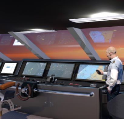
3 RH Marine Segments Special vessels Defence, Safety & Security Yachts & Refits Cruises & Ferries

4 RH Marine Rhodium family

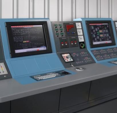
5 The transformer
6 COMMON MODE REDUCTION LF

7 Common mode attenuation Differential mode and common mode currents source Load
8 Common mode attenuation Common mode attenuation at low frequencies Differential mode current Common mode current Magnetic flux Transformer As long as proper shape transformer core is chosen!!!
9 HARMONIC REDUCTION
10 Reduction of harmonics, multiples of three 1,50 1,00 0,50 0,00-0,50-1,00-1,50 1,50 1,00 0,50 0,00-0,50-1,00-1, L3 L2 L1 L1 L3 h5 h2 h3 h4 h6 L3 L2 h2 h3 h4 h5 h6 L2 L1 h2 h3 h4 h5 h6
11 3-phase Voltage Reduction of harmonics n*3 Coil --> terminal voltages star winding W V U Load 2,00 1,50 1,00 0,50 WU W U V 0,00-0,50-1, U W -1,50-2,00
12 Reduction of harmonics n*3 Rectifier Generated harmonics pulse 6*n ± 1: X X X X X X X X X X X X X X X X 12 pulse 12*n ± 1 X X X X X X X X 18 pulse 18*n ± 1 X X X X 24 pulse 24*n ± 1 X X X X 48 pulse 48*n ± 1 X X
13 COMMON MODE REDUCTION HF


14 Common mode attenuation HF Common mode attenuation at high frequencies P S Transformer Ucm


15 Common mode attenuation HF Common mode attenuation at high frequencies P S Transformer Ucm

16 Common mode attenuation example


17 att (db) Common mode attenuation Transformer attenuation 70,0 60,0 50,0 40,0 30,0 20,0 10,0 0,0 0, , , , f (MHz)
18 Common mode attenuation Primary Secondary U cm
19 FAULT CURRENT REDUCTION

20 Reduction of fault currents in IT power grids IT power grid TN power grid Protection against electrocution Continuity of supply


21 Reduction of fault currents in IT power grids System: 440 V, 60 Hz, IT (parasitic) capacitance to earth I_earth fault Consequence 100 nf 30 ma Electrocution µf A Fire risk (Parasitic) Capacitances to earth in an installation: Cables µf per km Motors µf, depending on size Generators µf, depending on size EMI filters µf (!), depending on rating
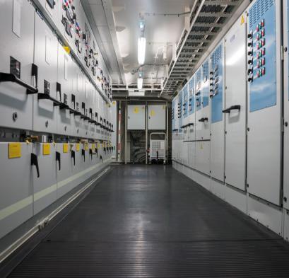
22 REDUCTION OF SHORT CIRCUIT POWER

23 Reduction of short circuit powers Total installed power: 95,000 kw Thrusters: 12 x 6050 kw non-retractable, fixed pitch, variable speed
24 Reduction of short circuit powers 240kVA
25 Reduction of short circuit powers 4 MVA (6%) 240 kva (4%) Isc 87 ka 15 ka
26 Reduction of short circuit powers National Fire Protection Association NFPA 70E Standard for Electrical Safety in the Workplace Table 130.7(C)(15)(A)(b) Arc-Flash Hazard PPE Categories for Alternating Current (ac) Systems The arc flash boundary shall be the distance at which the incident energy equals 5 J/cm2 (1.2 cal/cm2).
27 Equipment Reduction of short circuit powers Panelboards or other equipment rated 240 V and below Parameters: Maximum of 25 ka short-circuit current available; maximum of 0.03 sec (2 cycles) fault clearing time; working distance 455 mm (18 in.) Panelboards or other equipment rated >240 V and up to 600 V Parameters: Maximum of 25 ka short-circuit current available; maximum of 0.03 sec (2 cycles) fault clearing time; working distance 455 mm (18 in.) 600-V class motor control centers (MCCs) Parameters: Maximum of 65 ka short-circuit current available; maximum of 0.03 sec (2 cycles) fault clearing time; working distance 455 mm (18 in.) 600-V class motor control centers (MCCs) Parameters: Maximum of 42 ka short-circuit current available; maximum of 0.33 sec (20 cycles) fault clearing time; working distance 455 mm (18 in.) Arc Flash PPE Category Arc-Flash Boundary mm mm m m

28 Reduction of short circuit powers
29 RISKS TRANSIENTS
30 Damage caused by transients


31 Damage caused by transients Transformer 4 1. Inter-layer fault between layer 2 and 3 Earth screen Layer: Transformer 8 2. Earth fault, developing into inter-turn fault in layer 1 3. Inter-layer fault between layer 2 and 3 Transformer 5 4. Inter-turn fault in layer 1 Phase shifting winding Delta winding (4) (2) (1), (3)

?")
32 Damage caused by transients High voltage peaks? No: Highest peak measured was 17 kv. For a 11 kv transformer winding this is not high at all. High rate of rise (du/dt)? Yes: du/dt measured as high as 130 kv/μs. This is extremely high.

33 Damage caused by transients

34 Damage caused by transients

35 Damage caused by transients
36 RISKS TEMPERATURE

37 Cooling aspects

38 Cooling aspects
39 Cooling aspects Space requirements Heating by harmonics Internal circulating currents
40 THANK YOU FOR YOU ATTENTION
First Draft Language
 110.16 First Draft Language (B) Service Equipment. In addition to the requirements in (A), service equipment shall contain the following information: (1) Nominal system voltage (2) Arc flash boundary (3)
{40C54206-A3BA D8-8D8CF }
 Informative Annex D Incident Energy and Arc Flash Boundary Calculation Methods This informative annex is not a part of the requirements of this NFPA document but is included for informational purposes
ARC FLASH PPE GUIDELINES FOR INDUSTRIAL POWER SYSTEMS
 The Electrical Power Engineers Qual-Tech Engineers, Inc. 201 Johnson Road Building #1 Suite 203 Houston, PA 15342-1300 Phone 724-873-9275 Fax 724-873-8910 www.qualtecheng.com ARC FLASH PPE GUIDELINES FOR
Steve Kovach District Sales Engineer
 Steve Kovach District Sales Engineer 630-740-7463 Steveekovach@Eaton.com Institute of Electrical and Electronics Engineers American Society of Safety Engineers 1 Electrical Hazards Electrical Hazards Shock
Understanding and Optimizing Electromagnetic Compatibility in Switchmode Power Supplies
 Understanding and Optimizing Electromagnetic Compatibility in Switchmode Power Supplies 1 Definitions EMI = Electro Magnetic Interference EMC = Electro Magnetic Compatibility (No EMI) Three Components
Arc Flash Analysis and Documentation SOP
 Arc Flash Analysis and Documentation SOP I. Purpose.... 2 II. Roles & Responsibilities.... 2 A. Facilities Maintenance (FM).... 2 B. Zone Supervisors/ Shop Foremen... 2 C. PMCS & CPC... 2 III. Procedures...
Introduction EMC. Filter parameters. Definition of EMC / EMI. X-Capacitor. Sources of EMI. Coupling mechanism. Y-Capacitor.
 Introduction to EMC Schurter has over 75 years experience in the electronics and electrical industries, developing and manufacturing components that ensure a clean and safe supply of power. Schurter provides
Electrical Arc Hazards
 Arc Flash Analysis 1996-2009 ETAP Workshop Operation Notes Technology, 1996-2009 Inc. Operation Workshop Technology, Notes: Arc Inc. Flash Analysis Slide 1 Electrical Arc Hazards Electrical Arcs can occur
6. du/dt-effects in inverter-fed machines
 6. du/dt-effects in inverter-fed machines Source: A. Mütze, PhD Thesis, TU Darmstadt 6/1 6. du/dt-effects in inverter-fed machines 6.1 Voltage wave reflections at motor terminals Source: A. Mütze, PhD
Arc Flash and NFPA 70E
 Arc Flash and NFPA 70E Presented by: J.D. Kyle Safe Work Practices Wearing Proper PPE? OSHA 1910.333 (a) (1) not to work hot or live except : 1. De energizing introduces additional or increased hazards
Alternative Coupling Method for Immunity Testing of Power Grid Protection Equipment
 Alternative Coupling Method for Immunity Testing of Power Grid Protection Equipment Christian Suttner*, Stefan Tenbohlen Institute of Power Transmission and High Voltage Technology (IEH), University of
High precision measurement system for current and voltage IHC-A/B-RM01/03
 Measurement Offset-free and low-noise 16 bit data acquisition system ISA-ASIC Internal sample rate 3,500 Hz Communication Standard RS232- or RS485 interface Advantages Direct measurement on the bus bar
REDUCING ARC FLASH HAZARD BY REMOTE SWITCHING
 The Electrical Power Engineers Qual-Tech Engineers, Inc. 21 Johnson Road Building #1 Suite 23 Houston, PA 15342-13 Phone 724-873-9275 Fax 724-873-891 www.qualtecheng.com REDUCING ARC FLASH HAZARD BY REMOTE
AN EXAMPLE OF A STANDARD ARC FLASH PPE LABELING STRATEGY
 The Electrical Power Engineers Qual-Tech Engineers, Inc. 201 Johnson Road Building #1 Suite 203 Houston, PA 15342-1300 Phone 724-873-9275 Fax 724-873-8910 www.qualtecheng.com AN EXAMPLE OF A STANDARD ARC
3-Phase Transformers. Author: Sergey Dubatov. belfuse.com/signal
 3-Phase Transformers Author: Sergey Dubatov 2 A transformer is an electrical device which, by electromagnetic induction, transforms power between circuits at the same frequency, usually changing the values
Code No: R Set No. 1
 Code No: R05310204 Set No. 1 III B.Tech I Semester Regular Examinations, November 2007 ELECTRICAL MACHINES-III (Electrical & Electronic Engineering) Time: 3 hours Max Marks: 80 Answer any FIVE Questions
AN EXAMPLE OF A STANDARD ARC FLASH PPE LABELING STRATEGY
 The Electrical Power Engineers Qual-Tech Engineers, Inc. 201 Johnson Road Building #1 Suite 203 Houston, PA 15342-1300 Phone 724-873-9275 Fax 724-873-8910 www.qualtecheng.com AN EXAMPLE OF A STANDARD ARC
R10. IV B.Tech I Semester Regular/Supplementary Examinations, Nov/Dec SWITCH GEAR AND PROTECTION. (Electrical and Electronics Engineering)
") R10 Set No. 1 Code No: R41023 1. a) Explain how arc is initiated and sustained in a circuit breaker when the CB controls separates. b) The following data refers to a 3-phase, 50 Hz generator: emf between
R10 Set No. 1 Code No: R41023 1. a) Explain how arc is initiated and sustained in a circuit breaker when the CB controls separates. b) The following data refers to a 3-phase, 50 Hz generator: emf between
Discipline Electrical Testing Issue Date Certificate Number T-2837 Valid Until Last Amended on - Page 1 of 6 LOCATION 1
 Post: Last Amended on - Page 1 of 6 LOCATION 1 I. TRANSFORMERS AND REACTORS 1. 500 MVA, 765 kv 500 MVA, 400 kv Ratio & Polarity Check Magnetic Balance & Magnetizing Current Measurement at Low Voltage Vector
Realisation of the galvanic isolation in customer-end DC to AC inverters for the LVDC distribution
 Realisation of the galvanic isolation in customer-end DC to AC inverters for the LVDC distribution Background: The electric distribution network in Finland has normally voltage levels of 20 kv and 400
thepower to protect the power to protect i-gard LITERATURE Low and medium voltage
 thepower to protect i-gard LITERATURE Low and medium voltage distribution systems Arc Flash Hazards and High Resistance Grounding Grounding of Standby and Emergency Power Systems Neutral Grounding Resistors
MV network design & devices selection EXERCISE BOOK
 MV network design & devices selection EXERCISE BOOK EXERCISES 01 - MV substation architectures 02 - MV substation architectures 03 - Industrial C13-200 MV substation 04 - Max. distance between surge arrester
2018 Consultant s Handbook Division 26 Electrical ARC Flash Hazard Analysis
 1 Summary 1.1 Provide a complete Arc Flash Hazard Analysis for the project indicated in the accompanying RFP. The Analysis may be performed: independent of the construction project in concert with the
ADVANCES IN INDUSTRIAL SUBSTATION DESIGN USING THREE WINDING POWER TRANSFORMERS
 ADVANCES IN INDUSTRIAL SUBSTATION DESIGN USING TREE WINDING POWER TRANSFORMERS Copyright Material IEEE Paper No. PCIC-2008-XX Doug Brooks P.Eng Don Morency P.Eng. Pascal Tang P.Eng Senior Member, IEEE
DESIGN STANDARD DS 29
 Assets Delivery Group Engineering DESIGN STANDARD DS 29 VERSION 1 REVISION 2 MAY 2018 FOREWORD The intent of Design Standards is to specify requirements that assure effective design and delivery of fit
EMI Filter Safety. Herbert Blum Product Manager EMC
 Herbert Blum Product Manager EMC Level in dbµv EMI Filter Safety > Application with high EMI noise over the standard limits 80 70 60 EN 55011 Voltage on Mains QP Class B 50 EN 55011 Voltage on Mains AV
, ,54 A
 AEB5EN2 Ground fault Example Power line 22 kv has the partial capacity to the ground 4,3.0 F/km. Decide whether ground fault currents compensation is required if the line length is 30 km. We calculate
Selection of PPE Practical experience of different arc assessment methods and their comparison
 Selection of PPE Practical experience of different arc assessment methods and their comparison Dr.-Ing. Thomas Jordan Markus Kauschke Slide 1 ICOLIM 2017 Selection of Arc Flash PPE BSD Electrical Safety
Electrical Description
 History of this Document Rev. no.: Date: Description of change 0 First edition 2 2003-10-08 Section 3: The rated power of the transformer can be increased by 40% if they are equipped with 6 fans for forced
Conventional Paper-II-2011 Part-1A
 Conventional Paper-II-2011 Part-1A 1(a) (b) (c) (d) (e) (f) (g) (h) The purpose of providing dummy coils in the armature of a DC machine is to: (A) Increase voltage induced (B) Decrease the armature resistance
SECTION OVERCURRENT PROTECTIVE DEVICE COORDINATION STUDY
 PART 1 - GENERAL 1.1 DESCRIPTION SECTION 26 05 73 OVERCURRENT PROTECTIVE DEVICE COORDINATION STUDY SPEC WRITER NOTE: Delete between // -- // if not applicable to project. Also, delete any other item or
Installation Filters. High Performance. Installation Filters. Product Range. Contact T: +44 (0) F: +44 (0) E:
 F: +44 (0) E:") Installation Filters /12 Installation Filters High Performance Installation Filters This information is for guidance only. 212 MPE Limited Introduction MPE Limited is a world leading manufacturer of high
Installation Filters /12 Installation Filters High Performance Installation Filters This information is for guidance only. 212 MPE Limited Introduction MPE Limited is a world leading manufacturer of high
AC/DC Power Supply Series APPLICATION NOTE
 ZMS100 AC/DC Power Supply Series APPLICATION NOTE ZMS100 Application Notes Issue 3 Document Number 260160 Page 1 of 15 Contents Contents... 2 1. INPUT... 3 AC INPUT LINE REQUIREMENTS... 3 2. DC OUTPUT...
Coupling modes. Véronique Beauvois, Ir Copyright 2015 Véronique Beauvois, ULg
 Coupling modes Véronique Beauvois, Ir. 2015-2016 General problem in EMC = a trilogy Parameters Amplitude Spectrum Source (disturbing) propagation Coupling modes Victim (disturbed) lightning electrostatic
SECTION SHORT CIRCUIT, COMPONENT PROTECTION, FLASH HAZARD AND SELECTIVE COORDINATION STUDY
 SECTION 16075 - SHORT CIRCUIT, COMPONENT PROTECTION, FLASH HAZARD AND SELECTIVE COORDINATION STUDY PART 1 GENERAL 1.1 SUMMARY A. Section Includes: 1. Provide a short-circuit, component protection, flash
50W Constant Current (700mA) Dimming LED Driver
 Dimming LED Driver") 50W Constant Current (700mA) Dimming LED Driver IZC070-050A-9267C-SA Product Overview The IZC070-050A-9267C-SA operate from a 90-305 Vac input range. This unit will provide up to a 700mA of output current
50W Constant Current (700mA) Dimming LED Driver IZC070-050A-9267C-SA Product Overview The IZC070-050A-9267C-SA operate from a 90-305 Vac input range. This unit will provide up to a 700mA of output current
Vacon Baltic Days Tallinn, Estonia
 Vacon Baltic Days 22.-23.9.2011 Tallinn, Estonia Vacon Technology Yrjö Karvonen Technical Account Manager Frequency converter Why to use Applications Energy saving Easy to control (ma, V, digital I/O,
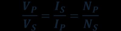
TRANSFORMERS PART A. 2. What is the turns ratio and transformer ratio of transformer? Turns ratio = N2/ N1 Transformer = E2/E1 = I1/ I2 =K
 UNIT II TRANSFORMERS PART A 1. Define a transformer? A transformer is a static device which changes the alternating voltage from one level to another. 2. What is the turns ratio and transformer ratio of
86 chapter 2 Transformers
 86 chapter 2 Transformers Wb 1.2x10 3 0 1/60 2/60 3/60 4/60 5/60 6/60 t (sec) 1.2x10 3 FIGURE P2.2 2.3 A single-phase transformer has 800 turns on the primary winding and 400 turns on the secondary winding.
Flexible AC current probes
 Flexible AC current probes Making use of the principle of Rogowski coils, the MiniFLEX models are flexible sensors offering a wide dynamic range for measuring AC intensities and viewing high-speed current
The practicalities of measuring fast switching currents in power electronics using Rogowski probes
 The practicalities of measuring fast switching currents in power electronics using Rogowski probes Dr Chris Hewson Director, PEM Ltd Booth No. 418 About PEM Ltd Power Electronic Measurements Ltd (PEM)
Electromagnetic Compatibility
 Electromagnetic Compatibility Introduction to EMC International Standards Measurement Setups Emissions Applications for Switch-Mode Power Supplies Filters 1 What is EMC? A system is electromagnetic compatible
ABB AG - EPDS. I S -limiter The worldʼs fastest limiting and switching device
 ABB AG - EPDS The worldʼs fastest limiting and switching device Agenda The world s fastest limiting and switching device Customers Function: Insert-holder with insert Comparison: I S -limiter Circuit-breaker
Max. Output Power. Efficiency (1) 110Vac 220Vac
 110Vac 220Vac") LED Driver EUV150SxxxST 20100531 H Features Ultra High (Up to ) High Power Factor (0.99 Typical) 150 W Continuous Power Lightning Protection AllRound Protection: OVP, OCP, SCP, OTP Waterproof (IP67) Comply
LED Driver EUV150SxxxST 20100531 H Features Ultra High (Up to ) High Power Factor (0.99 Typical) 150 W Continuous Power Lightning Protection AllRound Protection: OVP, OCP, SCP, OTP Waterproof (IP67) Comply
Webinar: An Effective Arc Flash Safety Program
 Webinar: An Effective Arc Flash Safety Program Daleep Mohla September 10 th, 2015: 2pm ET Agenda Arc Flash Defined and Quantified NFPA 70E / CSA Z 462 - Recent Updates What is the ANSI Z10 Hierarchy of
Applications & Cases. EPCOS AG A TDK Group Company Edition
 Applications & Cases Reference Firs EPCOS AG A TDK Group Company Edition 2018 www.epcos.com 1 / 11 egrated solution for inverters to be used in e-mobility powertrains and industrial applications. The design
Arc Flash Hazard and Mitigation 2 nd Workshop on Power Converters for Particle Accelerators June 14 16, 2010
 Arc Flash Hazard and Mitigation 2 nd Workshop on Power Converters for Particle Accelerators June 14 16, 2010 Paul Bellomo June 14-16, 2010 2nd Workshop on Power Converters for Particle Accelerators - Arc
HIGH VOLTAGE ENGINEERING(FEEE6402) LECTURER-24
 LECTURER-24") LECTURER-24 GENERATION OF HIGH ALTERNATING VOLTAGES When test voltage requirements are less than about 300kV, a single transformer can be used for test purposes. The impedance of the transformer should
LECTURER-24 GENERATION OF HIGH ALTERNATING VOLTAGES When test voltage requirements are less than about 300kV, a single transformer can be used for test purposes. The impedance of the transformer should
Arc Flash Study Principles & Procedures for below 15 kv AC Systems. Xuan Wu, Dennis Hoffman, Ronald Wellman, and Manish Thakur
 Arc Flash Study Principles & Procedures for below 15 kv AC Systems Xuan Wu, Dennis Hoffman, Ronald Wellman, and Manish Thakur Agenda Arc Flash Study Purposes Introduction of Arc Flash Arc Flash Risk Locations
Methods for Reducing Emissions from Switching Power Circuits. A. McDowell, C. Zhu and T. Hubing
 Methods for Reducing Emissions from Switching Power Circuits A. McDowell, C. Zhu and T. Hubing 1 Objective To reduce radiated emissions and other forms of interference from power inverter circuits, by
Contents Summary Application. 2 Electrical Specifications...3 Products and Accessories... 4 Products Accessories Typical Mechanical
 Flexible Current Probe CP9000(S/L) Shenzhen Zhiyong Electronic Co., Ltd www.cybertek.cn Contents Summary.... 2 Application. 2 Electrical Specifications...3 Products and Accessories... 4 Products.....4
Power electronic converters in power systems. SINTEF Energy Research
 Power electronic converters in power systems 1 Typical application of grid connected converters Active rectifier (sinusoidal line current, bi-directional power flow, adjustable power factor) Grid interface
NFPA-70E. Electrical Safety in the Workplace. Standard for Edition
 NFPA-70E Standard for Electrical Safety in the Workplace 2015 Edition NFPA-70E 90.1 Purpose. The purpose of this standard is to provide a practical safe working area for employees relative to the hazards
NOTICE ER Roland Flood Pumping Station Arc Flash Study
 NOTICE This document contains the expression of the professional opinion of SNC-Lavalin Inc. (SLI) as to the matters set out herein, using its professional judgment and reasonable care. It is to be read
Cable Solutions for Servo and Variable Frequency Drives (VFD)
") Cable Solutions for Servo and Variable Frequency Drives (VFD) Electric drive systems with continuous torque and speed control are widespread today. They allow an optimal adjustment of the drive with respect
Cable Solutions for Servo and Variable Frequency Drives (VFD) Electric drive systems with continuous torque and speed control are widespread today. They allow an optimal adjustment of the drive with respect
Typical Efficiency (1) 350 ma 90 ~ 305 Vac 428 Vdc 150 W 93.5% EUC-150S035DT
 350 ma 90 ~ 305 Vac 428 Vdc 150 W 93.5% EUC-150S035DT") Features Ultra High Efficiency (Up to 93.5%) Active Power Factor Correction (0.99 Typical) Constant Current Output Lightning Protection AllRound Protection: SCP, OTP, OVP Waterproof (IP67) Comply With
Features Ultra High Efficiency (Up to 93.5%) Active Power Factor Correction (0.99 Typical) Constant Current Output Lightning Protection AllRound Protection: SCP, OTP, OVP Waterproof (IP67) Comply With
Caution - leakage currents! Leakage currents in fault-current protected environments
 Caution - leakage currents! Leakage currents in fault-current protected environments Herbert Blum Product Manager EMC > General situation > Leakage current vs. fault current > Leakage currents from frequency
ELECTRICAL POWER TRANSMISSION TRAINER
 ELECTRICAL POWER TRANSMISSION TRAINER ELECTRICAL POWER TRANSMISSION TRAINER This training system has been designed to provide the students with a fully comprehensive knowledge in Electrical Power Engineering
SAM Listed LED Optimized Drivers. Environmental. Electrical Specifications at 25 O C E Output Current. Voltage Accuracy
 SAM Listed Model: LD12W - LD200W Series Environmental Strip Lighting Drive Mode: Constant Voltage Technology: PFC Off-Line Switch Mode Output Power: 12-200W Max. Output Voltages: 12VDC or 24VDC Optional
Phase Shifting Transformers. Presented by
 Phase Shifting Transformers Presented by Phase Shifting Transformers (PST s) (a.k.a. Phase Angle Regulators) VS φ S P V V S = X L L X L sin( φ φ ) L S VL φ L PST s are power flow control devices between
THREE PHASE PAD MOUNTED DISTRIBUTION TRANSFORMER ARC FLASH TESTING JUNE 23, 2009 FERRAZ SHAWMUT HIGH POWER LABORATORY NEWBURYPORT, MA
 THREE PHASE PAD MOUNTED DISTRIBUTION TRANSFORMER ARC FLASH TESTING JUNE 23, 2009 FERRAZ SHAWMUT HIGH POWER LABORATORY NEWBURYPORT, MA Witnessed by: Jim Phillips, PE, Consultant Craig DeRouen, ERMCO Director
EARTH FAULT PROTECTION VIS-A-VIS GENERATOR GROUNDING SYSTEM
 EARTH FAULT PROTECTION VIS-A-VIS GENERATOR GROUNDING SYSTEM BY MR. H. C. MEHTA AT 1 ST INDIA DOBLE PROTECTION AND AUTOMATION CONFERENCE, NOV 2008 POWER-LINKER Wisdom is not Virtue but Necessity hcmehta@powerlinker.org
Power Electronics. Exercise: Circuit Feedback
 Lehrstuhl für Elektrische Antriebssysteme und Leistungselektronik Technische Universität München Prof Dr-Ing Ralph Kennel Aricsstr 21 Email: eat@eitumde Tel: +49 (0)89 289-28358 D-80333 München Internet:
NATIONAL ELECTRIC SAFETY CODE 2012 EDITION
 NATIONAL ELECTRIC SAFETY CODE (ANSI C2 / NESC) 2012 EDITION Jim Tomaseski IBEW Director of Safety and Health EEI Safety and Health Committee Conference NESC 2012 IMPORTANT DATES SEPTEMBER 1, 2009 - Preprint
STRAY FLUX AND ITS INFLUENCE ON PROTECTION RELAYS
 1 STRAY FLUX AND ITS INFLUENCE ON PROTECTION RELAYS Z. GAJIĆ S. HOLST D. BONMANN D. BAARS ABB AB, SA Products ABB AB, SA Products ABB AG, Transformers ELEQ bv Sweden Sweden Germany Netherlands zoran.gajic@se.abb.com
About the High-Frequency Interferences produced in Systems including PWM and AC Motors
 About the High-Frequency Interferences produced in Systems including PWM and AC Motors ELEONORA DARIE Electrotechnical Department Technical University of Civil Engineering B-dul Pache Protopopescu 66,
EMC Refresh Presented by Sylvain LE BRAS Würth Elektronik eisos France
 EMC Refresh Presented by Sylvain LE BRAS Würth Elektronik eisos France Agenda WHAT IS EMC? INDUCTIVE EMC SOLUTIONS BASICS INSERTION LOSS OF INDUCTIVE SOLUTIONS CAPACITIVE EMC SOLUTIONS BASICS INSERTION
ARC FLASH HAZARD ANALYSIS AND MITIGATION
 ARC FLASH HAZARD ANALYSIS AND MITIGATION J.C. Das IEEE PRESS SERIES 0N POWER ENGINEERING Mohamed E. El-Hawary, Series Editor IEEE IEEE PRESS WILEY A JOHN WILEY & SONS, INC., PUBLICATION CONTENTS Foreword
DEIF A/S. Insulation monitor. Type SIM-Q/SIM-Q LF
 / LF Insulation monitor Monitoring of insulation resistance on ungrounded AC networks (IT network) Working voltage up to 69V AC, withstands up to V DC Measuring range...kω or 1...MΩ Working frequency down
Beskrivelse av simuleringsmodell ==> Description of simulation model
 Infrastruktur Elkraft / Energy Side / Page: 1 av / of 6 Beskrivelse av simuleringsmodell ==> Description of simulation model General The modelled system consists of one rotary converter (synchronous-synchronous
Arc Flash Calculation Methods
 Arc Flash Calculation Methods Course No: E04-033 Credit: 4 PDH Velimir Lackovic, Char. Eng. Continuing Education and Development, Inc. 9 Greyridge Farm Court Stony Point, NY 10980 P: (877) 322-5800 F:
AC Motor Drives EMC Standard Installation Guide EMC Compliance Practice
 http://www.delta.com.tw/industrialautomation/ AC Motor Drives EMC Standard Installation Guide EMC Compliance Practice i Preface When an AC motor drive is installed in a noisy environment, radiated and/or
75W Constant Current (700mA) LED Driver
 LED Driver") 75W Constant Current (700mA) LED Driver IZC070-075A-9267C-SA Product Overview The IZC070-075A-9267C-SA operates from a 90-305 Vac input range. This unit will provide up to 700mA of output current and a
75W Constant Current (700mA) LED Driver IZC070-075A-9267C-SA Product Overview The IZC070-075A-9267C-SA operates from a 90-305 Vac input range. This unit will provide up to 700mA of output current and a
Power Supplies in Accelerators
 Power Supplies in Accelerators Neil Marks, ASTeC, Cockcroft Institute, Daresbury, Warrington WA4 4AD, neil.marks@stfc.ac.uk Tel: (44) (0)1925 603191 Fax: (44) (0)1925 603192 Contents 1. Basic elements
MINING EARTH LEAKAGE PROTECTION WITH VARIABLE SPEED DRIVES
 MINING EARTH LEAKAGE PROTECTION WITH VARIABLE SPEED DRIVES White Paper Tim Wylie, Ampcontrol s Chief Technology Officer discusses the impact of Variable Speed Drives (VSDs) on earth fault limited networks.
One-day Conference 18 March Power Supply, EMC and Signalling, in Railway Systems
 One-day Conference 18 March 2017 Power Supply, EMC and Signalling, in Railway Systems EMC Management and Related Technical Aspects in Railway Systems By Dr Peter S W LEUNG http://www.ee.cityu.edu.hk/~pswleung/
Exercises of resistors 1. Calculate the resistance of a 10 m long Copper wire with diameter d = 1.0 mm.
 Exercises of resistors 1. Calculate the resistance of a 10 m long Copper wire with diameter d = 1.0 mm. 2. Calculate the resistances of following equipment: using 220V AC a) a 1000 W electric heater b)
Chapter 5 Electromagnetic interference in flash lamp pumped laser systems
 Chapter 5 Electromagnetic interference in flash lamp pumped laser systems This chapter presents the analysis and measurements of radiated near and far fields, and conducted emissions due to interconnects
TEST SUMMARY Seite 2 von 27. Prüfbericht - Nr.: Test Report No HARMONICS ON AC MAINS RESULT: Passed
 17035561 001 Seite 2 von 27 Page 2 of 27 TEST SUMMARY 5.1.1 HARMONICS ON AC MAINS RESULT: Passed 5.1.2 VOLTAGE FLUCTUATIONS ON AC MAINS RESULT: Passed 5.1.3 TERMINAL CONTINUOUS DISTURBANCE VOLTAGE AT RESULT:
Max. Output Power. Efficiency (1) 110Vac 220Vac
 110Vac 220Vac") Features High (Up to 92%) Active Power Factor Correction (0.99 Typical) Constant Current Lightning Protection AllRound Protection: OVP, SCP, OTP Waterproof (IP67) Comply With UL8750 & EN61347 Safety Regulations
Features High (Up to 92%) Active Power Factor Correction (0.99 Typical) Constant Current Lightning Protection AllRound Protection: OVP, SCP, OTP Waterproof (IP67) Comply With UL8750 & EN61347 Safety Regulations
BE Semester- VI (Electrical Engineering) Question Bank (E 605 ELECTRICAL POWER SYSTEM - II) Y - Y transformer : 300 MVA, 33Y / 220Y kv, X = 15 %
 Question Bank (E 605 ELECTRICAL POWER SYSTEM - II) Y - Y transformer : 300 MVA, 33Y / 220Y kv, X = 15 %") BE Semester- V (Electrical Engineering) Question Bank (E 605 ELECTRCAL POWER SYSTEM - ) All questions carry equal marks (10 marks) Q.1 Explain per unit system in context with three-phase power system and
BE Semester- V (Electrical Engineering) Question Bank (E 605 ELECTRCAL POWER SYSTEM - ) All questions carry equal marks (10 marks) Q.1 Explain per unit system in context with three-phase power system and
IV/IV B.Tech (Regular) DEGREE EXAMINATION. Electrical &Electronics Engineering
 DEGREE EXAMINATION. Electrical &Electronics Engineering") Hall Ticket Number: 14EE704 November, 2017 Seventh Semester Time: Three Hours Answer Question No.1 compulsorily. Answer ONE question from each unit. IV/IV B.Tech (Regular) DEGREE EXAMINATION Electrical
Hall Ticket Number: 14EE704 November, 2017 Seventh Semester Time: Three Hours Answer Question No.1 compulsorily. Answer ONE question from each unit. IV/IV B.Tech (Regular) DEGREE EXAMINATION Electrical
3. What is hysteresis loss? Also mention a method to minimize the loss. (N-11, N-12)
") DHANALAKSHMI COLLEGE OF ENGINEERING, CHENNAI DEPARTMENT OF ELECTRICAL AND ELECTRONICS ENGINEERING EE 6401 ELECTRICAL MACHINES I UNIT I : MAGNETIC CIRCUITS AND MAGNETIC MATERIALS Part A (2 Marks) 1. List
DHANALAKSHMI COLLEGE OF ENGINEERING, CHENNAI DEPARTMENT OF ELECTRICAL AND ELECTRONICS ENGINEERING EE 6401 ELECTRICAL MACHINES I UNIT I : MAGNETIC CIRCUITS AND MAGNETIC MATERIALS Part A (2 Marks) 1. List
Design a Power System Simulator Model and Implement the Generator and Motor Controlling
 Design a Power System Simulator Model and Implement the Generator and Motor Controlling G.U De Silva, G.B Alahendra, A.C.P Aluthgama, P.G.L Arachchi Supervised by: Prof. J Rohan Lucas, Eng. J. Karunanayake
DEPARTMENT OF ELECTRICAL AND ELECTRONICS ENGINEERING QUESTION BANK SUBJECT CODE & NAME : EE 1402 HIGH VOLTAGE ENGINEERING UNIT I
 DEPARTMENT OF ELECTRICAL AND ELECTRONICS ENGINEERING QUESTION BANK SUBJECT CODE & NAME : EE 1402 HIGH VOLTAGE ENGINEERING YEAR / SEM : IV / VII UNIT I OVER VOLTAGES IN ELECTRICAL POWER SYSTEMS 1. What
2015 NFPA 70E. SESHA 2015 ARIZONA MINI CONFERENCE December 10, 2015 Intel Corporation
 2015 NFPA 70E SESHA 2015 ARIZONA MINI CONFERENCE December 10, 2015 Intel Corporation Introduction Jeffrey A. Pugh, P.E. Pugh Engineering LLC Bachelor of Science Degrees in Electrical Engineering and Computer
Distribution Transformer Random Transient Suppression using Diode Bridge T-type LC Reactor
 Distribution Transformer Random Transient Suppression using Diode Bridge T-type LC Reactor Leong Bee Keoh 1, Mohd Wazir Mustafa 1, Sazali P. Abdul Karim 2, 1 University of Technology Malaysia, Power Department,
Design Approaches for Hospital Distribution Systems With Considerations for Future Expansion, Operator Safety, and Cost
 Design Approaches for Hospital Distribution Systems With Considerations for Future Expansion, Operator Safety, and Cost Adam T. Powell, PE President Emerald Engineering, Inc. Jeffrey L. Small, Sr. Senior
World-Class Accuracy & Measurement Range (40 Conventional Models)
") AC/DC CURRENT SENSOR CT6904 Ultra-High Performance AC/DC Current Sensor World-Class Accuracy & Measurement Range (40 Conventional Models) 500 A (rms) Rated for measurement of large currents 4 MHz (±3 db)
AC/DC CURRENT SENSOR CT6904 Ultra-High Performance AC/DC Current Sensor World-Class Accuracy & Measurement Range (40 Conventional Models) 500 A (rms) Rated for measurement of large currents 4 MHz (±3 db)
Key factors to maintaining arc flash safety
 APPLICATI TE Key factors to maintaining arc flash safety Arc flash and blast When an arc fault occurs, the result is a massive electrical explosion. The light and heat emitted by the explosion is known
Figure Derive the transient response of RLC series circuit with sinusoidal input. [15]
![Figure Derive the transient response of RLC series circuit with sinusoidal input. [15]](/thumbs/84/91046828.jpg "Figure Derive the transient response of RLC series circuit with sinusoidal input. [15]") COURTESY IARE Code No: R09220205 R09 SET-1 B.Tech II Year - II Semester Examinations, December-2011 / January-2012 NETWORK THEORY (ELECTRICAL AND ELECTRONICS ENGINEERING) Time: 3 hours Max. Marks: 80 Answer
COURTESY IARE Code No: R09220205 R09 SET-1 B.Tech II Year - II Semester Examinations, December-2011 / January-2012 NETWORK THEORY (ELECTRICAL AND ELECTRONICS ENGINEERING) Time: 3 hours Max. Marks: 80 Answer
Upgrading Your Electrical Distribution System To Resistance Grounding
 Upgrading Your Electrical Distribution System To Resistance Grounding The term grounding is commonly used in the electrical industry to mean both equipment grounding and system grounding. Equipment grounding
ELECTRICIAN S THEORY EXAMINATION 17 November 2012 QUESTION AND ANSWER BOOKLET
 Candidate Code No. ET43 For Board Use Only Result Date Int Result Date Int ELECTRICIAN S THEORY EXAMINATION 17 November 2012 QUESTION AND ANSWER BOOKLET INSTRUCTIONS READ CAREFULLY Time Allowed: Three
EMI AND BEL MAGNETIC ICM
 EMI AND BEL MAGNETIC ICM ABSTRACT Electromagnetic interference (EMI) in a local area network (LAN) system is a common problem that every LAN system designer faces, and it is a growing problem because the
Simultaneous AC-DC Transmission Scheme Under Unbalanced Load Condition
 Simultaneous AC-DC Transmission Scheme Under Unbalanced Load Condition M. A. Hasan, Priyanshu Raj, Krritika R Patel, Tara Swaraj, Ayush Ansuman Department of Electrical and Electronics Birla Institute
Differential Protection with REF 542plus Feeder Terminal
 Differential Protection with REF 542plus Application and Setting Guide kansikuva_bw 1MRS 756281 Issued: 09.01.2007 Version: A Differential Protection with REF 542plus Application and Setting Guide Contents:
Dielectric response and partial discharge measurements on stator insulation at varied low frequency. Nathaniel Taylor
 Dielectric response and partial discharge measurements on stator insulation at varied low frequency Nathaniel Taylor Rotating Electrical Machines : The Stator and its Windings turbo-generator motor hydro-generator
CHAPTER 5 POWER QUALITY IMPROVEMENT BY USING POWER ACTIVE FILTERS
 86 CHAPTER 5 POWER QUALITY IMPROVEMENT BY USING POWER ACTIVE FILTERS 5.1 POWER QUALITY IMPROVEMENT This chapter deals with the harmonic elimination in Power System by adopting various methods. Due to the
MEDIUM VOLTAGE PRODUCT. PARAMETERS GUIDE How to specify the indoor instrument transformers correctly
 MEDIUM VOLTAGE PRODUCT PARAMETERS GUIDE How to specify the indoor instrument transformers correctly The range of electric values in the power supply systems is very extensive. This is why it is necessary
ULTRA-K Series 600K - he
 5 kva 500 kva ULTRA-K Series 600K - he High Efficiency K-Rated Power Conditioning Transformers Designed to be used with linear or non-linear loads. Applications: Audio / Video Recording Equipment IT Systems