Notes on Rebuilding an SB-220 Linear Amplifier
|
|
|
- Brent Page
- 6 years ago
- Views:
Transcription

1 Notes on Rebuilding an SB-220 Linear Amplifier Brad Rehm, KV5V Salado, Texas Several months ago, I was asked to sell the radio equipment of an older ham that had moved to a retirement home. While it might have been possible for him to obtain permission to operate from his small apartment there, he chose not to deal with the challenges this would have presented. Instead, he ended a forty-year love affair with ham radio and elected to pass his equipment on to newer hams. We easily found buyers for some of the gear, but it was surprising that a Heath SB-220 amplifier was the last item to sell. Russ, W8BOZ, took it on condition that I replace some of the parts power supply components, for example which might begin to fail with age and, most important, that I include some changes which would modernize the SB-220. Having rebuilt a Kenwood TL-922 amplifier a year ago, I thought it would be interesting to try a similar exercise on what is arguably a similar amplifier. What follows is an overview of the project, with a few comments about the choices we made. Photo 1 - The Heath SB-220 at the beginning of the project. The outer enclosure has been removed.

2 A Google search for SB-220 updates returned dozens of articles and reflector comments about this amplifier. So our first step was to download and look through this material to decide which of the changes would be worth making. Three classes of changes emerged: those for convenience, appearance, or endurance, those which improve stability, and those which protect the amplifier against catastrophic failure. Let's look at the ones I chose to install. Convenience, Appearance, and Endurance Changes. These could be called cosmetic because they don't directly affect the operation of the amplifier. Adding nylon Molex connectors to cable bundles, for example, makes it easier to service the unit when the transformer or the front panel must be removed. The internal appearance of this amplifier, particularly of the tank circuit area, was improved by removing most of the components and cleaning the area with brushes and alcohol swabs. The perforated top and side panels were removed and cleaned with steel wool and abrasives to make them shine again. All of the original wiring was removed and replaced with harnesses made with Teflon-insulated wire. The long-term endurance of the SB-220 can be improved by replacing the fan and adding a step-start circuit. Since this amplifier was thirty years old, I assumed it would better to replace the motor and fan than to simply apply oil to the bearings of the old motor. The original fan blade was nicked in several places, so replacing it might reduce fan noise. Photo 8 shows that I installed longer bolts on the motor so that fender washers could be placed on the inside and outside of the perforated metal on which the fan is mounted. This also helped reduce fan noise and vibration. Photo 2 - The components of the step-start circuit were located next to the circuit breakers
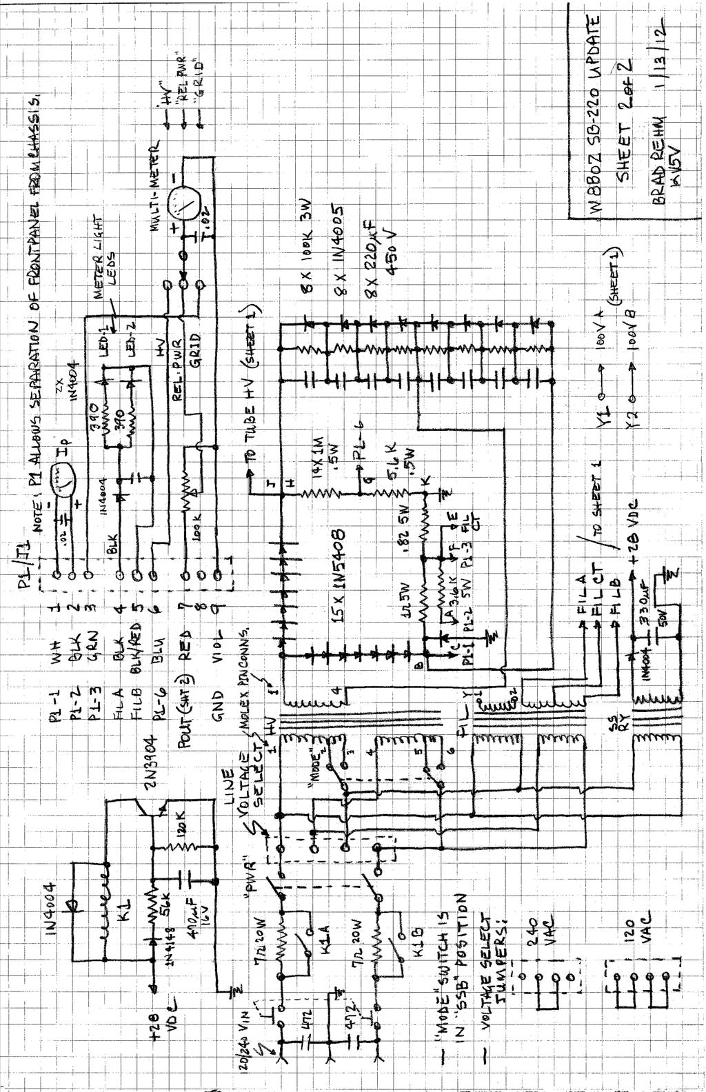
3 and the power cord entry. The cord and voltage-select jumpers have not yet been installed. For the final endurance change, we added a step-start circuit which limited the turn-on or inrush current due to the initial low resistance of the tube filaments and the high energy demanded by the filter capacitors when charging begins. I've used two approaches to this task in other amplifier projects. The simplest inserts a negative temperature coefficient (NTC) thermistor in series with one of the incoming AC mains. These devices present a relatively high resistance when cold and reduce their resistance to a small fraction of an Ohm when they become warm. Several commercial soft-start products use this approach. Another way to accomplish step-start places a resistor in series with one or both of the AC supply leads and uses a relay to shunt the resistors after a two or three second delay. The design of this kind of circuit is a little tricky because the circuitry that energizes the relay may have to work reliably at an initially low AC mains voltage. The resistor values must also be chosen carefully, because we would like them to be suitable for both 120 Volt and 240 Volt operation. I chose the relay approach, shown in Photo 2 above, using a simple R-C and transistor timer. The start-up current requirement of an amplifier of this size can exceed the current ratings of the largest NTC thermistors, especially when the amp is operated at 120 Volts. The relay approach can be very reliable if the resistors and relay are selected carefully. After a twosecond delay, two 15 Ohm, 5 Watt resistors in parallel in each leg of the incoming AC are removed, using a double-pole, 20 Amp relay. The component values allow the simple, 28-Volt delay circuit to operate properly at 120 and 240 Volts. Photo 2 shows the Magnecraft relay used to bypass each of the series resistors, which are located to the right and above the circuit breakers. The terminal strip to the left of the 3-500Z socket contains the 28 Volt rectifier and delay circuit. The transformer which powers this circuit was bolted to the side panel on the top of the chassis. It is shown in Photos 3 and 12. The final schematic includes the relay control circuit and 28 Volt power supply. Also in this category were the following convenience and appearance changes: 1. Molex connectors were installed in the high voltage transformer leads and in the wiring to the front panel. These are shown in Photos 3 and 4. The primary connectors were Molex and The secondary connectors were Molex and The incandescent lamps which illuminate the meters were replaced with white LEDs. The 5 Volt filament power was rectified and filtered, then current-limited with individual resistors for each LED. 3. Harbach capacitor board was installed in the power supply. In addition to improving the appearance of the capacitor bank, the capacitor board includes new bleeder resistors and adds reverse diodes to protect the amplifier during tube flashovers. The old and new capacitor wiring is show in Photos 5 and 6. Notice the damage to the original transformer secondary lead from arcing through the insulating sleeving in Photo The Harback SB-220 diode board uses newer 1N5408 diodes, which increase the peak current rating from 1 to 3 Amperes. An additional diode was installed on the back of the board to reduce the chance of damage from tube flashovers. (See the discussion of this change below.)


4 5. The ALC circuitry was removed because reliable ALC loops are already incorporated in modern transceivers. 6. The three-pole antenna- and biasswitching relay was discarded, and several components were added to replace it. The vacuum relays are shown in Photo 7. The upgrades accomplished with the W7RY QSK Board are discussed below. All coax in the SB-220 was replaced with Teflon dielectric, RG-303. Photo 3 Molex connectors as installed at the high voltage power transformer. The connectors make it easier to remove the transformer for shipping. The original transformer was replaced with a Harbach/Peter W. Dahl unit, which increased the available high voltage from about 3200 to nearly 3500 Volts. This photo also shows the Alpha Wire sleeving which was installed on the transformer secondary leads. The breakdown rating of the sleeving is 8000 Volts. Photo 4 The Harbach diode board, which replaces the original voltage doubler board. The area of this board which contained the zener diode replacement is not populated because this function is performed by the W7RY QSK Board. Also visible in this photo is the Molex connector which allows detaching and removing the front panel. The fuse, visible on the left side of the photo, protects the power


5 supply and meters from tube flashovers. Not visible here is the diode recommended by W8JI to provide additional flashover protection for the meters. It has been soldered to the back of the diode board between terminal C and ground. Photo 5 - The original capacitor and diode board wiring. Notice the arc damage to the original transformer secondary wire and sleeving. Photo 6 - The Harbach capacitor and diode boards replaced the original wiring and PWB. Alpha Wire sleeving was used on all the high voltage wiring. The new front panel wiring and white meter LEDs are also visible in this photo.
 to reduce mechanical switching noise.")
6 Photo 7 - Kilovac HC-2 vacuum relays are shown in this photo. The resistor which sets current through the relays at 60 ma will be installed on the terminal strip between the relays. The relays are mounted in rubber grommets (Mouser ) to reduce mechanical switching noise. Also visible in this photo are the parallel 10 Ohm resistors in series with the coax and RF drive to the filaments. These reduce the Q of the bandswitch-to-tube wiring. Improvements for Stability. Some SB-220s tended to develop parasitic oscillations, particularly when used on the higher HF bands. This problem appeared not only in the Heath amplifiers but in a number of competing production amps of the same vintage. The parasitic suppressors placed in series with each of the tube plate leads are usually responsible. You will find a variety of opinions about how suppressors should be built. Many designers feel that the three-to-five turn inductors around or adjacent to Q-killer resistors do not make good parasitic chokes. Even though the Q of these chokes can be made low, the fact that they're typically resonant in the VHF range means that they can support parasitics. Hairpin loops shunted by low-inductance resistors have self-resonant frequencies well above the VHF range and appear to work well as parasitic suppressors. The loops are typically just wide enough to allow the resistors to be soldered across the bases, and they are made somewhat longer than they are wide. I haven't seen the loop dimensions fully-defined yet, but Richard Measures, AG6K, gives a fairly complete description in his on-line paper on the TL- 922 and the SB-220. (See the Anode Circuit Modification section of Although Measures also recommends using nichrome wire for the loop, I have found 12-gauge, tinned buss wire to be satisfactory. Photo 8 shows the hairpin loops installed in this SB-220. Observing the output of the amp with a spectrum analyzer, I have found no tendency to oscillate, even under a variety of load conditions.

7 Photo 8 - The hairpin parasitic chokes are supported by the plate choke. The Q-killer resistors are placed at the bottom of each choke. Notice the ceramic disc capacitor which was added at the base of the plate choke. The new fan and motor are visible to the left of the tubes. The mounting bolts were replaced with longer ones, which permitted using fender washers on the inside and outside surfaces of the intake grill. These reduced motor vibration. The small transformer above the fan motor was later moved to the opposite side of the fan because the space was needed for the larger Peter W. Dahl transformer. Protecting Against Catastrophic Failure. This category could be subsumed under the stability improvement heading, since some failures are related to parasitic oscillations. I prefer to consider it separately because there is a class of failure which occurs because of sudden discharges inside the tubes. Design choices can't eliminate the chance of a discharge, but they can reduce the damage that follows when a discharge occurs. Tom Rauch, W8JI, has written a technically competent discussion of this phenomenon. (See Internal discharges typically occur between the anode (plate) of the tube and the cathode (or filament). When this happens the control grids can be driven positive, causing hundreds of amperes of current to flow through the tubes and their bias circuit. The tubes are lost. The meters are usually destroyed. And many smaller components fail. The first step in preventing this kind of damage is to abandon the practice of isolating the grids of the tubes from ground with chokes, resistors, or fuses. Photo 7 shows resistors installed between one of the grid terminals on each tube and each grid pin taken to RF ground with pairs of capacitors. These were replaced with buss wire connections to ground. The ground connection ensures that the grids can never be driven very positive in a flashover
8 event. Flashovers and damage can occur for other reasons; however, so additional changes were introduced. First, fast-blow, 1 Amp fuses were installed in series with the plate B+ lead and in series with the center tap of the filament transformer secondary. These limit the current which can flow during a flashover event. Second, a diode was installed from terminal C on the diode board to ground. Shown on the schematic, this diode clamps the negative rail, to which the plate current meter is connected, at about 1 Volt. Finally, a W7RY QSK Board was installed to improve amplifier operation and, most important, reduce the chance of a particular kind of failure. Jim offers (or plans to offer) boards for L4B, SB-200, Ameritron, and TL922 amps, as well as for the SB-220. The boards are sold on EBay ( Amplifier-QSK-System-/ ), but a brief explanation of how the design evolved can be found at The original Heathkit design rectified voltage from a separate winding on the filament transformer to develop about 115 Volts DC. This was applied to the antenna/bias changeover relay, and it appeared at the Relay connector at the rear of the amp. Modern transceivers are not designed to handle the voltage and current involved, so an interface is normally used to protect the transceiver. The QSK Board rectifies the AC from the transformer and uses a Zener diode to develop 12 Volts for on-board circuitry. The latter includes a transistor buffer which reduces Relay current seen by the transceiver to about 10 ma. The QSK Board includes two other important circuits. One is an adjustable, precisionregulated supply which drives a power-darlington transistor to control the 3-500Z operating bias. The transmit/standby bias levels are selected by a signal derived from the Relay circuit. The other circuit controls the antenna changeover relays. Jim recommends using a reed relay at the amp input and a vacuum relay at the output. His schematic includes resistors which equalize the currents in the two series-connected relays. Having had unhappy experiences with reed relays in other applications, Russ and I chose to use two Kilovac HC-2 vacuum relays. HC-1s might have been a better choice, but HC-2s were on-hand, and they have worked well in the project as well as several others. Since plenty of voltage is available to operate the series-connected relays, they switch very rapidly. A series resistor limits current to about 60 ma. Adding a capacitor across the resistor could have been used to further reduce switching time, but this was not deemed necessary. The QSK Board has a role in preventing catastrophic failures in the SB-220, because a failure mode of the Zener diode which controls cathode bias in the original circuit is a short circuit. When the Zener fails in this manner, the tubes are turned fully on, and damage can result when excessive current flows. The QSK Board uses a TIP147 power transistor which is protected by an MOV (a Metal-Oxide Varistor). If the transistor should fail, the voltage across the varistor would rise to its 130 Volt avalanche rating, thus biasing the tubes into cut-off. The normal failure mode for an MOV is to go open, but this only occurs after the part has been driven into conduction many times. The scheme isn't completely failure-proof, but I believe it's less failure-prone than the original circuit. The installed board is shown in Photo 9.

9 Photo 9 - The finished underside of the amp. The QSK Board is on the lower-right in this photo. The Darlington bias-control transistor and filament center-tap fuse are mounted just above it, using available chassis holes. Final Thoughts. With the exception of a transistor failure on the W7RY QSK board (probably a random failure event); the amp has performed well for several months. Some comments about its behavior are in order: Substituting the Harbach/Peter W. Dahl transformer for the original high-voltage transformer resulted in several changes in the behavior of the amp. The resting plate voltage increased from an indicated 3200 Volts to nearly 3500 Volts. As a result, less exciter power is required to drive the amp to 1500 Watts output. Prior to the change, 90 to 100 Watts of drive produced about 1400 Watts peak output in SSB mode. After the change, 80 to 90 Watts produced 1400 to 1500 Watts peak output. These measurements were made using an Array Solutions Power Master wattmeter and a Palstar DL2K load. More importantly, when the original 3-500Z tubes were replaced with new RF Parts 3-500ZGs, 1500 Watts was attainable with 70 to 80 Watts drive.

10 When the original tubes were used, other stations reported that transmitted audio sounded better less distorted when the drive power was reduced to 75 Watts. At this level, the power output was about 1200 Watts. The new RF Parts 3-500ZGs could be operated at 1400 to 1500 Watts with no degradation in signal quality. Clearly, to keep distortion products under control, we would have to settle for less power output with the original tubes. (The RF Parts tubes were borrowed for testing from another amplifier project.) Since I am primarily a CW op, I hoped to be able to run the SB-220 at full power from time to time. This not advisable, because the voltage rating of the plate tuning capacitor is not high enough to allow it. Arcing between the plates can occur at 1500 Watts, so CW on the SB-220 is recommended only in CW/TUNE mode, where output is about 1000 Watts with 80 Watts drive (using the original tubes). Curiously, I've seen no capacitor arc-overs when running the amp at 1500 Watts in SSB mode. On two occasions, idle current and power output fell to half normal. A quick look at the tubes revealed that one filament was not lit. Russ remembered that other SB-220 owners had reported that this can be caused by oxidation on the tube socket pin receptacles. I cleaned the receptacles with Q-tips which had been saturated in an electronic contact cleaner solution. The Q-tips turned dark. The tube filaments have lit reliably ever since. Photos 10 through 13 show the beginning stages of the project and the finished amp with the Harbach/Peter Dahl transformer installed, with the necessary changes to the enclosure. Photo 10 - Most components have been removed so that the chassis can be cleaned and old hardware can be replaced. The resistor which feeds high voltage to the bypass capacitor and plate choke was also replaced


11 Photo 11 - Another view of the chassis, ready for rewiring. One RCA connector on the rear of the chassis was removed. The other was replaced with a BNC at the Relay input. Photo 12 - This view shows the Harbach/Peter Dahl HV transformer, which is slightly larger than the original transformer. The 24 Volt transformer which supplies power for the step-start circuit has been moved to the lower-right corner to make room for the Harbach.

12 Photo 13 - It was necessary to cut a rectangular hole in the right-side panel to make room for the Harbach transformer. The transformer will not interfere with the outer enclosure for the amp. We would appreciate hearing about your SB-220 project. You may have comments about different approaches and better ways of doing what we did. If you'd like to hear the SB-220 in operation, join us and our friends on Saturday and Sunday mornings on MHz, 5:15 to 8:00 am, US central time. 73, Brad Rehm, KV5V (with Russ Gates, W8BOZ) 1/14/13 Nb. Looking at the schematics after having them scanned at an office supply store, I noticed something which everyone will want to correct. The fuse in the high-voltage line to the plate choke is on the supply side of the Interlock. If the cover plate is removed soon after turning the amp off, the Interlock will try to crowbar the supply, but the fuse will open when the current exceeds 1 amp. This will make the tube compartment safe, but the capacitors in the HV supply will probably not be fully discharged at this time. The solution: Either remove the Interlock switch and be careful! (Bad idea.) Or move the fuse. Install it in series with the HV lead to the RF choke. Be safe! (Good idea.) * * *
13
14
Notes on Rebuilding an SB-220 Linear Amplifier (Updated Jul/13)
") Notes on Rebuilding an SB-220 Linear Amplifier (Updated Jul/13) Brad Rehm, KV5V Salado, Texas Several months ago, I was asked to sell the radio equipment of an older ham who had moved to a retirement home.
Notes on Rebuilding an SB-220 Linear Amplifier (Updated Jul/13) Brad Rehm, KV5V Salado, Texas Several months ago, I was asked to sell the radio equipment of an older ham who had moved to a retirement home.
A 100-Watt Transmitter Using a Pair of VT1625s
 12/16/2007 6:00 PM VT1625 100 Watt Transmitter A 100-Watt Transmitter Using a Pair of VT1625s FIG. 10.6 A 100-watt transmitter for five bands, using salvaged TV power transformer and surplus 1625 amplifier
A 75-Watt Transmitter for 3 Bands Simplified Shielding and Filtering for TVI BY DONALD H. MIX, W1TS ARRL Handbook 1953 and QST, October 1951
 A 75-Watt Transmitter for 3 Bands Simplified Shielding and Filtering for TVI BY DONALD H. MIX, W1TS ARRL Handbook 1953 and QST, October 1951 The transmitter shown in the photographs is a 3-stage 75-watt
Modifying The Heath HA-14 For 6 Meters Greg Chartrand - W7MY 4/22/07
 Introduction The Heathkit HA-14 was one of the few electron tube linear amplifiers intended for mobile use but few were purchased with the 12 volt mobile power supply. Most hams bought the HA-14 for base
Manual AMERITRON QSK-5PC T/R SWITCH PC BOARD INTRODUCTION
 Manual Instruction AMERITRON QSK-5PC T/R SWITCH PC BOARD INTRODUCTION The Ameritron QSK-5PC is a PIN diode QSK circuit board designed for use in Ameritron's AL-80A, AL-80B, AL-82, AL-1500 and AL- 1200
PLEASE READ THIS MANUAL BEFORE ATTEMPTING TO OPERATE EQUIPMENT!!
 PLEASE READ THIS MANUAL BEFORE ATTEMPTING TO OPERATE EQUIPMENT!! UNPACKING INSTRUCTIONS 1. Carefully lift the amplifier by the bottom cabinet edge out of the shipping carton. Place the amplifier on a firm,
NOTE: The relay coil is polarity sensitive
 External QSK T/R Switch for HF Amplifiers Phil Salas AD5X Like many HF amplifiers, my Ameritron ALS-600 uses a power relay for T/R switching. The long 15-20ms enable/release time of this relay makes the
UNPACKING INSTRUCTIONS
 PLEASE READ THIS MANUAL BEFORE ATTEMPTING TO OPERATE EQUIPMENT!! UNPACKING INSTRUCTIONS 1. Carefully lift the amplifier by the bottom cabinet edge out of the shipping carton. Place the amplifier on a firm,
TL-922 Revival (tm) Kenwood TL-922 Linear Amplifier Hardware Upgrade Kit. Installation Manual
 Kenwood TL-922 Linear Amplifier Hardware Upgrade Kit. Installation Manual") TL-922 Revival (tm) Kenwood TL-922 Linear Amplifier Hardware Upgrade Kit Installation Manual P.O. Box 341543 Beavercreek, Ohio 45434 15 January, 2016 Copyright 2012 ii Thank-You! At Kessler Engineering,
TL-922 Revival (tm) Kenwood TL-922 Linear Amplifier Hardware Upgrade Kit Installation Manual P.O. Box 341543 Beavercreek, Ohio 45434 15 January, 2016 Copyright 2012 ii Thank-You! At Kessler Engineering,
IPR LA-3 KIT last update 15 march 06
 IPR LA-3 KIT last update 15 march 06 PART-2: Audio Circuitry CIRCUIT BOARD LAYOUT: Power and Ground Distribution Now that your power supply is functional, it s time to think about how that power will be
ALS-1306 Vacuum relay modification
 ALS-1306 Vacuum relay modification This modification installs two vacuum relays in the amplifier to allow nearly silent QSK operation. NG7M first did the modification to his ALS-1300 with input from Tom,
SoftRock v6.0 Builder s Notes. May 22, 2006
 SoftRock v6.0 Builder s Notes May 22, 2006 Be sure to use a grounded tip soldering iron in building the v6.0 SoftRock circuit board. The soldering iron needs to have a small tip, (0.05-0.1 inch diameter),
Review: The Ameritron ALS Watt HF Power Amplifier Phil Salas AD5X
 Review: The Ameritron ALS-1300 1200-Watt HF Power Amplifier Phil Salas AD5X Introduction The new Ameritron ALS-1300 is a 160-10 meter 1200 watt output all solid-state amplifier with manual band switching
Central Electronics Model 600L Linear Amplifier
 INTRODUCTION This manual has been reproduced by James Lawrence, NA5RC, a 600L owner. Text no longer applicable such as insurance claim with the carrier has been deleted. Some capitalization and grammar
Hot Water for the K2. K1RFD Building the K2 More K2 Photos. Using an HW-101 as a 100-watt PA. Hot Water for the K2. EchoStation
 Page 1 of 5 K1RFD Building the K2 More K2 Photos EchoStation Using an HW-101 as a 100-watt PA When I was a young ham in 1977, I saved money to buy and build a Heathkit HW-101. The rig has served me well
Ameritron QSK-5/Kenwood TS-570/Relay-free Ameritron AL-811H Use
 Ameritron QSK-5/Kenwood TS-570/Relay-free Ameritron AL-811H Use After getting a used QSK-5, I studied up on the history and required convoluted interpretation of the manual for my application to the TS-570
 KILOWATT GROUNDED-GRID LINEAR AMPLIFIER (Radiotron HB) Grounded-grid amplifiers The input voltage is applied to the cathode, the grid is earthed, and the output is taken from the plate, being in phase
Instructions MODIFICATION KIT MODEL SBM - 1O2-1 INTRODUCTION PARTS LIST FOR THE
 Instructions FOR THE MODIFICATION KIT MODEL SBM - 1O2-1 INTRODUCTION This modification Kit applies to the following Heath Transceivers: 1. All Models HW-100, SB-100, SB-101 and SB-101W. 2. Any Model SB-102
HOM rev. new Heathkit of the Month #79: by Bob Eckweiler, AF6C. Heath of the Month #79 - VF-1 VFO AMATEUR RADIO - SWL
 Heathkit of the Month #79: by Bob Eckweiler, AF6C AMATEUR RADIO - SWL Heathkit VF-1 External VFO (Variable Frequency Oscillator). Introduction: In 1951 the FCC totally revamped the license classes for
SUBELEMENT T6 Electrical components: semiconductors; circuit diagrams; component functions 4 Exam Questions - 4 Groups
 SUBELEMENT T6 Electrical components: semiconductors; circuit diagrams; component functions 4 Exam Questions - 4 Groups 1 T6A Electrical components: fixed and variable resistors; capacitors and inductors;
How The Transmitter Works
 Mike Bray, K8DDB Refer to the schematic of the transmitter on page 7 of the manual. The crystal-controlled oscillator, V generates a small amount of r.f. power which is used to drive the amplifier, V2.
4/30/2012. General Class Element 3 Course Presentation. Practical Circuits. Practical Circuits. Subelement G7. 2 Exam Questions, 2 Groups
 General Class Element 3 Course Presentation ti ELEMENT 3 SUB ELEMENTS General Licensing Class Subelement G7 2 Exam Questions, 2 Groups G1 Commission s Rules G2 Operating Procedures G3 Radio Wave Propagation
DEM TC DEM TRANSVERTER CONTROL
 DEM TC DEM TRANSVERTER CONTROL The DEM Transverter Control (DEM TC) is the circuit board that controls all transverter functions in the DEMI 2.3 GHz. -10 GHz. transverters. It was designed with many options
My experience with the ANC-4 on 50 MHz Rev. 1
 My experience with the ANC-4 on 50 MHz Rev. 1 by Antonio Vernucci, I0JX 1. General The ANC-4 (Antenna Noise Canceller - 4) is intended to reduce the impairment of weak DX signals reception caused by local
SECTION NEUTRALIZATION BELOW VHF NEUTRALIZATION
 SECTION 5 NEUTRALIZATION A completely neutralized amplifier must fulfill two conditions. The first is that the interelectrode capacitance between the input and output circuits be cancelled. The second
SoftRock v6.0 Builder s Notes. April 6, 2006
 SoftRock v6.0 Builder s Notes April 6, 006 Be sure to use a grounded tip soldering iron in building the v6.0 SoftRock circuit board. The soldering iron needs to have a small tip, (0.05-0. inch diameter),
Assembly Instructions for the FRB FET FM 70 Watt Amp
 Assembly Instructions for the FRB FET FM 70 Watt Amp 1.) Orient the circuit board with the diagram 2.) Use a narrow chisel tip 25-30 watt soldering iron for assembly 3.) All the small parts are taped onto
The Electro-Magnetic Spectrum
 The Electro-Magnetic Spectrum Part Three In This Issue: All about Tubes How a diode rectifier works How a triode amplifier works How the mixer in your receiver works Dear Friends: For quite some time I
SoftRock v5.0 Builder s Notes. December 12, Building a QSD Kit
 SoftRock v5.0 Builder s Notes December 12, 2005 Building a QSD Kit Be sure to use a grounded tip soldering iron in building the QSD board. The soldering iron needs to have a small tip, (0.05-0.1 inch diameter),
Construction Manual 6m-Linear-Transverter XV6/10
 Construction Manual 6m-Linear-Transverter XV6/10 Holger Eckardt DF2FQ Kirchstockacherstr. 33 D-85662 Hohenbrunn 2606 Technical data exciter frequency: 28... 30 MHz RF frequency: 50... 52 MHz supply voltage:
Practical Tricks with Transformers. Larry Weinstein K0NA
 Practical Tricks with Transformers Larry Weinstein K0NA Practical Tricks with Transformers Quick review of inductance and magnetics Switching inductive loads How many voltages can we get out of a $10 Home
ACØC SB200 SLEEPER. Xtreme Conversion
 ACØC SB200 SLEEPER Xtreme Conversion SB200 STOCK CONFIGURATION 2x572B glass triodes 320W plate disipation 2400v idle; 2100v loaded @ 500ma 500w typical output (800w on fresh tubes) 80-10m operation STOCK
Instruction Manual OM3500 HF SHORTWAVE POWER AMPLIFIER. OM POWER, s. r. o Bác 126 SLOVAKIA
 Instruction Manual OM3500 HF SHORTWAVE POWER AMPLIFIER OM POWER, s. r. o. 930 30 Bác 126 SLOVAKIA Important safety instructions: The amplifier contains high voltage circuits. Never turn the amplifier on
The 6LE8 One Tube Broadcaster
 The 6LE8 One Tube Broadcaster Introduction The purpose of this broadcaster is to transmit your favorite music to every AM radio in your home. The transmitting power is so low that it should not bother
PL8877/ 3CX1500A7 High-Mu Power Triode
 PL8877/ 3CX1500A7 High-Mu Power Triode The Penta Laboratories PL8877/3CX1500A7 is a rugged ceramic and metal power triode designed for use as cathode driven Class AB2 or Class B amplifi er in audio or
SB-220 or 221. The Heathkit SB-220/221 Vintage Linear Amplifier. A Great Buy at Today s Prices. Tom Sowden (K0GKD)
") 1 of 32 7/25/2013 6:21 PM SB-220 or 221 The Heathkit SB-220/221 Vintage Linear Amplifier A Great Buy at Today s Prices Tom Sowden (K0GKD) 2 of 32 7/25/2013 6:21 PM www.k0gkd.com QST January 2007 With the
1 of 32 7/25/2013 6:21 PM SB-220 or 221 The Heathkit SB-220/221 Vintage Linear Amplifier A Great Buy at Today s Prices Tom Sowden (K0GKD) 2 of 32 7/25/2013 6:21 PM www.k0gkd.com QST January 2007 With the
Dentron Clipperton L Conversion to GI-7B Tubes and Other Modifications. Pat Griffin AA4PG
 Dentron Clipperton L Conversion to GI-7B Tubes and Other Modifications Pat Griffin AA4PG Walking out of Dayton, 2014 my eye caught a beat up Clipperton cabinet under a vendor table. Twenty bucks and it
GRID CONTROLLED POWER SUPPLY IS A VERSATILE UNIT Uses Pair of RCA-2050 s for Wide Voltage Range
 10/30/07 11:55 PM Thyratrons GRID CONTROLLED POWER SUPPLY IS A VERSATILE UNIT Uses Pair of RCA-2050 s for Wide Voltage Range By J. H. OWENS, W2FTW and G. D. HANCHETT, W1AK/2 RCA Ham Tips Volume 6, Number
75 Meter SSB Project Design by KD1JV Built by Paul Jorgenson KE7HR NSS 39382FE
 75 Meter SSB Project Design by KD1JV Built by Paul Jorgenson KE7HR NSS 39382FE After completing a 75 meter DSB project (and using it underground, caving), I wanted to try building a SSB rig. I was searching
WA3RNC 30 METER CRYSTALPLEXER TRANSMITTER KIT ASSEMBLY INSTRUCTIONS
 WA3RNC 30 METER CRYSTALPLEXER TRANSMITTER KIT ASSEMBLY INSTRUCTIONS Description The WA3RNC 30 Meter Crystalplexer is a low power crystal controlled QRP transmitter offering a significantly improved tuning
The Aleph 5 is a stereo 60 watt audio power amplifier which operates in single-ended class A mode.
 Pass Laboratories Aleph 5 Service Manual Rev 0 9/20/96 Aleph 5 Service Manual. The Aleph 5 is a stereo 60 watt audio power amplifier which operates in single-ended class A mode. The Aleph 5 has only two
Preliminary Ver. 1.16A
 ALPHA 9500 HF Power Amplifier Test Report for Grant of Certification for Use in Part 97 Amateur Service under the Rules of the Federal Communications Commission DGVPA-77DF February 23, 2010 Submitted by:
MISCELLANEOUS. Figure 1.
 Reading 41 Ron Bertrand VK2DQ http://www.radioelectronicschool.com MISCELLANEOUS The purpose of this reading is to catch anything that may have slipped through the previous forty readings or just does
COMMANDER HF-2500 COMMANDER HF-2500 MAGNUM. Owner s Manual. PALSTAR, INC. Command Technologies Division 9676 N. Looney Road Piqua, Ohio U.S.A.
 COMMANDER HF-2500 COMMANDER HF-2500 MAGNUM Owner s Manual PALSTAR, INC. Command Technologies Division 9676 N. Looney Road Piqua, Ohio 45356 U.S.A. Customer Service and Sales Telephone: 800-773-7931 International:
SPECIFICATIONS. 1,500 Watts SSB, 1250 Watts CW, 800 Watts RTTY, FM, SSTV
 QRO HF-2000 LINEAR AMPLIFIER INSTRUCTION MANUAL QRO TECHNOLOGIES, INC. 1117 West High Street P.O. Box 939 Bryan, OH 43506 USA Tel & Fax: (419) 636-2721 E-Mail: sales@qrotec.com Internet: http://www.qrotec.com
4/30/2012. General Class Element 3 Course Presentation. Circuit CoCircuit Componentsmponents. Subelement G6. 3 Exam Questions, 3 Groups
 General Class Element 3 Course Presentation ti ELEMENT 3 SUB ELEMENTS General Licensing Class Subelement G6 Circuit Components 3 Exam Questions, 3 Groups G1 Commission s Rules G2 Operating Procedures G3
LBI-4938C. Mobile Communications MASTR II POWER AMPLIFIER MODELS 4EF4A1,2,3. Printed in U.S.A. Maintenance Manual
 C Mobile Communications MASTR II POWER AMPLIFIER MODELS 4EF4A1,2,3 Printed in U.S.A. Maintenance Manual TABLE OF CONTENTS DESCRIPTION.................................................... 1 CIRCUIT ANALYSIS.................................................
CX7 Troubleshooting Index
 CX7 Troubleshooting Index Modification S/1 Newsletter Guide Board Description A/TO A/TO MODE Intermod V1,12 P4.4 A11 Shut off one 35 MHz osc in receive, done sn 244 A/TO Spur V1,12 P1 Reduce A/TO spur,
The Vibrator Power Supply
 The Vibrator Power Supply Function: The function of the vibrator power supply is like that of the AC operated supply - to provide the necessary voltages for the receiver. In this case the voltage source
HIGH-MU AIR-COOLED POWER TRIODE 3CX1500D7
 TECHNICAL DATA HIGH-MU AIR-COOLED POWER TRIODE 3CX1500D7 The Eimac 3CX1500D7 is a compact power triode with an anode dissipation rating of 1500 watts. This tube features a filament designed to operate
The ROSE 80 CW Transceiver (Part 1 of 3)
") Build a 5 watt, 80 meter QRP CW Transceiver!!! Page 1 of 10 The ROSE 80 CW Transceiver (Part 1 of 3) Build a 5 watt, 80 meter QRP CW Transceiver!!! (Designed by N1HFX) A great deal of interest has been
Build a 5 watt, 80 meter QRP CW Transceiver!!! Page 1 of 10 The ROSE 80 CW Transceiver (Part 1 of 3) Build a 5 watt, 80 meter QRP CW Transceiver!!! (Designed by N1HFX) A great deal of interest has been
QUICKSILVER MX-190 OPERATING INSTRUCTIONS ,,-
 QUICKSILVER MX-190 OPERATING INSTRUCTIONS -------..,,- INPUT CONNECTIONS To maintain a short and concise signal path, the input connectors are mounted directly on the plug-in front-end circuit boards.
Building a Dummy Load and Measuring Power Accurately by Ken, K4EAA. Building the Dummy Load
 Building a Dummy Load and Measuring Power Accurately by Ken, K4EAA Building the Dummy Load This is a take-off on a Dummy load that I've built in many different forms over the years. It uses a number of
REPAIRING THE RM KL400 LINEAR AMPLIFIER.
 REPAIRING THE RM KL400 LINEAR AMPLIFIER. Les Carpenter G4CNH December 2012 Page 1 of 20 The following is a step by step guide to fixing your KL400 amplifier. Each part will be individually tested up to
Construction Manual 4m-Linear-Transverter XV4-15
 Construction Manual 4m-Linear-Transverter XV4-15 Holger Eckardt DF2FQ Kirchstockacherstr. 33 D-85662 Hohenbrunn 3207 Technical data exciter frequency: 21.0... 21.5 MHz RF frequency: 70.0.. 70.5 MHz supply
HW-8-TR V3 PARTS LIST
 HW-8-TR V3 PARTS LIST Qty Ref Description Markings 4C2 C3 C4 C5 Capacitor Disc.1ls.1uF 104 1 C1 Capacitor Disc.2ls.1uF 100V 104 1 QSKMOD-C92 Capacitor Electrolytic 1uF 50V 1 QSKMOD Capacitor Mylar.47uF
For the filter shown (suitable for bandpass audio use) with bandwidth B and center frequency f, and gain A:
 with bandwidth B and center frequency f, and gain A:") Basic Op Amps The operational amplifier (Op Amp) is useful for a wide variety of applications. In the previous part of this article basic theory and a few elementary circuits were discussed. In order to
Basic Op Amps The operational amplifier (Op Amp) is useful for a wide variety of applications. In the previous part of this article basic theory and a few elementary circuits were discussed. In order to
How to use your antenna tuner.
 How to use your antenna tuner. There's more to it than what is in your manual or on most how to do it websites! http://www.arrl.org/tis/info/ant-tuner-op.html Here is a neat site with a "T" network simulator.
OM1006 Solid State 50 MHz Power Amplifier
 Instruction Manual OM1006 Solid State 50 MHz Power Amplifier OM POWER, s. r. o. 930 30 Báč 126 SLOVAKIA E-mail: om-power@om-power.com TABLE OF CONTENTS 1. GENERAL INFORMATION 1.1. Introduction.. 4 1.2.
V6.2 SoftRock Lite Builder s Notes. November 17, 2006
 V6.2 SoftRock Lite Builder s Notes November 17, 2006 Be sure to use a grounded tip soldering iron in building the v6.2 SoftRock circuit board. The soldering iron needs to have a small tip, (0.05-0.1 inch
- have been successfully combined in the RCA -developed insulated -gate metal -oxide -
 A PUBLICATION OF RCA ELECTRONIC COMPONENTS AND DEVICES VOL. 27, NO. 3 1967, RADIO CORPORATION OF AMERICA OCTOBER, 1967 Using the MOS Field -Effect Transistor As a Product Detector and AGC Gate By W. M.
Figure 2 shows the actual schematic for the power supply and one channel.
 Pass Laboratories Aleph 3 Service Manual rev 0 2/1/96 Aleph 3 Service Manual. The Aleph 3 is a stereo 30 watt per channel audio power amplifier which operates in single-ended class A mode. The Aleph 3
D. Gillespie Designs. SCA-35 Capacitor Board. Installation Manual. D. Gillespie Designs with EFB TM
 D. Gillespie Designs SCA-5 Capacitor Board with EFB TM Installation Manual D. Gillespie Designs www.tronola.com Thank you for choosing our SCA-5 Capacitor Board with *EFB. We feel it is the single most
The Aleph 2 is a monoblock 100 watt audio power amplifier which operates in single-ended class A mode.
 Pass Laboratories Aleph 2 Service Manual Rev 0 2/1/96 Aleph 2 Service Manual. The Aleph 2 is a monoblock 100 watt audio power amplifier which operates in single-ended class A mode. The Aleph 2 has only
Building the Sawdust Regenerative Receiver
 Building the Sawdust Regenerative Receiver Introduction The Sawdust is a super regenerative receiver using the basic Armstrong design architecture. The receiver uses one toroidal transformer to provide
INSTRUCTIONS FOR INSTALLATION AND OPERATION OF THE MEISSNER SIGNAL SHIFTER MODEL EX
 INSTRUCTIONS FOR INSTALLATION AND OPERATION OF THE MEISSNER SIGNAL SHIFTER MODEL EX I. INTRODUCTION A. The MEISSNER SIGNAL SHIFTER is a variable frequency exciter, with output over the entire ranges of
The ETO-Alpha 89 ETO-Alpha 89
 ETO-Alpha 89 The 89 was produced from 12/92 to 9/2000, 408 units were built during this time. These units were much like the 86, but with many updates and refinements. The 89 uses a pair of 3CX800A7 triodes
Step by Step Building PJ meter ARDF Receiver Kit. CRKITS.COM August 5, 2013
 Step by Step Building PJ-80 80-meter ARDF Receiver Kit CRKITS.COM August 5, 2013 What is ARDF? ARDF is the abbreviation of Amateur Radio Direction Finding, or so called Fox Hunting. If you are looking
Hamvention 2010 Drake Forum Slide Presentation Part Two of Three
 Hamvention 2010 Drake Forum Slide Presentation Part Two of Three AC-4r Upgrade Michael Bryce www.theheathkitshop.com Flea Market Space #509-510 Drake L7R Power Supply Board AC-4r Upgrade Michael Bryce
Power Supplies and Circuits. Bill Sheets K2MQJ Rudolf F. Graf KA2CWL
 Power Supplies and Circuits Bill Sheets K2MQJ Rudolf F. Graf KA2CWL The power supply is an often neglected important item for any electronics experimenter. No one seems to get very excited about mundane
Op Amp Booster Designs
 Op Amp Booster Designs Although modern integrated circuit operational amplifiers ease linear circuit design, IC processing limits amplifier output power. Many applications, however, require substantially
 file:///c /BoatAnchors/Hammarlund/HQ170A/HQ170SVC.TXT Dear OM: This form is being prepared to provide prompt attention to a complaint as a result of trouble that may be experienced in the field. In addition
Knight Kit V44 VFO Stabilized by the Cumbria Design X-Lock 3.0
 Knight Kit V44 VFO Stabilized by the Cumbria Design X-Lock 3.0 The Knight V44 VFO has a place in history. It was designed in the late 1950 s as a self contained VFO intended to plug into the crystal socket
G6ALU 20W FET PA Construction Information
 G6ALU 20W FET PA Construction Information The requirement This amplifier was designed specifically to complement the Pic-A-Star transceiver developed by Peter Rhodes G3XJP. From the band pass filter an
LDG TW-1 Talking Wattmeter
 LDG TW-1 Talking Wattmeter LDG Electronics 1445 Parran Road, PO Box 48 St. Leonard MD 20685-2903 USA Phone: 410-586-2177 Fax: 410-586-8475 ldg@ldgelectronics.com www.ldgelectronics.com 1 LDG TW-1 Talking
4X150A/7034 Radial Beam Power Tetrode
 4X15A/734 Radial Beam Power Tetrode T The Svetlana 4X15A/734 is a compact radial beam tetrode. The 4X15A is intended for Class AB SSB linear RF amplifier service. It is intended for stationary and mobile
Parallel Port Relay Interface
 Parallel Port Relay Interface Below are three examples of controlling a relay from the PC's parallel printer port (LPT1 or LPT2). Figure A shows a solid state relay controlled by one of the parallel port
User Guide for the Alpha Loop Sr Antenna
 User Guide for the Alpha Loop Sr Antenna Manufactured by: Alpha Antenna 1.888.482.3249 Website: http://alphaantenna.com Available from: Amateur Radio Store Website: https://amateurradiostore.com User Guide
Efficiency: 68% Temperature Range: +0 to 60 C Max VSWR: 5:1. Class: Supply Voltage:
 Part Number Revision 2.C Release Date July 11 2007 Revision Notes - updated new format Amplifier Name Technical Specifications Summary Frequency Range: P1dB: Class: Supply Voltage: 88-108 MHz 750 Watts
Using Ferrite Beads Keep RF Out of TV Sets, Telephones, VCR's Burglar Alarms and other Electronic Equipment
 Using Ferrite Beads Keep RF Out of TV Sets, Telephones, VCR's Burglar Alarms and other Electronic Equipment RFI and TVI have been with us for a long time. Now we have microwave ovens, VCR's and many other
Frequency Range: MHz. Efficiency: 80% Temperature Range: -20 to 65 C Max VSWR: 3:1. Class: Supply Voltage: 32.0V
 Part Number Revision 0.B Release Date October 19, 2007 Revision Notes Final production release Amplifier Name Technical Specifications Summary Frequency Range: 86-108 MHz P1dB: 500 Watts CW Class: C Supply
Basic Electronics. Chapter 2, 3A (test T5, T6) Basic Electrical Principles and the Functions of Components. PHYS 401 Physics of Ham Radio
 Basic Electrical Principles and the Functions of Components. PHYS 401 Physics of Ham Radio") Basic Electronics Chapter 2, 3A (test T5, T6) Basic Electrical Principles and the Functions of Components Figures in this course book are reproduced with the permission of the American Radio Relay League.
Basic Electronics Chapter 2, 3A (test T5, T6) Basic Electrical Principles and the Functions of Components Figures in this course book are reproduced with the permission of the American Radio Relay League.
Modification of the AM For 432 MHz
 Modification of the AM6154-6155 For 432 MHz by Ron Whitsel, W3RJW Updated 1/18/04 It seems the modifications to the venerable Fair Radio FAA amps for use on 432 has been lost in space. Following are the
Using the EVM: PFC Design Tips and Techniques
 PFC Design Tips and Techniques Features: Bare die attach with epoxy Gold wire bondable Integral precision resistors Reduced size and weight High temperature operation Solder ready surfaces for flip chips
1 FUNCTIONAL DESCRIPTION WAY SPLITTER/INPUT BOARD FET RF AMPLIFIERS WAY POWER COMBINER VSWR CONTROL BOARD...
 CONTENTS 1 FUNCTIONAL DESCRIPTION...1 2 4-WAY SPLITTER/INPUT BOARD...2 3 FET RF AMPLIFIERS...3 4 4-WAY POWER COMBINER...4 5 VSWR CONTROL BOARD...5 6 ADJUSTMENT OF BIAS VOLTAGE TO ESTABLISH PROPER QUIESCENT
FROM SCHEMATIC TO VEROBOARD
 FROM SCHEMATIC TO VEROBOARD The circuit of a bench amplifier utilising a LM386 linear (integrated circuit) IC and a few other components is used for this tutorial. The schematic is shown below: First a
How Vacuum Tubes in Linear Circuits Work
 How Vacuum Tubes in Linear Circuits Work By: w8ji.com How the PA Tube Converts DC anode voltage to Radio Frequency Power A typical vacuum tube radio-frequency amplifier has a high voltage power source.
General Licensing Class Circuits
 General Licensing Class Circuits Valid July 1, 2011 Through June 30, 2015 1 Amateur Radio General Class Element 3 Course Presentation ELEMENT 3 SUB-ELEMENTS (Groupings) Your Passing CSCE Your New General
Troubleshooting Tutorial Page 1 Tech Note 4
 Page 1 Tech Note 4 Tools Required: RCA shorting plugs (Fabricate using Radio Shack # 274-339) Digital Voltmeter Soldering Iron & Associated items Screw drivers, Pliers (including needle nose), wire cutters
3 Circuit Theory. 3.2 Balanced Gain Stage (BGS) Input to the amplifier is balanced. The shield is isolated
 Input to the amplifier is balanced. The shield is isolated") Rev. D CE Series Power Amplifier Service Manual 3 Circuit Theory 3.0 Overview This section of the manual explains the general operation of the CE power amplifier. Topics covered include Front End Operation,
Rev. D CE Series Power Amplifier Service Manual 3 Circuit Theory 3.0 Overview This section of the manual explains the general operation of the CE power amplifier. Topics covered include Front End Operation,
Copyright 2012, R. Eckweiler & OCARC, Inc. Page 1 of 5
 Heathkit of the Month #42: by Bob Eckweiler, AF6C Heathkit HD-1422-A Antenna Noise Bridge Introduction: If you work with antennas, an antenna noise bridge can be a very handy tool. Table 1 lists some of
A Water Cooled Amplifier for 23 cm
 By Jim Klitzing, W6PQL A Water Cooled Amplifier for 23 cm The Russian GS-15B tetrode may not put a full gallon in your shack, but how about a quart and a half? This 400 W amp is a compact, desktop package.
sb401-eco.txt Engineering change orders or Service Bulletions (all) [No date on fiche] LMO Change
![sb401-eco.txt Engineering change orders or Service Bulletions (all) [No date on fiche] LMO Change](/thumbs/95/124083994.jpg "sb401-eco.txt Engineering change orders or Service Bulletions (all) [No date on fiche] LMO Change") Engineering change orders or Service Bulletions (all) [No date on fiche] LMO Change -1D The [PN 110-32] is no longer available. In order to use [PN 100-40-LMO] it is necessary to add decoupling capacitors
Engineering change orders or Service Bulletions (all) [No date on fiche] LMO Change -1D The [PN 110-32] is no longer available. In order to use [PN 100-40-LMO] it is necessary to add decoupling capacitors
UNPACKING INSTRUCTIONS
 1 2 UNPACKING INSTRUCTIONS 1. Carefully remove the amplifier, transformer, and tube from their shipping cartons. Inspect each item for visible damage. If any damage occurred during shipment, notify the
OPERATING MANUAL ME500-H/-F/-V/-U, ME750-H/-F/-V/-U ME1200/1500-H/-F/-V/-U LINEAR AMPLIFIERS LED BARGRAPH FRONTPAGE VERSION
 OPERATING MANUAL ME500-H/-F/-V/-U, ME750-H/-F/-V/-U ME1200/1500-H/-F/-V/-U LINEAR AMPLIFIERS LED BARGRAPH FRONTPAGE VERSION M+E Mechanics & Electronics Inc. Hungary Draskovits Gábor HA1YA Szombathely,
LM125 Precision Dual Tracking Regulator
 LM125 Precision Dual Tracking Regulator INTRODUCTION The LM125 is a precision, dual, tracking, monolithic voltage regulator. It provides separate positive and negative regulated outputs, thus simplifying
Experimenting with a Stellex YIG Oscillator
 Overview Experimenting with a Stellex YIG Oscillator Stellex 6755 726 (Endwave MY01210) tunable mini YIG oscillators are starting to show up on Ebay for around $20 to $40. Most of these YIGs cover the
The Sunnyvale/Saint Petersburg Kilowatt-Plus
 The Sunnyvale/Saint Petersburg Kilowatt-Plus This article describes a modern 1500-W output linear amplifier for the amateur HF bands. It uses a relatively recent arrival on the transmitting tube scene
5/1.0 kw AM Transmitter
 5/1.0 kw AM Transmitter Collins' 820E /F -1 series of broadcast transmitters is one of the most extensively transistorized series of transmitters available in the 5 -kw to 10 -kw power range. The series
8984 Power Tube. VHF Linear Beam Power Tube
 8984 Power Tube HF Linear Beam Power Tube Full Input to 300 MHz Forced-Air Cooled 55 kw Peak Sync. Output HF-T Band 16dB Gain FM Broadcast Service 55 kw Output 16dB Gain The BURLE 8984 is designed specifically