Boom Distance Influence on Yagi Antenna Dragoslav Dobričić, YU1AW (Serbia)
|
|
|
- Theodora McLaughlin
- 6 years ago
- Views:
Transcription

1 Boom Distance Influence on Yagi Antenna Dragoslav Dobričić, YU1AW (Serbia) Introduction In a previous article [1] we investigated boom radius influence on six Yagi antennas very similar in all characteristics except in Q factor values [3]. Now, using computer simulations, we will investigate how fixed radius boom on various distances from antenna elements influences Yagi antenna parameters. For this task antenna simulation software based on FIT method has been used, instead of usual MoM based software which has been found inadequate due to a few unacceptable program limitations [2]. Boom influence has been monitored on following antenna parameters: 1. Antenna input return loss (S11) given in db 2. Broadband directivity given in db over isotropic radiator 3. Antenna directivity pattern in E and H planes Yagi antennas were simulated without boom and later with a 50 mm diameter conductive round tube boom added. The boom was placed below the elements so that the distance (x) between the boom axis and elements axis has been varied from 30 to 300 mm. Elements height above the boom, i.e. insulation gap between the boom s top-most surface and element s bottom-most surface was h = x br r where br=25 mm is boom radius and r is corresponding antenna element radius (Fig.1). It represented a simulation of a Yagi antenna with elements insulated from a boom and mounted on boom using plastic insulators with very low dielectric permittivity and different height of elements above the boom. Fig.1 antennex Issue No. 148 August 2009 Page 1
2 Simulation results On the presented diagrams on Fig. 2 it can be seen that curves of antenna input return loss shift toward higher frequency simultaneously with the decrease of the distance between boom and antenna elements. This is a result of the well known effect predicted by theoretical calculations and verified by practical measurements. The presence of a thick conductive boom close to the elements tends to shorten the effective length of the elements and thus shifts performances of the antenna to a higher frequency. Maximum of antenna input return loss (minimum SWR), maximum antenna directivity and other characteristics also shift to a higher frequency. Antenna radiation diagram also changes, in a way that side lobes and back lobe change their magnitude and angular position related to main lobe. It is very interesting that for some antennas, at large distances of mm between boom and elements, frequency shift of maximum input return loss becomes very small compared to input return loss of the same antenna without boom, but directivity and radiation pattern still considerable differ. This fact shows that it is not always possible to estimate whether antenna suffers from some destructive influence from its surrounding by simple measuring antenna input return loss or SWR. It would be very interesting to investigate how far from antenna elements the boom should be in order to have influence small enough that it could be neglected. In one of the next articles we will try to answer this question. Input Return Loss From the presented diagrams on Fig. 2 of input return loss, considerable shift toward higher frequencies when boom distance decreases can be seen. Frequency shift of maximum input return loss is MHz for antennas with a very close boom compared to antennas with no boom. Considering 2 m amateur band width of 2 MHz in Europe it is very high value! Variation of input return loss and maximum within frequency for DX band and whole European band MHz are given in Table 1. From results in Table 1 it is obvious that antennas with lower average Q factors have less variation and of input return loss due to variation of boom distance in chosen frequency bands. antennex Issue No. 148 August 2009 Page 2

3 Fig.2 antennex Issue No. 148 August 2009 Page 3
4 Table 1 Antenna type Dry/Wet antenna average Q factor Return Loss variation MHz Return Loss MHz Return Loss variation MHz Return Loss MHz DL6WU / DJ9BV / K1FO / DK7ZB / SA / EF0213-Q / Broadband directivity As expected, antenna broadband directivity curves given on Fig. 3 also shift toward higher frequencies due to a conductive boom influence. This effect produces significant variation of antenna directivity within the amateur band width. This directivity variation is given in Table 2 for whole (European) band MHz and for DX part MHz. Antenna directivity variation due to the impact of variable conductive boom proximity within these two frequency bands is given together with maximum directivity s that can be expected within bands. Antennas with high average Q factor show higher value of directivity variation as a result of higher sensibility to boom influence and narrower working bandwidth. Table 2 Antenna type Dry/Wet antenna average Q factor Directivity variation MHz Directivity MHz Directivity variation MHz Directivity MHz DL6WU / DJ9BV / K1FO / DK7ZB / SA / EF0213-Q / antennex Issue No. 148 August 2009 Page 4
5 Fig.3 antennex Issue No. 148 August 2009 Page 5

6 E-plane E-plane E-plane antennex Issue No. 148 August 2009 Page 6


7 H-plane H-plane H-plane antennex Issue No. 148 August 2009 Page 7
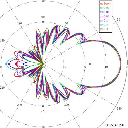
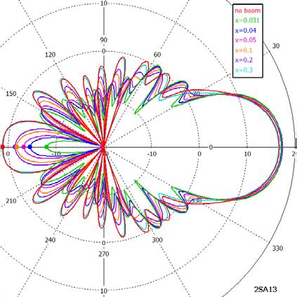
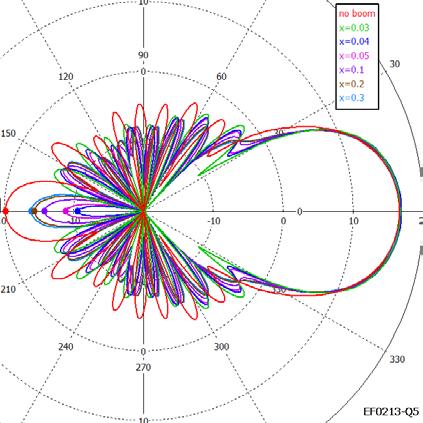
8 Antenna pattern All antenna patterns were taken on frequency MHz. This frequency is chosen because the antennas with high average Q factors usually have considerably distorted radiation patterns on higher frequencies. They are usually computer optimized only for work at the lower portion of the 2 m band and thus they are conditioned for this choice of frequency. On the presented polar plots of antenna directivity in E and H plane it can be seen that largest impact of a conductive boom is on angular position and magnitude of the first side lobes and the back lobe. Antennas with low average Q factors show a more stable angular position and less magnitude variation of side lobes in both E and H planes. Variation of back lobe magnitude with a change of boom distance is also lower for antennas with lower average Q factors. First side lobe magnitude and angular position s for all six antennas are given in Table 3. Back lobe variation and thus antenna F/B ratio variation due to conductive boom influence is also given in Table 3. Table 3 Antenna type Dry/Wet antenna average Q factor E plane first side lobe magnitude H plane first side lobe magnitude E plane first side lobe angular [Deg.] H plane first side lobe angular [Deg.] Back lobe magnitude DL6WU / DJ9BV / K1FO / DK7ZB / SA / EF0213-Q / Frequency shift The built antenna behavior depends on the various mechanical solutions that are used for antenna elements mounting. Also there is very strong parameter dependence on whether antenna is built with conductive or non-conductive boom. Different antenna designs behave differently under the same conditions depending on its Q factor, i.e. sensitivity to environmental influences. Behavior and frequency shift of two important parameters, frequency of maximum directivity and maximum input return loss for all 6 antennas are summarized in Table 4. antennex Issue No. 148 August 2009 Page 8
9 Table 4 Antenna type Dry/Wet antenna average Q factor Maximum Return Loss Frequency Shift [MHz] Maximum Directivity Frequency Shift [MHz] DL6WU / DJ9BV / K1FO / DK7ZB / SA / EF0213-Q / Conclusion In this paper we presented simulations and analyses of conductive boom influence on Yagi antenna performances depending on its distance from antenna elements. Various boom distances from antenna elements and its effects on antenna input return loss, broadband directivity and radiation pattern for different antenna designs were compared. Good correlation between antenna average Q factor and these boom effects are found. It is confirmed that antenna Q factor is an important parameter which defines antenna susceptibility to boom effects. It is also found that the maximum distance of 300 mm between boom axis and elements axis, that is about 0.15 wavelengths at 2m band, is not wide enough to produce irrelevant effects on antenna directivity and radiation pattern. It would be necessary to enlarge maximum distance and to investigate its effects, not only because of boom, which can never be on such a large distance from elements, but because of other possible mechanical structures in antenna proximity References: 1. Dragoslav Dobričić, YU1AW, Boom Radius Influence on Yagi Antenna, antennex, June 2009, Issue No Dragoslav Dobričić, YU1AW, Boom Influence on Yagi Antenna, antennex, May 2009, Issue No Dragoslav Dobričić, YU1AW, Yagi Antenna Design Sensitivity in Practice, antennex, November 2008, Issue No BRIEF BIOGRAPHY OF THE AUTHOR Dragoslav Dobričić, YU1AW, is a retired electronic Engineer and worked for 40 years in Radio Television Belgrade on installing, maintaining and servicing radio and television transmitters, microwave links, TV and FM repeaters and antennas. At the end of his antennex Issue No. 148 August 2009 Page 9

10 professional career, he mostly worked on various projects for power amplifiers, RF filters and multiplexers, communications systems and VHF and UHF antennas. For over 40 years, Dragan has published articles with different original constructions of power amplifiers, low noise preamplifiers, antennas for HF, VHF, UHF and SHF bands. He has been a licensed Ham radio since He is married with two grown up children, a son and a daughter. antennex Online Issue No. 148 August 2009 Send mail to webmaster@antennex.com with questions or comments. Copyright All rights reserved - antennex antennex Issue No. 148 August Page
Yagi Antenna Elements Correction for Square Boom Dragoslav Dobričić, YU1AW
 Yagi Antenna Elements Correction for Square Boom Dragoslav Dobričić, YU1AW dragan@antennex.com Introduction I n the previous December 2009 article [1] we showed how the boom caused influences on elements
Yagi Antenna Insulated Elements Boom Correction Dragoslav Dobričić, YU1AW
 Yagi Antenna Insulated Elements Boom Correction Dragoslav Dobričić, YU1AW dragan@antennex.com Introduction The boom of Yagi antenna is an inevitable part of its construction. Theoretically and practically,
Yagi Antenna Boom Influence on UHF Dragoslav Dobričić, YU1AW
 Yagi Antenna Boom Influence on UHF Dragoslav Dobričić, YU1AW dragan@antennex.com Summary of various influences Our studies of various influences on Yagi antenna performances have shown that some rules
Coaxial Cable Feeder Influence on Four Stacked Yagi Antennas Array Dragoslav Dobričić, YU1AW
 Coaxial Cable Feeder Influence on Four Stacked Yagi Antennas Array Dragoslav Dobričić, YU1AW dragan@antennex.com Introduction Aprevious article series consisted of two parts [1, 2] showing the results
Coaxial Cable Influence on Yagi Antenna Array Noise Temperature Dragoslav Dobričić, YU1AW
 Coaxial Cable Influence on Yagi Antenna Array Noise Temperature Dragoslav Dobričić, YU1AW dragan@antennex.com Introduction In this article I want to present results of an investigation on how the antenna
Performances of Wet Yagi Antennas Dragoslav Dobričić, YU1AW (Serbia)
") Performances of Wet Yagi Antennas Dragoslav Dobričić, YU1AW (Serbia) dragan@antennex.com Introduction In the referenced article [1], I conducted a small research about performances of antennas when they
Performances of Wet Yagi Antennas Dragoslav Dobričić, YU1AW (Serbia) dragan@antennex.com Introduction In the referenced article [1], I conducted a small research about performances of antennas when they
Shortened 3D Corner Reflector Antenna Dragoslav Dobričić, YU1AW
 Shortened 3D Corner Reflector Antenna Dragoslav Dobričić, YU1AW Abstract I n this text two 3D corner reflector antenna modifications are described. The first modification is regarding the input impedance
3 D Corner Reflector Antenna as an efficient feed for offset parabolic antennas for 5.8 GHz Dragoslav Dobričić, YU1AW
 3 D Corner Reflector Antenna as an efficient feed for offset parabolic antennas for 5.8 GHz Dragoslav Dobričić, YU1AW Abstract I n this article I present a modification of 3D corner reflector antenna in
Shortened 3D Corner Reflector Antenna Dragoslav Dobričić, YU1AW
 Shortened 3D Corner Reflector Antenna Dragoslav Dobričić, YU1AW Abstract In this text two 3D corner reflector antenna modifications are described. The first modification is regarding the input impedance
Traveling Wave Antennas
 Traveling Wave Antennas Antennas with open-ended wires where the current must go to zero (dipoles, monopoles, etc.) can be characterized as standing wave antennas or resonant antennas. The current on these
CHAPTER 8 ANTENNAS 1
 CHAPTER 8 ANTENNAS 1 2 Antennas A good antenna works A bad antenna is a waste of time & money Antenna systems can be very inexpensive and simple They can also be very expensive 3 Antenna Considerations
Beams and Directional Antennas
 Beams and Directional Antennas The Horizontal Dipole Our discussion in this chapter is about the more conventional horizontal dipole and the simplified theory behind dipole based designs. For clarity,
Antenna Fundamentals
 HTEL 104 Antenna Fundamentals The antenna is the essential link between free space and the transmitter or receiver. As such, it plays an essential part in determining the characteristics of the complete
KULLIYYAH OF ENGINEERING
 KULLIYYAH OF ENGINEERING DEPARTMENT OF ELECTRICAL & COMPUTER ENGINEERING ANTENNA AND WAVE PROPAGATION LABORATORY (ECE 4103) EXPERIMENT NO 3 RADIATION PATTERN AND GAIN CHARACTERISTICS OF THE DISH (PARABOLIC)
4/29/2012. General Class Element 3 Course Presentation. Ant Antennas as. Subelement G9. 4 Exam Questions, 4 Groups
 General Class Element 3 Course Presentation ti ELEMENT 3 SUB ELEMENTS General Licensing Class Subelement G9 Antennas and Feedlines 4 Exam Questions, 4 Groups G1 Commission s Rules G2 Operating Procedures
Milton Keynes Amateur Radio Society (MKARS)
") Milton Keynes Amateur Radio Society (MKARS) Intermediate Licence Course Feeders Antennas Matching (Worksheets 31, 32 & 33) MKARS Intermediate Licence Course - Worksheet 31 32 33 Antennas Feeders Matching
Milton Keynes Amateur Radio Society (MKARS) Intermediate Licence Course Feeders Antennas Matching (Worksheets 31, 32 & 33) MKARS Intermediate Licence Course - Worksheet 31 32 33 Antennas Feeders Matching
REPORT ITU-R BT Radiation pattern characteristics of UHF * television receiving antennas
 Rep. ITU-R BT.2138 1 REPORT ITU-R BT.2138 Radiation pattern characteristics of UHF * television receiving antennas (2008) 1 Introduction This Report describes measurements of the radiation pattern characteristics
Half-Wave Dipole. Radiation Resistance. Antenna Efficiency
 Antennas Simple Antennas Isotropic radiator is the simplest antenna mathematically Radiates all the power supplied to it, equally in all directions Theoretical only, can t be built Useful as a reference:
August, Antennas 101: A Course in RF Basics
 August, 2012 Antennas 101: A Course in RF Basics Antenna Basics Agenda: In today s training, we will go over a brief summary of the following topics at a basic level: Electromagnetic Waves Frequency and
Technician License Course Chapter 4. Lesson Plan Module 9 Antenna Fundamentals, Feed Lines & SWR
 Technician License Course Chapter 4 Lesson Plan Module 9 Antenna Fundamentals, Feed Lines & SWR The Antenna System Antenna: Transforms current into radio waves (transmit) and vice versa (receive). Feed
The Benefits of BEC s Antenna Design
 The Benefits of BEC s Antenna Design Overview The explosive growth of wireless data communications is fast emerging with high peak data rates, which require superior antenna performance and design to support
Data and Computer Communications. Tenth Edition by William Stallings
 Data and Computer Communications Tenth Edition by William Stallings Data and Computer Communications, Tenth Edition by William Stallings, (c) Pearson Education - Prentice Hall, 2013 Wireless Transmission
Resonant Antennas: Wires and Patches
 Resonant Antennas: Wires and Patches Dipole Antennas Antenna 48 Current distribution approximation Un-normalized pattern: and Antenna 49 Radiating power: For half-wave dipole and,, or at exact resonance.
Chapter 6 Antenna Basics. Dipoles, Ground-planes, and Wires Directional Antennas Feed Lines
 Chapter 6 Antenna Basics Dipoles, Ground-planes, and Wires Directional Antennas Feed Lines Some General Rules Bigger is better. (Most of the time) Higher is better. (Most of the time) Lower SWR is better.
Computer Networks Lecture -4- Transmission Media. Dr. Methaq Talib
 Computer Networks Lecture -4- Transmission Media Dr. Methaq Talib Transmission Media A transmission medium can be broadly defined as anything that can carry information from a source to a destination.
General License Class Chapter 6 - Antennas. Bob KA9BHD Eric K9VIC
 General License Class Chapter 6 - Antennas Bob KA9BHD Eric K9VIC Learning Objectives Teach you enough to get all the antenna questions right during the VE Session Learn a few things from you about antennas
Yagi Antenna Tutorial. Copyright K7JLT 1
 Yagi Antenna Tutorial Copyright K7JLT Yagi: The Man & Developments In the 920 s two Japanese electrical engineers, Hidetsugu Yagi and Shintaro Uda at Tohoku University in Sendai Japan, investigated ways
Antennas Demystified Antennas in Emergency Communications. Scott Honaker N7SS
 Antennas Demystified Antennas in Emergency Communications Scott Honaker N7SS Importance of Antennas Antennas are more important than the radio A $5000 TV with rabbit ears will have a lousy picture Antennas
Antenna Design Seminar
 Antenna Design Seminar What we are going to cover This seminar will cover the design concepts of a variety of broadcast antennas that relates to the design of TV and FM antennas. We will first look at
Technician License. Course
 Technician License Course Technician License Course Chapter 4 Lesson Plan Module - 10 Practical Antennas The Dipole Most basic antenna The Dipole Most basic antenna The Dipole Total length is ½ wavelength
High Performance Wide-band self-matched Yagi Antennas - with a focus on pattern symmetry
 High Performance Wide-band self-matched Yagi Antennas - with a focus on pattern symmetry by Justin Johnson, G0KSC I must say it has been good to see some long-standing Yagi developers adopt new optimisation
I J E E Volume 5 Number 1 January-June 2013 pp
 I J E E Volume 5 Number 1 January-June 2013 pp. 21-25 Serials Publications, ISSN : 0973-7383 Various Antennas and Its Applications in Wireless Domain: A Review Paper P.A. Ambresh 1, P.M. Hadalgi 2 and
The Principle V(SWR) The Result. Mirror, Mirror, Darkly, Darkly
 The Result. Mirror, Mirror, Darkly, Darkly") The Principle V(SWR) The Result Mirror, Mirror, Darkly, Darkly 1 Question time!! What do you think VSWR (SWR) mean to you? What does one mean by a transmission line? Coaxial line Waveguide Water pipe Tunnel
The Principle V(SWR) The Result Mirror, Mirror, Darkly, Darkly 1 Question time!! What do you think VSWR (SWR) mean to you? What does one mean by a transmission line? Coaxial line Waveguide Water pipe Tunnel
N0GW Log Periodic Installation
 N0GW Log Periodic Installation I am particularly happy with my HF log periodic beam antenna installation. This is my first tower mounted, rotatable, beam antenna. Before retiring and moving to the Ozarks,
Broadband Antenna. Broadband Antenna. Chapter 4
 1 Chapter 4 Learning Outcome At the end of this chapter student should able to: To design and evaluate various antenna to meet application requirements for Loops antenna Helix antenna Yagi Uda antenna
UNIT Derive the fundamental equation for free space propagation?
 UNIT 8 1. Derive the fundamental equation for free space propagation? Fundamental Equation for Free Space Propagation Consider the transmitter power (P t ) radiated uniformly in all the directions (isotropic),
Technician Licensing Class T9
 Technician Licensing Class T9 Amateur Radio Course Monroe EMS Building Monroe, Utah January 11/18, 2014 January 22, 2014 Testing Session Valid dates: July 1, 2010 June 30, 2014 Amateur Radio Technician
Dr. John S. Seybold. November 9, IEEE Melbourne COM/SP AP/MTT Chapters
 Antennas Dr. John S. Seybold November 9, 004 IEEE Melbourne COM/SP AP/MTT Chapters Introduction The antenna is the air interface of a communication system An antenna is an electrical conductor or system
ANTENNA INTRODUCTION / BASICS
 ANTENNA INTRODUCTION / BASICS RULES OF THUMB: 1. The Gain of an antenna with losses is given by: 2. Gain of rectangular X-Band Aperture G = 1.4 LW L = length of aperture in cm Where: W = width of aperture
Chapter 6 Broadband Antenna. 1. Loops antenna 2. Heliksantenna 3. Yagi uda antenna
 Chapter 6 Broadband Antenna 1. Loops antenna 2. Heliksantenna 3. Yagi uda antenna 1 Design A broadband antenna should have acceptable performance (determined by its pattern, gain and/or feed-point impedance)
25. Antennas II. Radiation patterns. Beyond the Hertzian dipole - superposition. Directivity and antenna gain. More complicated antennas
 25. Antennas II Radiation patterns Beyond the Hertzian dipole - superposition Directivity and antenna gain More complicated antennas Impedance matching Reminder: Hertzian dipole The Hertzian dipole is
Technician Licensing Class. Antennas
 Technician Licensing Class Antennas Antennas A simple dipole mounted so the conductor is parallel to the Earth's surface is a horizontally polarized antenna. T9A3 Polarization is referenced to the Earth
PRINCIPLES OF COMMUNICATION SYSTEMS. Lecture 1- Introduction Elements, Modulation, Demodulation, Frequency Spectrum
 PRINCIPLES OF COMMUNICATION SYSTEMS Lecture 1- Introduction Elements, Modulation, Demodulation, Frequency Spectrum Topic covered Introduction to subject Elements of Communication system Modulation General
Influence of interface cables termination impedance on radiated emission measurement
 10.2478/v10048-010-0026-2 MEASUREMENT SCIENCE REVIEW, Volume 10, No. 5, 2010 Influence of interface cables termination impedance on radiated emission measurement M. Bittera, V. Smiesko Department of Measurement,
Improved Ionospheric Propagation With Polarization Diversity, Using A Dual Feedpoint Cubical Quad Loop
 Improved Ionospheric Propagation With Polarization Diversity, Using A Dual Feedpoint Cubical Quad Loop by George Pritchard - AB2KC ab2kc@optonline.net Introduction This Quad antenna project covers a practical
Data and Computer Communications Chapter 4 Transmission Media
 Data and Computer Communications Chapter 4 Transmission Media Ninth Edition by William Stallings Data and Computer Communications, Ninth Edition by William Stallings, (c) Pearson Education - Prentice Hall,
William Stallings Data and Computer Communications 7 th Edition. Chapter 4 Transmission Media
 William Stallings Data and Computer Communications 7 th Edition Chapter 4 Transmission Media Overview Guided - wire Unguided - wireless Characteristics and quality determined by medium and signal For guided,
Antennas and Propagation Chapters T4, G7, G8 Antenna Fundamentals, More Antenna Types, Feed lines and Measurements, Propagation
 Antennas and Propagation Chapters T4, G7, G8 Antenna Fundamentals, More Antenna Types, Feed lines and Measurements, Propagation =============================================================== Antenna Fundamentals
ANTENNAS 101 An Introduction to Antennas for Ham Radio. Lee KD4RE
 ANTENNAS 101 An Introduction to Antennas for Ham Radio Lee KD4RE Prepared for Presentation at the Vienna Wireless Society, 13 January 2017 So What is an Antenna Anyway? We are all familiar with wire antennas
L. B. Cebik, W4RNL. Basic Transmission Line Properties
 L. B. Cebik, W4RNL In the course of developing this collection of notes, I have had occasion to use and to refer to both series and parallel coaxial cable assemblies. Perhaps a few notes specifically devoted
4/25/2012. Supplement T9. 2 Exam Questions, 2 Groups. Amateur Radio Technician Class T9A: T9A: T9A: T9A:
 Amateur Radio Technician Class Element 2 Course Presentation ti ELEMENT 2 SUB-ELEMENTS Technician Licensing Class Supplement T9 Antennas, Feedlines 2 Exam Questions, 2 Groups T1 - FCC Rules, descriptions
RF Interference Cancellation - a Key Technology to support an Integrated Communications Environment
 RF Interference Cancellation - a Key Technology to support an Integrated Communications Environment Abstract Steve Nightingale, Giles Capps, Craig Winter and George Woloszczuk Cobham Technical Services,
Antenna Technology Bootcamp. NTA Show 2017 Denver, CO
 Antenna Technology Bootcamp NTA Show 2017 Denver, CO Review: How a slot antenna works The slot antenna is a TEM-Mode coaxial structure. Coupling structures inside the pylon will distort and couple to the
Sw earth Dw Direct wave GRw Ground reflected wave Sw Surface wave
 WAVE PROPAGATION By Marcel H. De Canck, ON5AU Electromagnetic radio waves can propagate in three different ways between the transmitter and the receiver. 1- Ground waves 2- Troposphere waves 3- Sky waves
Basic Wire Antennas. Part II: Loops and Verticals
 Basic Wire Antennas Part II: Loops and Verticals A loop antenna is composed of a single loop of wire, greater than a half wavelength long. The loop does not have to be any particular shape. RF power can
Resonant Wire Antenna Efficiency
 Resonant Wire Antenna Efficiency David J Jefferies Introduction This concise paper attempts to summarise the most important results (for radio amateurs) of my recent investigations of resistive loss in
02680SX Series UHF Mount Dipole Array Series
 02680SX Series UHF Mount Dipole Array Series Page 1 of 11 Description The 02680SX series antennas are 0dB, 3dB and 6dB Gain, Stainless Steel Side Mount Dipole Array antennas, for use in the Commercial
The below identified patent application is available for licensing. Requests for information should be addressed to:
 DEPARTMENT OF THE NAVY OFFICE OF COUNSEL NAVAL UNDERSEA WARFARE CENTER DIVISION 1176 HOWELL STREET NEWPORT Rl 02841-1708 IN REPLY REFER TO Attorney Docket No. 300104 25 May 2017 The below identified patent
Design a U-sloted Microstrip Antenna for Indoor and Outdoor Wireless LAN
 ISSN:1991-8178 Australian Journal of Basic and Applied Sciences Journal home page: www.ajbasweb.com Design a U-sloted Microstrip Antenna for Indoor and Outdoor Wireless LAN 1 T.V. Padmavathy, 2 T.V. Arunprakash,
Study of Microstrip Slotted Antenna for Bandwidth Enhancement
 Global Journal of Researches in Engineering Electrical and Electronics Engineering Volume 2 Issue 9 Version. Type: Double Blind Peer Reviewed International Research Journal Publisher: Global Journals Inc.
Fundamentals of Antennas. Prof. Ely Levine
 Fundamentals of Antennas Prof. Ely Levine levineel@zahav.net.il 1 Chapter 3 Wire Antennas 2 Types of Antennas 3 Isotropic Antenna Isotropic radiator is the simplest antenna mathematically Radiates all
FCC Technician License Course
 FCC Technician License Course 2014-2018 FCC Element 2 Technician Class Question Pool Presented by: Tamiami Amateur Radio Club (TARC) WELCOME To the third of 4, 3-hour classes presented by TARC to prepare
Technician License. Course
 Technician License Course Technician License Course Chapter 4 Lesson Plan Module - 9 Antenna Fundamentals Feed Lines & SWR The Antenna System The Antenna System Antenna: Transforms current into radio waves
The below identified patent application is available for licensing. Requests for information should be addressed to:
 DEPARTMENT OF THE NAVY OFFICE OF COUNSEL NAVAL UNDERSEA WARFARE CENTER DIVISION 1176 HOWELL STREET NEWPORT Rl 02841-1708 IN REPLY REFER TO Attorney Docket No. 300072 25 May 2017 The below identified patent
TABLE OF CONTENTS. 2.2 Monopoles Characteristics of a l/4 Monopole Folded Monopoles. 2.3 Bibliography. Antenna Fundamentals 1-1
 TABLE OF CONTENTS 2.1 Dipoles 2.1.1 Radiation Patterns 2.1.2 Effects of Conductor Diameter 2.1.3 Feed Point Impedance 2.1.4 Effect of Frequency on Radiation Pattern 2.1.5 Folded Dipoles 2.1.6 Vertical
Optimizing Your Stations Performance
 Optimizing Your Stations Performance A few hints / techniques, recommendations for getting the most RF out to the Antenna from your HF, VHF / UHF station. Tonights Presenters: Doug Theriault NO1D John
Technician License Course Chapter 2. Lesson Plan Module 2 Radio Signals and Waves
 Technician License Course Chapter 2 Lesson Plan Module 2 Radio Signals and Waves The Basic Radio Station What Happens During Radio Communication? Transmitting (sending a signal): Information (voice, data,
Amateur Radio License. Propagation and Antennas
 Amateur Radio License Propagation and Antennas Todays Topics Propagation Antennas Propagation Modes Ground wave Low HF and below, ground acts as waveguide Line-of-Sight (LOS) VHF and above, radio waves
EMG4066:Antennas and Propagation Exp 1:ANTENNAS MMU:FOE. To study the radiation pattern characteristics of various types of antennas.
 OBJECTIVES To study the radiation pattern characteristics of various types of antennas. APPARATUS Microwave Source Rotating Antenna Platform Measurement Interface Transmitting Horn Antenna Dipole and Yagi
FM Transmission Systems Course
 FM Transmission Systems Course Course Description An FM transmission system, at its most basic level, consists of the transmitter, the transmission line and antenna. There are many variables within these
Antenna Engineering Lecture 0: Introduction
 Antenna Engineering Lecture 0: Introduction ELCN405 Fall 2011 Communications and Computer Engineering Program Faculty of Engineering Cairo University 2 Outline 1 Electromagnetic Spectrum Recent Advances
SATELLITES WITH A COLLINEAR ANTENNA
 SATELLITES WITH A COLLINEAR ANTENNA Juan Antonio Fernández Montaña EA4CYQ Radio amateurs have not yet been able to cross the Atlantic Ocean in the high bands (145 MHz up), but we have to say in terrestrial
The Basics of Patch Antennas, Updated
 The Basics of Patch Antennas, Updated By D. Orban and G.J.K. Moernaut, Orban Microwave Products www.orbanmicrowave.com Introduction This article introduces the basic concepts of patch antennas. We use
DESIGN CONSIDERATION OF ARRAYS FOR THE STUDIES OF RADIATION PATTERN OF LOG PERIODIC DIPOLE ARRAY ANTENNA AT DIFFERENT FREQUENCIES
 DESIGN CONSIDERATION OF ARRAYS FOR THE STUDIES OF RADIATION PATTERN OF LOG PERIODIC DIPOLE ARRAY ANTENNA AT DIFFERENT FREQUENCIES 1 Atanu Nag, 2 Kanchan Acharjee, 3 Kausturi Chatterjee, 4 Swastika Banerjee
4 Antennas as an essential part of any radio station
 4 Antennas as an essential part of any radio station 4.1 Choosing an antenna Communicators quickly learn two antenna truths: Any antenna is better than no antenna. Time, effort and money invested in the
Chapter 5.0 Antennas Section 5.1 Theory & Principles
 Chapter 5.0 Antennas Section 5.1 Theory & Principles G3C11 (B) p.135 Which of the following antenna types will be most effective for skip communications on 40-meters during the day? A. A vertical antenna
ANTENNAS. I will mostly be talking about transmission. Keep in mind though, whatever is said about transmission is true of reception.
 Reading 37 Ron Bertrand VK2DQ http://www.radioelectronicschool.com ANTENNAS The purpose of an antenna is to receive and/or transmit electromagnetic radiation. When the antenna is not connected directly
ANTENNA INTRODUCTION / BASICS
 Rules of Thumb: 1. The Gain of an antenna with losses is given by: G 0A 8 Where 0 ' Efficiency A ' Physical aperture area 8 ' wavelength ANTENNA INTRODUCTION / BASICS another is:. Gain of rectangular X-Band
CHAPTER 5 THEORY AND TYPES OF ANTENNAS. 5.1 Introduction
 CHAPTER 5 THEORY AND TYPES OF ANTENNAS 5.1 Introduction Antenna is an integral part of wireless communication systems, considered as an interface between transmission line and free space [16]. Antenna
Antenna Theory EELE 5445
 Antenna Theory EELE 5445 Lecture 6: Dipole Antenna Dr. Mohamed Ouda Electrical Engineering Department Islamic University of Gaza 2013 The dipole and the monopole The dipole and the monopole are arguably
Study of Factors which affect the Calculation of Co- Channel Interference in a Radio Link
 International Journal of Electronic and Electrical Engineering. ISSN 0974-2174 Volume 8, Number 2 (2015), pp. 103-111 International Research Publication House http://www.irphouse.com Study of Factors which
A short antenna optimization tutorial using MMANA-GAL
 A short antenna optimization tutorial using MMANA-GAL Home MMANA Quick Start part1 part2 part3 part4 Al Couper NH7O These pages will present a short guide to antenna optimization using MMANA-GAL. This
General Class License Theory III. Dick Grote K6PBF
 General Class License Theory III Dick Grote K6PBF K6pbfdick@gmail.com 1 Introduction In this session we will learn about: Feed Lines Antennas Safety As in the other theory classes, we will try to present
Ham Radio Training. Level 1 Technician Level. Presented by Richard Bosch KJ4WBB
 Ham Radio Training Level 1 Technician Level Presented by Richard Bosch KJ4WBB In this chapter, you ll learn about: What is a radio signal The characteristics of radio signals How modulation adds information
Transmission Media. Transmission Media 12/14/2016
 Transmission Media in data communications DDE University of Kashmir By Suhail Qadir System Analyst suhailmir@uok.edu.in Transmission Media the transmission medium is the physical path between transmitter
A TECHNIQUE TO EVALUATE THE IMPACT OF FLEX CABLE PHASE INSTABILITY ON mm-wave PLANAR NEAR-FIELD MEASUREMENT ACCURACIES
 A TECHNIQUE TO EVALUATE THE IMPACT OF FLEX CABLE PHASE INSTABILITY ON mm-wave PLANAR NEAR-FIELD MEASUREMENT ACCURACIES Daniël Janse van Rensburg Nearfield Systems Inc., 133 E, 223rd Street, Bldg. 524,
Antenna Engineering Lecture 0: Introduction
 Antenna Engineering Lecture 0: Introduction ELC 405a Fall 2011 Department of Electronics and Communications Engineering Faculty of Engineering Cairo University 2 Outline 1 Why Study Antenna Engineering?
PROPAGATION MODELING 4C4
 PROPAGATION MODELING ledoyle@tcd.ie 4C4 http://ledoyle.wordpress.com/temp/ Classification Band Initials Frequency Range Characteristics Extremely low ELF < 300 Hz Infra low ILF 300 Hz - 3 khz Ground wave
Radiation Patterns of Three Element SteppIR Antennas: Measurements and Computer Models.
 Radiation Patterns of Three Element SteppIR Antennas: Measurements and Computer Models. Georg Efremidis, DJ3AA, Helmut Hengstenberg, DL9CI, und Rolf Schick, DL3AO Introduction. Horizontal radiation patterns
Elements of Communication System Channel Fig: 1: Block Diagram of Communication System Terminology in Communication System
 Content:- Fundamentals of Communication Engineering : Elements of a Communication System, Need of modulation, electromagnetic spectrum and typical applications, Unit V (Communication terminologies in communication
Experiment 12: Microwaves
 MASSACHUSETTS INSTITUTE OF TECHNOLOGY Department of Physics 8.02 Spring 2005 OBJECTIVES Experiment 12: Microwaves To observe the polarization and angular dependence of radiation from a microwave generator
Design and Analysis of Different Bow-Tie Configurations for Submarines
 Design and Analysis of Different Bow-Tie Configurations for Submarines Dona Mary George, Ranjitha Rajan M. Tech Student, Dept. of ECE, Amal Jyothi College of Engineering, Kottayam, Kerala, India Assistant
HIGH GAIN AND LOW COST ELECTROMAGNETICALLY COUPLED RECTAGULAR PATCH ANTENNA
 HIGH GAIN AND LOW COST ELECTROMAGNETICALLY COUPLED RECTAGULAR PATCH ANTENNA Raja Namdeo, Sunil Kumar Singh Abstract: This paper present high gain and wideband electromagnetically coupled patch antenna.
The VK3UM Radiation and System Performance Calculator
 The VK3UM Radiation and System Performance Calculator 1. Disclaimer... 2 2. Background... 2 3. Calculations... 2 4. Features... 2 5. Default Parameters... 3 6. Parameter Description... 4 7. On Axis Exclusion
Intermediate Course (5) Antennas and Feeders
 Antennas and Feeders") Intermediate Course (5) Antennas and Feeders 1 System Transmitter 50 Ohms Output Standing Wave Ratio Meter Antenna Matching Unit Feeder Antenna Receiver 2 Feeders Feeder types: Coaxial, Twin Conductors
Intermediate Course (5) Antennas and Feeders 1 System Transmitter 50 Ohms Output Standing Wave Ratio Meter Antenna Matching Unit Feeder Antenna Receiver 2 Feeders Feeder types: Coaxial, Twin Conductors
Development of a noval Switched Beam Antenna for Communications
 Master Thesis Presentation Development of a noval Switched Beam Antenna for Communications By Ashraf Abuelhaija Supervised by Prof. Dr.-Ing. Klaus Solbach Institute of Microwave and RF Technology Department
DESIGN AND PERFORMANCE EVALUATION OF TWO-UNIT YAGI-UDA ARRAY FOR UHF SATELLITE COMMUNICATION
 DESIGN AND PERFORMANCE EVALUATION OF TWO-UNIT YAGI-UDA ARRAY FOR UHF SATELLITE COMMUNICATION Rupesh Lad 1, Pritesh Chhajed 2, Lokeshsingh Bais 3, Shyam Dahiwal 4, Sukhada Saoji 5, Vaibhav Rekhate 6, Pushkar
EZNEC Primer. Introduction:
 EZNEC Primer Introduction: This document was written to cover the very basic functions of EZNEC. It's primarily geared to the use of EZNEC demo programs, specifically the Version 5 demo. While more elaborate
Research Article Modified Dual-Band Stacked Circularly Polarized Microstrip Antenna
 Antennas and Propagation Volume 13, Article ID 3898, pages http://dx.doi.org/1.11/13/3898 Research Article Modified Dual-Band Stacked Circularly Polarized Microstrip Antenna Guo Liu, Liang Xu, and Yi Wang
Antenna. Wave length Km/s
 Antenna 5% Wave length 300 000 Km/s 066 velocity factor RG-58 = C = = F : 120 Impedance 50 50 50 VSWR and Reflected Power SWR VSWR VSWR 2:1 Voltage Standing Wave Ratio VSWR 15:1 15:1 VSWR 100 Watt 1:1