RADIO'S LIVEST MAGAZINE
|
|
|
- Alaina McDonald
- 6 years ago
- Views:
Transcription


1 RADIO'S LIVEST MAGAZINE How to the "Diode - Triode " Reflex Receiver See Page 266 / The Velocity Microphone -New Adapters - Electromagnetic Music A Uni -Directional Loop Adapter -A Portable P. A. Amplifier s,


2 SPBBD SPBBD EFFICIENCY!! Ever the Goal of the Progressive Manufacturer EFFICIENCY!! Ever the Need of the Service Man EFFICIENCY!! Ever Necessary to Flawless Reception in the Home. SPE E D Gives this and more...with Radio's Premier Tube Developments TRIPLE -TWIN TELEVISION FOTO- LECTRIC TUBES Write for latest free bulletins -Turn to Page 320A for our Card -Keep up with progress by contact with CABLE RADIO TUBE CORP NO.NINTH ST. BROOKLYN, N.Y.


3 man (.0 It's just as true -or even truer -in business as in sport. The man with real, practical TRAINING is the one to win. Now that business is returning to normal there's going to be a harder race to win the prizes of big -pay jobs, independence and a future, than ever before. Are you "all set" to race? Have you the necessary TRAINING to bring you in among the winners! If not, DON'T WAIT! Get the training NOW while there's still time! Get Your Training for Work in Profitable RADIO-TELEVISION in the Great Coyne School in Only I O Weeks Here's the most fascinating, fastest -growing field in the world today. In Radio there are thousands of jobs paying BIG MONEY -up to $50 a week and more. COYNE TRAINING fits you to hold better jobs -prepare to be a Designer. Inspector or Tester... a Radio Salesman, Service or Installation Man... Operator or Manager of a Broadcasting Station... a Wireless Operator on a Ship or Airplane... Coyne trains you, too, for Talk- LEARN BY DOING When you come to COYNE for training you start right in doing practical,interestingwork on the greatest layout of Radio, Television and Sound Equipment you ever dreamed of seeing. Scores of the most up -to- minute Radio Receivers, real Broadcasting Equipment, latest Television Apparatus, Talking Picture and Sound Reproduction Equipment, Code Practice Equipment, etc., are here for you to use and learn by actual operation, servicing and repair. Previous experience or advanced education isn't needed. The useless theory-the tedious book study -is cut out by COYNE methods. We replace it with actual practice and experience in modern, completely equipped shops in our own huge building. The result is that you get more training in 10 weeks at COYNE than you ordinarily could in long months of tiresome book study. inr, Picture and Television and Sound Work! In just a is sr t weeks. by exclusive Coyne methods, you are trained for a future that holds marvelous opportunities for top -notch salaries, or for a business of your own and real independence. Find out about this great game - get all particulars -see how simple it is for any ambitious man to get into it with the help of this great, nationally- recognized school. NO BOOK STUDY Earn as You Learn - We'll Help You 1 Don't let lack of ready cash hold you back in getting the TRAINING you must have to be a winner. Many COYNE students make all or a good share of their living expenses while going to school. If you need that kind of help just let me know. We run an efficient Employment Service to help you get spare -time employment while you are here -and that aids you in finding full -time jobs whenever you need them during your whole life. COYNE has been training men for nearly a THIRD OF A CENTURY -its value has been tested and proven by thousands of men who are now successful and happy. YOU can have a future like that -YOU can be one of the winners in the race of life. Why not learn how envy it is.' SEND NOW FOR BIG FREE BOOK Just mail the Coupon! It will bring you a thrilling big book, illustrated with actual photographs taken in COYNE SHOPS and showing how our methods TRAIN you so practically that employers are glad to have you if you have a background of COYNE TRAINING. This book tells you everything you want to know about the tremendous RA- DIO FIELD -- describes the vast opportunities that exist in it -tells about the future in it for men who know. It's a book of FACTS that is more fascinating than fiction. You'll enjoy every word of it -and it may be the means of starting you on a real, successful, prosperous career. GET IT AT ONCE. Just mail the coupon! COYN 500 S. Paulina St., ELECTRICAL SCHOOL EH. C. LEWIS, President Founded 1899 Dept. 82-8H G- IICAGO, ILL. If. C. Lewis. President, Radio Division. Coyne Electrical School, 500 S. Paulina St.. Dept. 82-SR Chicago, Ill. Dear Mr. Lewis: Send me your Big, FREE Radio Book, and tell me how I can get the TRAINING that will make me a WINNER. ADDRESS y -._..._:.: CITY-.._....._..._..-` -'-- RADIO -CRAFT for NOVEM BER,


 Entered at the post office at Mt. Morris. III.. as second -class matter under the act of March 3. 1879.")
4 (Rdio.afh Fox THE SERVICE MAN DEALER RADIOTRICIAN HUGO GERNSBACK, Editor -in -Chief LOUIS MARTIN R. D. WASHBURNE Associate Editor Technical Editor CONTENTS OF THE NOVEMBER, 1932, ISSU E VOLUME IV Number 5 EDITORIAL: The Decline of Radio Sets Hugo Gernsback 265 NEW DEVELOPMENTS IN RADIO: The Latest Radio Equipment Electromagnetic Music A Church Sound System The Velocity Microphone The Crystal Microphone E. E. Kassel Karl Dobesch J. P. Taylor SERVICE MEN'S DEPARTMENT: Announcing the Weston 663 Volt- Ohmmeter L. van der Mel 273 The Specialty Tester Jack Grand A Universal Analyzer Adapter Herman Bublitz 278 Constructing Adapters for Test Equipment F. L. Sprayberry 280 Short Cuts in Radio Service 282 Operating Notes Charles Wackid 284 The Service Man's Forum RADIO SERVICE DATA SHEETS: No. 77: Kolster Models K -140 and K -142, 10 -Tube Superheterodynes No. 78: Columbia Models C -90A and C -90B, 11 -Tube Superheterodynes TECHNICAL RADIO TOPICS: How to Build the "Diode- Triode" Reflex Receiver R. D. Washburne and Francis R. Harris 266 How to Build and Operate A Uni -Directional Loop Adapter C. W. Palmer 274 A Universal P.A. Amplifier Leon J. Littmann 276 RADIO -KRAFT Kinks 279 An All -Wave Superheterodyne E. H. Scott 288 The Radio Craftsman's Page 290 RADIO -CRAFT'S Information Bureau 291 Quasi -Optical Home Experiments John B. Brennan 295 Over -the -Counter Suggestions Jack Grand 296 Book Review 309 "Potentiometer Shunt" Resistance Tester H. Harrison 320A Measuring Soldering Iron Temperature Arthur Vaughn 320B IN OUR NEXT FEW ISSUES: A "2- VOLT" SUPERHETERODYNE. Not everyone has the good fortune of an available power line: still others prefer battery operation -this new job will satisfy both interests. New tubes, a new circuit arrangement, and easy to build. NOISE METERS. Some interesting information concerning the instrument that visually indicates the proportion of noise which exists in our sphere of everyday activity. HOW TO CONSTRUCT A MUTUAL CONDUCTANCE METER. It is one thing to say that a tube is "good," or "bad," but it is another to find exactly HOW MUCH. Technicians must have the FACTS which this meter makes available. INTERESTING USES FOR YOUR RADIO SET. Receivers incorporate many structural elements that may b^ conveniently adapted to numerous uses, as the authors show. RADIO -CRAFT is published monthly, on the fifth of the month preceding that of date; its subscription price is $2.50 per year. (In Canada and foreign countries. $3.00 a year to cover additional postage.) Entered at the post office at Mt. Morris. III.. as second -class matter under the act of March Trademark and copyright by permission of Gernsback Publications, Inc., 98 Park Place, N. Y. C. Text and illustrations of this magazine are copyright and must not be reproduced without permission of the copyright owners. We are also agents for WONDER STORIES and WONDER STORIES QUARTERLY. Subscription to these magazines may be taken in combination with RADIO - CRAFT at reduced Club rates. Write for information. Copyright GERNSBACK PUBLICATIONS, INC. H. GERNSBACK, President J. M. HERZBERG, Vice -President S. GERNSBACK, Treasurer I. S. MANHEIMER, Secretary Published by TECHNI -CRAFT PUBLISHING CORPORA- TION. Publication office: 404 No. Wesley Ave., Mount Morris, Illinois. Editorial and Advertising Office: Park Place, New York City. Chicago Advertising Office: 737 North Michigan Avenue, Chicago, Ill. Western Advertising office: 220 No. Catalina St., Los Angeles, Calif. L. F. McClure, Chicago Advertising Representative. Loyd B. Chappell, Western Advertising Representative. London Agent: Hachette & Cie., 3 La Belle Sauvage, Ludgate Hill, E.U. 4 Paris Agent: Hachette & Cie., Australian Agent: McGill's Agency 111 Rue Reaumur 179 Elizabeth St., Melbourne r 258


5 O PAR "Hop aboard our 'Magic Carpet' for a thrill -ride 'round the globe" LONDON PARIS a JUST turn a switch and-z - i-p! we're off on a world tour via radio. Because it's a new SCOTT ALLWAVE DELUXE there'll be no fussing and fumbling about- only one dial to tune, no coils to plug in, no trimmers to adjust carefully. Just use the convenient log furnished with the set and the foreign station you want -maybe 10,000 miles or more away -comes in on the dot. Let's Start to Merrie England! Let's try GSSW, Chelmsford, England. Get it any day between 3:00 and 6:00 P.M. Hear peppy dance music from the Hotel Mayfair in London (Yes, those Britishers furnish music that's as "hot" as any orchestra in the States!). Then, too, there are world news broadcasts that tell listeners all over the far -flung British Empire the news of the day in the homeland. At 6:00 P.M. (Midnight London time) it's thrilling to hear "Big Ben," in the House of Parliament, strike the hour of midnight In a sonorous voice. Foreign Reception Every Day in the Year Tired of the English program, eh? Like something French? That's easy -let's go to gay Paree. Here's Radio Colonial, Pans, France, and it is on the air for the SCOTT ALLWAVE DELUXE any day between 3:00 and 6:00 P.M. Hear those dulcet tones of a spirited Mademoiselle? What, you can't understand French? Never mind, here's an orchestra and a song. Music is a uni I language. This is Monday -that's lucky, for there'll be an hour's talk in English today about the encampment of the Veterans of Foreign Wars to be held in Paris in ,000-Mile Distant Stations Guaranteed Unusual to get such reception? Not at all for this receiver. This new SCOTT ALLWAVE DELUXE is guaranteed to bring it in like that -yes, absolutely guaranteed to bring in foreign stations 10,000 miles or more away, every day of every week in the year, with loud speaker volume. How can they make such guarantee? Well, chiefly because the SCOTT ALLWAVE DELUXE is a custom -made receiver. It is built with as much care and precision as a fine watch. There's skilled designing and engineering behind it too-as well as parts good enough to carry a five -year guarantee against failure. Most Perfect Tone Quality in Radio Want to hear some more? Sure! Where do you want to go? Germany? All right. Here's Zeesen. It can be SCOTT -ed any morning between 9:30 and 11:00. From it you will hear about the grandest symphony concerts put on the air any place. You'll be glad your SCOTT ALLWAVE DELUXE has such exquisite tone. And it is exquisite tone! So perfect that, in a studio test, observers were unable to distinguish between the actual playing of a pianist and the SCOTT reproduction of a piano solo from a broadcasting station when the set and the pianist were concealed behind a curtain METER SCOTT ALLWAVE Fr^,CJ 'r Tired of Germany? Then let's jump to Spain on our "Magic Carpet." Here's EAQ, Madrid. Hear the castanets and guitars? Always typically Spanish music from this station between 7:00 and 9:00 P.M. You'll enjoy EAQ doubly because they thoughtfully make their announcements in both English and their native tongue. Opera Direct from the Eternal City Want a quick trip farther south? Here's Rome - 12RO. The lady announcer's voice is saying, "Radio Roma, Napoli." From here, between 3:00 and 6:00 P.M. daily, you'll hear grand opera with its most gorgeous voices and with the finest accompaniments. So you want to hear what's doing on the other side of the world now? That's easy, leis get up early and pick up VK2ME, from Sydney, Australia, any Sunday morning between 5:00 and 8:30 A.M., or VK3ME, Melbourne, any Wednesday or Saturday morning, between 4:00 and 6:30 A.M. Hear the can of the famous bird of the Antipodes -the Kookaburra. There'll be ROME MADRID an interesting and varied program, music, and always a talk on the scenic or industrial attraction of the country. Australian Stations Sound Close as Home Can I get Australia easily? Why, of course you can! In a test didn't one SCOTT ALLWAVE pick up every regular program from VK2ME in Chicago, 9,500 miles away, over a whole year's time? Quite a record? You bet! And what's more, the programs received were recorded on phonograph records, and one was even played back to Australia over long distance telephone, and they heard it dear as a bell! That's performance! These are but a few of the more than 200 foreign stations that may be heard by SCOTT owners. Tired of foreign travel? Well, let's jog about the STATES-or Canada or Mexico -on the regular broadcast frequencies. Wonderful? You bet! There was never finer reception. Or you can eavesdrop on police calls, international phone transmission, gabbing amateur wireless telephony fans. Your fun with a SCOTT ALLWAVE DELUXE is unlimited. New Values! Prices Lowest Ever! Too expensive for you? Not at all! A SCOTT ALL. WAVE DELUXE won't cost you more than any good model of an ordinary receiver. And it gives so much more in pleasure and satisfaction! You'd like to know more about it-the technical details, and proofs of those wonderful performances? Easy! Just tear out the coupon below, fill in your name and address, and mail it TODAY. THE E. H. SCOTT RADIO LABORATORIES, INC Ravenswood Ave., Dept. CI 12, Chicago, In. Tell me how I can have a SCOTT ALLWAVE DELUXE for a "Magic Carpet" of my own, and send me complete technical details, proofs of performance, and complete information. Address at, RADIO -CRAFT for NOVEMBER,


6 n More Money " Rroadeasting Stations employ trah,ed lacn for jobs paying up to $5.000 a year. Te lesi.dol -I he coaling field of many great opportunities -is covered by uy course..-.1 Spare t me t rs Icing I (lays many N.R.I. s $2011 to $1,000 a year. Full time men make as much as 150. $05, and $75 a week. Talking Movies -an inn entiun mad possible by Radin -- employs many well trained Radio men for Tubs paying as much as $75 to $200 a week. My book, "Rich Rewards in Radio," gives you full information on the opportunities in Radio and explains how I train beginners at home to become Radio Experts and experi- enced service men for better Radio jobs -better pay. free. Clip and mail the coupon NOW. Radio's amazing growth has made hundreds of fine jobs which pay $50, $60, $75, and as much as $100 a week. Many of these jobs lead to salaries as high as $125 and $150 a week. Radio -the Field with a Future Once or twice in a man's lifetime a new business is started in this country. You have seen how the men and young men who got into the automobile, motion picture, and other industries when they were started had the first chance at the big jobs -the $5,000, $10,000, and $15,000 a year jobs. Radio offers the same chance that made men rich in those businesses. It has already made many men independent and will make many more wealthy in the future. You will be kicking yourself if you pass up this once -in -a- lifetime opportunity for financial independence. Many Radio Experts make $50 to $100 a week In the short space of a few years, 300,000 Radio jobs have been created, and thousands more will be made by its future development. Men with the right training -the kind of train- ing I will give you in the N.R.I. Course -have stepped into Radio at 2 and 3 times their former salaries. It's Experienced service men as well as beginners praise N.R.I. training for what it has done for them. Many make $s, StO, $15 a week extra in spare time almost at once My Course is world - famous as the one "that pays for itself." The day you enroll I send you material, which you should master quickly, for doing 28 Radio jobs common in most every neighborhood. Throughout your Course I will show you how to do other repair and service jobs on the side for extra money. I will not only show you how to do the jobs. but how to get them. I'll give you the plans and ideas that have made $200 to $1,000 a year for N.R.I. men in their spare time. G. \V. Page, 110 Raleigh Apts., Nashville, Tenn., wrote me : "I made $935 in my spare time while taking your Course." My hook. "Rich Rewards in Radio," gives many letters from students who earned four, five, and six times their tuition fee before they graduated. Get ready for jobs like these Broadcasting stations use engineers, operators, station managers and pay up to $5,000 a year. Radio manufacturers Police Departments aro finding Radio a great aid in their work. Many good jrds have been made In tills new field. Some Radio Firms That Have Hired N. R. 1. Men Atwater -Kent Cmsley Radio Corp. City of Akron (Police Dept. I DoForest Radin Co. F..t. D. Andrea Co. General Electric Mfg. CO. Grigsby- Grunow Cu. Kolster National Itroadrasting Ib. Pan -American Airways Paramount Sound Studios, Philco- l'hila. Storage Battey Co. Radio Corp. of America Ratio Corp. of China Stewart -warner Corp. Stnnuberg- Carlson MI g. Co. U. S. troy U, S. Nap' U. S. Nasal Research Lab. V. S. Coast Guard U. S. Dept. of Commerce Westinghouse Electric Co. western Electric Co. Zenith Radio Corp. American Tel. ik Tel. Co. Thomas A. Edison. Inc. l'inific Air Transport Broadcasting Stations. SRC 'SIX KSL w'h.til l'w'x wl.w w7iaq ENR w'j.tx tvfjlt snow VK.10 w'ol w-rny wean w.t.ttl KMOX WCSR Iat WG wobi Some of the Jobs N. R. I. Trains Men For Broadcast Engineer 3lalntenanre clan In Itroadeasting Station Installation Engineer of Broadcast apparatus Operator in Broadcast Station Aircraft Radio Operator Operator of Airway Beacons Senfre Man ml Sound Picture apparatus Operator of Sound Picture Apparatus Ship Operator Senfre Man on Public Address Systems Installation Engineer on Publie Address Systems Sales Manager for Retail Stores Service :Manager for Retail Stores Auto Radio lust allation and Serf ice?tan Television Broadcast Operator Set Servicing Expert 260 RADIO-CRAFT f o r NOVEMBER,


 employ service men, salesmen, buyers, managers and pay up to $100 a week.")


7 for You in Radio to -get into Radio quickly how to get better jobs - better pay VEG KGi. 7 S400 Each Month but could see the p In Radio. Relieve me. 1 ani not sorry. for 1 have made more stoney than ever before. I base ode Inure rh;:n each month and It $10n really was your course that brought me to this. I can't say too much for your school." J. G. Dahlstead. Radio Station RYA. San Franc! :cm Cal. Radio Service Man Doubles Salary "T spent I -cart, building and ref pro i cing Radios, but felt 1 took' refresh my memory and learn about development I had overlooked. Upon completion. I was en- 'minted Service ` NI integer of Parks & Hull. and was Ilnntediatei, repaid for the cost and time spent in study. I give the N.R.I. full eredlt for my e success In the Radio field -It immediately Increased my earnings 100Ç." J. E. Mrl.eurine, 1611 Guilford Ave.. Baltimore, Md. I-. From $10 to $50 a week in spare time..nr.i Ii. btaog [toyed by the l'owor Light Company to big.. Radio interference In thi district. which is a ter) goui position, I hate it service hm loess of my own that nets me frmp sill to Sal it week in spare time. I owe all illy success to the National Radio institute, as I way crisis a factory worker beforen taking tiri H. L. Penh W. ]ugh Street Puma, Ohio. employ testers, inspectors, foremen, engineers, service men, buyers, and managers for jobs paying up to $6,000 a year. Radio dealers and jobbers (there arc over 35,000) employ service men, salesmen, buyers, managers and pay up to $100 a week. Radio operators on ships enjoy life, see the world, with board and lodging free, and get good pay besides. Talking pictures pay as much as $75 to $200 a week to melt tvith Radio training. There are hundreds of opportunities for you to have a spare time or full time Radio business of your own -to be your own boss. I'il show you how to start your own business with (practically no capital -how to do it on money made iu spare time while learning. My book tells you of tiler opportunities. Be sure to get it at once. Just clip and mail the coupon. You can learn at home in your spare time to be a Radio Expert Ii ;l,.. home. i will.t.d.pt rig spare time. You don't have to be a high school` or college graduate. My Course is written in a clear, interesting style that most anyone can grasp. I give you practical experience under my method of training- one -half from lesson books and once -half from practical experiments with equipment given without extra charge. This unique and unequalled methal has been called one of the greatest developments in correspondence Radio training. N.R.T. pi tittered and developed it. It makes learning at home Htlating, practical. Learn the secrets of Short Wave, Television, Talking Pictures, Set Servicing, Broadcasting VII give you more training than you need simply to get a job -111 give you your choice, and not charge you extra either, of my Advanced Courses so that you may SPECIAL- IZE in these subjects-(1) Television, (2) Set Servicing and Merchandising. (3) Sound Pictures and Public Address Systems, (4) Broadcasting, Commercial and Ship Radio Stations, (5).Aircraft Radio. Advanced specialized training like this gives you a decided advantage. Your Money Back if you are Not Satisfied I wiii. give you an agreement in writing. legal and binding upon this institute. to refund every penny of your money upon completing my Course if you are not satisfied with my- Lessons and Instruction Service. The resources of the sa National Radio Institute, Pioneer and M'orld's Largest Ilome- - Study Radio School, stands behind this agreement. Find out what Radio offers you. Get any book AT ONCE One enjoy of my valuable 64 -page book. "Rich Rewards in Radio,' is free to any resident of the U. S. and Canada over 15 years old. It has started hundreds of men and rung men on the road to better jobs and a bright future. It has shown hundreds of men who were in blind alley jobs, how to get into easier, more fascinating, letter paying work. It tells you what my graduates are doing and making, where the good jobs are in Radio, what they pay, how you can quickly and easily fit yourself to be a Radio Expert. The Coupon will bring you a copy free. Send it at once. Your request does not obligate you in any way. ACT NOW. J. E. SMITH, President Dept. 2MX, National Radio Institute Washington, D. C. SPECIAL Radio Equipment for Broad Practical Experience Given Without Extra Charge My course is not all theory. I'll Sin.s you Urins to use my special Radio Equipment elm conducting experiments and building tin-tilts which illustrate important principles used in such well - known sets as Westinghouse, General Electric, I'hllrn, It, C,.t,. Victor, Niajest lc. and others. You work out Milt your own hands many of the Brings you read in our lesson books. This method of training makes learning at hone rosy. interesting. lase] nat ing. intensely practical. You learn how set: taork uby they work. how to make them work when they are out of order. Training Ilke this shows up in your pay envelope-when you graduate you have had :raining and experience-- you're not simply looking for a job where you can get experience. With N.R.T. ogni nnep,l you learn In bnlld and thoroughly understand net testing equipment -you can use N.R.I. equi [anent In your spare time ;ti'ti,e work fir extra money. I have doubled and tripled the salaries of many. Find out about this tested way to Bl G R.;;;!, PA G wet a Job Future Mr. J. E. SMITH, President National Radio Institute, Dept. 2MX Washington, D. C. Dear Mr. Smith: Send me your book, "Rich Rewards in Radio, which points out the opportunities for spare time and full time jobs in Radio and your famous method of training men to become Radio experts through home 'Imply. This request does not obligate me. Yam, 1 ddr,jj City State RADIO-CRAFT f o r NOVEMBER,


8 A NEW FREE SERVICE Booklets that will be mailed to you free if you send in coupon below 75. SOLAR ELECTROLYTIC CONDENSERS This catalog presents electrolytic condensers of both the wet and dry types, and includes an unusual variety. Several of the condensers are of new design and are being adopted for the latest models of receivers. Practically all types of fixed condensers generally used in radio sets during the past few years are incorporated in the line. They range from little molded mica condensers to large multiple section electrolytics for filter and power factor correction purposes, and can be had in many different mechanical sizes and shapes. Valuable technical information, such as capacity and D.C. leakage at varying temperatures, effect of frequency changes on capacity and power factor, etc., is also given. This catalog contains 16 pages and is bound in a durable paper cover. Solar Manilla( turinp Corporation. 76. THE COAST -TO-COAST "BROADCAST" The "Broadcast" is the Fall 1932 edition of a 100 -page mail order catalog that is a veritable encyclopedia. Its listings are very varied, and run from soldering lugs to complete 100 -watt public address amplifiers. Every article is well illustrated and described for the benefit of radio dealers and Service Men, for whom the volume is specifically intended. More than 25 per cent of this catalog is devoted to public address amplifiers and equipment, on which the engineers of the company have done considerable work. A number of special amplifiers for both portable and stationary use are described, and special attention is given to a universal 15 -watt job that performs equally well either from 110 volts A.C. or a storage- battery operated A.C. power unit. In view of the fact that 1932 is a year of unusual political importance, with many candidates for public office taking to the microphone, an amplifier of this type is likely to be a very profitable item for the Service Man. Many useful technical hints on P.A. operation are included. A large amount of space is also given to replacement power transformers, condensers and resistors for ordinary service work. This catalog is well prepared and is worth saving. Coast -to-coast Radio Corporation. 77. SAMSON MICROPHONES AND ACCESSORIES The well -known line of Samson "PAM" amplifiers is now being supplemented by a Rdioaft READERS' BUREAU On this page are listed booklets, catalogs, pamphlets, etc., of Manufacturers, Schools, Institutions, and other organizations, which may be of interest to readers of "Radio- Craft." The list is revised each month, and it will be kept as up -todate and accurate as possible. In all cases the literature has been selected because of the valuable information which the books contain. This Service is absolutely free to all Readers of "Radio-Craft." Fill in and mail the coupon below; make sure that your name and address are included and are plainly written. Order by number only. series of high quality microphones and accessories, which are described in a bulletin which gives their technical characteristics. The first seven "mikes" are of the double - carbon- button type. Four of these are intended for suspension in the familiar ring stand, two are of the hand type, and the last resembles an ordinary desk telephone. The second group comprises three dynamic microphones, which use the same unit in different forms of mounting. The third and last group is a pair of condenser "mikes" designed for broadcasting purposes. All these microphones are of interest to public address and broadcasting specialists. Samson Electric Company. 78. MAKING AUTO RADIO SETS ALL ELECTRIC The popularity of the auto radio set has stimulated radio engineers toward the development of economical and satisfactory sources of "B" power to replace batteries. One of the most successful devices brought out so far is the Carter Genemotor, which is described in a folder of the above name. This machine is a small rotary converter that operates on the car's six -volt storage battery and supplies smooth direct current at 135 or 180 volts at current drains of 20 or 30 milliamperes, depending on the par- titular model. The outstanding feature of this converter is its low current consumption, which is less than two amperes. As this is only about as much current as the parking lights take, the battery is not overloaded, the charging generator does not require readjustment, and the normal operation of the car is not impaired. The machine measures only 5 x 5á; x 91 inches and is easily installed. A special model for sound trucks is available. This draws 4t /.. amperes from the storage battery and supplies 225 volts at 75 milliamperes. Carter Gcnemotor Corporation. 79. MILES MICROPHONES Microphones, dynamic speaker units, trumpets, baffles, horns, interphone systems, and public address amplifiers, in interesting variety and number, are described in this new catalog and supplemental data sheets, which should be kept on file by every Service Man or technician who works with public address amplifiers and associated apparatus. The "Connectophone" system for private communication within an office, department or building is of special interest, as it offers Service Men a new field of business. Miles Reproducer Company. Inc. 80. FLECHTHEIM CONDENSERS A wide variety of fixed condensers, ranging from tiny midgets, the size of postage stamps, to heavy transmitting units a foot high, are described and illustrated in the latest Flechtheim catalog. This is very useful for reference in design and service work, as it gives the mechanical'dimensions and electrical characteristics of all models in minute detail. a. M. Flechtheim & Co. RADIO -CRAFT Readers Bureau Park Place, New York, N. Y. Please send me free of charge the following booklets indicated by numbers in the published list above: *1o. Name Address City State (Please check the following) i am (ii Service Man (2) Experimenter (3) Dealer (4) Jobber (5) Radio Engineer (6) Licensed Amateur (7) Professional or Amateur Set Builder This coupon will not be honored unless you check off your classification above. 262 RADIO-CRAFT for NOVEMBER, 1932


9 C/5fo550 Meterl Improved Super- Heterodyne Circuit ALL -WAVE RADIO Only World Wide Reception t' may be yours when you own this sensational new Midwest 16 -tube ALL -WAVE set with a tuning range of 15 to 550 meters. Hear standard U. S. broadcasts from coast to coast, listen to amateurs, police calls, airplane conversations, and, when conditions are favorable, short -wave broadcasts from England, Germany, France, Italy, South America, Australia, and other stations all over the world. You get the WHOLE WORLD OF RADIO when you get this new 16- tube Midwest -and you buy it at an amazingly low price direct from the big Midwest factory, on easy payments if you wish. No middlemen's profits to pay when you buy the Midwest way. Don't be satisfied with less than a 16 -tube Midwest ALL -WAVE set. A receiver covering only the regular broadcast waves is only half a set. Improvements in short -wave programs and re- ceivers have made ordinary broadcast sets obsolete. The Midwest All -Wave gives you everything that's good in radio, both at home and from abroad -and all in one single dial set with perfect tone and volume control and the marvelous new color -lite tuning and STAT -OMIT. Don't buy any radio until you get the big new Midwest catalog. Just sign and mail the coupon or send your name and address on a postal-now! ALL THE NEW 1933 FEATURES Stat -Omit Tuning Silencer.... Class "B" Amplification. Color -Lite Wave Band Selector... Acoustically Matched Dual Speakers.. Full Band Automatic Volume Control Dual Power. Two separate transformers Dual Ratio Dial.. One Complete Chassis. Complete Scientific Shielding Tuned Circuits, 9 in cascade to 550 Meter Tuning Range.... Image Frequency Suppressor.... Fractional Microvolt Sensitivity.,.. Full -Floating Variable Cond.. Absolutely Faithful Tone Reproduction Positive Tone Control.... Thermal Safety Fuse... Duplex Duo -Diode Detection. New Type Tubes.. Low Operating Cost Deal Direct with Factory! SAVE UP TO 50% TERMS AS LOW AS $5 DOWN Midwest sweeps aside the costly old- fashioned way of selling through distributors and dealers. You buy direct from the Midwest factory with just one small profit added. You save all of the middlemen's profits. Investigate! Mail the coupon. Get the Midwest catalog. Learn the facts about Midwest 9, 12 and 16 -tube ALL -WAVE sets -also Battery seta and amazing new Radio Phonograph. Learn about our sensationally low factory prices, easy payment plan and positive COMPLETE LINE OF CONSOLES The big new Mid- guarantee of satisfaction or money back. Get a bigger, better, more west catalog shows powerful, better toned radio -at a positive saving of 30% to 50% I gorgeous line of artistic consoles in the new six -leg designs. Mail the coupon now. Get all the facts. MIDWEST RADIO CORP. Dept. 112 (Est. 1920) RADIO -CRAFT for NOVEMBER, Completely Assembled with Large Dual Speakers Read this letter! "During the Past week I logged the following: FYA Pontoise, France: GBK Bugby, England; HVJ Vatican City, Italy; XDA Mexico City; VK2ME Sydney, Australia; VE9GW Bowmanville, Canada; 12Ro, Rome, Italy; G5SW Chelmsford, England; CCA and VE9DR Drummondville, Canada. Also picked up many amateur and airport stations from all over United States. Numerous ship, shore and transatlantic phones from both sides and an Hawaiian Test Station came in clear and sharp. Several Spanish and German speaking stations have also been received but not yet identified. Have received every broadcast from l FYA, morning and afternoon, for O over a week with wonderful and volume. The Mid- Q14 O* west set is certainly OG one to be Wm. S. Teter, of." GOVp CP1S nt4 Winterpark, 17' CINCINNATI, OHIO 1104:900:* t.v t' i,v E G Go.. pt 0 NO aa\e e t \1 v. po\g33 of c6 ZA eqv Cpa b\8ana V `9 ta` y\a\a ttaeotò. "`,, eet`j nio g; Ó sv` s c+..a 11 OS' J4Otot es' r'' ` X r.. ` b.'`'... p,


10 _- Tune the N EW way órwarld -Wide Reception tui h the LINCOLN DE LUXE.SW;3 FOR 10 DAYS RIGHT IN YOUR OWN HOME AND YOU WILL UNDERSTAND WHY We Have Not Had One Single Request for Refund on the Lincoln DeLuxe SW-33 WHY - Only eight requests for refund were made in the whole previous year; which were promptly made. WHY - The MacMillan Expedition, Professional Experts, and super- critical fans are so enthusiastic about Lincoln performance. WHY - Automatic volume control, silent tuning, dual control allowing full sensitivity with low speaker volume, undistorted high amplification and a range of meters, is giving Lincoln owners 100% satisfaction. You Can Buy the Lincoln DeLuxe SW-33 on a Ten Day Trial With Money Back Guarantee LINCOLN Defuxe Receivers LINCOLN RADIO CORPORATION Dept. RC -11, 329 S. Wood St., Chicago, Ill. Please send information on A.C. D.C. receivers. Name Address City State Print name and address plainly 264 RADIO-CRAFT for NOVEMBER,


11 DEALER adio- FOR THE SERVICE MAN - RADIOTRICIAN "Takes the Resistance Out of Radio" Editorial Offices: Park Place, New York, N. Y. HUGO GERNSBACK, Editor Vol. IV, No. 5, November, THE DECLINE OF RADIO SETS An Editorial by HUGO GERNSBACK THE radio industry is apt to place the blame for its declining business during the last two years on the depression, when, as a matter of fact, all of the falling off in business is not necessarily traceable to the depression alone. A large portion of the reduction in business must necessarily be laid right at the doors of the manufacturers themselves who, with a detached disregard of the ultimate consumer, have done everything in their power to discourage not only the customer, but the Service Men too. The radio industry could very well take a leaf out of the book of the automobile manufacturers and learn that the worn -out slogan "The Customer be Damned" is no longer up -to -date and applicable. Years ago, when something went wrong with your car, you had to crawl underneath it to make necessary adjustments. Nowadays, automobile manufacturers build cars in such a way that when trouble arises it can be rectified with the least possible amount of effort. Can you imagine an automobile manufacturer putting spark plugs in a position so inaccessible that it is well -nigh impossible to reach them? Of course you cannot. Yet, radio set manufacturers do just this very thing. Have you ever tried to replace a rear tube in some of our present -day receivers? It just can't be done. You must take out the chassis and do a lot of fussing until you can reach the tube. In other words, the radio manufacturer makes it as hard as possible for you. All he seems to be interested in is to sell his set. There are, to be sure, notable exceptions to the rule, but a large percentage of set manufacturers don't seem to give a whoop and blithely go on their old way. Then. when it comes to tube replacements in general, there certainly is nothing more preposterous under the sun. Have you tried to replace a tube in a set these days -and who hasn't? Unless you are a magician or are equipped with X -Ray eyes; or unless you have Einsteinian faculties that enable you to look around corners, it is next to impossible to put a tube in a socket these days. There are four, five, six, and seven prongs on the present tubes, and there is, of course, no guiding device that tells you how to place the tube; and unless you can see the holes of the socket, replacement becomes a real job. If all the billions of curse words, invectives and other interesting language were placed on top of each other, and if the inventor of the modern tube socket were placed underneath this pile, humanity would no doubt benefit a great deal. Of course. the whole thing started originally because the radio manufacturers, out for the last fraction of a cent, did away with the guide tube and socket pin because the guide tube was expensive, and still more expensive to rivet into place. Naturally, they did away with it, forgetting the ultimate consumer in the process. So now we have one of the most intolerable conditions that was ever foisted on a long- suffering humanity. Eventually, the tube and set manufacturers will get together again and do something about it, so you can place a tube in a socket without running a temperature, and without cursing tube and set manufacturers. I have, however, little hope that it will happen during this century. Exactly the same sort of argument can be advanced for the pilot lamp. Someone originally had a good idea when he thought of placing a pilot lamp on a dial for illumination purposes so that the customer may see where the set is tuned. All well and good if a first -class lamp of a good American make were used. Unfortunately, manufacturers. dealers. and supply houses, in order to buy as cheaply as possible put -the curse of American business -the cheapest kind of Japanese bulb into the pilot -lamp socket. It is well - known that there are no worse bulbs on the face of the globe than the Japanese. The only thing that can be said for them is that they light up when they are new and that they are very cheap, but everyone knows that they do not last. So that when the poor Service Man comes around the set literally has to be ripped apart and the chassis taken out, nine times out of ten, in order to get that confounded little bulb into place. It would seem that some bright office boy in the average radio plant could, within five minutes, develop a set where the pilot lamp was really accessible; but in this instance, as well, I have little hope that it will be done during the present century. I mentioned in a former editorial the fact that many set owners would dearly like to attach one or two extra loudspeakers to their present set. It would certainly help the popularity of the receiver if it could be done. Few manufacturers, however, so far, have seen fit to spend the extra two cents. or fraction of two cents, to equip their sets with extra binding posts in order to make it possible for their customers to attach an extra loudspeaker. Yet, nothing is done about it, and I do not look forward to any sudden change in this respect either; so if you wish to attach an extra loudspeaker to a modern set, you must cut into the wiring and take a chance of short circuiting apparatus, and putting the set out of commission. Another thing which the average layman cannot seem to understand is why a set manufacturer (and this covers 90 percent of them) insists on leaving the back of the set exposed. From the most expensive console down to the cheapest midget, all the backs are exposed. For technical reasons it would, of course, not be possible to board up the back because it is necessary, with modern loudspeakers, to have plenty of air through the back as well as through the front. Yet, the manufacturer goes to great pains to put a nice piece of cloth in front of the loudspeaker which protects the speaker from dust and also improves the looks of the set itself. A bright, five- year -old boy would come to the conclusion that what is good for the front of the speaker must, by the same logic, be good for the back of the set, and so he could, without overworking his mentality, suggest a cheap wooden frame over which the same sort of cloth is stretched and the entire frame fastened with four screws to the back of the set. This would, of course, take care of the set nicely because the several ounces of dust that collect during a year in the inside of the receiver could not get in, and the condensers and other parts would give maximum service; but the bright, young, five -year-old would, of course, not know that the set manufacturer is loathe to spend the extra three or four cents that it would cost for such a cover frame. Once upon a time a leading automobile manufacturer had a good slogan, which I may paraphrase as follows: "Whenever worse radio sets are made, the radio industry will make them." 265


12 POWER CABLE CH HOW TO BUILD THE "DIODE-TRIODE" By R. D. WASHBURNE and FRANCIS R. HARRIS Front view of the receiver. Under -chassis view. Fig. A Refer all lettering to the schematic diagram. Fig. B The simplicity is self -evident. IN THIS article the authors present a complete description of a novel receiver design incorporating a modern tube in an "old style" circuit. No one who has owned a reflex receiver of earlier design will dispute the statement that its tone quality was unsurpassed; the present modern development retains this highly desirable characteristic and removes the "bug -a- boos" which made previous designs impractical. Furthermore, three distinct operations are secured in one tube; even the best of previous reflex receiver designs required at least one tube as the detector and another as the combination R.F. and A.F. amplifier. The "secret" lies in the use of a type 85 tube. The characteristics of this heater -type unit, which operates at a filament potential of 6.3 V., make it convenient to use a storage battery, drycells, or 110 V. A.C. or D.C., for the filament, and a "B" battery or "B" eliminator for the plate supply. Controlled regeneration permits the operator to locate stations by the "zero beat" method, where the receiver is to be operated at a point remote from most transmitters. "Locals" operate a loudspeaker with excellent volume; distant stations are easily tuned -in with good volume on either the loudspeaker or headphones. BIC6 in 1908 a patent covering the hvo- element "Fleming Valve "or half -wave "diode" type of tube made its appearance, and close on its heels, there followed another for the three- element "DeForest audion" or "triode," then, in 1914 similar protection was granted to Schloemilch and Von Bronk who had conceived the idea of making the triode function simultaneously both as an R.F. and an A.F. amplifier. In lieu of a tube, however, a crystal detector was used as the half -wave rectifier required to complete this "reflex" receiver combination. An early type of perfected reflex receiver is illustrated in Fig. 1. In this circuit arrangement, only a single tuned R.F. transformer is required, R.F.T. 1; the second R.F. transformer is an untuned unit, R.F.T. 2; the device V may be any standard type of three -element tube; the potentiometer P is a type of volume and sensitivity control which, in earlier days, was quite popular (particularly, with "B" battery manufacturers! ). Resistor R is the usual rheostat. Things stood at about this stage of development for a great number of years; then, interest in the reflex circuit rapidly waned. Within the next few months, however, consideration of this novel circuit combination will be given considerable impetus, due to the advent of numerous tubes of varies characteristics. One of the most interesting of these is the new "duodiodetriode" which is now available in two models, the "55," requiring a filament potential 2.5 V. and current 1. A., and the "85," requiring a filament potential of 6.3 V. and current of 0.3A (both models are discussed in the September, 1932 issue of RADIO- CRAFT). Fleming's "diode" and DeForest's "triode" are here combined in one envelope. Thus, it becomes convenient to develop an interesting reflex circuit wherein the actions of the dual R.F. and A.F. triode amplifier and the half -wave diode rectifier may be combined in one tube, as shown in Fig The action in reflex receivers is clearly outlined in Radio Service Data Sheet No. 7, "Day-Fan Five 5044," December, 1929, pg However, for the benefit of those who have forgotten their reflex theory, and those to whom the new combination may present a too -difficult problem, let us follow a signal right through from antenna to reproducer. Theory of Operation The signal picked up by the antenna is applied, through coupling condenser C4, to the first resonant circuit which is composed of condenser Cl and the winding S of R.F. transformer R.F.T.1; the effect of C3 in the branch circuit may, for the moment, be neglected. The signal thus tuned -in develops a voltage across coil P of the same unit and, through coupling condenser C5, is applied to the control -grid of the diode -triode, V; the impedance of R.F.C. to signals within the broadcast band is so high that leakage through it may be considered negligible. The R.F. signal, now amplified by the triode portion of tube V, passes through primary P of R.F. transformer R.F.T.2, and thence, via the leakage path (due to the shielding) afforded by choke Ch. to ground (the chassis). At the same time, a small portion of this R.F. energy is fed back, via feedback condenser C3, to the control -grid circuit, thus producing regeneration. This combination of two tuned circuits and regeneration results in fairly good selectivity. The next step is to rectify the signal and this is accomplished by applying the desired signal, as selected by the second tuned 266 RADIO -CRAFT for NOVEMBER, 1932


13 REFLEX RECEIVER Reflex Receivers are especially warranted in these days when one -tube sets are in demand. In building the reflex here, the authors have used the latest tube available- the 85. cirtuit C2 and the secondary S of the second R.F. traustortner, R.1N'.T.2, to the rectifier portion of the type 85 tube. (The rectifier portion of the 85 tube is provided with two plates for full -wave operation. However, it is necessary to obtain the greatest possible output from the circuit, since it is limited to one tube and consequently half -wave operation, which doubles the output voltage, is more to be desired. For this reason, either plate alone may be used or, as shown in the schematic circuit of Fig. 2, the two may be connected together.) The rectified signal develops a voltage across the primary of the A.F. transformer, T, which induces a secondary potential, of increased voltage, in the series -connected windings S1 S2. This A.F. potential, applied to the control -grid of tube V, is amplified by the triode section of the 85. The amplified potential which is then developed across the output choke Ch. is applied to the reproducer system through coupling condenser C6. Description of Receiver Although this receiver is capable of very satisfactory "roomvolume" reproduction of local programs, it is designed primarily as a headphone type of receiver. Consequently, the jack J is so connected that when the headphones are plugged into circuit, the reproducer is disconnected. Socket 1 is provided for the power supply, which connects as follows: G, "B+" 180 V.; P, "B- "; F -, "A -"; F +, "A +." Socket 2 is the receptacle for a plug which is wired to the reproducer as follows: G, magnetic reproducer, or dynamic reproducer output transformer primary plate connection; P, magnetic reproducer, or dynamic reproducer output transformer primary "B +" connection; F -, field coil (if used): F+, field coil (if used). As shown in dotted lines, in Fig. 2, a variable condenser, C 3A, may be connected into circuit as an auxiliary control of volume and sensitivity; it is shown in position in the cover illustration. However, the writers prefer to dispense with this unit, the resulting arrangement being as shown in the photographic illustration, Fig. A. "Juggle" with condensers C3 and C4 until even regeneration 's obtained over the entire broadcast band, for a given size of antenna. Align the tuned circuits by adjusting condensers CIA and C2A, which are mounted on the condenser gang, while listening to a weak signal. An extremely important factor in obtaining correct operation from this reflex circuit is the "phase relation" of the R.F. transformers, as contrasted with the A.F. transformers which, in this respect, are quite unaffected by a reversal of connections. For instance, if the connections to primary P of R.F.T.1 are reverse connected, it will be impossible to obtain even regeneration, and instead the circuit will break into oscillation at the shorter wavelengths. This little set was designed to operate directly from a storage battery, dry battery, or 6.3 -volt transformer filament supply and a "B" battery or "B" eliminator plate supply. Its operation under these conditions have been so interesting that there is now contemplated a much more high -power design, to be fully A.C. operated. List of Parts One f-.s.f.,.two -gang variable condenser, 350 mmf. per section, with trimmers. C1, ('2; One Gen -Win "antenna" small-space shielded screen -grid R.I.'. trans- former. for :;10 mmf. condenser. It.F.T.1 One Gen -Win " Interstuge' small -space shielded screen -grid K.F. transformer, for 350 mmf, condenser, R.I ".T.2 ; One Ilnmmarlund type EC-35 equalizing condenser, 2 to :S mmf. (If C3A is not used, substitute as Ca a type EC -80 unit. 20 to so mmf.), Ca; One Iiammarlund type MC-35 S midget condenser, 4 to 35 mmf. C3A; One XL- Variodenser type 4: -5, 500 molt. max.. C4; One Polymet mica -insulated grid condenser. ::0 mmf.. C5; Three Concourse 1. mt., 300 V., uncased paper condenser, CO. CT, C8; One Concourse 25 mt.. 35 V.. tubular dry electrolytic condenser, C0; One Lynch metallized resistor, 2,500 ohms. It One Silver-Marshall IL.F. choke. 85 mhy.. It.F.C.; One Kenyon type BC 3000 A.F. output impedance. _ 0 hy., Ch.; One Kenyon type It 12, 4:1 A.F. transformer Ipush -pull input type), T; One off-on switch. Sw.: One It.M.S. closed, single- elreult jack..1; One twin -post terminal strip narked Ant. and Ind.; One Kurz -Kasch dial. wit) transparent scale; One Kurz -Kitsch knob, for ('a : One Man aluminum chassis, 71/2 x 7sr. x 1 in. high; One %-in. to s; -In. shaft adapter; 'l'wo i'x -type wafer sock.. s, 1, 2 One 0-prong wafer -t,'pe so ket. for V: One 1:vereudy I;ayt1 eon t; m 85 duodlode- triode, V. ANT C4 r,rov C3 r 1ú j HEADPHONE JACK c3 85 (s. GS r C2 C.2 A S. SHIELD CAN t SHIELD CAN CHASSIS,' CAP., Pi 92 K 32. G2, POWER - SOCKET 1 F+ SOCKET o_ OF -e5' G 4 / % F+ SW. CH. C7 CB ( i t1 1{ T G REPRODUCER SOCKET 2 F- - F4 Fig. 1, Above Schematic of the simplified reflex. Fig. 2, Left Complete schematic circuit of the "Diode -Triode" reflex receiver. Refer to the photographs for the placement of the parts. RADIO-CRAFT for NOVEMBER,


14 THE LATEST RADIO EQUIPMENT THE "MULTIDAPTER" BECAUSE the avalanche of new tubes has caused thousands of set analyzers and tube checkers to become obsolete, the Radio City Products Co. has produced the very novel "Multidapter" pictured below. In a single unit it incorporates all the adapters suitable for testing the new five -, six -, and seven -prong tubes and provides terminals for connecting all the elements in any manner suitable for a particular test. The adapter itself fits in to all standard sockets, but for special cases a cord and plug arrangement may be secured. Indeed, it is an extremely timely addition to the service field. FRANKLIN TUBE CHECKER ILLUSTRATED below is the new FRC (Franklin Radio Corp.) tube checker, model H -33. This checker has some very desirable features such as testing facilities for all of the new four -, five -, six -, and seven -prong tubes including the new 83, 85, and 89 without the use of adapters. It checks the plate current of both plates tro GALVANOMETER SUSPENSION APRODUCT of the G-M Laboratories, the galvanometer suspension, illustrated at the left, facilitates the making of galvanometer measurements in locations where extreme vibrations make precision galvanometer work the exception rather than the rule. Mechanical vibrations travel, in phase, down the tripod support and cancel. Oil pan and vanes further effect the damping. The Radio City Multidapter. NEW BEEDE METER SELLING for less than one dollar, the new Beede meter illustrated below meèts the crying demand of Service Men for a low- priced meter of good quality. They are provided in all ranges, and with the aid of multipliers, may be easily converted into voltmeters. In fact, they may be considered the "small brother" of the larger instrument described in the October issue. Voltmeter types are also available. The Franklin tube checker. of the '80, 82, 83, 895; the pentode; and the 866 mercury -vapor rectifier. When testing tubes in this tester, D.C. voltages are applied to the tube at the rated values determined by the manufacturer, thus eliminating the necessity of guess work. A table of normal readings is included in the cover of the unit for easy reference. An extremely valuable feature is the inclusion of voltage terminals and resistance continuity facilities on the left side of the tester as shown. With these provisions, resistors up to 2 megs. may be measured. An additional feature is the fact that the sockets may be removed to facilitate changes for new tubes. 16 MM. SOUND SYSTEM ICTURED below is the new Western r Electric portable sound -on-disc, 16 mm. motion picture projector known as the type MPS -16 and MPD -16 which are designed to project pictures from 16 mm. film at 24 frames per second in synchronism with the reproduction of sound from a 33 1/3 R.P.M. disc record. The MPS -16 system includes one projector- turntable unit only for simplex operation, while the MPD -16 system has two such systems for duplex operation. All necessary apparatus, exclusive of the screen, is contained in two carrying cases, one of which houses the complete projector- turntable unit and the other an amplifier- loudspeaker unit. A 7.5 x 6.5 -foot picture is obtained with a 2 -inch lens with a 45 -foot throw. The new small Beede meter. Left. the carrying case housing the projector: above, the case containing the amplifier and speaker in the W. E. portable sound system. 268 RADIO-CRAFT f o r NOVEMBER,


 that it is difficult to conceive of any")


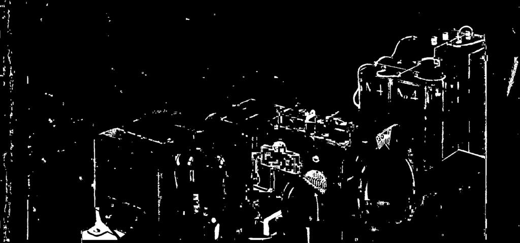
15 PORTABLE POWER UNIT OLD timers will remember the days, some ten years ago, when a portable receiver was really not portable unless an auxiliary crew of six men were required to carry the batteries. Those who were fortunate enough to possess a car, could not afford the space required for additional passengers -the batteries took up so much room. All this is now changed. A.C. operated receivers dominate almost every home in the metropolitan areas, and with the addition of the portable power unit pictured below, they are soon to envelope the portable field as well. As may be seen by referring to the photograph, the unit is so designed that it may easily be carried on the trunk rack provided at the rear of the car -out of the way of any and all passengers that may be in the car. Operated from a separate gasoline engine, the device is designed especially for public address work where a relatively large power consumption is required, although it may be used for ordinary radio receiver operation in conjunction with phonograph equipment. Because of its unique power supply, the device operates independently of the car battery. NEW "MIDGET" SET MIDGET receivers have so long dom inated the radio field in this country I about two years -which is long for the radio industry) that it is difficult to conceive of any radio manufacturer now producing receivers without at least one midget in his line. Let's see what England says. Illustrated below is a new model English radio set exhibited at the recent radio exhibition held at Olympia, England. Note, in particular, the diminutive size of the tubes, coils, wire, etc., by comparing them with the men in the foreground. Don't worry, though -it's only a model! New portable power supply unit. BEGINNING with this issue of RADIO - CRAFT the editors will attempt to bring before its readers the latest devices and advances used in foreign countries. It is hoped that by this procedure, readers will gain a better insight into the advances made in foreign countries, and thus will be better fitted to judge American standards. This month, we start with Germany. Pictured below is a new receiver manufactured by Telefunken, of Germany. Now, this receiver has many good points which may well be incorporated in American sets. First, the under -chassis view, shown to the right of the set, is so constructed as to make servicing a relatively easy matter. This, of course, is in direct contradiction to American standards. WANTED I WE are interested in publishing unusual experiences of our readers in radio reception. If you get unusual DX reception, or if you live in one of those unusual locations where you can pull in almost any station, we would like to have your letters for publication. We are also very much interested in receiving letters from those who receive foreign broadcasts, particularly trans -oceanic reception. All such letters published, will be paid for at regular space rates. EDITOR. NEW GERMAN DEVELOPMENTS Another feature is the fact that the bleeder resistor is made in one long strip consisting of individual components mechanically held together. In the event that one part of the strip goes -it does not become necessary to replace the entire unit. And, each and every part of the strip has its value marked on it, so to avoid useless looking through "parts lists" in order to find the value of the defective unit. Parta lists are provided for replacement work, of course. The "midget" receiver by -. The tuning dial is especially unique. The extreme right -hand photograph shows it. Besides having a velvet vernier dial, all stations are marked on the dial to prevent confusion when tuning for stations. New Telefunken receiver. Under -chassis view of the receiver. Here's a tuning dial that's not a toy. RADIO -CRAFT for NOVEMBER,


16 ELECTROMAGNETIC MUSIC An interesting description of the manner in which a new musical instrument produces a wide range of frequencies without the use of vacuum tubes. By E. E. KASSEL* Fig. A Photograph showing the "works" in the larger model instrument. Fig. a The size of the "Gnome" may easily be estimated from this picture. EXCITER SUPPLY i A Lr INDIVIDUAL PICK -UP MAGNET w SEAMLESS BELT,. J EXCITER COIL G KEY DUALITY \ 111,\ r, I. K 1 METAL TOP BENCH VOLUME / PEDAL " ry1' -r_ AMPLIPIER OR RADIO SET Fig. 1 A sketch Illustrating the principle of operation of the "Gnome." ANY types of electric organs utilizing vacuum tubes and curious circuit arrangements have been built, operated, and de- -cribcd in this and other publications. These instruments have all had some inherent faults such as poor tuning, limited pitches, limited qualities, cumbersome equipment, high cost of production, inability to collaborate with an orchestra because two or more instruments cannot be successfully synchronized, and many other bad features which have so far hindered progress in this line. It is the belief of Ivan Eremeeff, Russian physicist with laboratories in this country, that the above mentioned difficulties may be obviated by employing a combination of phonic wheels and an electromagnetic system to generate tones. Such a system would not be subjected to the eccentricities of systems employing vacuum tubes. As a result of this contention, two types of musical instruments have been developed and are illustrated in Figs. A and B. The larger instrument, shown in Fig. A, is a synthetic type, operating on principles involving the synthesis of fundamental frequencies with harmonic, sub -harmonic, multiple, and fractional frequencies, for the production of musical tones of predetermined pitch, volume, and tone quality. In addition to the numerous different tone qualities, various tonal effects are produced with the aid of a novel keying system. As shown in the photographs and in the sketch of Fig. 1, the keyboards consist of stationary metal keys which are sensitive to the touch of the fingers, the greater the pressure, the better the conductivity, and the greater the volume of the output. The pitches of the keys are in accordance with standardized piano keyboards, and therefore, anyone skilled in the art of playing a piano or organ can shortly adapt himself to the operation of these instruments. Theory of Operation The many different tonal effects created by the various keying touches resemble certain known musical sounds as well as many new and heretofore unknown musical effects. The effect of plucking on a stringed instrument; a piano effect, produced with the aid of a tone -diminishing device; an organ effect, in which the tones are carried out as long as the hands remain on the keyboard; a staccato effect; Mechanical and Photoelectric Instrument Laborut, Iries. a light flute effect; a slur effect, and others are among the many tonal variations available with a keyboard of this type. The source of the tones in these instruments is a series of multi -toothed phonic wheels of the magneto type, and their cooperative adjustable iron core magnets as illustrated in Fig. 1. Referring to the figure, a pulley E, driven by a belt F, rotates a tooth wheel D, placed directly under a pickup magnet C, which is excited by an exciter coil B. As a result of the changing magnetic flux, an EMF is generated which is directly proportional to the speed of the wheel, the number of teeth, and the size of the pickup magnet C. The pitch or frequencies of the voltage generated depend, of course, upon the speed and number of teeth in the wheel D. The phonic wheels placed upon shafts which revolve by pulleys of different diameters and at different predetermined speeds, according to the frequencies of the pitches of a musical scale, collaborate with their magnets for producing tones of different pitches. These tones are then fed into an ordinary radio amplifier, and then, of course, to the loudspeaker. The smaller instrument has been called a "Gnome" and works on the same basic principles as employed in the larger type of instrument described above. However, while the large type obtains tone peculiarities by the accurate synthesis of different frequencies at different intensities, the "Gnome" produces tone quality with the aid of a dial wave- alteration control, in which wave forms are modified by the selective connection of the output circuit to different taps of a transformer, or by a system of condensers which are adjusted by a dial. In both cases, however, the performer Is seated upon a bench which has a metal top to which the circuit of the instrument is connected, the body of the performer acting as a conductor to the metal of the keys, the sensitivity of the touch of the fingers determining the effect of tones, as previously described. A rather novel feature introduced by these instruments is the new method of music writing, including the accurate scientific delineation of curves representing wave forms, in place of ordinary notes and symbols as used in ordinary music writing today. These new methods correctly indicate pitch, by frequency numbers; vol- (Continued on page 297) 270 RADIO-CRAFT for NOVEMBER,


17 A CHURCH SOUND SYSTEM By KARL DOBESCH, Berlin View showing the band microphone in front of alter. ST. STEPHAN'S CATHEDRAL OF VIENNA, a marvel of Gothic architecture, was handicapped by poor acoustics. Its magnitude made it virtually impossible for the preacher to be heard throughout the nave, inasmuch as the high - towered curved ceiling, through its multiple echoes, drowned the words. In the presentation of ecclesiastical music, the distance of 100 meters (330 feet) between the main altar and the big organ manifested itself unpleasantly by the elapse of 1/3 of a second which the sound requires to overbridge the distance, thus causing considerable difficulty in the way of timing the music and the choirs. In order to do away with these deficiencies, the chapter of the cathedral tried to bring about improved acoustic conditions by appropriate measures. The task in question was fulfilled completely. After numerous acoustic experiments which were undertaken, it was found that an installation of eleven electrodynamic loudspeakers was necessary. The placing of the speakers was made, keeping in mind that there should be an equal amount of sound energy in the northern and southern transepts and in the side aisles. Several loudspeakers had to be especially shielded to suppress echoing. In installing the loudspeakers, not only was the attainment of the best possible acoustic qualities a main factor, but it was also necessary to set them in the least conspicuous places, so as not to disturb the architectural beauty r of the interior in any way. Apart from the small dimensions of the loudspeakers, this requisite was fulfilled by a coat of stone -gray paint. Built in the ornaments and carvings of the pillars, in the altars and in the chairs of the choir, they are practically invisible in the dim light of the cathedral. (Continued on page 298) Note the placement of two speakers, one located over a Maria Poetsch. painting of Another speaker placed at the southern part of the church. near a monument of Emperor Frederick III. RADIO-CRAFT for NOVEMBER,


 in that they did not require a")


18 THE VELOCITY MICROPHONE All of the microphones developed and used in the past utilize, for their action, the pressure variations of the impressed sound. In this latest development, the action of the microphone depends upon the velocity of the impinging wave. By J. P. TAYLOR* Fig. A An excellent photograph illustrating the assembly of the Velocity Microphone. The three permanent magnets support a magnetic frame between which the corrugated, duraluminum strip vibrates, as shown above at the top. FROM the early days of broadcasting, the studio microphone has presented the hardest problem engineers have had to meet in their constant efforts to improve broadcast fidelity. Early carbon types were unreliable and of poor quality. They were improved upon -but were never entirely satisfactory because of their high background noise and susceptibility to blasting. Meanwhile, speech input and transmitting equipment capable of reproducing faithfully the range of frequencies from 30 to 10,000 cycles had been developed. A microphone of equal range was imperative. The condenser microphone was the answer. Transmitting with fair fidelity the entire range, it presented a real advance and soon became an accepted standard. Recently other types of microphones have been introduced. These have had about the same characteristics as the best condenser microphone but have had an advantage (under certain circumstances) in that they did not require a closely linked amplifier. Despite the 30- to- 10,000 -cycle range of the condenser and other recent types of microphones, they did not satisfy the more discriminating engineers. The frequency curves by which they were judged were fairly flat -but they were made by the actuator method. In this method of calibration, the pressure of the sound wave is simulated by a vibrating rod exerting a mechanical pressure on the dia- phragm of the microphone. Engineers were openly doubtful of the veracity of this method -they thought they could detect in the reproduced signal whistles and lisps which could be due only to the un- natural accentuation of certain frequencies. They decided to check it by the Rayleigh disc method. A pure sound wave of known frequency and amplitude is generated by the Ray- leigh disc. Since this is essentially a sound wave in free space, it makes possible very accurate measurements of microphone response. As these engineers expected, these measurements showed all available microphones to have various peaks and dips. Having proved this, they had no difficulty in determining the reason. All the microphones used up to this time employed a diaphragm which offered a relatively large and impeding surface to the passage of the sound waves. These waves were reflected by this surface and hence the pressure on the diaphragm was (Continued on page 299) Transmitter Salem Engineer, R. C. A. Victor Co., Inc. Fig. B An illustration of the flexibility possible in placing the artists with the new microphone. In the older types, it was necessary for all the artists to face the front of the microphone, but with the Velocity microphone, the artists may be anywhere around it. _I.12 m NO U +a Li o Z oo + 2 w 2 CC N Z 4 Z O F 6 K-10, 12 6O `-,1 DYNAMIC CONDENSER MICROPHONE Il/e112 man VELOCI I0p00 20p00 FREQUENCY IN CYCLES PER SECOND Fig. 1 Curves comparing the condenser, dynamic and velocity microphone,. 272 RADIO-CRAFT for NOVEMBER,
 10 V. 'oh5 MS SO0,D 50 400E1600 50 1 i /00V. C00- AMPERES `OiwÉ4. o.oño 250V. 3% G.,5 500 5O0 V. N.s- EG. WV( 4 VLMA, 1ß00V. 4.84 0 (\"'1'Mw_ 75 1 d - omms,0 '252.")


 DRIVING NOD TIP SACK Above is a completely assembled, and below a dismantled view of the crystal microphone.")
19 ANNOUNCING THE WESTON 663 VOLT -OHMMETER By L. VAN DER MEL GES, p OHMS -MA. I MA OHMS 5 MA 84.2 OHMS 25 MA OHMS 100 MA 5.26 OHMS eT0M-R X10 -ozs,pts ê =MA..0.4 The new model 663 volt -ohmmeter. 1.5V OHMS, 7,500 OMMS -'i1l1bl.l1l8_,5.5t) 10 V. 'oh5 MS SO0,D E i /00V. C00- AMPERES `OiwÉ4. o.oño 250V. 3% G., O0 V. N.s- EG. WV( 4 VLMA, 1ß00V ("'1'Mw_ 75 1 d - omms,0 '252.5 XI OHMS Mo V ma. C x1omo O Ms RIO +5 o.wo X MEANS ID LY MS V MEANS THOUSAND Schematic circuit of the new model 663. THE Model No. 663 volt- ohmmet e r illustrated here has been designed to answer the demand for an ohmmeter capable of measuring both very low and very high resistances. The voltage and current ranges have been added to make this instrument as universal in its application as possible. This instrument should really be considered as a volt - ohmmeter, the current ranges simply adding to the usefulness of the device. The circuit (shown here) has been built onto a molded black bakelite panel of the same style and dimensions as the panel used in the Model No. 660 described in the September 1932 issue of this maga- zine. In appearance, the 663 is exactly similar to the 660; the panel is complete as a unit, no parts being mounted in the case itself. The meter used in the 663 is a Model 600 microammeter, having a full -scale sensitivity of 50 microamperes. This sensitivity is required for the higher resistance ranges. A very small diameter tubular pointer on the meter with a knife edge tip is also used. This is the same pointer as is now being used in the Model 301 instrument in the 660 Analyzer. An etched scale, showing 0-1,000 ohms above, and volts and milliamperes below the arcs, is supplied. Energy for the ohmmeter ranges is supplied from self- contained batteries. Three Burgess No or Eveready No. 781, and one Burgess No. 2 Unit Cell or Ever - eady No. 950 Unit Cell are required. These batteries fit into clips mounted on the rear of the panel where they are accessible by removing the panel from the case. A twenty -four position, one -deck switch is mounted under the panel in the same manner as the switch is mounted in the 660 panel. This switch is arranged to operate through eight positions only, giving seven ohmmeter ranges and one position both for "Volts and Milliamperes." Battery -voltage compensation is obtained by the same arrangement as used in the Model 660. The control knob is located in the same relative position and appropriately designated "ohmmeter adjuster." Seven tip jacks are used on the upper left hand side of the panel for the six voltage ranges. These jacks are of the same style as used on the Model 660 and are connected to the meter only when the switch is in the "Volts- Milliamperes" position. All voltage ranges are on the basis of 1,000 ohms per volt -a recognized voltmeter sensitivity for all classes of vacuum -tubes popular in other fields. (Continued on page 297) DRIVING NOD TIP SACK Above is a completely assembled, and below a dismantled view of the crystal microphone. THE CRYSTAL the opposite page is illustrated and ON described the "Velocity Microphone," which shows promise of invading the sound field to no small extent. Previous issues of this publication have carried descriptions of the crystal loudspeaker, and mention was made of a crystal microphone. At the left is illustrated a new type of unit utilizing the same principles as the crystal speaker -the crystal microphone. Housed in a heavy, black, metallic shell, as illustrated in the upper part of the photograph, it represents a very decided advance in microphone technique. A view illustrating the component parts is shown in the lower part of the photograph. Construction The assembly of the microphone is very simple. The two plates of the crystal are mounted, sandwich -like, near the terminal end as shown. One edge of the crystals is cemented to the shell, leaving the other end (the crystal is wedge- shaped) free to MICROPHONE vibrate. The drive rod is attached to the free end. ' The diaphragm is cone shaped, and its apex is rigidly attached to the drive rod mentioned above' Contrary to, the conventional diaphragms used in microphones, the type made use of in this construction is of impregnated, soft card- board. In this 'manner, metallic rattles are done away with; critical annealing'and stretching is entirely eliminated; and: the diaphragm may be dismantled for inspection without any fear of it not functioning properly after it is put together again. Using the Microphone The advantage of the unit is the fact that it may be connected directly into the grid and filament of a tube without anÿ; transformers of any sort. The volume control for the unit may be connected directly across the microphone terminals. Of course, if the leads from the microphone to the amplifier are to be very long, a transformer between the "mike" and the line is recommended. RADIO -CRAFT for NOVEMBER,


20 HOW TO BUILD AND OPERATE A UNI -DIRECTIONAL LOOP ADAPTER FOR THE BROADCAST FAN O aríi By C. W. PALMER Fig. A Fig. _, 1 I --,. /,_ s Í --, _ \, i, l... -A- /:-,- 7_\ f- re \\,/\ \ i i.11---,, i i 1 {1 J 1 / J -- _ ` íí-=:. '\ =' /, I t \ \ \ _\ \\ / Flo. 3 LOOP FFI ELD INTENSITY LOOP -C- A B SOME time ago, the Aeronautical Branch of the U. S. Department of Commerce issued a bulletin in which an advanced type of direction finder was described. In this direction finder a single, small loop -aerial is employed. It gives the direction of the transmitting station and also the sense of deviation of the line of flight of the airplane from this direction. With these facts in mind, it occurred to the writer that such a unit could be used to advantage for broadcast reception, when it is desired to employ a loop. In the first place, no special input circuit for the broadcast set is necessary as the loop unit is merely connected to the aerial terminal of the broadcast receiver; and, in addition, the best point of reception for the loop for a particular station is indicated by visual means, through the use of a zero -center pointer type of mil - liammeter. so much for the advantages of the loop; let us now consider the method of operation of the device. Suppose that we have two loops connected in series as shown in Fig. 1. Terminal B is the mid -point of the two loops and connects directly to the aerial post on the ' receiver. The ground post of the set is connected to A, terminal C being open. Under these conditions only loop No. 2 is in operation. If, now, terminal C is connected to the S D \.- \ FIELD,` 150f >'"7' NTE ISITY fï \ ' j Y 7 \\\ 165J /\\ ` \J /'..1\%tl i i -' I \\I 1 1. I fi 1 t\ \ % 1 \ --iji\\.../l% \\\ \-- i \\- / \--i i / \ i / AERIAL s Loóp\ Fig. 2 Field pattern for an ordinary loop. set instead of terminal A, then loop No. 1 would be operating; the only difference being that the phase of the signal would be shifted 180 degrees -a matter of small importance. If an automatic switch is connected in the circuit that would use loop 1 for a fraction of a second and then switch to loop 2, and if the loops were correctly connected, the net result in the loudspeaker would be the same as if only a single loop were used -except for the small break in the signal due to the time taken in switching from one loop to an- other. Exactly the same results may be obtained by using a single center -tapped loop as in Fig. 1B. The adoption of the single loop aerial to direction finding purposes utilizes the distorted field intensity pattern which results when the loop is not symmetrical with respect to the ground. The field intensity pattern for the reception of a transmitted wave by a loop -aerial is normally in the form of a figure -of- eight. (See Fig. 2.) Lack of symmetry of the loop -aerial with respect to ground may result in any of the distorted forms shown in Fig. 3. The cause of these changes is the vertical effect (in other words, the loop operating as a simple vertical aerial) and the phasing of this current With the normal loop- antenna current. Fig. 4 Coordination of two loop patterns. 274 RADIO -CRAFT for NOVEMBER. 1932


21 An ordinary loop cannot be used with a broadcast receiver because of ganging and additional tuning difficulties. With this circuit, the loop may easily be adapted to any receiver and has uni- directional response characteristics. Fig. B When the loop -aerial is tuned to resonance with the frequency of the signal being received, and the ground is displaced so that the vertical effect is present, the current due to this vertical effect is 90 out of phase with the normal current in the loop aerial. This gives the effect shown in Fig. 3A. If, however, the loop is not resonated, the current due to the vertical effect is in phase with the current in the loop and the patterns of Fig. 3B or 3C results, depending on the relative amplitude of the current due to the vertical effect and that due to the loop- aerial. It is this distorted field pattern that is utilized to provide the direct - reading indication of the direction of the transmitting station. The Two Field Patterns Refer to Fig. 4. This shows the coordination of two wave patterns on opposite sides of the center tap of the loop; that on one side being indicated by the full lines, and that on the other by the dotted lines. The completed field pattern is then indicated by the composite diagram as shown. If the signal comes from direction C, the voltage induced in the loop from either of these patterns is equal (O to A). If, however, the signal comes from the direction Cl, the voltage received on the loop for pattern Y will be equal to O -Al which is greater than that for pattern X, namely O -A2. Suppose, now, that the signal comes from direction C2. The received voltage for pattern Y, that is, O -A3 will be much less than that for the pattern X or O -A4. Thus it is readily seen that if some means is secured for measuring the relative intensity of these two signals, not only can the direction of the transmitting station be determined, but also the sense of deviation can be estimated. Let us see, now, how these field patterns may be utilized for direction find- ing. Consider the loop pattern of Fig. 3C. Due to the vertical effect, the response of the loop to the left of the cen- AERIAL L B SPEAKE R /r I - I ter is greater than that at the right. This means that if a switching arrangement were provided to alternately use terminals A and C, and if at the same time a D.C. milliammeter is connected across the loudspeaker terminals, and its connections reversed in synchronism with that of the loop terminals, the D.C. milliammeter will always read in one direction. For instance, refer to Fig. 4. A signal from C2 generates a voltage O -A4 due to pattern X and an opposite voltage O -A3 due to pattern Y; the average is some value between the two. It no switching took place, the milliammeter or galvanometer would read zero always, but if the loop terminals and the galvanometer terminals are switched in synchronism, the meter will always read to the left. The unit that does the switching is called the synchronizing unit, and that circuit in which the milliammeter or galvanometer is connected is called the output unit. The schematic circuit (Continued on page 301) C4 M A. RADIO RECEIVING SET f1 7 C5 L 110 V, A. C. sw NV. CHOKE... TO LOOP TO CENTER TAP RADIO SET Fig. 7 Constructional details of the loop. Either a boa or plane type may be used. Fig. 5 Schematic circuit of the Air -Loop unit. The photographs show the location of the parts. Fig. 6. lower right The antenna filter system which is sometimes needed for proper operation. RADIO -CRAFT for NOVEMBER,


22 TRIPLE SHIELD COUPLING CHOKE INTERSTAGE TRANS. FILTER POWER & FILTER BLOCK CHOKES TRANSFORMER, CONTROL UNIT. RADIO PHONO OR CONTROL IN: BAT. OFF TONE A.C. AUTO A.C. BOX OUT: BAT. ON CONTROL POWER UNIT Fig. A Left, the P.A. amplifier and right. its Auto A.C. Supply Unit. The cables for connection to the control box are also shown at the right. A UNIVERSAL P. A. AMPLIFIER By LEON J. LITTMANN,* B.S. in E.E., E.E. SO many uses have been found for public- address amplifiers that it is no wonder that their use has been constantly increasing. While there are many such systems available, they are usually large, costly, and take consider- These short-com- able time to install. ings have prevented alert Service Men. with a small purse, from reaping the benefits which they should undeniably enjoy by renting or selling P.A. installations. RADIo-CRAFT and other publications have, in the past, outlined in detail the numerous uses to which P.A. systems may be put, and therefore any further at- tempts to expound them here would be superfluous. Suffice it to say, however, 276 Chief Engineer, Coast to Coast Radio Cons. 110 V.. A.0 DRY RECTIFIER T 1! t ( 1000 MF. ELECTR N = 6 VOLTS D. C. Fig. 1, right Schematic circuit of the P.A. system and power unit. All values are shown in the diagram. Fig. 2, above Circuit arrangement of the power- supply unit. that the system to be described may properly be termed a "universal amplifier," for the simple reason that it is designed for use either in an automobile or in any stationary location. The amplifier itself, illustrated at the left of Fig. A, is designed to operate directly from a 110 -volt, A.C. source without any additional equipment with the exception, of course, of the microphone or turntable, and loudspeakers, and is capable of delivering 15 watts of undistorted output which is sufficient to supply an auditorium having a seating capacity of about 2,500. Obviously, with reduced volume, it may be used in small dance halls, churches, etc. When the system is to be used in a sound truck and is to be operated from RADIO/ 500 TONE CONTROL MP PACK CM4.? CONTROL Box.5-ME L. BATTERY SW.2 37 p. AMP FUSE TOA B ANO FL ê CI SW / ELECT. 82 5W5 '300T - - SOOy CM.3 SONY. I OHMS 500 OHMS 300V. W l q CHI.` 3014YV I f 1 CN2 `C70yy00M5, IS 110V. C2 A.C. storage batteries, the unit shown at the right of Fig. A is connected between the 6 -volt storage battery and the amplifier. Thus, it takes but a few moments to arrange the system for either portable or stationary work. It should be noted that the tubes may be operated directly from the car storage battery -the only purpose for this provision being to enable the use of an inexpensive 6 -volt auto A.C. power unit. It is clear that such an arrangement results in increased efficiency of the entire system. The Amplifier The schematic circuit of this amplifier is illustrated in Fig. 1. As may be seen, it consists of two type '37 tubes In a push -pull connection, feeding four type 42 tubes in a parallel push -pull connection. The output transformer is designed \- + ir i DNMS r, o( i -^'{ SOKR. SOCKET F2 5%Uf. 'ay 3Mi éoov xsonm HM5 POT. OUTPUT TRANS. for either 33/y, 71/2, 15, or 500 ohm outputs. The u s u a l power supply unit is provided. The amplifier itself is equipped with four switches, SW.1. being in the primary side of the power transformer, P T ; SW.2, being e o n - nected as shown, and when closed, lights the filaments of the (Continued on page 300) RADIO -CRAFT for NOVEMBER, 1932 A


. To a number of readers analyzing capacity circuits, it would appear that resistors are unnecessary.")


23 THE SPECIALTY TESTER A description of an extremely small size tester capable of measuring and testing small and large condensers and resistors. It also incorporates an A.C. -D.C. voltmeter for output measurement work. By JACK GRAND Fig. A Front view of the "specialty tester" with its prods and line cord and switch. i ohms; "M.O." is medium -ohms range of 0-10,000 ohms; "L.O." is low -ohms range of 0-1,000 ohms; "H.OP" is high - output range of 100 volts A.C.; "M.OP" is medium output range of 10 volts A.C.; "L.OP" is low- output range of 1. volt A.C.; "I-LC." is the high -capacity range from 4 to 14 mf.; "M.C." is the medium - capacity range from.1- to 4mf.; "L.C." is the low- capacity range from to.05-mf. The abbreviation for the adjusters is "ADJ "; for the ohms locator "O.L."; and for output capacity "O.C." The ohm and output -meter incorporated in the specialty tester was described in the August issue of RADIO-CRAtT. It is suggested that the constructor have that issue handy for reference. Capacity Measurements To obtain capacity readings from to 14 mf., three current ranges of 1., 100, and 500 ma. will be required (note the low -capacity ranges obtained with this tester). To a number of readers analyzing capacity circuits, it would appear that resistors are unnecessary. Such is not the (Continued on page 303) Fig. B Rear view of the tester illustrating the placement of the parts. T is the odd things in experiments and radio service work that are most annoying to the experimenter and Service Man; that is, the things that even the best of set testers do not seem to locate or provide means for locating. The odd things referred to are: capacity values, resistance, and output voltage. With this thought in mind the "specialty tester" was designed. Compactness a Feature The first consideration was to make the instrument compact and, therefore, portable; the final dimensions being 51.'r x 714 inches. The next problem was to get 33 pieces of apparatus into this space. This was finally accomplished, as may be seen from the photographs of Figs. A and B. Cost was another consideration; it Note its small size. had to fall within the financial means of everyone, and yet use standard, easy -toget parts. The parts as listed (basing the cost at recognized wholesale prices) amount to approximately $ This includes a drilled and engraved panel. Most of the up -to-date testers incorporate some of the features of the "specialty tester" -the older types, practically none. In any case, the use of the measuring features of the specialty tester in a set analyzer is sometimes rather inconvenient. The capacity, resistance, and output voltage ranges each have three calibrated scales, and the selection of any range is made via a four -pole, nine -throw switch. All readings on the panel are abbreviated as follows: "H.O." is high ohms (means "high resistance ") range, from 0-100,000 Fig. 1 Schematic circuit of the tester. RADIO -CRAFT for NOVEMBER,


24 A UNIVERSAL ANALYZER ADAPTER A description of a unique device capable of facilitating the measurement of all tube voltages and currents. By HERMAN BU BLITZ Above external, and below, internal view of the Interesting analyzing adapter. T HE ever increasing number of new tubes and their varied applications make it difficult for the modern Service Man to keep abreast of the times with his testing equipment. When the type 57 and 58 tubes came out, the writer found it necessary to bring his equipment up to date. Fig. 1 Schematic circuit of the adapter. CAPS ON HANDLES TUSE SASE ARE SHOWN BOTTOM SIOE UP Six PRONGS SEVEN PRONGS -C- -B- -D- D O TO TIP MINUS JACK WAS 1.V. r -_ 9 o v - To TIP PLus JACK Ne 12 Fig. 2 Details of connections of the cables. Having an A.C. -D.C. voltmeter, it is simple enough to take voltage readings right at the sockets, but when current readings are to be taken, well that's another story. In order to overcome this difficulty without spending a small fortune for a new analyzer, the adapter, herein described, was built. It enables one to take all voltage and current readings at the tube sockets; allows all tube connections to be opened for the purpose of inserting phones for audible testing, or for the introduction of signals on the grids of tubes by means of a pickup, an oscillator or the antenna. With the addition of one or two 4.5- volt "C" batteries, tubes may be tested for mutual conductance right from the set. They may also be tested for shorts with any continuity tester the Service Man may have. Description of Tester As may be seen from the photographs, the adapter consists of a box of suitable size and three cable extensions with their necessary tube bases and multiple connectors. Three separate cables were chosen in order to obviate the necessity for numerous small tube adapters, which are easily mislaid, and which have a hab t of remaining in the socket of the se, Fig. 3 Details illustrating the construction of the plug handles. making it sometimes difficult to extract them when testing the chassis. No exact constructional measurements are given here, since the adapter may be built to suit ones own idea. It may even be incorporated with a multi -scale voltmeter and ohmmeter in one case, constituting, in this fashion, a complete service unit. The tip jacks recommended come in pairs, one red and one black. Thus, seven red and seven black ones are used. Mount them in the following order, referring to Fig. 1. Jack Nos. 1, 2, 3, 4, 5, 6, and 10 are black; Jack Nos. 7, 8, 9, 11, 12, 13 and 14 are red. This places a black one (No. 10) in a row of red ones. Since this is the cathode, all voltages are measured from No. 10, except in the case of UX tubes. (The cathode, of course, receives the negative meter prod.) When grid -bias voltage is read, then the cathode receives the positive meter prod. In the first row, jack No. 7 is red, the others being black. This jack is used solely for the insertion of a length of wire, about 6 to 8 incites long and containing at the free end a tube clip, to be used when testing screen -grid tubes. Mount the switches (D, E, F, G, H, and I in Fig. 1) all in one direction so the operator can readily tell whether they are open or closed. Since the tip jacks are of the insulated type, a metal panel and wafer sockets may be used. The multi -plug extension may be fastened on either side or end of box. In constructing the cable extensions, it is advisable to use a very flexible cable with a rather loose braiding around it. As will be seen, the cable has a UX base and contains five wires, thereby permitting the testing of '22 and '32 types of tubes. In order to construct the tube -base handles, secure three hardwood file handles having a diameter of 11 inches, saw both ends off and drill a ai inch hole all the (Continued on page 304) 278 RADIO -CRAFT for NOVEMBER, 1932


25 RADIO -CRAFT KINKS Practical Hints From Experimenters' Private Laboratories Prize Award A CODE -PRACTICE ADAPTER By Joseph X. Reilly FINDING it necessary, recently, to build up an instrument for code practice, the idea occurred to the writer to use a dynatron oscillator as the source of the note. A simple instrument was then constructed, illustrated in Fig. A, following the recommendations of Don Hale, in the August, 1932 issue of Electronics magazine, pg In the screen -grid tube circuit described by Mr. Hale, there exists not only a dynatron- oscillator action at Fig. A An ultra- modern code -practice set. Fig. B A power resistor for replacement work. Fig. C This idea is n it as wet as it may appear. $5 for a Practical Radio Kink As an incentive toward obtaining radio hints and experimental short -cuts, "Radio - Craft" will pay $5.00 for the best one submitted each month. Checks will be mailed upon publication of the article. The judges are the editors of "Radio - Craft" and their decisions are final. No unused manuscripts are returned. Follow these simple rules: Write, or preferably type, on one side of the sheet, giving a clear description of the best radio "kink" you know of. Simple sketches in free -hand are satisfactory, as long as they explain the idea. You can send in as many kinks as you wish. Everyone is eligible for the prize except employees of "Radio- Craft" and their families. This contest closes on the 15th of every month, by which time all the Kinks must be received for the next month. Send all contributions to Editor, Kinks Department, c -o "Radio- Craft,' 98 Park Place, New York City. audio frequency, but also a variable -frequency characteristic; the novel feature is that the periodicity is under the direct control of a filament rheostat, Rl in Fig. 1. The two clips on the leads of the "B" cable, shown in Fig. A, may be connected directly to a "B" battery supply of about 110 V., or they may be connected into a radio receiver at a point along the voltage divider where this voltage may be derived. The phones constitute the A.F. resonant circuit. In some instances it may be desirable to bypass the high -voltage supply by a condenser C of about 0.1 -mf. Resistor R3 establishes the maximum potential applied to the filament. A SIMPLE LABORATORY RHEOSTAT By F. R. Harris I DON'T know how many of you fellow experimenters have discovered the fact that the replacement elements sold for use in the bowl type of electric heater make most excellent power resistors; but for those who haven't, my tip is: give them a trial. They have a resistance of around 18 or 20 ohms, their power dissipation capacity is very high, 600 watts or so, and properly mounted away from inflammable material one need not worry about temperature rise -they are designed to operate at red heat. These elements are made in two general types; those with a standard screw base and those with a band of brass at each end which is fastened to terminals with screws. The former type can be mounted in porcelain sockets and wired in any desired series or parallel combina- tion; the latter type may be mounted on a spindle supported between trunnions and variation in the resistance is then conveniently obtained by means of a contact arm, as shown in Fig. B. A knob is provided for rotating the spindle. About the only critical dimension on the whole job is the length and settin,; of the swinging arm. If made too short or set incorrectly it will bind and jump upon rotating the variable element. The recommended length is 31/4 ins.; the best setting is easily determined. The wiring diagram, Fig. 2, shows that the unit may be so connected as to use a fixed resistor only, screwed into the socket; the variable resistor alone; or both in series. CORRECTING A REMOTE PICKUP FAULT By A. P. D'Ambria RADIO broadcasting problem was re- cently solved when station KFKU of the University of Kansas offered two lessons in swimming -via radio. In order to add realism to the broadcast, the director of programs conceived the idea of having the performers not only dress in appropriate costumes, but actually go through the motions in a pool during the instruction. Accordingly, the microphone was moved to the varsity swimming pool, as shown in Fig. C. A rehearsal of the broadcast brought out the fact that conversational tones echoed and re- echoed throughout the enclosure. Various schemes to correct this condition were tried -without success. A happy solution to this problem finally was found in the use of a canvas canopy over the pool. This not only eliminated the echoing but concentrated the "splashing" and "paddling about" of the pupil and added realism to the broadcast. Fig. 1 Schematic circuit of the code -practice set. t- 911 FANNE STOCK CLIPS s (MP uu FIXED RESISTOR / VARIABLE RESISTOR i Fig. 2 Wiring diagram of the replacement power unit. RADIO-CRAFT for NOVEMBER,
G011, Ht H G FIG.37 FIG 36 o G O P G F- O FIG. 39 +-CONTROL - GRID CLIP O F- F+ H H FIG.")


26 G P G P O 0 F- 9 F+ 0 0 G P O i O F+ P r 0 C O N S T R U C T I N G ADAPTERS FOR A C FIG.30 P PHONE TIP JACK P K K F- F+ F- F+ FIG.31 FIG.32 PHONE JACK 63 H H H H HW -H FIG 33 FIG.34 FIG.35 CONTROL-GRID STUD B00 i OHMS Q O -- O O ß O 0 O 00P 0 I 0 )G011, Ht H G FIG.37 FIG 36 o G O P G F- O FIG CONTROL - GRID CLIP O F- F+ H H FIG. 41 E O G Pb bp 0 0 F+ CONTROL- - GRID STUD G O G P o P F- F4 FIG. 42 By F. L. SPRAYBERRY* TR"ENTY -NINE out of one- hundredeighteen adapters have been described in the October, 1932 issue of this magazine. The adapters as described are suitable for use with Jewell analyzers. In this issue, we complete the list of adapters for use with Jewell analyzers, and proceed, next month, with a description of adapters designed for use with Weston analyzers. Following this, will be a description of the adapters required for other standard makes of analyzers. No. 944BRA, Fig. 30, is used with set analyzers in connection with adapter No. 944 BRB. This adapter permits the plate - current reading of the BR rectifier tube. No. 944BRA is placed in the eliminator socket while No. 944 BRB is placed in the analyzer socket. A four -prong plug, or any other plug with the proper four - prong adapter is then placed in the No. 944BRA adapter. May be used with Jewell models 117, 133, 133A, 137, 198, 199, 408, 409, 464, 577, 578, 579, 581 and 660. No. 944BRB, Fig. 31, has been described in connection with No. 944BRA. However, this adapter may also be used in tube checkers if a proper current -limiting resistor is used, or if the plate voltage is low enough to prevent a high plate current. No. 944B1IR, Fig. 32, is used to test the Raytheon BA and BH tubes in tube check- ers. The adapter is placed in sockets which test the '80-type tube. May be used with Jewell modela 209, 210, 214, 533, 534, 535, , 540, 597, and 675. If desired, these adapters may be used in pairs in connection with set analyzers to give the regular plate- current reading as obtained from the eliminator circuit. Place one adapter on the test plug and G 0 G O Service Consultant, National Radio Institute, Washington. D. C. 6" PEAD L. P O I F- F+ FIG.43 CLIPS P F- F+ G P F- F4 FIG.44 G" LEAD F CONTROL GRID STUD K H G H 4'/1 FT. LEAD the other in the analyzer socket. May be used with Jewell models 198, 199, 408, 409, 444, 531, 566, 577, 578, 579, and 581 set analyzers and test panels. No. 955KPT, Fig. 33, is used for connecting an output meter across the plate and screen -grid of pentode tubes. May be used in connection with the Jewell 559 output meter or the Jewell 444 and 660 set analyzers. No. 955SPT, Fig. 34, is for connecting an output meter across the two plates of a triple -twin tube. May be used in connection with the Jewell models 444, 559, and 660. No. 965KS, Fig. 16, is also used to test the 89 tube in tube checkers. It is to be placed in the regular '37 socket of tube checkers. May be used with Jewell models 210, 214, 533, 534, 535, 536, 538, 540, and 597. No. 975KP, Fig. 35, is used to teat seven - prong tubes. May be used in any tube checker having a five -hole socket. Used with Jewell models 209, 210, 215, 533, 534, 535, 536, 538, 540, 597 and 675. No. 950HS, Fig. 36, is a combination adapter employing four different sockets fitted to a basic five -prong base. With this adapter, the 29, 69, 41, 42, PA, PZH, 57, 58 and 82 tubes may be tested from screen - grid sockets of the five -prong type if wired for 2.5 and 6.3 volts. This adapter will also be available with a seven -prong socket so that the new seven -prong tube may be tested. May be used with all Jewell tube checkers and any other type having a 2.5 volt and 6.3 volt, five -hole socket. No. 421X, Fig. 37, is used on the plug for its UX adapter) of any Jewell analyzer for plugging into WD -11 sockets. This adapter is used with No No. 968, Fig. 38, is used on the UX CONTROL - GRID CLIP FIG. 45 7" LEAD H H F- F+ H H FIG. 45 A G P 280 RADIO -CRAFT for NOVEMBER, 1932


27 In this second part of a series of articles, details of an additional thirty -three adapters are included. TEST EQUIPMENT GRID CLIP GRID CLIP G F+ FIG.61 FIG.62 F- G G G socket of any Jewell analyzer to hold the WD -11 tube. No. 999, Fig. 39, is used on the UX analyzer plug or its UX adapter to permit its insertion into UV 199 sockets. This adapter is used with the No. 429 plug. No. 429, Fig. 40, is used in the UX socket of any Jewell analyzer for receiving the UV199 tube. No. 954DD, Fig. 41, is a twin adapter for use with Jewell model 137 so that analysis of '24, '35, '36, '38, '39, '44 and '51 tube circuits can be made. No. 419X, Fig. 42, is used with any Jewell UX plug or its UX adapter for insertion into UV -type sockets. This adapter is used with No No. 967, Fig. 43, is placed in the UX socket of any Jewell analyzer to take the UV type tubes. No. 949K, Fig. 4, is used with the UX plug or its UX adapter to analyze the circuits of overhead heater type tubes. This adapter is used with the No. 944LS. No. 944LS, Fig. 44, is used with any Jewell analyzer to take the overhead heater type of tubes when analyzing their circuits. No. 955DGLC, Fig. 45, is used with the Jewell models 198 and 199, old series, to analyze the circuits of the first section of the Triple Twin tubes. This adapter enables all readings to be made by reading the analyzer directly. No. 955DPP, Fig. 46, is used with the Jewell 198 and 199, new series, 408, 409, 444, 531, 566, 577, 578 and 579 to analyze the circuits of the first section of Triple Twin tubes. This adapter makes possible the direct reading of the analyzer. No. 954DP, Fig. 45A, is used with the Jewell 198 and 199, old and new series, 408, 409, 444, 531, 566, 577, 578, and 579 to analyze the second section of the Triple - Twin tubes, making all readings direct as CATHODE STUD G noted on the analyzer. No. 955GGKC, Fig. 47, is attached to the five -prong analyzer plug or its UY adapter on models 137, 198 and 199 old and new series, 408, 409, 444, 531, 566, 577, 578, and 579 to analyze the circuits of the five - prong Wunderlich tube. No. 955GGKL, Fig. 48, is placed in the UY analyzer socket and the five -prong Wunderlich tube is inserted in the adap- ter. It is to be used with the No. 955GGKC above for set analysis of the five -prong Wunderlich tube. No. 975DD, Fig. 49, is used with the Jewell models 198 and 199, old series, for socket analysis of the new seven -prong power amplifier tube. No. 975DW, Fig. 50, is used with the 198 and 199 new series, 408, 409, 577, 578 and 579 analyzers for analysis of the seven -prong tube circuits. No. 975DSW, Fig. 51, is used with the 444, 531 and 566 analyzers for analyzing the circuits of the new seven -prong tube. This adapter is similar to the No. 975DW but has a locking stud to engage the latch in the analyzer plug. No. 945GL, Fig. 52, is used with the model 566 analyzer being attached to the four -prong adapter of the analyzing plug for analysis of the 33, 46, 47, GA, LA and PZ tube circuits. No. 954GL, Fig. 53, is used with model 566 analyzer, being inserted in the UX socket of the analyzer to receive the pentode tubes in above analysis test. No. 968R, Fig. 54. is used with Jewell models 209, 214, 533, 534, 535, 536, 538, 540 and 675 for checking the WD -11 tube in the '26 socket. This adapter has a resistor to drop the filament voltage from 1.5 to 1.1 volts. No. 944R1, Fig. 55, is used with above Jewell models for checking the 864 tube (Continued on page 309) CATHODE - CLIP G G3 F- "F+ F- F+ F- F+ FIG.58 FIG.59 FIG.60 G P G P G F- F+ F- F+ H ih FIG.55 FIG.56 FIG 57 CONTROL-GRID 1HONE CLIP TIP p 2.2 K 0Hm5 F H H F- F+ F- F+ FI G. 52 PHONE TIP G5 G G2 p P FIG.53 F G.54 6 "LEADS LOCKING STUD IN CENTER OF SOCKET K ` 4'/2 FT LEAD K FIG. 51 6" LEADS G GRID CLIP o RADIO -CRAFT for NOVEMBER,


28 SOLDER ENDS OF LOOP HERE 13 TURNS HE 18 WIRE CLOSE WOUND FIBER STRIPS FLAT HEAD BRASS SCREWS SHORT CUTS IN RADIO SERVICE DRILL HOLES ON SLANT SO WIRE WILL NOT BE EXPOSED WHEN FIBER STRIPS ARE IN PLACE RUBBER FEET Fig. 1 Illustrating the improved Radiola 26. MA. + g-1, - R.35 OHMS -A- \y ie i S 1 -B",.. TEST LEADS >, J a w r ap +0+ \\ IIIIIIIIIIIL111/ c' wc \AAA ae M 4 Boo A p/z/ 6 METER / RESISTANCE p 35.2 OHMS % ey B- HIGH 0-0 \ \ t I LOW Schematic of M MA ' R35 R OHMS / / -C- B TEST LEADS + i - I Fig. 2 the low -range ohmmeter. Fig. 3 Drawing of a home -made neutralizing unit. Fig. 4 Just wrap, and pull the knob. $10 for Prize Service Wrinkles Previous experience has indicated that many Service Men, during their daily work, have run across some very excellent Wrinkles, which would be of great interest to their fellow Service Men. As an incentive toward obtaining information of this type, RADIO -CRAFT will Day $10.00 to the Service Man submitting the best all- around Radio Service Wrinkle each month. All checks are mailed upon publication. The judges are the editors of RADIO - CRAFT, and their decisions are final. No unused manuscripts can be returned. Follow these simple rules: Write, or preferably type, on one side of the sheet, giving a clear description of the best Radio Service Wrinkle you know of. Simple sketches in free -hand are satisfactory, as long as they explain the idea. You may send in as many Wrinkles as you please. Everyone is eligible for the prize except employees of RADIO - CRAFT and their families. The contest closes the 15th of every month, by which time all the Wrinkles must be received for the next month. Send all contributions to the Editor, Service Wrinkles, c/o RADIO- CRAFT, 98 Park Place. New York City. Prize Award IMPROVING THE RADIOLA 26 By J. E. Deines AGREAT number of men use the Radiola 26 for locating sources of man -made interference. This receiver is used because it is about the best and most economical set that may be secured for the purpose. Many men who use this receiver experience difficulty with loose connections in the loop circuit; it seems that no matter how much work is done on this loop connection, it just "won't stay put" due to poor construction. In the arrangements shown in Fig. 1, all the difficulties in the loop circuit have been overcome. The idea consists, briefly, in moving the loop connections to the receiver proper and connecting them to another loop wound over the cabinet as shown in the illustration. First, remove the loop frame and hinges, being careful not to break the connecting wires as they are unsoldered from the hinges which form the terminals of the loop. Then drill two small holes, as shown in the illustration, so as to meet the old screw holes left by the hinges. Now, remove the small metal discs that are used for feet on the bottom. Start winding 111(111 one of the small drilled holes, 13 turns of No. 18 bell wire; the last turn will be short about four inches, that is, just about equal to the distance between the hinges. Solder the ends of this new loop to the old loop wires. Be certain that the turns of the loop are wound very closely. If not, the tuning dials will not tune alike. To protect the windings of the loop, cut two strips of 1/16 in. hard fibre, 21/2 ins. wide by 13 ins. long and two others, 21/ ins. wide by 14 ins. long. Drill and countersink this fibre strip to take small flat -head screws which should be just long enough to hold the strips. All that remains to be done is to get some of those small rubber feet that were used on old radio cabinets and to replace the ones removed before. This loop will be found to be highly directional and where the set must be taken out of the car, it will be found far more convenient than the older method of construction. The total expenditure, incidentally, is about 30 cents, plus one -half hour of labor. A LOW RESISTANCE OHMMETER By Geo. H. Gabes AS everyone knows, the conventional continuity tester fails to clearly differentiate between circuits containing a hundred or more ohms resistance and circuits having a resistance of ten ohms or less. In searching for a continuity meter which would quickly locate shorted condensers (either fixed or variable) in any portion of a receiver without having to unsolder umpsteen different wires, your writer developed the circuit shown in Fig. 2A. The heavy test leads, be it observed, are connected directly in parallel with the meter, and this parallel combination is, in turn, placed in series with a "B" battery of 4.5 or 6 volts and a variable resistance of 7,000 or 10,000 ohms. The theory of operation is as follows: The series resistor R, because it is at least a thousand times larger than the resistance of the meter, determines to within 1 /10 of 1 percent, the total current flowing in the circuit and should be adjusted to the point where the meter M reads full - scale. Now short the test prods and the meter will read "zero" because the meter is shorted. If the test leads are connected across a variable resistance, the meter will read higher and higher as the resistance is increased. 282 RADIO -CRAFT for NOVEMBER, 1932


29 i This is in marked contrast to the conventional continuity tester where high readings indicate low resistance and vice versa. If the meter reads half -scale, this indicates that the current is evenly divided, half of it flowing through the meter and half flowing by way of the test leads through the resistance under test. Since the currents are equal it follows that the resistances are also equal and that when the meter reads half -scale the resistance under test is equal to the meter resistance. It may be shown that the relations between the known and unknown factors may be simply expressed by the formula, alb = X/r in which a is the current through meter, b is the current through resistance under test, X is the resistance in ohms of the resistor under test, and r is the meter resistance. It appears, further, that a is directly proportional to the meter -reading expressed as a percent of full -scale and that b likewise is directly proportional to 100-a. Therefore, X equals ra /100-a. This formula may be used for the calibration of the meter so that its readings may be directly converted into ohms. A further convenience is to make a new scale for the meter reading directly in ohms. Such a meter scale is shown in Fig. 2B and was calculated for a Jewell 0 to 1 ma. meter as used by the writer. Notice that the scale is open and uncrowded. Figure 2C shows the complete circuit as finally adopted. A D.P.D.T. switch was added to enable the Service Man to change to the conventional continuity tester circuit if it becomes desirable in checking higher resistance values than are included in the low resistance range. It seems almost superfluous to mention the many uses to which such a tester is specifically adapted. R.F. coils may be directly compared and any difference in resistance indicating a defect. A HOME -MADE NEUTRALIZING CONDENSER By Frances C. Wolven WHILE servicing a receiver some time ago, I was called upon to replace a neutralizing condenser of a rather obsolete type. I did not have one on hand and consequently constructed the one illustrated in Fig. 3. It consists merely of a small bakelite block upon which is placed a strip of mica. Above the mica are fastened two pieces of copper as shown. An 8/32 machine screw with a copper disc at one end is screwed into a tapped hole in the center of the block of bakelite. By varying the pressure on the copper plates, the capacity of the condenser is varied accordingly. A feature of this device is its remarkable insensitiveness to hand capacity, while providing micrometric adjustment. REMOVING KNOBS By Charles W. Hancuff FIGURE 4 illustrates a very simple method by which the spring -type knobs, which are used on some of the Philco radio receivers, may be removed. It may also be used, of course, to pull the knob from the shaft of other condensers without scratching the front panel. Take a piece of cloth, or your handkerchief, and slip one edge between the knob and the front of the panel as illus- trated in Fig. 4A. Then twist the cloth or handkerchief as shown in B and pull outward. The knob will come off easily, and there will be no mark on the radio receiver which is usually made when the screw driver or other hard tool is used. A CHASSIS REPAIR RACK By J. Margesam AFTER marring and bending a few radio chasses, I constructed the repair rack illustrated in Fig. 5. The swinging table is so arranged that almost any size chassis may be conveniently bolted down. You may find, however, that four small clamps will come in handy. This rack was constructed because it was found extremely easy to service receivers when their chasses could be turned upside down without hindrance of any sort. When the end clamp is tightened and bottom of the chassis is open, I can work without interference from the rack. A convenient addition is a service lamp, placed as shown, which illuminates the entire chassis very nicely. The swivel and friction clamps were taken from an old car windshield; it may be necessary to weld one of the friction plates on each end of the table. It might also ne well to weld the table angle - iron at the corners after cutting and bending. Detailed drawings of the respective parts are shown on the same figure below the main diagram. The parts required for this interesting device are as follows: Two I /., in. nipples, 8 ins. long; Four 1/4 in. nipples, 5 ins. long; One 1/2 in. nipple, 24 ins. long; Three I/, in. elbows; Five y_, in. tees; One 1/, in. end -insulator; Two 3% in. angle irons, 36 ins. long; Two 1,1, x 3( in. fiat iron, 11% ins. long; Two pieces of No. 16 gage sheet iron 6 x 12 ins.; One 1/4 to / in. reducer; Thirty feet of 1/ in. pipe. Note that the reducer is drilled to house the I/ in. pipe. REMODELING SPARTONS By Walter McMillen HAVE a little kink regarding Sparton models 69 and 79 which use 6 type 484 special tubes. I installed all UY '27's in place of the 484 tubes with only one necessary change. The power transformer has three different taps as illustrated in Fig. 6, and to make sure that you are getting the right filament voltage, it is best to plug your analyzer in one of the '27 sockets and then turn the switch on the power transformer until a reading of 21/2 volts is shown. The set I changed over this way works just as well with the '27 as with the 484 tube, and of course the '27's are much easier to secure. TEES t CLOSE y I /2- ELL LIGHT < a (., if ill*iii 4%4 L,s' 1 /2'rEES - NIPPLE LINE Ç PLUG 5s I/2"TO 1/8 REDUCER 'DETAIL OF pa NUT AND DETAIL OF SWIVEL FROM 3/4 "ANGLE IRON. CUT ANO ( OLD CAR BEND FOR TABLE WINOSMELD (2 REQUIRED) \, Wli t BEND TD 90 L =.t,- L 1/4-MOLES, YeADART scut OFF CORNERS AT 45, 11D/_- l aend '/4-HOLE5.1/2APApT 11/a-TNICN%3/4-WIDE METAL Here's a 2 VOLTS Fig. 5 O CLOSE NIPPLE 3/0-Olp 1 OLE y Y /íe-} r_- -j I f l2 IS GAUGE METAL ( 2 REQUIRED.) DETAIL OF real asset to any service shop. POWER TRANSFORMER 84 TUBES 3 VOLTS 27 TUBES 2.5 VOLTS Fig. 6 Changing over the Sparton 69 and 79 sets. Fig. 7 No "A" battery required for this receiver. TAKING "A" FROM "B" By Robert C. Reinhart THE writer employs the system of connections shown in Fig. 7 for eliminating the usual "A" battery in a portable shortwave receiver which uses type '99 tubes. Of course, the same method could be used in conjunction with tubes of the 2 -volt type. Naturally this circuit imposes a heavy drain on the "B" battery, but when lightness and compactness are of prime importance, this method would be found to give fine results. In Fig- 7. resistor RI is a 500 -ohm variable unit; for type '99 tubes operating on the "B" voltage indicated, the value will be 367 ohms- Resistor R2 is 50 ohms; and R3, 1,000 ohms. The balance of the circuit is standard. RADIO -CRAFT for NOVEMBER,


30 THE ANALYSIS OF RADIO RECEIVER SYMPTOMS OPERATING NOTES By CHARLES WACKID THE following is an account of some of the peculiar problems encountered in servicing well -known types of receiving sets: Atwater Kent Models 80, 82, 85 and 89 Several of these models were brought in for repaira recently, the complaint being "volume control not functioning." We went over the sets completely, checking the voltages, volume control, etc., but fund everything O.K. We then checked the circuit and found that the volume control varied the cathode potential of the A.V.C. tube, as illustrated in Fig. 1. On inspection we found a high resistance connection between the oscillator tube cathode -prong and the socket. The defect was remedied by cleaning and tightening the socket prongs. Another complaint in the models 82, 85 and 89 was poor sensitivity, which was traced to the A.V.C. tube, a type '24. To test this, remove the type '24 A.V.C. tube from its socket, with the set tuned to a station and with the volume control set at maximum; if the volume increases when this tube is removed, then the tube needs replacing. The next "pain in the neck" was an Atwater Kent "89." The complaint was noise. An inspection of the set proved that the noise was developed in the set itself. It took us three hours to find this trouble which was a noisy type 35 vartable-mu tube. Marconi Models 1930 Standard, Junior and Senior The Canadian Service Man will come across these sets quite frequently and unless pointers are shown to him, he will probably be baffled for a while. In all of these models the complaint of "no reception," when everything apparently checks O.K. is most likely due to compensators going out of adjustment. The remedy, of course, is to realign the cir- cuits. This defect in the Junior models may also be due to a dirty variable resistor which tracks with the tuning gang. Cleaning the resistor with graphite will at once restore the volume. Pierce -Airo Model 524 The next "sticker" was a 524 Pierce - Airo Mantel model. The "complaint" was motorboating. After being on for about five minutes the set would break into a loud motorboating that would almost drive you out of the house. The trouble was found to be in the bypass condenser - block. There was a high resistance connection between the condenser -block ground and the chassis ground. The location of this condenser is shown in Fig. 2. Philco Models 96 and 296 No screen -grid voltage on the second and third R.F. tubes is due to an open 200 -ohm resistor feeding these tubes. As this resistor is molded into one unit with a bypass condenser it makes it very hard to locate unless one has worked on these sets before. The position of the unit is illustrated in Fig. 3. Philco Models 70 and 90 Complaints of cutting off after being on for about five minutes in these models was found due to defective pentode tubes. Frequent complaints of weak reception also were reported; the trouble was cleared up by replacing the A.F. coupling capacitors which were open. Brunswick Model 15 -S In this model weak reception was caused by a high resistance connection to the control -grid of the second R.F. tube. Sparton 931 Series No plate voltage on these models is usually due to a shorted plate bypass condenser. In replacing this condenser always replace with a 400 volt working condenser, as the ordinary ones frequently break down after being installed a few days. Victor 1928 Model (Chassis by Bosch) These models may be greatly improved by simply replacing the grid leak with a 1 meg. unit. The volume in some cases has been increased 100 percent. Stewart- Warner 950 and R -100 In replacing the '24's in these models with the new quick- heater tubes (type 24A) the circuits will oscillate at the higher frequencies. This condition may be remedied by adding more capacity across the source of screen -grid voltage, as shown in Fig. 4. Such trouble as this involves is well repaid by the increase in volume. Improving the King 6J As there are a great number of these sets still in use the Service Man can net (Continued on page 311) TO SCREEN-GRID OF OCT. 1 AND f I.F. STAGE NEUTRALIZING CORD Fig. 1 Cathode circuit of the A. V. C. tube. PRI ANTENNA -A- CLARIFIER TONE CONTROL TUNING CONDENSER d VOLUME 1 CONTROL Flg. 3 Position of the resistor in the Philco 96, 296. VOLTAGE. R.F. TRANS. D I DER Odeó RESISTOR- RECTIFIER CONDENSER CONDENSER SOCKET PACK Fig. 2 Location of the condenser in the PierceAiro. i TYPE'24 TUBE REPLACED BY A QUICK - HEATER '24A.-' TO SCREEN GRIDS OF OTHER R.F. TUBES 25 -MF. INCREASE THIS _ CONDENSER TO.S -MF CAPACITY / Fig. 4 Additional capacity is essential here. Fig. 5 The King model 6J may easily be improved upon by removing the antenna "clarifier" and substituting a tone control in its stead; and the volume control shunted across the antenna and ground po :ts as stated by the author. 284 RADIO -CRAFT for NOVEMBER, 1932


 NOW THE TAXI -STAND SERVICE SHOP Editor, RADIO -CRAFT: The readers of RADIO- CRAFT may be interested in the illustration of my taxi -stand radio service shop, Fig. A.")


 radio sets frequently develop a trouble which, when first diagnosed, indicates a shorted filter condenser, but is generally found to be a grounded")

31 THE SERVICE MAN'S FORUM Where His Findings May Benefit Other Radio Technicians /. CASTE LASSOES VISITORS Editor, RADIO-CRAFT: You will probably be interested to know that since the publication of our shop photo in the August, 1932 issue of RADIO - CRAFT, page 97, we have been visited by no less than nineteen out -of-town Service Men! All were loud in their praise of radio and RADto- CRAFT -Their Magazine - and we can only say, "we thank you." We would not do without your magazine; and the Official Manual is the most used book in our library. Oh, yes, the people we buy from -nine out of ten by actual count (September issue) -are RAmo -CRAFT advertisers. R. M. CASTE, Dunbar Radio Co., Dunbar, W. Va. (Mr. Caste, it will be recalled, is the gentleman who deplored his ability as a mill -pusher. However, if he can pull in customers with the same efficiency he exhibits in playing the part of host to the service fraternity, he must have a very good radio service clientele by this time.-editor.) NOW THE TAXI -STAND SERVICE SHOP Editor, RADIO -CRAFT: The readers of RADIO- CRAFT may be interested in the illustration of my taxi -stand radio service shop, Fig. A. Although the building makes a unique appearance, due to its seemingly diminutive size, it nevertheless is plenty large enough for use as a radio service shop. The "edifice" was built to be used as a taxi stand, but it was never opened as such. Located on a busy side -street, it yet is so situated that there is plenty of parking space around the building -and adequate room inside to take care of the automotive radio service work which is our specialty. At present, I am working on an adapter for the Bell & Howell 16 mm. film projector, to get the sound off the film; we have succeeded in getting the sound onto the film. My associate is making a Travelogue of Kentucky. Watch for it. I ám a booster for RADIO- CRAFT, as I get so many helpful hints and short -cuts for my work. F. B. LATHAM, The Radio Laboratory. Richmond. Ky. (Well! Well! Have any Service Men discovered similar possibilities in a filling station? -Editor.) THE Official Radio Service Mens' Association, sponsored by RADIO- CRAFT, invites all Service Men who are not members of the Organization to write for an application blank. It is the official service organisation of this maga- AN "OPERATING NOTES" BOOSTER Editor. RADIO -CRAFT: Just a few comments regarding RAmo- CRAFT. Personally, I feel that the most commendable feature is its publication of reports of difficult service problems solved by good practical radiomen. Almost every radio manufacturer's products develop some service peculiarities not anticipated by the manufacturer's service literature, and the published discoveries and solutions of such peculiarities make excellent reading and reference material for the radio servicing profession. For instance, the '30 Edison (green chassis) radio sets frequently develop a trouble which, when first diagnosed, indicates a shorted filter condenser, but is generally found to be a grounded speaker field circuit, the ground resulting from a leakage through the speaker terminal strip to the chassis. pfflclq ; ".RADl03"") SERVICE MENY / SOcIKINT Official lapel button of the O. R. S. M. A. Fig. A Believe it or not -this is a radio service shoo. Fig. I A "dynatron" V.T. voltmeter circuit. I searched about an hour for this leakage when it was first encountered on this model, and probably other radio men have done likewise. Now, if the first man who discovered this weakness of this model had reported the peculiarity to you, knowing that it would be gladly published, many radio men would probably have been saved much time when first encountering this particular deficiency. I would like to see more encouragement offered for such data from the field, to be classified and properly headed by manufacturer's names, and by models, as a sort of national service data exchange. Your magazine has made a remarkable beginning in this direction and I hope you will carry on with more of such practical facts. What do you think of the suggestion? FE.OYD FALSETT, Chief Engineer, Supreme Instruments Corp. Greenwood, Miss. sine and is maintained solely for the interests of Service Men. Membership cards are issued upon passing a written examination which is forwarded by mail. Write for yours today. The O.R.S. M. A., 98 Park Place, N. Y. (Judging by the pile of letters we have accumulated, the Operating Notes and Data Sheets departments of RADIO-CRAFT are running a fast and furious race for the position of "first place" in the interest of radio Service Men. Most of these technicians have found it extremely profitable to make an index, in with their personal ideas, of accordance these bits. (However, all the readers of RADIO -CRAFT will be interested to know that in a short time there will be available a complete index to all the articles which have appeared in the past issues. -Technical Editor.) "A DYNATRON V.T.-VOLTMETER" Editor, RADIO- CRAFT: Several experimenters have written to the writer, reporting that the needle of their meter tends to go off -scale when connected into the dynatron circuit described in my article, "A Dynatron Vacuum -Tube Voltmeter," in the April, 1932 issue of RADIO-CRAFT, page 614. If you would draw attention to the facts below, builders of this meter would no doubt find that these comments clear up their troubles. They are evidently trying to get the meter to "stay on scale" with the input terminals open. Under this condition the needle will go off- scale, as the grid circuit is open. However, the meter will indicate within its scale range with the voltages (Continued on page 309) RADIO -CRAFT for NOVEMBER,


 mmf. ; CIJ, ('20. C21, dry electrolytic. 8 mf.; C22, dry electrolytic, (25 cycles. only 1. 4 mf.: C26. ('8, 030, 0.25- mf. ; (27..01 -mf.")
32 77 Radio Service Data Sheet KOLSTER MODELS K -140 AND K TUBE SUPERHETERODYNE (Dual reproducers, dual band -selectors, antenna transmission line, phono. -radio operation; A.V.C.; provisions for connecting remote control and an S.W. converter; neon -tube visual tuning.) A radio receiver that excellently represents the advances which have been made in radio receiver design is the Kolster model K -140 (50- to 60- cycle) and the tel K -142 (25- to 60- cycle) la1 -tube superheterodyne. Following are the condenser values employed in these chasses: Cl, C2, ('3, C4, 9- gang tuning condenser unit ; C1.1, t 2.1, C:1.1, C4A, IL.1'. trimmer condensers: (:5, padding condenser, 600 mmf. ; C5.1, pad IL.1'. trim - mer condenser; ('6 to Cll. I. F. trimmers; c' 12, tone control. 50 mat, to 0(195-mf.: ( mt.; C14, C31, 100 mmf.; C15, C16, 1 1'21. (_.1, 0.1 -nef.; ( mf.: C1S. 5(u) mmf. ; CIJ, ('20. C21, dry electrolytic. 8 mf.; C22, dry electrolytic, (25 cycles. only 1. 4 mf.: C26. ('8, 030, mf. ; ( mf. ; C32,.025 -mf. ; C33, electrolytic, 4 mf. Resistor Rl. manual volume control, 0.5- meg. ; Ií2, 500 ohms: Ií8, 119, Its. 1; Ií14, meg. ; Ií ohms : Its meg. ; Itl6, Ií19, Ií_0. 2:..OIe ohms; It11, R15, ohms: 1: tiu ohms: Ií13, 511,0011 ohms: Itl. :Logo ohms: 1115, (I.1- uu.: 1121, ohms Ira cycles), or 8,01)0 ohms (25 cycles) ; 1122, II,u00 oh me. Tulle operating charncterist tes at a line potential of 115 V. are as follows: Fila- ment potential. Cl to V9. 2'l V.: V V. (The following potentials are measured to the cathode of the respective tube indicated. Heater potential. CI. \4. V. :- \'.; \'2. 6 V.: V3, VC, zero: C7. lu \'. Control -grid potential. \'1, (1.2 -V.; V2. VG. 1. V., and Vi, 1. V. (with vol. control at maximums to 10 V. Iwith vol. control at minimum 1 : v3, 2\'.: V4, G 1'.: C5, :t.6 V.; \'8, \'0. 4 C. Screen -grid potential. \'I. S5 V. ; \'2, 80 V.; V4, V5, 110 V. ; VS, C9, 245 C. ('late potential. Cl. 130 V.: \' V.; V3. 90 V.: \4. \"7, 175 V.; V. ISO V.; VG, zero; VS. Ci), 225 V.; VIP, plate -to -plate potential. 725 C.. A.C. Plate current, CI, 1. ma.: V ma.; V4, 1.1 ma.: N'5, 1.2 ma.; C8, Vil, 5 ma. Any attempts to align the I.F, circuits of the K -I40 chassis in the usual manner t:til r-- T... r5 aim l; 3 ß.F1 a.fti 58 ANT- LOQ /T.2 I OT 05T8í will result in instability and pour over -all fidelity, if adjustments nee made ill the cuaveut fount manner and with a modulated oscillator, tuning for maximum output. In fact, no attempt should be made to vary these settings, which are determined by special test equipment at the factory for obtaining 10 ka'. selectivity throughout the entire broadcast band, unless it is absolutely necessary. The procedure is as follows: Remove the volco -coil sham connection and eonnet the output meter to the secondary of transformer T2. Next, remove the oscillator tube and the cap lead of \'5, and connect the output of a 175 ke. service oscillator to the cap of the tube. Then, adjust C10 and C11 for maximum output. Replace tho cap lead, couple the service oscillator to \'4, and adjust CS and ('9 for maximum output at 175 ke. Next, couple the servie,' oscillator to V2 and adjust C6 and C7 for maximum at 175 kc. 'l'he oscillator output should be coupled directly to the grids, without a dummy antenna. If the oscillator is capacita t ively collided the open grid circuit may result in circuit oscillation ; in this case the grid circuit may be r pleted to ground through 1;)11(1 ohms, Now, to obtain the full tone quality for which the reproducers and the las t a ace of the set are designed, it will be necessary to flatten out the LF, channel so that it presents uniform gain for frequencies of 170 and ISO ke. (The gain with the flat - topped adjustment is less than when the circuits are adjusted for peak resonance.) Set the service oscillator at 1N0 kc. and adjust the li". trimmers to obtain a preliminary output reading; repeat this per- formance. at 17(1 ke., to obtain the same output reading. (It will be necessary to go over the six trimmers several times.) When thus aligned the LI'. amplifier portion of the receiver should indicate the same gain at 170 and ISO kc., and less at 175 kc. In aligning the It. F. cire tilts, it is necessary that the It. F. selectivity be superimposed on the middle of the 1.1'. selectivity I.F.1 I.F.T LF.T.2 { _ 7 I graph in order that the overall selectivity figure will be symmetrical, Replace the oscillator tube and shield, couple the service oscillator to the antenna and ground terminals of the chassis (not the antenna terminal and the chassis), and operate the service oscillator at GOO kc..adjust for maxims m output, while rocking the tuning dial across the 600 ke. setting, until the output remains fairly constant with it shift of several kc. either side of Moo kc.; then, finish by adjusting CIA, C2.1. and C3A. Itset the service oscillator to 1,400 ke, and align the oscillator circuit first. IV adjusting the oscillator trimmer it is easy to locate the two peaks and the dip in the middle; the oscillator should be aligned for this dip. Finally, align the remaining R.F. circuits by adjusting CIA, C2.1 and C8A for maximum output. Alignment at 1,400 ke. should not affect alignment at 600 ke. The insert indicates the circuit arrangement at the rear of the chassis for plonoradio operation; also, remote control (termi- nals 1 and 21. Transformer T3 and resistor 111 must be matched to the pickup, if it is of low- impedance type; 'l':t may be omitted if the pickup is of high -Impedance type. If the neon beacon tuning beam does not extend sufficiently high during the reception of distant stations, it may be necessary to reduce the value of resistor 112 to perhaps 7,000 ohms. If the value is made too low, the beam length will extend too far during the reception of local station programs. A complete Kolster installation includes an antenna "rejectostat" (coupler), an R.F. transmission line (as contrasted with the relatively inefficient -shielded leadin" ordinarily used) up to ft. long, and a re- ceiver rejectostat" l coupler) ; this greatly reduces the proportion of noise pickup. The IL.F. transmission line is No. 18 rubber-covered twisted pair, shielded with copper - biaided sleeving, and protected with a 1/16 - in. rubber covering; (or Roblin Transmission Line Shielded Cable may be used). MANUAL VOLUME RA010 Jc PMONO. TONE CONTROL COMTROL, PN010. I PICKUP C12, I^yE 0E1.2 \ C32', ÌI 1 P.11._.7-NAl IR. 2 u AV.C. 1 I 1 r-1fl 1 $7'A l i ) I.FT3 56\ \ III AF :04.1)(1.14) 56 I 1 N i I (N N!) Q- GNU. (4.5 onnsj 524 C 25 ti (JUMPER L NN REMOVED..) (2.6 ONNS) 2 worm., SHIELDING SP DT SWITCH 13 (04.0MM). PT eepwn (1.0 OHMS) 105V i "---P- i PILOT LIGHT clew V11 % SLACK RER- MrtE n Sw11CN WNW IbOv 4 iped +jt`-snield F100-13o V, A.c. ` % X. SCREEN I GN w0,1vin Y 1 coidc[et GN ECTION co V C22 C21 I ( ` 19 IF KC., FLAT TOPPED. V12 NEON TUNING BEACON Ct7, RIO CI` RED ( ) 05424N,/ FIENI LCOIL fil 05o onme) -e VCE OI Cam / (0.0O..Mf) L F. J REPROOUCER 1E1.10w,BLACK 1 Aso.. l( BREEN ICE CO.L GREY YeLLOW FIELD COIL - NE OHMS) M. C. REPRODUCER 286 RADIO -CRAFT for NOVEMBER, 1932
 A number of unusual features recommend the Columbia Model t'-90a and l -901t receiver chasses to the rinse attention of Service Men.")


33 I Ì Radio Service Data Sheet 78! COLUMBIA MODELS C -90A (Single Reproducer) AND C -90B (Dual Reproducer) II -TUBE SUPERHETERODYNES (Incorporates A.V.C., phase- reversing tube, reactance resonance indicator, ''silent tuning" tube.) A number of unusual features recommend the Columbia Model t'-90a and l -901t receiver chasses to the rinse attention of Service Men. To maintain these chasses at maximum efficieney it is essential that the technician be thoroughly familiar with their individual fen tu res. Following are the values of the components: Condensers Cl, t2, l':;. tuning Pon - denser gang, shunted by trimmers CIA, t'2a, C3A ; C4 to C7, I.F. trimmers ; l's, 1'10, Cil, C12, C17, 0.1 -mf.; et), C29, C30, 0.2:1 -mf.; C13,.02 -rot.; C14, C15, C1(, C111, C20, C21,.01 -mf.; C22, C23, 500 mint.: C24, 32 mf. ; C25, 16 mf. ; l'26, 10 mf. ; C27, 7 mf. ; C28, 20 mf. Condensers C24 to C28 are dry electrolytic units. Condensers CS to C12, and C29, C30 are contained in one can; C13, C14, C15, C18, in another. Resistor III, hum control. 20 ohms; 112, "silent tuning" control, 20,000 ohms; 113. manual volume control, 0.2 -meg. ; 114, tone control, meg.; Ito-, 180 ohms; ohms; It ohms; R8, 0.5-meg.: lit), o-0, ohms: 1110, , 1118, Ií19, 0.3- tneg.; fill, Ií13, Ií20, 0.1 -meg.: 1116, ohms;!tit ohms; 1121, 230 ohms; ohms; 1128, 2,400 ohms : 1124, 18,000 ohms. Resistors Ina, R6, 117, R21, 1122, 1123, 1124, multiple wirewound unit. Following are the tube operating characteristics; nt a line potential of lia V. and the "syncbro- silent tuner" all the way counter -clockwise, (all D.C. potentials are to ground : Filament potential, all tubes, 2.5 V. Plate potential, V1, \'2, V4, 255 V.; V3, 75 V. ; VO. 200 V. ; V7, 116 V. ; V8, VO, 240 V.; VIO, too small to measure prac- tically. Plate current, VI, V3, 4 ma.; \'2, 2.6 ma,; \'4, 4.4 ma.; VO, VIO, too small to measure practically; V7. 1. ma.: VS. VO, 60 ma.; Vll, 160 ma., total. Cathode potential, V1, V4, 2 V.: V2, 9 V.; V3, 12 V.; VS, VIO, zero; VG. 75 V.; V7, :12 V. Screen - grid potential, VI, V2, V4, 75 V.: VO. 120 V.; V7, 116 V.; V8, VO, 255 V.: VIO, 73 V. Screen -grid current, VI, \'4, 1. ma.; V2, 0.6 -ma.; V6, too small to measure prac- rcr R.Ft V G5B5 L2 1 Y L3 C56 II 1 I I e. vs R17x x If,J,I Lm Orally; V7, 0.3 -ma.; VS, V9, 6.0 mn.: VIO, :1.8 lum. Because of the elimination of noise beteen stations, by mraus of the syncluosilent tuning con nett ioa, it has been possible to improve the sensitivity of the l' -911 I- il;tsses to several times that heretofore used. In cases where low sensitivity is encountered. the adjustment of Ii1e synchrosilent tuning control should be carefully checked, as well as all the tubes in the I I.F. end of the chassis. This should always be done before attempting to increase sensitivity by re- aligning the condensers, The function of the silent tuning" or "synchro- silent tuning control" Is as follows: One of the typo l' -57 -S tubes is used as V6 because of its sharp plate current cut-off cha raft eris tic. By Inserting a high negative bias on the suppressor -grid of this tube, it is "blocked." and no signal will c through. To obtain this action a type C -57 -S tube is used as the -silent-tuning" tube, VIO. Its plate current through resistor Its develops a voltage drop which is applied to the suppressor -grid circuit of VO. to which it Is common. 'Cube \'10 obtains its control - grid potential from the A.V.C. circuit. When there is no station tuned in, there is no A.V.l', potential, and hence the control -grid of the silent- tuning tube VIO Is approximately at zero bias. The resulting high plate current passes through 118 and develops the high blocking potential which is effective on VG. Now, when a station is tuned in, the A.V.C. potential develops across resistor R9 and is impressed on V10 in the form of a negative bias. The plate circuit of VIO therefore draws little or no current and hence the voltage drop across RS disappears, leaving nothing but the normal operating bias on V6. In this condition the entire set is operative just as though there were no silent- tuning tube In the circuit. In fact. It is possible to time in a stallion and remove VIO without any motheaide change. On the other hand, if V10 is t re. B i,c7 I i moved when no station is tuned in. the customary background noises will be heard. Resistor 112 is provided to govern the point at which VII) "takes hold "; it compensates for local noise conditions and variations in indl cidanl antenna systems. To obtain push -pull operation and yet retain resistance- capacity coupling, tube V7 is used to ubta in n reverse -phase potential to actuate the control -grid of one power tube. VS. The circuit is carefully balanced to prevent a change in the magnitude of the voltage through V7. The operation of the "reactanec resonance indicator" circuit, which centers around transformer '12t is as follows: When the set is turns! on and the tube filaments warns up, but no station is tuned in. a relatively large plate current flows through the center winding. This saturates the Iron core. reducing the reactance of the two outer windings to a very low figure, which -unses considerable current to flow through the pilot light, \'12. When a station is tuned in, it operates the duod iode, VS, so that an A.V.C. potential is built up across resistor liti. This bias volhnge is, in turn. impressed upon the control -grids of V1, V2 and V4. The result is normal A.V.C. operation - amplification Is decreased. However, their plate current is decreased, due to the higher negative bias on their control- grids. This reduced plate current flowing through the center winding of the reactor relieves the saturated condition in the iron core so that the reactance of the outer windings increases and the current flowing through the pilot light current supply is therefore reduced. causing the pilot light to dim when a station is tuned in. The two outer windings are connected so that they buck each other. Insofar as the center leg of the core is concerned; hence, current is not induced into this center wind- ing (which is in the plate circuit). Electrolytic condenser C25 compensates for slight unbalances. 4'Ild coil resistance. 1,000 ohms (single) ; or, 20 ohms each (dual). O E DST 2 MANUAL VOLUME DNASEREVERSING I.F.i f.ft.2 AND A.V.0 - SILENT TUNING' CONTROL. R3 TUBE A.F.2 CSBS, C-4S TUBE C57 3 CIO+ R CH DUSK-PULL I / CIB / ( C'47 s AFl. f R A`,C i75 Y 521 F V Y CHASSIS PT CONTROL SW. AND R2 ARE GANGED SW. C14 VII CIS/ z `` fl I17 V12/.\ CI PILOT LIGHT REACTANCE RESONANCE 'T INDICATOR,[ i2 TRANSFORMER; fl -' J --t C28 CH 110 V. A.G. I.F. 175 KC. R 24 R 2 3 R22 R15 FIELD COIL FIELD N5.2 COIL 1 5 L r440,- 7 Ì T24 I C25 IJ r ' tt VOICE COIL N5.2 VOICE COIL N5. 1 DYNAMIC NGWAL, ONE IS PITCHED N AND THE OTHER LOW.) S NGLE REPRODUCER NE. C20 -A, DUAL, NE9. G9 -B AND C -19-C RADIO -CRAFT for NOVEMBER,


34 AN ALL -WAVE SUPER- HETERODYNE By E. H. SCOTT* Fig. B Under- chassis view of the new superheterodyne. Note the arrangement. UST as broadcasting swept the country a few years ago, so short -wave radio, combined with a standard broadcast receiver, is being sought by those who desire the acme of radio reception. The advantages to be gained by such a combination have been discussed in these columns before, but a description of a receiver incorporating some of the most modern advances in the field always arouses interest. The receiver to be described is known as the Scott All - wave DeLuxe Superheterodyne which con- Fig. A The twin- matched speakers in the Scott super. President, F., II. Scott Radio Laboratories, Inc. sists of twelve tubes and has the follow - ing characteristics: A pre -selector stage using a '51 variable - mu tube; a first detector using a '24 screen -grid tube; an oscillator using a 56 tube; three stages of I.F. with four tuned circuits and three type '24 tubes. Each of the I.F. stages is completely shielded and isolated from the others, and employs a new system of I.F. amplification giving extremely high gain without loss of stability. Additional features are the use of the 56 as a second detector; three stages of resistance -coupled audio amplification, using two type 56's and two type '45 tubes, the latter being push -pull; and last, but not least -twin, laboratory matched speakers. Description of the Circuit The oscillator circuit utilizes one of the new 56 tubes, while the first detector incorporates a type '24 tube with plate rectification, and is coupled to the oscillator in such a way that it not only gives perfect modulation, but at the same time automatically tracks or aligns the tuning of the circuits so they may be operated by a single dial without loss of sensitivity or selectivity from 15 to 550 meters. The single dial tuning, without external trimmers, is indeed a novel idea. The gain, or sensitivity of a superheterodyne receiver depends largely on the efficiency of the I.F. amplifier. Reference to the schematic circuit of Fig. 1, indicates that the design of the I.F. coupling used in this model is radically different from that employed in other super - heterodynes. It consists, briefly, of a highly developed tuned impedance circuit in which each unit in each stage is thoroughly shielded from each other, and from other circuits in the receiver. Laboratory curves of the audio amplifier show that the response is flat within plus or minus 2 db from 30 to 8,000 cycles. Each stage of amplification is of the class A or linear type. This arrangement produces a high degree of quality and is used in preference to the class B system which delivers a much higher output, but at the same time, much greater distortion. Since most broadcasting stations do not modulate frequencies above 5,000 cycles, and since a large part of the tube hiss and interfering noises such as stat c, 12F. I I?F. 2 LP 3 0- REC. 56 A.F. I 56 AFZ TI EJ TJ Z I STATIONARY \ MOVABLE CONTACTS CONTACTS ontaawaaa/vvvviaavvw Fig. 1 Complete schematic circuit of the Scott Allwave DeLuxe receiver. 288 RADIO -CRAFT for NOVEMBER, 1932


35 A distinctive superheterodyne is one that rigidly adheres to the rules underlying good radio design. This article illustrates what really can be done with modern apparatus in a commercial laboratory. Fig. C Front view of the receiver illustrating the arrangement of the parts. etc. occur at frequencies above 5,000 cycles, a low -pass, audio filter designed to cut off frequencies above 5,000 cycles is incorporated in this amplifier to effectively reduce the noise level of the receiver. This results in remarkable clarity of distant stations. Twin Speakers Used Recent investigations indicate that it is quite impractical to depend upon a single speaker to deliver full output at all of the audio frequencies used in radio reception. Experiments proved, therefore, that the road to tone perfection lay in the use of two matched speakers. This combination eliminates the peaks or resonant points which sometimes cause "boom" on the bass notes and tinny reproduction on the treble notes. An illustration showing the twin reproducers used is given in Fig. A Plug -in coils, while efficient, are inconvenient to use, and it is necessary when changing from one waveband to another to pull out one set of coils and insert another. This receiver employs a separate coil for each waveband in a mechani- : a h W, r su LL -CB a loo ---1P. Kcïi=.= :: ---- ila:ri:::::. wo KC. i ::.:' 11= ECR s.- AO 11 C=: ' a.gci s C--e. ----=C Qi= 7C _,!- I /.NI 10 1 CMS=.1...-i Ì %...- i +SO O O e0 KC. OFF RESONANCE.ege--=_ I.gpg, Fig. 2 Selectivity curves of the receiver. resonant curves. Note the sharp RADIO -CRAFT for NOVEMBER, 1932 cal change -over device, which lias proven highly efficient because of the fact that the design enables even shorter leads to be used between the coils and the tube sockets than with ordinary plug -in arrangements. Fig. B, an under -chassis view of the receiver, shows very well the unique mechanical layout. The entire switching unit is mounted on a die -cast frame; the coils being placed within the base of the chassis, completely shielded and operated by a small lever on the front panel. The coil contacts may be seen directly between the two coils in the center, and they connect directly to the oscillator and detector tubes. The socket for these tubes will be noticed just at the back of the switch -contact. All tuning is done with one knob, operating single dial, without any other adjustments from 15 meters right up to 550 meters. While single dial receivers are common for the broadcast band, I believe this is the first all -wave receiver that tunes more than one circuit on the short e = \IIGi 400 ti0o egg woe t u CARRIER FREQUENCY - KC. Fig. 3 Sensitivity curve of the set M IIII =1111 BM1111.IIIII11 1-I111-11SM10 40 Ip00 KAc = m1M..nlOnm1 rimmiiilltea.44: mnll=11r Iln /61111B II1n=.Ilili-n111 n1i1111min11iim COO - FREQUENCY Fig. 4 Here's real fidelity. MEIN 1-1 NMI Sol MIN 1-- i : waves with a single dial. without the use of external trimmers. Usually, short -wave receivers using a stage of R.F. ahead of the first detector have used either two dials or a single dial with auxiliary trimmer condensers. A single dial has been (Continued on page 298) Fig. D The power amplifier used with the Scott receiver. Fig. E The "Napier," a distinctive Scott model. 289

 and connected its two terminals to")
36 THE RADIO CRAFTSMAN'S PAGE RE. "NOVEL EXPERIMENTS Editor, 1t.urlo- CRAFT: I enjoyed the article by Mr. John D. Adams in the April, 1932 issue of RADIO- CRAFT, page 609, in which Mr. Adams describes the use of a type '71A or 'OlA tube in place of ear phones. I have worked along somewhat similar lines and have an experiment in mind which may interest other readers. The effect is almost uncanny as the radio receiver seemingly operates without the use of a loudspeaker. For this experiment I used a standard 5 tube, T.R.F., battery -operated receiver. After tuning in a loud station and disconnecting the reproducer from the output terminal, I took a flash light bulb (even a 40 watt electric light bulb may be used) and connected its two terminals to the loudspeaker terminals of the receiver and thereby obtained surprisingly good loudspeaker operation. The idea is illustrated in Fig. 1. Although the reproduction sounds more like a pair of headphones it can at times be heard throughout the room. Surely there must be other experiments which have not come to light and I look forward to hearing from others who may have something interesting to report. JOIN KLASE, R. F. D. No. 1, _ aes?raie. Pa. TO INTERFERE OR NOT TO INTERFERE Editor, RADIO -CRAFT: In glancing over my issues of RADIO - CRAFT, I came across an article entitled. "Spark Coil Tone Generator." This article, in the May, 1932 issue of RADIO -CRAFT, page 677, had previously escaped my notice. The publication of such a device as described by Mr. Carter is a discredit to your knowledge of radio. Having been a radio interference specialist for several years, I can readily recognize that this device is capable of causing unlimited radio interference. Imagine what it would do if used in a large apartment house. It is not even much good for the purpose described, considering that an audio oscillator gives a much nicer note, is easily constructed and would interfere with no one. On the whole, your magazine is fine. Please publish some practical data on five -meter work by American experimenters but don't publish any more stuff like IMPORTANT NOTICE In the interest of those readers who do not like to mutilate this magazine, we have asked our advertisers not to place coupons in their advertisements. Instead of the usual coupons, you will find a number of convenient post cards inserted be- tween the last page and the back cover of this magazine. This new service will save you time and work. No need to cut coupons, nor is it necessary to hunt for and address envelopes. Moreover, the space for your name on a coupon is usually so small that the advertiser is often not able to make out your writing and then you wonder why you do not get the literature sent for. Then, last but not least -the postage for a postal card is only 2c whereas a letter now costs 3c. Read the advertisements and then turn to the page containing the special postal cards. De. loch, fill out and mail the card of the advertiser whose literature or offers you want to have sent to you. Mail your card today) Show the advertisers that you appreciate their cooperation and thoughtfulness. Fig. 1 A novel experiment. a Spark Coil Transmitter or the wrath of broadcast listeners may be loosed on some hapless amateur who would be foolish enough to try it out. CHARLES W. CARTER, Box 1573, Universal Laboratories, University. Va. (We were quite aware of the pros and cons of the subject discussed by Mr. Carter and consequently we believe that in printing below the viewpoints of the author of the article in question, that other factors are interestingly brouglt to light.-editor.) MR. BRAINARD replies: Although I should say that it appears from this letter that Mr. Carter is looking for some free advertising, I am however The Bulletin Board for Our Experimental Readers writing a few lines in reply to his communication as there may be other readers of RADIO -CRAFT who did not at first see all of the factors in mind when the article was written. I must take issue with Mr. Carter on the subject of the amount of interference caused by the "Spark Coil Tone Generator," if it is connected as described, as it is almost identical with the ignition system as used in a Model T Ford, after interference suppressors have been added to the ignition circuit to allow reception of programs when an automobile radio has been installed in the car. An automobile radio is built to have very highs sensitivity because of its small aerial, and it is operated from the same source as the ignition system, as far as the "A" supply is concerned; so if the coil does not cause interference in an interconnected circuit such as the one mentioned above, I see small chance for it to cause much interference in an apartment house, especially in view of the fact that it is supposed to be operated on about 4 volts, which is only about one -fourth of its normal operating potential. I would like to know what Mr. Carter calls the Spark Coil Tone Generator other than a buzzer- driven audio oscillator. Perhaps an audio oscillator using a vacuum tube, audio transformer or its equivalent, and various condensers and an "A" and "B" supply would give a nicer tone, but even that is open to question. Finally, this article was composed with the idea in mind that there were many people, principally boys, who had neither the money nor the technical knowledge to construct a vacuum -tube audio oscillator, but who had, or could easily obtain, a spark -coil; as for the resistors and condensers, they only cost a few cents apiece. The total outlay for batteries, headphones, etc., should not exceed from two to three dollars, even if it were necessary to purchase everything. CAL BRAINARD, 79 E. Highlands, Sierra Madre, Calif. THE LAST OF THE MOHICANS Editor. RADIO -CRAFT: After reading the contributions entitled "One on Us," and "Who Killed Cock Robin," in the July issue of RADIo- CRAFT, it occurred to me that I might be able to give you some authentic informa- (Continued on page 305) 290 RADIO-CRAFT for NOVEMBER,


 Mr. Powell E. Fargo, Winchester, Ill. I (2.1) Is it possible to use the Wunderlich tube In an automotive receiver?")
37 ; 1 17x1 RADIO -CRAFT'S INFORMATION BUREAU SPECIAL NOTICE TO CORRESPONDENTS: Ask as many questions as you like, but please observe these rules: Furnish sufficient information, and draw a careful diagram when needed, to explain your meaning; use only one side of the paper. List each question. Those questions which are found to represent the greatest general interest will be published here, to the extent that space permits. At least five weeks must elapse between the receipt of a question and the appearance of its answer here. Replies, magazines, etc., cannot be sent C. O. D. Inquiries can be answered by mail only when accompanied by 25 cents (stamps) for each separate question. Other inquiries should be marked "For Publication," to avoid misunderstanding. CONSTRUCTING A 6 -TUBE CAR RADIO -UNTUNED R. F. TRANSFORMERS IITT) Mr. Powell E. Fargo, Winchester, Ill. I (2.1) Is it possible to use the Wunderlich tube In an automotive receiver? What would be the necessary circuit changes to obtain operation in a standard car radio set. using this type of tube in place of the more standard detector? I.t.1) To obtain best operation from the Wunderlich tube it is advisable to carefully match its load requirements. This will neessitate the use of certain units having special characteristics. Perhaps the most simple drrait arrangement along tisis line is the superheterodyne illustrated in Fig. Q.177.\. (This Resign Is published by courtesy of Mr. II. G. eight.) 'l'o obtain lest results it will be advisable to use exactly the components specified (or this particular ei reu it. otherwise it will be difficult to obtain the high gain which must be secured for satisfactory operation in an automobile. List of Parts One Electrad volume -control potentiometer, type , 27, with power switch- 3 One Elect rad 2,0(10 ohm 'l'ru voit wire grid resistor, 6; One Cardwell two -gang dual variable condenser, type 217 -C, 350 mmf. per section, 4. 12; Two Aerovox.001 -mf. mien -insulated condensers, type 1460, 9. 13; One Aerovox.006-mí. cartridge type condenser, type 281, 21; One Aerovox.05-mf, metal case type condenser, type 260, 18; One Aerovox.1 -mf, cartridge type condenser, type 281, 7; One Aerovox.5 -mf. metal case type condenser, type 260, 24; 2 1 4A DETI '36 A 7 _.p 5 6 -x- {.--2 3iG--I 3/ artt 9, 13 1 `o.» ñ 14 B i2 II tg^ 0 i 3-3/4" SEC ll COTI MOUNTING IN 75 KC. IFI 6 '366 One 'l'rutest A.E. transformer. type 24.'1550, 26; One Trutest, 175 kc. 1.I'. transformer. type (196 "S" complete with two mntf. trimmer condensers, 16; One Special I.F. transformer. with mtt. trimmer condensers. sana' as Ili but with sec- ondary center -tapped, 17: One 'l'rutest oscillator coil, type and shield. S; Six 5 -prong wafer -type sockets. i , 23, 2S 21) ; One Premier ('onoid shielded antenna coil. 3 une l'remie steering column remote-contrdi unit with universal coupling and flexible connector cable; une Shcl t -iron battery case; One 1.It.t'. Durham 1. nug., 1_ -watt \Iettlllized resistor, type 31i4'_. One I.R.C. Dtrhaln :d1.uq 11, ohm. 1. watt Metal- lized resistor. type \l 1'4. 25, Two I.R.C. Durham 511Ilull ohm. ', -watt Metallized resistors, type 111,4':. 14, 19; Three small trimmer condensers, 2 tu 37 mitts.. 4A. 111, 11; One.\uttntolive -type.lmperii e. type 1S -1. I Note: If not readily obtainable, a type 227 Amperite may be substituted, 1 Two Arcturus 131;.1 auto screen -grid tubes. 5, 211 ; I "WINDING DATA" val. 5E 24 COIL í6.200t. 200E COIL T. 200 T. 244L-.. -^I-r SMIELO NIS 16µ0l7 I.-1 DIA.- -i COIL DIMENSIONS Nai 16 AND 17 auto oscillator tube. la; One Arcturus 1: One Arcturus Wunderüh type "1" or "11" Auto tube, Two Arcturus 13s -A auto pentode tubes, 25, 29; Four binding posts. ST 157. I. 2, 311, 31: Three 45-volt Auto "ir batteries or Auto "11 eliminator; Three 41/2-volt "C" batteries; One No. 12 gauge aluminum chassis, size 12 x R x 2% in. high, 12 x S x 2' in. wide; One height- Defroster vehicle speaker. equipped with 7,500 ohm impedance output transformer, 34; (Inc 3y -Amp. Instrument Littelfuse, No. 1004: Otte Littelfuse (lryp connector. No. 10.,f1. (Q.21 Please furnish constructional details for an outtinetl It.F. transformer design suit- WUNDER - L AACH R "è IT UT O 1 21 DAÜD A.V.C. spí(m1. VOLUME CONTROL VOICE `Y 34 1 A.r t COIL, A 30 oñ 65V. TAP AT ROOT. WIRE SIZE Na 34 ENAN, ALL WINOINGS RANDOM WOUND Fig. Q177A Schematic circuit showing the use of the Wunderlich tube. G -131:135T v. 13- C /. "A- "A +" FIELD COIL TO CAR 5 ORAGE BATT X33 EITHER "A--AND B- OR -A+ AND B- ARE CONNECTED TOGETHER DEPENDING ON CONNECTIONS OF CAR STORAGE BATTERY TO CAR CHASSIS. The load impedance must be matched. able for use with triodes and screen -grid tubes..1 transformer of this type is specified for use In the article. '-Wilding a 1930 Electric Receiver." in the November issue of RADIO - im.tf'r. 'file construction data given in the at-tide does not seem to "click." In the first place, an untuned R.F. trltnstormlr designed tu match circuits incorporating triodes is not suitable for combinations incorporating screen -grid tubes. Secondly. it great improvement in operation of the "1930" set may be obtained. as stated in past issues of It.tui o- Cu.tr -r. by using a manufactured, untuned It. F. transformer. However, construction details for such a design are given in Fig. Q The "catch" lies In the use of a special grade of core nisi- feria' referred lo as IL. h'. iron'; note that Dui laminations must Is' fitted into a space of sain, in order to obtain high gain and flat response over the broadcast band. For triodes, the primary is wound with 115 'f. No. 38 enaur. wire. in a single layer, on is tube 9 /16 -in. dia.: the secondary is similarly wound to at total of 176 '1'. Fot sreengrid t tb,s. increase the number of primary taos to about 135; the secmdary remains the same. The tubes may be vade by winding about 5 layers of pa rn Mined paper around the core. A.V.C. IN PHILCO "TRANSITONE 7" -ELKONODE FILTER CIRCUIT - "IMPROVING AN AUTO RADIO".Ir. George A. Parkinson, Dubuque, Ia. I Q.1 I Although the claim 7s made, in the September issue of!unto- CRAFT, pg. 167, that the I'ii i leo "Transi tone 7" automotive reei-ho incorporates automatic volume control, the manner In which tilts action is obtained is not clear to me; also, all available references on this point do not seem to help any. Please advise whether A.1',('. is really obtained in this model set, and just "how" it is aecomr plashed Through the courtesy of Mr. Robert Long, Jr.. Service Manager, Transitone Automobile Radio Corp.. the following detailed explanation of the action in the A.V.C. portion of the 'l'rautsitone 7 chassis is available. The incoming I.F. signal ils converted or rectified by the second -detector, V4, into an A.E. signal. While this is being accomplished, a D.C. voltage is developed from grid to cathode which is proportional to the strength of the carrier voltage. This D.C. voltage is fed back to the control - grid circuit of the first tube, Vi. The two ohm resistors in series form a voltage divider so that the voltage fed back at the mid -point is one -half the voltage developed. 'Phis Is carried to the I.F. amplifier, V3. These voltages from the detector circuit, as stated above, are proportional to the carrier voltage and are applied to the control -grids of the 11.F. and I.F. tubes, controlling the amplification ht these tubes. The greater the signal strength. the greater the voltage Impressed on the grids and consequently, the lower the amplification. This governor -like action is automatic and through the use of the correct 'time circuit" resistors and condensers, is prevented from oscillating and hence is very smooth. In addition to being a part of the time circuit, the resistors immediately connected to RADIO -CRAFT for NOVEMBER,

 The writer has constructed n set In accordance with the article, \"Improving an Auto Radio,\" in the March. 19:12 issue of RADIO- CRAFT.")
 These questions have been brought to the attention of the author of the article. who has furnished additional data on the points in question. Eliminating a Whistle A possible objection.")


38 I the low -potential ends of the antenna coil and' I.F.T. 1, are bypassed by condensers, block the R.F. and I.F., thus keeping them from backing up into the receiver. (Q.2) In the article. "An Automotive 'B' Eliminator," in the September. 19:12 issue of lltuto- ('n.tfr, appears a schematic circuit which shows only n "box" for the tuned filter section of the Elkonode interrupter. Is it possible for you to show the actual connections within this portion of the "W' supply unit? (A.2i in Fig. Q.178 Is shown the schematic circuit of the tuned filter of the Elkonode. (Q.3) The writer has constructed n set In accordance with the article, "Improving an Auto Radio," in the March. 19:12 issue of RADIO- CRAFT. However, n whistle has developed which it is very difficult to eliminate. What could be the trouble; also, is it advisable to use a particular type of antenna with a set of this type? (A.3) These questions have been brought to the attention of the author of the article. who has furnished additional data on the points in question. Eliminating a Whistle A possible objection. revealed in studying the detector circuit. is the screen- grid's connection directly to the cathode. This was found necessary for the elimination of a persistent whistle which could not be eliminated either by changing the vinte and cathode resistors or using heavy bypassing. The prime cause of this. suspected by the author, is tint the plate and screen -grid voltages. with a strong signal on the control -grid at times, approach each other too closely. This is the result of the tube being worked on the lower bend of its curve and with a high plate -loud resistance so that a strong signal input results in very wide plate- voltage fluctuation. it is suggested that this whistle could be the result of a secondary emission but how this could he possible with currents in the tube in the order of 3 -ma, or less is hard to see. It is, of course. obvious that to lower the value of RR. raise that of I17. or do both. would increase the plate voltage and thus obviate a howl due to the cause outlined and make posslide a slight positive bias on the screen -grid. This undoubtedly would increase the volume but would tend to decrense the tone fidelity and is thus n matter of compromise with the individual builder. A point not apparent from the schematic diagram Is that. in some cars, it is the positive terminal of the storage battery that is grounded. When this is the case, the connections to the terminals.1- and A+ should be reversed within the set. or else the car's battery will be short- circuited upon connection of the set..although It should be borne in mind that in the type ' and '3R tubes. as In any indirectly -heated cathode tubes, this polarity reversal is immaterial, this variation in battery -grounding practice makes it important that care be taken to insert the "onoff" switch in the ungrounded "A" battery lead. A Convenient Car Antenna As to antenna systems for use in ears, the author is partial to a method which involves pasting about 100 or 150 feet of thin copper ribbon to the car top and then covering the crisscross latticework with a layer of insulating varnish. Of course, n layer of tit's insulating varnish precedes the laying down of the copper ribbon and nt all points rare must be taken to insure that the ribbon is not short - circuited to toe car body. For n ground. the car frame itself is used: although. a sheet of copper on the underside of the car laying across the car's width. front running board to running board, might Improve results, It would be interesting when trying such a ground plate to insulate the plate from the ear body proper and to break the ground connection of the primary of i.l, carrying the antenna primary coil's ground lead directly to the plate. A final recommendation to the builder is that the outside leads from the set. with the exception of the antenna and ground leads. be shielded in flexible mesh or in "condulet." and that this shielding he grounded. Individual shielding should be used for the volume -control leads, for the battery lends ( "A" and "B" in the same shield), and for the born leads. THE TELEKTOR (179) Mr. Charles Parrish Cox, Oakland, Cal. (Q.I) In the Mny issue of RADIO- CRAFT is described the Telektor remote control milt. Please describe the action of the "silent" Ley used in this system. (A.11 After the motor unit is attached. there are three possible positions of the "SI- LENT KEY" knob on the radio receiver. Ial When pushed all the way in. this key "mutes" or silences all loudspeakers; (to When pulled all the way out, it engages the gears and switches for remote control; le) When in its neutral or center position. it disengages these gears and switches to permit manual control of the receiver and phonograph. If a phonograph relay has been installed in the receiver, press the "]íaí110" button in any Telektor box before going to the receiver to take manual control. While manual operation In the receiver is taking place. all the regular controls on the radio receiver must be used. (Q.2) Please describe the installation procedure concerning the Telektor. ' (.1.2) As with all attachments there may be some adjus Intent neeessa ry when installing a motor unit for the first time in order to drive the volume control or the tuning dial to both ends Of their travel, and in order that the "SI- LENT KEY" shaft may slide in and mat freely. The initial installment of the motor unit on any e hassle should be performed by a dealer's Service Man who has been given definite instruction on how to make any installation fie advises necessary. Untie the attachment has been made, however. the motor unit may be removed for occasional lubrication or inspection by any- body. Care should be taken to see that the dial is turned to the channel (55O kc.) when removing a motor, unit from a receiver. The motor unit should be mounted on the chassis as follows: (1) remote the dust cover from the Motor Unit. (Replace the Motor Unit tuning knob on its shaft after doing so) : 14' 200 LAMINATIONS (TOTAL) ARE REQUIRED. Fin. Q177B Construction details of an transformer. SHIELD 1J --1 _ CH.1 CH.), -MF. "Itaa-S-railf\ "I untuned R.F. i GREEN 8 MF 8 MF - L J BLACK, Fig Schematic circuit of the Elkonode, (2) turn the radio dial to the 550 kc. end of the scale; (Note: On the Concealed Type Receiver, turn the counterweight so the slot milled in it points vertically upward.) (3) turn the radio volume -control all the way down to zero (thereby throwing the phonograph switch) ; (4) hook a stout rubber band from the vol- ume- control knob to the "ON-OFF" switch knob in such a way that it presses in on the silent key knob in passing; (51 now turn the radio set around and remove the back of the cabinet; (0) remove the A.C. supply cord; t71 turn the tuning crank of the Motor :'nit so that it points upward: (RI turn the volume crank so that It points downward: 19) push in the tuning knob of the Motor Unit; pick up the Motor Unit and place it in position on the back of the chassis. The only trick to this is to be sure that the extension of the tuning knob shaft of the Motor I'uit engages in the coupling on the "SILENT KEY" shaft of the radio receiver. Approach the chassis with the Motor Unit held a little too low. '''hen when this shaft extension is entered with the chassis opening, raise up the Motor Unit until the centering pin on the tuning crank enters the hole in the end of the gang condenser shah: t111fit the Motor Unit mounting :Screws and lock washers and thread them loosely into their brackets: t121 holding the Motor Unit in approximate position. push in and pull out on the tuning knob and move the Motor i'nit until this knob moves freely. Then tighten up the mounting screws; 11:11 connect the cord "R" from the Motor Unit into the receptacle "S" of the radio receiver chassis; 1141 connect the short A.C. supply cord from the Motor ''nit to the A.C. input receptacle of the chassis: 1151 replace the dust cover on the Motor Unit. fastening it by its five screws; 1101 connect the flat plug on cord "K" from the Motor Unit dust cover to jack "J" of the chassis: 1171 place the Motor ''nit tuning knob on its shaft and connect the A.C. supply cord: 1181 make sure that the tuning knob of the Motor Unit is pushed in as far as it will go to engage the gears for remote control): t19i insert the Control Connector plug of a portable type Telektor Box or of a connector cord to either jack receptacle in the back of the motor unit ; 1201 connect the flat meter plug from this Telektor Box or connector cord into either of the meter jacks in the left hand edge of the dust cover; 1211 connect the three -wire polarized cap from the Master Speaker Relay (if used) to the lower three wife polarized receptacle on the Motor Unit : (22) connect the three -wire polarized cap from the Phonograph Relay (if used to the upper three -wire polarized receptacle in the Motor Unit. If the Motor Unit is replaced on the radio receiver chassis in the same relative position that it originally occupied. it will be found that the settings of the brushes for the eight favorite stations will still be accurate. A slight change- in relative position will necessitate a slight readjustment of the brushes. In order to secure accurate tuning and best tone quality., REGARDING SONORA SETS Concerning Q. Nn. 12R, page 1(12, August 1931 issue of It.tlno-('nAFT. Mr. Lemuel E. Randall, 9343 So, Richmond St., Evergreen ''ark, III., comments as follows. concerning changes in certain Sonora models. Both filament- circuit coils are either removed or shorted out : the ohm resistors are removed. Thus. the R.F. circuits are no longer neutralized: 500 -ohm grid suppressors are used. The center -tapped V4 filament resistor may measure 30 ohms the other one may be 15 or 30 ohms.. 1, 292 RADIO -CRAFT for NOVEMBER, 1982


39 "HONOR BUILT" PRICE Some tubes are sold on low -price alone. Where price is the whole consideration, we can't possibly hope to sell Certified TRIADS, the Double- Checked Tubes, with an engineering pedigree accompanying each tube. The TRIAD certification slip assures the purchaser of positive satisfaction and the dealer of a real profit. In quantities, the discount is 50% to TRIAD Dealers and Servicemen. QUALITY Certified TRIAD Tubes are of superior and regular quality. They are all right up to a very high standard. The engineering slip which is sealed in with each tube assures you of absolute satisfaction with a real guarantee. Our story in a nutshell is ''there are no better tubes that Certified TRIADS." PREMIUMS We are now able to make another striking introductory offer. By an arrangement with the publishers we now offer a handsome copy of the popular 1933 Official Radio Service Manual, list $5.00; the 1932 Official Radio Service Manual, list $5.00; the 1931 Official Radio Service Manual, list $4.50; S. Gernsback's Radio Encyclopedia, list $3.98, with each Dealer's or Serviceman's initial order of $ $20.00 net. It is highly desirable for all Servicemen to have a complete file of all these manuals. Read the publishers' advertisements which tell you all about them, then send in your first order for CERTIFIED TRIAD TUBES The TRIAD Line is complete. It includes all types of standard Tubes as well as Photo -Electric Cells Television Tubes. CERTIFIED TRIAD TUBES are licensed by RCA, and are sold at the same list prices. TRIAD MANUFACT PUFt cturirngi CO. My money order or heck for $20.00 is attached. In return. I want the CERTIFIED TRIAIT TIRES livsed front the regular TRIAD TIRE LIB amounting to 140. less 50% Mamma. I a also to receive. ABSOLUTELY FREE, the manual checked beto,; [ OFFICIAL RADIO SERVICE MANUAL. [ OFFICIAL RADIO SERVICE MANUAL [ ] 1933 OFFICIAL RADIO SERVICE MANUAL. [ ] S. GERNSRACK'S RADIO ENCYCLOPEDIA. Name Address City State My letterhead sr business card is attached RADIO -CRAFT for NOVEMBER,


40 Latest Tubes at New Low Prices. So many of our customers have taken advantage of our bonus that we decided to extend this offer.... Take advantage of our offer -25 UY -227 Tubes FREE with every purchase of 100 assorted tubes. Give to your cust tan mn the ails aul:cr» buyiu_ tint -quality Iirl nerd tionully lout We earry the largest variety of tulms in I he u-,id, tube is replaceable Wit It in time mouths, providing the filament is tube you require or we will make it for you. COMPLETE STOCK READY FOR IMMEDIATE SHIPMENT TYPE 0 Polassinnn Photo Celt. 4' overall. $2.10 TYPE V Televl clon Tubo 154" stmaro rathole, overall she 2 "56'4 $3.85 TYPE R Caeslnin Photo Fell. overall length 3-1 /16" Order from this page -Remit 20% e'ith order. balance C.O.U. All pelves F.tcTO1tV. Newark. Shipments go forward express ur parcel peef a. No order for less than i3.00 accepted. TYPE ANY QUANTITY UX201A-.tmplifier or detector UX AC amplifier.30 ÚY227 -AC amplifier or detector.30 UX Satire rhararteristirs as 1:1.\ en tungsten filament. I amp.30 UX -171 A -Power output amp. for AC or OF operation. 14 amp s.30 U X-240 -Designed for Impedance and resistance omitting.40 UX Power amp. used in last stage of audio freq..40 UX Detector and amp. tube. lung prongs.40 UV Standard base, has a 2111A base. same haracterlstirs as U V199 - eharact e riel ice as t'x 199 ra1y chore prig;.40 UX -112A-Power amo tube for low cur. eonsump.. 14 amp..40 UX Power Amp. I/a amp..40 UX- 200A- Detector tube omm fed fur weak signal:.40 U Y224 -AC screen grid l amplifier.40 UX Power amplifier.40 UX -201 B -1 /0 Amp. Amplifier and Detector.60 UY Power Amplifier.60 UY Power pentode.60 W D II -Ueteelor Anti,..60 WD -12 -Detector Amp..60 UX230 -Dry cell amp. and detector. 2 volts.60 U X-231 -Dry cell amp. -last audio stage. 2 volts.60 UX Dry cell screen grid amp.. 2 tolls.60 U Y233 -Power Amplifier Pentode, 2 volts.85 U X-234 -Screen Grid Pentode R.F. Amplifier.85 U Y235 -Super control screen grid amp..60 UY Screen Grid Radio freq. Amp..85 UY Detector Amplifier.85 UY Power Amplifier Pentode.85 UY DC 1t. F. Pentode Amplifier.85 UY Variable Mu.60 U Y-56 -A. F. and It. F. Amplifier and Oscillator.60 U Y-57 ri prong Screen Grid ILF. Amplifier and Detector.GO UY limng Variable Sln ILF. Amplifier and Surer Detector.60 UX For putver amplifier. high voltage 1.10 U X Screen grid radio frequency amp U X-250 -Power amp. used in last stage f audio freq Ballast tube to prevent tubes In set from blurting out 1.10 Special super -sensu Is e Audio Freq. 201.\ Special super-sensitive Radio Freq. 201.\.60 Special 171 AC 14 amp. extra coated tllaoent -goof fur electric sets.60 T -14 U111A High Stu I high nis,lon.60 Switch tube, 201A or 112 tir 171 double life.60 Adapter tube IA, to omen bat. sets to AC. each.60 U Y227Á -AF amplifier or detector, same a - I but quick heater.60 UY- 224A -AC screen grid amplifier, sane as 224 (tut quick heater.g0 lt.(.a. tub..- at prices that are cxcepnni ity for,perial surprises, and ever)' aut burnt aut. We either Have the RECTIFIER AND CHARGER BULBS 125 Mil. rectifying tuba (It. H.) (Raytheon Type) /10 ante. trickle charger bulb ( Tongar Type) amp. old and new type charger butt,: Gist $4.00 r (TunSar Type) end 6 nine. charger bulbs Illst $8.001 (Tugger Type) amp. charger bulbs (Tongan Type) 7.50 UX Hot Fattole Mercury Vapor half -wave Rectifier (Heavy Duty! 2.75 UX -280M -lint Cathode Mercury Full -Ware Rectifier s s 11X U X-281 M -Hot Cathode Woo*. Vapor Half -Ware Rectifier 1.90 UX Hot iattole Sienvey Valor Rectifier UX Full -Ware Rectifier for High End:sion.40 UX half -Wave Rectifier 1.10 U X-282 -Full -Wace Stereuq Valor Rectifier 1.10 PHOTO CELLS Photoelectric cell, ' Potasamnt" Type Photoelectric cell, "Faesiwn" Type A. 41s" to erail length 7.90 Photoelectric cell, 'Caeslum" Type R. 3 1/1," overall length 5.90 TELEVISION TUBES UXI82- Sparton Trine UX Spartan Type UY Sparion Type ux Sparion Type UY Sparton Type U X-401-Kellogg Type UX Kellogg Type -OR- Extra Special with every order for $5.00 of tubes we will give FREE 2 U TUBES For multiples of $5.00 proportionate amounts of free tubes will he given. Teflon Refleclron Neon Television Tube, 1" Cathode Square Type C Telb,n Neon Television Tube. It" Cathode Square Type V 3.85 Vehme Neon Televhino tube. I" cathode Square Type X 2.10 ARCO TUBE COMPANY, 40 Park Place, Newark, N. J. On Page 306 of this issue will be found an important announcement which gives full details about the new 1933 OFFICIAL RADIO SERVICE MANUAL. Turn to this page NOW and read the advertisement carefully. Write Today for Information on This AUTO -DIAL RADIO Qualify, tone, selectivity, and power cati Fi.l.TE It, lii.ir!i. 6,66t...or kit. tynbe,b 63.61r Isi,eaker. Set only $17.6). Dealers wanted. Write inlay. 1 -M -P MANUFACTURING CO.. INC Fond du Lae Ave.. Milwaukee. Wis. Sensational AUTO RADIO AN EXPONENTIAL RULE 0 Simplify art hods in calved in the solution of engineering problems and the plotting of curves containing exponential functions there has been developed and copyrighted by Lott is It. Sklar, a 7- scale rule, it portion of which is shown in Fig. 1. It measures, in one model, 1 b_ X l l fn. This rule also aids materially the solution of problems invuliing roots and powers of numbers less than unity. Divisions of Seale I: of this new rule arc arranged in proportion to the logarithms of numbers to the base r, Just US un the rouuno I slide rule the stales it re roll itled en the base lo. The efteclicc length of gale It is :or in.. which increases considerably the tit rurary of the results obtained in using this rule. The problem of locating decimal points in the final result has been solved by plating guiding flgll res on the right -hand edge of the rule to indicate the number of digits found either to the right or left of the decimal point.. \11 mental work in this respect has thus been eliminated. 9 gmmmemmularmimilisiil J, e IIff WYW ywyy[yf11ì Fig. 1 I. R. C. GRID -BIAS KIT International fit -sist:nlce Co. has Just TIIF placed on the market n grid -bias kit of resistors containing the necessary units fur prop - erly biasing 24. _u, 27, 71. \. 'ill. '45,.D, and '47 l lilies. There is nn information folder enclosed with each kit pictured in Fig.. which gives the proper resistance value for the correct biasing of the above -mentioned tubes. Fie. A PHILCO WRENCH KIT Till: new Philco wrench kit is one of the most convenient aids for the Service \lap that hits been designed In a long while. The kit eon - slots (Fig. lti Of four socket wrenches of the proper size to lit all types of hex -head bolts. nuts. and drive screws used in Philco sets. 'l'hese wrenches are especially hardened and should not be confused with ordinary cheap socket wrenches which wear quickly when used with the extremely hard Parker-Kalon drive. \nether feature is the fact that the wrench handles arc hollow and are equipped with screw cups. providing spate for the wrench sockets. e Fig. B New Philco wrench kit. i 294 RADIO -CRAFT for NOVEMBER, 1932


41 QUASI- OPTICAL HOME EXPERIMENTS BUILDING A PHOTO CELL AMPLIFIER By John B. Brennen Jr. 'Chet are any number of Simple experiments which you can conduct by yourself In this field. They were briefly outlined in the intro- ductory article of this department appearing in the October, ltl:t. It.tmo- l'a.tr ^r. 'Plie photos of apparatus which are needed for this experiment are: one -a photoelectric cell ; two -an audio amplifier; and three -a loudspeaker or fl ill is ulmetir. It is hardly possible to construct n cell unless elaborate tube -making autel.inery is available. It is better that this item be purchased. The audio amplifier is quite simple to build and requires only a few parts, many of whitli the experimenter will find in his junk box. They are, transformers, resistors, mita condensers, 011ie sockets, binding posts, and wire. The cire rust of the amplifier is shown in these to i u mas. The arrangement of the parts is sisnplicily itself. and closely follows the arrangement shown in the circuit diagram. 'l'he photo cell is connected to the input terulinuls of the amplifier, a" and "b." while the loudspeaker or millinunmter is connected to the amplifier's output, "c" and "d." If a source of light, say from st flashlight, be shone on the photo cell il load -plop- will be heard lis the loudspeaker. If a millimmmeter is used, a rise of current wll be indicated. Now, if sumo meauls be employed to rapidly interrupt this light beans before it impinges on the surface of the photo cell. the frequency at which the Intehruptuu takes place will manifest itself in the loudspeaker by a mise of the frequency of the interrupting device. For instance. let's use an ordinary household electric fan. Ils speed, or umuber of re,ohil nus per uiinine is In the neighborhood ut soute I. SITU. Slnee there are four blattes to the fan tir source of light will be interrupted ',dill' times per minute, or 1211 finies per second, producing a lose, audible note or tone in the loudspeaker. Other experiments along this line may easily be tried. For instance, a cardboard disc cull be substituted for the fan. In the disc, at equidistant points, holes may be made through which the light source may be made to shine onto the photo cell. If, say twelve holes sur equally spaced around the edge of the disc then the frequency of the t omitted by the loudspeaker will be :t60 cycles. The formula by which the frequency of the tone may be determined is F equals IS x Ni divided by 60, where F if the frequency of the tone in cycles per second, S is the speed of the motor in 11.1'.M. said N is the mmn ber of holes or Inter- 'minor units. The values of the parts used in the amplifier whose diagram is shown here are: TI, high - ratio audio transformer; III. 0 to 7,0,1100 -ohm potentiometer; ,000 ohms; It:t, 2 nhgohms : ,7.00 ohms; Cl,.01 -mf. ; C2,.1 -mf..\ '24 tube is used in the first stage white il '27 tube is used in the output stage. Fur additional information on the use of the l('wttinucd on page :t09) FIRST -AID KIT We've put ourselves in your place and brought out everything you need... FIRST -AID RESISTOR KIT Handy pocket size kit furnished in two different types -1 -watt kit containing 20 Ohiohm resistors, ranging from 250 ohms to 2 mtgs.; 2 -watt kit containing 10 Ohiohm resistors, ranging from 500 to 50,000 ohms. Value stamped on each unit Each Ohiohm resistor, in addition to being color coded according to R.M.A. standard, hcs the actual value stamped on each piece. FREE The following three items are given free with initial order of First -Aid Kit:- OHM DIAL Instantly tells the resistance value in ohms of any resistor in the sets you service, when the resistors are color coded according to R.M.A. stand- ards. Regular price, 50c each. GUIDE A simplified and ready means for determining the correct model, resistance value and number of resistors to be used in most popular sets. LABELS to help get you further service. Each First - Aid Kit contains a supply of labels to place in the back of the set, which, in addition to recording the work done, secures further service because your name and address appears on the label. OTHER ADVERTISING HELPS FREE SPARK SUPPRESSOR SETS... for eliminating ignition interference on AUTOMOBILE RADIOS Are you going after this new, rich field of business? Ohiohm Suppressor Sets supply you with the condensers and spark suppressors to meet all usually encountered conditions of automobile radio installations. Write for prices and details SPARK SUPPRESSOR SET THE OHIO CARBON COMPANY BEREA ROAD CLEVELAND, OHIO OHIOHM RESISTORS ore mode n Canada by C. C. Meredith 8 Co., Ltd., Toronto RADIO-CRAFT for NOVEMBER,


42 New Edition Containing 100 Pages A -C RADIO! We're clad to Send a set to your home to examine and use a. your own for 10 days -to show you that here is the most up-todate and complete work on Electricity ever published. written by CROt'KER of Columbia U. -MILLIKAN of Calif. -reek" -HARRISON of General Electric and 26 other noted Electrical Engineers. Starts off with elementary Electricity in simple. non -technical language for the beginner and includes every Engineering branch for use of experts on the job. S FLEXIBLE MAROON VOLUMES 431m nages, 3200 Illustrations, deluxe gold binding. in each book. kx stamped general Indes In Vol. H. Covers every subject in Electricit- Light, Power, Transmission, Generator.. Motors, Switchboards, Radio, Telephone. Morve wiring. Ratl- Complete Electrical Reading Course Electricity, the biggest i li the t to grow the mart Fal.li: nd it oi.a bigger salaries stn!, o, fir lire lists no field. Every dollar. every hour invested In learning Elea trleity will some back LOOK IT UP! Thousands of tmaa sets are used as REF- ERENCE books by men employed in electrical. building construction and allied lines. The JIFFY INDEX puts the answers to 2220,000 questions right V your tinges Iles. to you a thousand -feid. Leans In span time with t terse books nt one -fifth the cost of trade courses. Outine for organized study. Nola-quest Ions and a year's free consulting member- ship in the American Technical Society included without extra cost, if you mail coupon immediately. AMERICAN TECHNICAL SOCIETY Dept. E -82$ Drexel Ave. & 58th St. Chicago -= _± -+.w'.a. ae. t,nwa :awm M.we., trwh. wae t. Nw,w Nji. Nast iaplsa 4w54 AoYArd - 4M NRSId Nafad we,* Dadrisay flauw own* 1NzAl (4fxy hcb E.-. r.r wt IS! raw wrd.: t.,ï.,w n+ '! won,.. w.. r. á e..^aï.. - rv.,,. AMERICAN TECHNICAL SOCIETY Dept. E626, Drexel Ave. & 58th St., Chicago ]'lease send for 10 days' free trial s- volume set of Electrical Engineering just off the press. subject to return if I wish to. (1 pay the few rents express charges on receipt of hooks. you pay express if returned.) If I deride to keep them, I still pay $2.00 after 10 days trial, then $3.00 a month until $34.80, special advertising price, Is paid. after which books heroine toy property. Year's Consulting Membership to be included free. Name Address Employed by Employer's Address DYNAMIC PENTODE Build this powerful radio your self. Simple directions. Beautiful Walnut Cabinet, 4 It. C.A. licensed tubes. Dynande speaker - Everything furnished -nothing more to buy. Range 200 to 1000 miles without aerial. Covers band 175 to 570 meters. Gets Police calls. Light socket A.C. 110 solt operation. Size 12 x 7 x 6e; weighs 10 lbs. Send $2 deposit. Balance $8.95 C.O.D. Order a 'Build -.it" Kit Today. MY OWN RADIO, Inc., Dept. RC 1800 Grace Street Chicago. III. RADIO'S REWARDS A Radio Corporation of America Subsidian' 296 are rich for those who are prepared. Study all branches of practical radio at RC.t Institutes, Atneriia s oldest radin school. Resident schools in Neu' York and elarago..91oo extension morses for home study on new "no obi l gat ion" enrollment - plan. Catalog upon request. RCA INSTITUTES. Inc. Home Office, Dept. R Varick St. New York OVER -THE -COUNTER SUGGESTIONS By Jack Grand You get up in the morning feeling mighty ill. You go to the doctor and he gives you st pill. And If that doesn't do much good to you There will be sixteen more new tubes coming through. And there are sixteen more new tubes to be released before 1032 ends, This means that the Service Man that wants to stay In the radio service field will have to know his business. The screw driver expert of old battery days, the old type of Service Man who used to carry a voltmeter, a battery, and a pair of test lends in his pocket Is no longer a figure ill the radio service field. The Service Man of today must have a fundamental knowledge of radio and a good testing outfit. It is surprising to note the number of men that come in daily who are eager to purchase radio magazines. service manuals and technical books that will keep them fully informed as to the latest developments. Ib dieve it or not, some of the manufacturers are coming to the paint where they believe it is to their best interest to keep the Service \Ica posted; in fact, none other than R.C.A. is publishing a tube characteristic book that gives Information as to the roost rue t ion of tubes, the placing of the elements, and their use and application in radio circuits. The nominal charge of 25 cents for this book should make it very popular with all Service Men. I tore is hoping that other manufacturers follow the good example of R.C.A. 'l'he Service Man nowadays has to be somewhat of a salesman as well. especially now during the dull period. One of the clever Service Men that drops in quite often tells of a neat stunt that helps Min sell hand mikes and eventunny better systems. After making the usual tests and replacements he takes a hand mike and adapter out of his tool box and explains that he is going to make an audio test. When the hook -up i$ completed he makes n few- sounds through the microphone, counts to ten. Should the customer appear interested and If there are any children in the room he takes the mike over to One of them and instructs the child to say something. usually "hello Daddy, hello JIother,' or if no children are available he allows the customer to make some announcement. In either event the sensation of home broadcasting is such that the customer always asks Ilow much could I buy one of those things for?" And the prompt reply is "Oh! I'll let you have this one for $- and I will pick up another one when I go downtown" - more profit on the same call. Two Service Men that are noted for their activities on D.C. sets came in for $ illto rmatitm on T and II pads. After the information was supplied I was tactfully fold that the old cash register would not register as far as they were concerned. as there was nothing they could buy. However, to square matters they decided to let me in on one of their pet Ideas that they considered pretty good. so here It goes. Whenever a prospect wants an expensive.1.('. set emwvelled to D.C. he usually is very anxious to know how it would sound on 110 V,1LC'. before he goes to the expense of changing over. To demonstrate the set, they opera the lead in the power pack marked X in the diagram. A ohm variable resistor (rated at watts) is connected Into this open lend. The resistor Is then varied until a motor that is Inserted In the "11" lead of the power tube indicates 100 volts. Then, as the radio is playing. they explain that the set will sound better after the "C''' bias is corrected and other adjustments are made. P.S. The surface has not been scratched y II aboard for auto installations. I10V., A.C. SUPPLIED BY GENERATOR 'A a e V. _ 2,000 OHMS ROUND THE WORLD RECEPTION WITH THE NEW POWERTONE BATTERY OPERATED RECEIVcR 1110/5 95te90 90toISO METERS!IRS MtTERS MRfp5 Amazing results on this set will convtine you that the utmost In the eception of shortwauea with a battery set has been reached. The use of the new two volt tubes greatly increase, reception. sensitivity. and selectivity. and at the sane tine, current consumption is kept at a minimum.,t 232 screen grid tube. and a 233 tancer Pentode amplifier greatly Increases the far -reaching performance of this Tel A Hauunarinnd condenser Is used in the construction of this set as it is the most efficient for shortwave retention. Install one in your home. store or "lab" and get your share of eniolment--or increase your business by selling this low -priced shortwave set. It will tune from 14 to Lm) meters. Price of set with toils $9.95 Set of matched tubes 3.00 Set of full sized batteries 3.50 Send for Circular on 4 -Tube "Diamond of the Air," which uses the new and 80 tubes. Kit, $7.45. Three Sterra: TRY -MO RADIO CO., Inc. 85 Cortlandt Street 178 Greenwich Street 179 Greenwich Street New York City SEND IN FOR CATALOG S E R V I C E M E N T A K E N O T I C E J. R. Williams, E.E.,* originator and designer of such service instruments as the Supreme Diagnometer, Confidence English Reading Tube Tester. etc., etc., is preparing complete and minute details on the construe. tion and use of all of service equipment- mostly new inventions. topes Nothing left out. Measurement n drawings and detailed construction. Within the next few months there will be such releases as Condenser Dielectric Leakage Tester. English Reading Tube Tester. "Resonator," a new method for peaking and aligning, etc. You get this for $2.00 a yar. Many months of research and design are behind each release and you will save over on each and every construction. You will receive detailed construction data on complete large Central Service Station Test Boards. In fact, you will receive release after another in such complete and concise detail you will be equipped with all necessary knowledge and drawings to build the latest and finest of all radio test equipment. All of this for 2.00 a year. You will know the problems fo each device. Nothing to guess about. The first release of an English Reading Tube Tester with all latest tubes is ready for d' bution. Way ahead of anything. Next comes a real continuity tester and condenser leakage tester. No guess ork a information is complete. Send your now to J. R. WILLIAMS AND SONS, 519 Palm Street Little Rock - Arkansas rile( Engineer,.apparatus Design Cowan), Re sure to turn to page 304 and read the im. portant announcement about the extra pace which have been added to the OFFICIAL REFRIG E:ILATION SERVICE MANUAL. RADIO-CRAFT f o r N O V E M B E R,
 How Frequencies Are Obtained The \"gnome,\" illustrated In Fig.")


43 amplifier ELECTROMAGNETIC MUSIC t t'ou tinucd from paye 270) ume, by numbers rclire,ering units such as decibels; duration, also by numbers representing time units; and quality, by the curves which represent the tunes. (Such a system of music writing has been described in the October, 1932 issue of 1LwIO- Cn.+t`r.- Editor) How Frequencies Are Obtained The "gnome," illustrated In Fig. 1 is not an ordinary synthetic type, but obtains Its various tone qualities by means of a device operated by the pedal L. This instrument works entirely on the Erenleeff synthesis method of producing musical tones. This method is an advance of the method based on what is generally known as the "theory of Helmholtz," which combines a fundamental frequency of, for example, 32 cycles, with its first harmonic of frequency 04, its second multiple frequency of J6, its second harmonic frequency of 128, its fourth multiple frequency of 100, etc., into a latex pulsating electric current, which, when converted into sound energy, has a predetermined tone quality, if these frequencies are combined at the correct intensities. Disadvantages are found in this method. For example, if the fundamental is high in frequency, Ict us say 4,090 cycles, its harmonics and multiples, if higher than about 12,000 cycles, are not within the range of audibility. This leaves the higher tones comparatively poor in quality, while the lower tones are rich. Low- frequency fundamentals may always carry many harmonics, but this does not hold for high- frequency fundamentals. The Eremeeff system adds to the fundamental, fractions of the first harmonic whose frequencies are in accordance with the tones of one octave of a musical scale. For example, a fundamental frequency of :12 cycles has u first harmonic frequency of 64; a first fraction of 4: a second fraction of 36; it third fraction of 38; a fourth fraction of 40; a fifth of 43; n sixth of 45; a seventh, of 48; an eighth, of 51 ; a ninth, of 54; a tenth, of 57; an eleventh, of 61, etc. As important as the frequency of these currents, Is the intensity at whit h each is r,doased for combination with the fundamental, which also has a definite Intensity. In the case of high-frequeney fundamentals. in which the combination with partials of still higher frequencies, as harmonics, multiples, etc., is inconvenient, sub -harmonies and exact divisional frequencies are added, For example. if the fundamental has it frequency of cycles. Its partials such as the first harmonic, the tractions of the first harm unic, and possibly a second multiple, are within the limits of audibility, but higher frequencies are worthless. In this case, the first sub -harmonic, it frequency 2.048, the second sub -harmonic, a frequency 1,024, and exact divisions of the fundamental, etc., are available for combining with the fundamental at predetermined intensities to produce complex pulsating electric currents which, when converted into sound energy, have predetermined pitch, quality, and volume. Contradictory to what is generally accepted as correct. and resulting from years of experimenting, It Is the tenet of Mr. l:reme,'r that the fundamental tone is not that which has the lowest frequency. but the tone whirl; hum a predetermined in tintu ty in precisely measured units of loudness. the partials having fractional letensities comps ra t i ve to that of the funda- mentanl, for the purpose of maintaining the pitch of the combined tone while the quality may be altered as desired during the uninterrupted operation of the entire instrument, by the addition and deduction of other frequencies. Experiments have proven that if a certain fundamental is mixed with a number of partials, and If in some w'ay, one of iii,' pa rt hats la released at an intensity which is greater than that of the fundamental, the combined tone will take the pitch of the loud partial. and the f lamental will become a partial when thus subdued. This instrument permits of combining with each Individual key tone (which represents a predetermined fundamental. sixteen, and more. IT other menus,. partials which are harmonics, sub -harmonics, fractions of the first harmonic, and multiples, and divisions of the fundamental. THE WESTON 663 VOLT -OHMMETER (Continued f roua page 273) Five tip jacks below the ohmmeter jacks are given: Resistance ranges of 0.200, 0. 1,000, 0- are used for the seven ohmmeter ranges. The I0,01)0, , 0-1, , and 0-10,000,000 particular range required is selected by means ohms, full sonie; voltage ranges of 0-2.5, of the switch, the designations of which indi (10, volts with a sensicate the multiplying factor which should be tivity of l.l II :1%-per-VO nillliammeter used on the ohmmeter scale to secure the ranges of 0-1, O -5, 0-25, and requiring proper range. 500 millivolts for a full -scale deflection. Five tip jacks below the ohmmeter jacks are As stated previously, only one position is supplied fur the four milliampere ranges. available for either voltage or current readings. These ranges, ma. are all given marked "volts-milliampere:' on the panel. Any with a drop of 500 millivolts. These current range of either type of measurement may 1,0 ranges are added to this instrument in order used by merely- plugging into the proper pin to make this device as universal in its appli- jacks. For resistance continuity measurecation as possible. ments, the test leads are inserted into the pin jacks so narked, and the range switch ro- The ohmmeter ranges are so arranged that tated until the proper multiplying factor has very good readings are available over the en- been reached. This multiplying factor inditire range from.1 to 10, ohms. 'l'he cates the number by which the scale narking voltage ranges provide very good rending over of Loom must be multiplied to obtain the corthe range.05 to volts. This range is rect value of resistance. very- complete for general testing work and the This instrument weighs but six pounds and sensitivity of ohm-per -volt is generally is fully equipped with test leads, batteries, etc. acceptable. The milliampere ranges provide readings from milliamperes. Current readings are not generally provided on volt - ohmmeters, but are supplied on this device. CLASS "Ara OR "B" The market for the Model 663 Volt- ohmmeter M\VV Service Men. looking at a diagram is rather wide. It will adequately fill the re- of a receiver using two tubes in the outquirements of the radio Service Man who Is put stage, cannot tell from the diagram interested in point to point resistance checking; whether the stage is of the Oil as "A" or class the ranges provided being very well suited for "it" type. this work. Outside of radio there is a field for One means of determining this is to note this device in general service and testing work. whether or not a bypass condenser is included Maintenance Departments will find the high across the bias resistor. It there Is no conand the low resistance ranges of great help in denser, then the stage is of the class "A" type: their routine ch,'eking of equipment. This is if there is it condenser, then you may safely especially true where Insuhitlon resistance must assure that it is class "B" stage you are dealbe maintained. Laboratories doing research ing with. Another way is to measuro the plate and development work will all find the Model current: a class "It" - has a much 66:1 particularly useful, due to the complete smaller plate current than a class ".t" stag,'. current, and voltage measurements. Be sure that no signal is being received at the For convenience, the following data are time of measurement. RADIO -CRAFT for NOVEMBER, 1932 A New Tube -Seller -with proven profit - making features The new Weston Model 677 Tube - Seller makes the exclusive features of the Weston -Jewell design available at a cost so low that no dealer or serviceman can afford to be inadequately equipped. Such proven features as the direct reading three -color tube performance meter, zero - reset test circuit, line voltage indicator and compensating control are combined in the new Model 677. Ask your jobber to show you one of these new Weston Tube -Sellers! Pattern 675 Tube- Checker A compact, light weight tube - checker that is popular for both portable and counter use. Test limits are etched on the instrument panel for quick reference. All present tubes are tested without the use of adapters. Models are available for both 25 and 60 cycle power supplies. Ask your jobber to show you the new Weston Model 663 Volt- ohmmeter, designed especially for use in point -topoint set testing. WESTON JEWELL Weston Electrical Instrument Corp., Jewell Electrical Instrument Co., 599 Frelinghuysen Ave., Newark, N. J. Please send me information concerning the complete Weston -Jewell line of radio service requirements. Name Address..... City State J 297


44 1 Chicago KEEP UP WITH RADIO An opportunity for RADIO MEN to enlarge their scope of training NEW GE.NERAI. l ulrsj IN RADIO combines Broadcasting... Sound Motion Pictures... Aircraft Radio... Marine Radio... Radio Servicing... Home and Studio Recording... Television Fundamentals... F.led ronic Tube Applications... Radio Code. Public Address Systems... and other radio anal allied subjects. In a 52 -Week General Course at The New York School At a moderate cost. which may be pail $10 weekly moil tuition fee is completed. A graduate of this course is well fitted to handle practical radio engineering problems. No matter hose much or hoe little knowledge of radio you have, there is a distinct advantage in taking this course. Further details will prove it. If you wish to specialize in a particular phase of radio or associated arts, send for a copy of our illustrated catalog which contains all particulars about RCA Institutes' various Resident Sehcsit Courses. Visit our RCA Institutes School in New York or Chicago. You will filial them modern, folly - (rlu ipped, and ample in scope for the ever- gmw'illg field of radio. We shall be glad to see you at any time of day -mooting, afternoon or evening -from Mondays to Fridays inclusive. Whether you plan a visit to us, wish to enroll for a resident school class, or merely- wish a free copy of the new RCA Institutes catalog, fill in and mail the coupon below. II RCA INSTITUTES, Inc. Dept. RT -112 New York School and Headquarters. 'I 75 Variek Street, New York, N. Y. I uta Scheel: 1154 Merehandiee Mart. Chicago, 111. Please send wrh no obligation to me: 1 I Full Information on the New General Course 1 In Radio. (At New York resident school 01i1Y ) 1 ) Illustrated catalog and information about specialized resident school courses In radio and allied oohs ( 1 Information about extension courses for study at hotte, together with Illustrated catalog. Name Address City Stace Age - 90elwlagte'POLICEMAN' Yur-- ftad10!settle. reception for radio owners. Good profit for service men. Send $1.40 to Dept. RC -11 for sample and sales helps. /IIMPERITE (g panntlon 501 BROADWAY Po,* VO. ERITE Self Adjusting C 5 ai OL CHURCH INSTALLATION utcd front page 271 A further and most difficult task for the engineers was the placing of the microphone where it would be least conspicuous. It was necessary, therefore, to employ a highly sensitive microphone. in order to render the speech effective even at n greater distance. For the diaphragm of the microphone. an aluminum ribbon of only.002- millimeters thickness is used, which is hung up in a magnetic field of about 7(1,111)0 Iati (lases Through the net of talking into the microphone. the aluminum ribbon is set in motion, generating the low - frequency alternating currents, which, amplified accordingly, are made audible in the loudspeakers. The microphones are fixed about 7 meters 124 feet; above the ground, in front of the main altar. By means of a singularly constructed special microphone cable for this purpose, which in addition to the shielded microphone wirings also contains at steel cable for support. the voice frequencies produced in the microphone are directed into the amplifying a pea ratus. The length of the entire microphone wiring n moo the to around 87 meters (2111 feet I, 2 ureters 173 feet; of witiclt are suspended in the air- ;:rounding of the equipment was accomplished by means of n special copper wire connected to earth In the catacombs underneath the cathedral. 'File set -up of the amplifier equipment is in keeping with the most modern a xpetirnee. Operation takes place completely (rota the alternating-current power unit and is supervised through optical signals from a switchboard. Inasnmch as the microphone as well as the loudspeakers are located in one and the same room, there was some danger that the operation of Oils system might be considerably Impaired by acoustic howls- By careful placement of the speakers with respect to the microphone. it was possible to avoid such disturbances. Through a built -in torte control of a special type. a particularly high degree of naturalness is obtained. Once more science has proven that even the most difficult problems of ncuusties in large fi nd Itorhuns are capable of it happy solution in these days. ALL -WAVE SUPER c-untinucel front papa used in receivers where only the oscillator circuit is tuned, but with a tremendous loss in sensitivity and selectivity. Selectivity and Sensitivity An examination of the selectivity curve, which is shown in Fig. 2, taken in the center of the broadcast band ke.l, shows that at times normal field strength B tic, selectivity Is secured; at 200 times normal field strength III kc. selectivity Is obtained; and, 20 kc. separation is secured at a field strength of 5,000 times normal. What the above means Is that the receiver will bring In a distant station through a local having 5,000 times the field strength and separated from the local by only ul kc, without any interference. The sensitivity curve of this receiver is shown In Fig. :S, an examination of which reveals that it varies from approximately.016 to.19 microvolts absolute. At 100 kc.. the w'tisitinity is approximately.016, and at 600 ke, the sensitivity is approximately.10 microvolts abso- lute. Such extreme sensitivity tmtkes possible the reception of distant stations with ease on both the long and short wave bands. A fidelity curve of the entire receiver Is shown in Fig. 4. This curve shows that the electrical fidelity Is flat, within plus or minus 2 db. from 30 to 3,500 cycles at 1,000 and 1,400 Ice. Sound pressure curves show that the overall test se front the speaker is uniform up to approximately 5000 cycles. At 600 ke.. the fidelity falls off slightly, but not enough to Impair the quality of the receiver to any noticeable degree..t front view of the set is shown in Fig, C and in Fig. If an excellent photograph of the power amplifier. For those desiring a cabinet of modernistic design, the Napier, Illustrated in Fig, E, will meet all requirements. NEW! Send stamps for charts showing adapters to use with different makes of testing equipment for testing all the new tubes, including G Wunderlich 5 and 6 prong and the new seven prong tubes, New Six Prong Latch Lock Analyzer Plug 906WLC Six prong $3.50 With seven wire cable. two control grid inserts. latch connected to same S 6- I adapter with lacking stud DS e. i adapter with lacking stud SS 6-7 adapter, control grid lining connected to renter stud SLC Same aith control grid hnwght to clip with lead to engage control grid insert CG Adapter to hold seven prong tube in tube checker or analyzer socket 1.25 Dutton Ttne Sockets. helm, p:uai mounting. Requires only hand drill, to drill mounting holc- 42 I ' X Red Ring. 423 is Teen Ring prong Moe 1flog prang Oran, ;lies,, all 25e each. Panel mount with car.- 1': , 16" Mounting holes 1.11 /32" :enter,. 421 l'x. 425 l'1' prang, prong. all 25e each. Universal Socket contacting UX't'Y and six lining tubes. Regular Na aid Romping SI. on 'ro replace sockets with 1-11,96" mounting holes and 1-3 S" panel holes i.25 This t'ai sersnl Adapter permits testing all new type tubes with your present type tube tester. Plies $6.00 DISCOUNT GIVEN SERVICEMEN AND DEALERS Stu ris :1cr t l'orna: 12X-CY and 6 prong...25e each Set of four wound -range 25 e. 200 meters with a mid. condenser a set Code Set -Code embossed in molded base buzzer high pitch. 75c postpaid. ALDEN PRODUCTS CO. AND ALDEN MANUFACTURING CO. Dept. R 715 Center Street Brockton, Mass. 298 RADIO-CRAFT for NOVEMBER,


45 VELOCITY MICROPHONE il'ontiuurd front pille 27_ more complex than the direct sound pressure resin :titre, a u i t u I- -Nance and pressure -doubsimulated by the actuator rod. Moreover, since ling..111 three result because of the use in the diaphragm was more or less recessed. en vity ill prcv iu us types of micropl s of a pressure - resonance occurred. In addition, the dimen- actu:ttsvl din ph ra gat. siom were such as to cause mechanical reson- Itecnust. the 1'elocity 3lierophoue is a trluciiyance of the diaphragm at audible frequencies actuated device -does not utilize a diaphragm, and pressure doubling which a ren tuat ed the it is subject to n of these undesirable phehigher trey. ueney. Obviously most micruph nomena. AS a result its frequency response is ills could be laid directly to the use of a dia- a fiat curve -stud its repruduet ion is more phragm. With this In mind, engineers set out natural than that of any mierupltune yet deto develop a microphone which would be free vised. of these shortcomings. Directional Characteristic The Velocity Microphone The intensive study of studio technique, The Vella ivy ylier, i i has been dubbed which many stations are making. has made the "the microphone without a diaphragm." The directional charsaterist is of the microphone description is appropriate for it emphasizes the used, of considerable importauoe, This results radical di Reienre in the construction of this from the fart that this characteristic has two new microphone. A less obvious, but also important difference. Is that the sound waves. instead of being forced to pass around this niicr0- phone, actually pass freely through it. But more important than either of these constructional differences is the fact that it Introduces an entirely new principle of microphone opera- * tion. All previous types of microphones were actuated by a change of pressure on the diaphragm. They were. therefore, spoken of as being ores - sure- notun t ed. The Velocity Microphone is not. It Is actuated by the rrforil it of the air particles. Thus, it is velocity- actuated -and from this derives its name. The moving element in this new microphone is a thin metallic ribbon suspended between the poles of a magnet with its length perpendicular to, and its width in the pin ne of the magnetic lines of force. Permanent magnets are utilized and hence no field supply is necessary. The pule pieces of these magnets are su constructed and cut away as to allow free passage of the sound waves through the microphone. 'Tile ribbon clement is made of thin durahuuiu and Is so light that its notion corresponds to the mo- tion of the air particles. It is suspended from metal cross- pieces which, In tool, rest on four insulating bushings. These bushings are the only non -metallic parts of the microphone. This construction insures that temperature and humidity changes will have no effect on the opera- tion of the micrsphune, \Iereuver, it is sufficiently rugged so that it may be knocked over or dropped without impairing its operation. Operation 7'he principle upon which the operation of the Velocity Microphone depends is relatively simple. The ribbon element is caused to vibrate by the air part it Iis of n sound wave. Since this vibration occurs in a strong magnetic field, there is induced in the ribbon n signal voltage corresponding to the undulations of the Impressed mound wanes. This signal voltage is given by the ex11hisslells: 1: =1tlx; where 6 =1I11X density. 1= length of ribbon, x= velocity of ribbon. In this expression, II and 1 are, of course, constants. The velocity can be shown to be independent of frequency. as follows: The velocity In a mechanical system Is the ratio of its pressure -gradient to the acoustic impedance. Loth of the latter are proportional to freepuncy; hence their ratio, the velocity X. is independent of frequency. This being so, the signal voltage E will be independent of frequency and the response of the microphone uniform at all fe- 1 quencles in the working range. The free -wave curve of the Velocity \I irrophone t11g. 1i shows this to he approximately true. Fidelity The frequency range of the Velocity Micro- phone as men sired by the Rayleigh Disc method is shown In Fig. 1. Examination of this curve shows that it is nearly tint from the lowest audible tones to beyond 1a 0011 cycles. The slight falling off at higher fregacuries represents n difference which would not be detected by the ear. Moreover, since it is a smooth curve it may. if desired, be compensated for in the following amplifier. For comparison, curves made on oilier types of microphones under identical conditions are also shown in Fig. 1. The peaks and dips, winch engineers found caused the whistles and lisps. marring many broadcasts. are plainly evident. These peaks are traceable to diaphragm important effects. It determines, first, the piacing of the artists. and second, the amount of revcrbsrntion picked up by the microphone. All pretiois types of microphones were very un- satisfactory in this respect. Tho condenser microphones, as well as iiore recently developed Microphones in which the diaphragm supports an additional toot iu_ element, are entirely non - directional tip tit _,tun ryclrs, While at higher frequencies they became very directional. This is due to the fart flint these micro- phones are pressure-opera tad it is a phenontvino' tyideal of all microphones using a diaphragm. Such a characteristic is. in fact, more nndcsira blo than n pure non- directional characteristit thrsrugh t the entire range- in general, excess reverborat' occurs at the lower frequencies duo vet the fact That the a lisorptiout characteristics of most material used in reducing reverts'ra I ion are less ettleitlit at the lotcer fegnrnelts. i'sing a microphone which is nom -directional nl the lust frequencies and directional at the higher frequencies means that the excess low- frequency reverbera t fun will be further accentuated. This means that the amount of direct sound pick -up must Ile relatively great in order to keep it well above the Ivel of the reverberated pick -up. This entails crowding of the artists about the microphone and -because of the non - directional characteristics of such microphones at the higher frolowneies - requires direction of the inicruphuues on the 'mint of art ion. The Velocity Mi. cop hone is particularly good in this respect. It has a marked directional characteristic which is t' o tircly independent of frequency. Due to this characteristic, the energy response of the Velocity ylicruphones t0 generally reflected sound is only one -third that of nun- directional microphones such as the con- denser and other pressure- operated types, This has a very important effect on the distance at which artists may be placed from the micro - ph o. The maximum satisfactory distance is date rained by the allowable reverberation. Rctcrberatiou is the ratio of the generally re ticcted to the direct sound. The generally reflected sound is usually independent of the positions of source and nticropl :1s noted above, the Velocity 3licruph,ne reduces this by a factor of 'fit Me. 'l'he direct sound varies inversely as the square of the distance, hence with this nicrupl the nrlists may be placed 1.7 Chess further away than they were with pressure opera tad types of microphones, This advantage any be utilized in other ways. For instance, if the spacing of microphones and artists Is kept the salite, much less damping or absorbing materials need be used on the walls and ceiling in order to obtain. with this new ntucrophone, the results previously obtai ncd with other types. Moreover. the n ntunnt of reve.rbera tion can be adjmst.sl as desired by turning the Microphone at a slight angle to the starer. Thus ran be d with the Velocity Microphone where it could not with previous types, Sterol's it does not. like these latter, discriminate against the high frequencies when so used, -Another feature not before mentioned is the bi- direcluonnlusnt of the Velocity Dicrophone. The construct Ion. which is open both in front and back. allows puck -up equally in butte dfreetinns. As n result artists any be plsteed equally both in front and in back of this micro- phone. Thus it may be used to pick up programs In which twice as many artists participate. (Continued on pal, 311) The first Resistor Guide ever published and still the LEADER F R E E with an order for 2C Metallized Resistors-or for kit No. I or No. 2 The I.R.C. Resistor Replacement Oside -bugger and more comprehensive now than ever! Last fall, 32 pages -this fall 88. Increases every month by four additional pages at na added cost to owner. Over 15,000 Servicemen un the I.R.C. Guide. Why? Because it gives them instantly. quantities of information they need in their daily work. Complete resistor data about any popular ceiver -the value and code and position in the Circuit of each defective unit. Price just the same as last year -$I. Or you get the Guide FREE by purchasing 20 Metallized Resistors -or I.R.C. Kit No. I or No. 2. I.R.C. Handy Kit No. I contains 20 I -Watt Metallized units ranging from 500 ohms to 3 megohms. I.R.C. Handy Kit No. 2 contains Watt units, ranging from 500 ohms to!z megohm. The I.R.C. Grid Bias Kit contains 10 assorted Metallized units and Power Wire Wound (5 Watt) types. required to bias the fallowing tubes -'24- Ask your jobber or write us at once for these timesaving kits or Resistor Guide. Get on the I.R.C. mailing list to receive other service helps. INTERNATIONAL RESISTANCE CO. Philadelphia, Pa. Toronto, Ont. RC 7aneFIa.CCc;a A N D P O W E R W I R E W O U N D - P R E C I S I O N W I R E W O U N D RESISTORS RADIO -CRAFT for NOVEMBER,


46 CLAROSTAT ep /acemen VOLUME CONTROLS CLAROSTAT Replacement Volume Controls are "Custom- Made" to exactly suit the receivers for which they are offered. Not a makeshift job lot idea. The resistance, taper, shape and shalt are made according to the proper specifications. There is no delay in installing them. There are no comebacks when you use CLAROSTAT products. See the new CLAROSTAT CONTROL HAND- BOOK AND CATALOG for 32 pages of dope for service men. Send for your FREE copy. CLAROSTAT MFC.Co N. 6TH ST.BKLYN. N.Y. More Capacity at Less Cost Latest research by oldest condenser manufacturer is reflected in present extensive and varied line of DUBILIER ELECTROLYTICS Available in all types -round and square metal cans, cardboard containers, tubular paper wrappings, high -voltage, low -voltage, tapped units, etc. Positively guaranteed for quickest reforming time, lowest leakage, highest working voltage, longest life. And they cost leu! WRITE for literature on Dubilier Electrolytic: as well as all other types of condensers. Dubilier Condenser Corporation 4377 Bronx Blvd. New York City 'Sf«1 RADIO is CANADA A start in Radio Guaranteed or sour money hark. Course covers Radio. Television, Stand Amplification and Telegraphy. Practical work material supplied. Preparation for Government and Service examinations. Hoene study. Day or Evening Classes. Write for booklet. RADIO COLLEGE of CANADA Limited 310 Yonne Street Toronto, Canada HILET ENGINEERING CO. WEST ORANGE, N. J. Designing and Manufacturing Specialist in Pie Wound Modulation Reactors. Filter Chokes, Rectifiers. Plate and Filament Transformers. wale for quotations on made -to -order material designed to suit your Station Circuit, or new instalati n, A UNIVERSAL P. A. AMPLIFIER 1t' "Ht in ut d /coin PuY(' 27G) nies directly from the storage battery which the connection for automobile or sound truck imttery operation when using the Auto A.C. Power unit. When open and SW:i is thrown o the right, the filaments of the tubes light I rum a separate secondary winding on the 'ewer transformer which 1s the position for Deratiou from 110 -volt A.C. power supply..sw.4 Is merely an S,I'.D.T. switch which facilitates the immediate selection of operation Crum the detector stage of any radio set or tuner or from a microphone. a phonograph pickup, or from a control board. The volume control consists of a dual potentiometer, Dl', connected in the input circuit of the push -pall '37 tubes. The center tap of these two potentiotueters, in reality. connects to the center hap of 011.1, thus satisfying prerequisites for posh -pull operation. The 2rá1,(a0( ohm resistor, it:i, is merely a bleeder resistor fur the power unit and prevents rupturing the filter condensers if the tubes should be removed from their sockets while the Power is on. The heaters of the six tubes used in the amplifier proper are connected in parallel. One leg of these filament terminals is labeled "A" and the other "It." The values of all parts are,'hwn on the diagram. The tone control cou- -i'.ts of a number of condensers connected in multiple by menus of at switch..ts more bass desired, more and more of the condensers are tut in the circuit across the secondary of the push -pull Input transformer, -1.F.'í'.1. Six -volt U -l', field horn or cone type dynamic speakers are recommended. Said speakers obtain their D.C. field excitation from a car storage battery. Where any other type D.C- Speaker is employed, the necessary field excitatiota would have to be supplied indirectly by the A A', power unit. This would cause a larger drain from the storage battery too; no advantage would be gained therefrom. When operated directly from a 110 -volt A.C. main. the speaker field must receive its excita- (rout as separate dry rectifier and condenser unit, as shown in Fig The output of this unit supplies 6-volts, D.C. for the field. When in mobile service for operated from a storage battery I the ti volts for the field is secured directly from the storage battery which operates the Auto A.C. power unit. Of course, dynamic speakers which have a permanent magnet may l,' used, and they do not require a field supply. This would obviate the necessity for the separate rectifier circuit. The Auto A.C. Power Unit Figure 2B is n schematic circuit of the A.C. power unit. It consists of a rotating armature having a commutator mounted on its shaft with a single brush making contact. In other words, the rotating device is merely a chopper which breaks up the D.C. from. the storage battery and feeds it to the primary of a transformer, the output of which delivers 110 to 115 volts A.C. It is because the output of this device Is 110 volts that the amplifier may be Plugged either into ale "It" unit or into a wall socket, at will. In this manner, the universal feature is achieved. It might be well to mention that the efficiency of the entire system is relatively high and is but G/ by 7% by ins., in size. This unit may easily be constructed at home If the wiring diagram is followed and the photograph referred to. It might be well to mention. at this time. that all condensers, resistors, etc., are mounted under the baseboard. The only parts mounted above are marked on the photograph. In clew of the fact that the Auto A.C. power unit Is rated at but 65 watts and is designed to merely supply plate and screen requirements, plus the filament power of the 52, a total of approximately 13 amperes Is consumed from the storage battery (the additional three amperes being consumed by the tube filaments). As an added precaution, therefore. it would be well to tose several storage batteries in parallel on that each one supplies but a fraction of the 13 amperes. Special Beginner's Number GREATEST MAGAZINE ON Short Waves NOW 25c A COPY THE RADIO EXPERIMENTER'S MAGAZINE I 5 -Meter Super -Regenerative Receiver ``ss At All 4 -Color Cover Large 9"x12" in.si=r Newsstands Over 200 Dias/rations RAPIDLY increasing each day are the numbeof experiments in the Short Wave field -developments which are bringing to this branch of radio thousands of new "thrill seekers." Experimenters, as in the early days of Radio, again have the opportunity to bring about stirring new inventions. Read in SHORT WAVE CRAFT, the Experimenter's Magazine, how you can build your own Short Wave Sets, both transmitters and receivers. SHORT WAVE CRAFT is exclusively a short mare magazine -the kind you have wished for so long. Interesting Articles in the Current Issue One -Tube Super - Regenerator, by R. W. Tanner. Hear 'Em Roll In On this 1- Tuber, by Clifford E. Denton. \ 3 -Tube "Signal Gripper," by Walter C. Doerle. Smoothing Up Regeneration Control. Doublet Antennas Eliminate Interference, by Everett L. Dillard. Prize- Winning I and 2 -Tube Receiving Sets. WWI Saves :A Life! (Short Wave "Fiction"), by A. D. Middelton, W8UC. Power :Amplifier for S -W Receivers, by Louis Martin. Long Wave Receiver -How to Build -Range 150 to 3000 Meters. SPECIAL OFFER COUPON SHORT WAVE CRAFT RC -11 sa Park Place, New Yerk, N. Y. GET ACQUAINTED OFFER A, per her Spcdal Offer. I enclose $1.00 (Canada and foreign f12111 for which enter my subscription to SHORT WAVE CRAFT for R months. (1 understand that your regular rate for year's subscription is $2.50). D Name Addreaa City Mall me a sample copy of SHORT WAVE CRAFT for which 1 enclose 15e (U. S. Stamps or coin accepted). State 300 RADIO -CRAFT for NOVEMBER, 1932


47 A UNI -DIRECTIONAL LOOP ADAPTER t t'viii t i a al1yf Switching is ac11ngdished in the input unit by menus of the rectifiers Vi and V2. The plates of these are supplied by alternating voltage from the transformer and consoquont ly act as a full -wave rectifier. Shire the power supply- is 60 cycles, VI acts during 1/1211 second and then V2 duing the other 1/120 second. While VI is acting. the left part of the loop Is functioning. During the same time. tube V4 also rectifying the output In a similar manner, is supplying the output of the sot into the nlilliammeter ln the direction shown by the arrow. During the next half cycle, input rectifier tube V2 acts and also V3. But all examination of Fig. 4 will sl that during this latter half of the cycle. the signal strength is tells, hence. the average, steady reading of the I I.C. meter will be that governed by the direclion shown by the arrow. Elimination of the 180 -Degree Error This device. ln combination with the tapped loop -aerial and the synchronous switch arrangement, also eliminates the so- called Dim- degree error. In most direction finders, It is necessary to provide a special "sense" aerial to permit the operator to determine whether the station being received is before or behind him. Reference to Fig. 4 will Indicate haw this is accomplished in our unit. Suppose the radio signal Is cnnlh1g from III Instead of Cl. In this case, the field pattern X gives the greater induced voltage and tends to deflect the meter ln a corresponding direction. opposite to the direction if the signal was from the direction Cl. To determine if the incoming signal is from CI or Dl it is necessary only to rotate the loop aceording to n definite standard rotation, say clockwise. For direction C. the pointer of the millhunmeter will swing. say, from left to zero center. then right as the loop -aerial is rotated past the general direction of the transmitter from left to right ; while for direction D, the pointer will swing from right through zero renter to left. If clockwise rotation of the loop is adopted as standard, it is preferable to use the orientation of the loop such that when the radin steno's come from the direction C. a deviation Of the loop on either side will produce It coi'l'ed ling deviation of the meter to the same side. For example a motion of the loop to the left of the "dead- center" will prmhue a meter reading to the left. It may be seen that this direction finder does not depend on any exact balanthlg of the amount of current due to the vert irai effect with that due to the normal loop -aerial field-in- tensity pattern. As long as sufficient vertical effect is present to distort the normal figure -of- eight pattern. the unit operates satisfactorily. A further advantage of this type of direction tinder Is tint it does nut work on the mini mule intensity- This makes the loop n much more effiient collecting device and permits the adoption of the to the reception of broadcast signals in an efficient manner. Description of the Equipment Itferrhlg to the schematic circuit of the loop unit (Fig. 5), A Is the input circuit and rom-.- prises the tapped loop and vacuum tulle switching arrangement ;.,. R Is the radio receiver used for amplifying and detecting the signal received on the loop aerial: C is the output unit which is synchronized with the input unit.' ; D is the synchronizing unit and supplies syn- chronizing voltages to the input and output units to secure the proper reversal of the field Intensity pattern by switching first mie side of the loop-aerial into the circuit and then the other. In the input unit A. the loop -aerial is connected at each terminal through blocking condensers ('2 and C3 to the rectifier tubes V1 and %'2; the cathode circuits of which are eon - nected together and grounded. The switching of the two parts of the loop -aerial to the receiver is accomplished by the application of a low -frequency alternating current (the fregjlency of the power supply) to the plates of the rectifier tubes V1 and V2. It is well known that n vacuum tube has the ability to pass current in one direction only; and as the alternating current passes through its cycle, the current flows first in one direr- from rag.- _75 i tiou through VI and then in thy other through V2. This provides a low resistance patth for first one side and then the other of the loop to the receiver. Two lt.f. chokes R.F.I'.1 and It.1'.e.2 prevent the loss of It. F. current through the switching circuit 'l'he tuning condenser Cl is not strictly necessary for the operation of the device, as the loop is to resonance with the in- coming signal. However, as the pickup would not be equal over the broadcast baud without some shifting of the resonant frequency 11f the loop, the condenser is merely tuned roughly to increase the signal strength on the two ends of the brand. The loop is not tuned t.i rsonilce, as this would prevent the corre. t operation of the direction indicating instrument. The radio receiver, li, requires no explanation. being any of the usual types comprising an 11,1'. amplifier, a detector and an audio ant - phifier. Of centre It roust be capable of picking up signals with n loop -aerial, The cirri it arrangement of the output unit Is shown at C of the schemat ie diagram. 1'1 and l:, are tan equal condensers, one terminal of each being connected to the output of the radio receiver. and the other terminal of each being connected to the plate circuits of the two tubes \':i and V4 which switch the current from one circuit to the other alternately as the alternating current reverses. As the same current is used in thse rectifier circuits as in the others (V1 and \'2), these circuits are obviously changed back and forth at the saute time or in synchrtnisnt. The cathode terns luals of these two tubes are connected to the ends of a potentiometer 1s, and then to the terminals of the zero -center miiliammeter. The center tap of the potentiometer is connected to ground and each side of the resistor is shunted i.y a ccsndeuser CCi and C. The audio frequency choke coils CII.3 and ('11.4 prevent the A. l'. signals from being grounded. The synchronizing unit consists of n transformer with n cnter -tapped s eondary for correct phasing of the current. 'Ellis transformer may be supplied with any source of low, audio frequency such as the light- current supply or an.\. l'. oscillator. In the case of our unit. for operation with a broadcast set, the light - line supply is the most convenient. However. as the 66 -cycle supply may he picked up when a carrier wave is received, a filter in the lead from the loop-aerial to the receiver may be necessary. This consists of an.\.1'. choke and a smnll, fixed condenser connected as shown in Fig. O. The choke holds hack the low frequency current and the small condenser 'car- ries the radio frequency current. The capacity of this c fencer Is too small to pass the audio currents. The shields for the unit consist of a sub - panel made of aluminum with corner posts for supporting the sides and separators which di- vide it into three compartments. 'l'he base is drilled to support all the paints except the meter and the va rin ble condenser. The photographs clearly indicate the positions of the parts. The front panel is equipped with two slotted posts to support the partitions. It is drilled to mount the meter which is of the fiat panel mounting type. For this purpose, a hole of 2% inches Iii diameter is required. 'rite most prattial way to drill this hole Is to mark the circumference with a compass and then drill a number of small holes elus together around this line. The piece in the venter can then be cut out with a hammer and chisel. The variable condenser must be insulated from the metal panel, and for this purpose, a strip of bakeiite 1 x 4 x 3/16 inches is drilled to fit the mounting holes of the condenser; the mounting screws are countersunk so that they do not touch the panel. 'Then the bakelite strip is mounted with two screws to the panel. The hole for the condenser shaft must be nude sufficiently large so that it does not touch as this would short one side of the condenser to ground, As the photographs show, the parts are all mounted above the stilt- panel, except the condensers. The wiring is carried below the sub - panel for neatness and the parts are arranged so that the wiring is as short as possible. The wires from the power transformer pass through Cash in with Newest Most Reliable Method of Set Analysis No Tester Tests -Volta»s, Milliamperes, Point - to -point Resistances, Continuities, Short Circuits, Capacities. 833 Net to Dealer TWO cable plugs connect set sockets through selector switch to the precision volt -milliampere- ohmmeter. an exclusive Readrite feature. Speeds up tests without removing chassis. Measures resistances up to three megohms - D.C. Volts up to 600 and milliamperes up to 300. Also A.C. line volts and capacity of dry and electrolytic condensers. A fine instrument in leatherette case. Complete with batteries, test cords and full instructions. READRITE METER WORKS 17 College Ave. Bluffton, Ohio M i IL TODAY! r READRITE METER WORKS, 17 College Ave., Bluffton, Ohio. Gentlemen: Please send me information about Readrite No Resistance Continuity and Capacity T. Also Catalog of other servicing instruments. Name S City Address i!.e. State RADIO -CRAFT for NOVEMBER,


48 l amì Get Into a Line Where There's Action - Every Day -And a Pay. day Each Week - You Be the Boss! YOURS without extra cost. This excellent set ana- lyzer (light now while hundl. looking for work where 1L. trouble shootany. the radio s ire l.. use trained men. t With U,r er included training and the necessary lent you can enter this field with our l nuke a tomfortablc course of include with our modem set analyzer t an.: training. shooter without any est.-.,... This piece of equ I loom.: I...- proved to be a valuable help to our members. After a brief period of training. you can take the set analyz r out on service calls and really compete with n d t inners." we show you how to wire noels for radio - install auto sets -build and install short-wave receive s -analyze and repair all types of radio sets -and ma y other profitable lobs ran be yours. Teaching you this Interesting work is our business a d we have provided ourselves with every facility to he p you learn quickly yet thoroughly. If you pansess avers e intelligence and the desire to progress on your Iola merits, you w esi maktedreal ACT NOW -MAIL COUPON and Start this very minute! Send for full details M our plan and h In o booklet easily 1 io quickly. i thtputsit o now owrite today! Send evei r RADIO TRAINING ASSN. at AMERICA Dept. RCA -11, 4513 Ravenswood Ave., Chicago. Ill. Gentlemen: Send me details of your Enrollment Plan and information on how to leant to make real money in radio quick. Name Address city State JYN Noise -Reducing Antenna Products Solve the Interference Problem! i Practically noise -free results on all waves, long and short alike. Fur the broad, alt listener, the short e and te evision experimenter and the "amateur." No s servleeman should be without these 1.YN('Ii Antenna Pnslur s which have proved their ability. by test, to eliminate background racket. Ideal for suburbs as well as the host congested city areas. Very simple W "hook -up" to rerelver, 'Setter performance assured. (A) LYNCH T s Itlon Bloeks Est mn eb' durable. Made of "Lynchite," a new oaten U, recognized for its great nsistanee and nat Iriedmn from electrical lisses. Handy Complete Kit of 10 Blocks $2.50 (B) LYNCH Cage- Aerial Soreaders For a..k hog non -dirrutional and high -gain aerials.usa made of "1.ynchite." Handy Complete Kit of (C) LYNCH Navy Standard" Antenna "U. S Prevent electrical loss or leakage arms the antenna Insulators Kit of S $3.00 (D) LYNCH best cible Coupler,results with any of the noise reducing antenna systems recommended by nu T1RF2EETIS TT ZJ3S1 O 1 METALLIZED PRECISION WIRE WOUND watt 30e 1.1st 1 Watt hating 1. I " 30c " 1(i Tolerance Valens foul I ohm 2 40e to oiling 50e Write for Prices POWER AUTO RADIO WIRE WOUND SUPPRESSORS 3 Watt 50e List Spark Plug Tun 5k " Distributor Type 10 " 85e tulle Type 15 70e All Trues List 50e SERVICEMEN -Discount N 40 /. from above List Prices Send order TODAY or write for new, illustrated and descriptive folder. LYNCH MFG. CO., Inc RC B'way N.Y. 302 hules in the sub- panel. 'no transformer is dlsign.d to supply filament current to the four '27 tubes 1111(1 Is equipped with three 2.5 volt windings for this purpose. It also supplies the switching current and for this purpose it has a 200 -cult center tapped winding. While it is not necessary to use It very high Voltage for the switching circuit, the resistance of the path for the high frequency current is less under these condi- tions than with a low potential. The loop is made In the form of an oblong. kith the wires spaced on spreaders -this type of loop is often referred to as the box type. It may be purchased, or may be made at home. Fig. 7 shows how a suitable loop may be con- structed. No. 1$ wile is used. and Ill turns are wound. with a tap at the 5th turn. 'l'he wire is spaced ÿs inches between turns. As the illustration shows. the frame for the aerial is 3 feet high by 2 feet wide and the spacers are GU inches wide. Adjustment and Operation The adjustment and operation of the unit 1s very simple for the purpose of radio rcei1,. tloll. Firs[ the potentiometer contact : l' should be placed about half way around tir resistance strip. '('hen. the output unit should be connected. with a wire to that loudspeaker terminal that is directly connected to the plate of the power tulle In the set. If this cannot be located easily. the contact can be mn de to the plate prong on the prover tab,. 'l'l,-. shotdd aisu Le connected. 'Pila race lutr l urntii on using as outdoor au'ria 1. 'f tune control of the set should he. turc temporarily and a station tuned in. II be found that the 1501 (1Ie of the meter Juno to one side. The potentiometer must then readjusted until the needle remains practically stationary. The meter circuit is now balanced and O.- loop- aerial crin be connected tu the input nn with it wire running from the center loop Iu niinal to the aerial binding post on the teiver_ If at hum is hen rd in the loudspe:1 I, when n station is tuned In, the burn filter no be connected in the lead to the aerial post the set. In extreme cases. it may be uecessu: to connect a ohm varia bit rtsi'.i across the aerial and ground betiding Post. the receiver. and adjust It until the I reduced stif eien11y. ilowever this should he done only in case of necessity, as it will reduce the signal strength somewhat. Ito not let these hints disturb you though, as n well shielded set and loop unit will introduce no noticeable hunt. The next step Is to turn the loop in the general direction of the station to be received, following the directions prou iously al To for tuning the loop in a clockwise direction. Tune the receiver to the wavelength of the station and when signals are heard, readjust the loop, watching the meter until the needle registers zero. The loop is then centered on the station and a possible final rough adjustment of the loop condenser for greatest volume is all that is necessary. The latter adjustment is 01513' needed if the station is a long -wave one and the condenser happens to be turned to the minimum capacity. Otherwise, it need not be touched. Uses While the original direction finder was designed for airplane direction finding, the adoption described here is a useful addition tu the broadcast set. A direct current model of the unit Is invaluable for the location of sources of interference, List of Parts The parts required for the construction of the.tir -Loop l'nit are listed below: Une Loop -- elate' tapped -to cover the broad- cast band with a mf. variable condenser; One I la nuns round mf. Variable condenser. type MI.17, CI : Two Rotuma rl und R5 mh. II,F. chokes. type IIFC -56. H.F. (1, 1I.F. C2: Four Cinch 5 -prong tube socket s type Fouir Triad '27 tulles -1'1, 1'2, VII, V4: Two,ternyox._l -mf. bypass condensers. type 200. C2, C3; (Continued on pace :111t RADIO - C R MILE'S Amplifier and Power equipment Lapel Mike,: 1 Button Type, $5.00 and $ Button Mike, $10,00 and $15.00 Professional Mikes, $1 5,00 up Any Mike rebuilt, repaired, up to $ Mike Preamplifier, $29.50 Power Amplifiers, battery operated; also 1111 V. 5(1.6(1 Cbcics -All tyla'a 5 Types alites triant (hits 10 Types Miles Horns and Tmrmpet- Mites Kx»it en: Puits for Horn Diaphragms & Voice Coils for Horn Units. Input. Out pat and Power Transformers. Write for Catalogue RC MILES REPRODUCER CO., Inc. Dept. RC. Miles Repro. Bldg. 244 W. 23rd St., N.Y.C. FREEServicemen's S Wholesale Guide Hot off the press! Chock full of the latest of everything for the Radio Serviceman, Amateur, Experimenter. Detailed illustrations; vital and interesting facts. Valuable tips that mean money in your pocket. Astonishing Low Wholesale Priers Hundreds of "Hot Shot" bargains at deep cut prices that challenge all America. WRITE TODAY -A free copy of this record smashing book is ready for you. Write for it today! BURSTEIN -APPLEBEE COMPANY 1408D McGee St., Kansas City. Missouri SERVICEMEN MAKE MORE MONEY Don't throw away your old Volume Controls. Have them REBUILT. Save up to 50.s. Any graphite resistance. Save Money on Your Transformers Standard Volume Controls. only 50e. Specials and Tandem Controls. only $1.00. Have us rewind your old coils. You stack the nations. Simply send roil with one lamination. Special coil data. or complete transformer. Transformer and speaker field coils rewound - $1.00 and up. F. W. PEMBLETON 17 years experience in the design of coils and transformers up to I N.V.A. 921 Parkview Ave., Dept. C.. Fort Wayne, Indiana TRICKS WITH ELECTRICITY Make electric tights nhey voice, make thing. lunar, kick. spin, vibrate. buzz. shoot. shock. fl.. tryst its -all by electricity. Make window now It 1. trick lights. floating rings. spirit rapping -all ki,, amusing. practical desires at home. (took tell. m do 5110 stunts with lull volts A.t, iti,stpaid t1 a. CUTTING 4 SONS, 11-L.St., Campbell, Cal. Knowledge Pays Big We teach n m.v to build and operate Radio Treasure Find. T. vol I to toute Metals Underground. Fa sciant log, Scbmtlfir. Accurate. Full details for 3o stamp -Velte TODAY. Exehaage. P. 0. Box 607 -W El Mente. Calif. Autocrat Auto Radio $ TUBE 175 to 550 M Complete less "B" Batteries But Plus Tax Complete accessories Include mounting brackets, illuminated dial. lock switch, e note mitten'. dm yna ie speaker, 6 nta (Uses, Turres. 'lark supprr -o, anti antenna. Kvrgihing except "It" Batteries. Small and c,u sari i " x 814 ". Di -tame rana& Ina tu tluuu e Iles. rno.at a log atailable. Send $2.00 deposit. Balance C.O.D. AUTOCRAT RADIO CO.. Dept. R.C N. Hamilton Ave. Chicane. tti. AFT for NOVEMBER


49 It's The "New Thing" In Pens E VERY school boy and girl will find a new thrill and a new inspiration in the Conklin Nozac (no sack) -11The Pen That Winds Like A Watch." You fill and empty this amazing pen by turning the knurled end of the barrel -like one winds a watch. This new filling device eliminates the conventional rubber sack inside the barrel and gives the Conklin Nozac 35'; more ink capacity. You can see at all times how much ink is in the pen through a transparent section in the barrel. And it's built like a watch too, of finest materials careful workmans h i p, absolute precision in every detail. Priced right down within reach of every - b o d y at $5.00 and more. Pencils to match $3.50 and more. Many beautiful new colors. Ultra- modern shapes. Ask your dealer to show you a Conklin Nozac. Another outstanding pen is the Conklin Endura at $5.00 and more -the peer of the best of all pens employing the familiar rubber sack ink reservoir. Other Conkins $2.75 and more. THE CONKLIN PEN COMPANY Toledo Chicago San Francisco N OZAC SATISFACTION GUARANTEED THE SPECIALTY TESTER iron Moue L.. rase. as may be seen from the following description low-capacity et resit of I'ix. I has a safely resists nee (Ii01 lixed at ohms to limit the voltage to 75. the variable resistance It \' -:i cent ruts about,-al volts, thus allowing for variations of high- or low -line voltages. If the retire resistance wore variable. it would be possible to impress 1110 ur more volts on is 1. ma. meter- when all the resistance is cut ant -and good-bye m,ter: The same Idea applies I n the other ea pa city til tige5. The shunts are designed for at :1-volt drop, therefore the cuutpeusit t ill resistance Isla; Was placed iii series with the riel il1,r. to facilitate the use of these shunts. Ins IIle high -t-npa el I range. It Was ùnpussihh t pnrehn.ct a variable resist live of small dtnavlsi,nls that Was rated at 5011 ma., therefore. resistance 1t14 was penceil in parallel to divide the load. Resistors 1:7. Its. and 1114 should be rated at 20 Wilt t S. '1'11 take readings on the capacity meter. two leads must be connected front the tip jerks marked -line" to an.\.t', outlet. Uu not plug into.\.l'. line lust. Select the reynired Scale reading front the chart shown elsewhere in this article. press down en t li, momentary switch SW. anti val'y I lie n11,í11slor for the range selected smut! the indien l or on the tutter reads full -scale the rang,, I. All capacity readings are canton] toil au this seal! Then pull the ping oat of the A.C. sestet. use t''«other lest leads from lip jacks rhe.1 \l'.'' nr r, I these leads to the condenser to be tested. put the plug bark into the.\.t'. seeket and read the veiledly. If the Deli - eator on the motet does not inure. then the condenser is open: if the inane:om. shows a full -sea to deflection, tlien the condenser is shelled. The following chart has Inen prepared for convenient readings on the scale: Low l'aparity 1Ird. l'apaeity Iligh l'apaeity tt :utge Mange Its age ßrading Itending Rending oil sc. oil 1000 se. on limo sr. eiup. Sr:l le Fait. Scale Cap. Scale.1100_ :.111m5 _II gulp lnil 1I11 ti :N. 1_ TO 1.11 _till S 400 a l:: I_. 2.1; 525 lu 540 nut SOO 19 O.io nr. ^ m _e,0 e s1, u.!110 AS an added precaution, when testing conden sel-s a fused AA'. plug. with space for two fuses, is recommended when flunking up leads fur the.\.l'. line. 'rite fuses used are rated at 1. ampere. When condensers are to he tested ill gaunt it y. n switch is rorontmrn(led iu ono of the.\a'. lends. This will eliminate the necessity of pulling the plug uut of the.\.u. socket. The Ohms Locator The ohms locator is a new and novel tonture hi tests -es. The purpose of the ohms Ioin tar is to determine the values of resistors suitable in various einuits. The maximum range is ohms, and is only recommended for use in circuits where the power requirements do not exceed. watts. To find the maximum values of resistance rennin-41 in a eirrui t. tuunett two lends from the tip jacks luis, rkwl "O. L." to the circuit where the resistance is to be measured. then, vary the " Adj." until best results are obtained. Disconnect the lend from the second tip jack from the left. as shown in the diagram of l'ig, 1 and plaie the tip of the first lead into tip jack No. :: on the left of the diagram. Set the s legit or switch to the -11.o." position and if the reading is low, set the selector switch On "\I.- IL'', etc. The nhjert is to try to read the value of resistance in the middle of the sell le as that is Ihr most run ventent part of Use meter to reald, I r'nn fin aed on follo trini pope) Start Your Career Today In the world's fastest -growing industry - 1 "eu can, if you will, start your career today in the world's healthiest and fastest- growing industry -RADIO. The biggest and most talked of building project in the world -RADIO CITY -is but an advance sign of the future this industry holds for the man who i.ls stuncd in it today, while the in- dustry is - _ et ill young. The first Move is up to you, Read this advortisenaut care- fully and then send in the at- tached coupon. But do it now. Get started. _.. The three volumes of this library enter the entire field of building. repairing and "trouble-shooting" on Modern radio rrreiier -. The Library is tit- to -theminute in every rt.peet and is based "on the very latest developments in the design and manufacture of equip- Meld. The rapid u- growing interest in short -wave and television reception is thoroughly covered in a complete section which deals with the coustrucf'e. this type if apparatus. Radio Construction Library INCLUDING CONSTRUCTION OF SHORT -WAVE AND TELEVISION RECEIVERS By JAMES A. MOYER and JOHN F. WOSTREL Faculty. University Extension, Massachusetts Department of Education Three Volumes Pages, 6x9 605 Illustrations VOLUME I: presents the fundamental principles of radio so clearly- and simply that anyone of average training will be idle to read, understand and apply I hein. It gives actual working drawings and lists of materials fur the coast lilt-lion of many typical sets. VOLUME II: fully discusses all of the elementary principles of radio construction and repair. An ex- planation of the necessary steps for "troubleshooting," repairing, servicing and constructing radio sets successfully. Practical data is also given on antenna systems, battery eliminators, loud speakers, charger:, MC. 'rid. cul urne includes complete instru, thins fur the construction and operation of short -wave and television reeei sere. VOLUME III: covers the essential principles underlying the operation of vacuum tubes in as nontechnical a manner as is consistent with accuracy. it discusses the construction, action, reactivation, testing and use of vacuum tubes; and an interesting section is devoted to remote control of todustriul processes; and precision measurements. EXAMINE these books for 10 days F REE This Library is not only a thorough uonu' -st udv course, Lat a handy means of reference for the more experienced radio experimenter, repair man, and radin shop -owner. To these men, as well as to those who desire to advance in the radio profession, this offer of a 10 days' Free Examination is made. Simply clip. fill in, and mail this coupon F R E E McGRAW-HILL EXAMINATION C O U P O N McGRAW -HILL BOOK COMPANY, INC., 330 W. 42nd Street, New York. Gentlemen --Send Tor the new RADIO CONSTRTrC- TION LIBRARY. all eharees prepaid. for IO day'' Free Examinalinn. If satisfertory I will send $1.5a In In days. and $ a month until has been laid It not wanted I will return the set at your expense. Name Tome Address... City and State Position N:une of rninnnny 2 (WRITE PLAINLY AND FILL IN ALL LINES, (Books sent on approval in U. S. and Canada oney.l RADIO-CRAFT for NOVEMBER R


. 112 Une Can, 100 ma, shunt IIRI'.")
, It1(1; One Can. ill0 ma. shunt I-tC -), R11: Une l'hnustat.")


50 Are You Ready For an ENGINEERING COURSE IN RADIO?? An advanced cause In Radin and Teleslsion Engineering is a NECESSITY for the radio man oho is amhlttoosl Une thing is certain- -when EXPERIENCE has carried yam flirt of we way- higher technical knew!. edge is necessary for further advancement! It's An Advanced Course For The Man Who Is Already In Radio! W.'i art arsine (,W I.itt ItUAA It tiro radio profession-ws the object of this course to HELP THOSE WHO ARE ALREADY IN I - -- MAIL TODAY! - -- Capitol Radio Engineering Institute. Inc. 14th and Park Road. N. W. Washington, D.C. Plea te liait I without all gallon, your new booklet on e "Practical Radio Engimeering." Name Address.lud State RC-11 Service Men- Write for your FREE Copy of our 1933 Radio Catalog LOWEST WHOLESALE PRICES 80 Pages of everything you need in Radio. Complete stocks of the highest quality replacement parts, tubes, test equipment, and accessories at the lowest wholesale prices. UP -TO- THE -MINUTE SERVICE Our tremendous stocks and efficient organization are waiting to serve you promptly, courteously, and efficiently. Write today for your FREE COPY of our 1933 Service Men's Radio Catalog. Allied Radio Corporation 835 W. Jackson Blvd. Chicago BACK ISSUES of RADIO -CRAFT can be had at the price of 25c each. Address RADIO -CRAFT 98 Park Place New York, N. Y. We Aare all parta in 'sock for Jack Grand's SPECIALTY TESTER described in this issue At Lowest Wholesale Prices SUN RADIO CO. 64 VESEY ST.,N.Y. List of Parts. although other parts made by good manufacturers may he substituted, the following parts were used in the construction of the Specialty 'l'ester and have been found satisfactory : One Weston, Model 301, 1. ma. Meter, M; one 'Faurex rectifier, lt%; One Lynch, 4.0(10 -ohm resistor, RI ; tine l'an, 10 mn. shunt MC.). 112 Une Can, 100 ma, shunt IIRI'.), It3; Une Lynch, 100 t100 -ohm resistor, Ito ; One Lynch, 10.u0u -ohm resistor, lai; One I4vneh, 300 -ohm resistor, 116; Une I :Icctratl. 1iU -ohm resistor, 1E7; Une I:lectrad, 730 -ohm resistor, ItN; One Lynch. 73,000-ohm resistor, It9; une Can. 100 litai. shunt, I.I.C.), It1(1; One Can. ill0 ma. shunt I-tC -), R11: Une l'hnustat. 30-alun resistor, I112; one Lynch, 4.,(1u -ohm resistor, lti l ; Ume Electred ohm resistor, RI4 ; une Electra/l. I Of I,I100 -oh un variable resistor, ItC -1 ; Une Elect cad. 1,000 -ohm variable resistor, RY- 2; Une Eleetrnd, 30,000 -ohm variable resistor, 11V 'l'wo Electrad ohm variable resistors, II\' -i ; tine momentary closing switch, S\\': une (test type 4 -NS!0: switch, SR: Fight Inter -.tir tip jacks: Eight Special fuller hugs. with 1,4-loch hole to tit tip Jacks: One Fulled bakclite panel, i± x 7s /e x 3/10 - inch. ANALYZER ADAPTER t Cwf tin d rv! from page 2781 way through. See Fig. 2A and 211. These belittles are to lie fitted with their heavy end into the tube bases for a length of inch and fastened with three small wood screws. Ou the other end secure the tube caps by oceans of small wood screws. The remaining ends of the cubles receive the multi -plugs having it corresponding number of prongs. See Figs. :IA, 311, and :1e. As it Ilnal check -up. plug one cable into the adapter hox and with at continuity- tester, probe between the socket on the box and the Prongs on the other end of the cable. When rending plate current. for instance. place the two ntilllnmmeter prods on the two tip Jacks connected with a switch. In this case, on No. 4 and No 11. No. 11 being red, receives the positive prod. Then open switch I; and plate current will be read. Filament veal tnge will be read across Nos. 1 :1 and 14: and filament current will be read across Nos, 0 and 13. All switches should normally he left closed, to he opened only when reading current or when using the outfit as a tube tester. In the latter case, open switch II and insert or two "C" batteries in connection with a S.I'.IIT. switch, according to Fig. 3n. Into Nos. i and 12: No. i receiving the negative wire. A milliammete is placed In the plate circuit (between NOS. 4 and 11) and the deflection toted. In testing tubes. a number of them known to be good should be tested first, to order that some Idea as to the proper deflection may be gained. Various other rises will suggest themselves ns the Service beersnies used to the tidnpter, such as eai thole leakage test, using n 3,.1- volt filament transformer. a 45-volt "R" battery and a microammeter. 'rules may also he tested for gas with a mleronmmeter in the grid circuit. Resistance measurements may be taken between the various Jacks and the chassis of revel var. List of Parts One five -wire cable, 4 feet long; One six -wire cable. 4 feet long; One seven -wire cable. 4 feet lung ; One Iuiternational Alt tin Ii Iplitg No. 84, with five plugs: fine International Air multiplug No. Hi, with six pugs: One I n t errant I.innl -air multiplug No. 86, with seven plugs: 'Plover hardwood Idle handles. at least 1% inches in diameter: One four -prong tube base; (('on t need on pane :1111 9k,TRANSMITTER UNIT -with WO (/t-. The Skinderviken Microphone Button MAKE YOUR OWN LAPEL MIKE OTHER USES: RADIO AMPLIFIER PHONOGRAPH AMPLIFIER DETECTOGRAPH TELEPHONE AMPLIFIER (Dictegrapl) LOUD SPEAKER AMPLIFIER STETHOSCOPE CRYSTAL SET AMPLIFIER HOME RECORDING OUTFITS One Unit 95c; two for $ PAGE INSTRUCTION BOOKLET Containing suggestions and diagrams for innumerable uses. furnished with each Skindery i ken Button. This is the smallest microphone made, measuring on inches in diameter. It is filled with the finest polishe carbon grains obtainable. -ULTRA SENSITIVE - EVERY AMATEUR SHOULD HAVE TWO OR THREE OF THESE MICROPHONE- AMPLIFIERS IN HIS LABORATORY SEND NO MONEY \\'hen the postman delivers your order you pay him for whatever you have ordered, plus postage. PRESS GUILD. Inc., RC Murray St., New York. N. Y. Please mall me at once as teeny or the following Skinderviken Microphone (luttons as 1 have indicated. n One for Iltr f1 Two for $1.75; n Three for $2.50; rl Four for 5::.20 I will pay the postman the cost of the items as specified. plus postage. Same Address CIO State 96 PAGES OF NEW DATA HAVE BEEN ADDED TO THE OFFICIAL REFRIGERATION SERVICE MANUAL. To bring title useful vs ire manual right up -to -date. Mr. L. K. Wright, the editor of the OFFICIAL RE- FRIGERATION SEItC- ICE It ANI'.t1., has added a wealth of material let new electric refrigerators, 11n41 older models as well, which are on the market V. usual every Writ:- endow ror has been deeeritieni frmn a Iho clesvpoint of servicing-dim/mum to Illustrate the essential parts. so simplified that repairs can rashly be lade. The addition of these new pages will not Increase the rod of the hank to those who order their Copy' Here Are Some Of The Important Chapters: lot roduct Inn to the Itc frigerat ion Senielug Business History of Refrigeration Fundamentals of Refrigeration Description of All Known Types of Ref rigeration lfolnri Tumble Shooting Unit Pans. Valves and Aumniatie Egu I amyl Makes and Stteolicalions of t -nits \fanrfaeturers of Cabinets Refrigerants and Auto math. Equipment a Many Other limo,! tant Chapters GERNSBACK PUBLICATIONS. Ins. HC -II Park Place. New York. N. Y. I enclose herewith my remittance for St. all Irheck, stamps or Money order accepted) G.r MOM you In send tee. matage I,repsld. on copy of the OFFICIAL REFRIGERATION SEXY - ICE MANUAL. together with the extra Sb pages of new material at no extra cost. Name Address City State, r 304 RADIO-CRAFT f o r NOVEMBER,


 In the article the author quotes as his bibliography the January 102S, March 1112S, and the March 1929 Ptoe. I.R.E. Two final euntnents lire printed below- Editor.) Editor, Iltato- t'tt.")


51 lefinitions, CRAFTSMAN'S PAGE Ironlinurd from page 20oI Don as to the origin of the A.Y.C. circuit in question. 1 am sorry that the enclosed page from if,. %plil issue of RADIO BROADCAST (now del cased oulaining this circuit is not marked as to Ilia. yaua, but um quite sure it was The article is entitled, "Automatic Volume Control, - by A. C. Matthews, Jr. You see, I have a sort of weakness fur saving magazine material which looks especially good, and this one sure appealed to nu' as eery) interesting: I intended doing some experimental work with it, but for some reason or other Just shelved it. 1 night mention that I am suffering from this sane "saving weakness' in connection with It.tato- Cn.wT. GARTH No. 22nd si.. Near Castle, lad. (Enclosed with Mr, Oler's letter was the page, from lt.too ISrto.uac.tse, to whlcb he it fers. (This page also was sent to us by other contributors.) In the article the author quotes as his bibliography the January 102S, March 1112S, and the March 1929 Ptoe. I.R.E. Two final euntnents lire printed below- Editor.) Editor, Iltato- t'tt.tr'r : The July, 110;2 issue of It.tnio- Cn.t1-r contained letters by Mr. Nason and Mr. t;udi tus. both of these g.ntlemen handing at verbal spanking tu Nie Ilryzink for his article on automobile volante control. \Ir, Goditus gives all the credit to Mr, (:heraudi. whib' 3Ir. (;herarlli. on page 5f;1 of his "Radio l'hysirs ('ourse;' credits \Ir. A. C. Matthews,.1r.. lis having dey isetl this roui t roi I i revit : the diagram printed on page 562 origiaall?' appeared in II.tolo Ihto.tac.tsr magazine. \ta.. Mason admits that, "the material was not original with ma.." and therefore should not condemn Mr. 1lryzink. \Ir, Nilson's article, 'A Simple Service lator," on page :tel of the July issus' looks familiar..lust open the t ),It.S.31., Vol. IL to pages 22 and 11: ;. and O.II.N.M.. Vol. 1. tu page 7IIK and you will lind the material to be the same as that used lay Mr. Nilson. Why doesn't \Ir. Nilson "donate a substantial portion of his award to the relief of indigent and broken -down Service Men "? On page 30 of this saune issue. Mr. Sayre enters an article on, "Improving the A.R This material also appears in the 1930 edition of lladto- N1:ws' "101 [lookups," page 15. A previous winner in this contest. name unknown, took the prize money on an aut isle ali, ing how an.%a', "It" eliminator could be used in D. t'. districts. I have before me a clipping from an old N. V. Sex radio section showing an identical diagram. Ilowever the above- mentioned articles. even though they have appeared before, are inter - eating enough to merit re- publication, 14:0. JF.tl1.1:, 55 Osborne Ter., Newark, N. J. Editor, It.utio- t'rt.tt r : The writer wishes to make the following comment regarding the letter of Mr e. If he will examine the title page of the O.It.S.M Vol. I1, he will find that I was an Afsoilate Editor of that publication. If the publishers of Remo- Cu.trr deem it advisable to pass on this information to those readers who have not purchased the YIanual, I See no reason for complaint on that score. My complaint was based on the fact that the exact values of resistors, etc., which were employed in my article were cmplriyed in Mr. Ilryzink'S entry -my notes, in turn. were taken from my memorandums on A.V.C. circuits, My own material came from It('.\ and Phllco and was not original in entirety save Insofar as my explanation of the properties of the circuits were concerned. There seems to be n slight difference between n teehnienl dissertation which attempts to cover the entire field of A.V.C. methods, and a simple contest entry which, moreover, Is material drawn directly from the same publication. C. H. W. N.tsoN. RADIO -CRAFT for ADJUSTABLE SLIDING CLIP The new fibre guard slips over the TRU VOLT. Protects you and resistor from accidental contact with hands or tools. STANDARD VOLUME CONTROLS Instantly Changed to Use Power- Switch All ELEC'TRA") STANDARD VOLU \II? CONTROLS are now n.tantly convertible to use a tower- switch, merely by removing the anal cover and snapping the cover. with switch attached. in its place. All ELECTRA!) STANDARD VOLUME CON'T'ROLS are now equipped with long aluminum shafts -cast' to lid to any desired luptlr -le =s time; less troll! de. $1.00 ayear. with 4,upplewenl <. IMPROVED! Por Greater CONVENIENCE TRU\'OLT Resistors offer several exclusive advantages: 1-Patented construction permits larger wire, giving longer life and greater heat radiation. 2- TRCVOLT construction gives better electrical contact, 3- TRCVOLT spiral winding of the resistance wire provides finer adjustment. 4- Adjustable sliding clips may be added, removed or set for any desired voltages. 5 -Every TRUVOLT Resistor has a full- length fibre guard. Prevents injury from tools. 6- TRL' \'OI.TS are the most economical and adaptable of all resistors. Plain and switch covers instantly interchangeable lust map one out and the other in. RESISTOR REPLACEMENT HAND BOOK The most valuable resistor replacement guide ever compiled for service men and experimenters. Accurate, loose -leaf information on resistor values for all receivers. Kept up -to -date by four supple. ments a year. Sold on a 10 -day trial, money -back guarantee. Write Dept. RC -11 for Complete New Catalog. BOOK BARGAIN Special Sale of S. GERNSBACK'S RADIO ENCYCLOPEDIA 1st Edition WE have on hand 2000 UNBOUND copies of this valuable book, and we are disposing of sane at a price which dears not even cover the cost of the paper and printing. The books are in first - class condition, sewed and stitched but unbound. You can put a cover on yourself or your bookbinder can do it at a very small expense. 7-his indispensable radio reference look contains over o 549 photo reproductions. drawings. and diagrams. The size of the book is 9 by 12 inches. It contains 168 pages, and is printed on the finest look paper obtainable. l'ractically every definition in the hook is illustrated. and all the subjects are arranged in alphabetical oraler with numerous tables and charts distributed throughout the text. PRICE PER BOOK, 69 CENTS Po w,.o vld any tn. rt.v. We will send u the book and you pay the postman 69c plus postage. (eat out coupon. paste on postal card, and mail to: ISKOR PRESS, Inc., 19 Park Place New York, N. Y. L BARGAIN ORDER BLANK ISKOR PRESS, Inc. 19 Park Place New York, N. Y. Please mail me S. C.ernsback's Radio F.ancycloperlia, 1st Edition; Unbound. I will pay Postman 69c plus postage. Nance NOVEMBER, 1932 Address City State Vartck et.. Hew York, R.Y; ELECTR A T T E N T I O N! Servicemen! - Amateurs! Don't waste your money on surplus radio parts when we can supply you with NEW and Nationally known makes at lower prices and guaranteed. You save money by buying from us. R.C.A. Single Mutton Hand- mike -with cord $2.95 Elkon dry electrolytic condenser 8 mfd..39 Sprague wet electrolytic conds. 8 mfd.49 l'otter.25 mfd. by -pass coeds..17!grad.25 mfd. combs. for Sparton radios.43 Igrad 1.0 mfd. confis. for Sparton radios.69 Mershon electrolytic conds. wet type -lowest prices' 5 -prong wafer type sockets.09 Clarostat. Electrad, Centralab, Weston, Jewell, Readrite, Supreme, Shallcross,.Hammarlund, Cardwell, Pilot, Speed, IRC --Resistors, Aerovox, De Forest, -RCA, Thor. darson, Jefferson. Little fuse, Universal Microphones. Signal Keys, Sangamo, Brad - levstat, REL., Silver- Marshall, Remler, Ward -Leonard, Ohmite resistors, Esco Generators, Flechtheim, Dubilier, Tobe, etc. We also stock a complete line of Power Transformers, Condenser Blocks, Public Address Systems, and other replacement parts for all radios. Our drives are lowest Write for Free Bulletin. 20 deposit with all order -balance C. O. D. Postage extra. Any size order accepted. Shipments made to all parts of the world. MAURICE SCHWARTZ & SON Broadway Schenectady, N.Y.


52 Announcing the - ter, Official Radio Service Manual ICU t9ddad,oa ` bye C.J. $ Official Radio Service Manual The importance of the last two OFFICIAL RADIO SERVICE MANUALS to those engaged in the Radio Industry has been shown by the fact that over 52,000 copies of both editions have been purchased and are in use by manufacturers, jobbers, dealers, Service Men and experimenters. Incessant demands have encouraged us to publish a new and bigger Service Manual for The new manual will not contain so many full -page illustrations as in the past for the reason that not as many new sets are being put out at present, but will have in its contents important information that has not yet appeared in print. This new "dope" is invaluable to radio men. Stress has been emphasized on giving only practical material, not complicated theory. It is bound to save time and money for everyone. The simplicity in the makeup of the 1933 Manual makes information easy to find, accurately and quickly. As in the past the size will be 9 x 12 inches, with flexible, looseleaf leatherette cover. Many additional features will be included in the new manual. The FREE QUESTION AND ANSWER SERVICE which was extremely popular in the previous edition will also be maintained. We assure you that the 1933 OFFICIAL RADIO SERVICE MANUAL will be a revelation in radio literature. Advance orders are now being accepted at the price of $5.00. Take advantage of this low price -send your order today. Be among the early ones to get a copy from the first printing. Checks or money orders accepted -register letter if it contains cash or unused U. S. Postage Stamps. OVER 2,000 ILLUSTRATIONS OVER 700 PAGES 9 x 12 INCHES FLEXIBLE LOOSELEAF LEATHERETTE COVER GERNSBACK PUBLICATIONS, Inc Park Place. New York. N. Y. t am enrtoang herewith my remittance of $5.00 for which you lo.end me one copy of the 1933 OFFICI. 1. 1tA1,IO SERVICE E MANFAI, at the price of $5.00 act. Checks or t money order, accepted. (Register letter If it,aitt or un u;ej l'. S. lo..tage siamos. Name Address ritt' State RC The following are partial contents of the 1933 Manual: Complete operating notes, and hints from actual experience with radio receivers in the field, collected by practical Service Men all over the country. Complete actual, pictorial views of hundreds of commercial receivers with additional schematic diagrams. Location of parts on the chassis are shown, and where important adjustments must be made. This section alone is worth the price of the book. Values of all intermediate frequencies used in superheterodynes, and a complete section of valuable service data on superheterodynes. Values of resistors and condensers, to aid in replacement work. Latest information on combination long- and short -wave receivers, short -wave adapters and converters. How to tune and service short -wave receivers for best results. How to use the most modern servicing instruments. Complete section showing how the Service Man can build himself service instruments, oscillators, etc., at very low cost. Complete section on the construction of all test equipment, including high- and low -frequency oscillators, tube checkers, ohmmeters, etc. Tube-chart information on all new and old tubes, in handy form for quick reference; indicating socket connections and operating values, thereby preventing confusion. An entire section on money- making suggestions for Service Men, written by the Service Men themselves who have made a success of the business; giving you short cuts and commercial information on how to get the most out of the servicing game. Servicing information on interference elimination, with practical data and many examples of interference prevention. Automobile radio installation and servicing hints on automobile radio in general. Complete data on servicing all known, commercial, automobile receivers with short cuts to get quickly at the seat of the trouble. Service kinks, servicing short cuts, and miscellaneous servicing information. A complete section of various radio tables of every imaginable kind, in constant use by up -to-date Service Men. A large section giving complete technical data on meters of every kind pertaining to servicing in general. Complete index and cross -index to make it easy for you to find almost anything pertaining to service instantly. THE OFFICIAL RADIO SERVICE MANUAL FOR 1933 COMES TO YOU COMPLETE THIS YEAR -NO SUPPLEMENTS MAIL COUPON NOW FREE QUESTION AND ANSWER SERVICE In every copy of the 1933 Manual, 24 coupons will be found. which will entitle you to 24 thorough and complete answers by mail on servicing and operating on any of the sets or circuits mentioned in the manual, as well as any others not mentioned, for which you might have need. This service alone is worth $6.00. But it is absolutely free to manual owners. 306 RADIO-CRAFT f o r NOVEMBER,


53 MORE CRYSTAL SPEAKER INFORMATION In the,july issue of this magazine there appeared a description of n rry'statl reproducer Ina vi ng very unique and desirable characteristics. Because of the excellent response re- "dyed. the author, \Ir. C. It. Scott, presents below motile additional material. Refer to the figures in the article. Recently, radio manufacturers have recog- Ilized the fact that there are eel-taht advantages to be had front the use of two reproducers of slightly different charncteeistics, operating front the same source. 'l'llis has conic to be known as the "dual speaker" system. ' l'ite "crystal" reproducer, which IS a cnpnci- Intire type of unit, Is now being used in conjunction with dynamic or inductive types to increase the acoustical range. im pratve the power factor, and help to keep the Toad nee constant at all frequencies, Reproducer (mounted on a 44 x 44 in. hairnet, Pig, 8., shows the output curve obtained when using one "crystal- and dynamic unit. in dual-combination. When used ill this wily, it Is only necessary to connect the 'crystal" reproducer across the primary of the output transformer 7', When the two reproducers are used in this manner, a pin se displacement occurs between them which has been found to improve the goal lily of reproduction, Of course it makes at difference in which way the twat reproducers are connected ("phased"' with respect to each other, but the best method can easily be found by reversing the leads. If it is necessary to change the frequency characteristics of the -crystal" unit. a small condenser in series will eat the low (mint-dry respatus, or used in parallel will cut the response at high fre- rpnin.l,_. SERVICING AVIATION Additional inferma thin cuneeruing the article servicing.lviat ion Receivers." which appeared in the.july issue of Itanto- Ca.IFr is appended below in response to n great many renders who ha re read the :iiih -le and desired to more fully acquaint themselves. As for adjustments to control elements: Ito not attempt to make an adjustment on the contact gap of the cu t o u f. because there is no adjustment. elite cutout is shown on the tight hand side of Fig. C.) You cult adj as( the cap on the r'olfngr regulator contact by sea ns of an adjusting screw, on which the fixed contact is held. Merely loosen the locknut and set the clearance at from,(13- to.04 -in. by screwing the contact screw in or out as necessary. And don't forget to set up on the hucknut afterwards, alto voltage regulator is shown on the left-hand side of Fig. C.1 Adjusting the "current 'Imitator" is about the last thing you will be called on to do, but if this should hecume necessary run the generator at approximately lt.1'.\i. 7'he voltage regulator contact should then be kept closed by pressure of the linger Ito prevent it from operating), and the charging rate of the generator observed. This rave should be equivalent to the full rated capacity of the generator when the 'imitator is correctly adjusted. If you want to increase the output, turn the adjustment ratchet to the right; to decrease, turn it to the left. This adjustment should also be securely lucked sat that the setting will remain pe -munen t. (The current!imitator is shown in the center of the control box. Fig, t'.i So much for the more superficial servicing work. Before proceeding with any trouble shooting, be sure that all wiring connections are properly made and that the circuits are intact, the generator litre swi telt itnd generator field switch both closed. I'a rticu lar attention should be paid to the battery connections as these are the (clic-s which are most likely to become corroded in service, Suppose that the generator falls to supply voltage. First notice the voltmeter reading with the generator running at its normal operating speed. The voltmeter shoo ld show from 14 to 15 volts. If it does. it is O.K. and the trouble is in the cutout. Look for dirty or oxidized contact points in the control box. If and when they are O.K., determine whether the cutout setting Is too high. The RADIO-CRAFT f o r NOVEMBER, Theatre Reproducers In some cases such as in theatre work. it has been found desirable to add a second ''crystal" reproducer with at special hard cone in order to extend far enough into the higher frequencies to reproduce various over -tunes which the sound film cart produce better than the ordinary radio set. This means that the custom :a ry dip. which occurs with the use of dy uaa lilies alone het wren one and two thousand cycles. is completely smoothed out. Fig. 4 shows results obtained by the use of one dynamic and two "crystal" units, combination of such "inductive' and 'n u- 'capacitative' reproducers huis another very desirable characteristic when used in connection with pentode -type tubes. These halve it high percentage of second and thi rd harmonics, u rr lrxs worked at n -constant 01,1 pat tj' Thrrcfore. the line of the speaker combination mentioned entirely flocs await With the objectionable content of this tripe of tube. For the amateur. it is entirely possible to construct a reproducer with the sainte mote element which is used in the 'rype It!L1 ensemble, and it will be found, when connecting the electrodes of the crystal element to the correct output hookup. that the ergs tat in itself foruas n xuroll speaker! It is only necessary then to provide the proper mechanical ;milli - flcalion of the vibration of the crystal and a reasonable amount of bailie I for bass repto- ductiont to construct n ginal experimental reproducer. Thew, clear cn la can likewise be ea xrd for rep roilecin!/ auper'sonic frequencies for vari- RECEIVERS COI m _.old be 1 : "3i(. colts. Test the (-atom sh nui ce iuding for open (groats. If your voltmeter only shows about 2 volts output -and somet lotos it clues -there may be one or more of the following defects pressent : IiI dirty- regu la for contact points: I21 worn brushes: (;h loose connections; (4) brushes binding in brush boxes; 151 dirty conunulataur. The remedy for these conditions is fairly obvious and can undoubtedly he successfully undertaken by t lie n vesce Service Malin. Generator as Motor If trouble still exists, rain the generator as n motor. To do this connect a Jumper between the plus aunutturo and plus field connection and then connect the plus generator terminal to the positive, and the minus terminal tu the negative post. respectively. of a 12-volt storage battery. The generator should draw 25 amperes and run freely-. If it will not perform, you may proceed to test for open field circuit. grounded Ifeid circuit, open armature. To test for open field. connect the two terminals of a battery and light circuit to the two generator field terminals. The ln alp should light if there is no open circuit. To test for a grounded field. disconnect the field terminal from the :\ terminal post and connect one end of at lamp- and -battery circuit either to this louse field terminal or else the I' terminal post. Then connect the other end of the lamp and battery circuit to the generator frame. If the fields are grounded. the lamp will light. An open armature is rarely found to be the trouble and when this tratuble does develop, it Is usually discovered that the solder which holds the armature wires in place on the rom - mntntor has teen melted by excessive heat. If the generator pulls Inure than 25 amperes while being run as a motor. and groans it Is a pretty good sign that the armature is shorted. The propeller. of course, is turned over by the impact of air due to the plane being in flight. Note in Fig. 4 that the propeller is held In position by the spring Il. The centrifugal force due tu the propeller revolving, carries the flyweights C out from the center. until they net as n governor. The governor spring adjustment is provided to increase the tension of the governor spring for each desired It. 1..M., maintaining the generator speed constant throughout extreme fluctuations in Order a Set of Centralab Motor Radio Noise Suppressors l!r SJif Retail Price Your Price Set of 5 for Q1 4 cylinder car $2.00 /1.10 net Set of 7 for y ç 6 cylinder car net Set of 9 for 8 cylinder car net They're 50',; to 500' more efficient in reducing spark noises. We're having a real job keeping up on production! They mut be good. that's the only way we can explain their inca usina: popularity. -- CENTRAL RADIO 930 E. Keefe Av.-. e LABORATORIES Milwaukee, Wis. Coat Lapel Microphone Micromike Front View The ideal microphone for all types of Public Address Systems or any acoustical application such as broadcasting or home recording. Described in previous issues of Radio -Craft by Dr. Saxl. Small in Size -Light in Weight Perfect Reproduction Introductory Price $10.00 Bulletins on request RADIO RECEPTOR CO., Inc. Sole Manufacturers 110-7th Avenue New York, N. Y. itegistrrch t. S. Patent Office. 307


54 calent, c '! l i s t ' n TEST ALL THE NEW TUBES with the RADIO CITY MULTIDAPTER nd tour re,rnt tube checker or analyzer..ail of the new 6- and 7 -prong tubes may ne tested. well as new tubes that will be brought uut in the future. Snail your obsolete equipment up te date. It onrddes for the future. It Is crunon ii. as it combines many adaptera In une. l ' und plate of '$a, ele.. One MULTIDAPTER does all -permits many miscellaneous tests -.Ample to use. Kent r m1.irle whit Instructions and tube testing information sen lee for $2.75 or SEND NO MONEY -Simply mall coupon and pay postman upon delivery. RADIO CITY PRODUCTS COMPANY Dept. RC West Broadway. New York, N. Y. Please send ne ohe SI I'LTI D.t PTEtt complete with tube testing Infnnnation sett Ice coupon. 1 will pay the postman ripone delivery. SAM E AODRE S ITY STATE CHEMISTRY A New Plan to Become a TRAINED CHEMIST $6.25 Ivy taking nuls one step at a time -a6 your means permit -you STARTS YOU can give yourself the benefit of the mont i nip let e, thorough-going, up -to -the- minute education for skilled well- paying professional work, in the most fascinut ing of all scientific fields, through our famous COURSE IN PRACTICAL CHEMISTRY Write TODAY For Information CHEMICAL INSTITUTE OF NEW YORK, Inc. Founded 1921 HOME EXTENSION DIVISION 19RC Park Place New York, N. Y. SS,000 ANYONE PAW H O PROVES THAT THIS IS not the actual photo of myself showing my superb physique and law the Ross System has increased my own height to 6 ft inches. Hundreds of Testimonials. Clients up years old gain e from 1 to 6 inches in a few weeks; First In 1907 First To-day No Appliances -No Drugs -No Dieting. ROSS SYSTEM NEVER FAILS. Fee Tea Dollars Complete. I ninvineing Testimony and Part leatars rent stamp. "Allow time fur return malls seen the Atlantic." G. MALCOLM ROSS. Height Specialist, Searborough, England, (P. O. Box 15). Ill Canal Stati011 Chicago, III. Our new 1932 Radio Serviceman's Wholesale Price Guide will be sent to you upon request. Write, using your letter - business card. Send for it today. KEEP UP WITH RADIO NEW General r t Sew York Resident Schiel. In eludes all brandies r of radio. s reell as Itn,adrast ing. Sound Pictures. Servicing. Aviation and Marine Operating. :Urn speil allaed r,es at New York and Chicago schools, I ital., nn MOWS?. RCA INSTITUTES, Inc. Dept. RT Varick St., New York SERVICEMEN- DEALERS Write for - our Catalogue Complete Stock of NEW Radio Replacement Pans Hard ta Get Parts-Ws hare them. Send us your repair w. rck for estimate. Grant Radio Laboratories C South Ilalsted St.. Chicago. Ill. i the air mooed of the 'plane in flight. 1'or this reason. It is not necessary to have a voltage regulator device such as was explained for use with the engine driven generator. If the generator runs either too fast or too slow, thus doliveriug voltage that Is too high or too low. adjust the governor spring adjustment at E. Fig. 4. 'Pint Is all you have to remember about the Deslaurlers "head." It is not unrnm noon for noise to develop as the filter sometimes leaks or opens, causing receiver noises to develop. Therefore, when receiver "noise" is the complaint, the Service \Inn should cheek the filter circuit of the dynamotor. \Chic% brings us back to receivers. To locate troubles in aviation receivers. the circuits should be known. 'Filer. are only three receivers that are widely used in aviation and these receivers will bo described in a forth- coming issue of It.tuto-Clt.te-r. If you want to learn more about servicing aviation radio sets. look for this article, In the meantime. do not balk at any aviation servicing work that comes your way. Tackle any job you can get and don't look for heavy trouble because the faults that develop in airplane radio installations are likely to be superficial.-troubles that you, as a "broadcast" radio Sersl, lilts n. can easily discover and correct. Remember the case of the I.l ndbergio s. When they first took off, on their flight across the United States and the Pacific. they had to turn back because "I he radio set wouldn't work." It was a borrowed set..1 switch was open where the LDtdbrriths didn't know there tens a alriteh. -rand here they cotldnt see it, A Service Man pointed this out and a few other things to Mrs. Lindbergh and after that the set stood up fine all the way to Japan. HOW TO USE A SET ANALYZER In the first part of a series of articles '' ti,,w to Use a Set Analyzer." by F. L. Fpiayberry. which all In the.1111y issue of RADIO- CRAFT, advice iras given as la the theory of set analyzers. Some additional data appears below. After seeing that low plate voltage is not due to tube elements being shorted. you are ready to investigate the circuit further for possible defects. For instance. the plate voltage may be low and yet not be slue to shorted tube elements. 'Piler.. usually nr. nue or more bypass condensers associated with the plate circuit, either in the ver proper or across the voltage divider in the potter park, and fis these often puncture or break down (particularly in the early makes of sets 1. the result will be n reduction in the value of the applied voltage. 'l'hen again. a resistor is always used to 1e11111V' t ln' plate voltage to the torrect vaille. and if this becomes grounded, the voltage will be lowered. 1Ye du not always find the trouble in the.stage under test. In most receivers, several tube circuits fir. "common" with respect to their connection to a source of voltage: rum se ue ntit. n. r 1 or short In another stage* common to the one under test may be causing the trouble in that sage. High Plate Voltage High p lu val Lage may be caused by one or more weak tubes. or an open in the plate circuit proper or the plate-return circuit to the cathode. If in Fig, 1E.. resistor It becomes open plate voltage Will not be measured by the analyzer. Ilowever. If the external test leads of the voltmeter are used. une lead being on the plate of the tube and the other on the chassis of the receiver, high plate voltage will be indicated. If the plate circuit is open. no plate current will be indicated on the millimmmm'tor. The open may be in the cathode resistor or Its circuit. while continuity test will show whether It is between th power park and the tube socket. If the cathode and plate circuits are O. K. front tube socket to power -pack terminals, then the trouble must be in the power pack. If voltage cannot be measured on any of the tubes, examine the center -tap to the highvoltage winding. and the lend tu the rectifier filament circuit. leather one of these connections may be poorly made: or the circuit may be entirely open, Directions for test of the power pack will be given later.) If condenser l' In Fig. IF becomes shorted, the resistor It will probably- burn out doe to the high current which then will flow through it. Many T. It. I', receivers using screen -grid tubes have the volume controlled by varying the screen -grid voltage: therefore. always have the volume turned on full when making measurenients. If there Is little or no screen -grid voltage, the plate current will be low. the plate voltage will be high. anti the control -grid voltage will be low or entirely lacking. It is easy to see that abnormal conditions in one rire,. it rawer abnormal conditions in bti, er eirrwlts to which it is related. However. if measurements are made on all the circuits of a tube it is generally possible to determine the cause of the trouble: and when this is eliminated abnormal conditions in other circuits automatically adjust themselves to normalcy. What has been said ninon- control -grid circuits is applicable whether the tube Is of the three -element "general purpose' type, a four - element "screen- grid," or a five- element "pentode." Although the variable -mu type of screen - grid tube ordinarily requires a circuit design which will permit a high. adjustable voltage to be applied to the control- grid -return circuit the tube test procl'dure is the same as for regular screen -grid tubes. 'l'ho screen -grid element in pentodes of the '47 type Is connected to what is ordinarily the cathode terminal of a five -hole socket. which makes it difficult to measure on an ordinary set analyzer the pentode screen -grid potential of 250 volts. IIowever. although most set analyzers are not equipped to measure 250 volts positive mt the cathode terminal, fhb, is taken rare of nicely on the Jewell 444. as It will measure both negative and positive values at the cathode terminal, tlenorally speaking the circuits of the pentode tube are subject to the same troubles as are other (ubes. Shorted tube elements will cause high plate current and low voltage. t :rounds or shorts external to the tube circuits will ell SP abnormal measurements and by making continuity tests on the circuit and individual art s o f the circuit having abnormal ne asurenents. the trouble will be located. The screen-grid of a pentode tube Ions high current ram pa red to other types of tubes incorporating a screen -grid and may run fis high as ten or twelve milliamperes. In a screen -grid tube this would Indicate a shorted screen grid element. but in the pentode it is a normal condition. Relation of One Circuit to Another Particular attention should be given to the dependence of the screen -grid, cathode and control -grid voltages, on the primary source of voltage: and to the Net that an al mal potential In any circuit will always show un, one way or another in the other circuit with which it is interconnected, It is the Service Man's Job to be able to recognize these peculiarities and take advantage of then), thereby saving time. A Service Man who knows his set analyzer and circuits will rarely ruts into trouble that he c t correct. If these fundamental principles are followèd by the average Service Man, when testing a' faulty receiver he will ira 00 cases out of 100 he successful with his jobs. (If this article by Mr. Sprayberry has boon not merely read, but studied, the technician will find that the information is readily adaptable to newer tulles, silice these fundamental principles of testing apply to vacuum tubed of practically every type. Thus, It should be convenient to test revolvers incorporating the ' S, S., ( S duodlole, '95, and the '34 type tubes -note in some in- stances, the absence of the apostrophe which denotes an additional letter, or letter and number prefix -recently described in Itinlo- CltAFT. merely by comparing the electrical t ('on tin sial an parle X RADIO-CRAFT for NOVEMBER, 19 32


55 l'an BOOK REVIEW N.R.I. ADVANCED AIR CRAFT RADIO COURSE The advanced air craft radio course offered by the National Radio Institute is intended for experienced radio technicians who desire spetialized training in this interesting field. It is divided Into twelve lessons, stverai of whivi, nee devoted to aeronautics In general. The student is thus enabled to speak the language of the filer, an advantage that he will find very valuable in any airplane radio work that he will undertake. The individual texts are arranged as follows: 1 N:\: Y'he.Ipplieation of Radio to Air Croft: The ti rst book of the series covers the use and importance of radio in air craft and, the du ties of aircraft radio men. The back part gives a few fundamental facts about flying machines, delines important terms. describes the operation of the commercial radio beacon and lists the requirements for approved types of airports. 2 V.\ : airplane Radio Equipment: The rigid requirements for airplane radio equipment are covered in this text. Detailed descriptions of each element in the installation are given, with the means used to gain maximum effectiveness under the strict space and weight limitations na tually imposed on the apparot us. The Importance of thorough bonding of all the metal parts of the plane, to eliminate local noise and interference, is especially emphasized. Installation methods are also discussed. 3 VA : air Craft Radio Power Supplies: The third lesson is devoted exclusively to power supply equipment, the design of which has been more of a problem thon the radio receiving and transmitting sets themselves. Power units of four types are described : batteries, dry and Storage ; generators, wind and engine driven ; dynamotors; rectifier. The last named type Is particularly interesting, and is finding increased use for high power transmitters. 4 VA : Fundamental air Craft Radio Trans - mitter Circuits; 5 \'a\ : Air Craft Radio Telephone Transmitters; 0 V.\ : air (.'raft Radio Telephone and Radio Telegraph Transmitters: '!'hose three lessons consider the basic nature of present day air craft radio transmitters, and treat in considerable dotait with the nctuai design, circuit arrangement and construction of commercial equipment in common use on the civil airways of the United States. In the interest of completeness they also describe ground station equipment for communicating with planes In flight. While these two types of equipment are employed in the same service, the conditions of their use are so different as to rwluire ont irely different design considerations. The sections covering commercial equipment are particularly valuable because they include schematic wiring diagrams and practical data that the radio man will find highly useful. 7 VA: Faut:entental.fir Craft Reeci Per Cir- cuits; 8 V.\ : air Craft Radio Receivers: These two texts cover receivers with the same thoroughness that the three preceding lessons cover transmitters. The different phenomena encountered on the long and short wavelengths assigned to air craft are treated at length, as are the aural and visual methods of reception employed on the extensive radio beacon systems. Several of the most widely used commercial receivers are described in detail. The lust four texts are essentially aeronautical in nature. No. 9 VX : Flight Principles, is Intended to give the student some idea, in a non -technical way, of why an airplane flies. It does not go into the subject very deeply, but is at least a beginning for the student aviator. No. 10 VX: atr Craft Instruments, describes the multitude of indicating devices that clutter up the control eompattment. No. 11 VX : aerology and dleterology, deals with the general subject of the weather and Its highly important relationship to flying. The title of No. 12 VX, Air Traffic Rules, is self -explanatory. HOME EXPERIMENTS t Con tin ucd from page 295) photolytic (tell and circuits showing various hookups, etc., the render is referred to the booklet published by the manufacturers of this tube. The Arelieras Tube Company, RADIO-CRAFT for NOVEMBER Looking for a GOOD S.W. Receiver? Read This 1 Buy This--* and proven OI.! Aril,he OCTST.1 \1 1'. \ )I.I I. b n Consistent recelahet )t, i all parla I,rid. ib, rl. ECONOM ICAI poa'erfu 1,.si w de to operate..m., p:x l'ensi Yl1. Higher Priced rereiverst They ran glue you no more! Cheater set -: They dnn.iy can't be compared to ROYAL! We guarantee the., 10)1AL rerelvers lu out perforai any other set. Order your ROYAL today and if you are not entirely satisfied we will promptly refund your money. What could be more convincing! Iteauf if id crackle finished metal cabinet -heavy metal chassis -full - viann ndrn, vernier dial -smooth regeneration control-single none: tuning -for and RO meter hands or fnsu 14 to 2110 met,ifstate quite. l The use of a 232 screen grid deotrtor and a 233 poor ; and enteordinaq- volume with low filament and plate c nsumpt len. The ROYAL STAR (The famine model Itlq A tao tuber with an en, fable mutilation! Uses a 232 super sensitive detnanr ami a 233 power pentode $ 14,70 Set of Tubes $2.:i The ROYAL CRIEF A three tube set embodying all of the well known superbe (ratures of the ROYAL ST.tlt plus a lage of high gain screen grid radio frequency ampli dration $ Set of Tube. $:t 7 5 The ROYAL OLYMPIC The ROYAL t 'lt l EF alti, an stage of audio ampli fir at tiri for super- dy'nande totter. THE ROYAL OLYMPIC make, new records' $20.58 Set of Tuben $9.75 COMPLETE KIT $11.76 COMPLETE KIT COMPLETE KIT $17,64 Comp etc Set of Batteries for any ROYAL. $3.95. HERE'S WHAT USERS OF ROYAL SAY: It'+ the sweetest little rerelier haie cite used, barring none!..." "I haie differ..des of SW sets. tout the ROYAL Mode! It1' gels tuore galion- Man any other set and 'II II more pep. lay ihr planes on the table. calk around the routa. and dill hear FYA In Ponti.,. France ' ' 1': rd Sial o r..i ',ern! \'K's and Z1.'s through strong Interference..." ". and liavc mn.! I. eminent. "I certainty rongrat late yon for putting the best laide 1,S '. i, of any ham." INamra on re, lies!) HARRISON RADIO CO. Dept. R- 11,142 liberty St., New York City ADAPTERS (Continued front parse 281) in the '26 checker socket. This adapter has a filament series resistor of proper value. No. I172111, Fig. 56, checks the Western E9.-. trie type 215A peanut tulle in the above ois of Jewell checkers. Provision Is made 6-r obtaining the proper filament voltage with this adapter. No S, Fig. 44, is used in Jewell models 210, 214, , , 53S, 540, and 675 to check the overhetul heater type tubes. No. 4211, Fig. 40, is used on any Jewell checker for checking the t'vi99 tube. No. 979WR, Fig. 57, is used above with Jewell models and 540 for checking the West. -in Electric 2651) tubes. When used with the No. 954 this adapter will check the 265!) tube In Jewell models 209, 533, 534, 535, 516 and 675. No, 967, Fig. 43, Is used with any Jewell checker for checking UV -200A and UV201A tubes. No. 954KPC, Fig. 15, is used with models 209, 210, 533, 534, 5:Ki. 536 and 675 for check - Ing the (A 5 -volt pentode. No. 954, Fig. 5S, is used with Jewell model 209 to check the '36, 37, t:8, '39, 44. '64 '65 and '68 tubes and in the 210 checker to check the above tubes excepting the '37 and '67 which do not need an adapter. No. 9641Ú:G, Fig. 59. is used with Jewell model 209 checker for testing the Wunderlich "R" tubes and the se ha '71 socket. No. 964KS1', Fig. 60, Is used with Jewell model 209 checker for testing the 41, 42, PA and I'ZII tulles. No. IMSCG, Fig. 14, Is used with Jewell models 210, 214, 5:13 534, ::6, 53S, 540 and 675 for checking the 41,42. l'a and PZII tubes. No 964KSII, Fig. 61. is used with Jewell model 209 to check the 59 tube. No. 96iKS, Fig. 16, checks the S9 in Jewell motels 210, 214, 333, 534, 7,:tn, 536, 53S, 540 and 675. No. 944G1.. Fig. 62, checks the 767i tube in Jewell models 210, and (i7 5. No. 975KP, Fig. 3 -, checks the new seven - prong power amplifier with any Jewell tube checker. SERVICE FORUM (Continued front page 285) specified when connected across the circuit to ho measured; note that the filament current should not be turned on unless the input is connected to something. (Of course. a meter of lower range would go off- scale: the input potential must not be too great ; the grid Irak must be upproxima tri' cnrreet : and the tube must have normal characteristics.) C. W.:11E1.OTTE, ñfrlotte Radia Srrrirr, \-orbi Lalrrrnee. Y. Y. (This circuit is reproduced in Fig. 1. -Teehtrical F.dif or.i MAIL THIS COUPON AT ONCE! RADIO TECH. PUA. CO., Dent. A.C. Il Ho Fifth Avenue. New York City. Enclosed find check, rash or money order for copies of Radio Physics Course at. $3.50 each, and copies of the Radio Servicing Course at each. $1.50 Cheek here for FREE circular NASES) ADDRESS CITY STATE -Servicemen & Dealers- Sou nee!! Replacement Resistora that you can depend on -not space wound!.1tl.ts Wire Pack Wound Resistors are moiau re proof - noiseless and accu rate. Send today for our Free Bulletin show -.ng complete line and discounts -A big 'none), saver without any risk to you. 100% Guarantee Write Today! Atlas Resistor Co. 423 Broome St. New York City New things are happening in radio! Development,! Keep up to RCA Institutes Resident Schools in New York and Chicago offer the opportunity. Illustrated book free. BE "IN THE KNOW" Improvements! date! ON RADIO RCA INSTITUTES. Inc. Dept. RT -113 var irk Street New York 309


56 a 10 NEW ^',ladioffaft Presented on these two pages are the new books of the RADIO -CRAFT LIBRARY - the most complete and authentic set of volumes treating individually, important divisions of radio. Each book has been designed to give radio men the opportunity to specialize in one or more of the popular branches of the industry. The material contained in these books will increase your knowledge; you will find them a real help in your work and they will contribute to your money earning capacity. Read these books during your spare time at home. The authors of these books are well - known to everybody. Each one is an expert radio man; an authority on the subject - each is thoroughly familiar with the field which he represents. Book NO. I RADIO SET ANALYZERS And How To Use Them With Full Instructions and Descriptions of Sat Analyzers. Tube Checkers. Oscillators. Etc. By L. VAN DER MEL This book explains thoroughly the operation of set n lzer', tube checkers. oscillators and other testing equipment. l'or even' radio man this book Is extremely helpful. It cover.: every phase of testing and gives you valuable short ruts ; completely illustrated with graphs and diagrams to facilitate the use of Imolern testers. The following chapters briefly outline the contents. INTItODCl'TION; THE AN- ALYZER; Fundamentals. Switches. A.C. and D.C. Voltmeters. Calibration and Design; TROI'itl.E SHOOTING WITH THE ANALYZER ; Classification of Trmihle. Analysis of Troubles. Uses of Various.analyzers. Care and Maintenance; CONCLUSION. Book No. 4 MODERN RADIO H00'C -UPS The Best Radio Circuits A Complete Compendium of the Most Im portant Experimental and Custom built Receivers By R. D. WASHBURNE It is fascinating to :Ito exneri inenler. or men to the un-ta -date Sers ice Man. to take a commercial set and to change it Into one using a famous hookup that is nut found in any manufactured set. Many excellent rimy it sr have never been coninteml il ized, but limited only to homeset builders. Thousands of these popular clrruhs has,' been requested from t lute to time. and in this book we have included over 150 el mu ts. which include the famous l'eridyne, l'a,h -Box A.C. -D. C. Set and others. The circuits cover the following: Broadcast Receivers. All -Wave Receivers. Short Wave Receivers. Converters and Adapters, Television Receiver. Home Recordi no Apparatus, Automobile Receivers, Audio and Power Amplifiers. Power Units and Mis cellaneous Equipment. Book No. 7 RADIO KINKS AND WRINKLES For Service Men and Experimenters A Complete Compendium an the Latest Radio Short -Cuts and Money - Savers By C. W. PALMER It often become, ary for experimenters and Sen ice eimen tu call upon their ntennn for stone short eut or ados sri nk le that will solin a problem quickly. In business, 'short cuts" mean time and money sal ed, atol to the Sen ice Man "Dane sat d" means money earned. This book is a compilation of important radio kinks and wrinkles and discusses only such items as are constantly used today. Here are some of the more important chapters: introduction; Servicing Short - 'tit s; Testing Equipment and Meters; V aruuut Tubes and Circuits : Volumecontrol Methods; Amplifiers and Phonograph Reproducers ; Power Supply Equip- ment Coils and Tuning (Intuits; Short Waves; Loud Speakers; Tools and Accessories. Book No. 2 MODERN VACUUM TUBES And How They Work With Complete Technical Data on All Standard and Many Special Tubes By ROBERT HERTZBERG MODERN VACI-I-M TVItES describes the fundamental elm Don theory which Is the basis of all vacuum tube operation, and goes progressively frisia, the simplest twro- element tubes right up to the latest pentodes and I hyratrons. It is written In clear. simple language and Is t19,0111 of the mathematics which Is usually so confusing. Valualde reference charts and ehararterist is curves of standard nil speial tubes are to be found. also diagrams of statkets and pin comterl ions. Here are stylite Of the chapters: The Edison Effect and The Electron Theory; Electron Emitters and the Ionization Effeet; Tite Three -Electrode Tube; Vacuum Tube Characteristics; Four- and }Ive- 1- :lenient Tubes; Light Sensitlro Cells and Other Special Tubes. Book No. 3 THE SUPERHETERODYNE BOOK All About Superheterodynes How They Work, How to Build and How to Service Them By CLYDE FITCH There is no nome fascinating subject in the large array of radin circuits than the famous superheterodyne fin uit. Whether u re a Sen lee Man or experimenter. first-hand knowledge about the construction of superheterodyne receivers Is very Important. The book of Super - heterodynes give= underling principles of their construction, right from the sen first set made. The following Is a short list of contents: Basic Principles of the Superheterodyne; The Oscillator: First Detector; Single Dial Tuning Systems; Intermediate Amplifier; Second Detector, Audio Amplifier and Payer Suntdy; Commercial Sunerhetrmdyne Itecoisers ; Servicing Superheterodynes. Clip Coupon and MAIL! Book No. 5 HOW TO BECOME A RADIO SERVICE MAN How To Get Started and Now To Make Money in Radio Servicing By LOUIS MARTIN The ambition of many men in radio today is to heruuw tint -grads- Sertice Man. It Is not as difficalt as one might believe. but it a nut be done In a few s 'luprt :mantis o. Va l lowing very carefully the ads ice of Mr. Martin. who has dealt with the problems of thousand.: of Menu, Men. stilt book deals very carefully with the essential stages in the preparation for qualifying a s a Senire Man. Isere are she chapters; The Small Independent Seri ire Man ; advanced l'mm. uteri al Aspects; The Radio Set; Semi - Terhnical Considerations; Ads ancs-d Service Data. 1:nch chapter Is again subdivided to tiring out In Minute detail es try point of Importance. Book No. 6 BRINGING ELECTRIC SETS UP TO DATE With Pentodes, Multi -Mus, Dynamic Speakers -Complete Information How to Modernize A.C., D.C. and Battery Operated Receivers By CLIFFORD E. DENTON In this country there are over ten mil- :Ion electrically operated receivers that could be modernized -by placing in Mein new type tulles. new speaker equipment and other modern improvement s. This business of Improving old sets can go to the experimenters and Service Men if they will quickly lump into ction. Read In this hook by Mr. Denton. how easily you can modernize any obsolete set. and sv bah 11111e additional costs. Here are the high lights of this hook: Tubes Available for Replacements ; Electrifying Rtatten Receivers; I'se of the New and 6 -Volt Tub. ; Operating Sets with Single control; Conversion of A.C. Sets Into D.C. and D.C. Into A.C.; Replacing Output Tubes with Higher Output Tubes; Improving Old Supers; Loft In- Will le Amplifiers; Adapters and Their Use. Book No. 8 RADIO QUESTIONS AND ANSWERS A Selection of the Most Important of Questions Submitted by Radio Men During the Course of One Year By R. D. WASHBURNE There have been collected a wide variety of quest Ions which have cone Into our editorial offices during the past two years. and only those whose answers could benefit the majority of mien engaged in radio have been incorporated this amazing question and answer book, The Iremen,luusl long list of tonics better explains the subject s which are t reeled. Here are the titles: Radio Servicing; Receiver Design; Dome Recording; Television; Sound Equipment: Short waves; Antennas: Operating Notes: Test Equipment; Tubes; Iltra -Short -\Pares; Police Radio; Itepm- dncers; Snperheterodynes;.aulonpn ive Sets: Pow Packs; Automatic and Remote Control Devices; Aligning Procedure; Photoelectricity : Adapters ; Measuring Apparatus; hand- Selectors; Converters; Public.address Equipment ; Midget Sets; Oscll- Ietors; Phonograph Pickups. Book No. 9 AUTOMOBILE RADIO AND SERVICING A Complete Treati se on the Subject Covering All Phases from I nsta II ng to Servicing and Maintenance BY LOUIS MARTIN auluutobile radios are up and coming, and someone has to service them properly. It therefore behooves you to read this immensely important new book on the art It of.automobile Radio. ' l'ire book Is ancise, and full of illustrations, photo- graphs. diagrams and hookups. Isere are only a few of some of the really interesting chapters: Introduction; Automotive Iladlo Installations; Complete Descriptions of Conumemial Automotive Receivers; Servicing Automotive Receivers; The Ignition System; General Sees ice Considerations; Effets of Temperature on lower Supply ; Conclusion. GERNSBACK PUBLICATIONS, INC Park Place, New York, N. Y. I have circled below the numbers of books in the RADIO -CRAFT LIIIRARtY, which you are to send me, and have deducted 20' for onlering five (3) books or more. I have included my remittance in full, at the price of 50c each, when legs than five books are ordered. The amount of my remittance is (Stamps, checks or money orders accepted.) Circle numbers wanted: Name Address City State RC -II RADIO -CRAFT for NOVEMBER, 1932


57 1 to Ebrary This is perhaps the first real opportunity that you have ever had to build a radio library of books that are authentic, right - up-to- the -minute and written so that they are easily digested and clearly understood. Mail coupon on the opposite page for your books. Book No. 10 HOME RECORDING AND ALL ABOUT IT A Complete Treatise on Instantaneous Recordings, Microphones. Recorders, Amplifiers, Commercial Machines, Servicing, etc. By GEORGE J. SALIBA If there is one subject that is fascinating to every radio mal it is that of home Recording. Of course, this volume is not all on -Home" recording, but the inhumation contained therein is important to commercial radio men, studio operators, engineers and others interested in this phase of radio. The art of recording and reproducing broadcast selection- is becoming mom important every day to radii men, experimenters and armies Men. Equipping dsto halls, auditoriums, churches, restaurant, homes with publie addnss and amyl in. brings many extra dallas and often.i: excellent income. In this Isvik are found suet) topics Shirt History of the Art ; \ftcroph. Recording Amplifiers; Culling Mewls; 'I: of Records; Commercial Machine.; \dl. Recorders to Receivers; SI stil is Layout_; Mechanical Filters for Turntables. BIG DISCOUNT OFFERED In order to mate It possible for rier.one to I. these honks. the fifty 1301 tents price has been made uniform for all volumes, You.an buy these books separately, but you should take zdi:rn a of our special offer: When Five (5) Books or More Are Ordered Deduct 20% from Your Remittance Simply fill in the nankin below, and mall It to s together with your remittance. ('hecks, stamps or em t le a,..ptrj. All Books Uniform TIn-,tis in the new RABl - ('It.0 -'I' LIBRARY are all starry up -to -date. and written by a ho know their subjects The vo.umea are all uniform size, t z 9 Inches, and contain on an average of 50 to 120 Illustrations. Each book is printed on fine book Paper. and no temp.a Las been spared to make it an outstanding value, for Its editorial connote as well as from the mechanical stand - pu!nt. OPERATING NOTES Wont iu und trot page 2S4) quite a substantial profit by revamping them In accordance with the circuit at II, in Fig. ;1. The procedure is simple: The "antenna clarifier" is dime away with, and a "tune control" is substituted in Its place. The volume control. It, which fortunately las a value of Inns, is shunted across the antenna and ground, /Intl the center arm eonnected to the control-grid of the first tube. thus making that tube an ont uned input unit. This system greatly increases the volume and eliminates one tuning control- We have remodeled quite a number of these sets in this manner and the owners have been mue than satisfied wills the results. VELOCITY MICROPHONE If'infilued front page 2BBI Convenience Velocity Microphone does not require The it built -in or closely linked amplifier. Its output may be fed to an amplifier located several hundred feet away in the control room. More - over, mixing of the outputs of several of these microphones is entirely practical. Such a low - level switching arrangement reduces the number of amplifiers required with cousegment crunune.'es in speech Input Cost. Stare It rrquh,s no field or polarizing supply. the connections from microphone to control room are extremely simple only a two - wire cable being required. 'rite mutt Itself is relatively light. it tatty be quickly and easily removed from the stand arml e:nried t another position, -. \s the unit lias mounted on it it receptacle iut,, which the cable plug tits, it is unnecessary to drag the cable around with the unit. LOOP ADAPTER ( ('out in u rot Jrow pn!ir ::m'-'i Four Aeruvox 1, mf. hypos-, condensers, type 201, el. t Cd. ('7 Two Kenyan :am henry audio chokes, type RC- : : t'i l.:!. floc Centralab :am -ohm potentiometer, l': One Kenyon power trans form''. type B- 4::11- pr r; One \Veston galvanometer, zero center, type o milliamperes; One Ulan set of special aluminum shields; Five binding posts: Nevessa ry wire, screws. etc. The parts for the hum filter. If needed, consist of the following: One Kenyon :100 henry audio choke -type BC- :I000 : One. \erovux 000(óS -mf. fixed condenser. SET ANALYZER I f'onf i mard front page :1051 characteristics of these tubes, as indicated on a table of tutee s'ha raiterlsti rs, anti comparing these figures with the values indicated on the meters in the set analyzer; this will be true whether these figures are Motet feed directly: or through the use of special adapters designed to accommodate to the analyzer the particular COD nict Ions of the tube under test, 7'rrhn ical l :'ofitor.i Now that we have covered the connection of meters to fundamental circuits, -jest as the modern set analyzer connects them -the author will proceed to describe, In it forthcoming Issue of It.(oto- ('It.(rr, the qulrkest and most efficient manner of operating this up -to-date test instrument. ANALYZER ADAPTER (Continual froc page 304) One five -prong tube base; One six -prong tube base; Three screen -grid caps; One box, about 7 x 6 x 1 inch; One panel, about 7 x 0 Inches: One International Air plug extension No. 05, seven connections; Seven pair Yaxley insulated tip jacks. Nos. 1 to 14: Six toggle switches, 11, E. F, G. II, I; one four -prong tube socket. A ; One five -prong tube socket, It; One six -prong tube socket. C. SAY: If you service men haven't got around to handling Amplifiers and making Amplifier installations, you are passing up easy money! Take, for instance, your 50- year -old friend, the SAM- SON ELECTRIC COMPANY, and its PAM -110, the marvel of all Class B Amplifiers. Here is the lowest priced unit judged by the amount of power (26 watts) per dollar cost. Yes, sir, SAMSON has given you a fast one in the PAM for 110 volt current, cycles, with variable output impedance for voice coil, to line or to magnetic speakers and designed for operation with the SAMSON MIK a combined input mixer, inpu2 coupling device, and tone modifier. Here's a chance to add to your line profit -making items which are gaining widespread attention. SPECIAL OFFER: Our Bulletin RCI covers the theoretical and practical uses of Class B Amplificenon and the complete story of the PAM -110 and the MIK -I10. Send stamps, totaling 15c to cover the cost, and address: R. W. COTTON Samson Electric Co., Canton, Mass. Member R.M.A. Mfrs. Since 1882 The New SHALLCROSS General Purpose Meter No. 610 A`7, eo',f' ides facilities for wide range of eleetrical mea:. cots not usually possible In one Instrument. 1. w ploy lnr a No, ells Shallcross Resistor Kit and the Weston Model 301 (*Ms ersal Meter, this combination meter measures 4 D.C. Voltage Ranges 4 D.C. Current Ranges 4 A.C. Voltage Ranges 4 A.C. Current Ranges Resistance Measurements of I ohm to 3 megohms Inductance measurements, henrys Capacity measurements,.001 to IO mid. Output Meter e In stamps for Bulletin 132 -P which contains of Ihli rinvit anti nt,,rmallon on II S- upe iljj)rsf,lii ELECTRICAL SPECIALTIES. t C'ollingdde, Pa." "." k:aruh Nmw Nl a ewe Ntsata, RADIO-CRAFT f o r NOVEMBER,


; the scale is calibrated directly in degrees.")


58 RADIO -CRAFT 320B r-- Measuring Soldering Iron Temperature By ARTHUR VAUGHN Knowledge of the temperature of a soldering iron is useful in a number of ways. Using an iron of correct temperature for a given job results in more uniform work; the iron need be neither too hot nor too cold. After the iron has been cooled by being used, it can be re- heated to the correct temperature with the least loss of time. Solders fluxes and methods of heating the iron can be compared and evaluated. The iron may be kept in better condition. When an electric iron is used, a line -voltage regulator may be used to keep the tool at the constant, predetermined temperature. It is a generally known fact that when two wires of dissimilar metals are connected together at one end and heated, a very low voltage is generated. If the other ends of the two wires are connected to a millivoltmeter a deflection will be obtained. Although a copper -and-constantan couple does not give the highest E. M. F., it is about the most suitable on the points of reproducibility, low electrical resistance, high resistance to deterioriation, and low cost. The temperature /E. M. F. date is given in Table I. In all cases the temperature of the cold end must be subtracted from the temperature indicated. The millivoltmeter is generally a high -sensitivity, high-resistance instrument having a range of, for example, 25 or 50 millivolts. The scale is figured directly in millivolts. The temperature is read from the table of temperature/e. M. F. figures. Many electrical instrument manufacturers now make a pyromillivoltmeter, (essentially, a millivoltmeter adjusted for the E. M. F. in mv. at a definite temperature of a given type of couple, with allowance for the resistance of the couple and leads); the scale is calibrated directly in degrees. Thoroughly clean the two wires for the thermo- couple, twist as shown in Fig. 1A, and hard -solder or silver solder them. Then bend the couple Into a circle and flatten it with a hammer. Use No. 18 or 20 B. & S. gauge wire. Drill and tap for a No screw, as near to the tip as it is possible to place it without having the screw interfere with the work when using the iron; assembly then proceeds as shown in Fig. 1B. Use thin asbestos paper to insulate the wires from each other and from the iron. A clamping strip made of sheet copper is used to hold the couple firmly against the iron by means of the screw, and the wire leads in place so that they will not break or become damaged. When heating the iron over a gas burner the flame should not be allowed to play on the couple, as this would result in a false indication and also decrease the life of the couple. If an electric stove of the type that has a hole in it to slide the iron into is used, the iron may not fit after the couple ie installed. In this case it is necessary to "bury" the couple, and possibly the leads. This may be accomplished as shown in Fig. 10. Drill a hole and countersink it to accommodate the screw head, two small washers and the couple loop. Fasten the couple very firmly. Cut a slot from this hole to the back of the iron to hold the leads; insulate these with asbestos paper. Place a strap near the back of the iron to hold the leads in the slot. A thermocouple "map ONO can be installed iron, on an electric iron, placing it on the soldering tip. The leads should be fastened to the stem and han- Fig. A. The completed iron. dle by wrapping at intervals with asbestos paper and copper wire. They can be taken off at the end of the handle in the same way the cord is removed from an electric iron. The benefits derived from this installation in a short time would more than repay any ex- pense or time expended in its installation. TABLE I Deg. E. M. F. Fah. Millie _..._ _..._ _..._ _.- -.._ _..._ _..._.-..._ _..._ COPPER WIRE COUPLE LEADS -A -B- COUPLE LEADS -C. Fig. 1. APPRO % 1 ye r CLAMPING CLAMP e'constantan WIRE COUPLE LEADS ASBESTOS PAPER I ASBESTOS PAPER Testing an iron's heat.. WfY4' M. 'a.i L.

; also, scale- crowding occurs. The \"potentiometer\" shunt test system, Fig.")


 TABLE I Vs. 1 V. \"X\"")

 TABLE 2 I.r.22.6, V.")
59 . any RADIO -CRAFT 320A "Potentiometer Shunt" Resistance Tester By H. HARRISON A This method of resistance testing is incorporated in the writer's artiele, "A Portable Short -wave Laboratory," which appeared in the October, 1932, issue of the RADIO -CRAFT. The analysis of the theory and design will be of service to those who may desire to build only the resistance test unit. The usual "series" type of resistance tester, A, Fig. 1, (To cover the range of 25 ohms to i meg. would require several batteries. and resistors R.); also, scale- crowding occurs. The "potentiometer" shunt test system, Fig. 113, permits a range of 0 to 2 mega.; also, correct selection of resistors eliminates scale - crowding. To more completely understand the "why" of this device a thorough understanding of its voltage and current distribution is essential. This is illustrated in Fig. IC and will be analyzed in two separate setups. Short terminals 13 and 15, and plug in for the desired range: Rl, 1 V.; R2, 5 V.; R3, 10 V.; R4, 20 V. Vary potentiometer P for full -scale deflection of meter Ma., and leave the potentiometer in this position; do not vary it as long as any particular range is in use. The unit is now ready. The potentiometer P can be considered as two resistors in series, A, B, as shown at C, Fig. 1; for a given range these are fixed. If P equals 20,000 ohms the battery current 12, which is constant for all ranges, is ma. Meter Ma., X and R are in series with each other; this combination is in parallel with B. Therefore the meter acts to indicate the voltage across B, or E2. This voltage is determined by (1), the value of R, and; (2), the adjustment of P to full -scale deflection of the meter Ma. This is the first step. The total current I equals I1 plus 12; voltage E equals E' plus E2. It will be necessary to find A for particular range. The formula indicates A equals E' divided by I; and that E' equals E minus E2. In the first step E2 is determined. Assuming the R2 range, E' equals minus 5, or 17.5 V. If I equals 12 plus I1, I2 is ma.; and Il, from the first step is 1 ma. If I is ma.. A therefore is 8,250 ohms, for the 5 volt range. The second step is to test resistor X. Assume current Il indicated by Ma. is 8b -m a. Now, I equals p l u s.85-ma., or 1,975 ma. Hence, E' equals A times I, or 8,250 times ma.; E' is V.; E2 becomes 22.5 minus 16.3 or V. Unit X equals E2 divided by Il, minus R2. That is. X equals 6.238, divided by 0.85 times 10-3 or 5,000. Therefore, X equals 7,340 minus 5,000 or 2,340 ohms. And so on for the other resist- Ors. The same procedure holds for every battery and potentiometer combination. Table 1 has been computed on the basis of a 22.5 V. battery and a 20,000 ohm potentiometer. Table 2 is for the usual series -type resistance tester or ohmmeter. (Potentiometer Shunt Littod) TABLE I Vs. 1 V. "X" 5 V. "X" 10 V. "X" 20 V. "X".01 1,098,000 1,311,000 1,572,000 2,096, , , ,000 1,057, , , , , , , , , ,000 76,200 90, , ,400 63,000 73,500 64, ,300 39,600 66,676 63, ,900 30,900 37,150 49, ,600 24,600 29,600 39, ,650 19,660 23,900 31, ,550 16,200 19,700 25, ,100 13,225 16,900 21, ,600 10,860 13,000 17, ,400 8,800 10,600 13, ,980 7,126 8,575 11, ,760 6,700 6,800 9, ,700 4,400 5,376 7, ,780 3,310 3,900 6, ,960 2,340 2,800 3, ,240 1,480 1,760 2, , (Ser es Type) TABLE 2 I.r.22.6, V. "X" 4.6 V. "X"'1e.22.5 V.'X 4.5V. "X".01 2,247, , ,400 3, ,102,500, 220, ,000 3, ,600 85, ,100 2, ,500 40, ,700 1, ,500 29, ,500 1, ,000-18, ,600 1, ,600 13, , ,600 10, , ,000 8, , ,750. 6, ,500 5, ,500 4,500 R, 22,500 8,4,500. 1V )*4.13 MA 5V r (MAI.MV }/ V. :Li. S X 20V ' ' 2g L-., POTEW N V.- eatterv, - Ì _ = 1... X Ñ 15, Fig. 1. IV 5V 41,. 10v v -.v El _,,, Rl. Rt R2.5,000 OMMs -R OHMS Rt.1,000 - OH45 á2ç.í,ow50 R ó.i+ 0 0 R fati1iowns ` rn Ohmmeter circuits. -

60 1 to Ji1brary This is perhaps the first real opportunity that you have ever had to build a radio library of books that are authentic, right - up-to- the- minute and written so that they are easily digested and clearly understood. Mail coupon on the opposite page for your books. Book No. 10 HOME RECORDING AND ALL ABOUT IT A Complete Treatise on Instantaneous Recordings, Microphones, Recorders. Amplifiers, Commercial Machines, Servicing, etc. By GEORGE J. SALIBA If there is one subject that is fascinating to every radio roam, it is t hat of Home Recording. Of course, this volume is not all on "Home" recording, but the information contained therein is imp. riant to commercial radio men, studio operators, engineers and others interested in this phase of radio. The art of recording and reproducing broadcast selections is becoming mom im portant every day to radio men, caporimonten, und Service Men. Equipping dance halls, auditoriums, churches, restaurants and homes with public address and amplifiers brings many extra dollars and often an excellent income. In this book are Amid such topics as: Sin a-t history of the Art ; Microphnnes; Recording Amplifiers; Coifing heads; Types of Records; Commercial Machines; Adding Recorders to Receivers: Studio Layouts; Mechanical Filters for Tuni(ables. BIG DISCOUNT OFFERED In order to make it t ible for a nne to buy these books, the fifty (5o) rents prlec has been made uniform for all volumes. You ram bay these books separately, but you should take a,c.u..a of our special offer: - When Five (5) Books or More Are Ordered Deduct 20% from Your Remittance Simply fill In the coupon below, and mail It to us together with your remittance. Cheeks, stamps cr Imp. order, a.cvvied. All Books Uniform The books In the n I CRAFT LIBRARY.. strictly up-to -date, and written by men who know their subjects. The volumes are all uniform size, 6 s 9 Inches, and contain on an average of 50 to 12, Illustrations. Each book is printed on fine bock expel,. Lab been n spared to It an outstanding value. for Its editorial conking as well as from the mechanical standpoint. OPERATING NOTES t C011 t sr lit /i front pape 2S4) duite a substantial prolit by revamping then] In accordance with the circuit at B, in Fig. 5. The procedure Is simple: The "antenna clarifier" is (lone away with, and a "tone control" is substituted in its place. The volume control. It, which fortunately has a value of ohms, Is shunted across the antenna and gr I, and the center arm connected to the control -grid of the first tube. thus Honking that tube an unturned input unit. This system greatly increases the volume and eliminates one tuning control. We have remodeled quite a number of these sets in this manner and t he ow Hers innre been more than satisfied with the results. VELOCITY MICROPHONE (Continued from page _71f11 Convenience The Velocity Microphone does not require a built -iu or closely linked amplifier. Its out - put may be fed to an amplifier located several hundred fret away in the emit col room. SImrorer, mixing of the outputs of serernl of these nrierophones is entirely practical. Such a low - level switching arrangement mdnces the number of :amplifiers required with consequent ecouom7es in speech input cost. Since it requires no field or polarir.1dg supply. the connections from microphone to con- trol loom are extremely simple -only a t wow Ire cable being required. The unit itself is relatively light. It may be quickly and easily removed 0Bom the stand and carried to :another position- As the unit has mounted on it a receptacle into which the cable plug fits, it is unnecessary to drag the cable around with the unit. LOOP ADAPTER (Continued frooa pore :4121 Four.terovox 1, uaf. bypass co Hdrnsers, type 261. ('4, lai, i.(;, C7 : Two Kenyon :UM henry audio chokes, typo lic- 36on- t'll.::. el1.4 (tae t'entrnlab.uu-ohm potentiometer, P: one Kenyon power transformer. type ít "1'.-'1' ; One Weston galvanometer, zero center, type 30- ó-:u milliamperes: One Itlan set of special aluminum shields; Five binding posts: Necessary wire. screws. etc. The huarts for the hum filter, if needed, consist of the following: henry audio choke -type BC- One Kenyon :I(11) :10(0; One Aerovox.iIM111.bmf. fixed condenser. SET ANALYZER (Continued from page 3681 characteristics of these tubes, as Indicated on a table of tube characteristics. and comparing these figures with the values indicated on the meters In the set analyzer: this will be true whether these figures are obtained directly, or through the use of special adapters designed to accommodate to the analyzer the particular connections of the tube under test, Technical Editor.) Now that we have covered the connection of meters to fundamental circuit s, -just as the modern set analyzer connects them -the author will proceed to describe. In a forthcoming HMSO of It.tno- l',sar-r. the quickest and most efficient manner of operating this up -to -date test instrument. ANALYZER ADAPTER (Continued from pape 304) One five -prong tube base; One six -prong tube base; Three screen -grid caps; One box, about 7 a fi x 1 inch ; One panel, about 7 x 6 inches ; One International Air plug extension No. 95, seven connections; Seven pair Yaxley insulated tip jacks, Nos, 1 to 14 Six toggle switches, O. E. F, (l, II, I; One four -prong tube socket.:]; One live -prong tube socket, It; One six -prong tube socket, C. SAY! Q If you service men haven't got around to handling Amplifiers and making Amplifier installations, you are passing up easy money! Take, for instance, your 50- year -old friend, the SAM- SON ELECTRIC COMPANY, and its PAM -110, the marvel of all Class B Amplifiers. Here is the lowest priced unit judged by the amount of power (26 watts) per dollar cost. Yes, sir, SAMSON has given you a fast one in the PAM for 110 volt current, cycles, with variable output impedance for voice coil, to line or to magnetic speakers and designed for operation with the SAMSON MIK a combined input mixer, inpu: coupling device, and tone modifier. Here's a chance to add to your line profit- making items which are gaining widespread attention. SPECIAL OFFER: Our Bulletin RC] cowers the theoretical and practical uses of Class B Amplification and the complete story of the PAM -110 and the MIK -I10. Send stamps, totaling 15e to cover the cost, and address: R. W. COTTON Samson Electric Co., Canton, Masse Member R.M.A. Mfrs. Since 1882 The New SHALLCROSS General Purpose Meter No. 610 ides facilities for a wide range of electrical meascmts not usually possible In one Instrument - Lning a No 610 Rhallcross Resistor Kit and Weston Model 3111 t'nlersal yleter, this com-..,iinn meter measures 4 D.C. Voltage Ranges 4 D.C. Current Ranges 4 A.C. Voltage Ranges 4 A.C. Current Ranges Resistance Measurements of I ohm to 3 megohms Inductance measurements, henrys Capacity measurements,.001 to 10 mid. Output Meter Send 6e in stamps for Bulletin 152 -F which contains a diagram of 1111, I rouit and inr,noamon on It, lillil r,iv'1l,rj,1 urtiptialj ELECTRICAL SPECIALTIES eajlingalale, Pa. ara!e NM MUM RES RADIO-CRAFT f o r NOVEMBER,


61 HEADQUARTERS FOR MATERIALS AND PARTS FOR BUILDING Electrical and Radio TREASURE LOCATORS Radio, Audio, Ground Potential measurements. Hughes Induction Balances and other types; Oscillators and amplifying systems included. We supply all materials needed for building and operating any of the recognized treasure finders. The following standard circuits are described in our bulletin: Mail Coupon TODAY! I GRENPARK COMPANY Dept. ttc -II 245 Greenwich St.. New York, N. Y. I.:nrinsed and 10e for nhleh kindly send nie pamphlet on Treasure Finder, Name Address..., City and State No. 1. Ground Potential, Leap -Frog Method. No. 2. Hughes Induction Balance Type A No. 3. Hughes Induction Balance Type B No. 4. Sensitive Hughes Induction Balance No. 5. Simple Super- Sensitive Hughes Balance Circuit No 6. Radio Frequency Oscillator Circuit No. 7. Audio Oscillator Circuit No. 8. Single Search Coil Hughes Induction Balance with Audio Amplifiers No. 9. Combination Radio Transmitter and Receiver circuit. Also accessories such as High Frequency Buzzers, Audio Oscillators, Differential Current Transformers, Two Stage Audio Amplifiers, etc. With all this apparatus you can locate buried treasures, metal war relics, mineral deposits, subterranean water veins, buried gas and water pipes, and lost objects, tools and treasures sunken in water, etc. Write for pamphlet giving history and theory on this in - g subject. All above circuits are described and explained. List of parts and prices included. (Price of pamphlet 10c.) IIEitE IT IS! HOW TO BF.CONIE AN AMATEUR RADIO OPERATOR We eummtaviuned Lieut. Myron P. Eddy, I.. S. Navy, Retired, to write a ho sik on t hi. subject that would answer EVERY possible question iu such as way as has never been done before. We chose Lieut. Eddy because his lung years of experience in the amateur field have made him pm- eminent in this line. For many rears he was lost ruefor of audio telegraphy at the R.C.A. Institutes, and in this capacity he obtained a vast knowledge and insight ton the subject. He is a member of the L.R.E. (Institute of Radio Engineers), also the Veteran Wireless I )peratun' Association. If you intend to become a licensed code operator, if you wish to take up plume work eventually, if you wish to prepare ',ourself for this important subject -this is the book you must get. This book covers literally a rnth ing from "soup to nuts' on the subject, ill.nrh a clear and lucid manner that it will be of great value to every student. 50c THE COPY ow to Become AMUR ADIO"OPERATOR MO.e "re a u.s.goe nment License i-. ow..< Pages Over 150 Illustrations Not Sold on Newsstands SNORT WAVE CRAFT. 98 -RC Park Place. New York City. Gentlemen: I enclose herewith 50e for which please send me prepaid. a Copy of your new hook. 'VOW to Become a Radio Amateur and Secure a U. S. Government License. the hook to be sent to one Immediately Ulan publication. (Send Money Order. Check. ('ash or new C. S. Stamps. Resister letter If It contains currency or stumps.) Naine Address eft, State Partial List of Contents CHAPTER 1. Kays and m,an, 11 learning the COI le..1 system of sending and receiving with necessary drill words is sup - plied so that you may go right to work on approved methods. CHAPTER 2. Concise, authoritative deanti ums of radio terms. moils and laws, brief descriptions of commonly used pieces of radio equipment. This chapter gives the working terminology of the rain operator. All graphic symbols used to indicate the various parts of radio circuits are shown so that they may he readily recognized when studied in the following chapters. CHAPTER 3. General radio theory particularly its it applies to the liege 'r. The eletnon theory is briefly given, then waves - their enmtion, pnipogalioli and reception. Fundamental laws of electric circuits, par - t ieulnrly those used in radio, are explained next and typical basic circuits are analyzed. CHAPTER 4. Descriptions of modern receivers that are being used with alleen -se ley amateurs. You are told how to build and operate these sets, and how they work. CHAPTER 5. Amateur transmitters. Dia. grams with specifications are furnished so ^omstntetion is made easy. CHAPTER 6. Power equipment that may be used with transmitters and receivers, rectifiers, filters, batteries, etc. CHAPTER 7. Regulations that apply to amateur operators. CHAPTER 8. Appendix, which contains the international 'Q" signals, convert' tables for reference purposes, etc. SERVICING MODERN SUPERHETERODYNES WE are in receipt of the following additional data concerning the article entitled "Serv- icing Modern Supers." which n pawn red In the May 1032 issue of RADIO- ('tt.'.ft. page 070. ln interpreting the da in appended below. refer all figure references to the article referred to above. Adjusting the Zenith Model 103, 14 -Tube "Hyperheterodyne" In spite of the fact that this receiver possesses a plurality of tuned circuits, its adjustment presents no difficulties to the Service Ilan equipped with n gond service nstillnt n'. The circuit of another superheterodyne of pnrt ten lot r Interest to the Service \Inn is that of the Zenith model 103 receiver: reference sl Id be made to this diagram. which was published In the \La relt issue of lt.\dio- ('unarr, page 01. In re- aligning this tetelver. It is possible to use the oscillator without an output meter. since the tuning meter on the set Is connected to show variations during all adjustments of It.F. and L.F. circuits: the greatest swing to the right representing nut ximutn output. However, if the out put meter is nvoila ble with the oscillator. this should be used, since it Is more accurate. The six tuned T.F. circuits are adjusted as follows: Remove the slip from the control - grid of the first -detector: and then connect the service oscilla t or to the control grid en? of the first- detector (through a nt f. COW. denser). and to the chassis. The set oscillator tube is to be removed for this test. The first- detector plate screw. wl lch will require adjustment. Is the one furthest to the left when viewing the chassis from underneath (with the control shafts at the top) ; this is the adjuster of condenser C5, The Hyperheterodyne is easily adjusted for ordinary 10 kc. selectivity in the [.F. circuit or for ñ ke. band-pass. If exceptional selectivity bi desired to reduce or eliminate whistles due tu two stations heterodyning. The first inductance (primary of 1..1 is tuned for maximum deflection of the output meter nt 175 ke.: the secondary is also tuned to 175 ke. Next. the primary- of LO is tuned to 170 kc. when 10 ke. in band -pass is desired. or to kc. if : 3r. bulot -pesas is [ranted. The secondary is next tuned to ISO ke. for 10 ke. bond -puss. or to 177.7i ke. if ; kr. is desired. The balancing of I.î Is exactly the same for both primary 11 MI sec In ry as 1,0. This procedure completes the I.F. adjustments for 10 kc. or, kt, band -pass, as desired. The L.F. amplifier may be balanced at 71A kc. in cam's where the decrements or resistances of the tuned circuits are such that they are naturally broad. The service oscillator connections are removed from tube Y3 and normal connections are restored. Next, the set's It.F. nd oscillator tuned circuits are adjusted. 'rho service oscillator is connected across aerial and ground of the receiver. and is to be adjusted to 57.0 ke. The high-frequency trimmer condensers for the Input bend- selector, the IL.F. secondary. and the first- detector secondary. are now tuned for nmximum deflection on the output meter. The set oscillator high- frequency trimmer is next adjusted for maxilnum indication. It may b necessary to change the adjustment of the otter trimmers in order that the signal from the service oscillator may be observed (or hoard In headphones). l'o effect the runeluding adjustment of the oscillator section. it is necessary that the low- [resiliency padding condenser Cs be adjusted for the greatest swing of the meter whib rocking the dial back and forth "across the signal." The service oscilla for is still tuned to 550, the same as when the high-frequent y trimmers are being resonated at the low -frequency end of the tuning stale. These steps are followed not only with the Zenith lee 103. lut also with any other superheterodyne of 'the same general design. In adjusting superbeterodynes having a special ostllltitor- condenser designed to track 175 ke. above the antenna signal without the use (continued ou pogo RADIO -CRAFT for NOVEMBER, 1932


..$29.75 AERO 4 TUBE The lowest priced quality Midget Receiver on the market today. PRICE $10.")


 Complete set of Tubes $4.")


62 ciao Itatetn2atiotid All Wave 11 Tube SuperHefirodyne 7k/i ixf 15 to 550 METERS $29.75 The greatest radio value ever offered. Explore the world with the Aero International. At last! World Wide Loud Speaker Reception at a Sane Price. One -dial control. No plug -in coils. Designed so any novice can get maximum results on both short and broadcast bands. This is not a converter and broadcast chassis. It is one receiver covering all wave lengths. 2 Sets in 1. Besides your regular broadcast band, also receives Foreign Programs, Amateurs, Police, Ships at Sea and Aeroplanes. Employs the latest type Super- Phonic Tubes. Completely assembled with 2 matched full Dynamic Speakers (less tubes)..$29.75 AERO 4 TUBE The lowest priced quality Midget Receiver on the market today. PRICE $10.95 (Less tubes) Complete set of the New Super -Phonic Tubes $2.95 This wonderful distance getter is equal in performance to last season's 5 Tube N Pentode Sets. AERO PENTODE AUTO RADIO SUPER -I IETERODYNE 6 TUBE SET New 1933 Model. Automatic Volume Control. Employs the latest Super- Phonic tubes. At last! The perfect Auto Radio. Take your favorite stations with you while you travel along. Price of set with Matched Dynamic Speaker and Remote Control (less tubes) $19.75 Price Complete with all accessories, ready to install $31.90 AERO PENTODE POWER AMPLIFIER PRICE $9.85 Employing the New Super- Phonic tubes. Designed to supply the need for a reasonable priced amplifier for sound trucks and public address systems. AERO 6 TUBE Super - Heterodyne Automatic Volume Control Price of Set $18.50 (Less tubes) Complete set of Tubes $4.50 Split Hair Selectivity, Phono Jack, Guaranteed Coast -to -Coast Reception. Seven Tuned Circuits. Composite First Detector and Oscillator followed by 2 stages of 175 D.C. Intermediate. AERO World - Wide 1 -Tube Short Wave Set For Headphone Operation PRICE $5.95 Listen in DIRECT to London, Paris, Berlin, Buenos Aires and other broadcasting stations throughout the world via short waves. Your ordinary receiver cannot tune in these low wave stations. WORLD -WIDE RECEIVER gets 14 to 550 meters. AERO 2 Tube Short Wave Set $8.75. The same as above set but has 1 stage of Audio Frequency added to it. AERO BATTERY SUPER -HETERODYNE 6 TUBE SET Employing Latest Air Cell Tubes. Price in Midget Cabinet with Electro Magnetic Speaker $14.50 Send for Catalog of Sets and Parts Price $11.90 Tubes... $3.75 AERO 5 TUBE Employs the latest type Super - Phonic Tubes. Guaranteed Coast -to- Coast Reception. Split Hair Selectivity Phonograph Pick -up connection. Single illuminated Full Vision Traveling Spot Light Dial. Mellow Toned Full Dynamic Speaker. AERO SHORT WAVE SUPER- HETERODYNE CONVERTER Convert your A.C. Radio Set into a Short Wave Super- Heterodyne. 15 to 550 Meters. PRICE $12.50 AERO B ELIMINATOR 180 -volt Bone dry. Supplies B current for sets using up to 9 tubes. PRICE including 280 tube $6.75 AERO A.B.C. AC POWER PACKS For Sets Using Up to 12 Tubes Type No. 10- Supplies filament and B power to six 227 or six 224 tubes. Also six 235 tubes and two 247 or 245 tubes. PRICE $9.75 Type No. 12 -For sets using up to 9 tubes, using 226, 227, 271 and 280 tubes. PRICE $8.75 CHAS. HOODWIN CO LINCOLN AVE. Dept. t. Y -15 CHICAGO, ILLINOIS RADIO-CRAFT for NOVEMBER


63 1 '\\ 3 New 50c Books No. 1. FORMULAS AND RECIPES For the Practical Man By S. GERNSBACK An extremely helpful book oli nyiug you how to sure money by making in your own hume, at a friction of the regular cost, the hundred Will one preparations which you now buy for use at home or business. PARTIAL CONTENTS: I Adhesives: Glues, Cements. 2. Cleansing: Stain Re. movers. Bleaches. 3. Metal Craft: Coloring. Osydixing. Hating. Polishes. 4. Paints: Colors. Stains, Varnishes. 5. Class -Working: Cutting. Drilling. Boring, Etching. Engraving. 6. Wood- Craft: Fireproofing. Arid -proofing. t'aterpraoang, Furniture Polishes. 7. Inks: Sympathetic, 1 ivi slhle. Hectograph. K. Photography: Developers, E:mul- 'ons. Fixers. 9. Antidotes for l'oison,. Remedies for 1 urns and Scalds. Disinfectants. 10. Preparation. enipulatiun. Handling. Mixing. Tables of Weights and rasures. Useful Tables. No. 2. FUNDAMENTAL PRINCIPLES OF RADIO Radio Simply Explained -Its Origin, Nature and Functions By LOUIS MARTIN Pntpred with special consideration given to young members in the ne0u ptvfessinn. Waal those who have gained their experience in a haphazard fashion. This radio primer is at handy fundamental aid for "checking up" and systematizing your knowledge of radio. Regan) less of how much you know about the subject, you should read this book. PARTIAL CONTENTS: Chapter I- Fundamentals of Radio: Electricity. Resistance, Batteries, The Magnetic Circuit, The Magnetic Field. Induct:uire. Condensers..t. C. Circuits, Propagation of Radio Woves; Chapter II -The Simple Radio Set. Single. Two. d Three -Circuit Tuners, The Battery Set. Vacuum Tubes. Electric Sels. Loud Speakers; ('hanter Ill-Diagrams. How In Read Them; Chapter IV- Amateurs and Broadcast Stations, Talking Pictures, Television. No. 3. ELEMENTARY MATHEMATICS for the Technician and Craftsman By C. SHAINMARK This manual has been especially prepared for the man who wishes to acquire a working knowledge of the elementary principles of mathematics. A complete treatment of the subject is given by the author, Mr. C. Shainmark, with special attest. tiun to the use of matte. matics in Radio and other technical work for those who employ its formulas daily. PARTIAL CONTENTS: I-.arithmetic: Addition. Multiplication, Subtraction. Division, How to Use Decimals; II- Fractions, Percentages. Ratio and Proportions; III- Powers and Roots; 1V -The Metric System; V -How to Measure Surfaces and Volumes; VI- Mathematics for the Manna! and Technical Craftsman ; 'II- $pgeial Mathematics for the Radio Technician; VIII -Commercial Calculations, Short-cut Arithmetic, Interest calculation. Discounts; IN- Weights and Measures; X- Useful Tables. All our hooks are of uniform size, G x 0 inches, and contain 64 pages. The books are printed on strong paper with tiff colored covers. f ^ESS GUILD INC.. 16 Murray St.. New York City. RC -I1,cooed trod f for which mail nie postpaid the following books: No. 1 No. 2 No. 3 p 50e each. Postpaid. Name Address City and State SERVICING SUPERS.r nl;u au I 1 rem, pop, :l I2 of a padding condenser. I It.I sept ion is tuned to maximum deflection after the condenser has been adjusted to the number of dial degrees for the particular antenna signal, wh hh in this case is generated by the oscillator. After the H.P. sections have been adjusted, it is then only necessary to adjust the trimming condenser of the oscillator to maximum swing on the output meter. MEASURING SMALL RESISTORS 31r. S. II, Burns. in the February issue of this magazine described a "Resistance Calcu- lator. Additional information is given below. An additional panel Inyuut is shown in the sketch below. To measure resistors that are less titan 1000 ohms. the switch Is opened, cutting the 2500 ohms into the measured circuit. With the unknown resistance eonnetted to terminals and 4. set the voltage at 10 volts. Assuming that the current indicated by the mill htmmeter is 3.7 nui.. it will be found that this corresponds to 270( ohms. No,Y deducing the 2501) ohms, the actual resists nee is 200 ohms. On a II -10 ma. scale. tenths are easily and fairly accurately ascertained. especially when the dhisiuns represent one -half ma..\fter the device has Well taxed once our twice. the time consumed in measuring n resistance is almost "nil." Where it tap or several taps are to be placed upon at WIro -wound resist - an strip. this device Is particularly useful. It is always good lira Pt ice when tuning tills to chock the over -all resistance after each tali has been measured. To enable the experimenter to cheek plate - coupling resistors, the curve has been extended to the ohm value. This portion of the curve is dotted. From ohms up. each horizontal division or line indicates 50(1 ohms. Also. it nest be used with a voltage of lour to gis e a rending on the milliammeter so that actually the 10,0110 line means that the resistance i' ulnas. These are the reasons for dot tiag this line. Plate resistance up to 50.0uo ohms eon be checked within the allowable line is of accuracy. A Mounting Panel The experimenter may lied this device so useful that he will Want to have it intact and available for use at n moment's notice. A suggested panel layout is given in Fig. 4. The parts to be mounted underneath are outlined by dotted lines. 'l'his panel can be made of 14 -In. Bakelite or plywood and a shallow box made of the same material will protect the parts from injury ut shot[ circuit. The two binding posts. 1 and 2. are torntlnn is 15,1' the I10 -volt input and the terminals :l end 4 are used for connecting the unknown resistance. For convenience. these two can he replaced with short lends terminating in n snap clip. 'rids Is more convenient in oinking contact with the ends of resistors. Also, at tines it may be convenient to measure some resistor in Its place In the set. These loads will make it possible to do this. - 1 /11(111.1'' / o o \ ` SOCKET 9 II O O.-- VOLTMETER...- -/ MILLIAMMETER r i ^--I (ID ----, II R1 'r--f LtJ a willur.. ` [ç vá j I.1_40 L- J 25,0000wMS RES." 51/2 ----a.i 6 CLASSIFIED ADVERTISEMENTS CHEMISTRY BECOME A TRAINED CHEMIST. Thousands of opportunities- fascinating career. Learn at home. Complete experimental laboratory outfit given. Write for big free book. Chemical Institute, 19 l'ark Place, Dept. RC, New York. INVENTORS PATENT YOUR INVENTION: Send for FREE book, "How to Obtain a Patent," and "Record of Invention" blank. Ask us about how to protect your ideas. Deferred payment. Victor I. Evans & Co., Victor Bldg., Washington, D. C. MISCELLANEOUS WESTINGHOUSE oil tank static condensers. Maximum operating voltage 2300, 60 cycle. $4.75 t-li. Maynard Miller, 938 North Roman Avenue, Chicago, Illinois, RADIO GUARANTEED MICROI'110NE REPAIRS-Any make or model -24 hour service. Stretched diaphragm double button repairs, $7.50. I ethers, $3.00. Single button repairs, $1.50. Write for 1933 Catalog with diagrams. Universal Microphone Co., Ltd., Inglewood, Calif. TRANSFORMERS REWOUND. varnished. baked, guaranteed, reasonable cost. SPEAKER REPAIR- ING, magnetic $2.0)- $2.51); dynamic. voice coils, fields, etc., reasonable charges. Clark Bros. Radio Co., Allia, Iowa. RADIO Service Men Attention -Pourer transformers, rewound or rebuilt, to your requirements, Meyke Radio Service, 2624 Margaretta, Maplewood, Mo. \\-. \NTED- Cheap, slightly used llickok analyzer. t\.0,. G. Stmt. y. Ta Image, Kansas. S. GERNSBACK'S RADIO ENCYCLOPEDIA 2nd EDITION This New Second Edition gives you an explanation of every word used in radio 2,201 RADIO DEFINITIONS 1,253 TECHNICAL ILLUSTRATIONS 34 TABLES AND CHARTS 24 PAGES OF APPENDIX Red Morocco -Keratol Flexible Binding Printed on strong ledger paper, Loose -Leaf Arran.ement 352 pages 9 x 12 inches Weight 3 lbs. $3.9s S. GERNSBACK CORPORATION. 96 Park Place, New York. N. Y. Send ose one copy of the new Second Edition - s. Gernsback.t, Radio Encyclopedia. I enclose here with $3.95, check or money order preferred. (Foreign and Canada, add 35c extra for postage.i Money refunded in full If not satisfactory. Name Address City 1Er"I I -22 State II 314 RADIO-CRAFT for NOVEMBER,

 P.P. Model 247 uses 1-224, 2-247's and 1-2S0. No. RC 252 -Our Price $17.")


64 i 1011 u Powertone Push -Pull Direct Coupled Amplifiers For use with any receiver (detector plate lead clips to input post un this amplifier, can be used as a phonograph amplifier or with any suitable microphone arrangement. Will operate one or more dynamic speakers. External field current is required to operate. Volume is exceptionally great, no distortion at all. Three- position toggle switch enables proper line voltage adjustments. Compact and durably constructed. For operation on volts A.C., cycles. Shipping weight, 30 lbs. Regular list price, $ P.P. Model 245 uses 1-224, 2-245's and No. RC 251 -Our Price $16.95 (less tubes) P.P. Model 247 uses 1-224, 2-247's and 1-2S0. No. RC 252 -Our Price $17.95 (less tubes) OXFORD DYNAMIC SPEAKER CHASSIS POWERTONE DIRECT COUPLED AMPLIFIERS JENSEN DYNAMIC SPEAKER CHASSIS ('Dont meted to give reproduc- 1 possible -they have lung been knmvn t0 give radio's finest tune qualities. The most advanced principles of speaker design for dynamics have been incorporated in Oxford Speakers. Those I hat bear recognit n, the three -po0d suspension balance; permanent ized controlled di:iphragm; moisture -proof coil nuaurtings; and inert is count eraet ed eoast met inn. A.C. M14111els -14" Auditorium Speaker, using 480 rectifier No. RC 177 -$ " Concert Dynamic, using 280 rectifier, No. RC " Midget Dynamic, using 2 s rectifier, No. RC D.C. Models - 14" Speaker, Soto ohm field _.. No. RC " Speaker, ohm field No. RC " Speaker, field _. No. RC All u' Midgets ri-e n'- supplied with hum balancer. BALDWIN DYNAMIC CHASSIS The Intr ion of the BALDWIN name to ed not be fur her discussed. From the beginning of Radin, Baldwin has been a pie Leer in radio reproducing equipment. We need r o further praise in recommending a Baldwin Speaker for ally purpose in regard to radio. A.C. using 2S0 Tube Rect., No. RC 410 -Our Price $6.95 D.C Ohm -110 Volts, No. RC 411 -Our Price $4.95 D.C Ohm -110 Volts Field, Less Staal, No. RC 412 -Our Price $4.00 D.C Ohm -110 Vohs Field, Less Output Trans_. No. RC 413 -Our Price $3.25 All the latest features in amplifier design have been ineurltorat ed in this direct coupled amplifier. Input terminals for permit flog phonograph attachment, and in addition, by attaching the proper microphone t musfonner, abet, dry cell hat terics, a microphone may bo used for public address work..1n,' type of meeker can be connected to the input t,nnivals )vit hoot fear of loss of energy. These.modifiers are for use with dynamic speakers. Amid (fiers supply field carrent of ohms to dcnamir speakers. Resistors are furnished tchen IL0. speakers are used. Amplifiers operate on 110 volts, A.C., 60 cycles. Model RC 245 uses 1-024, and Output is rater) at 3 watt.,. No. RC 245 -Our Price $10.95 (less tubes) F.xart lv the same amid fier. but employs a power pend isle in place of the 245 tube. Output is rated at 2.5 watts. No. RC 246 -Our Price $12.95 (less tubes) Nadel lit' 250 oses and Consumpt is. 85 sut to ; maximum undistnrt ed output, 6 watts. Gain rat ed at 100 cycles, 55dó; gain at cycles, 52.5 dh: gain at 10,41I10 cycles, Input direct to 224 control grid; output direct from 250 plate. No. RC 250 -Our Price $15.25 (less tubes) R.C.A. VICTOR HAND MICROPHONE This nu t r i hone is furni led with the latest model Radials Home reennling Suptr- ILtertodyne Receiver and Amplifier. Do nut confuse this microphone with t he "toy" type as it can be used for manie professional and commercial uses. ft is a single hurt ton "mike" with a gun metal finish. Its total length is r, f,_" and has is standard equipment a four bunt cord. No. RC 417 -Our Price $2.75 Franklin Transmitting Keys and Buzzers Practice Set For those win want to prattine code, sending and revell ing. this small pram Ire set Is meow. ended. A moll dry rell 11 required to operate buzzer. uthentise It Is t mplefe. No. RC 300 -Ney only. 95e No. RC 301- Buzzer only, 69t The tone and quality of these reproducers are unsurpassed. \1'111 reproduce faithfully under the most trying conditions. These speaker outputs are available for all new type tubes as well as the old. A.C. Types. D -7 Jr. Auditorium (as pictured, uses 280 rectifying tube in conjunction with S std. elerttolyt lc nilen,,r which insures minimum hum. JENSENs \.I'. -i).r Un' Reef 'tier No. R A.C. -1/.7 Jr..UWIt Tube Rectifier No. R t'. -D.15 Concert Jr. Tube Rect No. R Ohm De. Field No. R t' : 2301, Ohm D.C. I'ie1.1 No. R I I, -. No. R FARRAND INDUCTOR DYNAMICS lea ml lmio art Jai the tined speaker :n al lab le anywhere for A.C., 11. t'., or battery operated sets. Will take as much lower and repine dare In tone and quality as the fined tt naude speaker will. In buying a FARRAND INDICTOR DYNAMIC you a staking a safe iniest'sent. beeau se re these speakers will natrlt any of the new output tubes as vll as all the old type outiml tube,. A special feature of the F.1111lANU IN01Y'TOIt DYNAMIC 1s that It hat a f redoing rane. a'!dill tends to bring forth the speech a it music with. fidelity..absolutely will not blast or rattle. 11 Please state ti pe of power or power tubes tt hen ordering. it Inch model No. RC 192 -$ inch model No. RC T.C.A. "OVER- SIZE" INPUT PUSH - PULL AUDIO TRANSFORMER Enrio.ed In a folly shielded. highly attractive cadmium plated steel rase. Idea for, re mounting. by virtue of the protruding solder lug terminals- by employing mount ing collars. this unit r can also be used for soie Installation. A massive unit - measuring 3I4 inches a tom inches x 3 inches tall. Actually weighs 24 pounds! Windings are rendered hope ions o no loure. T la unit can also be r sel as an t see] ant roment dosa) all - stage A. F. transformer. We highly recommend the use of this Idgbiv efficient I ranaonner In poilu( aideras m pl ires a well as for GENERAL Ito :1'LAtF?I ENT 11 'RP SI:S' s No. RC 900 -Our P tee-$1.55 All offers are F.O.B. New York, and subject to prior sale. Terms: A deposit of 20% is required with every order. Balance may be paid on delivery. Or, deduct 2% if full amount is sent with order. Mention catalog number when ordering. GRENPARK CO., Dept. RC., 245 GREENWICH STREET, NEW YORK, N. Y. RADIO -CRAFT for f O V ELI2E P '15


 Over 1.500 Diagrams, Charts and Illustrations Flexible Looseleaf Binder, 9 x 12 inches.")


65 SEND NO MONEY-- Clip and mail to us coupon below. We will send you either one or both books through the Express Company for your inspection. You have the privilege of keeping or returning them. If you want to have a complete set of all Radio Diagrams, both manuals should be in your file. Official Radio Service Manual coenllr,, Olrecrory Commcn ul O'..mg Dugnm. Volume I, 1931 Edition 1932 Official Radio Service Manual...ì.omplru Director''" Radio Receivers. Full Ruh service Guide '- Volume II, 1932 Edition Both volumes of the OFFICIAL RADIO SERVICE MANUAL will give you the most complete set of circuit diagrams ever published for the Radio Industry. Every Radio Service Man and Dealer should have them available for immediate use in his business. Professional set -builders and amateurs will find them instructive and helpful. Briefly outlined below are the ''high spots" that are to be found in the 1931 Manual -the first complete radio service manual ever to be published. Over twenty -seven thousand copies of this edition were sold to members of the radio industry. This assures you of its importance to those engaged in radio and how valuable it is to them. Partial Contents Wiring diagrams of radio sets manufactured since 1927, and many earlier ones of which there is any record elsewhere. 650 pages of radio- servicing material. Complete course of instruction for Radio Service Men, dealers, manufacturers, jobbers, set builders and amateurs. (Here are but a few of the subjects covered in the special course of instruction). Amplifiers Antennae Automotive Radio Condensers Detectors Eliminators Meters CLIP l.'fll'l'0:1'.i.1 U 1l.1I! Y! GERNSBACK PUBLICATIONS, Inc. RC -I Park Plate. New York. N. Y. Please send me for FREE inspection. the books I hare checked balms. I understand i may examine them carefully, and should 1 decide to keep them. I, will pay the full Cost, plus the few cents for carping charges. This offer Is good only in the l'.s.a. [ I Volume T, 1931 Manual. with Supplement, $4.50. [ I Volume II Manual, with Supplements to be mailed Free every 60 days, $5.00 (1 ROTH ROOKS FOIL $9.00. Name Address City State Power -Supply Systems Radio Phonograph Equipment Resistors Short -Wave Sets Speakers Tubes $4.50 Complete with Supplements 650 PAGES (Complete with Supplements) Over Diagrams, Charts and Illustrations Flexible Looseleaf Binder, 9 x 12 inches. Get Supplements FREE with the NEW 1932 MANUAL There is so much new material in this Manual, that a Service Man or dealer would be lost without it when called to service a set. Information about new models which have been on the market only a few weeks are contained in this book. The 1932 Manual makes the service kit complete. The 1932 Manual contains a Full Radio Service Guide and a Complete Directory of all Radio Diagrams, also models of older design. Everyone in the Radio business should have a copy. Send for yours today! Partial Contents of Volume II A step-by -step analysis in servicing a receiver which embodies in its design every possible combination of modern radio practice; it is fully illu ed and thoroughly explained. It is the greatest contribution to 'he radio service field. Than showing the operation of all types of vacuum tubes, whether new, old or obsolete. An exclusive resume of the uses of the Pentode and Variable -Mu Tubes and their characteristics. Complete discussion of the superheterodyne and its inherent peculiarities. Also a special chapter on tools used on superheterodyne circuits. Schematic diagrams and circuits complete with color coding.. Important chapters on commercial aircraft radio equipment; new data on commercial short -wave receivers and '-onverters. Servicing and installation of public address systems and talking machine equipment. Standardized color -codings for resistors. Operation of old and new testing equipment; tube volt. meters. output meters, oscillators and aligning tools. A full section on Midget radios -their design, circuits, and types. How to service them most economically. Hundreds of schematic diagrams of older radio recoil,. ers which have never been published. Blank pages for recording notes, diagrams and sketches; these pages are transferable to any part of the book. Coupon page for free questions and answers. $5.00 Complete with Supplements OVER 1,000 PAGES (Including Supplements) Over 2,000 Diagrams, Charts and Illustrations Flexible, Looseleaf Binder, 9 x 12 inches. NOT ONE OF THE DIAGRAMS PUBLISHED IN VOLUME NUMBER I OF THE OFFICIAL RADIO SERVICE MANUAL IS REPEATED IN VOLUME NUMBER II. 316 RADIO-CRAFT for NOVEMBER,


66 JUST OFF THE PRESS! RCA VICTOR END TABLE ELECTROLA RADIO'S MOST COM- PLETE CATALOG EDITION The latest, greatest edition of radios bargain book, featuring radios newest developments, is here Lafayette receivers, Trutest parts, Tubes, Speakers, Kits, Accessories, Short Wave Sets and Apparatus, Amplifiers, Public Address Systems and Replacements Parts. Everything brand new.,. at the lowest wholesale prices in all our history. RADIO SERVICE MEN. Wholesale Radio Service Co. carries a tremendous stock of replacement parts for all sets. What you need when you LAFAYE T T E WAVE METERS FOUR DIFFERENT FREQUENCY BANDS Band No. 1: 194 to 555 meters covering general Broadcast wave. Band No. 2: 72.4 to 216 Meters. Band No. 3: 32.3 to 96.2 Meters and Band No. 4: 12 to 33 Meters. These bands afford coverage of Foreign Shortwave Stations. Radio Amateur Broadcasting, Aircraft and Police Calls. WHOLESALE RADIO SERVIO C0...;_. need it. at wholesale prices. Buy with confidence and safety from the largest institution of its kind in the world. Write for a free copy of our new 1933 catalog today and bring the world's largest radio selection to your home. Mail Coupon in lower right hand ner of this page. cor- CHASSIS This chassis designed around the NEW TYPE TUBES. A Superheterodyne c i r c u i t which minimizes the difficulties of short wave reception. The Automatic Volume Control maintains the volume of all stations received at a constant level, practically eliminating station fading. The Tuning Control has two speeds, producing both a normal ratio and a high ratio, which is especially useful for tuning in short waves. See our catalog for full description and wholesale price. The R.C.A. Victor Electrola incorporates an R.C.A. Victor electric pickup, G.E. motor and automatic stoo. See our catalog for full description. YOUR COST $1 250 TRUTEST POWER TRANSFORMER Designed to oper ate three or fou- 2.5 volt Heater tubes, one 2.5 volt power tube and one 280 or 282 rectifier. Has 700 volt C.T. 70 M.A. plate voltage. Size 31/8 x 33,4 inches. Primary: 110 voltts cycles. Mounting 21/2" x 31/4". Specify whether P k desired. YOUR COST $138 TRUTEST DRY ELECTORLYTIC CONDENSER Tru i', _ :- rolytic condenser in aluminum can. Insulated single hole mounting. Capacity YOUR Y OUUR COST Wholesale Radio Service Co., 100 Sixth Ave., New York City Please send me your New 136 page NAME ADDRESS CITY 1933 FREE CATALOGUE G33 STATE 54c WHOLESALE RADIO SERVICE CO., Inc. 100 SIXTH AVENUE Just North of Canal St. NEW YORK, N. Y. RADIO-CRAFT f o r NOVEMBER,


IATEIN.")

 96-98 PARK PLACE NEW YORK, N. Y. Hotel Directory of the Radio Trade The Hotels on th, page are patronized by the Radio Trade.")


67 s S 04 e Service Men-- An Entirely New Service for Radio Service Men is big news for every Radio Service Man. Hf:RE If you want a radio diagram of any comrial radio receiver ever manufactured, we are L. w prepared to give you RUSH SERVICE In the three.. niais published by us s. L,r. 11,551'g..,-I diagrams of commercial radio sets manufactured in America. Heretofore, you could only get these diagrams by buying our OFFICE \I, RAl)10 MANUALS. We have, however, had an increasing demand of late, whereby Radio Service Men who are not necessarily owners of any of the MANUALS wish to get one or more diagrams either published by us or unpublished as yet. We are now prepared to send you such diagrams on a rush order plan. We realize that if you want one of these diagrams you rant it quick. For that reason, we now have a special staff to send any special diagram out to you the same day your order is received. If you live a distance away from us, and cannot wait for the regular mail send us 8 cents extra, and the diagram will be sent to you by air mail. These diagrams come to you on heavy bond paper, size 9 x 12. We are prepared to furnish you every diagram you possibly can ask for with practically no exceptions, 1\IMEI)IATEIN. HOW TO ORDER Just tell a, a hat diegl.un you waut. using us the name of the radio set, the serial number of the set. and any other information you may wish to give us. We will immediately mail you the diagram the sanie day your order is received. We have a uniform charge for this service and that is 25c for each radio diagram. If you wish more than one diagram the price will be 25c each, but if you order six at one time, the price will be $1.00 for the six, providing all are ordered at one time. GERNSBACK PUBLICATIONS, INC. (Special Diagram Department) PARK PLACE NEW YORK, N. Y. Hotel Directory of the Radio Trade The Hotels on th, page are patronized by the Radio Trade. Make them your Headquarters. In Chicago the BISMARCK is nearest to the Merchandise Mart and the wholesale district. on La Salle Street, the financial center the theatre district.,. and close to State Street Stores. Large, light rooms... super -comfort beds soft water for your bath.. silent mail signal in each room. four distinctive dining rooms... nationally known for Good Food. Send for Booklet with Downtown Map. Rooms with Bath, $3.50. $4. $4.50, $5. and $6. Rooms without Bath, $2.50. OTTO K. EITEL, Manager BILMAARCK HOTEL -CHICAGO RANDOLPH AT LA SALLE gn, ST. LOUIS THE ANNEX 226 ROOMS WITH BATH 1.50 Up 5 u7a7v7iorn MARKET ATSEVENTH?hP THE AMERICAN MOTEL 275 ROOMS WITH BATH $2.00 up NE iìi.inaru,:. Â7NERfC'AIV X7sIJT)C MARKET AT SIXTH Our food has made our Reputation COFFEE SHOP OPEN UNTIL MIDNIC.NT i NASSAU ' MIAMI HAVANA'(RUISES $ /4 DAYS Sight -seeing trips at each port, 3 days in Nassau, 2 days in Miami, 21/2 days in Havana. Or take round -trip to Nassau only and stay 7 days at the Royal Victoria hotel for $145 FORTNIGHTLY SAILINGS BY S.S. MUNARGO ON SATURDAYS BERMUDA $45 ROUND TRIP Twice weekly sailings, 21, ton S.S. Pan America and sister- ships, all airy, outside rooms mostly with beds and private baths. 5 days, including day at hotel in Bermuda, $61; 7 days $73. S.S. Pan America goes direct to dock at Hamilton. For Information on the Free Trip Slogan Contest, see any Tourist Agent or write the Munson Lines. All Sailings from Pier 64, N.R., New York For further information see local tourist agent or MUNSON S. S. LINES 67 Wall St. New York Bowling Green F, RADIO-CRAFT for NOVEMBER,

 n VISITRIIN :r.. t. 11 ('ae- Cell, phis tir - 4,ills Sllerra, se-62 \sal winding a II dl silver o n t a t s Transformer of it roe capacity.")


 Model SI' 5005 uses 1-221, 1-2550 and 1-251. Consumption is S5 watts: u ü.")
 * SYNCHROMATIC ELECTRIC CLOCK Never was such a first class electric sold at such a ridiculously bar price. An electric rlmk usi at the famous synchromatic movement.")


68 I hock in EVERY month we list on this page certain,'tall * Gent., wiilih are NOT LISTED IN OUR CATALOG. These are all specials of which t he quantities on hand n re not suficien t to catalog t hein. Once sold out, no more can be bad. First come. first served. ORDER NOW, TODAY. G -M PHOTO -RELAY SWITCH For Volts 60 Cycle A.C. This new unit Is actual "a, o -, wcá,ñéi l'lullttelectrit: Relay containing at I I the principal parts used in t fi e ut r '. costly tsole, trial units. It cones fully equipped trill) n VISITRIIN :r.. t. 11 ('ae- Cell, phis tir - 4,ills Sllerra, se-62 \sal winding a II dl silver o n t a t s Transformer of it roe capacity. Amplifier 'tube, \l' Ire-Wool id rotent luneter, Conden- sers, Terminal Snip. Sockets, C 'aggis, tic. '1'h is unit can be made the fume tattoo of such phutoeleetric aisdicat Ions burglar :damns. door -ois oing equipment,ajilluminalion control, race tinting, counting. antral If window displays and illuminatidm, and myriad other inst ul lot tuns. The Foto- Switch No. 1222A- Photo -Switch. Your Price $15.00 WP * "PEERLESS" DIRECT COUPLED AMPLIFIERS All the latest features in amplifier design have been tevmporated In tbt+ direct mint-lied amplifier. Input rminals for permitting plsonograph attachment, and addition, by attaching tie broiler mi emphasis transformer, also dry cell batteries. a microphone may be used for puhllr address work. Any type of receiver can be connected to the blpttt terni without fear of lost of energy. These amp111lers are for use with dynamic speakers. Amplifiers supply field current of 25n0 ohms to dynamic speakers. A.C. speakers are e Resistors used. Amplifiers are furnished operate on when 1111 salts. A. C.. 60 cycles. Model SP uses , Output is rated at 3 watts, and No. SP Your Price $10.95 (less tubes) I: tartly the rame amplifier. hut employs a pm'er pentode in place of the 245 tube. Output 3.5 watts. No. SP Your Pelee (less tuber) Model SI' 5005 uses 1-221, and Consumption is S5 watts: u ü.xhltum undistorted output, watts. Gail) ratedi at 1000 cycles, 55áb; sain at cycles, Input direct to 224 mitron grid; output direct front 230 plate. No. SP Your Price $15.25 (less tuber) * SYNCHROMATIC ELECTRIC CLOCK Never was such a first class electric sold at such a ridiculously bar price. An electric rlmk usi at the famous synchromatic movement. Naval Olsen story time right from your light it, ket! No spring to wild, no batteries. Never out of order. Lubricated for a life -tiller at the factory. Each srd hl a lost - proof and shockproof genuine molded Bakelite ease. The case is of walnut drown nn lsh with simple but catching design. Far 110 volts, G, rele A.C. operation only. Complete with cord and laachnunt plug. Size 34e "x414"xl 74 ". Weight 1 lb. Service men now sell these tine clocks by rite hundreds. Ile tide ir.t in sour lotvality to biuulle them. List Price $3.00 No Synchromatic Electric Clock. $1.00 Your Price WE ARE A WHOLESALE HOUSE AND CAN- NOT ACCEPT ORDERS FOR LESS THAN It C. O. D. shipment is desired. please remit 20% remittance, which must accompany all orders. If full rash accompanies order, deduct 2% discount. Bend money order -certified check -If. S. stamps. NOVEMBER SPECIALS!! :MEGADYNE" ONE -TUBE PENTODE LOUDSPEAKER RECEIVER KIT In the front part of our catalog -get your l'ree ropy a-there is pl esented a t lion/uglily illustrated di.rus - Iuu ou the construction and operation of the MEG- ADYNE Rrrelrrr by huge :erns- t- back, editor. This incenbnrs circuit was originally described In t Il e July issu of the RADIO CRAFT. OP g411(51,1'1.\ G. The lowest priceo are right on this page. No one undersells us. We meet any price on ANY NEW Merchandise. Order direct froal this page and 5tn'e money. 1011% satisfaction on every transaction. Take advantage of these special offers. ORDER NOW, TODAY. Magazine, F'IIEB copy of w hitch still he gare. with 1 H.M.S. F'Ixed Crystal Detector; 1 6-ohnt Filament Rheostat; 1 3- cinnit tuner for.t with it nef. tuuingccndenser: 1 Na -alit type 451 l'l' 5 -prong socket ; IIammarlund type MI Variable Condensers 2 sett of Cinch double binding Iststs: I i'ob'met inf. fixed condenser; 1 X -I. 5'm-halm- :ter; 1 Polymet tuf, fixed tondensc r. or I l'ulymt.5u05 ltd. fixed ruud,nser. DOTE: Only tole nt the latter two condensers Is actually ellitilos, il in Ii i' - cuit) ; 5 Fahnestnck binding t,nls" ft. roll of Irak. up wire: 2 black Bakelite 1(" knobs; 1 KurzKasch each purchase. This n' -dvcr is vernier dial with 0 tu 110 Indeed one of the rade reading clockwise; 1 rie must outstanding Is pentode tube. "Triad" or derelnpments in the radio industry. It is the first real "Speed": I Bakelite Panel already drilled with all holes, one-tube receiver which w actually operate a loud- sloe 7 x IO x 3 16 inch; 1 speaker. Thousands of experimenters and radio fans will hardware assortment- The want to build this remarkable receiver. Fur their con - wooden base is not Included. rcnienre, we hare compiled a complete list of parts required for its construction. These parts are of the highest No Mepadyne quality tool are exactly as apec flea by the author. The Rece;ver Kit, halo. m-., emprise the inplete kit. Your Price... $10.25 $ RADIO AND SHORT WAVE TREATISE F REE The nit enlarged Snooper edition \of our Radio and Slouch Wave Treatise. n. 25. hat I nt off nie press- 100 solid papes of ) useful Information. radio items, diagrams and illustrations. l'ositiel,v the g re:1,ot book in print - NOT JUST ANOTHER CATALOG. Contains a large editorial section with valuable luf,rmat iot not found anywhere else. l'undderalde space is devoted to a 100 New Hook -Ups, Etc Illustrations. TREATISE ON SHORT WAVES for both!waitron: and regular "hams." Amato the new technical infnnuatiun listed ate the folloam; : Modernizing old radio sets -repairing speakers and headsets-making superhets out of old sets - data on constructing two -volt battery and automobile receivers -circuit of the famous Gernsback Mepadyne One -Tube Loudspeaker Set -short wave coil wind ins data -discussion on S.W. adapters. converters and receivers. etc.. etc. WRITE TODAY. Enclose 4 cents for postage. Treatise sent by return mail. * SILVER -MARSHALL AUDITORIUM AMPLIFIER CONTAINS 2 STAGES SUPER POWER A. F. AMPLIFICATION,1,lately people, dame halls, schools. Ire titras. hu.pi lnl.. auditerhuus. outdoor gatherings, etc.. etc. The gigantic gosier Is at all times within control -for that Matter it can be used in any home. ns the volume can be regulated down to a whisper! Supplies all nevesaer.l, it and C. power tu its own tubes. Operation re'tulret one type X250 power tube, one X220 A.C. tube and tan type X2S1 rectifier tithes. Ant-inaive crystalline finish metal cabinet. 21 x541 x1)5 in. Shipp Ing weight. an Ihs. No, SP Your $12.75 Price *METALLIZED PIGTAIL RESISTO RS AT ROCK BOTTOM PRICES A eery fortunate purchase stators Is of sturdy construcrabies IN I0 offer these tion and affords maximum line resistors at prices which heat dissipation. A feature purge Ise even ourselves of these resistors Is their rices runre than three antes Values molded end -raps, tapered so Inner than iti our Own cata- Clearly they can be amounted In all log. Rt -al-alors are guaran- Marked standard resistor mounts. By teed la maintain their ohm- means of their pigtails, they on Each age under even adverse op- may also he soldered In any erating eolid it 1011A. The ('nit re- convenient ;exit inn. Availasistance element Is based on ble In the full owing sines -all the famous metallized prin- rated at one watt: 300, 450. ciple svhìrh has proven Its No. SP2226. M eta)- con, 9, , superiority wherever armor- Mad Resistors NOW Art fast to take cry and uniformity are parr. 6eadvantage of this offer. as oc m,i tulles. TI,.- - ial PRICE the su;;ty is llnutra. Sold,.Inc 12 for - 60c. EACH Orb' In lots of six or more. Radio Trading Co. 23 West Broadway New York, N. Y. ELIMINATES NOISE AND CROSS -TALK Senlee m It it throughout world are b - innink t o, lige the portend nt te shie1dt 0 LEAD -IN WIRE sr1. 4 or.. recut fivers m a y be eliminated by act ell old, unshielded wire wilt the aerial on the roof F. with tills new type of s, dues It help to clear r to a certain extent. it ads er inure selective due city effect het tyern tlu the metal shield. Easily ii -1 iiicd. 'f he wire core is t nernd between aerial on the woof amt antenna oust on ret elver. The latter shield is connertell to ground. Every service man aril at least d. tie spare tull of shielded ire in Ids s e kit. r No Ft. Roll! X85 Shielded Lead -in Wire.. W No Ft. Roll Shielded Lead -in Wire * I'ORTABLE PUBLIC ADDRESS SYSTEM Comprises M I e r o- phone. LottinWhite Amplifier and Dynamic Speaker. a recently c.nq.leted dielectric.a.e. development incnrpnral- n" Ing all the features and advrtages tf the Inert :uupteii I.odt in -White Amplifier principle. The amplifier is is high 'matit' two stage Job, Lasing Nome RADICALLY NEW IDEAS IN AUDIO FREQUENCY AMPLIFICA- TION and eoq,b.y lm; 1.'27, 1 -Y5 power tithe a nl 1.'00 full -w rectifier. It is r nrkably free fr. tu t A.C. hunt. hea ditilgn Is wieldable to all Pur' ourtotact, tolerepliong. radio ana Phonograph.t Ilas an undistorted power putlut of a paru x lmtately 3.5 watts: SUFFICIENT TO OPERATE FROM 2 TO 3 ADDITIONAL DYNAMIC SPEAKERS. The portable addre,s syaen, Ir mid COMPLETE WITH THE NEW R.C.A. VICTOR HAND MICROPHONE. Put up in a single compact and perfectly balanced carrying case, the front of which Is utilize,) as is Name for Ille self -contained dynamic speaker. Complete with microphone and accessories the weight is only 30 pounds. For cycles rolls A.C. operation. Sh )piing Weight, as pounds. List Price, $75.00 No. SP -501 I- Versatile Portable Address System Your Price, tomplete with microphone.., $24.95 W * )'RIME "GREEN GIANT" Electric Phonograph Motor Induction type lel with newly in. prayed, humless motor. Fwlu 1pl:ed 'Ith speed regulator. RIM, "Oil and off" switch. Completely equipped With large torn -table -takes records up to 12" in diameter. An Ideal meter for electrifying the old phonograph. When uxel in conjunction with any amplifier on tills page superb Aectrical repro hid Ion Is obtained. $7.50 No. 10C -Your Price ORDER FROM THIS PACE. You will find special prices from time to time in this magazine. Get our big FREE catalog for the greatest Radio Bargains. Should you wish goods shipped by parcel post. be sure to include sufficient extra remittance for same. Any excess will he refunded.


69 ' WRITE TODAY for FREU100 PAGE CATALOG diahoh Our N v WlR)1. ESA 1,F, l'ata LUG i. highly tmn=ured by all D.A. men, Servicemen, Experimenters, Istitutions, healers, Etc. It contains listings of thousands of items... all BIG BARGAINS and fully guaranteed! The variety of our listings embraces everything of genuine merit and value, from a lowly lug or screw to a 100 WATT Double Channel Rack and Panel P.A. Amplifier. Our Catalogs have often been referred to as a MODERN ENCYCLOPEDIA OF THE RADIO INDUSTRY.. they are actually a liberal Radio Education! L'ML ///,41TEfiS for Public Address Amriiíkr 1imk1kIics models are available for SOUND TRUCKS, and for single or dual We manufacture a wide choice of Class "A" and "B" P.A. Amplifiers I reducing undistorted outputs ranging from 4 to 100 WATTS! Special RACK AND PANEL SYSTEMS. - A E CAW/. BE!/NDEßfOLD/ EAREñlINUfiffTURERf SELLNNGI)/RECTTOYOU-AND 1414 / Ari MONEV "COAST -TO- COAST" UNIVERSALLY OPERATED (FROM STORAGE BATTERY OR 110 VOLT 60 (:Y(:LE A.C.) SOUND TRUCK, AUTOMOBILE AND AUDITORIUM PUBLIC ADDRESS 15 WATT AMPLIFIER A SUPERB INSTRUMENT FOR PHONO. Incorporates Valuable Electrical and Mechanical Features PICK -UP, RADIO TUNER OR MICROPHONE Built upon a heavy attractive black shriveled Steel Chassis. 17% in. - AMPLIFICATION! The "COAST -TO- COAST" long, 9 in, wide. 81 /s in. high. The Power Transformer is air -cooled, and r hannel Auto A.C. Power Unit illustrated is connected to is designed to carry its your car storage battery, and full load, without overloading or overheating. A Multiple Choke Filtering the System 110 Volt employed 60 Cycle A.C. assures Hum -Free operation and reproduction, even if a Radio Output of same is then fed Tuner is used with this Superb Amplifier. The audio stages are designed to the am- to give a flat frequency 80 response curve from cycles up to 10,000 plifler. An- cycles. A pleasingly effective Tone Control and smoothly graduated other Universal cable Input Volume Control serves a much needed Purpose indeed. Three separate is also at- Twin Jacks are provided: one for addifions) speakers, one tached to for Phono -Pick -Up or Microphone (or Control Panel), and the other for Radio Tuner Input. Switches are also provided for the -the stor- power line, and one for Phono-Radio. age battery Provision is made on the rear of the chassis -this for prothe installation of up to 7 UY Sockets, to serve as Speaker terminals. A 100% Protection fuse block is vides filament self- contained. If more than one speaker will be used. you current for all will require a the suitable output coupling trans - former, $8.75 additional. On 110 Volt Public Utility A.C. Socket power _.o X.0...I." Ç- u:,ó.a st^ sm. amplifier tubes, ex- installations -you will require cent a Special the 82 R FIELD e c t if i e r CURRENT EXCITER that provides the necessary 6 volt D.C. (which field is lit from the A.C. current, figured at E7.50 the rate of per speaker to be supply excited. furnished by the AUTO A.C. Unit.( You can use from 1 to it horn or cone The type Auto A.C. POWER SUPPLY is 6 volt D.C. Dynamic Speakers, obtaining their field excitation furnished in two units, one, the converter mechanism from itself. and the same storage battery. Operating two, the the tube filaments and control exciting unit and A.C. Voltage Outlet. The converter is enclosed in a compact the speaker field from the car storage battery considerably steel lessens the drain ing shielded case, measur- 7:th x 6r)íí x 4 in. tall. Mounting upon the Auto hole A.C. Power Unit, were same to furnish the necessary provisions are furnished. A.C. The control unit can be mounted right on any automobile Filament supply and field excitation. The wisdom therefore of our system dash -board or steering wheel post. Heavily insulated and weather -proofed is self obvious! Assuming your daily requirements leads (45 necessitate the alter- in. powerful long) with battery clips are furnished. Can be use of mounted in any position, and nsocket (either tiindoors mlt possibly from is generally fastened within the hood, or outdoors), aì ayou have o or the nneetli cowl. the Produces 110 volts, 60 cycles, A.C., at Factor)/ wircd,ready 65 plug leading Watts, to the AUTO A.C. Power Unit, and insert it into a 110 Volt (This amplifier only requires 55 watts. leaving an for operation,p$40.50 A.C cycle socket, at the same time throwing a switch (located on the ample 10 watt reserve.) amplifier chassis), which disconnects the filaments from 1S the car battery and -WATT AMPLIFIER $37 50 connects them instead to self- contained separate 6.3 volt secondary on ( AIT MODEL. aairembled but unwired ) YY o J the Amplifier's A.C. Power Transformer. An A.C. Rectifier can be pro- Set of 7 Tubes (2-237, 4-42, 1-82) B 9,06 sided to use the self -same 6 volt D.C. Dynamic Speaker on an A.C. instal- AUTO A.C. POWER UNIT. lotion, without any further changes JENSEN 6 VOLT "CONCERT" DYNAMIC SPEAKER 6.95 T.C.A. 11O VOLT A.C. AND D.C. (2500 OHM) DYNAM- IC SPEAKERS 914 In. diameter. Buttes t' loth Diaphragm. tutu)l4ud with ouput push -pull trans. Siemer - state power tubes employed. $ Via D.C. Mould (2,500 duo field) Ile Volt A.C. Model- equipped with 2S0 Ikrtlfier tube "MIDGET" A.C. TRANSFORMER Primary: 115 Volts. 60 eyries; Secondaries: Volts. center tanned. at.050 amps.; 2.5 Volts. renter tapped, 7 amps.. for 4 to 7 hes: 5 Its. 2 amps.,.for Mooning holes: /16 lush x 3'{ Inch 33 I, 3 ANO 7H R.P.M. DUAL SPEED ELECTRIC PHONO. MOTOR I,- trolled. rmtanlemons Autous eh,. lee, l either'turn- Autamatlr. stop. 12 In. turntable and au tit tinps in- el0. Fer 110 volt, cycle A.C. $11.75 GENERAL ELECTRIC 78 R.P.M. PHONO. MOTOR Complete with-12 In. turntable, automatic spent t nrl. eta. Powerful torque,.95 S7 33 I'3 AND 78 R.P.M. PHONO. PICKUP - 2( )'lira sensit lue. Equhrlsd with v olu nt e control. No finer plek -up aran- ;able. $7. a] UNIVERSAL DOUBLE BUTTON CARBON MICROPHONE Exrvta!miens sensitive. Pure gold contacts. Duraluntinumdiaphragmi Frequency Response: ry 200 Resistance. Seeleer neue.... ohms Mr button RCA PHOTOPHONE D.C. and A.C. DYNAMIC SPEAKERS Handles le ak loads up to 15 eta. 15 In ver -ll dlam- 15 ohm roes cot). Considered Cho finest speaker available! 110 Volt D.C. Model, ohm Field Coll $ Volt D.C. Model, ohm Field toll si Volt A.C. Model Equipped with 1-52 Mercury Vapor Rectifier Tube Volt D.C. Model (For Hound Treks) Cast Iron Baffle (Illustrated) 1.95 Output Transformer for Tubes 4.75 Output Transfcmter for 2-16 (Iris "It" Tubes GENERAL ELECTRIC PHONO -TABLE...mains a GE Heavy Duty. t -ally speed Induction Moire, and GE electric p8tonn. ldek -up I with Inertia Tote Arm). Sreed Control, Vul-ne Control, and Automatic Stmt..t Switch is edo provided for Itonnal use of Radio or Phonograph. as well as an On-Off Switch. a Phono. Pick -up Impedance matching transformer. The End Table is easily worth $20.00 by itself! The finest of dull polished genuine walnut ataals are used. Note sliding cover and amplifier shelf. 4 In. tall. 26 In. hog, For 295 h o Volt cycle 23C. -. cycle $ TUBE IC TO 200 METER SUPER-HETER- ODYNE A.C. OP E R ATED SHORT WAVE CONVERTER Employs 1-57, 1-56, 1-5H, tubes. Plug into any 110 volt, cycle A.C. lint -attach to ANY 200 to 550 TNORDARSON GIANT SI2E 200 MIL VOLT 250 TYPE A.C. POWER TRANSFORMER Dimensions: 6 in. tall, 4% In long. 4$'s ht. wide -- shipping weight, 18 lbs.! Primary: 120 volts, tapped st 100 and 110 volts. Wattage rating: 375 watts! Second- aries: High voltage (at no load) volts at 200 mils.. renter tapped. Fil. No. 1: 7.5 rolls, 2.5 amps., renter tapped. F'll. No. 2:.5 volts, 2. amp... center tapped. taed. FII. No. 3, 2.5 volts, 11.0 amps.. center tapped. Fil. No. 4: 1.5 volts, 2.0 atopr nier tapped. (Tala latter winding does not Taie to he used, but Is available $ If ever necessary.) WATT FOUR STAGE CLASS "B" SOUND TRUCK AND AUDITORIUM PUB- LIC ADDRESS AMPLIFIER Employs 2-56, 3-46, Tuber. Draws 110 LVa.rs -Ideal for sound Trucks. If desired. can furnish D.C. Field Excitation to from one to four 1000 ohm. or, from one to eight 2500 Mun horn nr cone type dynamic units. Can also operate 1 IO 8 A.C., or externally self rectified speakers. Contains microphone mea tplllrr stare. Excellent for amplification of Phono- Microplt000 Or Radin Timer nu Folly $5940 Radio Td In our Fully log SUPER -HETERODYNE I F.. AND R.F. COIL KIT Comprises 1-4 (gang.00036, co alfd. Oscillator Tracker se jp,.. Linn equipped De-lur Variable condenater, 1-1-oweely coupled 175 K.0 -I.F. unit; 2- Closely coupled I.F. )'nit; 1 -Band Pass Pre -Selector Antenna Coll; 1-Detector Oscillator and R.F. Steter broadcast receiver.- Automatic wave Coupling Coil; 1-22 Millihenry R.F. hand switching - requires 2 t. Fully deseripthe no pina -In coils. per -IIeL" Blue Print valuable meter an ezar All coils fully $ tema booster feature.- shielded TYPE POWER TRANSFORMER Furnished with two 2% Volt Windings! 7-2% volt. amp.) or " amp tubes, or 247, t 10, 115 A.C volt, M.A. high voltage center tanned. 2.5 rß, i.25 amps., center tapped, or 7 to 12 2% volt tubes; IMPS. tapped, for 1 or 2-24íß or 's; snips., volt, center tapped for Mounting holes: 3% In. x 2Y, In. 4S In. high. $ 065 Rated: S5 watts. WESTON METER EQUIPPED SET AND TUBE ANALYZER )lakes T)u se Ten Vital Tests -Rivals the lar- '.5 ::- fonnanee of much more costly and bulkier t set analyzers and tube testers! (Employs 1000 ChM per volt \VESTON METER, : TEST No. I: D.C. Volts. 1000, , 50, 10, 5; TEST No. 2: A.C. Volts. 1000, , 10. 5: TEST No. 3: D.C. mils , 5, I; TEST No. 4: A.C. mils, 0 to I; TEST No. 5: Ohms, 0 to ; TEST No. 6: Ohms. 0 to ; TEST No. 7: Ceeseity,.0001 to 6 mid. (in two ranges); TEST No. e: Freeueney. 10 to 1000 eyelet; TEST No. 9: Tube Tester (Tests ALL Tubes -Including latest 7 Prong types!): TEST No. N: COM PLETE SET ANALYZER. Makes these following voltage teatlings: Plate to Filament, Plate to Cathode. Plate t Cri 1, Screen-Grid to Filament, Screen- Grid to Cathode. Grid to Cathode, Spate )'barge Grid, Pentode Grid, Filament Voltages, Rectifier Plate Voltages (A.C. and D.(7.) Filament to Chassis. Grid to Chassis, )'late to Chaesla, eta, etc., etc. Furnished romplete with following enessurieat Highly Insulated Test Cables and Prude. with readily removable phono needle contacts: Seven wire extension cable with 6 pmng Test Plug and prong adapters: Calibration Charts; Full Instructions, etc. 8% x 8% x 4%. Fully assembled -ready fer$39s0 immediate use! 7 ORDER FRO.$f TIIIN PAGE. All prices shown on this page are sub- FULLY GUARANTEED and your satisfaction is accordingly unreservedly ject to a 2% cash discount ONLY if a full cash remittance is sent with assured. You will find it a pleasure to confine your purchases to the order. C.O.D. shipments are made on receipt of 205ó deposit remittance. responsible "HOUSE OF COAST -TO- COAST." When in New York. by all We accept checks, stamps, and money orders. All our merchandise is means visit our SALES- ROOMS -free auto parking! COAST TO COAST RA 0110 CORP. 123-R west 17th St., New or.n.y.


70 11 r SUPREME DIAGNOMETER AAA I -$ SUPREME ANALYZER Model 56- $56.25 All prices nef f. o. b. Greenwood, Miss. SUPREME TUBE -O-METER ttpe Model 66- $59.75 jo/li Stand, extra $7.50 cita "SUPREME" DISTRIBUTORS ALABAMA Birmingham Birmingham Eleetri. IGttitry ('o. Mobile?U Gun ln. Lyons!lopin Are l'o. ARKANSAS Little Rock Furias Bros. Ranh, are 'o. CALIFORNIA Los Angeles K irru lit & Itavensrrott. lui. San Francisco K ieru lit & Ravensrrufl. Inc. COLORADO Denver II cm Orle & BolliudT kite & Supply Co. CONNECTICUT Hartford oat ry & Vrie. lto. Kadin hnpect ion. Cu. DISTRICT r OF COLUMBIA Washington l'imbu! Radio \Choi ealci. GEORGIA Savannah Frank Corporation ILLINOIS Chicago Newark Electric Company Springfield Central Auto Equipment Co. INDIANA Indianapolis Van ('atop Ilurdoare A Iron Company IOWA Dubuque Crescent Electric S pub Company KENTUCKY Louisville Barb lion & Gathrlyht. Ltr. Paducah Rhodes -Burford Company New Orleans Carhinr- liarang Mach. & Supply Electrical Supply l'mnpany MAINE Randolph O'Connor & Morena Baltimore MARYLAND Stewart- Warner Sales (bmpany Boston MASSACHUSETTS Sager Electric Supply Co Lansing MICHIGAN N. L. ORenhauer Co. Send coupon, now, for complete catalog, showing all the new SU- PREME INSTRUMENTS, kits, combinations and service -men's parts and accessories. Now... the name "SUPREME" glows with added lustre as the most diversified service line in the Industry -over thirty new instruments, combinations and kits, and myriad attractively priced parts and accessories. Ask any of the "service -jobbers" listed on this page -get a demonstration of the instrument that every real radio -man wants -SUPREME DIAG- NOMETER AAAI. Explore the pages of the interesting, new free catalog, waiting for you. Try any and every make of instrument, but buy none until you have seen the "SUPREME" 1933 product -"Supreme by Comparison." SUPREME INSTRUMENTS CORPORATION. 442 Suprm Bldg., Greenwood, Mis. Send trois of cols or obligation. the 1933 SU- PREME SERVICE catalog, now ready. Name Address City Jobber's Nam Address, - State i MINNESOTA Minneapolis Jalisco Manufacturing Co. Winne Sales Company MISSOURI Kansas City Sterling Radio Company, Inc. St. Louis Can --\she Radio Company Walter -Ache Radio Company NEW HAMPSHIRE Manchester Radio Service INEWtory New York City Sun Radio Company Whnirsale Radin Service Co. Schenectady Maurice Schwartz & Son NORTH CAROLINA Zehulon W. It. Bunn & Con,patu OHIO Cincinnati M. W. Fantle Co. Cleveland The M & M Compatis' OKLAHOMA Tulsa Oklahoma Radio Portland Wedel Company. Ma nufarl tiring Co OREGON Irte Philadelphie PENNSYLVANIA M A Il Sporting Goals Company TENNESSEE Gallatin.1. A. Sloan Company Memphis Orgill Brothers & Co. TEXAS Austin Walter Tips Company San Antonio Southern Equipment Company WASHINGTON Seattle Werfel Company Spokane Spokane Radio Company WEST VIRGINIA Charleston fiuml- hider- Jerk:nn Company. WISCONSIN Milwaukee Radio Parts Company Sheboygan.1..I Eoepsell Company


71 For the First time in history a receiver is guaranteed to outperform, on every count, any other radio right in your own home -or your money back! The NEW GB -1 If the finest of anything can have a price -that should be the price of the CB1. It is Silver -Marshall's Custom -Built sister radio to the 728SW. It has 13 tubes with "bong" enough to fill a cathedral. Its speaker is an exclusive new auditorium model that, alone, weighs 42 pounds, with a voice coil 21 inches in diameter -equivalent to 4 ordinary speakers and an extra stage of audio. That speaker is rated at 15 watts, giving the receiver an all -wave sensitivity almost impossible to measure. Into the CB1 has been built every feature known to the S -M Laboratories. And they have produced 39 major radio developments in the last eight years! We could go on for pages listing its technical perfections. No wonder it is brass plated, brushed, buffed and lacquered like the Finest laboratory instrument. It is a laboratory instrument. And each one personally tested and approved by McMurdo Silver. Available both as a matched assembly installed in a beautiful accoustically selected cabinet and as a chassis. And remember -guaranteed to outperform anything at any price -or your money back. Why is Silver -Marshall Custom Built equipment used by the United States Navy on the Akron, the largest dirigible in the world? Why is it used as official equipment by important airports in all parts of the country? Why do you find it on famous sea -going private yachts? Why is it selected by the Chief Engineers of almost every important broadcasting station? Write for technical description, logs of world -wide reception and prices WEST 65th STREET «
RCA Radiola 60 REG. U.S. PAT. OFF.
 RCA Radiola 60 REG. U.S. PAT. OFF. Super-Heterodyne AC Socket-Powered Instructions IB-60-1 Radio Corporation of America 233 Broadway New York City 100 West Monroe Street 235 Montgomery Street Chicago,
A 100-Watt Transmitter Using a Pair of VT1625s
 12/16/2007 6:00 PM VT1625 100 Watt Transmitter A 100-Watt Transmitter Using a Pair of VT1625s FIG. 10.6 A 100-watt transmitter for five bands, using salvaged TV power transformer and surplus 1625 amplifier
A 75-Watt Transmitter for 3 Bands Simplified Shielding and Filtering for TVI BY DONALD H. MIX, W1TS ARRL Handbook 1953 and QST, October 1951
 A 75-Watt Transmitter for 3 Bands Simplified Shielding and Filtering for TVI BY DONALD H. MIX, W1TS ARRL Handbook 1953 and QST, October 1951 The transmitter shown in the photographs is a 3-stage 75-watt
How Radio Works by Marshall Brain
 How Radio Works by Marshall Brain "Radio waves" transmit music, conversations, pictures and data invisibly through the air, often over millions of miles -- it happens every day in thousands of different
Vintage Radio Alignment: What It Is and How to Do It
 Vintage Radio Alignment: What It Is and How to Do It Copyright 2009 Bret s Old Radios Bret Menassa Member: ARCI, VRPS, OKVRC Presented at Radiofest 2009, Willowbrook,, IL Vibrations A musical instrument
How Radio Works By Marshall Brain
 How Radio Works By Marshall Brain Excerpted from the excellent resource http://electronics.howstuffworks.com/radio.htm Radio waves transmit music, conversations, pictures and data invisibly through the
You Just Brought an Old Radio Home: Now What Do You Do?
 You Just Brought an Old Radio Home: Now What Do You Do? Raymond Cady goldenageradiorestoration.com Whether you are just beginning to collect antique radios or you have been at it for a number of years,
Radar. Radio. Electronics. Television. .104f 4E011 UNITED ELECTRONICS LABORATORIES LOUISVILLE
 Electronics Radio Television.104f Radar UNITED ELECTRONICS LABORATORIES LOUISVILLE KENTUCKY REVISED 1967 4E011 1:1111E111611 COPYRIGHT 1956 UNITED ELECTRONICS LABORATORIES POWER SUPPLIES ASSIGNMENT 23
DELUXE 18CHANNEL SSB/AM CB TRANSCEIVER OWNER'S GUIDE
 DELUXE 18CHANNEL SSB/AM CB TRANSCEIVER OWNER'S GUIDE General Description The Bush Ranger is a combination transmitter and receiver designed for use in the Australian 27 MHz Citizens radio service. It is
 file:///c /BoatAnchors/Hammarlund/HQ170A/HQ170SVC.TXT Dear OM: This form is being prepared to provide prompt attention to a complaint as a result of trouble that may be experienced in the field. In addition
CON NEX HP. OWNER'S MANUAL Full Channel AM/FM Amateur Mobile Transceiver TABLE OF CONTENTS TUNING THE ANTENNA FOR OPTIMUM S.W.R..
 TABLE OF CONTENTS PAGE SPECIFICATIONS... 2 INSTALLATION... 3 LOCATION... 3 CON NEX - 4300HP MOUNTING THE RADIO... 3 IGNITION NOISE INTERFERENCE... 4 ANTENNA... 4 TUNING THE ANTENNA FOR OPTIMUM S.W.R..
IS YOUR PLAN WORKING? Why a Home Business Make Dollars and Sense
 A Good Job Second Income Investments Uncle Sam Wants to Help Decide When You Deserve a Raise Decide When You Want to Work What Should You Look For No marketing or sales experience required for success
TCI Library-
 Section L of TELEPHONE EQUIPMENT & SUPPLIES CATALOG ISSUED SEPTEMBER, 1966 RECORDERS & ANNOUNCERS Recorder,-Announcers Type INT, Single-Channel, Fixed Message Length, Compact Transistorized Recorder-Announcers;
English as a Second Language Podcast ESL Podcast 265 Listening to the Radio
 GLOSSARY simulcast a live (not recorded) broadcast of an event or performance; something that is shown in two places or in two ways at the same time, such as on the television and the radio * I was watching
INSTRUCTIONS FOR INSTALLATION AND OPERATION OF THE MEISSNER SIGNAL SHIFTER MODEL EX
 INSTRUCTIONS FOR INSTALLATION AND OPERATION OF THE MEISSNER SIGNAL SHIFTER MODEL EX I. INTRODUCTION A. The MEISSNER SIGNAL SHIFTER is a variable frequency exciter, with output over the entire ranges of
How The Transmitter Works
 Mike Bray, K8DDB Refer to the schematic of the transmitter on page 7 of the manual. The crystal-controlled oscillator, V generates a small amount of r.f. power which is used to drive the amplifier, V2.
UNITED MOTORS SERVICE D IV ISIO N OF GENERAL M O TO RS C O R P O R A T IO N. General Offices - Detroit AUTO RADIO BULLETIN
 UNITED MOTORS SERVICE D IV ISIO N OF GENERAL M O TO RS C O R P O R A T IO N General Offices - Detroit AUTO RADIO BULLETIN Bulletin 6D-855 Date 11-1-54 Page 1 FIRST ISSUE SUBJECT: SERVICE INSTRUCTIONS -
D ELCO. electronic parts AUTO RADIO BULLETIN. Connect Signal Generator to
 D ELCO electronic parts AUTO RADIO BULLETIN Bulletin 6D-864 Date 10-15-56 Page 1 FIRST ISSUE SUBJECT: SERVICE INSTRUCTIONS - CHEVROLET CUSTOM DELUXE WITH PUSH BUTTON TUNING - MODEL 987575 GENERAL M O U
Class 1 - Introduction
 Class 1 - Introduction Today you're going to learn about the potential to start and grow your own successful virtual bookkeeping business. Now, I love bookkeeping as a business model, because according
SINGLE SIDEBAND FOR THE NON-TECHNICAL
 From: http://www.randomcollection.info SINGLE SIDEBAND FOR THE NON-TECHNICAL Eleanor Weiss Updated: May 5, 2015 (Originally posted February 17, 2014) These notes are for people who don't have a background
UNITED MOTORS SERVICE AUTO RADIO BULLETIN
 UNITED MOTORS SERVICE DIVISION OF GENERAL MOTORS CORPORATION General Offices - Detroit AUTO RADIO BULLETIN Bulletin 6D-854 Date 11-1-54 Page 1 FIRST ISSUE GENERAL SUBJECT: SERVICE INSTRUCTIONS - 12V CHEVROLET
Mike Ferry North America s Leading Real Estate Coaching and Training Company TRIGGER CARDS
 Mike Ferry www.mikeferry.com North America s Leading Real Estate Coaching and Training Company TRIGGER CARDS Script cards to take you through the many stages of effective Real Estate sales. These are prepared
NEWSLETTER MAY 2010 VOLUME 10, No. 5
 NEWSLETTER MAY 010 VOLUME 10, No. 5 Mercury Amateur Radio Association - MARA - North America - North East CONTENTS TECH STUFF 3 AUDIO SIGNAL TRACER - PART 1 4 MARK TWAIN 4 NOTICES 4 DI-DAH-DI-DAH-DIT FINAL
Modifying The Heath HA-14 For 6 Meters Greg Chartrand - W7MY 4/22/07
 Introduction The Heathkit HA-14 was one of the few electron tube linear amplifiers intended for mobile use but few were purchased with the 12 volt mobile power supply. Most hams bought the HA-14 for base
LDG TW-1 Talking Wattmeter
 LDG TW-1 Talking Wattmeter LDG Electronics 1445 Parran Road, PO Box 48 St. Leonard MD 20685-2903 USA Phone: 410-586-2177 Fax: 410-586-8475 ldg@ldgelectronics.com www.ldgelectronics.com 1 LDG TW-1 Talking
A GOOD REGENERATIVE RECEIVER WITH SIMPLE FINE TUNING (2008)
") A GOOD REGENERATIVE RECEIVER WITH SIMPLE FINE TUNING (2008) A good SSB-CW-AM regenerative receiver with a fine tuning by moving the wooden stick with a grounded piece of PCB towards the coil. A good regenerative
A GOOD REGENERATIVE RECEIVER WITH SIMPLE FINE TUNING (2008) A good SSB-CW-AM regenerative receiver with a fine tuning by moving the wooden stick with a grounded piece of PCB towards the coil. A good regenerative
UNITED STATES PATENT OFFICE
 Patented Jan., 1937 2,066,61 UNITED STATES PATENT OFFICE 2,066,61 METALLOSCOPE Gerhard R. Fisher, Palo Alto, Calif. Application January 16, 1933, Serial No. 61,974 Renewed August 6, 1936 3 Claims. (Cl.
Building the Sawdust Regenerative Receiver
 Building the Sawdust Regenerative Receiver Introduction The Sawdust is a super regenerative receiver using the basic Armstrong design architecture. The receiver uses one toroidal transformer to provide
CHEVROLET RADIO. SERVICE and SHOP MANUAL
 CHEVROLET RADIO SERVICE and SHOP MANUAL 1961 RADIOS 988414-PUSH BUTTON RADIO 988413-MANUAL RADIO 988468-CORVAIR PUSH BUTTON RADIO 988460-CORVAIR MANUAL RADIO 985003-CORVETTE RADIO 985036-MANUAL TRUCK RADIO
Western Electric 106 -A AMPLIFIER INSTRUCTION BULLETIN NO. 880, ISSUE NO. 2
 Western Electric 106 -A AMPLIFIER INSTRUCTION BULLETIN NO. 880, ISSUE NO. 2 Western Electric 106 -A AMPLIFIER Type Two -stage line or main Amplifier with bridging or matching input. A complete self -contained
UNITED MOTORS SERVICE D IV ISIO N OF GENERAL M O TO RS C O R P O R A T IO N. General Offices - Detroit AUTO RADIO BULLETIN
 UNITED MOTORS SERVICE D IV ISIO N OF GENERAL M O TO RS C O R P O R A T IO N General Offices - Detroit AUTO RADIO BULLETIN Page 1 FIRST ISSUE SUBJECT: SERVICE INSTRUCTIONS - CHEVROLET TRUCK MODEL 987187
Some KWM-2/2A Tricks. January By Georges, F6CER CCAE# 098. Some KWM-2/2A Tricks -
 Some KWM-2/2A Tricks January 2016 By Georges, F6CER CCAE# 098 Some KWM-2/2A Tricks Most of the KWM-2 transceivers that can be found in Europe belong to the first generation manufactured at the beginning
How to use your antenna tuner.
 How to use your antenna tuner. There's more to it than what is in your manual or on most how to do it websites! http://www.arrl.org/tis/info/ant-tuner-op.html Here is a neat site with a "T" network simulator.
MC24O OWNER'S MANUAL STEREO POWER AMPLIFIER CONTENTS
 STEREO POWER AMPLIFIER MC24O CONTENTS GENERAL DESCRIPTION 1 TECHNICAL DESCRIPTION 1 PANEL FACILITIES 4 INSTALLATION 5 CONNECTIONS 5 Input Stereo 5 Input Twin Amp 5 Input Mono 6 Output Stereo or Twin Amp
RangeMaster Trouble-shooting Manual
 RangeMaster Trouble-shooting Manual Page # 2 1. Tools you should have 3 2. What to do first 3 2.1 Most common problems 4 4 5 6 3. Low Range 3.1 Low Range/ Audio 4. Low Range 5. Tracing audio problems 7
Installation... 3 Installing The Radio... 3 Ignition Noise Interference... 4 Antenna... 4 External Speaker... 4 Public Address...
 TABLE OF CONTENTS CHAPTER 1 Specifications.............................................. 2 PAGE BIG RIG SERIES S 1 MOD PW R 20 0 3 SW R 40 1 5 5 60 1.5 7 10 2 9 20 80 3 30 +20 40 50 +40 100% MAX db +60
Refer to the drawing on page 2 to familiarize yourself with the connectors and controls on the
 PT Boat Sound by CAUTION: This device can be damaged by static discharge. Please exercise care during installation to avoid this possibility. Discharge yourself to an electrical ground (outlet cover screw
UNITED MOTORS SERVICE. DIVISION OF GENERAL MOTORS CORPORATION General Offices - Detroit AUTO RADIO BULLETIN
 UNITED MOTORS SERVICE DIVISION OF GENERAL MOTORS CORPORATION General Offices - Detroit AUTO RADIO BULLETIN Bulletin 6D-848 Chevrolet 986515 Page 1 SUBJECT: SERVICE INSTRUCTIONS CHEVROLET CUSTOM DELUXE
 KILOWATT GROUNDED-GRID LINEAR AMPLIFIER (Radiotron HB) Grounded-grid amplifiers The input voltage is applied to the cathode, the grid is earthed, and the output is taken from the plate, being in phase
3 Ways to Make $10 an Hour
 3 Ways to Make $10 an Hour By Raja Kamil 1 We didn't start online businesses to make 10 bucks an hour, right? Our goals are obviously much bigger. But here's what new comers need to know that only seasoned
PLA-240. Small Room Loop Amplifier System. USER Manual MAN 211A
 PLA-240 Small Room Loop Amplifier System USER Manual MAN 211A Overview Thank you for purchasing the PLA 240 Small Room Loop Amplifier System. The PLA 240 Loop System provides a practical solution for hearing
BY ALLEN W. KING,* W1CJL QST May 1955 *Project Engineer, Harvey-Wells Electronics, Inc., Southbridge, Mass.
 BY ALLEN W. KING,* W1CJL QST May 1955 *Project Engineer, Harvey-Wells Electronics, Inc., Southbridge, Mass. This comes close to being the ultimate in multiband antenna couplers, from the standpoint of
Archivist s Note: The plans are mislabeled and are actually for a tube-driven tremolo. See letter to the editor at the end of this document.
 Archivist s Note: The plans are mislabeled and are actually for a tube-driven tremolo. See letter to the editor at the end of this document. Build Your Own Vibrato Make like Elvis with an "electronic"
DX 33HP. 10 Meter Amateur Mobile Transceiver OWNER S MANUAL. Download this Manual Free of Charge at
 DX 33HP SIG 1 3 TX PWR 5 7 9+30dB POWER HI NB/ANL MED LO HI LO BAND ECHO RX/TX VOL SQ MIC RF FM PA AM D/A E/B F/C ECHO TIME BAND 10 Meter Amateur Mobile Transceiver Download this Manual Free of Charge
NEMESIS NC-200A OPERATION MANUAL
 NEMESIS NC-200A OPERATION MANUAL Publishing Date 6/10/96 Rev.4 Congratulations on your purchase of your new NEMESIS Combo Amplifier system. This manual will cover all (4) versions of the NEMESIS Combos.
How to Choose the Right 2Mic Model
 How to Choose the Right 2Mic Model by Ken Donnell, Owner and Developer of the MiniFlex 2Mic Introduction For 25 years, I have answered the many questions from guitarists who are deciding which MiniFlex
Sigtronics Auto Squelch Intercom System Installation and Operating Instructions Models SAS-440 and SAS-640
 Sigtronics Auto Squelch Intercom System Installation and Operating Instructions Models SAS-440 and SAS-640 INTRODUCTION ATTENTION INSTALLER: To assure a trouble free installation, please read the entire
Western Electric PRII URAM AMPLIFIER 11H A
 Western Electric PRII URAM AMPLIFIER s 11H A HIKE WORII The part played by Bell Telephone Laboratories and by Western Electric in radio telephone broadcasting is the history of the radio art. In 1922 a
Frequency range: BAND RANGE MHz MHz
 INSTRUCTION SHEET NO. 20 POWER-MITE PM3 and PM3A DESCRIPTION The Power-Mite 3 and 3A are self-contained CW transceivers covering 40 and 20 meters. The receiver is compromised of a variable oscillator operating
The Senior Portrait Telechart
 (When The Parent Is Calling) By Charles J. Lewis, M. Photog. Cr. Prospect's Name Sales Person Today's Date Ask a couple of questions from step 1, (placing a check mark in the box to the left of each question
Comfort Contego User Manual
 hearing Comfort Contego User Manual Please read the user manual before using this product. UK Comfort Contego T800 Transmitter Comfort Contego R800 Receiver Contents Page Introduction - 5 This is included
PRACTICAL TRANSISTOR CIRCUITS
 PRICE 15 CENTS PRACTICAL TRANSISTOR CIRCUITS * I. 12-Watt Power Amplifier 2. Light Flasher 3. Regulated Power Supply 6. Sinusoidal Power Oscillator 7. Electroni~ Photoflash Power Supply 4. Regulated Power
DX 33HML. Full Channel AM/FM Mobile Transceiver OWNER S MANUAL. Printed In Malaysia AT H PD000802
 DX 33HML Full Channel AM/FM Mobile Transceiver Printed In Malaysia AT3601014H PD000802 OWNER S MANUAL TABLE OF CONTENTS Page Specification.................................... 2 Installation Location.....................................
1 TRANSISTOR CIRCUITS
 FM TRANSMITTERS The first group of circuits we will discuss are FM TRANSMITTERS. They can be called SPY TRANSMITTERS, FM BUGS, or a number of other interesting names. They all do the same thing. They transmit
HOM rev. new. Heath of the Month #80 - K-1 All-Wave Receiver. Heathkit of the Month #80: by Bob Eckweiler, AF6C AMATEUR RADIO - SWL
 Heathkit of the Month #80: by Bob Eckweiler, AF6C AMATEUR RADIO - SWL The Heathkit K-1 Three-Tube All-Wave Beginner s Receiver Some K-1 All-Wave Receiver History: The first piece of radio equipment using
Google SEO Optimization
 Google SEO Optimization Think about how you find information when you need it. Do you break out the yellow pages? Ask a friend? Wait for a news broadcast when you want to know the latest details of a breaking
75 Meter SSB Project Design by KD1JV Built by Paul Jorgenson KE7HR NSS 39382FE
 75 Meter SSB Project Design by KD1JV Built by Paul Jorgenson KE7HR NSS 39382FE After completing a 75 meter DSB project (and using it underground, caving), I wanted to try building a SSB rig. I was searching
RADIO AGE. The Newsletter of the Mid-Atlantic Antique Radio Club. Atwater Kent: One-and Two-Tube TA Units
 RADIO AGE The Newsletter of the Mid-Atlantic Antique Radio Club Volume 32 February 2007 Number 2 Atwater Kent: One-and Two-Tube TA Units BY RAY THOMPSON AND LEIGH BASSETT 2007 by Ray Thompson and Leigh
MODEL PD PEARSON DETECTOR
 MODEL PD PEARSON DETECTOR FIVE SECTIONS of QUICK INFORMATION I. Model PD Functions II. Operation Methods III. Apparatus IV. Instructions for Unpacking & Inspection V. Operating Instructions TINKER & RASOR
Travel Writing: Getting Paid to See the World. Justin Bergman. Stanford Continuing Studies. Creative Writing Program. Winter 2015
 Required Reading: Travel Writing: Getting Paid to See the World Justin Bergman Stanford Continuing Studies Creative Writing Program Winter 2015 Title: Best American Travel Writing 2013 Editor: Elizabeth
KMA 24 and KMA 24H Bendix/King Audio Control Systems
 KMA 24 and KMA 24H Bendix/King Audio Systems Compact TSO d consoles make audio control push button simple Push button simplicity puts complete, flexible audio control right at your fingertips with Bendix/King
HOM rev. new Heathkit of the Month #79: by Bob Eckweiler, AF6C. Heath of the Month #79 - VF-1 VFO AMATEUR RADIO - SWL
 Heathkit of the Month #79: by Bob Eckweiler, AF6C AMATEUR RADIO - SWL Heathkit VF-1 External VFO (Variable Frequency Oscillator). Introduction: In 1951 the FCC totally revamped the license classes for
Transistors As RF Power Amplifiers
 A PUBLICATION OF THE RCA ELECTRON TUBE DIVISION VOL. 21, NO. 4 1961, RADIO CORPORATION OF AMERICA DECEMBER, 1961 Transistors As RF Power Amplifiers By J. B. Fisher, WA2CMR/6 Field Sales Engineering RCA
DX 29HP. 10 Meter Amateur Mobile Transceiver OWNER S MANUAL PRINTED IN MALAYSIA PN:A412308CNA
 DX 29HP 10 Meter Amateur Mobile Transceiver OWNER S MANUAL PRINTED IN MALAYSIA PN:A412308CNA TABLE OF CONTENTS Page Specification.................................... 2 Installation Location.....................................
Building and Operating: LF Converter An SA612 based LF up-converter from Jackson Harbor Press
 Introduction: Building and Operating: LF Converter An SA612 based LF up-converter from Jackson Harbor Press The frequencies below the broadcast band are covered by few receivers on the market - those that
Big Knob Radio User s Guide Item Number: All brand names and trademarks are the property of their respective owners
 Big Knob Radio User s Guide Item Number: 11009726 All brand names and trademarks are the property of their respective owners Contents Overview...3 Quick Start Guide...3 Package Contents...3 Diagram of
RADIO AGE. The Newsletter of the Mid-Atlantic Antique Radio Club. Atwater Kent Tuning Components and Transformers
 RADIO AGE The Newsletter of the Mid-Atlantic Antique Radio Club Volume 30 October 2005 Number 10 Atwater Kent Tuning Components and Transformers BY RAY THOMPSON AND LEIGH BASSETT 2005 RAY THOMPSON AND
MFJ-203 Bandswitched Dip Meter
 MFJ-203 Bandswitched Dip Meter Thank you for purchasing the MFJ-203 Bandswitched Dip Meter. The MFJ-203 Bandswitched Dip Meter is a solid state bandswitched adaptation of the traditional grid dip meter.
Here is Your Amazing SPECIAL REPORT That Shows You... How to Mail 1 Magic Page And Be Set for Life... GUARANTEED!!! The Cash Goes Straight to You!
 Here is Your Amazing SPECIAL REPORT That Shows You... How to Mail 1 Magic Page And Be Set for Life... GUARANTEED!!! The Cash Goes Straight to You! Dear Friend, Here is your special report that tells you
Learn the 8 Secrets to Making a Stellar First Video
 They say that sound is half of the movie and, while some debate the percentages, few will argue the point. But how do you get the best sound? By choosing the right mic. Video sound is easy, once you understand
Large aluminum collection grid ( Mesh type ) grid must not touch the earth, place it on plastic or wooden poles. 8 Gauge outdoor electrical wire runs
 grid must not touch the earth, place it on plastic or wooden poles. 8 Gauge outdoor electrical wire runs") to 20,000 volts x 1,800 amps of power. Free Electricity From The Sky? Fact or fiction? It is fact! You may have read in old hobby books from the 1950's how free-powered radios became famous in connection
to 20,000 volts x 1,800 amps of power. Free Electricity From The Sky? Fact or fiction? It is fact! You may have read in old hobby books from the 1950's how free-powered radios became famous in connection
- have been successfully combined in the RCA -developed insulated -gate metal -oxide -
 A PUBLICATION OF RCA ELECTRONIC COMPONENTS AND DEVICES VOL. 27, NO. 3 1967, RADIO CORPORATION OF AMERICA OCTOBER, 1967 Using the MOS Field -Effect Transistor As a Product Detector and AGC Gate By W. M.
user s manual PLA2170 PLA2270 PLA2370 PLA2470 PLA2570 PLA4170 PLA4270 PLA4370 limited warranty policy Brooklyn, NY 11204
 limited warranty policy a m p l i f i e r s All Pyle products are carefully constructed and thoroughly tested before shipment. Products purchased in the USA are warranted to be free of defects in material
Table of Contents. Overview... 3
 User Guide Table of Contents Overview.................................................... 3 Powering A.C.E............................................... 4 Inputs & Outputs..............................................
ICOM IC-7200 Military
 DG2IAQ Modification notes 20-Jul-2003, rev. 21. Feb. 2009 / p. 1 The famous ICOM IC-7200 is a great transceiver and I like it very much. As announced in several forums I realized that it has some (few)
VSWR Page 1 of 7. The Effects of VSWR on Transmitted Power. P =(Z1-Z o. +Z o )/(Z 1. are complex numbers so "p" is also a complex number.
/(Z 1. are complex numbers so p is also a complex number.") VSWR Page 1 of 7 The Effects of VSWR on Transmitted Power By James G. Lee, W6VAT No matter how long you have been a ham, sooner of later you will be involved in at least one discussion of something called
VSWR Page 1 of 7 The Effects of VSWR on Transmitted Power By James G. Lee, W6VAT No matter how long you have been a ham, sooner of later you will be involved in at least one discussion of something called
5 Fatal Internet Marketing Mistakes That Can KILL The Sales and Profits In Your Business
 5 Fatal Internet Marketing Mistakes That Can KILL The Sales and Profits In Your Business Local Biz Consultant Over the last decade we've experienced a radical shift in the way we seek out information and
Operation Manual. SlJPER ST AR Channel Mobile 5-Mode Transceiver -----~- --:.. KTSS200NXX ,, I
 Operation Manual!.,, SlJPER ST AR 2000 200 Channel Mobile 5-Mode Transceiver -----~- --:.. KTSS200NXX General Description l Frequency/Channel Chart The Super Star -2000 is a combination transmitter-receiver
? 5? 1N0 FORTV I LLE COLE. Vol. 14 JUNE, 1949 No. 6 PAID U. S. POSTAGE. CORNELL-DUBILIER ELECTRIC CORP. Hamilton Boulevard, South Plainfield, N. J.
 Vol. 14 JUNE, 1949 No. 6 CORNELL-DUBILIER ELECTRIC CORP. Hamilton Boulevard, South Plainfield, N. J. POSTMASTER: If undeliverable for any reason, ncttfy stating reason, on Form 3547 postage tot which is
Central Electronics Model 600L Linear Amplifier
 INTRODUCTION This manual has been reproduced by James Lawrence, NA5RC, a 600L owner. Text no longer applicable such as insurance claim with the carrier has been deleted. Some capitalization and grammar
hallicrafters PERFORMANCE SPECIFICATIONS MODEL: SR-2000 LATEST REVISION: 18 JAN 66 Code ident # Specification #
 hallicrafters PERFORMANCE SPECIFICATIONS MODEL: SR-2000 LATEST REVISION: 18 JAN 66 Code ident # 26916 Specification # 093-002154 I. GENERAL A. Power input 117V 50-60 cycles from a source capable of delivering
Restoring an Atwater Kent Model 84. by Al Smith 25 Stonehedge Rd. Lincoln, MA 01773
 Restoring an Atwater Kent Model 84 by Al Smith 25 Stonehedge Rd. Lincoln, MA 01773 I recently restored an Atwater Kent model 84 for a non-technical friend. In the process, I ran into a number of problems,
damage. expiration date. also include a check or money order for $18.00 for return shipping, and R.A. number
 limited warranty policy a m p l i f i e r s All Pyle products are carefully constructed and thoroughly tested before shipment. Products purchased in the USA are warranted to be free of defects in material
Simple Loop Antennas By TWR Bonaire Engineering
 Improving Medium Wave Reception Simple Loop Antennas By TWR Bonaire Engineering Dave Pedersen dpedersen@twr.org The Problem with listening to distant medium wave radio stations Radio stations on the Medium
TEN STEPS TO WORK-AT-HOME SUCCESS
 TEN STEPS TO WORK-AT-HOME SUCCESS Brought you by http://www.workathomesuccess.com 2008-2011 Leslie Truex The Ten Steps to Work-At-Home Success is a free resource offered by Work-At-Home Success. Work-At-Home
How to Make Yourself a Go-To Agent
 How to Make Yourself a Go-To Agent By Simon Payn Ready to Go Newsletters http://www.readytogonewsletters.com support@readytogonewsletters.com This guide demonstrates how by sending a newsletter you can
Building the Sawdust Regenerative Receiver
 Building the Sawdust Regenerative Receiver Introduction The Sawdust is a super regenerative receiver using the basic Armstrong design architecture. The receiver uses one toroidal transformer to provide
BOOK MARKETING: Profitable Book Marketing Ideas Interview with Amy Harrop
 BOOK MARKETING: Profitable Book Marketing Ideas Interview with Amy Harrop Welcome to Book Marketing Mentors, the weekly podcast where you learn proven strategies, tools, ideas, and tips from the masters.
XES-M50 Operating Instructions
 3-859-268-11(1) XES-M50 Operating Instructions 1997 by Sony Corporation Stereo Power Amplifier Operating Instructions Before operating the unit, please read this manual thoroughly and retain it for future
Technical Specifications - Characteristics
 Watt FM TRANSMITTER General Description This is a small but quite powerful FM transmitter having three RF stages incorporating an audio preamplifier for better modulation. t has an output power of 4 Watts
The Inverting Amplifier
 The Inverting Amplifier Why Do You Need To Know About Inverting Amplifiers? Analysis Of The Inverting Amplifier Connecting The Inverting Amplifier Testing The Circuit What If Questions Other Possibilities
MFJ SIGNAL ENHANCER II
 MFJ SIGNAL ENHANCER II Model MFJ-752D INSTRUCTION MANUAL CAUTION: Read All Instruction Before Operating Equipment MFJ ENTERPRISES, INC. P.O. BOX 494, MISSISSIPPI STATE, MS 39762, USA 925-0037D-752D-REV
PHIL JONES BASS PJB BP-800
 PHIL JONES BASS PJB BP-800 OWNER S MANUAL Thank you for purchasing the PJB BP-800. A great deal of dedication and passion went into designing and building this no compromise, high-performance compact amplifier.
To put the Transmitter into operation, the following procedure should be carried out:
 TUNING The KW VANGUARD Transmitter Operating & Tuning Procedure Adjust the three mains voltage selectors at rear of chassis to appropriate voltage. Connect mains lead to A.C. supply (Green is earth). Plug
FarmPS-1 Table of Contents
 Copyright 2004 Grandad s Electronics Seattle, Washington, USA INSTRUCTION MANUAL Model FarmPS-1, 1.5V/90V Farm Radio Power Supply A- A+ FarmPS-1 Table of Contents Section Page Contents 1.0.............................
Assistive Listening Systems. RX-6 User s Guide
 Assistive Listening Systems RX-6 User s Guide Page ii RX-6 User s Guide Copyright Information Contents Introduction 1 Controls 2 Installing Batteries 3 Operation 3 Tuning the RX-6 4 Changing Preset Channels
A TRANSISTORIZED QSO-GETTER
 . I I [... A PUBLIC,ATION OF THE, RCA TUBE DIVISION Vol. XVII, No. 3 1957, Radio Corporation of America July, 1957 % A TRANSISTORIZED QSO-GETTER For 40 -Meter QRP CW Operation by E. M. Washburn, W2RG*
Case Study: Patent Attorney - Grahame
 Case Study: Patent Attorney - Grahame What do you do? Well, as a patent attorney, I provide a sort of bridge between the technical community and the legal community. I have both qualifications, so if somebody
Legal Notice: The Author and Publisher assume no responsibility or liability whatsoever on the behalf of any Purchaser or Reader of these materials.
 BACK DOOR SUPPLIERS Legal Notice: While all attempts have been made to verify information provided in this publication,neither the Author nor the Publisher assumes any responsibility for errors, omissions,
Covering Cover Letters Why A Cover Letter is More Than Just A Dust Jacket
 Covering Cover Letters Why A Cover Letter is More Than Just A Dust Jacket "Do I really need a cover letter?" We're asked this question a few times every month. We get the impression that people are hoping