for Issued for Supremevalue Technology CO., Ltd 4/F,A4 Bldg.,Yinlong Industrial Park,292# Shenshan Rd,518116, Longgang District,Shenzhen,China.
|
|
|
- Alexis Wood
- 6 years ago
- Views:
Transcription

1 EMC TEST REPORT for Product: Car Charger Trade Mark: MEKNIC Model: SV-PC01,SV-PC02,SV-PC03,SV-PC04,SV-PC05, SV-PC06,SV-PC07,SV-PC08,SV-PC09,SV-PC10, SV-PC11,SV-PC12,SV-PC13,SV-PC14,SV-PC15, SV-PC16,SV-PC17,SV-PC18,SV-PC19,SV-PC20 Issued Date: Aug.08,2017 Issued for Supremevalue Technology CO., Ltd 4/F,A4 Bldg.,Yinlong Industrial Park,292# Shenshan Rd,518116, Longgang District,Shenzhen,China. Issued By: Shenzhen HTT Technology Co., Ltd. 7F,A Building,Smart valley Science and technology innovation Park,Xixiang,Baoan District,Shenzhen,Guangdong,China Note: This report shall not be reproduced except in full, without the written approval of Shenzhen HTT Technology Co., Ltd. This document may be altered or revised by Shenzhen HTT Technology Co., Ltd. personnel only, and shall be noted in the revision section of the document.the test results in the report only apply to the tested sample. Page 1 of 46 This report shall not be reproduced except in full, without the written approval of Shenzhen HTT Technology Co., Ltd.
2 TABLE OF CONTENTS 1. TEST CERTIFICATION EUT DESCRIPTION TEST METHODOLOGY DECISION OF FINAL TEST MODE EUT SYSTEM OPERATION SETUP OF EQUIPMENT UNDER TEST DESCRIPTION OF SUPPORT UNITS FACILITIES AND ACCREDITATIONS FACILITIES ACCREDITATIONS MEASUREMENT UNCERTAINTY EMISSION TEST CONDUCTED EMISSION MEASUREMENT RADIATED EMISSION MEASUREMENT HARMONICS CURRENT MEASUREMENT VOLTAGE FLUCTUATION AND FLICKS MEASUREMENT IMMUNITY TEST GENERAL DESCRIPTION GENERAL PERFORMANCE CRITERIA DESCRIPTION ELECTROSTATIC DISCHARGE (ESD) RADIATED, RADIO-FREQUENCY, ELECTROMAGNETIC FIELD (RS) ELECTRICAL FAST TRANSIENT (EFT) SURGE IMMUNITY TEST CONDUCTED RADIO FREQUENCY DISTURBANCES (CS) POWER FREQUENCY MAGNETIC FIELD VOLTAGE DIP & VOLTAGE INTERRUPTIONS PHOTOGRAPHS OF EUT...44 Page 2 of 46


3 1. TEST CERTIFICATION Product: Car Charger Model: SV-PC01 Applicant: Supremevalue Technology CO., Ltd 4/F,A4 Bldg.,Yinlong Industrial Park,292# Shenshan Rd,518116, Longgang District,Shenzhen,China. Manufacturer: Supremevalue Technology CO., Ltd 4/F,A4 Bldg.,Yinlong Industrial Park,292# Shenshan Rd,518116, Longgang District,Shenzhen,China. Trade Mark: MEKNIC Tested: Aug.03,2017~Aug.08,2017 Applicable Standards: EN 55032:2015+AC:2016 EN 55024:2010+A1:2015 EN :2014 EN :2013 Deviation from Applicable Standard None The above equipment has been tested by Shenzhen HTT Technology Co., Ltd. and found compliance with the requirements set forth in the technical standards mentioned above. The results of testing in this report apply only to the product/system, which was tested. Other similar equipment will not necessarily produce the same results due to production tolerance and measurement uncertainties. Tested By: Date: Aug.08,2017 Check By: Date: Aug.08,2017 Approved By: Date: Aug.08,2017 (KevinYang) Page 3 of 46
4 2. TEST RESULT SUMMARY EMISSION Standard Item Result Remarks EN 55032: 2015+AC:2016 Conducted (Main Port) N/A Meets the requirements Radiated Pass Meets the requirements EN :2014 Harmonic current emissions N/A Meets the requirements EN : 2013 Voltage fluctuations & flicker N/A Meets the requirements IMMUNITY EN55024: 2010+A1:2015 Standard Item Result Remarks EN :2009 ESD Pass EN :2006+A1:2008 +A2:2010 RS Pass EN :2012 EFT N/A EN :2014 Surge N/A Meets the requirements of Performance Criterion B Meets the requirements of Performance Criterion A Meets the requirements of Performance Criterion B Meets the requirements of Performance Criterion B EN :2014+AC:2015 CS N/A EN : 2010 PFMF N/A EN :2004 Voltage dips & voltage variations N/A Meets the requirements of Performance Criterion A Meets the requirements of Performance Criterion A Meets the requirements of Voltage dips: 1) >95% reduction performance Criterion B 2) 30% reduction performance Criterion C Voltage variations: 1)>95% reduction performance Criterion C Note: 1. The test result judgment is decided by the limit of test standard 2. The information of measurement uncertainty is available upon the customer s request. Page 4 of 46
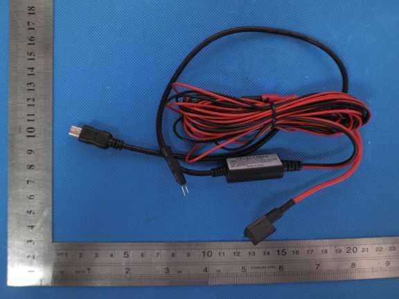
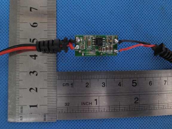
5 3. EUT DESCRIPTION Product Trade Mark Model Applicant Housing material EUT Type Serial Number Power Rating AC Line Car Charger MEKNIC SV-PC01 Supremevalue Technology CO., Ltd Plastic& Metal N/A Engineering Sample. Mass Product Sample. Input: DC 12-24V Output: DC 5V, 2A N/A Model list and Models difference Product Sample, No. Model Number Tested With 1 SV-PC01 Other Models SV-PC02,SV-PC03,SV-PC04,SV-PC05,SV-PC06,SV-PC07, SV-PC08,SV-PC09,SV-PC10,SV-PC11,SV-PC12,SV-PC13, SV-PC14,SV-PC15,SV-PC16,SV-PC17,SV-PC18,SV-PC19, SV-PC20 NOTE: SV-PC01 is tested model, other models are derivative models, The models are identicalin circuit, only different on the model names, size and capacity, So the test data of SV-PC01 canrepresent the remaining models. Page 5 of 46
6 4. TEST METHODOLOGY 4.1. DECISION OF FINAL TEST MODE The EUT was tested together with the thereinafter additional components, and a configuration, which produced the worst emission levels, was selected and recorded in this report. The following test mode(s) were scanned during the preliminary test: Pre-Test Mode Mode Conducted Emission Mode :Full load Emission Radiated Emission Mode :Full load After the preliminary scan, the following test mode was found to produce the highest emission level. The Worst Test Mode Conducted Emission Emission Radiated Emission Mode :Full load Mode :Full load 4.2. EUT SYSTEM OPERATION 1. Set up EUT with the support equipments. 2. Make sure the EUT work normally during the test. Page 6 of 46
7 5. SETUP OF EQUIPMENT UNDER TEST 5.1. DESCRIPTION OF SUPPORT UNITS The EUT has been tested as an independent unit together with other necessary accessories or support units. The following support units or accessories were used to form a representative test configuration during the tests. Note: 1) All the equipment/cables were placed in the worst-case configuration to maximize the emission during the test. 2) Grounding was established in accordance with the manufacturer s requirements and conditions for the intended use. Page 7 of 46
8 6. FACILITIES AND ACCREDITATIONS 6.1. FACILITIES All measurement facilities used to collect the measurement data are located at Shenzhen HTT Technology Co., Ltd. The sites are constructed in conformance with the requirements of ANSI C63.4 and CISPR Publication 32. All receiving equipment conforms to CISPR Publication 16-1, Radio Interference Measuring Apparatus and Measurement Methods ACCREDITATIONS Our laboratories are accredited and approved by the following approval agencies according to ISO/IEC USA Japan Canada Germany FCC VCCI INDUSTRY CANADA TUV Phoenix 6.3. MEASUREMENT UNCERTAINTY Where relevant, the following measurement uncertainty levels have been estimated for tests performed on the EUT as specified in CISPR : Measurement Frequency Uncertainty Conducted emissions 9kHz~30MHz +/- 3.59dB Horizontal Radiated emissions Vertical 30MHz ~ 200MHz +/- 4.77dB 200MHz ~1000MHz +/- 4.93dB 30MHz ~ 200MHz +/- 5.04dB 200MHz ~1000MHz +/- 4.93dB This uncertainty represents an expanded uncertainty expressed at approximately the 95% confidence level using a coverage factor of k=2. Page 8 of 46
9 7. EMISSION TEST 7.1. CONDUCTED EMISSION MEASUREMENT LIMITS NOTE: FREQUENCY (MHz) Quasi-peak Limit (dbuv) Average (1) The lower limit shall apply at the transition frequencies. (2) The limit decreases in line with the logarithm of the frequency in the range of 0.15 to 0.50 MHz. (3) All emanations from a class A/B digital device or system, including any network of conductors and apparatus connected thereto, shall not exceed the level of field strengths specified above TEST INSTRUMENTS Conducted Emission Shielding Room Test Site (843) Name of Equipment Manufacturer Model Serial Number Calibration Due EMI Test Receiver R&S ESCI /09/2018 LISN AFJ LS /09/2018 LISN(EUT) Mestec AN / /09/2018 NOTE: 1. The calibration interval of the above test instruments is 12 months and the calibrations are traceable to international system unit (SI). 2. N.C.R = No Calibration Request. Page 9 of 46
10 TEST PROCEDURES Procedure of Preliminary Test The EUT and Support equipment, if needed, was set up as per the test configuration to simulate typical usage per the user s manual. When the EUT is a tabletop system, a wooden table with a height of 0.8 meters is used and is placed on the ground plane as per EN55032 (see Test Facility for the dimensions of the ground plane used). When the EUT is a floor standing equipment, it is placed on the ground plane, which has a 3-12 mm non-conductive covering to insulate the EUT from the ground plane. All I/O cables were positioned to simulate typical actual usage as per EN All support equipment power received from a second LISN. The EUT test program was started. Emissions were measured on each current carrying line of the EUT using an EMI Test Receiver connected to the LISN powering the EUT. The Receiver scanned from 150kHz to 30MHz for emissions in each of the test modes. During the above scans, the emissions were maximized by cable manipulation. The test mode(s) described in Item 3.1 were scanned during the preliminary test. After the preliminary scan, we found the test mode described in Item 3.1 producing the highest emission level. The EUT configuration and cable configuration of the above highest emission levels were recorded for reference of the final test. Procedure of Final Test EUT and support equipment were set up on the test bench as per the configuration with highest emission level in the preliminary test. A scan was taken on both power lines, Line 1 and Line 2, recording at least the six highest emissions. Emission frequency and amplitude were recorded into a computer in which correction factors were used to calculate the emission level and compare reading to the applicable limit. The test data of the worst-case condition(s) was recorded. Page 10 of 46
11 TEST SETUP Vert. reference plane EMI receiver 40cm EUT 80cm LISN Reference ground plane For the actual test configuration, please refer to the related item Photographs of the Test Configuration TEST RESULTS 6dB Bandwidth 10 KHz Environmental Conditions 26 C, 55% RH Test Mode Full load Detector Function Peak / Quasi-peak/AV Test By Jack Chen Test Result N/A NOTE: 1. L1 = Line One (Live Line) / L2 = Line Two (Neutral Line) denotes the emission level was or more than 2dB below the Average limit, so no re-check anymore. Freq. = Emission frequency in MHz Reading level(dbuv) = Receiver reading Corr. Factor (db) = Antenna factor + Cable loss Level (dbuv) = Reading level(dbuv) + Corr. Factor (db) Limit (dbuv) = Limit stated in standard Margin (db) = Level (dbuv) Limits (dbuv) Q.P.=Quasi-Peak Page 11 of 46
12 7.2. RADIATED EMISSION MEASUREMENT LIMITS FREQUENCY (MHz) dbuv/m (At 3m) 30 ~ ~ NOTE: (1) The lower limit shall apply at the transition frequencies. (2) Emission level (dbuv/m) = 20 log Emission level (uv/m) TEST INSTRUMENTS Radiated Emission Test Site (966) Name of Equipment Manufacturer Model Serial Number Calibration Due EMI Test Receiver R&S ESCI /09/2018 Spectrum Analyzer R&S FSU /09/2018 Pre Amplifier H.P. HP8447E 2945A /09/2018 Bilog Antenna SUNOL Sciences JB3 A /09/2018 Cable TIME MICROWAVE LMR-400 N-TYPE04 06/09/2018 System-Controller CCS N/A N/A N.C.R Turn Table CCS N/A N/A N.C.R Antenna Tower CCS N/A N/A N.C.R NOTE: 1. The calibration interval of the above test instruments is 12 months and the calibrations are traceable to international system unit (SI). 2. N.C.R = No Calibration Request. Page 12 of 46
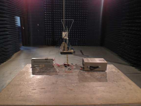
13 TEST PROCEDURE Procedure of Preliminary Test The equipment was set up as per the test configuration to simulate typical usage per the user s manual. When the EUT is a tabletop system, a wooden turntable with a height of 0.8 meters is used which is placed on the ground plane. When the EUT is a floor standing equipment, it is placed on the ground plane which has a 3-12 mm non-conductive covering to insulate the EUT from the ground plane. Support equipment, if needed, was placed as per EN All I/O cables were positioned to simulate typical usage as per EN from the outlet socket under the turntable. All support equipment power received from another socket under the turntable. Mains cables, telephone lines or other connections to auxiliary equipment located outside the test are shall drape to the floor, be fitted with ferrite clamps or ferrite tubes placed on the floor at the point where the cable reaches the floor and then routed to the place where they leave the turntable. No extension cords shall be used to mains receptacle. The antenna was placed at 10 meter away from the EUT as stated in EN The antenna connected to the Spectrum Analyzer via a cable and at times a pre-amplifier would be used. The Analyzer / Receiver quickly scanned from 30MHz to 1000MHz. The EUT test program was started. Emissions were scanned and measured rotating the EUT to 360 degrees and positioning the antenna 1 to 4 meters above the ground plane, in both the vertical and the horizontal polarization, to maximize the emission reading level. The test mode(s) described in Item 3.1 were scanned during the preliminary test: After the preliminary scan, we found the test mode described in Item 3.1 producing the highest emission level.the EUT and cable configuration, antenna position, polarization and turntable position of the above highest emission level were recorded for the final test. Procedure of Final Test EUT and support equipment were set up on the turntable as per the configuration with highest emission level in the preliminary test. The Analyzer / Receiver scanned from 30MHz to 1000MHz. Emissions were scanned and measured rotating the EUT to 360 degrees, varying cable placement and positioning the antenna 1 to 4 meters above the ground plane, in both the vertical and the horizontal polarization, to maximize the emission reading level. Recorded at least the six highest emissions. Emission frequency, amplitude, antenna position, polarization and turntable position were recorded into a computer in which correction factors were used to calculate the emission level and compare reading to the applicable limit and only Q.P. reading is presented. The test data of the worst-case condition(s) was recorded. Page 13 of 46
14 TEST SETUP Test table & Turntable 1m ~ 4m EUT Coaxial Cable Power Cable 0.8 m Filter Filter To Power 3 m EMI Receiver Ground Plane For the actual test configuration, please refer to the related item Photographs of the Test Configuration TEST RESULTS Pass Page 14 of 46
15 Page 15 of 46 This report shall not be reproduced except in full, without the written approval of Shenzhen HTT Technology Co., Ltd.
16 Page 16 of 46
17 7.3. HARMONICS CURRENT MEASUREMENT LIMITS OF HARMONICS CURRENT MEASUREMENT Limits for Class A equipment Harmonics Order n Max. permissible harmonics current A Odd harmonics Harmonics Order n Limits for Class D equipment Max. permissible harmonics current per watt ma/w Odd Harmonics only <=n<= x15/n 15<=n<= /n 0.15x15/n Even harmonics <=n<= x8/n NOTE: 1. Class A and Class D are classified according to item Max. permissible harmonics current A 2. According to section 7 of EN , the above limits apply for all equipments with a rated power more than 75W, except for lighting equipment TEST INSTRUMENTS Name of Equipment Manufacturer Model Serial Number Calibration Due Harmonic & Flicker Tester AC Power Source California instruments California instruments PACS-3 SB2588/01 06/09/ iX-CTS-40 SB /09/2018 NOTE: 1. The calibration interval of the above test instruments is 12 months and the calibrations are traceable to international system unit (SI). Page 17 of 46 This report shall not be reproduced except in full, without the written approval of Shenzhen HTT Technology Co., Ltd.
18 TEST PROCEDURE The EUT was placed on the top of a wooden table 0.8 meters above the ground and operated to produce the maximum harmonic components under Standard Mode operating conditions for each successive harmonic component in turn. The classification of EUT is according to section 5 of EN The EUT is classified as follows: Class A: Balanced three-phase equipment, Household appliances excluding equipment as Class D, Tools excluding portable tools, Dimmers for incandescent lamps, audio equipment, equipment not specified in one of the three other classes. Class B: Portable tools; Arc welding equipment which is not professional equipment. Class C: Lighting equipment. Class D: Equipment having a specified power less than or equal to 600 W of the following types: Personal computers and personal computer monitors and television receivers. The correspondent test program of test instrument to measure the current harmonics emanated from EUT is chosen. The measure time shall be not less than the time necessary for the EUT to be exercised. Page 18 of 46
19 TEST SETUP Harmonics & Flicker Analyzer + Power Source Power EUT Support Units 0.8m For the actual test configuration, please refer to the related item TEST RESULTS POWER CONSUMPTION ENVIRONMENTAL CONDITIONS rated power is less than Test Results N/A 75W 24.5deg.C, 56% RH, Limits Class A B C D 992 hpa Test Mode Full load Tested by Jack Chen NOTE: 1. Limits classified according to item There is no need for Harmonics test to be performed on this product(rated power is less than 75W) in accordance with EN :2014. For further details, please refer to Clause 7 of EN :2014 which states: For the following categories of equipment, limits are not specified in this edition of the standard: equipment with a rated power of 75W or less, other than lighting equipment. Page 19 of 46
20 7.4. VOLTAGE FLUCTUATION AND FLICKS MEASUREMENT LIMITS OF VOLTAGE FLUCTUATION AND FLICKS MEASUREMENT TEST ITEM LIMIT REMARK P st 1.0 P st means short-term flicker indicator. P lt 0.65 P lt means long-term flicker indicator. T dt (ms) 500 T dt means maximum time that dt exceeds 3 %. d max (%) 4% d max means maximum relative voltage change. dc (%) 3.3% dc means relative steady-state voltage change TEST INSTRUMENTS IMMUNITY SHIELDED ROOM Name of Equipment Manufacturer Model Serial Number Calibration Due Harmonic & Flicker Tester AC Power Source California instruments California instruments PACS-3 SB2588/01 06/09/ iX-CTS-40 SB /09/2018 NOTE: The calibration interval of the above test instruments is 12 months and the calibrations are traceable to international system unit (SI) TEST PROCEDURE The EUT was placed on the top of a wooden table 0.8 meters above the ground and operated to produce the most unfavorable sequence of voltage changes under Standard Mode operating conditions. During the flick measurement, the measure time shall include that part of whole operation cycle in which the EUT produce the most unfavorable sequence of voltage changes. The observation period for short-term flicker indicator is 10 minutes and the observation period for long-term flicker indicator is 2 hours. Page 20 of 46
21 TEST SETUP Harmonics & Flicker Analyzer + Power Source Power EUT Support Units 0.8m For the actual test configuration, please refer to the related item TEST RESULTS OBSERVATION PERIOD (Tp) ENVIRONMENTAL CONDITIONS Test Result 10mins Test Mode Full load 24.5deg.C, 56% RH, 992 hpa N/A Tested by: Jack Chen Page 21 of 46
22 8. IMMUNITY TEST 8.1. GENERAL DESCRIPTION Product Standard Basic Standard, Specification, and Performance Criterion required Test Type EN EN EN EN EN EN EN EN55024 Minimum Requirement Electrostatic Discharge ESD: 8kV air discharge, 4kV Contact discharge, Performance Criterion B Radio-Frequency Electromagnetic Field Susceptibility Test RS: 80 ~1000 MHz, 3V/m, 80% AM(1kHz), Performance Criterion A Electrical Fast Transient/Burst - EFT, Power line: 1kV, Signal line: 0.5kV, Performance Criterion B Surge Immunity Test: 1.2/50 us Open Circuit Voltage, 8 /20 us Short Circuit Current, Power Port ~ Line to line: 1kV, Line to ground: 2kV Signal Port ~ Lines to ground : 1kV Performance Criterion B Conducted Radio Frequency Disturbances Test CS: 0.15 ~ 80 MHz, 3Vrms, 80% AM, 1kHz, Performance Criterion A Power frequency magnetic field immunity test 50 Hz, 1A/m Performance Criterion A Voltage Dips: i) >95% reduction for 0.5 period, Performance Criterion B ii) 30% reduction for 25 period, Performance Criterion C Voltage Interruptions: >95% reduction for 250 period Performance Criterion C Page 22 of 46
23 8.2. GENERAL PERFORMANCE CRITERIA DESCRIPTION Criteria A: Criteria B: Criteria C: The apparatus shell continues to operate as intended without operator intervention. No degradation of performance or loss of function is allowed below a performance level specified by the manufacturer, when the apparatus is used as intended. The performance level may be replaced by a permissible loss of performance. If the manufacturer does not specify the minimum performance level or the permissible performance loss, then either of these may be derived from the product description and documentation, and by what the user may reasonably expect from the equipment if used as intended. After test, the apparatus shell continues to operate as intended without operator intervention. No degradation of performance or loss of function is allowed, after the application of the phenomenon below a performance level specified by the manufacturer, when the apparatus is used as intended. The performance level may be replaced by a permissible loss of performance. During the test, degradation of performance is however allowed. However, no change of operating state if stored data is allowed to persist after the test. If the manufacturer does not specify the minimum performance level or the permissible performance loss, then either of these may be derived from the product description and documentation, and by what the user may reasonably expect from the equipment if used as intended. Temporary loss of function is allowed, provided the functions is self-recoverable or can be restored by the operation of controls by the user in accordance with the manufacturer instructions. Functions, and/or information stored in non-volatile memory, or protected by a battery backup, shall not be lost. Page 23 of 46
24 8.3. ELECTROSTATIC DISCHARGE (ESD) TEST SPECIFICATION Basic Standard: EN Discharge Impedance: 330ohm Charging capacity: 150pF Discharge Voltage: Air Discharge: 8 kv (Direct) Contact Discharge: 4 kv (Direct/Indirect) Polarity: Positive & Negative Number of Discharge: Minimum 10 times at each test point Discharge Mode: Single Discharge 1 second minimum Performance criterion: B TEST INSTRUMENT IMMUNITY SHIELDED ROOM Name of Equipment Manufacturer Model Serial Number Calibration Due ESD 2000 EMC PARTNER ESD /09/2018 NOTE: The calibration interval of the above test instruments is 12 months and the calibrations are traceable to international system unit (SI). Page 24 of 46
25 TEST PROCEDURE The discharges shall be applied in two ways: a) Contact discharges to the conductive surfaces and coupling planes: Twenty dischargers (10 with positive and 10 with negative polarity) shall be applied on each accessible metallic part of the enclosure, terminals are excluded. In case of a non-conductive enclosure, dischargers shall be applied on the horizontal or vertical coupling planes. Test shall be performed at a maximum repetition rate of one discharge per second. b) Air discharges at slots and apertures and insulating surfaces: On those parts of the EUT where it is not possible to perform contact discharge testing, the equipment should be investigated to identify user accessible points where breakdown may occur. Such points are tested using the air discharge method. This investigation should be restricted to those area normally handled by the user. A minimum of 10 single air discharges shall be applied to the selected test point for each such area. The basic test procedure was in accordance with IEC : a) The EUT was located 0.1 m minimum from all side of the HCP (dimensions 1.6m x 0.8m). b) The support units were located another table 30 cm away from the EUT, but direct support unit was/were located at same location as EUT on the HCP and keep at a distance of 10 cm with EUT. c) The time interval between two successive single discharges was at least 1 second. d) Contact discharges were applied to the non- insulating coating, with the pointed tip of the generator penetrating the coating and contacting the conducting substrate. e) Air discharges were applied with the round discharge tip of the discharge electrode approaching the EUT as fast as possible (without causing mechanical damage) to touch the EUT. After each discharge, the ESD generator was removed from the EUT and re-triggered for a new single discharge. The test was repeated until all discharges were complete. f) At least ten single discharges (in the most sensitive polarity) were applied at the front edge of each HCP opposite the center point of each unit of the EUT and 0.1 meters from the front of the EUT. The long axis of the discharge electrode was in the plane of the HCP and perpendicular to its front edge during the discharge. g) At least ten single discharges (in the most sensitive polarity) were applied to the center of one vertical edge of the Vertical Coupling Plane (VCP) in sufficiently different positions that the four faces of the EUT were completely illuminated. The VCP (dimensions 0.5m x 0.5m) was placed vertically to and 0.1 meters from the EUT. Page 25 of 46
26 TEST SETUP 10 cm VCP Support units 0.5 mm Thick InCheneytor EUT 470 kω 30 cm 470 kω Wooden Table HCP Wooden Table 470 kω 0.8 m Ground Reference Plane For the actual test configuration, please refer to the related item Photographs of the Test Configuration. NOTE: TABLE-TOP EQUIPMENT The configuration consisted of a wooden table 0.8 meters high standing on the Ground Reference Plane. The GRP consisted of a sheet of aluminum at least 0.25mm thick, and 2.5 meters square connected to the protective grounding system. A Horizontal Coupling Plane (1.6m x 0.8m) was placed on the table and attached to the GRP by means of a cable with 940k total impedance. The equipment under test, was installed in a representative system as described in section 7 of EN , and its cables were placed on the HCP and isolated by an insulating support of 0.5mm thickness. A distance of 1-meter minimum was provided between the EUT and the walls of the laboratory and any other metallic structure. FLOOR-STANDING EQUIPMENT The equipment under test was installed in a representative system as described in section 7 of IEC , and its cables were isolated from the Ground Reference Plane by an insulating support of 0.1-meter thickness. The GRP consisted of a sheet of aluminum that is at least 0.25mm thick, and 2.5 meters square connected to the protective grounding system and extended at least 0.5 meters from the EUT on all sides. Page 26 of 46
27 TEST RESULTS Temperature: 25 o C Humidity 55% RH Pressure 996mbar Test result Pass Test mode Full load Test By Jack Chen Test locations Air Discharge Test Levels Results Performance ± 2 kv ± 4 kv ± 8 kv Pass Fail Criterion Observation Slots 8Points B Note 1 2 Test locations Contact Discharge Test Levels Results Performance ± 2 kv ± 4 kv ± 8 kv Pass Fail Criterion Observation HCP 4Points B Note 1 2 VCP 4Points B Note 1 2 USB port 4Points B Note 1 2 NOTE: 1. There was no change compared with initial operation during the test. 2. The loss of function of the EUT during the test and it was recovered by itself operation after the test. 3. N/A mean to no applicable. Page 27 of 46
28 8.4. RADIATED, RADIO-FREQUENCY, ELECTROMAGNETIC FIELD (RS) TEST SPECIFICATION Basic Standard: EN Frequency Range: 80 MHz ~1000 MHz, Field Strength: 3 V/m Modulation: 1kHz Sine Wave, 80%, AM Modulation Frequency Step: 1 % of preceding frequency value Polarity of Antenna: Horizontal and Vertical Test Distance: 3 m Antenna Height: 1.5m Performance Criterion: A TEST INSTRUMENT 743 RS Chamber Name of Equipment Manufacturer Model Serial Number Calibration Due Signal Generator Maconi 2022D /003 06/09/2018 Power Amplifier M2S A /09/2018 Power Amplifier M2S AC8113/ A /09/2018 Power Antenna SCHAFFNER CBL6140A /09/2018 NOTE: 1. The calibration interval of the above test instruments is 12 months and the calibrations are traceable to international system unit (SI). 2. N.C.R.= No Calibration required TEST PROCEDURE The test procedure was in accordance with EN a) The testing was performed in a fully anechoic chamber. The transmit antenna was located at a distance of 3 meters from the EUT. b) The frequency range is swept from 80 MHz to 1000 MHz, with the signal 80% amplitude modulated with a 1kHz sine-wave. The rate of sweep did not exceed 1.5 x 10⁻³ decade/s, where the frequency range is swept incrementally, the step size was 1% of preceding frequency value. c) The dwell time at each frequency shall be not less than the time necessary for the EUT to be able to respond. d) The test was performed with the EUT exposed to both vertically and horizontally polarized fields on each of the four sides. Page 28 of 46
29 TEST SETUP 9X6X6 3m EUT& Support 0.8m Power Amp Signal Generator EUT Monitoring by using a camera PC Controller to control S.G. & PA as well as forward power Control Room For the actual test configuration, please refer to the related item. NOTE: TABLETOP EQUIPMENT The EUT installed in a representative system as described in section 7 of EN was placed on a non-conductive table 0.8 meters in height. The system under test was connected to the power and signal wire according to relevant installation instructions. FLOOR STANDING EQUIPMENT The EUT installed in a representative system as described in section 7 of IEC was placed on a non-conductive wood support 0.1 meters in height. The system under test was connected to the power and signal wire according to relevant installation instructions. Page 29 of 46
30 TEST RESULTS Temperature: 25 o C Humidity 50% RH Pressure 996mbar Test result Pass Test mode Full load Test By Jack Chen Frequency (MHz) Polarity Postion Field Strength (V/m) Observation Result 80 ~ 1000 V&H Front 3 Note Pass 80 ~ 1000 V&H Rear 3 Note Pass 80 ~ 1000 V&H Left 3 Note Pass 80 ~ 1000 V&H Right 3 Note Pass NOTE: 1.There was no change compared with the initial operation during the test. Page 30 of 46
31 8.5. ELECTRICAL FAST TRANSIENT (EFT) TEST SPECIFICATION Basic Standard: EN Test Voltage: Power Line: 1 kv Signal/Control Line: 0.5 kv Polarity: Positive & Negative Impulse Frequency: 5 khz Impulse Wave-shape: 5/50 ns Burst Duration: 15 ms Burst Period: 300 ms Test Duration: Not less than 1 min. Performance criterion: B TEST INSTRUMENT Immunity Shield Room Name of Equipment Manufacturer Model Serial Number Calibration Due EMC PARTNER TRANSIENT 2000 EMC PARTNER TRA /09/2018 NOTE: 1. The calibration interval of the above test instruments is 12 months and the calibrations are traceable to international system unit (SI). 2. N.C.R.= No Calibration required TEST PROCEDURE a) Both positive and negative polarity discharges were applied. b) The length of the hot wire from the coaxial output of the EFT generator to the terminals on the EUT should not exceed 1 meter. c) The duration time of each test sequential was 1 minute. d) The transient/burst waveform was in accordance with EN , 5/50ns. Page 31 of 46
32 TEST SETUP EUT Support Units AC EFT/Burst/ Surge Generator 0.8m Non-Conductive Table Controller Computer To Load Comm. Line 3 m 10cm EUT AC Burst Generator Injection Clamp Non-Conductive Table 0.8m For the actual test configuration, please refer to the related item Photographs of the Test Configuration. NOTE: TABLETOP EQUIPMENT The configuration consisted of a wooden table (0.8m high) standing on the Ground Reference Plane. The GRP consisted of a sheet of aluminum (at least 0.25mm thick and 2.5m square) connected to the protective grounding system. A minimum distance of 0.5m was provided between the EUT and the walls of the laboratory or any other metallic structure. FLOOR STANDING EQUIPMENT The EUT installed in a representative system as described in section 7 of IEC and its cables, were isolated from the Ground Reference Plane by an insulating support that is 0.1-meter thick. The GRP consisted of a sheet of aluminum (at least 0.25mm thick and 2.5m square) connected to the protective grounding system. Page 32 of 46
33 TEST RESULTS Temperature: 25 o C Humidity 50% RH Pressure 996mbar Test result N/A Test mode Full load Test By Jack Chen Test Point Polarity Test Level (kv) Performance Criterion Observation Result L +/- 1 B Note 1 2 N/A N +/- 1 B Note 1 2 N/A L N +/- 1 B Note 1 2 N/A PE +/- 1 B Note 1 2 N/A L PE +/- 1 B Note 1 2 N/A N PE +/- 1 B Note 1 2 N/A L N PE +/- 1 B Note 1 2 N/A Signal Line Note 1 2 N/A NOTE: 1. There was no change compared with initial operation during the test. 2. The loss of function of the EUT during the test and it was recovered by itself operation after the test. Page 33 of 46
34 8.6. SURGE IMMUNITY TEST TEST SPECIFICATION Basic Standard: EN Wave-Shape: Combination Wave 1.2/50 us Open Circuit Voltage 8/20 us Short Circuit Current Test Voltage: Power line ~ line to line: 1 kv; line to ground: 2kV Telecommunication line: 1 kv; Surge Input/Output: Power Line: L-N / L-PE / N-PE Telecommunication line: T-Ground / R-Ground Generator Source Impedance: 2 ohm between networks 12 ohm between network and ground Polarity: Positive/Negative Phase Angle: 0 /90 /180 /270 Pulse Repetition Rate: 1 time / min. (maximum) Number of Tests: 5 positive and 5 negative at selected points Performance Criterion: B TEST INSTRUMENT Immunity Shield Room Name of Equipment Manufacturer Model Serial Number Calibration Due EMC PARTNER TRANSIENT 2000 EMC PARTNER TRA /09/2018 NOTE: 1. The calibration interval of the above test instruments is 12 months and the calibrations are traceable to international system unit (SI). 2. N.C.R.= No Calibration required Page 34 of 46
35 TEST PROCEDURE a) For EUT power supply: The surge is applied to the EUT power supply terminals via the capacitive coupling network. Decoupling networks are required in order to avoid possible adverse effects on equipment not under test that may be powered by the same lines, and to provide sufficient decoupling impedance to the surge wave. The power cord between the EUT and the coupling/decoupling networks was shorter than 2 meters in length. b) For test applied to unshielded un-symmetrically operated interconnection lines of EUT: The surge was applied to the lines via the capacitive coupling. The coupling / decoupling networks didn t influence the specified functional conditions of the EUT. The interconnection line between the EUT and the coupling/decoupling networks was shorter than 2 meters in length. c) For test applied to unshielded symmetrically operated interconnection / telecommunication lines of EUT: The surge was applied to the lines via gas arrestors coupling. Test levels below the ignition point of the coupling arrestor were not specified. The interconnection line between the EUT and the coupling/decoupling networks was shorter than 2 meters in length TEST SETUP To AC Source Surge Immunity Test EUT & Support Units 0.8m Controller Computer For the actual test configuration, please refer to the related item Photographs of the Test Configuration. Page 35 of 46
36 TEST RESULTS Temperature: 25 o C Humidity 50% RH Pressure 996mbar Test result N/A Test mode Full load Test By Jack Chen Test Point Polarity Test Level (kv) Performance Criterion Observation Result L-N +/- 1 B Note 1 2 N/A L- PE +/- 2 B Note 1 2 N/A N - PE +/- 2 B Note 1 2 N/A R - Ground Note 1 2 N/A T - Ground Note 1 2 N/A NOTE: 1. There was no change compared with initial operation during the test. 2. The loss of function of the EUT during the test and it was recovered by itself operation after the test. Page 36 of 46
37 8.7. CONDUCTED RADIO FREQUENCY DISTURBANCES (CS) TEST SPECIFICATION Basic Standard: EN Frequency Range: 0.15 MHz ~ 80 MHz Field Strength: 3 V Modulation: 1kHz Sine Wave, 80%, AM Modulation Frequency Step: 1 % of preceding frequency value Coupled cable: Power Mains, Shielded Coupling device: CDN-M3/2 (2 wires) Performance criterion: A TEST INSTRUMENT CS Test Name of Equipment Manufacturer Model Serial Number Calibration Due Signal Generator Maconi 2022D /003 06/09/2018 Power Amplifier M2S A /09/2018 CDN MEB M /09/2018 NOTE: 1. The calibration interval of the above test instruments is 12 months and the calibrations are traceable to international system unit (SI). 2. N.C.R.= No Calibration required Page 37 of 46
38 TEST PROCEDURE The EUT shall be tested within its intended operating and climatic conditions. The test shell performed with the test generator connected to each of the coupling and decoupling devices in turn, while the other non-excited RF input ports of the coupling devices are terminated by a 50-ohm load resistor. The frequency range was swept from 150 khz to 80 MHz, using the signal level established during the setting process and with a disturbance signal of 80 % amplitude. The signal was modulated with a 1 khz sine wave, pausing to adjust the RF signal level or the switch coupling devices as necessary. The sweep rate was 1.5 x 10⁻³ decades/s. Where the frequency range is swept incrementally, the step size was 1 % of preceding frequency value from 150 khz to 80 MHz. The dwell time at each frequency was less than the time necessary for the EUT to be exercised, and able to respond. Sensitive frequencies such as clock frequency(ies) and harmonics or frequencies of dominant interest, was analyzed separately. Attempts was made to fully exercise the EUT during testing, and to fully interrogate all exercise modes selected for susceptibility TEST SETUP Power PC 10 cm isolation supporter 0.1m< L <0.3m Amplifier Controller EUT and Support units CDN Note: 1. The EUT is setup 0.1m above Ground Reference Plane 2. The CDNS and / or EM clamp used for real test depends on ports and cables configuration of EUT. For the actual test configuration, please refer to the related item. NOTE: TABLE-TOP AND FLOOR-STANDING EQUIPMENT The equipment to be tested is placed on an insulating support of 0.1 meters height above a ground reference plane. All relevant cables shall be provided with the appropriate coupling and decoupling devices at a distance between 0.1 meters and 0.3 meters from the projected geometry of the EUT on the ground reference plane. Page 38 of 46
39 TEST RESULTS Temperature: 25 o C Humidity 50% RH Pressure 996mbar Test result N/A Test mode Full load Test By Jack Chen Frequency Band (MHz) Field Strength (Vrms) Injected Position Injection Method Performance Criterion Observation Result 0.15 ~ 80 3 AC Mains CDN-M2 A Note 1 2 N/A NOTE: 1. There was no change compared with initial operation during the test. 2. The loss of function of the EUT during the test and it was recovered by itself operation after the test. 3. N/A means to no applicable. Page 39 of 46
40 8.8. POWER FREQUENCY MAGNETIC FIELD TEST SPECIFICATION Basic Standard: EN Frequency Range: 50Hz Field Strength: 1A/m Observation Time: 5 minutes Inductance Coil: Rectangular type, 1mx1m Performance criterion: A TEST INSTRUMENT Immunity Shield Room Name of Equipment Manufacturer Model Serial Number Calibration Due Power-frequency Magnetic field SCHAFFNER CCN /09/2018 Induction Coil Interface SCHAFFNER INA /09/2018 NOTE: 1. The calibration interval of the above test instruments is 12 months and the calibrations are traceable to international system unit (SI). 2. N.C.R.= No Calibration required TEST PROCEDURE a. The equipment is configured and connected to satisfy its functional requirements. It shall be placed on the GRP with the interposition of a 0.1m-thick insulating support. b. The equipment cabinets shall be connected to the safety earth directly on the GRP via the earth terminal of the EUT. c. The power supply, input and output circuits shall be connected to the sources of power supply, control and signal. d. The cables supplied or recommended by the equipment manufacturer shall be used. 1 meter of all cables used shall be exposed to the magnetic field. Page 40 of 46
41 TEST SETUP Induction Coil 1/2 Dimension of EUT EUT Signal Generator To Earth Ground For the actual test configuration, please refer to the related item. NOTE: TABLETOP EQUIPMENT The equipment shall be subjected to the test magnetic field by using the induction coil of standard dimension (1 m x 1 m). The induction coil shall then be rotated by 90 degrees in order to expose the EUT to the test field with different orientations. FLOOR-STANDING EQUIPMENT The equipment shall be subjected to the test magnetic field by using induction coils of suitable dimensions. The test shall be repeated by moving and shifting the induction coils, in order to test the whole volume of the EUT for each orthogonal direction. The test shall be repeated with the coil shifted to different positions along the side of the EUT, in steps corresponding to 50 % of the shortest side of the coil. The induction coil shall then be rotated by 90 degrees in order to expose the EUT to the test field with different orientations TEST RESULTS Temperature: 25 o C Humidity 50% RH Pressure 996mbar Test result N/A Test mode Full load Test By Jack Chen DIRECTION Field Strength (A/m) Performance Criterion OBSERVATION RESULTS X 1 A Note 1 2 N/A Y 1 A Note 1 2 N/A Z 1 A Note 1 2 N/A NOTE: 1. There was no change compared with initial operation during the test. 2. The loss of function of the EUT during the test and it was recovered by itself operation after the test. Page 41 of 46
42 8.9. VOLTAGE DIP & VOLTAGE INTERRUPTIONS TEST SPECIFICATION Basic Standard: EN Test duration time: Minimum three test events in sequence Interval between event: Minimum 10 seconds Phase Angle: 0 /45 / 90/ 135/ 180/ 225/ 270/ 315/ 360 Test cycle: 3 times Performance criterion: B,C TEST INSTRUMENT Immunity shielded room Name of Equipment Manufacturer Model Serial Number Calibration Due EMC PARTNER TRANSIENT 2000 EMC PARTNER TRA /09/2018 NOTE: 1. The calibration interval of the above test instruments is 12 months and the calibrations are traceable to international system unit (SI). 2. N.C.R.= No Calibration required TEST PROCEDURE 1. The EUT and support units were located on a wooden table, 0.8 m away from ground floor. 2. Setting the parameter of tests and then perform the test software of test simulator. 3. Conditions changes to occur at 0 degree crossover point of the voltage waveform. 4. Recording the test result in test record form. Page 42 of 46
43 TEST SETUP To AC Source Dips/Interruption and Variations Simulator EUT & Support Units 0.8m Controller Computer For the actual test configuration, please refer to the related item Photographs of the Test Configuration TEST RESULTS Temperature: 25 o C Humidity 50% RH Pressure 996mbar Test result N/A Test mode Full load Test By Jack Chen Voltage (% Reduction) Duration (Period) Performance Criterion Observation Test Result A B C Note N/A A B C Note N/A A B C Note N/A NOTE: 1.There was no change compared with initial operation during and after the test. No unintentional response was found during the test. 2.The function stopped during the test, but can be recoverable by itself operation after the test. 3.The function stopped during the test, but can be recoverable manually after the test. Page 43 of 46
44 9 PHOTOGRAPHS OF EUT Page 44 of 46

45 Page 45 of 46

46 Page 46 of 46
CE EMC Test Report GUANGZHOU DMKEMOTOR CO. LTD
 CE REPORT CE EMC Test Report Equipment under Test: Model /Type: Applicant: Address: Manufacturer: Address: Laboratory: Address: Report Number Brush D.C. Motor D5D120-24GU D2D10-12GN, D2D10-24GN, D2D10-36GN,
EMC TEST REPORT For MPP SOLAR INC Inverter/ Charger Model Number : PIP 4048HS
 EMC-E20130903E EMC TEST REPORT For MPP SOLAR INC Inverter/ Charger Model Number : PIP 4048HS Prepared for : MPP SOLAR INC Address : 4F, NO. 50-1, SECTION 1, HSIN-SHENG S. RD. TAIPEI, TAIWAN Prepared by
No. 620 HuaYuan Commercial Center, No. 347 XiXiang Road,XiXiang Town, Bao An District, ShenZhen City Tel : Fax:
 No. 620 HuaYuan Commercial Center, No. 347 XiXiang Road,XiXiang Town, Bao An District, ShenZhen City Tel : +86-755-27912080 Fax: +86-755-27916936 FCC TEST REPORT Product name : 7PORT DUAL SUPPLY POE SWITCH
CE EMC TEST REPORT. For EMERGENCY BATTERY KIT V-TAC EXPORTS LIMITED V-TAC EXPORTS LIMITED. Global-Standard Testing Service Co., Ltd.
 CE EMC TEST REPORT For EMERGENCY BATTERY KIT Model No.: VT-510, VT-514, VT-515, VT-518, VT-530, VT-511, VT-503 Applicant : V-TAC EXPORTS LIMITED ROOM NO.301, KAM ON BUILDING 176A QUEENS ROAD CENTRAL, CENTRAL,
EMC TEST REPORT. Report No.: CE10-LIE040101E
 EMC TEST REPORT Report No.: CE10-LIE040101E Product: LED TUBE Model No.: T10, T8, T5 Applicant: Shenzhen Saiju Electronic Co., Ltd. Address: 2nd. Xianshun Industrial Park, Gushu, Xixiang, Bao an, Shenzhen,
EMC TEST REPORT. for. Coliy Technology Co.,Ltd. Fluxgate Gaussmeter
 Page 1 of 48 EMC TEST REPORT for Coliy Technology Co.,Ltd. Fluxgate Gaussmeter Prepared for : Coliy Technology Co.,Ltd. Address : Block B,9 th Floor,Xinzhongtai Business Building,Gushu 2nd Road,Xi Town,Bao
TEST REPORT... 1 CONTENT...
 CONTENT TEST REPORT... 1 CONTENT... 2 1 TEST RESULTS SUMMARY... 3 2 EMC RESULTS CONCLUSION... 4 3 LABORATORY MEASUREMENTS... 6 4 EMI TEST... 7 4.1 CONTINUOUS CONDUCTED DISTURBANCE VOLTAGE TEST... 7 4.2
TEST SUMMARY. Prüfbericht - Nr.: Test Report No.: Seite 2 von 25. Page 2 of 25
 15072259 001 Seite 2 von 25 Page 2 of 25 TEST SUMMARY 4.1.1 HARMONICS ON AC MAINS 4.1.2 VOLTAGE FLUCTUATIONS ON AC MAINS 4.1.3 MAINS TERMINAL CONTINUOUS DISTURBANCE VOLTAGE 4.1.4 DISCONTINUOUS INTERFERENCE
TEST SUMMARY. Prüfbericht - Nr.: Test Report No.: Seite 2 von 27. Page 2 of 27
 15072768 001 Seite 2 von 27 Page 2 of 27 TEST SUMMARY 4.1.1 HARMONICS ON AC MAINS 4.1.2 VOLTAGE CHANGES, VOLTAGE FLUCTUATIONS AND FLICKER ON AC MAINS 4.1.3 MAINS TERMINAL CONTINUOUS DISTURBANCE VOLTAGE
TEST REPORT. Product: Thermo-Hygrometer Model No.: FL-201, FL-201W Trade mark: N/A Report No.: TCT151014E001 Issued Date: Oct. 15, 2015.
 TEST REPORT Product: Thermo-Hygrometer Model No.: FL-201, FL-201W Trade mark: N/A Report No.: TCT151014E001 Issued Date: Oct. 15, 2015 Issued for: Shenzhen Flus Technology Co., Ltd 3rd Floor, Lantian Building,
Harmonic Current emission EN :2014 Class A Pass. Voltage Fluctuation and Flicker EN :2013 Clause 5 Pass
 Reference No.: WTS15F0323845E Page 2 of 33 1 Test Summary Test Item Mains Terminal Disturbance Voltage, 148.5kHz to 30MHz Disturbance Power, 30MHz to 300MHz Discontinuous Disturbance (Click) Radiated Emission,
EN 55015: 2013 Clause Pass. EN 55015: 2013 Clause Pass. EN 55015: 2013 Clause Pass
 Reference No.: WTD15S0730643E Page 2 of 42 1 Test Summary Test Item Conducted Disturbance at Mains Terminal, 9kHz to 30MHz Radiation electromagnetic disturbance, 9kHz to 30MHz Radiation Emission, 30MHz
Discontinuous Disturbance (Click) EN :2006+A1:2009+A2:2011 Clause N/A** Radiated Emission, 30MHz to 1000MHz
 EN :2006+A1:2009+A2:2011 Clause N/A** Radiated Emission, 30MHz to 1000MHz") Reference No.: WTN13F0706038E Page 2 of 40 1 Test Summary Test Item Mains Terminal Disturbance Voltage, 148.5kHz to 30MHz Disturbance Power, 30MHz to 300MHz EMISSION Test Standard Class / Severity Result
Reference No.: WTN13F0706038E Page 2 of 40 1 Test Summary Test Item Mains Terminal Disturbance Voltage, 148.5kHz to 30MHz Disturbance Power, 30MHz to 300MHz EMISSION Test Standard Class / Severity Result
Test Report. Guangdong East Power Co., Ltd. Fully Automatic AC Voltage Regulator. Brand Name:
 Test Report Applicant: Product Name: Brand Name: Model No.: Guangdong East Power Co., Ltd. Fully Automatic AC Voltage Regulator EAST ZTY-30KVA Date of Receipt : Aug. 30, 2013 Date of Test: Sep. 03, 2013
Prepared for Address. : KST DIGITAL TECHNOLOGY LIMITED : No.226, Pangu Street, Meixian, Meizhou, Guangdong. Prepared by
 EMC TEST REPORT For KST DIGITAL TECHNOLOGY LIMITED Coreless Servo Model No.: X12-508 Additional Model No.: DS215MG, DS315MG, DS213MG, DS313MG, DS12C, DS12T, X12-306 Prepared for Address : KST DIGITAL TECHNOLOGY
CE-EMC TEST REPORT. Prepared for : T&T Assoociates London LTD Suite#306 CityGate House, Bussinedd Centre Stratford, Romford Road, London
 CE-EMC TEST REPORT Prepared for : T&T Assoociates London LTD Suite#306 CityGate House, Bussinedd Centre Stratford, 246-250 Romford Road, London Product: CCTV Camera Trade Name: Model Name: INNOVEXS IPBQH20HH205,
FCC Verification TEST REPORT
 FCC Verification TEST REPORT Product: 5 in 1 Environment Meter Model no.: ET-965 Trade Mark: N/A Report No.: TCT140915E005 Issued Date: Sep. 22, 2014 Issued for: Shenzhen Flus Technology Co., Ltd 3rd Floor,
EN 55022: 2010+AC:2011 Clause 6.1 Pass. Harmonic Current EN :2006+A1:2009+A2:2009 Class A N/A
 Reference No.: WT12106773-N-S-E Page 2 of 33 1 Test Summary Test Item Mains Terminal Disturbance Voltage, 150KHz to 30MHz Radiation Emission, 30MHz to 1000MHz EMISSION Test Standard Class / Severity Result
Overview of EMC Regulations and Testing. Prof. Tzong-Lin Wu Department of Electrical Engineering National Taiwan University
 Overview of EMC Regulations and Testing Prof. Tzong-Lin Wu Department of Electrical Engineering National Taiwan University What is EMC Electro-Magnetic Compatibility ( 電磁相容 ) EMC EMI (Interference) Conducted
Test Report GUANGDONG EAST POWER CO., LTD
 Test Report Applicant: Product Name: Brand Name: Model No.: GUANGDONG EAST POWER CO., LTD Online High Frequency UPS EAST EA906IIRTS, EA906IIRTH Date of Receipt : Feb. 26, 2014 Date of Test: Mar. 24, 2014
EMC TEST REPORT for SHENZHEN MUST ENERGY TECHNOLOGY CO., LTD
 Page 1 of 45 Report No. R011607240E EMC TEST REPORT for SHENZHEN MUST ENERGY TECHNOLOGY CO., LTD INVERTER CHARGER Model No.: PV35-4K DC24V MPK, PV35-4K DC48V MPK, PV35-5K DC48V MPK, PV35-6K DC48V MPK Prepared
CE-EMC TEST REPORT. Test report On Behalf of MAZi Security Systems GmbH For TVI CCTV Camera Model No.: TDE-11S; Serial Model See Page 2
 Page 1 of 55 CE-EMC TEST REPORT Test report On Behalf of MAZi Security Systems GmbH For TVI CCTV Camera Model No.: TDE-11S; Serial Model See Page 2 Prepared for : MAZi Security Systems GmbH Ostwall 216,
EMC TEST REPORT. For. Switching Mode Power Adaptor. Model No.: 9W/14.4V/EU(18V/1.0A), 19W/14.4V/EU(12V/1.5A)
, 19W/14.4V/EU(12V/1.5A)") EMC TEST REPORT For Company Limited Liability «Faraday Electronics» Switching Mode Power Adaptor Model No.: 9W/14.4V/EU(18V/1.0A), 19W/14.4V/EU(12V/1.5A) Prepared For : Company Limited Liability «Faraday
EMC TEST REPORT For Company Limited Liability «Faraday Electronics» Switching Mode Power Adaptor Model No.: 9W/14.4V/EU(18V/1.0A), 19W/14.4V/EU(12V/1.5A) Prepared For : Company Limited Liability «Faraday
FCC 47 CFR PART 15 SUBPART B
 FCC 47 CFR PART 15 SUBPART B TEST REPORT For DC TO DC CONVERTER Model : D100 Series Issued for MicroPower Direct, LLC 232 Tosca Drive Stoughton, MA02072 U.S.A. Issued by Compliance Certification Services
ITUNER NETWORKS CORPORATION EMC REPORT Fremont Blvd. Fremont, CA
 Shenzhen BST Technology Co., Ltd. ITUNER NETWORKS CORPORATION EMC REPORT Prepared For : ITUNER NETWORKS CORPORATION 47801 Fremont Blvd. Fremont, CA. 94538 Product Name: PicoPSU-150 Trade Name: PicoPSU
EMC REPORT. ShenZhen KY Technology Co.,Ltd. No.369, BaoTian 1st RD, TieGang Industrial Park, Xixiang Town, Baoan District, ShenZhen, PRC.
 Report No.: UNI2016121702ER-01 Page 1 / 30 ShenZhen KY Technology Co.,Ltd EMC REPORT Prepared For: ShenZhen KY Technology Co.,Ltd Product Name: Smart bracelet No.369, BaoTian 1st RD, TieGang Industrial
CE EMC TEST REPORT. For LED EMERGENCY LIGHTS AND SIGNAL BOARDS SEGURIMAX TRADING SA. Global-Standard Testing Service Co., Ltd.
 CE EMC TEST REPORT For LED EMERGENCY LIGHTS AND SIGNAL BOARDS Model No.: LED 288 LUMENS WITH SENSOR, SINALIZACAO SAIDA SLIM 50X25 verde, SINALIZACAO SAIDA PREMIUM 60X30, SINALIZACAO BANHEIROS Applicant
EMC Test Report For Changzhou Airwheel Technology Co.,Ltd. Airwheel Model: A6S,A6,A6P,A6PS,A6T,A6TS
 EMC Test Report For Changzhou Airwheel Technology Co.,Ltd. Airwheel Model: A6S,A6,A6P,A6PS,A6T,A6TS Prepared For : Prepared By : Changzhou Airwheel Technology Co.,Ltd. Fl.5, East of No. 10 Building, high-tech
CE EMC TEST REPORT. Model Name: JZH-RF898B JZH-RX898B Report No.: BCTC E. Prepared for
 Shenzhen BCTC Technology Co., Ltd. Report No.: BCTC-160608172-2E CE EMC TEST REPORT Product: Fishing bite alarm Trade Name: Model Name: JZH-RF898B JZH-RX898B Report No.: BCTC-160608172-2E Prepared for
TEST REPORT. Issued for:
 TEST REPORT Product: Polymer lithium battery Model No.: LP477592 (Other models see model list of page 5) Trade mark: EWT Report No.: TCT170306E010 Issued Date: Mar. 08, 2017 Issued for: EVERWIN TECH CO.,
EMC standards. Presented by: Karim Loukil & Kaïs Siala
 Training Course on Conformity and Interoperability on Type Approval testing for Mobile Terminals, Homologation Procedures and Market Surveillance, Tunis-Tunisia, from 20 to 24 April 2015 EMC standards
EMC TEST REPORT For ShenZhen ZhangQing Electronic LTD poe tester Model No.: WS POE Tester/Detector Additional Model No: Please Refer to Page 8
 EMC TEST REPORT For ShenZhen ZhangQing Electronic LTD poe tester Model No.: WS POE Tester/Detector Additional Model No: Please Refer to Page 8 Prepared for Address : ShenZhen ZhangQing Electronic LTD :
APPLICATION FOR EMC DIRECTIVE. On Behalf of. Shenzhen Qinhan Lighting Co., Ltd. led flood light. Trade Name:
 APPLICATION FOR EMC DIRECTIVE On Behalf of Shenzhen Qinhan Lighting Co., Ltd led flood light Trade Name: Model: QH-TGC-400W, QH-TGC-300W, QH-TGC-500W, QH-TGC-800W, QH-TGC-1000W Prepared For : Shenzhen
CE-EMC TEST REPORT. Prepared for : Kinglumi Co., Ltd. Bldg 3, Nangang 3nd Industrial Zone, Tangtou, Shiyan Town, Bao an District, Shenzhen City, China
 CE-EMC TEST REPORT Prepared for : Kinglumi Co., Ltd. Bldg 3, Nangang 3nd Industrial Zone, Tangtou, Shiyan Town, Bao an District, Shenzhen City, China Product: Trade Name: Model Name: LED Downlight CAMETA
Guangdong East Power Co., Ltd. Uninterruptible Power Systems
 Test Report Applicant: Product Name: Brand Name: Model No.: Guangdong East Power Co., Ltd. Uninterruptible Power Systems EAST EA8806, EA8804 Date of Receipt : Nov. 01, 2012 Date of Test: Nov. 03, 2012
2620 Modular Measurement and Control System
 European Union (EU) Council Directive 89/336/EEC Electromagnetic Compatibility (EMC) Test Report 2620 Modular Measurement and Control System Sensoray March 31, 2006 April 4, 2006 Tests Conducted by: ElectroMagnetic
EMC Test Report. Report Number: M030826
 Page 1 of 36 EMC Technologies Pty Ltd ABN 82 057 105 549 57 Assembly Drive Tullamarine Victoria Australia 3043 Ph: + 613 9335 3333 Fax: + 613 9338 9260 email: melb@emctech.com.au EMC Test Report Report
EMC VERIFICATION SUMMARY Report No.: SZHH
 EMC VERIFICATION SUMMARY Toy ITE Others Additional Models: 0801 to 0899 INCLUSIVE, 0804, 0804W, 0805, 0806, 0807, 0808, 0809, 0811, 0811W, 0812, 0813, 0814,0815, 0816, 0817,0817 ROOM 619, 6/F. PENINSULA
EMC TEST REPORT. According to
 EMC TEST REPORT According to EN 55022:2006/A1:2007 (Class B) EN 55024 : 1998/ A1:2001/ A2:2003 EN 61000-3-2 : 2006/A1:2009/A2:2009 IEC 61000-4-2 : 2008 EN 61000-3-3 : 2008 IEC 61000-4-3 : 2010 IEC 61000-4-4
C-Tick EMC TEST REPORT. For. AC/DC Switching Power Supply
 C-Tick EMC TEST REPORT For AC/DC Switching Power Supply Model: CP0515(5V/1.5A); CP0520(5V/2A); CP0530 (5V/3A); CP0540 (5V/4A); CP0550 (5V/5A); CP0560 (5V/6A);CP0615(6V/1.5A); CP0620(6V/2A); CP0625 (6V/2.5A);
TABLE OF CONTENTS. Report Reference No.: GST E Issued: Oct. 21, 2011 Revised: None. Page 2 of 46
 TABLE OF CONTENTS 1. GENERAL INFORMATION...5 1.1 PRODUCT DESCRIPTION FOR EQUIPMENT UNDER TEST (EUT)...5 1.2 OBJECTIVE...5 1.3 RELATED SUBMITTAL(S)/GRANT(S)...5 1.4 TEST METHODOLOGY...5 1.5 TEST FACILITY...5
EMC MEASUREMENT AND TEST REPORT
 EN 55014-1:2006/A2:2011, EN 55014-2: 2015 EN 61000-3-2:2014, EN 61000-3-3: 2013 EMC MEASUREMENT AND TEST REPORT FOR Applicant: JINHUA SORIN ELECTRIC VEHICLE CO., LTD Address :NO.518 Meihe Road,Wucheng
Discontinuous Disturbance (Click) EN : 2011 Clause Pass Radiated Emission, 30MHz to 1000MHz
 EN : 2011 Clause Pass Radiated Emission, 30MHz to 1000MHz") Reference No.: WTU15U0933879E Page 2 of 45 1 Test Summary Test Item Mains Terminal Disturbance Voltage, 148.5kHz to 30MHz Disturbance Power, 30MHz to 300MHz EMISSION Test Standard Class / Severity Result
Reference No.: WTU15U0933879E Page 2 of 45 1 Test Summary Test Item Mains Terminal Disturbance Voltage, 148.5kHz to 30MHz Disturbance Power, 30MHz to 300MHz EMISSION Test Standard Class / Severity Result
1 SUMMARY OF STANDARDS AND RESULTS
 1 SUMMARY OF STANDARDS AND RESULTS 1.1 Description of Standards and Results The EUT have been tested according to the applicable standards as referenced below: EMISSION Description of Test Item Standard
EMC REPORT DONGGUAN FIT-WATCH CO., LTD. 18#,Hedong No.1 road,jinsha village,changan town, Dongguan City, Guangdong Province.
 DONGGUAN FIT-WATCH CO., LTD. EMC REPORT Prepared For : DONGGUAN FIT-WATCH CO., LTD. 18#,Hedong No.1 road,jinsha village,changan town, Dongguan City, Guangdong Province Product Name : Trade Name : Model
EMC TEST REPORT for : DONGGUAN EVER DEVELOPMENT ELECTRONIC CO., Electronic calculator Model No.: KF15758
 Page 1 of 20 Report No. R011604553E EMC TEST REPORT for DONGGUAN EVER DEVELOPMENT ELECTRONIC CO., LTD. Electronic calculator Model No.: KF15758 Prepared for Address Prepared by Address : DONGGUAN EVER
EMC TEST REPORT For. Shenzhen Ruideou Keji Youxian Gongsi. Shenzhen Ruideou Keji Youxian Gongsi
 EMC TEST REPORT For Shenzhen Ruideou Keji Youxian Gongsi Product Name: Trademark: Milligram Scale WAOAW Model Number: W-01-50 Prepared For : Address: Prepared By : Address: Shenzhen Ruideou Keji Youxian
9. Electrostatic Discharge Immunity Test (ESD)
") 9. Electrostatic Discharge Immunity Test (ESD) Test Mode: Mode 1 Final Test Result : PASS Pass Performance Criteria : A Required Performance Criteria: B Basic Standard : IEC 61000-4-2:Edition 1.2:2001-04
9. Electrostatic Discharge Immunity Test (ESD) Test Mode: Mode 1 Final Test Result : PASS Pass Performance Criteria : A Required Performance Criteria: B Basic Standard : IEC 61000-4-2:Edition 1.2:2001-04
FCC CLASS B COMPLIANCE REPORT (DoC)
") FCC CLASS B COMPLIANCE REPORT (DoC) for Electromagnetic Emissions Of ENTRY LEVEL IP PHONE Trade Name : XONTEL Model Number : XT-19P Serial Number : N/A Report Number : PZD1611741-F Date : Regulations :
FCC CLASS B COMPLIANCE REPORT (DoC) for Electromagnetic Emissions Of ENTRY LEVEL IP PHONE Trade Name : XONTEL Model Number : XT-19P Serial Number : N/A Report Number : PZD1611741-F Date : Regulations :
EMC Test Report FATEK AUTOMATION CORP. FATEK. FBs-TBOX N/A
 EMC Test Report Applicant: Address of Applicant: Trade Name: FATEK AUTOMATION CORP. 26FL, NO.29, SEC.2, JUNGJENG E. RD., DANSHUEI DIST., NEW TAIPEI CITY, TAIWAN, R.O.C. FATEK Equipment Under Test: Training
EMC Testing Report. Dual-120CS. Yuan Hsun Electric Co., Ltd.
 EMC Testing Report Equipment Under Test: Model Number: Serial No.: Applicant: Address of Applicant: Multi-Frequency (4 Channel Selectable) Twin Photobeam Detector Dual-120CS Dual-90CS, Dual-60CS, Dual-30CS
EMC TEST REPORT ETSI EN V1.9.2( ) ETSI EN V2.1.1( )
 ETSI EN V2.1.1( )") EMC TEST REPORT ETSI EN 301 489-01 V1.9.2(2011-09) ETSI EN 301 489-17 V2.1.1(2009-05) Product: Bluetooth Mouse Trade Name: N/A Model Name: MBL06 Serial Model: N/A Prepared for GTA Electronics Co., Ltd.
EMC TEST REPORT ETSI EN 301 489-01 V1.9.2(2011-09) ETSI EN 301 489-17 V2.1.1(2009-05) Product: Bluetooth Mouse Trade Name: N/A Model Name: MBL06 Serial Model: N/A Prepared for GTA Electronics Co., Ltd.
ELECTRONICS TESTING CENTER(ETC), TAIWAN
, TAIWAN") File No. : 06-03-RBF-111-01 EMC TESTING DEPARTMENT II Page: 1 / 35 TEST REPORT Responsible Party Manufacturer Description of Product Trade Name : Huan Vu Enterprise Co., Ltd. : Huan Vu Enterprise Co.,
File No. : 06-03-RBF-111-01 EMC TESTING DEPARTMENT II Page: 1 / 35 TEST REPORT Responsible Party Manufacturer Description of Product Trade Name : Huan Vu Enterprise Co., Ltd. : Huan Vu Enterprise Co.,
Test Report. Ningbo Goldmore Industrial Co.,Ltd.
 Test Report Applicant: Ningbo Goldmore Industrial Co.,Ltd. Product Name: Brand Name: Model No.: LED CAMPING LANTERN with FAN N/A XJH-8098 Date of Receipt : Sep. 23, 2014 Date of Test: Sep. 25, 2014 Date
Certificate of Test AND KEEPS ALL REQUIREMENTS ACCORDING THE FOLLOWING REGULATIONS IEC :2001 IEC :2007
 Certificate of Test WE HEREBY CERTIFY THAT: Certificate No.: R07122709E Yuan Hsun Electric Co., Ltd. No. 57, Chung He Rd, Zuo-Ying Dist., Kaohsiung City 813, Taiwan R.O.C. Quad photobeam detector Quad-200CS
ETSI EN V2.2.0 ( ) ETSI EN V2.1.1 ( ) TEST REPORT. United GULF GATE Co.
 ETSI EN V2.1.1 ( ) TEST REPORT. United GULF GATE Co.") ETSI EN 301 489-1 V2.2.0 (2017-03) ETSI EN 301 489-3 V2.1.1 (2017-03) TEST REPORT For United GULF GATE Co. Aladel Tower,F21,Fahad Al Salem St., State of KUWAIT Model: XT-10P Report Type: Amended Report
ETSI EN 301 489-1 V2.2.0 (2017-03) ETSI EN 301 489-3 V2.1.1 (2017-03) TEST REPORT For United GULF GATE Co. Aladel Tower,F21,Fahad Al Salem St., State of KUWAIT Model: XT-10P Report Type: Amended Report
EMC TEST REPORT for LEDELS LIGHTING CO., LTD. LED module Model No. : LL-F12T4815X6B
 Page 1 of 27 Report No. R011412016E-1 EMC TEST REPORT for LEDELS LIGHTING CO., LTD LED module Model No. : LL-F12T4815X6B Prepared for : LEDELS LIGHTING CO., LTD Address : 5F, Block C, Mingjinhai Ind. Park,
Shenzhen Toby Technology Co., Ltd. EMC Test Report. Report No.: TB-EMC Page: 1 of 20
 Shenzhen Toby Technology Co., Ltd. Report No.: TB-EMC125641 Page: 1 of 20 EMC Test Report Application No. : TB12114299 Applicant : Newmb Technology Co., Ltd. Equipment Under Test (EUT) EUT Name : USB HUB
TEST SUMMARY Seite 2 von 27. Prüfbericht - Nr.: Test Report No HARMONICS ON AC MAINS RESULT: Passed
 17035561 001 Seite 2 von 27 Page 2 of 27 TEST SUMMARY 5.1.1 HARMONICS ON AC MAINS RESULT: Passed 5.1.2 VOLTAGE FLUCTUATIONS ON AC MAINS RESULT: Passed 5.1.3 TERMINAL CONTINUOUS DISTURBANCE VOLTAGE AT RESULT:
BS EN TESTS ON THE IT TOXIC GAS DETECTOR MODULE
 Page 1 of 18 Interference Testing And Consultancy Services (Pty) Ltd ITC SERVICES (PTY) LTD Reg 88/002032/07 Plot 44 Kameeldrift East, Pretoria Private Bag X13 Lynn East 0039 Republic of South Africa Tel
CE EMC Test Report. (Declaration of Conformity) For. Electromagnetic Interference. Prepared for. Eaglerise Electronics (Foshan) Co., Ltd.
 For. Electromagnetic Interference. Prepared for. Eaglerise Electronics (Foshan) Co., Ltd.") Page 1 of 63 CE EMC Test Report (Declaration of Conformity) For Electromagnetic Interference Of Product: LED Power Supply Trade Name: Model Number: EBP012C****CS ( **** is for the output current and represents
Page 1 of 63 CE EMC Test Report (Declaration of Conformity) For Electromagnetic Interference Of Product: LED Power Supply Trade Name: Model Number: EBP012C****CS ( **** is for the output current and represents
EMC TEST REPORT. NORTE SIRIUS ENTERPRISE CO., LTD , Shin-Sheng St., Chung-Ho Dist, New Taipei City, Taiwan
 Page 1 of 32 EMC TEST REPORT Report No.: TS11020117-EME Model No.: NS-PSE, NS-POINTED, NS-PSQUARE, NS-PF-S, NS-PT, NS-PR, NS-PU, NS-PF-H, NS-BALIBA, NS-FLEXMA Issued Date: Mar. 01, 2011 Applicant: NORTE
EMC TEST REPORT For. Shenzhen Smar TEC Technology Company. Smart Charger For Li-Ion&Lifepo4 Battery Pack. Model No.:SPS-F12S02-021(42.
 EMC TEST REPORT For Shenzhen Smar TEC Technology Company Smart Charger For Li-Ion&Lifepo4 Battery Pack Model No.:SPS-F12S02-021(42.6V/2A) Prepared for : Shenzhen Smar TEC Technology Company Address : 4-5/F.,
EMC TEST REPORT. ADDRESS : #2 Creation Rd. 4, Science-Based Ind. Park Hsinchu Taiwan, R.O.C.
 EMC TEST REPORT REPORT NO. : RM110613E07 MODEL NO. : M-R0027 RECEIVED : June 13, 2011 TESTED : June 17, 2011 ISSUED : June 22, 2011 APPLICANT : LOGITECH FAR EAST LTD. ADDRESS : #2 Creation Rd. 4, Science-Based
EMC TEST REPORT. : 4F, No. 50-1, Section 1, Hsin-Sheng S. Rd. Taipei, Taiwan. Taiwan
 EMC TEST REPORT For MPP SOLAR INC Model Number: PIP 2424MS Prepare for Address : MPP Solar Inc : 4F, No. 50-1, Section 1, Hsin-Sheng S. Rd. Taipei, Taiwan Prepare by Address : MPP Solar In : 4F, No. 50-1,
Test Report Report No.: G150424B02-03EN Date: May. 07, 2015 Page 1 of 49
 Test Report Report No.: G150424B02-03EN Date: May. 07, 2015 Page 1 of 49 The following information was submitted and identified by/on behalf of the client as: Applicant : Ningbo Shanhuang Electric Appliance
EMC Test Report. Product. Model Number. Prepared for : Shenzhen top technology co., LTD Address : No 2.First Rd Of Lucky,Longgang Ping Shenzhen China
 EMC-Report No.:SZZCT1502030B-EMC-02 EMC Test Report Product Model Number : Drift car : P01 Prepared for : Shenzhen top technology co., LTD Address : No 2.First Rd Of Lucky,Longgang Ping Shenzhen China
EMC TEST REPORT. according to
 EMC TEST REPORT according to European Standard EN 55022:2006/A1:2007 Class B, EN 61000-3-2:2006, EN 61000-3-3:1995/A1:2001/A2:2006, EN 55024:1998/A1:2001/A2:2003 (IEC 61000-4-2:Edition 1.2:2001-04, IEC
Declaration of Conformity.
 Declaration of Conformity. Type of equipment: Brand Name /Trade Mark: Type designation /model: Variant Model Name: Applicant: CAMERA HOUSING SAMSUNG TECHWIN CO., LTD. SCX-FH200B SHB-4200 SAMSUNG TECHWIN
C E R T I F I C A T I O N
 C E R T I F I C A T I O N Applicant Address Manufacturer Address : American Power Conversion Holding Inc. Taiwan Branch : 3F., No. 205, Sec. 3, Beixin Rd., Xindian Dist., New Taipei City 231, Taiwan R.O.C.
Page: 1 of 20 EMC TEST REPORT EN55024:1998+A2:2003
 Page: 1 of 20 EMC TEST REPORT Reference No. Applicant : WT05060412 : Gembird Electronics Ltd. Equipment Under Test (EUT) : Product Name : Cable Standards Model No : UAS111-M, UAS111, UAS112 : EN55022:1998+A2:2003
TABLE OF CONTENTS Page 1 of VERIFICATION OF CONFORMITY SYSTEM DESCRIPTION PRODUCT INFORMATION SUPPORT EQUIPMENT
 ELECTROMAGNETIC COMPLIANCE TEST REPORT For Electric nail art drill Model Name: HBS-021, HBS-278, HBS-288, HBS-530, HBS-540 Brand Name: Date of Issue: May 7, 2011 Prepared For Houbos Hardware & Electrical
EMC TEST REPORT For DONGHUA ELECTRIC STOCK CO., LTD. OF ZHEJIANG
 EMC TEST REPORT For DONGHUA ELECTRIC STOCK CO., LTD. OF ZHEJIANG SWITCHING POWER SUPPLY Model No. HSM-50-12~48 HSM-15-5~24, HSM-35-12~48. : DONGHUA ELECTRIC STOCK CO., LTD. OF ZHEJIANG : No.3 Tengfei Road,
TEST REPORT. draft draft draft. TRF Originator...: Shenzhen CTL Testing Technology Co., Ltd. Master TRF...: Dated
 Shenzhen CTL Testing Technology Co., Ltd. Tel: +86-755-89486194 Fax: +86-755-26636041 TEST REPORT EN 55014-1 / EN 55014-2 Electromagnetic compatibility Requirements for household appliances, electric tools
TABLE OF CONTENTS. 1. General Description of EUT General Information of Test Conducted Emission Tests 7-10
 TABLE OF CONTENTS 1. General Description of EUT 3 2. General Information of Test 4-6 3.1 Conducted Emission Tests 7-10 3.2 Radiated Emission Tests 11-13 3.3 Radiated Electromagnetic disturbance Test 14-18
EMC TEST REPORT. For. Boardcon Technology Limited. MINI9G45 Computer on Module. Model No. : MINI9G45
 REPORT NO. PRSZ15110502E EMC TEST REPORT For Boardcon Technology Limited. MINI9G45 Computer on Module Model No. : MINI9G45 Prepared For : Boardcon Technology Limited. : Room 702, Hua Feng Xin An Business
EMC TEST REPORT. Report No.: TS EME Model No.: 33XR-A Issued Date: Jan. 08, 2009
 Page 1 of 18 EMC TEST REPORT Report No.: TS08100063-EME Model No.: 33XR-A Issued Date: Jan. 08, 2009 Applicant: Test Method/ Standard: Test By: FLUKE CORP. 6920 Seaway Blvd, M/S 266D Everett, WA 98203
EMC Testing Report. StarCam Genie N/A MICRO-STAR INT L CO., LTD.
 EMC Testing Report Equipment Under Test MSI StarCam Genie Model Number Serial No. Applicant Address of Applicant StarCam Genie N/A MICRO-STAR INT L CO., LTD. No.69, Lide St., Jhonghe City, Taipei County
SUZHOU MAILI ELECTRICAL APPLIANCE CO., LTD NO.666,JIANLIN RD, XUGUAN SUBAREA, SUZHOU HIGH-TECH ZONE
 EMC TEST REPORT For SUZHOU MAILI ELECTRICAL APPLIANCE CO., LTD Product Name: Pure sine wave power inverter Trademark: Model : Prepared For : Address: Prepared By : Address: ML-1000W ML-300W---ML-8000W.
EMC TEST REPORT For INNOKIN TECHNOLOGY CO., LIMITED. ITaste vv. Model No.: ITaste vv
 EMC TEST REPORT For INNOKIN TECHNOLOGY CO., LIMITED ITaste vv Model No.: ITaste vv Prepared for : INNOKIN TECHNOLOGY CO., LIMITED Address : 3# Floor, #B Building, Heng Chang Rong Industrial Park, Gonghe
CONFORMANCE TEST REPORT FOR EN /-6
 CONFORMANCE TEST REPORT FOR EN 301489-1/-6 Client: Product: Model: Manufacturer/supplier: Aztech Systems Limited DECT Phone H315-S1 (FP) Aztech Systems Limited Date test item received: 2006/05/09 Date
TEST REPORT. Building 6,XinXinTian Industrial Park, XinSha Road, ShaJing, Baoan District, ShenZhen, China
 TEST REPORT Applicant Address Innokin Technology Co.,Ltd Building 6,XinXinTian Industrial Park, XinSha Road, ShaJing, Baoan District, ShenZhen, China Manufacturer or Supplier Address Product Innokin Technology
EMC COMPLIANCE TEST REPORT
 EMC COMPLIANCE TEST REPORT for IP PHONE Trade Name : XONTEL Model Number : XT-30G Serial Number : N/A Report Number : PZD1612757-E Date : Regulations : See below Standards EN 50561-1:2013+AC:2015; EN 61000-3-2:
Test Report GUANGDONG EAST POWER CO., LTD
 Test Report Applicant: Product Name: Brand Name: Model No.: GUANGDONG EAST POWER CO., LTD Online High Frequency UPS EAST EA902IIRTS, EA902IIRTH Date of Receipt : Feb. 26, 2014 Date of Test: Mar. 24, 2014
C E R T I F I C A T I O N
 C E R T I F I C A T I O N Applicant Address Manufacturer Address : American Power Conversion Holding Inc. Taiwan Branch : 3F., No. 205, Sec. 3, Beixin Rd., Xindian Dist., New Taipei City 231, Taiwan R.O.C.
CE EMC TEST REPORT VIVOTEK INC.
 CE EMC TEST REPORT REPORT NO.: CE921001R05 MODEL NO.: IP 2112 / IP 2122 RECEIVED: October 16, 2003 TESTED: October 16~ November 03, 2003 APPLICANT: ADDRESS: VIVOTEK INC. 6F, No.192, Lien-Chen Rd., Chung-Ho,
CE EMC TEST REPORT. for. HDPro MODEL: HDPro. Test Report Number: E. Issued to: CalDigit Miraloma Ave. #B Placentia, CA 92870
 CE EMC TEST REPORT for HDPro MODEL: HDPro Test Report Number: 80910213-E Issued to: CalDigit 1941 Miraloma Ave. #B Placentia, CA 92870 Issued by: Compliance Certification Services Inc. Sindian BU. No.163-1,
CE EMC TEST REPORT. According to
 CE EMC TEST REPORT According to European Standard EN 55022:1998/A1:2000/A2:2003 Class B, EN 61000-3-2:2000, EN 61000-3-3:1995/A1:2001 and EN 55024:1998/A1:2001/A2:2003 ( IEC 61000-4-2:2001, IEC 61000-4-3:2002,
EMC TEST REPORT. Report No. : EM/2004/10096 Page : 1 of 19
 EMC TEST REPORT Page : 1 of 19 Equipment Under Test Model No. Applicant Address of Applicant : Bluetooth Headset : FB-HS01 : Formosa Teletek Corporation : 358, Huaya 2 nd Rd., Gueishan shiang, Taoyuan,
EMC TEST REPORT. For. Soma Medical (Sabah) Sdn Bhd ( D) UVGI AIR STERILIZER. Model No.: SM 20
 Sdn Bhd ( D) UVGI AIR STERILIZER. Model No.: SM 20") EMC TEST REPORT For Soma Medical (Sabah) Sdn Bhd (1248058-D) UVGI AIR STERILIZER Model No.: SM 20 Prepared For : Soma Medical (Sabah) Sdn Bhd (1248058-D) : Block E, Lot 28, 2nd floor, Signature Office,
EMC TEST REPORT For Soma Medical (Sabah) Sdn Bhd (1248058-D) UVGI AIR STERILIZER Model No.: SM 20 Prepared For : Soma Medical (Sabah) Sdn Bhd (1248058-D) : Block E, Lot 28, 2nd floor, Signature Office,
EMC test report AU01+E04
 Customer: Altuflevskoye shosse,h.48,bld.1pr.1,room39 Moscow,127566 Russia EMC test report 130504-AU01+E04 This test report may not be copied or published in a part without the written authorization of
CE/EMC TEST REPORT. For HK QNOVATOR TECHNOLOGY CO.,LIMITED GS02-M X1, BL02, GS01, GS01-M, GS02, GS03, GS04, GS05, GS06, GS07, GS08, GS09, GS10
 CE/EMC TEST REPORT For HK QNOVATOR TECHNOLOGY CO.,LIMITED Product Name: Vacuum Tube Amplifier Trademark: Model Number: Prepared For: Address: Gemtune GS02-M X1, BL02, GS01, GS01-M, GS02, GS03, GS04, GS05,
TEST REPORT. Issued for:
 TEST REPORT FCC ID: 2ACJAPLT76XXG Product: TABLET PC Model No.: PLT7650G, PLT7649G, PLT76XXG ( XX can be replaced by digital from 00 to 99 ) Trade mark: N/A Report No.: TCT150721E012 Issued Date: Aug.
CE EMC TEST REPORT. For. ATX Power Supply Tester. Model: POWER JUDGE ; TEST-ALIM-ATX-20/24 ; PSTESTER-1. Trade Name: Connectland ; POWMAX.
 CE EMC TEST REPORT For ATX Power Supply Tester Model: POWER JUDGE ; TEST-ALIM-ATX-20/24 ; PSTESTER-1 Trade Name: Connectland ; POWMAX Issued for COMING DATA CO., LTD. 5F-1, NO. 13, WU CHUNG 1RD, HSIN CHUNG
FCC 47 CFR PART 15 SUBPART B TEST REPORT. For. External USB 2.0 HDD Enclosure
 FCC 47 CFR PART 15 SUBPART B TEST REPORT For External USB 2.0 HDD Enclosure Model: AV300, AV500, LD300; AP35USL; EN318UHCR; EMV18BK; EMV18SL; EMV25BK; EMV25SL; EMV35BK; EMV35DBK; EMV35DSL; EMV35SL; ENAP25C;
EMC TEST REPORT For. Shenzhen Micsig Instruments Co., Ltd. Handheld Multifunctional Oscilloscope. Model No.: MS520S
 EMC TEST REPORT For Shenzhen Micsig Instruments Co., Ltd. Handheld Multifunctional Oscilloscope Model No.: MS520S Additional Model No: Please Refer To Page 47 Prepared for Address : Shenzhen Micsig Instruments
EMC TEST REPORT For TEA-Energy China Limited T8 LED Tube Model No.: T8-25W-150-ND-W-T00 Additional Model No: Please Refer To Page 58
 EMC TEST REPORT For TEA-Energy China Limited T8 LED Tube Model No.: T8-25W-150-ND-W-T00 Additional Model No: Please Refer To Page 58 Prepared for : TEA-Energy China Limited Address : 0100029 Building,
FCC 47 CFR PART 15 SUBPART B TEST REPORT
 FCC 47 CFR PART 15 SUBPART B TEST REPORT for 19 Multimedia LCD Monitor MODEL: R19LXXX-IPXXXX (X=A~Z, a~z, 0 ~9, Blank or Slash) Test Report Number: 90406001-D Issued for Winmate Communication INC. 9F,
BS EN TESTS ON THE RS-485 FFP2 THE BRAIN REVISION C
 Page 1 of 23 Interference Testing And Consultancy Services (Pty) Ltd ITC SERVICES (PTY) LTD Reg 88/002032/07 Plot 44 Kameeldrift East, Pretoria Private Bag X13 Lynn East 0039 Republic of South Africa Tel
EMC TEST REPORT For Prokits Industries Co., Ltd.
 Page 1 of 34 EMC TEST REPORT For Prokits Industries Co., Ltd. Temperature-Controlled Soldering Station Model No.:SS-206/207 Series Test Report Number : ESTSZ110701228E EST COMPLIANCE LABORATORY LIMITED