hy-gain INSTRUCTION MANUAL AV-18HT Hy-Tower Vertical Antenna 10,15,20,40, and 80 Meters Specifications Mechanical
|
|
|
- Marcus Wilkerson
- 6 years ago
- Views:
Transcription
1 hy-gain 308 Industrial Park Road Starkville, MS USA Ph: (662) FAX: (662) INSTRUCTION MANUAL AV-18HT Hy-Tower Vertical Antenna 10,15,20,40, and 80 Meters General Description The "Hy-Tower" is an omnidirectional, selfsupporting vertical radiator, which operates on 10 thru 80 meters. 160 meter operation is possible with the addition of a loading coil, as shown in Figure 13. The "Hy-Tower" is now supplied with stainless steel hardware. The use of stub decoupling systems allows band switching on 10, 15, 20, 40, and 80 The stubs isolate various sections of the vertical antenna so that an electrical 1/4-wavelength (or odd multiple of 1/4-wavelength) exists on all bands. On 20 meters, the 80-meter section acts as a 3/4-wave radiator. The tilting base of the "Hy-Tower" allows the antenna to be completely assembled on the ground before it is raised into position. It is light enough for one person to assemble and for two people to erect. Total Height Tower Construction Wind Survival Hardware Pattern Characteristics Gain Input Impedance Input Power Specifications Mechanical Electrical 53 feet (16.15m) (approximately) Galvanized steel 75 mph (120.7 kmph) Stainless steel Omnidirectional Unity on 20, 40, and 80 Meters 2dB on 10 and 15 Meters 50 ohms 1 kw AM; 2 kw PEP Revision 3
 8 foot tower sections and an aluminum tubing mast. For maximum security, the tower section should be set in a concrete base.")
2 Pre-Assembly NOTE: When unpacking your antenna, check the inside of all tubing for parts. To conserve space, the smaller items are sometimes put inside larger pieces. Model 18-HT-S has three (3) 8 foot tower sections and an aluminum tubing mast. For maximum security, the tower section should be set in a concrete base. The concrete must cure for at least three (3) days before the tower is set in place. Read the instructions and study the illustrations before beginning your installation. The Model 18-HT-S -S can be used with 50 ohm coaxial cable such as RG-213/U or RG- 58A/U. Coaxial cable RG-213/U (such as BELDEN 8267) is recommended for its lower line losses and higher power handling capabilities. The SWR at resonance is less than 1.2:1 and will not exceed 3.5:1 over the entire Find a convenient location for the 18-HT-S "Hy- Tower" antenna. It should be installed away from any power lines and should be at least 10 feet from any metallic structure. Be sure to allow approximately 50 feet in one direction from the base for assembly of the antenna and Qty Type Tool Qty Type Tool 1 Screwdriver-flat blade 1 Open-End Wrench, 1Tin Snips or Lineman s 1 7/16" Ratchet handle for Pliers Wrenches I Tape Measure, 50 foot 1 Socket Wrench, 1/2" 2 Adjustable Wrenches, 1 Socket Wrench, 9/16" 1 Nut Driver, 716" 1 Open or Box End Wrench, 9/16" WARNING When installing your system, take extreme " care to avoid any accidental contact with power lines or overhead obstructions. Failure to exercise this case could result in serious Dig a hole 3 feet square by 3 feet deep for the, concrete base as shown in Figure 1. NOTE: The depth of the base foundation will vary depending upon climate conditions. It should extend at least 6" below the frost line. It should never be less than 3 feet. AO-O Figure 1 Base Foundation Hole
3 Assemble base assemblies "A" and "B" using 3/8"-16 hardware. See Figure 2. Install the three base insulator assemblies (with pipe legs attached) on the base assemblies, using 1/4"-20 hardware. See Figure 2. Install the Three (3) 1 1/4" compression clamps onto the pipe legs and position them near the insulators as shown in Figure 2. Tighten the clamps just enough to hold them in position. Refer to Figure 5 for compression clamp instructions. Install the 1/4"-20 x 2 1/2" hex head bolts and nuts on the bottom of each base insulator assembly. This bolt will help to anchor each leg in the concrete. See Figure 2. AO-1825-C-002 Item No Description Bolt, 1/4"-20 x 1", hex head, stainless steel Bolt, 1/4"-20 x 2 1/2", hex head, stainless steel Lockwasher, 1/4", internal, stainless steel Nut, 1/4"-20, hex, stainless steel Bolt, 3/8"-16 x 1", hex head, stainless steel Lockwasher, 3/8", internal, stainless steel Clamp, compression, 11/4" Base tube assembly Base Assembly "B" Base Assembly "A" Nut, 3/8"-16, hex, stainless steel Figure 2 Tower Base 32


4 Pour a standard mix of concrete (five parts sand, one part cement) into the hole until it reaches ground level. Vibrate the concrete during the pouring to eliminate voids. NOTE: For extra security, steel reinforcing rods can be added to the base before the concrete is poured. Insert the base assembly, with legs attached, into the concrete base until approximately six inches remain above the concrete, as shown in Figure 3. Position the assembly so that the tower can hinge on base assembly "A". CAUTION The base assembly must be assembled level so that the tower will be vertical when it is installed. Support the base assembly above the concrete in the manner shown in Figure 3 while the concrete is curing. An easy method to ensure a level base involves using a low-cost string level. Loop a length of string through the three (3) holes on the standoffs above the two (2) base assemblies. Apply tension until taut, then tie it off. Hook the string level onto each part of the string and adjust the tower base so that each string is level. Figure 3 Tower Base Installation
 3/8\" x 3/4\" hex bolts per splice.")

5 Assembly of the Tower Remove the shipping straps from the tower assembly. Assemble the three tower sections by placing each succeeding smaller tower section into the next larger section. Secure the tower legs using two (2) 3/8" x 3/4" hex bolts per splice. The nuts (12) and bolts (12) are packed in the carton containing tubes and Install the tower leg hinges and braces onto two tower legs as shown in Figure 4. Item No. Description 15 Plate, leg backing 3/4" x 5 3/4" 16 Hinge, tower, formed 41 Bolt, 3/8"-16 x 1",.hex head, 42 Lockwasher, 3/8", internal 65 Nut, 3/8"-16, hex, stainless steel Figure 4 Tower Leg Hinge Installation Installation of Tubing Clamps Select the proper size tube clamp as shown in the chart. (See Figure 5B). When installing the clamps, place the clamp neat the tube end with the top of the clamp over the slot in the tube as shown in Figure 5A. After adjustment of the tubing lengths, tighten the clamp with a 5/16 inch nut driver, socket, or open end wrench until the tubing will not twist or telescope. Figure 5A Installation of Tubing Clamps


6 Part Description No. Fits Tubing Sizes Clamp, Size #6 7/16",1/2", all stainless steel 5/8" and 3/4" 5/16" hex head screw part Description No Clamp, Size #10 all stainless steel 5/16 hex head screw Fits Tubing sizes 3/4", 7/8" and 1" part Description No. Fits Tubing Sizes Clamp, Size #16 1",11/8" all stainless steel and 11/4" 5/16 hex head screw Figure 5B Tubing and Compression
 U-bolts and spacer insulators and place them in the holes provided on the 4\" metal angles attached to the top tower section. See - Figure 6.")
.")
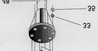
7 Assembly of Vertical Radiator Attach one 4" metal angle to the lower' tower plate and one to the upper tower plate using two (2) 1/4"-20 x 3/4" screws for each angle. Do not tighten the screws at this time. Select the two (2) U-bolts and spacer insulators and place them in the holes provided on the 4" metal angles attached to the top tower section. See - Figure 6. Select the 2" x 75" length of aluminum tubing and place the two (2) 2" ID x 3 7/8" insulators over the end of the tubing which has the metal sleeves inserted in it. Adjust the insulators so that they are approximately 28 3/8" apart, with the bottom one approximately 1 1/2" from the end of the tubing (the end with the metal sleeve). m-1825-c- NOTE: THE ASSEMBLY OF THE ANGLES, INSULATOR SPACERS AND U-BOLTS AND ATTACHMENT TO THE UPPER AND LOWER TOWER PLATES IS IDENTICAL. Item No. Description Item No. Description 7 Angle, vertical element, 1" x 1" x 4" 38 U-Bolt, 5/16" x 3" x 3 11/16" 17 Insulator, 2" I.D. x 3 7/8" 39 Lockwasher, split, 5/16", stainless steel 26 Bolt, 1/4"-20 x 3/4", hex head, stainless steel 40 Nut, 5/16"-18, hex 33 Lockwasher, 1/4", internal, stainless steel 58 Insulator, vertical element spacer, 1" x 35 Nut, 1/4"-20, hex, stainless steel 61 Assembly, tube with dowel, 2" x 75" Figure 6 Top Element Installation
8 Slide the 2" x 75" length of tubing (the end with the insulators attached) through the upper and lower plate of the top tower section as shown in Figure 6. Do not tighten the U-bolts Select the 2" x 51" section of tubing and slip the drilled end over the swaged end, of the 2" x 75" piece of tubing. Align the holes and secure with the 1/4"-20 x 2 1/2" screw, nut and lockwasher as shown in Figure 7. Select the reducer clamps and install on the end of the 2" tubing, using #10 x 1/2" screws, lockwashers and nuts. Do not tighten at this time. Carefully adjust the partially assembled vertical radiator until you measure 90 1/2" from the top edge of the top tower plate to the top edge of the reducer clamp. Refer to Figure 7. Position the two insulators on the 2" tubing as shown in Figure 6, then tighten the U-bolts evenly. The insulators must be positioned as shown to properly insulate the tubing section from the tower. Slide the metal angles in the elongated holes to position the tubing section until the tube is perfectly aligned with the axis of the tower. Tighten the screws securely! NOTE: You may wish to assemble the remainder of the vertical radiator separately and install on the antenna immediately before raising the antenna to its vertical position. This will avoid allowing the tubing to droop and permanently "set" in this condition. Select a #10 tubing clamp and slip it over the end of the 1 1/8" tube. Refer to Figure 5A for proper placement. Select the 7/8" x 72" piece of tubing and slip the unswaged end into the swaged end of the 1 1/8" tube. Measure 64 1/2" (163.8 cm) from the end of the 1 1/8" tubing to the end of the 7/8" tubing. Tighten the clamp. See Figure 7. Slip a #6 tubing clamp over the end of the 7/8" tubing. Tighten slightly. Select the 5/8" x 48" piece of tubing and slip the unswaged end into the 7/8" tubing. Measure 42" (106.7 cm) from the end of the 7/8" tube to the end of the 5/8" tube. See Figure 7. Slip a #6 tubing clamp over the end of the 5/8" tubing. Tighten slightly. Select the 7/16" x 68" piece of tubing and slip it into the 5/8" tube. Measure 66" (167.6 cm) from the end of the 5/8" tube to the end of the 7/16" tube. See Figure 7. Check the overall dimension of the vertical radiator. It should be 27'9 3/8" (3.47 m) from the top of the upper tower plate to the end of the radiator. If it is not, adjust the 7/16" tubing accordingly. Now tighten the compression clamps securely. Place a 7/16" caplug on the end of the vertical radiator. Select the 1 1/4" x 48" piece of tubing, mark at 9" from the end and slip it 9" into the 2" tube assembled in the tower, so that 36 5/8" (93.02 cm) remain exposed above the reducer clamp. See Figure 7. Select a #16 tubing clamp and slip it over the end of the 1 1/4" tube. Select the 1 1/8" x 38" tube and insert it into the 1 1/4" tube so the swaged end is 33 3/4" (85.72 cm) from the end of the 1 1/4" tube. See Figure 7.


9 No. Description No. Description 3 Clamp, reducer, 2" to 11/4", formed 33 Lockwasher, internal, 1/4", stainless 8 Tube, 7116" x 68" 35 Nut, 1/4"-20, hex, stainless steel 10 Tube, 5/8" x 48", swaged 51 Clamp, #6 tubing, stainless steel 12 Tube, 7/8" x 72", swaged 52 Clamp, #10 tubing, stainless steel 13 Tube, 1 1/8" x 38", swaged 53 Clamp, #16 tubing, stainless steel 14 Tube, 11/4" x 48", slotted 56 Caplug, 7/16", black 19 Bolt, #10-24 x 1/2", hex head, stainless steel 61 Tube Assembly with dowel, 2" x 75" 23 Lockwasher, internal, #10, stainless steel 62 Tube/Shim Assembly, 2" x 51" 24 Nut, #10-24, hex, stainless steel 32 Bolt, 1/4"-20 x 2 1/2", hex head,stainless steel Figure 7 Vertical Radiator Assembly
10 Installation of 15-Meter Stub Select a 7/16 x 60 piece of tubing and fasten one end to one leg of the base tower section using the clamps and shorting strap, as shown in Figure 8. Position the stub 67 (see Figure 16) from the bottom edge of the tower leg to the bottom edge of the 7/16 tube. Refer to Figure 8 for dimensions and Figure 10 for installation of clamps and shorting strap. Assemble another leg clamp, insulator and splice and install the second 7/16 x 60 section of tubing onto the 15-meter stub as shown in Figure 8. Install a leg clamp, insulator and tubing clamp Installation of 10-Meter Stub Select the remaining 7/16 x 60 piece of tubing and fasten one end to one of the remaining tower legs, as shown in Figure 9, using a set of leg clamps and a,shorting strap. Position the bottom edge of the stub 160 (see Figure 16) from the bottom edge of the lower tower leg. Refer to Figure 9 for dimensions and Figure 10 for installation of the clamps and shorting strap. Select the 7/16 x 38 section of tubing and install as shown in Figures 9 and 10. Install a leg clamp, insulator and tubing clamp Select the 5/16 x 23 section of tubing and slip it into the 7/16 tuba. Adjust to either Phone (19 ) or CW (21-1/4 ) dimension as shown in Figure 8. Install a ½ compression clamp, line up the screw with the hole on the 7/16 tube and tighten securely. NOTE: Typical VSWR curves are shown in Figure 16. The 10- and 15-meter stubs require two settings to cover the bands with less than 2:1 VSWR. Use the VSWR curves to help you decide which setting is best for your particular application. Place stub. 5/16 caplug on the end of the 15-meter Select the 5/16 x 9-1/2 section of tubing and slip it into the 7/16 tubing. Adjust for Phone (3 ) or CW (5 ) dimension as shown in Figure 9. Refer to Figure 16, VSWR Charts. Install a ½ compression clamp, line up the screw with the hole on the 7/16 tube and tighten NOTE: The 10-and 15-meter stubs can be set independently. One can be set for CW and one for Phone, or they can both be adjusted for the same mode. If you wish to adjust a stub for any particular frequency within an band, this can be done experimentally. Place a 5/16 caplug on the end of the 10-meter stub.


11 Item No. Description Item No. Description 5 Tube, 5/16 x Clamp, tubing, 7/16 I.D. 9 Tube, 7/16 x Strap, shorting, 5/8.x 1 ½ 27 Bolt. ¼ -20 x 1, hex head, stainless steel 45 Clamp, leg, 5/8 x 3 ½, formed 29 Bolt, ¼ -20 x 1 ½, hex head, stainless steel 46 Clamp, compression, ½ 30 Bolt, ¼ -20 x 13/4, hex head, stainless steel 49 Element Splice 33 Lockwasher, internal, ¼, stainless steel 55 Caplug, 5/16 35 Nut, ¼ -20, hex, stainless steel 57 Insulator, decoupling stub, 5/8 x 2 Figure 8 / 15-Meter Stub


12 Item# Description Item# Description 4 Tube, 5/16 x 9 ½ 43 Clamp, tubing, 7/16 I.D. 6 Tube, 7/16 x Strap, shorting, 5/8 x 1 ½ 9 Tube, 7/16 x Clamp, leg, 5/8 x 3 ½, formed 27 Bolt, ¼ -20 x 1, hex head, stainless steel 46 Clamp, compression, ½ 29 Bolt, ¼ -20 x 1 ½, hex head, stnls steel 49 Element Splice 33 Lockwasher, internal, ¼, stainless steel 55 Caplug, 5/16 35 Nut, ¼ -20 hex stainless steel 57 Insulator, decoupling stub, 5/8 x 2 15/16 Figure 9 10-Meter Stub
 to the tower leg. The braces on tower leg may interfere with this installation.")
13 Item# Description 29 Bolt, ¼ -20 x 1 ½, hex head, stainless steel 33 Lockwasher, internal, ¼ stainless steel 35 Nut, ¼ -20, hex, stainless steel 44 Strap, shorting, 5/8 x 1 ½ 45 Clamp, leg, 5/8 x 3 ½, formed 57 Insulator, decoupling stub, 5/8 x 2 15/16 *Note: When installing the Tower leg clamps (Item 45, PN: ) to the tower leg. The braces on tower leg may interfere with this installation. If so, move the leg clamps up or down to a spot where it is clear from the tower leg. Figure 10 Tower Leg Clamp Installation of 40-Meter Stub NOTE: Each stub must be attached to a separate tower leg. The 40-meter stub (now being assembled) must be attached to the very top of the tower section. See Figure 11. Select the 5/8" x 24" tube and install it on tower using two leg clamps and two shorting straps spaced 5 1/2" apart, as shown in Figure 11. Slip a #6 tubing clamp onto the 5/8" tube. Tighten slightly. Select the 7/16" x 68" tube and slip it into the 5/8" tube. Measure 90" for both Phone and CW, as shown in Figure 11, then tighten the compression clamp securely. Place a 7/16" caplug on the top of the 40-meter stub. NOTE: The higher tubing clamp can be loosened and the lower shorting strap hinged to bring the 40-meter stub into a vertical position.


14 Item# Description 8 Tube, 7/16 x Tube, 5/8 x 24, swaged 20 Bolt, #10-24 x 1, hex head, stainless steel 23 Lockwasher, internal, #10, stainless steel 24 Nut, #10-24, hex, stainless steel 29 Bolt, ¼ -20 x 1 ½, hex head, stainless steel 33 Lockwasher, internal, ¼ stainless steel 35 Nut, ¼ -20, hex, stainless steel 44 Strap, shorting, 5/8 x 1 ½ 45 Clamp, leg, 5/8 x 3 ½ formed 47 Clamp, tubing, 5/8 I.D. 51 Clamp, stainless steel, #6 tubing 56 Caplug, 7/16, black Figure Meter Stub

15 Installation of 80-Meter Wire Select the 80-meter wire and install it in the center of the tower with the looped end at the top of the tower. Select the 3/8" spacer tube and attach the 80meter wire to the 2'.' tube as shown in Figure 12. Install the eyebolt at the tower base assembly as shown in Figure 12. Adjust for maximum height. The 80-meter wire will attach to this eyebolt after the tower is tilted into place. Item No Description Bolt, #10-24 x 1", hex head, stainless steel Bolt, #10-24 x 2 1/2", hex head, stainless steel Flatwasher, #10, stainless steel Lockwasher, internal, #10, stainless steel Nut, #10-24, hex, stainless steel Lockwasher, intemal, 1/4", stainless steel Nut, 1/4"-20, hex, stainless steel Eyebolt, 1/4" x 1 1/2" x 1/2" Tube, spacer, 3/8" x 17/8" 80-Meter Wire Assembly Tube Assembly with dowel, 2" x 75" Figure Meter Wire Installation
 it will be necessary to add a")


16 NOTE: To cover the low end of 80 meters (see Figure 12) it will be necessary to add a loading coil as previously explained and shown in Figure 13. This coil can be used to extend the 80 meter band or add 160 meter operation. Figure Meter and 160 Meter Coil Installation

17 160 Meter Operation By adding one of two available kits, 160 meter operation can be added to the 18HT "Hy-Tower". these kits are available from: Hy-Gain, 308 Industrial Park Road Starkville, MS USA. Kit Number LC-160Q is a loading coil that can be added at the tower base as shown in Figure 13. This coil is four turns per inch, 3" I.D. by 10" long. After the coil is installed, the wire clip should be attached at the point that gives minimum VSWR at the frequency you wish to operate on. This coil should be bypassed when operating on 20 or 75 meters. WARNING When using the LC-160Q Modification Kit added to the 18-HT on 160 meters, do not exceed 150 watts output power (300 W P.E.P. out). Power levels in excess of this limit will cause the antenna to arc. Kit Number MK-160 is a 40 meter trap and wire assembly that can be added at the top of the tower as shown in Figure 17. This kit will provide a greater band width and a higher power rating than the LC-160Q. It also provides fully automatic band switching from 160 through 10 meters. Erection of Tower Install the tower legs with hinges attached onto the base assembly. Do not tighten screws at this time. WARNING When installing your system, take extreme care to avoid any accidental contact with power lines or overhead obstructions. Failure to exercise this could result in Lift the antenna and walk it into a vertical position. Install the remaining leg brace and bolt the leg to the base assembly as shown in Figure 14. Tighten all screws securely. Insert the 80-meter wire through the eyebolt installed at the tower base. Wrap the wire around itself several times to insure a good tight connection. Solder the connection for the best electrical connection. Adjust the eyebolt until the wire is taut. Attach the solder lug on the 80-meter wire to the tower base assembly as shown in Figure 14. is Item No. Description 15 Plate, leg backing, 3/4" x 5 3/4" 16 Hinge, tower formed Bolt, 3/8"-16 x 1", hex head, stainless steel 65 Lockwasher, internal, 3/8", stainless steel Nut, 3/8"-16, hex head, stainless steel Figure 14 Tower Leg Attachment to Base
 for a good Attach each rod to a pip leg using #10 or larger copper wire (not supplied).")
18 Feedline Attachment and Grounding Install two ground rods at each tower leg. Space them 24" from the leg with 18" between the two rods as shown in Figure 15. Use 1/2" x 8' copper clad steel rods (not supplied) for a good Attach each rod to a pip leg using #10 or larger copper wire (not supplied).. Now connect the three pipe legs together as shown in Figure 15. Strip your coaxial cable and attach the center conductor to the tower base using the hole provided as shown in Figure 15. Attach the braid to a pipe leg. Cover the exposed coax cable dielectric to prevent U.V. cracking. Weatherproof the coaxial cable using Coax- Seal or some similar substance to prevent water from entering and ruining the coax. The overall efficiency of the 18-HT -S can be improved by adding a radial system. The next section describes how to install a radial system. Coax-Seal is a registered trademark of Universal Electronics, Inc. Item No Description Bolt, 1/4"-20 x 1 1/2", hex head, stainless steel Flatwasher, 1/4", stainless steel Nut, 1/4"-20, hex, stainless steel Nut, 1/4"-20, square, stainless steel Clamp, compression, 1 1/4" Figure 15 Ground Rod Installation
19 Installation of Radials There is no need to make radials exactly 1/4" wavelength long for the 18-HT-S Hy-Tower. In fact, the only case where you should have 1/4" wavelength radials would be for approximately 90 radials. This differs rather dramatically from the case of a Ground-Plane antenna where resonant radials are installed above ground. Since the radials of a Ground-Mounted vertical are actually on, if not in, the ground, they are coupled by capacitance or conduction to the ground, and thus resonance effects are not important. Basically, the function of radials is to provide a low-loss return path for ground currents. The reason that short radials are sufficient, when few are used, is that at the perimeter of the circle to which the ground system extends, the radials are sufficiently spread apart. Most of the return currents are already in the ground between the radials rather than in the radials themselves. As more radials are added, the spaces between them are Since the 18-HT -S Hy-Tower is a multi-band, vertical antenna, the radial system should be optimized on the lowest frequency you plan to use. Higher frequencies will benefit equally from the ground system, while lower frequencies will not show as much To determine the optimum radial installation for your 18-HTS Hy-Tower, you must first decide what is the limiting factor for your 1. Cost of radial i 2. Land available for radials 3. Efficiency of your antenna Table 1 shows some various ground system configurations. System A is the least costly and the least efficient. System F is the most expensive, takes the most land and is the most efficient.
20 A B C D E F Number of Radials Length of each radial in wavelengths Spacing of radials in degrees TOTAL length of radial wire installed, in wavelengths Power gain (db) due to increased efficiency Radiation take-off angle in degrees Feed-point impedance in ohms with a 1/4-wave radiating element Radial end buried YES YES YES NO NO NO Table 1 Optimum Ground System Configuration NOTE: TABLE 1 is optimized for poor earth conditions. Conductivity = Siemens/meter and the Relative Dielectric Constant = 7. Better earth conditions will increase the power gain and lower the take-off angle for systems A-D. Systems E and F will not be affected as much, except for additional lowering of the take-off angle by as much as 5 to 8 degrees. See pages of "QST" June, 1985 for more information on radial systems for verticals.

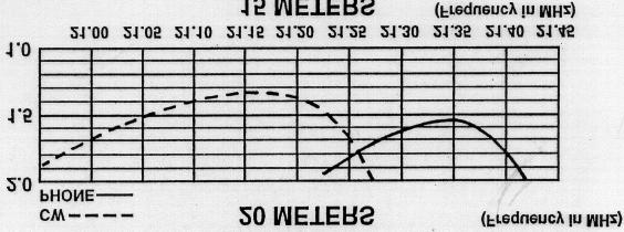
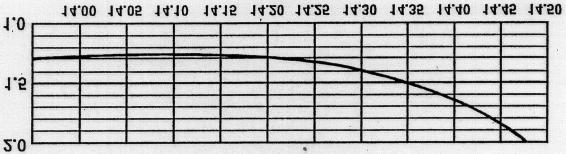
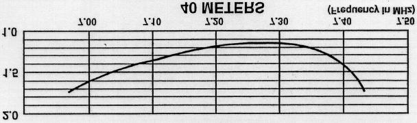
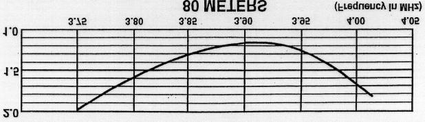
21 Figure 16 VSWR Charts


22 Figure 17 Overall View of 18-HT-S
23 PARTS LIST NOTE: Item numbers may not necessarily be in numerical sequence and may appear more than one time, depending on how often a part is used or identical parts being placed in different parts packs. Item Part No. Description Qty No Tower, modified, BX Carton, tubing and parts Clamp, Reducer, 2" to 1 1/4",formed Tube,5/16"x 9 1/ Tube,5/16"x 23" Tube, 7/16" x Angle, Vertical Element, 1 x 1 x Tube, 7/16" x Tube, 7/16" x Tube, swaged, 5/8" x 48" Tube, swaged, 5/8 x 24" Tube, swaged, 7/8" x 72" Tube, swaged, 1 1/8" x 38" Tube, slotted, 1 1/4" x 48" Plate, Leg Backing, ¾ x 5 3/4" Hinge, Tower, formed Insulator, 2 I.D. x 3 7/ Parts Pack, 182S, Hardware Bolt, hex heal #10-24 x 1/2", stainless steel Bolt, hex head, #10-24 x 1", stainless steel...: Bolt, hex head, #10-24 x 2 1/2", stainless steel Flatwasher, #10, stainless steel Lockwasher, internal, #10, stainless steel Nut, hex, #10-24, stainless steel Nut, square, #10-24, stainless steel Bolt, hex head, 1/4"-20 x 3/4", stainless steel Bolt, hex head, 1/4"-20 x 1", stainless steel Bolt, hex head, 1/4"-20 x 1 ½ stainless steel Bolt, hex head, 1/4"-20 x 1 3/4", stainless steel....: Bolt, hex head, 1/4"-20 x 2, stainless steel Bolt, hex head, 1/4"-20 x 2 1/2", stainless steel Lockwasher, internal, 1/4", stainless steel Flatwasher, 1/4", stainless steel...: Nut, hex, 1/4"-20, stainless steel Nut, square, 1/4"-20 stainless steel...: Eyebolt, 1/4" x 1 1/2" x½ Lockwasher; split, 5116", stainless steel Nut, hex, 5/ Bolt, hex head, 3/8"-115 it 1", stainless steel Lockwasher, internal, 3/8", stainless steel Nut, hex 3/8"-16 stainless steel Parts Pack, tower section hardware Nut; hex 3/8" -16, stainless steel Bolt, hex head, 3/8"-16 x 3/4", stainless steel Lockwasher, internal, 3/8", stainless steel... 12

24 PARTS LIST (continued) Item# Part # Description Carton, tubing and parts (continued) Parts Pack 182S, Clamps U-Bolt, 5/16" x3" x 3 11/16"...2 Clamp, Tubing, 7/16" LD Strap, Shorting, 5/8" x 1 1/2"...6 Clamp, Leg, formed 5/8" x 3 1/2" Clamp, Compression, 1/2" Clamp, Tubing 5/8" LD Clamp, Compression, 1 1/4" Element Splice Tube, Spacer 3/8" x 17/8 "...1 Clamp, #6 Tubing, stainless steel Clamp, #10 Tubing, stainless steel Clamp, #16 Tubing, stainless steel (Not Used) Caplug, 5/ Caplug, 7/16", black Insulator, decoupling stub, 5/8" x 2 15/16" Insulator, Vertical Element Spacer, l" x 4" Base Tube Assembly Wire Assembly, 80 Meter Tube Assembly with dowel, 2" x 75" Tube/Shim Assembly, 2" x Base Assembly "B Base Assembly "A...1 Converting English Measurements to Metric 1 inch (1") = 2.54 cm Use this scale to identify lengths of bolts, 1foot (1')=30.48 cm diameters of tubes, etc.. The English inch (1") and foot (1') can be converted in this way. Example: 42" x 2.54= FRACTION AND METRIC EQUIVALENTS FOR ONE INCH Fractional Fractional Inch Millimeters Inch Millimeters 1/ / / / / / / / / / / / / / /


25 The Hy-tower base assembly has been changed. Substitute this drawing for figure 2 on page 3.

 triangle. Install two spacers between the triangle tab and the tower leg.")
 triangle, Make sure that both of")
26 The tower plates inside the Hy-tower have been improved, The new plates are made from stainless steel. Install the lower plate as shown in the diagram. One X has been left out of the top section to allow for easy installment of the lower ( larger ) triangle. Install two spacers between the triangle tab and the tower leg. The upper plate should be installed with the triangle tabs on the outside of the tower legs. Use the 1/4-20x 1/2 bolts for the upper (small) triangle, Make sure that both of the triangles are oriented the same way.

27 ADDENDUM ENGINEERING REPORT PHASED MULTI-BAND VERTICALS for ADDITIONAL GAIN and LOW ANGLE RADIATION Phased Patterns INTRODUCTION The following Hy-Gain verticals are well adapted for the phasing arrangements shown in this report. AV-18HT AV-18VS/18AVT AV-14AVQ AV-12AVQ MODEL 18HT-S HY-TOWER The 18HT-S is a multi-band vertical antenna with automatic band selection of meters by means of a unique stub decoupling system. The Hy-Tower with a base loading coil operates efficiently on 160 meters. The system is foolproof, fed directly with a single 50 ohm coax. No guys are required for the 24 feet high, self-supporting tower. The top mast extends the height to 50 feet. Two units make an ideal phased array. MODEL 18AVT/WB-S VERTICAL The 18AVT/WB-S is a multi-band trap vertical for 10 through 80 meters. It is completely factory pre-tuned and exhibits an extremely low angle DX radiation pattern. It is easy to assemble, light weight which one man can install. A single 50 ohm coaxial feedline is required. Two or three 18AVT/WB-S's make an excellent phased array.
28 MODEL 14AVQ/WB-S The 14AVQ/WB-S is a self supporting multiband trap vertical for 10 through 40 meters and is completely factory pre-tuned. It is the world's most popular ham antenna with an overall height of 19 feet. The antenna is thoroughly weatherproofed and has a low angle DX radiation pattern. It may be ground mounted or installed on "Roof Top" with a radial system. MODEL 12AVQ The 12AVQ is a self supporting 13 1/2 foot multi-band trap vertical for 10, 15 and 20 meters. Completely factory pre-tuned with SWR of 2:1 or less with a low angle DX radiation pattern. The antenna has a new fiberglass impregnated styron base insulator. It may be ground mounted with earth acting as the "image antenna" or installed on the roof using a radial system. DESCRIPTION Increased activity on 80 and 40 meters has created a need for an antenna with power gain and directivity. Doublet and long wire antennas are no longer effective due to increased QRM. At these low frequencies, the radiation system must be lengthy and height above ground is extremely important to obtain the "low" angle of radiation needed for DX. Beams are excellent, but require a large supporting tower and "hefty" rotating system. Inverted V dipoles and slopers require a large tower and plenty of property. The vertical "phased array", the answer for "DX" on these frequencies combine gain, directivity and low angle radiation, the three most important DX factors in a communication installation. The vertical is well known for its low angle characteristics. When you combine two identical verticals, properly spaced and phased, the resultant is a concentrated low angle of energy and a power gain. These antennas can be so arranged to give a definite effect on either one or two favorite bands or all band coverage with some pattern compromise and slight loss of gain. The following data was experimentally derived on the Telex/Hy-Gain test range. Due to the many factors that vary and influence the performance of an antenna, such as grounding and close proximity of surrounding objects, etc., Telex/Hy-Gain cannot guarantee an installation to perform or exhibit the same characteristics as outlined in this report. However, many Amateurs are now successfully using these arrangements. Commercial broadcast stations have been using a similar phasing arrangement for years. Part 1 - SINGLE BAND BI-DIRECTIONAL ARRAY (Four Quadrants) THEORY' OF OPERATION Two identical vertical antennas can be installed as a phased array. When excited by RF energy, gain is achieved by control of the directional pattern. This direction pattern control results in added gain by sharpening lobe patterns and concentrating the radiated energy at very low angles. Signal flutter is reduced and reception is vastly improved. Phased arrays will reduce installation height requirements and still maintain low angle radiation. Most effective spacing for a bi-directional array is 1/2 wave length. When two verticals are excited in phase the radiation is broadside to the plane of the verticals, offering substantial gain and bi-directional characteristics. Side nulls offer excellent signal cancellation to the undesired direction.

29 "BROADSIDE" GAIN 3.86 When excited "out of phase" these same verticals can be made to give an "end fire" or bidirectional pattern in the opposite direction through the plane of the verticals. This then nulls out signals in the opposite directions. More gain is exhibited by the broadside pattern over the "end fire" arrangement, but the "end fire" arrangement offers a wider frontal pattern. Both arrangements offer an excellent advantage over a single vertical since either phasing combination exhibits noticeable signal gain with side attenuation of undesired signals. This added gain and low angle vertical directivity is the advantage of the phased array. "ENDFIRE" GAIN 23 db Phased verticals may be spaced either one quarter wave or one half wave depending upon gain and directional characteristics. The nulls of the phased array are extremely sharp and very pronounced. Typical arrangements of phased arrays and their electrical specifications are illustrated below. When feedline "A" is the same length as feedline "B"the currents arrive at the base of each antenna at the same time, giving the "inphase" broadside pattern. When feedline "A" is 1/2" wave length shorter than feedline '8"the current arrives at antenna."x" 1/2 wave length sooner (180 degrees) than at antenna "Y" giving the 'out of phase" end fire pattern. Figure 1

30 ELECTRICAL SPECIFICATIONS Broadside End Fire Pattern Width, half power points 60 degrees 80 degrees Gain over single vertical 3.86 db 2.3 db Side Attenuation 30 db 20 db Impedance 50 Ohms 50 Ohms Directional Characteristics Bi-Direcitonal Bi-Directional Figure 2. Ty p ical Installation Phased (2) 18 HT 40 Meters 7200 KHz Design Frequency
31 CARDIOID ARRAY (Uni-directional) When two or three identical verticals are excited directly and fed 90 degrees out of phase with a spacing of 1/4 wave length, a cardioid pattern results. This pattern may be switched in either direction. By inserting a 1/4 wave length delay line the antenna will "fire" or be directive to that particular element. TWO VERTICALS Figure 3 Cardioid-Unidirectional With Two Selectable Directions

32 The beam pattern for two 1/4 wave length verticals will be approximately 120 degrees. An arrangement of three switchable verticals gives a 60 degree pattern in six selectable directions. TOP VIEW - 3VERTICALS Figure Cardioid Arrangement
33 ELECTRICAL SPECIFICATIONS: Two Phased Verticals Three Phased Verticals Pattern Width, half power points 120 degrees 60 degrees Gain over single vertical 4.5 db 4.5 db Side attenuation 20 db 20 db Rear attenuation 30 db 30 db Impedance 50 Ohms 50 Ohms Directional Characteristics Uni-directional Uni-directional VSWR: Exceptionally low SWR is present with a phased array. If phasing lines are correctly measured and the terminal impedance of each antenna is very close to 50 Ohms: Typical SWR: Broadside 1.2:1, Endfire 1.4:1, Cardioid 1.2:1. PHASING LINES: The 1/4 and 1/2 wave transformers, identified as L3, L4 and L5 are calculated from the lowing formula: 1/4 wave x vel. vel. factor - reg. coax. frequency f (in KHz) 0.66 EXAMPLE: 1/4 wave at 7200 KHz = / 7200 = /4 wave = ft x PART 2 - MULTI-BAND OPERATION MULTI-BANDING Multi-banding is easily accomplished by choice spacing two identical verticals. (refer to charts A,B, and C and associated Figures 1 through 5) Switchable 1/4 wave length and 1/2 wave length phasing cables must be employed for each band. These cables can be placed in the station in any suitable fashion along with a manual switching arrangement or relay system. RADIATION PATTERN: Consideration must be given to the fact that 1/2 wave spacing (optional) is ideal for phasing. When multi-banding with close and wide spacing, compromise radiation patterns must be expected. In most cases a choice spacing serves 3 bands most effectively with good directional characteristics, added gain and low angle performance.
34 OPTIONAL SPACING Various antenna spacings may be selected from charts A, B, and C, for single band, duo band or multi-band arrangements. Associated radiations patterns for a specific spacing is shown in Figures 1 through 5 for each band. If the 3/4 wave length patterns are not desirable, a single vertical only can be switched in use to obtain an omnl-directional pattern. INSTALLATION The vertical antenna requires a minimum amount of space. Ground mounted or elevated arrays are easily installed. Antenna placement and orientation is a most important factor when planning maximum effectiveness is desired directions. Each vertical should be installed in the clear relatively free of surrounding objects in order to maintain its design 50 Ohm terminal impedance. Each antenna must be mounted at the same height on or above ground and be so arranged according to their radiation pattern to offer desired directivity. The phased array is primarily designed for long range and DX communications. In cases where close and medium distance contacts are hampered by the array's low angle characteristics and a higher angle is required, switching arrangements can select one vertical for this coverage. SWITCHES & CONNECTORS Low loss constant impedance type coaxial switches and connectors should be used when splicing phasing lines. B&W multi-position, single or multi-gang coaxial switches with Amphenol coaxial cable and "T' connectors are recommended. FIELD TESTS Actual field tests comparing one vertical to the phased array results in doubling the receivers sensitivity and offering up to 12 db of signal increase. An attenuation of up to 30 db is noticeable on the phased verticals with half wave spacing. With quarter wave spacing, up to 20 db cardioid, and 30 db front-to-back attenuation can be obtained. "End Fire" directivity offers a larger area of radiation at slightly reduced gain as compared to the broadside arrangement. The "broadside" arrangement is recommended for communications at greater distances whereas the "endfire" arrangement would be so arranged to cover a larger area of communications. Special attention to the coax phasing line lengths and their proper placement is of utmost importance.
 the SWR may be somewhat higher than 1/2 wave spacing. SW3 selects direction B. 40 meters all switches in position 1 selects Bi- Directional patterns.")
35 A. 80 meter bi-directional pattern (all SW positions 3) refer to Figure 1, Part 2 "Radiation Patterns" NOTE: Due to close electrical spacing (1/4 wave) on 80 meters for Broadside (position 1) and Endfire (position 2) the SWR may be somewhat higher than 1/2 wave spacing. SW3 selects direction B. 40 meters all switches in position 1 selects Bi- Directional patterns. Use SW2 for broadside (position 1) Endfire (position 2). C. All switches in position 2 selects cardioid pattern. SW4 selects direction of cardioid pattern. NOTE: All connecting lines are exaggerated in length. These lines must be direct and short as with any coax hook-up practice. Figure 5 Typical installation (2) 18HT-S Phased for 80 and 40 Meters Selectable Broadside and Endfire Patters on 40 Meters Selectable Broadside and Endfire Patterns on 80 Meters Selectable 2 Directions Cardioid on 80 Meters


36 Spacing Single Band Arrangement 125' 80 66' 40 33' 20 Dual Band Arrangement 66' ' ' Multi-band Arrangement 33' ' Note: Corralate Patterns to spacing used in installation Figure 6 Radiation Patterns. Typical Spacing For Broadside And Endfire Arrangements
37 LIMITED WARRANTY Hy-Gain Warrants to the original owner of this product, if manufactured by Hy-Gain and purchased from an authorized dealer or directly from Hy-Gain to be free from defects in material and workmanship for a period of 12 months for rotator products and 24 months for antenna products from date of purchase provided the following terms of this warranty are satisfied. 1. The purchaser must retain the dated proof-of-purchase (bill of sale, canceled check, credit card or money order receipt, etc.) describing the product to establish the validity of the warranty claim and submit the original or machine reproduction of such proof of-purchase to Hy-Gain at the time of warranty service. Hy-Gain shall have the discretion to deny warranty without dated proof-of-purchase. Any evidence of alteration, erasure, or forgery shall be cause to void any and all warranty terms immediately. 2. Hy-Gain agrees to repair or replace at Hy-Gain s option without charge to the original owner any defective product under warranty, provided the product is returned postage prepaid to Hy-Gain with a personal check, cashiers check, or money order for $8.00 covering postage and handling. 3. Under no circumstances is Hy-Gain liable for consequential damages to person or property by the use of any Hy-Gain products. 4. Out-of-warranty Service: Hy-Gain will repair any out-of-warranty product provided the unit is shipped prepaid. All repaired units will be shipped COD to the owner. Repair charges will be added to the COD fee unless other arrangements are made. 5. This warranty is given in lieu of any other warranty expressed or implied. 6. Hy-Gain reserves the right to make changes or improvements in design or manufacture without incurring any obligation to install such changes upon any of the products previously manufactured. 7. All Hy-Gain products to be serviced in-warranty or out-of-warranty should be addressed to hy-gain, 308 Industrial Park Road, Mississippi 39759, USA and must be accompanied by a letter describing the problem in detail along with a copy of your dated proof-of-purchase. 8. This warranty gives you specific rights, and you may also have other rights which vary from state to state.
AV-12AVQ Triband HF Vertical 10, 15, 20-Meter INSTRUCTION MANUAL
 308 Industrial Park Starkville, MS 39759 USA Ph: (662) 323-9538 FAX: (662) 323-6551 AV-12AVQ Triband HF Vertical 10, 15, 20-Meter INSTRUCTION MANUAL General Description This vertical antenna is designed
INSTRUCTION MANUAL. Model 18AVQII Five Band Vertical Antenna 10, 15, 20, 40, 80 Meter. General Description. Theory of Operation
 Model 18AVQII Five Band Vertical Antenna 10, 15, 20, 40, 80 Meter 308 Industrial Park Road Starkville, MS 39759 (662) 323-9538 Fax: (662) 323-5803 INSTRUCTION MANUAL General Description The Hy-Gain 18AVQII
INSTRUCTION MANUAL. Specifications Electrical. Front-To-Back Ratio VSWR at Resonance Less than 1.5:1 Nominal Impedance. Mechanical
 300 Industrial Park Road, Starkville, MS 39759 Ph: (662) 323-8538 FAX: (662) 323-6551 TH-3JRS Tri-band HF 3 Elements Beam Covers 10, 15 and 20 Meters INSTRUCTION MANUAL WARNING Installation of this product
INSTRUCTION MANUAL. Specifications Mechanical. 1 5/8 to 2 1/16 O.D. (41mm to 52mm)
") 308 Industrial Park Road Starkville, MS 39759 USA Ph: (662) 323-9538 FAX: (662) 323- General Description Model VB-25FM 2-Meter 5 Elements Beam INSTRUCTION MANUAL This antenna is a 5-element, 2-meter beam
308 Industrial Park Road Starkville, MS 39759 USA Ph: (662) 323-9538 FAX: (662) 323- General Description Model VB-25FM 2-Meter 5 Elements Beam INSTRUCTION MANUAL This antenna is a 5-element, 2-meter beam
INSTRUCTION MANUAL V-42R. Dual Band Collinear Gain Vertical for MHz and GENERAL DESCRIPTION
 308 Industrial Park Road, Starkville, MS 39759 USA Ph: (662) 323-9538 FAX: (662) 323-6551 V-42R Dual Band Collinear Gain Vertical for 144-148 MHz and 436-450 INSTRUCTION MANUAL GENERAL DESCRIPTION The
INSTRUCTION MANUAL VB-66DX. 6-Meter 6-Element Beam. Preparation For Assembly. General Description
 VB-66DX 308 Industrial Park Road Starkville, MS 39759 USA Ph: (662) 323-9538 FAX: (662) 323-6551 6-Meter 6-Element Beam INSTRUCTION MANUAL General Description The Hy-Gain Model 66DX is a full sized 6-
LJ element beam for 10 or 12 meters INSTRUCTION MANUAL. CAUTION: Read All Instructions Before Operating Equipment
 LJ-113 3 element beam for 10 or 1 meters INSTRUCTION MANUAL CAUTION: Read All Instructions Before Operating Equipment 308 Industrial Park Road Starkville, MS 39759 USA Tel: 66-33-9538 Fax: 66-33-6551 VERSION
INSTRUCTION MANUAL. Model 18AVQII Five Band Vertical Antenna 10, 15, 20, 40, 80 Meter
 Model 18AVQII Five Band Vertical Antenna 10, 15, 20, 40, 80 Meter 308 Industrial Park Road Starkville, MS 39759 (662) 323-9538 Fax: (662) 323-5803 INSTRUCTION MANUAL General Description The Hy-Gain 18AVQII
Model VB-23FM 2-Meter 3-Element Beam
 308 Industrial Park Road Starkville, MS 39759 USA Ph: (662) 323-9538 FAX: (662) Model VB-23FM 2-Meter 3-Element Beam [ INSTRUCTION MANUAL Figure 1 Overall View and Boom Detail GENERAL DESCRIPTION This
INSTRUCTION MANUAL. Model BN-4000B. High Power Balun for Beams with Type SO-239. Construction. General Description. Mounting on Boom or Mast
 308 Industrial Park Starkville, MS 39759 USA Ph: (662) 323-9538 FAX: (662) 323 6551 Model BN-4000B High Power Balun for Beams with Type SO-239 INSTRUCTION MANUAL General Description The BN-4000 is a current-type
MFJ-1835K34 40,30 METER ADD ON KIT FOR THE MFJ-1835 COBWEB ANTENNA INSTRUCTION MANUAL. CAUTION: Read All Instructions Before Operating Equipment
 MFJ-1835K34 40,30 METER ADD ON KIT FOR THE MFJ-1835 COBWEB ANTENNA INSTRUCTION MANUAL CAUTION: Read All Instructions Before Operating Equipment 300 Industrial Park Road Starkville, MS 39759 USA Tel: 662-323-5869
MFJ-2100 INSTRUCTION MANUAL. CAUTION: Read All Instructions Before Operating Equipment
 MFJ-2100 INSTRUCTION MANUAL CAUTION: Read All Instructions Before Operating Equipment 300 Industrial Park Road Starkville, MS 39759 USA Tel: 662-323-5869 Fax: 662-323-6551 COPYRIGHT C 2015 MFJ Enterprises
MFJ-2389 Compact 8 Band Vertical
 MFJ-2389 Compact 8 Band Vertical The MFJ-2389 is an 8 band compact vertical that is designed to operate on 80, 40, 20, 15, 10, 6, 2M, and 70CM bands. The antenna will handle 200W PEP or 50W CW HF or 150W
2014 MFJ ENTERPRISES, INC.
 Model MFJ-1907 INSTRUCTION MANUAL CAUTION: Read All Instructions Before Operating Equipment MFJ ENTERPRISES, INC. 300 Industrial Park Road Starkville, MS 39759 USA Tel: 662-323-5869 Fax: 662-323-6551 VERSION
The MFJ-1754 can be mounted on any 1" to 1 1/2" mast (conductive or non conductive.)
") INTRODUCTION: The MFJ-1754 is designed for use on the 2 meter and the 70 centimeter bands. On the 2 meter band the MFJ-1754 behaves as a vertical 1/4 wave antenna, however on 70 centimeter band the MFJ-1754
INTRODUCTION: The MFJ-1754 is designed for use on the 2 meter and the 70 centimeter bands. On the 2 meter band the MFJ-1754 behaves as a vertical 1/4 wave antenna, however on 70 centimeter band the MFJ-1754
INSTRUCTION MANUAL. DP-19PD 2-30 MHz Portable Dipole. Figure 1
 303 Industrial Park Road, Starkville, MS 39759 USA Ph: (662) 323-9533 FAX: (662) 323-6551 DP-19PD 2-30 MHz Portable Dipole INSTRUCTION MANUAL Figure 1 GENERAL DESCRIPTION The Model 19-PD is an ultra-light
MFJ ENTERPRISES, INC.
 Model MFJ-2910 INSTRUCTION MANUAL CAUTION: Read All Instructions Before Operating Equipment MFJ ENTERPRISES, INC. 300 Industrial Park Road Starkville, MS 39759 USA Tel: 662-323-5869 Fax: 662-323-6551 VERSION
DB Duo-Monoband Beam 7 - Element, 12 and 17 Meter INSTRUCTION MANUAL. General Description
 308 Industrial Park Road Starkville, MS 39759 USA Ph: (662) 323-9538 FAX: (662) 323-6551 DB- 1217 Duo-Monoband Beam 7 - Element, 12 and 17 Meter INSTRUCTION MANUAL General Description The Hy-Gain DB-1217
Installation Instructions Hustler 6-BTV Trap Vertical
 Installation Instructions Hustler 6-BTV Trap Vertical ASSEMBLY 1. Check the package contents against the parts list on page 2. 2. WARNING. Installation of this product near power lines is dangerous. For
Installation Instructions Hustler 6-BTV Trap Vertical
 Installation Instructions Hustler 6-BTV Trap Vertical ASSEMBLY 1. Check the package contents against the parts list on page 2. 2. WARNING. Installation of this product near power lines is dangerous. For
MODEL DB-1015A 10- and 15-Meter Duo-Band Antenna Order No. 330
 MODEL DB-1015A 10- and 15-Meter Duo-Band Antenna Order No. 330 HY-GAIN ELECTRONICS CORPORATION 8601 Northeast Highway 6 Lincoln, Nebraska 68505 Telephone 464-9151 Area Code 402 TABLE OF CONTENTS page SECTION
MFJ ENTERPRISES, INC.
 Model MFJ-2010 INSTRUCTION MANUAL CAUTION: Read All Instructions Before Operating Equipment MFJ ENTERPRISES, INC. 300 Industrial Park Road Starkville, MS 39759 USA Tel: 662-323-5869 Fax: 662-323-6551 VERSION
MFJ ENTERPRISES, INC.
 Model MFJ-2013 INSTRUCTION MANUAL CAUTION: Read All Instructions Before Operating Equipment MFJ ENTERPRISES, INC. 300 Industrial Park Road Starkville, MS 39759 USA Tel: 662-323-5869 Fax: 662-323-6551 VERSION
MFJ-1750/1752 2M BASE ANTENNA with 5/8 GROUND PLANE Instruction Manual
 MFJ-1750/1752 2M BASE ANTENNA with 5/8 GROUND PLANE Thank you for purchasing the MFJ-1750/1752. The 1750 is a 5/8 wave antenna designed for operation on 144-148 MHz. The 1752 is designed to operate on
TELEX. iiilhiijiri INSTRUCTION MANUAL ORDER NO. 411 TELEX COMMUNICATIONS, INC ALDRICH AVE SO. MINNEAPOLIS. MN U.SA.
 TELEX. iiilhiijiri TELEX COMMUNICATIONS, INC. 9600 ALDRICH AVE SO. MINNEAPOLIS. MN 55420 U.SA. INSTRUCTION MANUAL ORDER NO. 411 Base Station, 5-Element Beam Antenna This antenna is a five element, Citizens
TELEX, liutiiilio"i TELEX COMMUNICATIONS, INC ALDRICH AVE. SO. MINNEAPOLIS. MN USA
 TELEX, liutiiilio"i TELEX COMMUNICATIONS, INC. 9600 ALDRICH AVE. SO. MINNEAPOLIS. MN 55420 USA INSTRUCTION MANUAL ORDER NO. 410 General This antenna is a five-element, Citizens Band beam with a forward
MFJ Instruction Manual
 MFJ-1763 Thank you for purchasing the MFJ-1763 portable beam antenna. This antenna is designed for operation throughout the 2-meter band. The MFJ-1763 is shipped partially assembled, you should have received
INSTRUCTION MANUAL ORDER NO. V3R MODEL V3R. Collinear Gain Vertical for MHz
 ORDER NO. V3R MODEL V3R Collinear Gain Vertical for 216-225 MHz INSTRUCTION MANUAL General Description The new Hy-Gain V3R VHF antenna is a collinear 5/8-wave omnidirectional vertical antenna for the 216-225
MFJ ENTERPRISES, INC.
 Model MFJ-2911 INSTRUCTION MANUAL CAUTION: Read All Instructions Before Operating Equipment MFJ ENTERPRISES, INC. 300 Industrial Park Road Starkville, MS 39759 USA Tel: 662-323-5869 Fax: 662-323-6551 VERSION
INSTRUCTION MANUAL for MODEL TH6-DX "THUNDERBIRD" (389)
") INSTRUCTION MANUAL for MODEL TH6-DX "THUNDERBIRD" (389) HY-GAIN ELECTRONICS CORPORATION, N. E. Hwy #6 at Stevens Creek, Lincoln, Nebraska 65801 Telephone 434-6331 INTRODUCTION Ely-Gain's new Model TH6-DX
INSTRUCTION MANUAL for MODEL TH6-DX "THUNDERBIRD" (389) HY-GAIN ELECTRONICS CORPORATION, N. E. Hwy #6 at Stevens Creek, Lincoln, Nebraska 65801 Telephone 434-6331 INTRODUCTION Ely-Gain's new Model TH6-DX
INSTRUCTION MANUAL. Model VB-215DX MECHANICAL DESIGN GENERAL DESCRIPTION ELECTRICAL DESIGN. 2 Meter 15 Element Yagi for SSB/CW
 Model VB-215DX 2 Meter 15 Element Yagi for SSB/CW INSTRUCTION MANUAL GENERAL DESCRIPTION The Hy-Gain Model 215DX is a high performance yagi antenna for SSB/CW DXing in the Amateur 2 meter band. It features
MFJ ENTERPRISES, INC.
 Models: MFJ-1770C (10m) MFJ-1770B (15m) MFJ-1771B (17m) MFJ-1772B (20m) MFJ-1773B (30m) MFJ-1774B (40m) MFJ-1776B ( 6m) INSTRUCTION MANUAL CAUTION: Read All Instructions Before Operating Equipment MFJ
MFJ-203 Bandswitched Dip Meter
 MFJ-203 Bandswitched Dip Meter Thank you for purchasing the MFJ-203 Bandswitched Dip Meter. The MFJ-203 Bandswitched Dip Meter is a solid state bandswitched adaptation of the traditional grid dip meter.
Cushcraft. Amateur Radio Antennas DB-46M8EL. Dual band 6 and 4 Meter, 8 Element Beam Antenna INSTRUCTION MANUAL
 Cushcraft Amateur Radio Antennas DB-46M8EL Dual band 6 and 4 Meter, 8 Element Beam Antenna INSTRUCTION MANUAL CAUTION: Read All Instructions Before Operating Equipment VERSION 1B Cushcraft Amateur Radio
K1FO 12 ELEMENT 144/147 MHz YAGI
 K1FO 12 ELEMENT 144/147 MHz YAGI WARNING: INSTALLATION OF THIS PRODUCT NEAR POWER LINES IS DANGEROUS. FOR YOUR SAFETY FOLLOW THE INSTALLATION DIRECTIONS. Ariane Arrays, Inc. Copyright 2006 201 Hopedale
DB-2345 INSTRUCTION MANUAL. 308 Industrial Park Road Starkville, MS USA ph:(662) Fax: (662) Made in USA
 Fax: (662) Made in USA") 308 Industrial Park Road Starkville, MS 39759 USA ph:(662) 323-9538 Fax: (662) 323-5803 DB-2345 INSTRUCTION MANUAL Made in USA Hy-Gain DB2345 Dual-Band Beam INTRODUCTION The Hy-Gain DB2345 is a compact
308 Industrial Park Road Starkville, MS 39759 USA ph:(662) 323-9538 Fax: (662) 323-5803 DB-2345 INSTRUCTION MANUAL Made in USA Hy-Gain DB2345 Dual-Band Beam INTRODUCTION The Hy-Gain DB2345 is a compact
MFJ ENTERPRISES, INC.
 Model MFJ-2912 INSTRUCTION MANUAL CAUTION: Read All Instructions Before Operating Equipment MFJ ENTERPRISES, INC. 300 Industrial Park Road Starkville, MS 39759 USA Tel: 662-323-5869 Fax: 662-323-6551 VERSION
TW4040. The Adventurer Monobander INSTRUCTION MANUAL. TransWorld Antennas
 TW4040 The Adventurer Monobander TransWorld Antennas INSTRUCTION MANUAL Contents 1 Limited Warranty 3 2 Important Safety Information 4 3 Specifications 3.1 Mechanical 4 3.2 Electrical 4 3.3 VSWR Performance
VC-300D VECTRONICS R. Digital Bar Graph Antenna Tuner. Owner's Manual. CAUTION: Read All Instructions Before Operating Equipment!
 VC-300D Digital Bar Graph Antenna Tuner CAUTION: Read All Instructions Before Operating Equipment! VECTRONICS R... the finest amateur radio products made 300 Industrial Park Road Starkville, MS 39759 (662)
MFJ Instruction Manual Table of Contents
 Table of Contents MFJ-1768 Introduction...2 Choosing a Location for the Antenna...2 Tools and Time Requirements...3 MFJ-1768 Parts List...3 Safety Precautions...3 Assembly and Installation...4 Tuning...7
Directive Systems & Engineering 2702 Rodgers Terrace Haymarket, VA
 Directive Systems & Engineering 2702 Rodgers Terrace Haymarket, VA 20169 1628 www.directivesystems.com 703 754 3876 K1JX DESIGNED 6 ELEMENT 50 MHZ YAGI, DSEJX6 50 INTRODUCTION The Directive Systems DSEJX6-50
Installation Instructions Hustler Collinear Two Meter Fixed Station Antenna Master Gainer Model G6-144B
 Installation Instructions Hustler Collinear Two Meter Fixed Station Antenna Master Gainer Model Warning INSTALLATION OF THIS PRODUCT NEAR POWER LINES IS DANGEROUS. FOR YOUR SAFETY, FOLLOW THE INSTALLATION
MFJ Enterprises, Inc. 300 Industrial Park Rd Starkville, MS USA
 MFJ Enterprises, Inc. 300 Industrial Park Rd Starkville, MS 39759 USA MFJ-870 SWR & Power Meter Instruction Manual This SWR & Power meter is a highly accurate RF meter for measuring Forward Power, Reflected
MFJ-1799 INSTRUCTION MANUAL. 2,6,10,12,15,17,20,30,40,80 METER Vertical Antenna. CAUTION: Read All Instructions Before Operating Equipment
 MFJ-799,6,0,,5,7,0,30,40,80 METER Vertical Antenna INSTRUCTION MANUAL CAUTION: Read All Instructions Before Operating Equipment 300 Industrial Park Road Starkville, MS 39759 USA Tel: 66-33-5869 Fax: 66-33-655
2006 MFJ ENTERPRISES, INC.
 Model MFJ-207 INSTRUCTION MANUAL CAUTION: Read All Instructions Before Operating Equipment MFJ ENTERPRISES, INC. 300 Industrial Park Road Starkville, MS 39759 USA Tel: 662-323-5869 Fax: 662-323-6551 VERSION
ASSEMBLY AND INSTALLATION INSTRUCTIONS R , 12, 15, 17, 20, 30, 40 Meters (5/99) COMMUNICATIONS ANTENNAS
 COMMUNICATIONS ANTENNAS") ASSEMBLY AND INSTALLATION INSTRUCTIONS R7000 10, 12, 15, 17, 20, 30, 40 Meters COMMUNICATIONS ANTENNAS 951465 (5/99) WARNING THIS ANTENNA IS AN ELECTRICAL CONDUCTOR. CONTACT WITH POWER LINES CAN RESULT
ASSEMBLY AND INSTALLATION INSTRUCTIONS R7000 10, 12, 15, 17, 20, 30, 40 Meters COMMUNICATIONS ANTENNAS 951465 (5/99) WARNING THIS ANTENNA IS AN ELECTRICAL CONDUCTOR. CONTACT WITH POWER LINES CAN RESULT
Cushcraft. Amateur Radio Antennas LFA-6M5EL. 6 Meter 5 Element Loop Feed Antenna INSTRUCTION MANUAL
 Cushcraft Amateur Radio Antennas LFA-6M5EL 6 Meter 5 Element Loop Feed Antenna INSTRUCTION MANUAL CAUTION: Read All Instructions Before Operating Equipment VERSION 1A Cushcraft Amateur Radio Antennas 308
MFJ Foot Self-Supporting Vertical Antenna
 MFJ-2990 43-Foot Self-Supporting Vertical Antenna INTRODUCTION The MFJ-2990 is a 43-foot self-supporting vertical antenna that covers 160-6 meters with the use of an wide range antenna tuner. Because the
MFJ-1886TR. Receive Loop Antenna INSTRUCTION MANUAL. CAUTION: Read All Instructions Before Operating Equipment
 MFJ-1886TR Receive Loop Antenna INSTRUCTION MANUAL CAUTION: Read All Instructions Before Operating Equipment 300 Industrial Park Road Starkville, MS 39759 USA Tel: 662-323-5869 Fax: 662-323-6551 COPYRIGHT
2012 MFJ ENTERPRISES, INC.
 Model MFJ-9213 INSTRUCTION MANUAL CAUTION: Read All Instructions Before Operating Equipment MFJ ENTERPRISES, INC. 300 Industrial Park Road Starkville, MS 39759 USA Tel: 662-323-5869 Fax: 662-323-6551 VERSION
MFJ-66 Dip Meter Adapter
 MFJ-66 Dip Meter Adapter Thank you for purchasing the MFJ-66 Dip Meter Adapter. The MFJ-66 Dip Meter Adapter works with your MFJ-209/249/259 SWR Analyzer. The MFJ-66 Dip Meter Adapter is a kit consisting
Hy-gain. Method 1 : Completely assemble the antenna on the ground then hoist it into position using a setup as shown in Figure 1.
 Hy-gain The Hy-Gain TH6-DXX "Super Thunderbird" is a 6-element beam designed to operate on 10, 25 and 20 meters. It has four active elements on 10-meters and three active elements on 15 and 20 meters.
MFJ-2982 Feather-Lite 80-6 Meter Vertical Antenna
 MFJ-2982 Feather-Lite 80-6 Meter Vertical Introduction: The MFJ-2982 is a lightweight 31-foot fiberglass antenna designed to mount on any convenient post, mast, or a suitable wide-stance tripod such as
M2 Antenna Systems, Inc. Model No: 20M6-125
 M2 Antenna Systems, Inc. Model No: 20M6-125 SPECIFICATIONS: Model... 20M6-125 Frequency Range... 14.0 14.350 MHz *Gain, (FS) / Over gnd... 11.19dBi / 16.6dBi @70 Front to back... 25 db Typical Beamwidth...
M2 Antenna Systems, Inc. Model No: 2M7
 M2 Antenna Systems, Inc. Model No: 2M7 SPECIFICATIONS: Model... 2M7 Frequency Range... 144 To 148 MHz *Gain... 12.3 dbi Front to back... 20 db Typical Beamwidth... E=43 H=50 Feed type... T Match Feed Impedance....
This file was downloaded from the website of G7SYW.
 This file was downloaded from the website of G7SYW http://www.g7syw.co.uk ASSEMBLY AND INSTALLATION INSTRUCTIONS Five-Band High-Performance Mini-Vertical Antenna 951495 (8/01) WARNING THIS ANTENNA IS AN
TELEX COMMUNICATIONS, INC ALDRICH LIVE SO. MINNEAPOLIS. MN U S A. /~g-~~~~r iu IORDER NO. 337s
 IkEfEX N TELEX COMMUNICATIONS, INC. 300 ALDRICH LIVE SO. MINNEAPOLIS. MN 55420 U S A /~g-~~~~r iu IORDER NO. 337s MAN A I MODEL V4S Collinear Gain Vertical for 420450 MHz PN801910 General Description The
MFJ SIGNAL ENHANCER II
 MFJ SIGNAL ENHANCER II Model MFJ-752D INSTRUCTION MANUAL CAUTION: Read All Instruction Before Operating Equipment MFJ ENTERPRISES, INC. P.O. BOX 494, MISSISSIPPI STATE, MS 39762, USA 925-0037D-752D-REV
MFJ-1792/1793 Vertical Antenna
 MFJ-1792/1793 Vertical Antenna Table of Contents: Introduction... 1 Description... 1 Bandwidth, SWR, and Power Handling... 2 Choosing a Location for the Antenna... 3 Grounding... 3 Maintenance... 4 Tools
M2 Antenna Systems, Inc. Model No: 2M5WL
 M2 Antenna Systems, Inc. Model No: 2M5WL SPECIFICATIONS: Model... 2M5WL Frequency Range... 144 To 148 MHz *Gain... 16.84 dbi Front to back... 22 db Typical Beamwidth... E=26 H=29 Feed type... T Match Feed
PAC-12 Kit Contents. Tools Needed Soldering iron Phillips screwdriver Wire stripper Wrenches, 7/16 and 1/2 Terminal crimp tool Pliers Solder
 PAC-2 Kit Contents Part Quantity Screws: 8/32 x 3/8 Screws: 8-32 x 5/6 Screw: 8-32 x /4 #8 internal tooth washers #8 solder lug ring terminals Bolt: Aluminum, /4-20 x.5 /4 internal tooth washer Nut: Aluminum
MFJ-1846 Six-Band Hex-Beam Antenna
 MFJ-1846 Six-Band Hex-Beam Antenna Parts Inventory: As you unpack, please identify and check each part against the Master Parts List on the next page. This important step will familiarize you with the
2005 MFJ ENTERPRISES, INC.
 Model MFJ-9231 INSTRUCTION MANUAL CAUTION: Read All Instructions Before Operating Equipment MFJ ENTERPRISES, INC. 300 Industrial Park Road Starkville, MS 39759 USA Tel: 662-323-5869 Fax: 662-323-6551 VERSION
TZ-RD-1740 Rotary Dipole Instruction Manual
 TZ-RD-1740 17/40m Rotary Dipole Instruction Manual The TZ-RD-1740 is a loaded dipole antenna for the 40m band and a full size rotary dipole for the 17m band. The antenna uses an aluminium radiating section
MFJ ENTERPRISES, INC.
 Radio Interface Model MFJ-5124K/Y INSTRUCTION MANUAL CAUTION: Read All Instructions Before Operating Equipment! MFJ ENTERPRISES, INC. 300 Industrial Park Road Starkville, MS 39759 USA Tel: 662-323-5869
Ten-Tec Model 3402 and 3403 Broadband Antennas Installation and Operation Manual PN 74393
 1. Introduction Ten-Tec Model 3402 and 3403 Broadband Antennas Installation and Operation Manual PN 74393 The Ten-Tec Model 3402 Broadband Terminated Vee Beam Antenna offers continuous coverage between
M2 Antenna Systems, Inc. Model No: 20M5LD
 M2 Antenna Systems, Inc. Model No: 20M5LD SPECIFICATIONS: Model... 20M5LD Frequency Range... 14.0 14.350 MHz *Gain (Full Band)... 10.2 dbi Typical Front to back... 23 db Typical Beamwidth... E=50 / H=66
DIR-73K. Discoverer 73 Director 40-Meter Kit for DIS-72. Instruction Manual
 DIR-73K Discoverer 73 Director 40-Meter Kit for DIS-72 Instruction Manual 308 Industrial Park Road Starkville, MS 39759 USA PH: 662-323-9538 FAX: 662-323-6551 TABLE OF CONTENTS Page General Description......1-1
Directive Systems & Engineering 2702 Rodgers Terrace Haymarket, VA
 Directive Systems & Engineering 2702 Rodgers Terrace Haymarket, VA 20169-1628 www.directivesystems.com 703-754-3876 25 Element 7.4 wl. K1FO Designed Yagi, Model DSEFO432-25 ELECTRICAL SPECIFICATIONS Frequency
M2 Antenna Systems, Inc. Model No: 450CP34
 M2 Antenna Systems, Inc. Model No: 450CP34 SPECIFICATIONS: Model... 450CP34 Frequency Range... 435 To 455 mhz *Gain... 16.0 dbi Front to back... 22 db Typical Beamwidth... 28 Circular Feed type... T Match
M2 Antenna Systems, Inc. Model No: 2M4
 M2 Antenna Systems, Inc. Model No: 2M4 SPECIFICATIONS: Model... 2M4 Frequency Range... 144 To 148 MHz *Gain... 9.6 dbi Front to back... 20 db Typical Beamwidth... E=54 H=74 Feed type... T Match Feed Impedance....
RF Sense SDR Receiver TR Switch Model MFJ-1708B-SDR. RF Sense SDR Receiver TR Switch Model MFJ-1708B-SDR-S CTRL CTRL AUX AUX +12V +12V - + DELAY DELAY
 The MFJ-1708B-SDR and the MFJ-1708B-SDRS are RF sensed TR switches with a receive splitter designed to be used with a transceiver and a separate receiver such as the popular SDR receivers. The splitter
M2 Antenna Systems, Inc. Model No: 436CP30
 M2 Antenna Systems, Inc. Model No: 436CP30 SPECIFICATIONS: Model... 436CP30 Frequency Range... 432 To 440 MHz *Gain... 15.50 dbic Front to back... 18 db Typical Elipticity... 1.5 db Typical Beamwidth...
Cushcraft. Amateur Radio Antennas BOLP Element 5 Band Optimized Log Periodic Antenna INSTRUCTION MANUAL
 Cushcraft Amateur Radio Antennas BOLP-1013 13 Element 5 Band Optimized Log Periodic Antenna INSTRUCTION MANUAL CAUTION: Read All Instructions Before Operating Equipment VERSION 1A Cushcraft Amateur Radio
M2 Antenna Systems, Inc. Model No: 450CP26
 M2 Antenna Systems, Inc. Model No: 450CP26 SPECIFICATIONS: Model... 450CP26 Frequency Range... 445 To 455 mhz *Gain... 16.5 dbi Front to back... 21 db Typical Beamwidth... 30 Circular Feed type... T Match
M2 Antenna Systems, Inc. Model No: KT31WARC
 M2 Antenna Systems, Inc. Model No: KT31WARC SPECIFICATIONS: Model... KT31WARC Frequency Range... 10.1-10.15 MHz **Selectable Frequency Range... 14.0-14.35 MHz **Selectable... (175 KHz / 2:1 VSWR Nominal)
Chapter 6 Antenna Basics. Dipoles, Ground-planes, and Wires Directional Antennas Feed Lines
 Chapter 6 Antenna Basics Dipoles, Ground-planes, and Wires Directional Antennas Feed Lines Some General Rules Bigger is better. (Most of the time) Higher is better. (Most of the time) Lower SWR is better.
2013 MFJ ENTERPRISES, INC.
 Model MFJ-868B MFJ Giant True Peak-Reading SWR/Wattmeter 1.8-60MHz MODEL MFJ-868B INSTRUCTION MANUAL CAUTION: Read All Instructions Before Operating Equipment MFJ ENTERPRISES, INC. 300 Industrial Park
M2 Antenna Systems, Inc. Model No: 456CP34
 M2 Antenna Systems, Inc. Model No: 456CP34 SPECIFICATIONS: Model... 456CP34 Frequency Range... 435 To 470 mhz *Gain... 16.0 dbi Front to back... 23 db Typical Beamwidth... 30 Circular Feed type... T Match
MI: (Secure this number someplace, for possible future need) SPECIFICATIONS:
 SPECIFICATIONS:") 6C ASSEMBLY INSTRUCTIONS ANTENNA MODEL T6 MI: 030927 (Secure this number someplace, for possible future need) SPECIFICATIONS: FORWARD GAIN 5.1 dbd F:B RATIO 15-25 db (Rises with frequency) FREQUENCY COVERAGE
6C ASSEMBLY INSTRUCTIONS ANTENNA MODEL T6 MI: 030927 (Secure this number someplace, for possible future need) SPECIFICATIONS: FORWARD GAIN 5.1 dbd F:B RATIO 15-25 db (Rises with frequency) FREQUENCY COVERAGE
M2 Antenna Systems, Inc. Model No: 2MCP22
 M2 Antenna Systems, Inc. Model No: 2MCP22 SPECIFICATIONS: Model... 2MCP22 Frequency Range... 144 To 148 MHz *Gain... 14.39 dbic Front to back... 25 db Typical Elipticity... >3db Beamwidth... 38 Feed type...
Cisco Aironet Omnidirectional Mast Mount Antenna (AIR-ANT2506)
") Cisco Aironet Omnidirectional Mast Mount Antenna (AIR-ANT2506) This document outlines the specifications, describes the omnidirectional mast mount antenna, and provides instructions for mounting it. Designed
Cisco Aironet Omnidirectional Mast Mount Antenna (AIR-ANT2506) This document outlines the specifications, describes the omnidirectional mast mount antenna, and provides instructions for mounting it. Designed
JK-65 Five Element 6M Yagi
 JK-65 Five Element 6M Yagi PO Box 266, Croton Falls, NY 10519-0266 845.228.8700 (TEL) 845.279.5526 (FAX) info@jkantennas.com Page 1 of 8 JK Antennas Limited Warranty and Liability JK Antennas ( Manufacturer
Cisco Aironet 13.5-dBi Yagi Mast Mount Antenna (AIR-ANT1949)
") Cisco Aironet 13.5-dBi Yagi Mast Mount Antenna (AIR-ANT1949) Overview This document describes the 13.5-dBi Yagi mast mount antenna and provides instructions for mounting it. The antenna operates in the
Cisco Aironet 13.5-dBi Yagi Mast Mount Antenna (AIR-ANT1949) Overview This document describes the 13.5-dBi Yagi mast mount antenna and provides instructions for mounting it. The antenna operates in the
PRORAC CONTRACTOR SERIES UNIVERSIAL STEEL TRUCK / CAP RACK INSTALLATION INSTRUCTIONS
 PRORAC CONTRACTOR SERIES UNIVERSIAL STEEL TRUCK / CAP RACK INSTALLATION INSTRUCTIONS 1000 Lb. Capacity Bed Mount 750 Lb. Capacity Cap Mount Package Contents: Parts Hardware (4) Legs (12) 3/8-16 x 1-1/4
M2 Antenna Systems, Inc. Model No: YAGI ANTENNA
 M Antenna Systems, Inc. Model No: 4.5-7 YAGI ANTENNA SPECIFICATIONS: Model... 4.5-7 Frequency Range... 4.0 To 4.5 MHz *Gain... 0 To 7 dbi Front to back... 0 db over the rear 80 Beamwidth... E=44 H=50 typical
Array Solutions OCF Series Dipoles
 OCF Series Dipoles Fig 1 Thank you and congratulations on your purchase of the, Off- Center Fed HF Dipole Antenna System. This antenna was built with the same quality workmanship and attention to detail
1.8 METER SERIES 1184 ANTENNA SYSTEM
 REVISION F January 10, 2002 ASSEMBLY MANUAL 1.8 METER SERIES 1184 ANTENNA SYSTEM PRODELIN CORPORATION 1500 Prodelin Drive Newton NC 28658 1.8 METER SERIES 1184 ANTENNA SYSTEM F Revised Address 1/10/02
2006 MFJ ENTERPRISES, INC.
 Model MFJ-1796 INSTRUCTION MANUAL CAUTION: Read All Instructions Before Operating Equipment MFJ ENTERPRISES, INC. 300 Industrial Park Road Starkville, MS 39759 USA Tel: 662-323-5869 Fax: 662-323-6551 VERSION
Alpha Delta Communications, Inc. Model DX-OCF Off-Center-Fed 7 Band Antenna
 Alpha Delta Communications, Inc. Model DX-OCF Off-Center-Fed 7 Band Antenna 75/80, 40, 20, 17, 12, 10, and 6 meters (50.0-51.0 MHz) NO TUNER REQUIRED! Installation Instructions One leg is 45 ft., the other
2013 MFJ ENTERPRISES, INC.
 Model MFJ85D D.80MHz INSTRUCTION MANUAL CAUTION: Read All Instructions Before Operating Equipment MFJ ENTERPRISES, INC. 00 Industrial Park Road Starkville, MS 9759 USA Tel: 589 Fax: 55 VERSION A COPYRIGHT
ASSEMBLY INSTRUCTIONS FOR SERVICE BODY A MOUNT RACKS
 ASSEMBLY INSTRUCTIONS FOR SERVICE BODY A MOUNT RACKS T12 Service Body A shown with optional middle crossbar Package Contents: HARDWARE KIT PARTS (8) 3/8-16 x 3 CARRAIGE BOLTS (1) RAIL DRIVER S SIDE ASSEMBLIES
TW2010. The Adventurer INSTRUCTION MANUAL. Trans World Antennas
 TW2010 The Adventurer Trans World Antennas INSTRUCTION MANUAL Danger: Do not install this antenna where there exists the possibility of contact with power lines. Even with painted or coated antennas, the
CP6A. 6 Band Trap Vertical 75-6m
 CP6A 6 Band Trap Vertical 75-6m Instruction Sheet The CP6A is a multi-band trap-vertical antenna for HF bands, covering the 75*, 40, 20, 15, 10m & 6m amateur bands. Made from heavy duty aluminum, the CP6A
WARNING EXTREME CARE MUST BE USED FOR YOUR SAFETY
 WARNING EXTREME CARE MUST BE USED FOR YOUR SAFETY PLANNING Plan your installation carefully. If you use volunteer helpers be sure that they are qualified to assist you. Make certain that everyone involved
2006 MFJ ENTERPRISES, INC.
 WARC Bands Rotatable Mini-Dipole Model MFJ-1775W INSTRUCTION MANUAL CAUTION: Read All Instructions Before Operating Equipment MFJ ENTERPRISES, INC. 300 Industrial Park Road Starkville, MS 39759 USA Tel:
2007 MFJ ENTERPRISES, INC.
 Model MFJ-643 INSTRUCTION MANUAL CAUTION: Read All Instructions Before Operating Equipment MFJ ENTERPRISES, INC. 300 Industrial Park Road Starkville, MS 39759 USA Tel: 662-323-5869 Fax: 662-323-6551 VERSION
.84M Ku-Band Rx/O Antenna System
 4096-644 Revision A May 9, 2003 ASSEMBLY MANUAL.84M Ku-Band Rx/O Antenna System PRODELIN CORPORATION 1500 PRODELIN DRIVE NEWTON, NC 28658 .84M Ku-Band Rx/O Antenna System A ORIGINAL RELEASE 5/9/2003 A.Hahn
DESCRIPTION & FEATURES
 INTRODUCTION Introducing the Tilt-N-Raise antenna mounting mount, a safer way to mount portable communications antenna and supports. The Tilt-N-Raise is a safe and effective way to put up a support mast
HFp. User s Guide. Vertical. entenna. 7 MHz 30 MHz Amateur Radio Antenna Plus 6-Meters
 User s Guide HFp Vertical 7 MHz 30 MHz Amateur Radio Antenna Plus 6-Meters The Ventenna Co. LLC P.O. Box 2998, Citrus Heights, CA, 956 www.ventenna.com entenna Table of Contents The HFp Antenna -------------------------------------------------------------------