Testing Motorola P25 Conventional Radios Using the R8000 Communications System Analyzer
|
|
|
- Edith Parrish
- 6 years ago
- Views:
Transcription

1 Testing Motorola P25 Conventional Radios Using the R8000 Communications System Analyzer Page 1 of 24
2 Motorola CPS and Tuner Software Motorola provides a CD containing software programming facilities for the radio s channels and functions (CPS). The Tuner software is intended to provide adjustment and realignment of several of the radio s parameters, such as RX front end and RF Power Radio Configuration To enable the R8000 to test the radio in Analog and Digital modes the user must use the CPS software to configure the channels and settings of the radio. Note that all tests MUST BE conducted in the simplex single channel frequency mode. Available Channels For test purposes only, two test channels should be configured, one Digital and one Analog. The user may use any available spare channels to set up these configurations as long as the relevant channel frequencies are used to set up the R8000 monitor frequencies. Conducting P25 Conventional Tests with the R8000 Test Configuration If you have Motorola Test Box part No RLN4460, then a full suite of Analog and/or Digital radio performance tests may be conducted. The test procedures detailed below show a sub-set of tests that may be performed when the test box is not available. However, you will need the test box to conduct absolute TX & RX audio quality measurements such as TX modulation limiting and RX SINAD. Analog Transmitter Tests Set the R8000 configuration as follows: Press the blue Monitor hard key Select RF Zone Select Monitor Frequency and using the numeric keypad enter the frequency of the channel to be tested, for example: MHz. Select Attenuation and set to 40dB. Select Modulation Type and set to FM from the bottom softkey menu. Select Bandwidth and set to 12.5 KHz from the bottom softkey menu. Select More 1 of 2. Select Mon Port and set to RF In/Out using the Up/Down () keys or Spin Knob. Select Input Level Units and set to Watts to display broadband power. Select numeric key 4 to enter the Display Zone. Select Select Display and select Bar Graphs from the bottom menu. Page 2 of 24

3 Optionally select Spec An if you wish to monitor the TX spectrum. Optionally select Modulation Scope to display the transmitted audio frequency and deviation that is modulating the TX. Page 3 of 24
4 Connect the radio s Antenna port using a SMA adaptor and coaxial cable to the RF In/Out port of the R8000. Turn on the radio and select the channel you have programmed for Analog. The configuration is now complete and you are ready to test the radio transmitter parameters. Key the PTT and observe the measurements being displayed on the R8000; RF Power, Deviation, Frequency Error, Modulating Audio Frequency and Deviation (Mod Scope). Speaking into the microphone will result in your speech being broadcast from the R8000 speaker. Adjust the Squelch control as needed. Note 1: Motorola Test Box RLN4460 is required to test more complex functions of the transmitter. The above procedure tests only the basic operation and functionality of the radio. Note 2: The R8000 configuration and settings above may be saved as a Preset. This avoids having to go through the setup procedure every time you need to conduct this test. Page 4 of 24
5 Preset Save Procedure Press the blue Test hard key. Select Save Configuration As. Using the Alpha Numeric keypad, Left/Right () keys and Spin Knob enter a file name that will identify this test to you at a later date. Example, P25 ANL TX. Press the Enter key. This configuration will have populated into the list of available Presets. Optional Test: Decoding TX Signaling Control Tones. Private Line (PL) If the radio is programmed to transmit a PL tone it can be decoded and displayed on the R8000: In the Monitor mode select numeric key 7 to enter the Meter zone. Select Select Display, then More 1 of 3, and select PL/Period Counter. Select Low Pass Filter and set to 300Hz from the menu. Select High Pass Filter and set to 1Hz from the menu. Key the radio PTT to display the decoded PL. Save in Presets as ANL PL DECODE. Digital Private Line (DPL) If the radio is programmed to transmit a DPL tone it can be decoded and displayed on the R8000. In the Monitor mode select numeric key 7 to enter the Meter zone. Select Select Display, then More 1 of 3, and select DPL Decode. Key the radio PTT to display the decoded DPL. Save in Presets as ANL DPL DECODE. Page 5 of 24
6 Analog Receiver Tests Press the blue Generate hard key. Select RF Zone. Select Generate Frequency and using the numeric keypad enter the frequency of the channel to be tested, for example: MHz. Select Modulation Type and set to FM. Select Output Level and using the numeric keypad or Spin Knob enter the desired RF output power. -50dBm is a good place to start. Select Gen Port and set to RF In/Out using the Spin Knob. Select Bandwidth and set to 12.5 khz from the bottom menu. Select More 1 of 2 then select Output Level Units and set to dbm. Select numeric key 2 (shortcut key) to enter the Audio Zone. Select Fixed 1kHz Level and set to 2 khz using the numeric keypad or Spin Knob. Select Fixed 1kHz Mode and set to Continuous. Press More 1 of 5 until you reach the page 4 menu. Select Microphone Mode and set to Continuous. Select Microphone Level and set to 3 khz using keypad or Spin Knob. Select numeric key 4 (shortcut key) to enter Display Zone. Select Select Display and set for Mod Scope. Page 6 of 24
. Connect the radio s antenna port using an SMA adaptor and coaxial cable to the RF In/Out port of the R8000.")
7 Adjust the Scope s Vertical and Horizontal scales as desired to display the modulation being sent to the radio. Select numeric key 7 (shortcut key) to enter the Meter Zone. Select Select Meter and set to SINAD from the bottom menu keys (requires test box). Connect the radio s antenna port using an SMA adaptor and coaxial cable to the RF In/Out port of the R8000. Turn on the radio and select the channel you have programmed for Analog. The configuration is now complete and you are ready to test the radio Receiver parameters. You will hear a 1 khz tone on the radio s speaker, and speaking into the R8000 microphone will result in speech from the radio s speaker. A good approximation of RX sensitivity may be achieved by reducing the RF signal amplitude until the audible 1 khz tone begins to weaken and distort. Note 1 The absolute measurement of SINAD and RX sensitivity requires Motorola Test Box RLN4460. Preset Save Procedure: Press the blue Test hard key. Select Save Configuration As. Page 7 of 24

8 Using the Alpha Numeric keypad, Left/Right () keys, and Spin Knob enter a file name that will identify this test to you at a later date. Example: P25 ANL RX. Press the Enter key. This configuration will populate into the list of available Presets. Optional Test: Encoding RX Signaling Control Tones. Private Line (PL) If the radio is programmed to receive a PL tone to break the RX squelch, the R8000 may be set to send these codes: In the Generate mode select numeric key 2 to enter the Audio Zone. Select Synth Level and set to the required PL deviation; 700Hz is a common setting for this parameter. Select Format and set to PL. Select More 1 of 5 followed by Synth Mode and set to Continuous. Select PL Table and select the desired PL from the table using the Up/Down () keys. Press Esc to return to the main menu. The R8000 is now modulating the RF carrier with the required PL. Page 8 of 24
9 Digital Private Line (DPL) If the radio is programmed to receive a DPL tone to break the RX squelch, the R8000 may be set to send these codes: In the Generate mode select numeric key 2 to enter the Audio zone. Select Synth Level and set to the required DPL deviation; 700Hz is a common setting for this parameter. Select Format and set to DPL Select More 1 of 5 followed by Synth Mode and set to Continuous. Select DPL Table and select the desired DPL from the list using the Up/Down () keys. Press Esc to return to the main menu. The R8000 is now modulating the RF carrier with the required DPL. Page 9 of 24
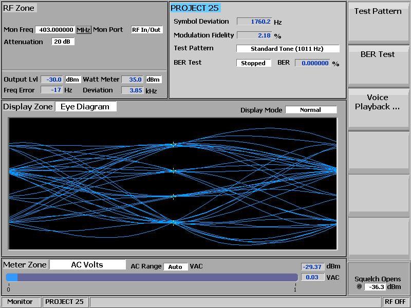
10 Digital P25 Transmitter Tests Press the blue Monitor hard key. Press the blue Test hard key. Select Test Mode. Select PROJECT 25. The Zones are now displaying the P25 Digital test parameters. Select RF Zone shortcut key 1. Select Monitor Frequency and using the numeric keypad enter the frequency of the channel to be tested, for example: MHz. Select Attenuation and set to 40dB using the Up/Down () keys or Spin Knob. Select Mon Port and set to RF In/Out. Select Input Level Units and set to Watts to display broadband power. Turn on the radio and set to the digital channel. Key the radio s PTT Note that the Symbol Deviation Hz and Modulation Fidelity% fields are displaying the quality of the radio s Digital Modulator. The Eye Diagram display is displaying the deviation of the carrier at the symbol decision times as measured though the post-detection filter. The tighter the four trajectories are to the + indicators the better the modulator performance. To observe the digital modulation on the Spectrum Analyzer, press hotkey 7 followed by Select Display and Spectrum Analyzer Adjust the Spectrum Analyzers Reference Level for the best dynamic range to view the input signal. Page 10 of 24

11 Page 11 of 24
12 Note 1: The R8000 configuration and settings above may be saved as a Preset. This avoids having to go through the setup procedure every time you need to conduct this test. Preset Save Procedure Press the blue Test hard key. Select Save Configuration As. Using the Alpha Numeric keypad, Left/Right () keys and Spin Knob enter a file name that will identify this test to you at a later date. Example, P25 DIG TX. Press the Enter key. This configuration will have populated into the list of available Presets. Voice Loop Back The R8000 does not employ a vocoder or encryption device. To allow these functions to be tested General Dynamics has patented the voice loop back function (U.S. patent ). Operation The patented voice loopback function requires the test operator to talk into the microphone of the radio. The analog voice is then digitized, coded and encrypted (if fitted) by the radios circuits and transmitted as a P25 frame. This frame is captured by the R8000 processing and applied to the digital modulator for retransmission to the radios receiver. This signal is demodulated, decoded and decrypted (if fitted) by the radios circuits and the resulting audio can be heard on the radios speaker. Set Up In PROJECT 25 TX test mode select the Monitor hard key then select Audio Zone using shortcut key 2. Select Voice Playback. From the voice playback menu select the Voice Playback key, followed by On Adjust Squelch control so that the blue recording bar is just triggered and returns to zero.. Select Duration and set the duration to the desired length of recoding, 1 to 10 seconds. Press Escape to go back to the main TX test screen. Press the radio s PTT and record your audio message Release the PTT, the R8000 will automatically go into the Generate mode and send the recorded message back to the radio. Page 12 of 24
13 Listen for your message on the radio s speaker; don t forget to turn up the volume! The R8000 automatically returns to the TX test Monitor mode after the message is complete To replay your messages at any time press the Voice Playback key and Play Last Recording from the menu. Press Esc to return to the Monitor screen. Page 13 of 24

14 Page 14 of 24
15 Bit Error Rate (BER) Tests TX BER Test TX BER tests require a PC running the Motorola Tuner software and that the radio be connected to the serial port of the computer through the programming and control cable supplied with the radio. With the power off, connect the radio to the PC s serial port using the supplied control cable. On the PC Start the Tuner software, then turn the radio power on. Press the Read icon on the software control panel. The radio will go into test mode and download its information to the PC. Under Performance Testing select Transmitter Test Pattern. In the Tx Frequency (MHz) display field enter the channel frequency to be tested. Select Standard TX Test Pattern (formerly CCITT V.52) in the Test Pattern field. On the R8000 in the Monitor mode select numeric key 2 to enter the Project 25 TX test menu. Select Test Pattern and set to Standard Tx (O.153/V.52). Press BER Test followed by Start On the Motorola Tuner control panel press PTT Toggle On the R8000 observe and ensure that the BER% display reads %. Page 15 of 24

16 Page 16 of 24
17 Digital Receiver Tests Press the blue Generate hard key. Press the blue Test hard key. Select Test Mode. Select PROJECT 25. Select numeric shortcut key 1 to enter the RF Zone. Select Generate Frequency and using the numeric keypad enter the frequency of the channel to be tested, for example: MHz. Select Output Level and using the numeric keypad or Spin Knob enter the desired RF output power. -100dBm is a good place to start. Select Gen Port and set RF In/Out using the Spin Knob. Select shortcut key 2 to enter the PROJECT 25 zone. Select Test Pattern and set to 1011 Hz Tone Select Modulation Mode and set to Continuous. Turn on the radio and set to the digital channel under test. You should now hear the 1011Hz digital test tone in the radio s speaker. Select shortcut key 1 to enter the RF Zone. Select Output Level. It is possible to get a very good approximation of the digital receiver s sensitivity by reducing the RF level using the Spin Knob until you hear the tone deteriorate or cut off. This normally occurs at around -121 to -122 dbm if you slowly approach the lower level in 1dB steps. This compares well with the -121dBm 12dB SINAD sensitivity achieved in Analog Mode. Page 17 of 24
18 Preset Save Procedure Press the blue Test hard key. Select Save Configuration As. Using the Alpha Numeric keypad, Left/Right () keys and Spin Knob enter a file name that will identify this test to you at a later date. Example, P25 DIG RX. Press the Enter key. This configuration will have populated into the list of available Presets. RX BER Sensitivity Test RX BER Sensitivity tests require a PC running the Motorola Tuner software and that the radio be connected to the serial port of the computer through the programming and control cable supplied with the radio. With the power off, connect the P25 radio to PC s serial port using the supplied control cable. On the PC Start the Tuner software, then turn the radio power on. Press the Read icon on the software control panel. The radio will go into test mode and download its information to the PC. Under RX select BER. In the Frequency display field enter the channel frequency to be tested. Select O.153 for the BER Test pattern Page 18 of 24
19 Select Yes for continuous operation. Connect the radio s antenna port to the R8000 RF In/Out port. In the RF zone on the R8000 set the output level to -116dBm; this is the Motorola specification to measure % BER. Select numeric key 2 followed by Test Pattern and set to Calibration (1011Hz 5%). Note: The calibration setting is provided to give a confidence level that the radio detects and reports a BER of 5%. This test pattern is set for 5 bit error in every 100 bits, i.e. 5%. Select Modulation Mode and set to On. On the Motorola Tuner screen scroll down and observe the BER test result; this should be 5.00%. On the R8000, select Test Pattern and set to O.153. On the Motorola Tuner screen, scroll down and observe the BER test result; this should be %. In the RF Zone adjust the RF level in 0.5dB decrements until the observed BER approaches 1%. This level is the absolute Digital RX sensitivity. Exit the tuner software, disconnect all test equipment and return the radio to normal operation. Page 19 of 24

20 Page 20 of 24

21 Project 25 Message Frame Encoding & Decoding. Version 1.9 Firmware for the R8000 and upwards Message Decode The Project 25 Message frame is updated dynamically for every valid received frame. The frame counter indicates the last frame decoded and the screen will freeze and display the last frame on release of the TX PTT key. To enable the decode display in the Display Zone in the Monitor Mode. 1. Select key 4 then Select Display 2. Select display Voice Frame Decode To enable the limited decode display in the Meter Zone 1. Select key*7* then Select Meter 2. Select meter Voice Frame Decode Page 21 of 24
22 Message Frame Encoder The R8000 P25 Message Frame Encoder allows the entry of data into all of the P25 standards variable fields. To enable the encode menu in the Generator Mode. 1. Select key 2 2. Select Voice Frame Encoder Page 22 of 24

23 Conclusion This application note has described the configurations and settings of both the R8000 and the P25 radio that enables you to make the required tests in Analog and Digital modes. In addition, for advanced users, the R8000 provides the functionality to decode and encode the standard P25 message frames. Page 23 of 24
24 Whilst this application note describes the Motorola P25 radio, any manufacturers P25 conventional radio may be tested using these procedures provided that the appropriate Tuner software and control cables are available. Page 24 of 24
Application Note: Testing P25 Conventional Radios Using the Freedom Communications System Analyzers
 : Testing P25 Conventional Radios Using the Freedom Communications System Analyzers FCT-1007A Motorola CPS and Tuner Software Motorola provides a CD containing software programming facilities for the radio
DMR Application Note Testing MOTOTRBO Radios On the R8000 Communications System Analyzer
 DMR Application Note Testing MOTOTRBO Radios On the R8000 Communications System Analyzer April 2 nd, 2015 MOTOTRBO Professional Digital Two-Way Radio System Motorola and MOTOTRBO is registered in the U.S.
Application Note: DMR Application Note Testing MOTOTRBO Radios On the Freedom Communications System Analyzer
 : DMR Application Note Testing MOTOTRBO Radios On the Freedom Communications System Analyzer MOTOTRBO Professional Digital Two-Way Radio System Motorola and MOTOTRBO is registered in the U.S. Patent and
Basic Transceiver tests with the 8800S
 The most important thing we build is trust ADVANCED ELECTRONIC SOLUTIONS AVIATION SERVICES COMMUNICATIONS AND CONNECTIVITY MISSION SYSTEMS Basic Transceiver tests with the 8800S Basic Interconnects Interconnect
Testing Motorola DMR MOTOTRBO Radios with the Cobham 3920B Radio Test Platform
 Application Note Testing Motorola DMR MOTOTRBO Radios with the Cobham 3920B Radio Test Platform The Cobham 3920B is the complete tool for anyone wishing to test Analog or Digital MOTOTRBO mobile or portable
PC Tune PC Tune Test Procedures for 5100 Series Portable Radios
 PC Tune PC Tune Test Procedures for 5100 Series Portable Radios Part Number 002-9998-6513014 August 2008 Copyright 2006, 2007, 2008 by EFJohnson Technologies The EFJohnson Technologies logo, PC Configure,
ID-5100 User Evaluation & Test Report
 ID-5100 User Evaluation & Test Report By Adam Farson VA7OJ/AB4OJ Iss. 1, August 13, 2014. Part I: Brief User Evaluation. Introduction: This report describes the evaluation and lab test of ID-5100 S/N 05001175.
Installed Radio Testing with the 3500
 Application Note Installed Radio Testing with the 3500 Aeroflex has uniquely designed the Aeroflex 3500 portable radio test set for complete testing of installed radio communication systems. The 3500 is
Agilent 8920A RF Communications Test Set Product Overview
 Agilent 8920A RF Communications Test Set Product Overview Cut through problems faster! The Agilent Technologies 8920A RF communications test set was designed to solve your radio testing and troubleshooting
FREEDOM Communications System Analyzer R8600 DATA SHEET
 FREEDOM Communications System Analyzer R8600 DATA SHEET Table of Contents Operating/Display Modes 3 General 3 Generator (Receiver Test) 4 Receiver (Transmitter Test) 5 Spectrum Analyzer 6 Oscilloscope
FREEDOM Communications System Analyzer R8000C DATA SHEET
 FREEDOM Communications System Analyzer R8000C DATA SHEET Table of Contents Operating/Display Modes General 3 3 Generator (Receiver Test) 4 Receiver (Transmitter Test) 5 Spectrum Analyzer 6 Oscilloscope
FREEDOM Communications System Analyzer R8100 DATA SHEET
 FREEDOM Communications System Analyzer R8100 DATA SHEET Table of Contents Operating/Display Modes 3 General 3 Generator (Receiver Test) 4 Receiver (Transmitter Test) 5 Spectrum Analyzer 6 Oscilloscope
FREEDOM Communications System Analyzer R8000C DATA SHEET
 FREEDOM Communications System Analyzer R8000C DATA SHEET Table of Contents Operating/Display Modes 3 General 3 Generator (Receiver Test) 4 Receiver (Transmitter Test) 5 Spectrum Analyzer 6 Oscilloscope
FREEDOM Communications System Analyzer R8100 DATA SHEET
 FREEDOM Communications System Analyzer R8100 DATA SHEET Table of Contents Operating/Display Modes General 3 3 Generator (Receiver Test) 4 Receiver (Transmitter Test) 5 Spectrum Analyzer 6 Oscilloscope
FREEDOM Communications System Analyzer R8100 DATA SHEET
 FREEDOM Communications System Analyzer R8100 DATA SHEET Table of Contents Operating/Display Modes 3 General 3 Generator (Receiver Test) 4 Receiver (Transmitter Test) 5 Spectrum Analyzer 6 Oscilloscope
R8000 SERIES COMMUNICATIONS SYSTEM ANALYZER OPERATOR S MANUAL
 R8000 SERIES COMMUNICATIONS SYSTEM ANALYZER OPERATOR S MANUAL General Dynamics SATCOM Technologies 3750 W. Loop 281 Longview Texas 75604 USA Tel: +1-903-295-1480 Fax: +1-903-295-1479 General Dynamics 2010
Tetra Base Station Test and Monitoring
 Tetra Base Station Test and Monitoring Introduction to Tetra Base Station Test and Monitoring The two options TETRA Base Station Monitoring ( R8-TETRA_BSM) and TETRA Base Station T1 Test (R8-TETRA_BST1)
Mastr III P25 Base Station Transmitter Tune-up Procedure
 Mastr III P25 Base Station Transmitter Tune-up Procedure 1. Overview The Mastr III Base Station transmitter alignment is performed in several steps. First, the Transmit Synthesizer module is aligned to
R8000 SERIES COMMUNICATIONS SYSTEM ANALYZER OPERATOR S MANUAL
 R8000 SERIES COMMUNICATIONS SYSTEM ANALYZER OPERATOR S MANUAL Documentation for firmware version 1.8.0.0 General Dynamics SATCOM Technologies 3750 W. Loop 281 Longview Texas 75604 USA Tel: +1-903-295-1480
Roger Kane Managing Director, Vicom Australia
 Understanding and testing of DMR standard Roger Kane Managing Director, Vicom Australia @CommsConnectAus#comms2014 Presentation Title: Understanding and Testing DMR Speaker: Roger Kane @CommsConnectAus
TECHNICAL INFORMATION BULLETIN
 TECHNICAL INFORMATION BULLETIN T/B No.: TIBFM 15-02 Rev A Revision date: JUNE24/08 Issue Date: JUNE18/08 TiL Model: TDFM-600/6000/7000 transceivers with Type I or Type II modules. TiL P/N: 011210-1,-2,-3,-4,-5
HP 8921A Cell Site Test Set. Product Note AMPS Base Station Testing
 HP 8921A Cell Site Test Set Product Note 8921-1 AMPS Base Station Testing AMPS Base Station Testing This product note describes manual operation of the HP 8921A Cell Site Test Set (or HP 8920A RF Communications
Technical Equipment Specification
 STATE OF CALIFORNIA Office of the State Chief Information Officer Public Safety Communications Division Technical Equipment Specification Equipment Type: Transmitter/Receiver Mobile Relay/Base/Control
VIAVI Solutions 8800 Series Software Release Notes
 Version 2.3.1 Release Notes 7/31/2018 1. A new field for temperature has been added to Option 13 Bird Thru Line Power meter. 1. The marker frequency entries are not altered by changing the center frequency
AUTOTUNE USER GUIDE. R8000 Series Communications Systems Analyzer. Motorola ASTRO XTL Series Motorola ASTRO XTS Series
 R8000 Series Communications Systems Analyzer AUTOTUNE USER GUIDE Motorola ASTRO XTL Series Motorola ASTRO XTS Series Freedom Communication Technologies 2002 Synergy Blvd, Suite 200 Kilgore, Texas 75662
JEM Radio II Operation Guide. Manual P/N M Victor Place Colorado Springs, Colorado
 JEM Radio II Manual P/N M09999-999 2115 Victor Place Colorado Springs, Colorado 80915 800.284.0399 www.jemcom.com Table of Contents Display... 3 Channel Entry... 4 Shortcuts... 4 Text Messages... 4 Buttons...
R8600 SERIES RADIO TEST HUB OPERATOR S MANUAL
 R8600 SERIES RADIO TEST HUB OPERATOR S MANUAL Documentation for firmware version 3.1.0.0 Freedom Communication Technologies 2002 Synergy Blvd. Suite 200 Kilgore Texas 75662 USA Tel/Fax: +1-844-903-7333
INDEX...2 INTRODUCTION...3 IMPORTANT NOTES...3 INSTALLING THE SOFTWARE...3 ST-965 PROGRAMMING SOFTWARE...6
 ST-965 VX/D SMARTRUNK II & SMARTRUNK XPRESS Logic board Programming Software 2.9e User s Guide Revision R2.9 10/10/2008 INDEX INDEX...2 INTRODUCTION...3 IMPORTANT NOTES...3 INSTALLING THE SOFTWARE...3
Measurement Procedure & Test Equipment Used
 Measurement Procedure & Test Equipment Used Except where otherwise stated, all measurements are made following the Electronic Industries Association (EIA) Minimum Standard for Portable/Personal Land Mobile
GM350 User Guide. GM350 User Guide. Safety Information. English
 GM350 User Guide GM350 User Guide Contents Page: Safety Information...1 General Information... 2 Radio Controls/Indicators... 2 Audio Signals... 3 Display Icons...3 Radio On/Off...3 Channel Selection...
ATB-7300 to NAV2000R Product Comparison
 ATB-7300 to NAV2000R Product Comparison Aeroflex Aeroflex Parameter / Function ATB-7300 NAV2000R Collins 479S-6A simulation Yes Yes ARINC 410 Auto-Tune Compatible No Yes Signal Generator Frequency Freq
TV SIGNAL LEVEL METER USER MANUAL
 TV SIGNAL LEVEL METER USER MANUAL - 0 - 1. Overview (1) (1) RF input (2) (3) A D E B C (2) Speaker (3) LCD display (4) Charger indicator (5) RS232 communication port (6) DC-IN port F G A. The battery icon
AUTOTUNE USER GUIDE. R8000 Series Communications System Analyzer. Motorola MOTOTRBO Portable Motorola MOTOTRBO Mobile
 R8000 Series Communications System Analyzer AUTOTUNE USER GUIDE Motorola MOTOTRBO Portable Motorola MOTOTRBO Mobile Freedom Communication Technologies 2002 Synergy Blvd, Suite 200 Kilgore, Texas 75662
3900 Series Digital Radio Test Set DMR Option Manual. Issue-10
 EXPORT CONTROL WARNING: This document contains controlled technical data under the jurisdiction of the Export Administration Regulations (EAR), 15 CFR 730-774. It cannot be transferred to any foreign third
200GTL ALIGNMENT REVISION: 1.0 BURKE MODEL: 200GTL REVISION: 1.2 DATE: 02/14/06. Total Pages: 6 pages. Page:1 print date: 9/23/09
 ALIGNMENT PROCEDURE MODEL: 200GTL REVISION: 1.2 DATE: 02/14/06 PREPARED BY: BURKE Total Pages: 6 pages Page:1 print date: 9/23/09 1 TEST CONDITION: 200GTL ALIGNMENT INSTRUCTION 1.0. TEST TEMPERTAURE: 77
Signal Generators for Anritsu RF and Microwave Handheld Instruments
 Measurement Guide Signal Generators for Anritsu RF and Microwave Handheld Instruments BTS Master Spectrum Master Tracking Generator Option 20 Vector signal Generator Option 23 Anritsu Company 490 Jarvis
S5101 Handheld Radio Communication Analyzer
 is the ideal radio tester for laboratory, production, service and maintenance use. It combines radio frequency emission, reception analysis, audio source, analyzer, etc. all into one unit. It can measure
8800SX DMR Repeater Test Option 06
 8800SX DMR Repeater Test Option 06 DMR Repeater Test Option The DMR Repeater test option allows testing of a DMR Repeater that is in conventional DMR Mode. Trunking or analog configurations are not supported.
AUTOTUNE USER GUIDE. R8000 Series Communications Systems Analyzer
 R8000 Series Communications Systems Analyzer AUTOTUNE USER GUIDE Portable Radios Motorola APX 2000 Motorola APX 4000 Motorola APX 6000 Motorola APX 7000 Mobile Radios Motorola APX 2500 Motorola APX 4500
Receiver Adjustments
 ! -8-4!5 This Section details procedures for tuning and adjustment of T2000 series II radios. This is normally only required during product manufacture or after major servicing. The following topics are
2801 Multilock. Communications System Analyzer. Data Sheet. Boosting wireless efficiency
 Data Sheet 2801 Multilock Communications System Analyzer Boosting wireless efficiency A real multi-talented instrument the Willtek 2801 Multilock The Willtek 2801 Multilock is a test instrument for multiple
Quick Site Testing with the 8800SX
 Quick Site Testing with the 8800SX Site Testing with the 8800SX Basic Tests 5 site testing involves several tests to verify site operation. NOTE: This is not intended to be a complete commissioning procedure.
IC-400pro - RADIOAFICION.COM
 PROCEDURES IC-400pro - 5- PREPARATION When you adjust the contents on pages 5-5 and 5-6, SOFT- WARE, the optional CS-400PRO ADJ SOFTWARE (Rev..0 or later), *OPC- JIG CABLE (modified OPC- CLONING CABLE;
Screen shots vary slightly according to Windows version you have.
 http://www.w1hkj.com/fldigihelp/audio_adjust_page.html Screen shots vary slightly according to Windows version you have. Receive audio Setting the correct hardware, operating system, and fldigi received
User Manual. Specifications...3. Control and Operation Microphone...8. Installation...9. Installation of Main Unit...9
 Contents Specifications...3 Control and Operation...4-7 Microphone...8 Installation...9 Installation of Main Unit...9 Antenna Installation...9 Operational test...9 Frequency Bands Table...10 Frequency
TS-590SG HF/ 50MHz All-Mode TRANSCEIVER_
 New Product Release Information Oct 2014 TS-590SG HF/ 50MHz All-Mode TRANSCEIVER_ Kenwood introduces Updated to new G version new HF/50MHz All-Mode Transceiver Four years ago we launched our best-selling
B & D Enterprises 1P repeater controller pg 1 INTRODUCTION:
 B & D Enterprises 1P repeater controller pg 1 INTRODUCTION: The 1P is a basic repeater controller. The controller uses low power devices and stores all commands and system status in non-volatile EE prom.
Microphone audio, from the MFJ-1278B to your transmitter. Ground, audio and PTT common. Push-to-talk, to allow the MFJ-1278B to key your transmitter.
 Computer interfacing, covered in the previous chapter, is only half the interfacing task. The other half is connecting your MFJ-1278B to your radios. MFJ-1278B Radio Ports Interfacing the MFJ-1278B to
SPECS FEATURES SUPPLIED ACCESSORIES. HF All Band Transceiver
 718 HF All Band Transceiver RX 0.030-29.999999MHz* TX 1.800-1.999999 MHz** 3.500-3.999999 MHz** 7.000-7.300000 MHz 10.100-10.150000 MHz 14.000-14.350000 MHz 18.068-18.168000 MHz 21.000-21.450000 MHz 24.890-24.990000
Dragon. manual version 1.7
 Dragon manual version 1.7 Contents DRAGON TOP PANEL... 2 DRAGON STARTUP... 2 DRAGON STARTUP SCREEN... 2 DRAGON INFO SCREEN... 3 DRAGON MAIN SCREEN... 3 TURNING ON A TRANSMITTER... 4 CHANGING MAIN SCREEN
VIAVI Solutions 3550 Series Software Release Notes
 Version 2.3.1 Release Notes 7/31/2018 1. A new field for temperature has been added to Option 14 Bird Thru Line Power meter. 1. The marker frequency entries are not altered by changing the center frequency
A Covert Tracking System Using the DDF5931
 1.0 Introduction A Covert Tracking System Using the DDF5931 A Technical Application Note from Doppler Systems April 25, 2004 This application note describes a simple covert tracking system using the Doppler
DuraFon UHF Quick Ref. / FAQ Sheet
 DuraFon UHF Quick Ref. / FAQ Sheet Technical support and RMA requests: support@engeniustech.com BASIC TROUBLESHOOTING If you encounter any issues with the system, first try power cycling both the handset(s)
DJ-MD5 PC Software Guidance
 DJ-MD5 PC Software Guidance Ver, 1.00 2018/08/16 1 Appendix I Public... 4 1. Channel... 4 1 Frequency, call type, power... 4 2 Digital Channel Setting... 5 3 Analog Channel Setting... 6 2. Zone... 7 3.
APX Mobile and Portable Automated Test and Alignment
 APX Mobile and Portable Automated Test and Alignment Software Updates First things first! Be sure to check that you are running the latest software versions for the 8800SX and its applications. Visit the
FCC ID: AXI IC: 10239A Alignment
 Introduction The VX-261 is carefully aligned at the factory for the specified performance across the frequency range specified for each version. Realignment should therefore not be necessary except in
VX-4100/4200SERIES. VHF/UHF Mobile Radios
 VX-4100/4200SERIES VHF/UHF Mobile Radios HIGH POWER OUTPUT (50W VHF/45W UHF) WIDE FREQUENCY SPAN 134-174 MHz (VX-4104/4204) 400-470 MHz / 450-520 MHz (VX-4107/4207) 501 CHANNELS/32 GROUPS (VX-4200 SERIES)
TC-3000C Bluetooth Tester
 TC-3000C Bluetooth Tester Product Instructions TC-3000C Bluetooth Tester is able to analyze the data of every packet that is transmitted to the upper application protocol layer using the protocol stack,
TY96 and TY97 VHF Radio Operating Manual
 TY96 and TY97 VHF Radio Operating Manual 01239-00-AA 18 February 2016 Trig Avionics Limited Heriot Watt Research Park Riccarton, Edinburgh EH14 4AP Scotland, UK Copyright 2016 EN Trig Avionics Limited
OBJECTIVES EQUIPMENT LIST
 1 Reception of Amplitude Modulated Signals AM Demodulation OBJECTIVES The purpose of this experiment is to show how the amplitude-modulated signals are demodulated to obtain the original signal. Also,
Modulation Analyzer FMAB
 Data sheet Version 02.00 Modulation Analyzer FMAB The specialist for sound broadcast signals from 50 khz to 1360 MHz December 2003 Built-in precision stereo decoder both for internal FM stereo decoding
DPT-1 & DPT-2. Dial Access Paging Terminal. Manual Revision: Covers Firmware Revisions: DPT: 1.57 and higher
 DPT-1 & DPT-2 Dial Access Paging Terminal Manual Revision: 2008-07-22 Covers Firmware Revisions: DPT: 1.57 and higher Covers Hardware Revisions: DPT-1: E and higher DPT-2: F and higher 1 TABLE OF CONTENTS
RMV25 / RMV50 RMU25 / RMU45
 RMV25 / RMV50 RMU25 / RMU45 Owner's Manual TABLE OF CONTENTS INTRODUCTION... 3 FCC Requirements... 3 SAFETY WARNING INFORMATION... 3 CONTROLS and INDICATORS... 5 FRONT PANEL... 5 LCD Icons and Indicators...
MOTOTRBO Professional Digital Two-Way Radio System DM 3400/3401/3600/3601 Mobile Radios
 MOTOTRBO Professional Digital Two-Way Radio System DM 3400/3401/3600/3601 Mobile Radios CLARITY PRODUCTIVITY VERSATILITY VALUE Shift into digital. Introducing MOTOTRBO Professional Digital Two-Way Radio
HR MHZ AM-FM AMATEUR RADIO HF TRANSCEIVER OWNER'S MANUAL. Content of the packaging
 HR-2800 28 MHZ AM-FM AMATEUR RADIO HF TRANSCEIVER OWNER'S MANUAL NOTICE! It is recommended to carefully read this owner s manual before using the product. This will also help to prevent illegal use of
SR3400 Base Station Module Configuration and Use Series-2 Cards Only
 SR3400 Base Station Module Configuration and Use Series-2 Cards Only A.W. Communication Systems Ltd Crook Barn, The Crook Rowel Town, Carlisle Cumbria Telephone (44) 1697-748777 Fax (44) 1697-748778 www.toneremote.com
Successful mobile-radio tester now with US TDMA and AMPS standards
 Universal Radio Communication Tester CMU200 Successful mobile-radio tester now with US TDMA and AMPS standards Digital TDMA standard TDMA (time-division multiple access) is a mobile-radio system based
FT-897 Alignment. Local Oscillator Adjustment. PLL Adjustment
 FT-897 Local Oscillator Adjustment Reference Frequency Adjustment a. Connect a frequency counter to TP1032. b. Adjust the trimmer capacitor (TC5001) for 67.875000MHz ±5Hz on the frequency counter. c. Connect
OPERATOR S MANUAL KYODO WEST MODEL KG506 FULL-DUPLEX MOBILE. Preliminary
 OPERATOR S MANUAL KYODO WEST MODEL KG506 FULL-DUPLEX MOBILE Preliminary 1.0 INTRODUCTION Thank you for purchasing the KYODO WEST MODEL KG506 Full-Duplex Mobile Radio. This manual contains information to
The equipment will provide up to 50W RF output power in the MHz band.
 19 September 2007 FAA Spectrum Engineering Division 800 Independence Avenue SW Washington, DC 20591 Dear Mr. Frazier, Please be advised that we shall be making an application to the Federal Communications
NXDN Signal and Interference Contour Requirements An Empirical Study
 NXDN Signal and Interference Contour Requirements An Empirical Study Icom America Engineering December 2007 Contents Introduction Results Analysis Appendix A. Test Equipment Appendix B. Test Methodology
AT-D868UV CodePlug Programming Guide
 INTRODUCTION The AnyTone D868UV radio is a VHF and UHF radio with both Digital DMR (Tier I and II) and Analog capabilities. It offers a total of 4,000 channels (Analog and Digital), 10,000 Digital Talk
Public Safety Radio Bands. VHF Low Band: 25 MHz to 50 MHz VHF High: 138 MHz to 174 MHz UHF: 408 MHz to 512 MHz 700 MHz (new) 800 MHz 4.
 800 MHz 4.") Public Safety Radio Bands VHF Low Band: 25 MHz to 50 MHz VHF High: 138 MHz to 174 MHz UHF: 408 MHz to 512 MHz 700 MHz (new) 800 MHz 4.9 GHz (new) Why is this a problem? Radios only operate in one band!
Public Safety Radio Bands VHF Low Band: 25 MHz to 50 MHz VHF High: 138 MHz to 174 MHz UHF: 408 MHz to 512 MHz 700 MHz (new) 800 MHz 4.9 GHz (new) Why is this a problem? Radios only operate in one band!
VX-2100/VX-2200 (UHF) Alignment
 Alignment") VX-2100/VX-2200 (UHF) Introduction The VX-2100/2200 is carefully aligned at the factory for the specified performance across the frequency range specified for each version. Realignment should therefore
VX-2100/VX-2200 (UHF) Introduction The VX-2100/2200 is carefully aligned at the factory for the specified performance across the frequency range specified for each version. Realignment should therefore
MODEL FVP-44. Setup & Programming Manual
 MODEL FVP-44 Rolling Code Encryption board for VX-450 / VX-4500 / VX-4600 VERTEX/STANDARD RADIOS Setup & Programming Manual Installation: Running the installation program, CimarronQuikWareSetupFVP44.EXE,
TurboVUi Solo. User Guide. For Version 6 Software Document # S Please check the accompanying CD for a newer version of this document
 TurboVUi Solo For Version 6 Software Document # S2-61432-604 Please check the accompanying CD for a newer version of this document Remote Virtual User Interface For MOTOTRBO Professional Digital 2-Way
Chapter-15. Communication systems -1 mark Questions
 Chapter-15 Communication systems -1 mark Questions 1) What are the three main units of a Communication System? 2) What is meant by Bandwidth of transmission? 3) What is a transducer? Give an example. 4)
MX800 BASE STATION SPECIFICATIONS
 MX800 BASE STATION SPECIFICATIONS Minimum performance to exceed the following for 30MHz to 960MHz*: Conforms but not all bands approved. GENERAL Frequency Range: AS4295-1995, R&TTE EC Directive 1995/05/EC,
 Options and their applications Extensions for basic model OCXO Reference Oscillator For long-term stability OCXO Reference Oscillator For extremely high long-term stability Duplex Modulation Meter Allows
WTI-100 Simplex wireless Interface Instruction Manual
 TELIKOU Intercom System WTI-100 Simplex wireless Interface Instruction Manual 2006 TELIKOU Systems All Rights Reserved www.telikou.com While TELIKOU makes every attempt to maintain the accuracy of the
3521 B 6 Vehicle Set VHF FM VEHICLE RADIO. VEHICLE SETS
 www.radmor.com RADMOR S.A. Hutnicza 3 81-212 Gdynia, Poland Foreign Customers Department: tel. +4858 69 96 621, fax: +4858 69 96 622 e-mail: export@radmor.com.pl VHF FM VEHICLE RADIO 3521 B 6 Vehicle Set
MIDLAND PROGRAMING G14
 MIDLAND PROGRAMING G14 1. PROGRAMMING CAPABILITY Welcome to the MIDLAND Programming software! It s a programming software specifically designed for G14 and must be used in conjunction with the dedicated
i2820h (USA) ie2820(europe)
 ie2820(europe)") January 2007 DUAL BAND TRANSCEIVERS i2820h (USA) ie2820(europe) The above photo shows the IC-2820H. The IC-E2820 differs slightly from this photo. Icom proudly announces the debut of the new dual band
January 2007 DUAL BAND TRANSCEIVERS i2820h (USA) ie2820(europe) The above photo shows the IC-2820H. The IC-E2820 differs slightly from this photo. Icom proudly announces the debut of the new dual band
TC-2300B DAB/DMB Tester
 TC-2300B DAB/DMB Tester Product Information TC-2300B DAB/DMB Tester supports the Eureka-147 (ESTI EN 301 500) system, freely changes every parameter related to protocols in a GUI operating system and simultaneously
Icom IC-9100 HF/VHF/UHF transceiver
 263 Walsall Road, Great Wyrley, Walsall, WS6 6DL Established 1997. Open Monday - Friday 9am - 5pm and Saturday 9.30am - 4pm Tel: 01922 414 796 Fax: 01922 417829 Skype: radioworld_uk Icom IC-9100 HF/VHF/UHF
INDEX...2 INTRODUCTION...3 IMPORTANT NOTES...3 INSTALLING THE SOFTWARE...3 ST-965 PROGRAMMING SOFTWARE...6
 ST-965 KW/D SMARTRUNK II & SMARTRUNK XPRESS Logic board Programming Software 2.9e User s Guide Revision R2.9.8 12/30/2008 INDEX INDEX...2 INTRODUCTION...3 IMPORTANT NOTES...3 INSTALLING THE SOFTWARE...3
BridgeCom Systems D Centimeter DMR and Analog Handheld Transceiver
 Product TechnicalReview Mark by Mark J. Wilson, Spencer, K1RO, WA8SME k1ro@arrl.org BridgeCom Systems D-500 70-Centimeter DMR and Analog Handheld Transceiver This solid radio offers an easy entry point
ECE 2111 Signals and Systems Spring 2009, UMD Experiment 3: The Spectrum Analyzer
 ECE 2111 Signals and Systems Spring 2009, UMD Experiment 3: The Spectrum Analyzer Objective: Student will gain an understanding of the basic controls and measurement techniques of the Rohde & Schwarz Handheld
WIRES-X Portable Digital Node Function. Instruction Manual
 Wide-Coverage Internet Repeater Enhancement System WIRES-X Portable Digital Node Function Instruction Manual Please read this Instruction Manual carefully for appropriate procedure. Preparation Procedure
Reference for UV-5R Menus by Jim Unroe - KC9HI 2-April-2014
 Long Name / Description / / Notes / 0 SQL Carrier Squelch Mutes the speaker of the transceiver in the absence of a strong signal. VHF squelch is either OFF or ON. UHF squelch is either OFF or one of 9
Midland 248XL I NSTRUCTION GUI DE
 Midland 248XL I NSTRUCTION GUI DE INDEX Introduction...2 Function and location of the controls...3 Installation...7 Power supply...7 Installing an antenna...7 How to use your Midland 248XL...8 Frequency
AT-D868UV CodePlug Programming Guide
 INTRODUCTION The AnyTone D868UV radio is a VHF and UHF radio with both Digital DMR (Tier I and II) and Analog capabilities. It offers a total of 4,000 channels (Analog and Digital) and up to 130,000 contacts,
Content. Maintenance. Features ENGLISH. 1 transceiver 1 antenna 1 battery pack 1 belt clip 1 fast desktop charger User manual
 ENGLISH Content 1 transceiver 1 antenna 1 battery pack 1 belt clip 1 fast desktop charger User manual If any items are missing, contact your dealer. Maintenance Your Two Way Radio is an electronic product
Yaesu FT-8800R Alignment
 DUAL BAND FM TRANSCEIVER Introduction and Precautions The FT-8800R has been carefully aligned at the factory for the specified performance across the 144 MHz and 430 MHz amateur bands. Realignment should
Appendix G: IFR 8800 Test Procedures MAINTENANCE GUIDE.
 Appendix G: IFR 8800 Test Procedures MAINTENANCE GUIDE www.codanradio.com MAINTENANCE GUIDE MT-4E ANALOG & P25 DIGITAL RADIO SYSTEMS Contents Appendix G: IFR 8800 Test Procedures...1 MT-4E Testing with
LNR Precision Mountain Topper MTR-4B and MTR-5B REV 2.0 User Manual for use with versions with 16 x 2 display.
 LNR Precision Mountain Topper MTR-4B and MTR-5B REV 2.0 User Manual for use with versions with 16 x 2 display. Four band MTR 4B shown Overview: The Mountain Topper Rigs are designed to be a very small,
WIRES-X Portable Digital Node Function. Instruction Manual
 Wide-Coverage Internet Repeater Enhancement System WIRES-X Portable Digital Node Function Instruction Manual Please read this Instruction Manual carefully for appropriate procedure. Preparation Procedure
TC-2300B DAB/DMB Tester
 www.tescom.co.kr DAB/DMB Tester Realtime Ensemble Mux (Unlimited Pattern Generation) OFDM Modulator RF Up-Converter Support Eureka-147(ETSI EN 301 400) protocol Combination test equipment (OFDM modulator
VHF Transceiver AR6201-(X0X) Software Versions: SCI1050S305 Version 3.05 SCI1051S305 Version 1.49 and upwards
 Software Versions: SCI1050S305 Version 3.05 SCI1051S305 Version 1.49 and upwards") VHF Transceiver AR6201-(X0X) Software Versions: SCI1050S305 Version 3.05 SCI1051S305 Version 1.49 and upwards Operating Instructions Issue 5 / November 2013 Article No. 0618.764-071 Becker Avionics GmbH
VHF Transceiver AR6201-(X0X) Software Versions: SCI1050S305 Version 3.05 SCI1051S305 Version 1.49 and upwards Operating Instructions Issue 5 / November 2013 Article No. 0618.764-071 Becker Avionics GmbH
What s in the pack? Getting Started - Initial Setup of Head Unit. Pairing a Remote
 V0.02 What s in the pack? Remote Key: 1 - Menu 6 - Station Right 2 - Add/Delete 7 - Preset Down 3 - Preset Up 8 - Scan 4 - Station Left 9 - On/Off 5 - OK Getting Started - Initial Setup of Head Unit On