To design Phase Shifter. To design bias circuit for the Phase Shifter. Realization and test of both circuits (Doppler Simulator) with
|
|
|
- Joan Nicholson
- 6 years ago
- Views:
Transcription
1 Prof. Dr. Eng. Klaus Solbach Department of High Frequency Techniques University of Duisburg-Essen, Germany Presented by Muhammad Ali Ashraf Muhammad Ali Ashraf
2 Outline 1. Motivation 2. Phase Shifters and their types 3. Varactor Diodes and Operational Amplifiers 4. Realization of Phase Shifter 5. Realization of Bias Circuit 6. Measurement Results 7. Brief Overview of Radars and their types 8. Phase Shifter with Doppler Radar 9. Conclusions 2
3 To design Phase Shifter. To design bias circuit for the Phase Shifter. Realization and test of both circuits (Doppler Simulator) with Doppler Radar. 3
4 Phase shifter is a two port device which by virtue of its design provides change in the phase of RF signal. The phase of a signal of wavelength λ passing through a line of length l at a velocity of v is as follows Parameters like frequency, length, permeability, permittivity, and velocity are considered in the design of any particular type of phase shifter. Depending on whether the phase shift is obtained by mechanical or electronic tuning, the phase shifter can be electronic or mechanical. 4
5 Based on the way of operation, they can be grouped as analog or digital. Another way of classifying the phase shifter is by considering the type of transmission media (e.g. waveguide, planar transmission line etc.) used in designing the phase shifter. The technology for fabrication (planar hybrid, or monolithic) is another way of classifying the phase shifter. 5
6 Varactor Diode is a semiconductor diode which is voltage dependent variable capacitor also known as varicap or voltacap, or voltage-variable capacitor diode. 6
7 It is a reverse-biased junction diode whose mode of operation depends on its junction capacitance. The size of depletion layer is in direct proportion to the applied reverse bias. Therefore, the capacitance of the varactor diode is changed with the changes in reverse bias. It may be of abrupt and hyper-abrupt types. If the doping concentration is constant in the active region then the varactor is abrupt varactor diode Otherwise it is hyperabrupt varactor diode. 7
8 Operational amplifiers can be considered as ideal amplifiers having following properties. Following is shown a differential amplifier. a. Very high input impedance b. Very low output impedance c. Very high gain 8
9 The non-inverting input appears on the output without any phase shift whereas as the other input appear on the output side with a phase difference of A large number of circuits can be employed by using the operational amplifier. E.g. amplifiers, integrators, comparators, oscillators, timers etc. 9
10 Diode phase shifter which employ varactors have been used for the realization of the Phase Shifter in this master thesis. Diode phase shifter posses following characteristics. a. They are almost immune to the normal temperature changes. b. Their switching is very rapid. c. They are very small sized. d. They can be used in microwave integrated circuit and can be used for the whole range of frequencies of interest of radar. e. They can be built using all types of transmission lines. f. Their loss increases and power handling decreases at higher microwave frequencies. 10
11 Phase Shifter Design here is based on loaded line topology. In loaded line topolgy, transmission line is periodically loaded with switched impedances. 11

12 The spacing between the diodes is ¼ wavelengths at the operating frequency Each pair produces just an increment of the whole phase shift required. Following figure shows the basic circuit used to design the phase shifter. 12
13 Length and width of microstripline along with the capacitance is tuned to get the desired phase shift with appropriate match. SMV LF varactor diodes have been used. Following are the PCB s layout, PCB of Phase shifter. 13
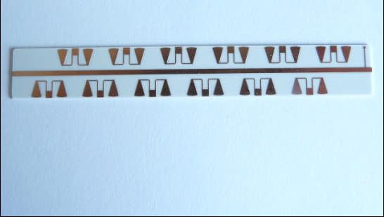
14 14

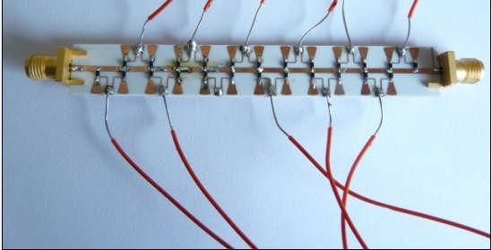
15 Phase Shifter 15
16 Schmitt trigger was preferred over comparator circuit in the realization of bias circuit. Comparator takes two inputs, compares them and produces the output of two states. This type of circuit has bistable output. The main problem of comparator circuit is that even small amount of noise will cause the output to switch back and forth. Following figures show the behaviour of comparator to noisy and nois free signals. 16
17 Response to noise free signal. 17
18 Response to noisy signal. 18
19 Solution to the above problem is Schmitt trigger. A feedback is introduced from the output to the non-inverting input. This feedback: a. Handles Noisy Signal (with two threshold levels). b. Results in fast output swing with slowly varying input. 19

20 Response of Schmitt Trigger to the noisy signal. UA741 OP AMP is used to realize schmitt trigger. In the following are diagram of schmitt trigger and image of bias circuit. 20

21 Schmitt Trigger for bias circuit 21

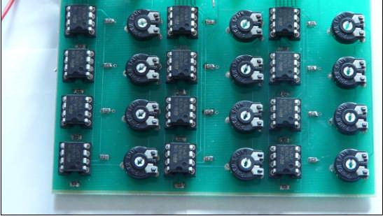
22 Bias Circuit 22
23 Performance of Phase Shifter together with the Bias Circuit y (dbs21) x (Steps) 23
24 Step by step increment in phase 200 y (Step by Step Increment in Phase of S2 21 (Degrees)) x (Steps) 24
25 Polar representation magnitude& radians 25
26 Table showing numerical values 26
27 Radar (or radio detection & ranging) is an electromagnetic system for the detecting and locating the reflecting objects such as aircraft, ships, space craft, vehicles and people. It operates by radiating energy into space and detecting the echo signal reflected from an object or target. Elementary components include transmitter, receiver and antenna. Continuous Wave Radar transmits energy in a continuous manner. A small proportion of energy is reflected by the target and returned to the receiver. Two types of Continuous Wave Radar include Continuous Doppler Radar and Frequency Modulated Continuous Wave Radar. 27
28 CW Doppler Radar sends continuous signal in the form of sine waves rather than pulses. It uses Doppler Effect to detect the frequency change caused by a moving target. Advantages & Disadvantages a. Accurate measurements of relative velocities while using low transmitting powers, simple circuitry, low power consumption and smaller equipment. b. Unaffected by the presence of stationary targets. c. Measure a large range of target speeds quickly and accurately. d. A limitation in the power that it can transmit which results in the limitation of its maximum range. e. It cannot specify the range of the target. f. It can easily get confused by the presence of a large number of targets. 28
29 Frequency Modulated Continuous Wave Radar can also determine the range. This can be accomplished if if the transmitted carrier is frequency modulated. The use of FM requires an increase in the bandwidth of the system, thus more information is conveyed. Phased Array Radar large number of radiators are used instead of only one radiator. This technology makes possible the radiation of the moving beam by a stationary antenna. 29
30 This beam steering can be achieved by the introduction of variable phase difference in the individual radiator s feeders. Pulsed Radar transmits pulses by a highly directional parabolic antenna at the target instead of continuous signal. Pulse repetition frequency (PRF) or pulse repetition rate (PRR) is controlled by a master timer. 30
31 Doppler Effect is the principle behind the working of Doppler radars. Doppler Effect is the change in the observed frequency of a source due to the relative motion between source and the receiver. Operation of Doppler radar is as follows: a. The signal is sent from the transmitter to the target. b. Reflection of the signal from the target in every direction occurs. c. From this reflected signal frequency is determined. d. If the frequency of the reflected signal appears to be increased, then the motion of the target is towards the receiver. e. Otherwise, if it is moving away from the receiver then the frequency of the reflected signal decreases. 31


32 Phase shifter setup with radar 32

33 Phase shifter setup with radar 33
34 The phase shifter produces more 360 degrees of phase shift. It has reasonably low value of -20 db for dbs 11 for both states. It can be used as an analog or discrete phase shifter. 34
35 Thanks for your Attention!!! 35
Doppler Simulator for 10 GHz Doppler Radar
 Doppler Simulator for 10 GHz Doppler Radar Presented by Ngeok Kuan Wai 2252462 Supervised by Prof. Dr.-Ing. K. Solbach Outline Motivation Doppler Radar and Doppler Simulator Phase shifter Other Electronic
R.B.V.R.R. WOMEN S COLLEGE (AUTONOMOUS) Narayanaguda, Hyderabad. ELECTRONIC PRINCIPLES AND APPLICATIONS
 Narayanaguda, Hyderabad. ELECTRONIC PRINCIPLES AND APPLICATIONS") R.B.V.R.R. WOMEN S COLLEGE (AUTONOMOUS) Narayanaguda, Hyderabad. DEPARTMENT OF PHYSICS QUESTION BANK FOR SEMESTER V PHYSICS PAPER VI (A) ELECTRONIC PRINCIPLES AND APPLICATIONS UNIT I: SEMICONDUCTOR DEVICES
R.B.V.R.R. WOMEN S COLLEGE (AUTONOMOUS) Narayanaguda, Hyderabad. DEPARTMENT OF PHYSICS QUESTION BANK FOR SEMESTER V PHYSICS PAPER VI (A) ELECTRONIC PRINCIPLES AND APPLICATIONS UNIT I: SEMICONDUCTOR DEVICES
Lecture Topics. Doppler CW Radar System, FM-CW Radar System, Moving Target Indication Radar System, and Pulsed Doppler Radar System
 Lecture Topics Doppler CW Radar System, FM-CW Radar System, Moving Target Indication Radar System, and Pulsed Doppler Radar System 1 Remember that: An EM wave is a function of both space and time e.g.
Understanding VCO Concepts
 Understanding VCO Concepts OSCILLATOR FUNDAMENTALS An oscillator circuit can be modeled as shown in Figure 1 as the combination of an amplifier with gain A (jω) and a feedback network β (jω), having frequency-dependent
LBI-30398N. MAINTENANCE MANUAL MHz PHASE LOCK LOOP EXCITER 19D423249G1 & G2 DESCRIPTION TABLE OF CONTENTS. Page. DESCRIPTION...
 MAINTENANCE MANUAL 138-174 MHz PHASE LOCK LOOP EXCITER 19D423249G1 & G2 LBI-30398N TABLE OF CONTENTS DESCRIPTION...Front Cover CIRCUIT ANALYSIS... 1 MODIFICATION INSTRUCTIONS... 4 PARTS LIST AND PRODUCTION
Experiment Topic : FM Modulator
 7-1 Experiment Topic : FM Modulator 7.1: Curriculum Objectives 1. To understand the characteristics of varactor diodes. 2. To understand the operation theory of voltage controlled oscillator (VCO). 3.
Chapter 16 Other Two-Terminal Devices
 Chapter 16 Other Two-Terminal Devices 1 Other Two-Terminal Terminal Devices Schottky diode Varactor diode Power diodes Tunnel diode Photodiode Photoconductive cells IR emitters Liquid crystal displays
INTRODUCTION. Basic operating principle Tracking radars Techniques of target detection Examples of monopulse radar systems
 Tracking Radar H.P INTRODUCTION Basic operating principle Tracking radars Techniques of target detection Examples of monopulse radar systems 2 RADAR FUNCTIONS NORMAL RADAR FUNCTIONS 1. Range (from pulse
ERICSSONZ LBI-30398P. MAINTENANCE MANUAL MHz PHASE LOCKED LOOP EXCITER 19D423249G1 & G2 DESCRIPTION TABLE OF CONTENTS
 MAINTENANCE MANUAL 138-174 MHz PHASE LOCKED LOOP EXCITER 19D423249G1 & G2 TABLE OF CONTENTS Page DESCRIPTION... Front Cover CIRCUIT ANALYSIS...1 MODIFICATION INSTRUCTIONS...4 PARTS LIST...5 PRODUCTION
Microwave Fundamentals A Survey of Microwave Systems and Devices p. 3 The Relationship of Microwaves to Other Electronic Equipment p.
 Microwave Fundamentals A Survey of Microwave Systems and Devices p. 3 The Relationship of Microwaves to Other Electronic Equipment p. 3 Microwave Systems p. 5 The Microwave Spectrum p. 6 Why Microwave
Radar level measurement - The users guide
 Radar level measurement The user's guide Radar level measurement - The users guide Peter Devine written by Peter Devine additional information Karl Grießbaum type setting and layout Liz Moakes final drawings
Optical Delay Line Application Note
 1 Optical Delay Line Application Note 1.1 General Optical delay lines system (ODL), incorporates a high performance lasers such as DFBs, optical modulators for high operation frequencies, photodiodes,
Chapter 6. FM Circuits
 Chapter 6 FM Circuits Topics Covered 6-1: Frequency Modulators 6-2: Frequency Demodulators Objectives You should be able to: Explain the operation of an FM modulators and demodulators. Compare and contrast;
1- Light Emitting Diode (LED)
") Content: - Special Purpose two terminal Devices: Light-Emitting Diodes, Varactor (Varicap)Diodes, Tunnel Diodes, Liquid-Crystal Displays. 1- Light Emitting Diode (LED) Light Emitting Diode is a photo electronic
Content: - Special Purpose two terminal Devices: Light-Emitting Diodes, Varactor (Varicap)Diodes, Tunnel Diodes, Liquid-Crystal Displays. 1- Light Emitting Diode (LED) Light Emitting Diode is a photo electronic
UNIT-I CIRCUIT CONFIGURATION FOR LINEAR
 UNIT-I CIRCUIT CONFIGURATION FOR LINEAR ICs 2 marks questions 1.Mention the advantages of integrated circuits. *Miniaturisation and hence increased equipment density. *Cost reduction due to batch processing.
Lecture 1 INTRODUCTION. Dr. Aamer Iqbal Bhatti. Radar Signal Processing 1. Dr. Aamer Iqbal Bhatti
 Lecture 1 INTRODUCTION 1 Radar Introduction. A brief history. Simplified Radar Block Diagram. Two basic Radar Types. Radar Wave Modulation. 2 RADAR The term radar is an acronym for the phrase RAdio Detection
Driver Amplifier for 7 Tesla MRI Smart Power Amplifier
 Driver Amplifier for 7 Tesla MRI Smart Power Amplifier presented by Kevin Kolpatzeck supervised by Prof. Dr.-Ing. Klaus Solbach Institute of Microwave and RF Technology University of Duisburg Essen Contents
Microelectronic Circuits
 SECOND EDITION ISHBWHBI \ ' -' Microelectronic Circuits Adel S. Sedra University of Toronto Kenneth С Smith University of Toronto HOLT, RINEHART AND WINSTON HOLT, RINEHART AND WINSTON, INC. New York Chicago
ETEK TECHNOLOGY CO., LTD.
 Trainer Model: ETEK DCS-6000-07 FSK Modulator ETEK TECHNOLOGY CO., LTD. E-mail: etek21@ms59.hinet.net mlher@etek21.com.tw http: // www.etek21.com.tw Digital Communication Systems (ETEK DCS-6000) 13-1:
Q.P. Code : [ TURN OVER]
![Q.P. Code : [ TURN OVER]](/thumbs/90/103239233.jpg "Q.P. Code : [ TURN OVER]") Q.P. Code : 587801 8ADF85B2CAF8DDC703193679392A86308ADF85B2CAF8DDC703193679392A86308ADF85B2CAF8DDC703193679392A86308ADF85B2CAF8DDC703193679392A86308ADF85B2CAF8DDC70 6308ADF85B2CAF8DDC703193679392A86308ADF85B2CAF8DDC703193679392A86308ADF85B2CAF8DDC703193679392A86308ADF85B2CAF8DDC703193679392A86308ADF85B2CAF8DDC703
Q.P. Code : 587801 8ADF85B2CAF8DDC703193679392A86308ADF85B2CAF8DDC703193679392A86308ADF85B2CAF8DDC703193679392A86308ADF85B2CAF8DDC703193679392A86308ADF85B2CAF8DDC70 6308ADF85B2CAF8DDC703193679392A86308ADF85B2CAF8DDC703193679392A86308ADF85B2CAF8DDC703193679392A86308ADF85B2CAF8DDC703193679392A86308ADF85B2CAF8DDC703
Design And Implementation Of Low Cost Microwave Motion. Sensor Based Security System
 Design And Implementation Of Low Cost Microwave Motion Sensor Based Security System M. S. S. Bhavani 1, Dr. K. Babulu 2 1 (Department of Electronics and Communication Engineering, JNTU Kakinada) 2 (Head
International Journal of Advance Research in Engineering, Science & Technology
 Impact Factor (SJIF): 4.542 International Journal of Advance Research in Engineering, Science & Technology e-issn: 2393-9877, p-issn: 2394-2444 Volume 4, Issue 4, April-2017 Design and Development of Varactor
Development of a noval Switched Beam Antenna for Communications
 Master Thesis Presentation Development of a noval Switched Beam Antenna for Communications By Ashraf Abuelhaija Supervised by Prof. Dr.-Ing. Klaus Solbach Institute of Microwave and RF Technology Department
Chlorophyll a/b-chlorophyll a sensor for the Biophysical Oceanographic Sensor Array
 Intern Project Report Chlorophyll a/b-chlorophyll a sensor for the Biophysical Oceanographic Sensor Array Mary Ma Mentor: Zbigniew Kolber August 21 st, 2003 Introduction Photosynthetic organisms found
ECEN689: Special Topics in Optical Interconnects Circuits and Systems Spring 2016
 ECEN689: Special Topics in Optical Interconnects Circuits and Systems Spring 2016 Lecture 9: Mach-Zehnder Modulator Transmitters Sam Palermo Analog & Mixed-Signal Center Texas A&M University Mach-Zehnder
RF Integrated Circuits
 Introduction and Motivation RF Integrated Circuits The recent explosion in the radio frequency (RF) and wireless market has caught the semiconductor industry by surprise. The increasing demand for affordable
Massachusetts Institute of Technology MIT
 Massachusetts Institute of Technology MIT Real Time Wireless Electrocardiogram (ECG) Monitoring System Introductory Analog Electronics Laboratory Guilherme K. Kolotelo, Rogers G. Reichert Cambridge, MA
Schottky diode mixer for 5.8 GHz radar sensor
 AN_1808_PL32_1809_130625 Schottky diode mixer for 5.8 GHz radar sensor About this document Scope and purpose This application note shows a single balanced mixer for 5.8 GHz Doppler radar applications with
CMOS Schmitt Trigger A Uniquely Versatile Design Component
 CMOS Schmitt Trigger A Uniquely Versatile Design Component INTRODUCTION The Schmitt trigger has found many applications in numerous circuits, both analog and digital. The versatility of a TTL Schmitt is
Basic Radar Definitions Introduction p. 1 Basic relations p. 1 The radar equation p. 4 Transmitter power p. 9 Other forms of radar equation p.
 Basic Radar Definitions Basic relations p. 1 The radar equation p. 4 Transmitter power p. 9 Other forms of radar equation p. 11 Decibel representation of the radar equation p. 13 Radar frequencies p. 15
RF AND MICROWAVE ENGINEERING
 RF AND MICROWAVE ENGINEERING FUNDAMENTALS OF WIRELESS COMMUNICATIONS Frank Gustrau Dortmund University of Applied Sciences and Arts, Germany WILEY A John Wiley & Sons, Ltd., Publication Preface List of
1. Explain how Doppler direction is identified with FMCW radar. Fig Block diagram of FM-CW radar. f b (up) = f r - f d. f b (down) = f r + f d
 = f r - f d. f b (down) = f r + f d") 1. Explain how Doppler direction is identified with FMCW radar. A block diagram illustrating the principle of the FM-CW radar is shown in Fig. 4.1.1 A portion of the transmitter signal acts as the reference
1. Explain how Doppler direction is identified with FMCW radar. A block diagram illustrating the principle of the FM-CW radar is shown in Fig. 4.1.1 A portion of the transmitter signal acts as the reference
Difference between BJTs and FETs. Junction Field Effect Transistors (JFET)
") Difference between BJTs and FETs Transistors can be categorized according to their structure, and two of the more commonly known transistor structures, are the BJT and FET. The comparison between BJTs
Difference between BJTs and FETs Transistors can be categorized according to their structure, and two of the more commonly known transistor structures, are the BJT and FET. The comparison between BJTs
100W High Power Silicon PIN Diode SPDT Switches By Rick Puente, Skyworks Solutions, Inc.
 October 2013 100W High Power Silicon PIN Diode SPDT Switches By Rick Puente, Skyworks Solutions, Inc. Radio transceiver designers have searched for a low cost solution to replace expensive mechanical switches
DEPARTMENT OF ELECTRONICS
 DEPARTMENT OF ELECTRONICS Academic Planner for odd Semesters Semester : I Subject : Electronics(ELT1). Course: B.Sc. (PME) Introduction to Number systems B Construction and types, working Review of P type
Fig 1: The symbol for a comparator
 INTRODUCTION A comparator is a device that compares two voltages or currents and switches its output to indicate which is larger. They are commonly used in devices such as They are commonly used in devices
Set No.1. Code No: R
 Set No.1 IV B.Tech. I Semester Regular Examinations, November -2008 RADAR SYSTEMS ( Common to Electronics & Communication Engineering and Electronics & Telematics) Time: 3 hours Max Marks: 80 Answer any
High Voltage Operational Amplifiers in SOI Technology
 High Voltage Operational Amplifiers in SOI Technology Kishore Penmetsa, Kenneth V. Noren, Herbert L. Hess and Kevin M. Buck Department of Electrical Engineering, University of Idaho Abstract This paper
Fundamentals Of Commercial Doppler Systems
 Fundamentals Of Commercial Doppler Systems Speed, Motion and Distance Measurements I. Introduction MDT manufactures a large variety of microwave oscillators, transceivers, and other components for the
Radio Frequency Electronics
 Radio Frequency Electronics Active Components I Harry Nyquist Born in 1889 in Sweden Received B.S. and M.S. from U. North Dakota Received Ph.D. from Yale Worked and Bell Laboratories for all of his career
P-N Diodes & Applications
 P-N Diodes & Applications Outline Major junction diode applications are Electronics circuit control Rectifying (forward mode) Special break-down diodes: Zener and avalanche Switching Circuit tuning (varactor)
COMMUNICATION SYSTEMS
 COMMUNICATION SYSTEMS 1. A cordless telephone using separate frequencies for transmission in base and portable units is known as A. duplex arrangement B. half duplex arrangement C. either (a) or (b) D.
Unit III FET and its Applications. 2 Marks Questions and Answers
 Unit III FET and its Applications 2 Marks Questions and Answers 1. Why do you call FET as field effect transistor? The name field effect is derived from the fact that the current is controlled by an electric
List of Figures. Sr. no.
 List of Figures Sr. no. Topic No. Topic 1 1.3.1 Angle Modulation Graphs 11 2 2.1 Resistor 13 3 3.1 Block Diagram of The FM Transmitter 15 4 4.2 Basic Diagram of FM Transmitter 17 5 4.3 Circuit Diagram
Operational Amplifiers
 Operational Amplifiers Table of contents 1. Design 1.1. The Differential Amplifier 1.2. Level Shifter 1.3. Power Amplifier 2. Characteristics 3. The Opamp without NFB 4. Linear Amplifiers 4.1. The Non-Inverting
Semiconductor Detector Systems
 Semiconductor Detector Systems Helmuth Spieler Physics Division, Lawrence Berkeley National Laboratory OXFORD UNIVERSITY PRESS ix CONTENTS 1 Detector systems overview 1 1.1 Sensor 2 1.2 Preamplifier 3
SRM INSTITUTE OF SCIENCE AND TECHNOLOGY (DEEMED UNIVERSITY)
") SRM INSTITUTE OF SCIENCE AND TECHNOLOGY (DEEMED UNIVERSITY) QUESTION BANK I YEAR B.Tech (II Semester) ELECTRONIC DEVICES (COMMON FOR EC102, EE104, IC108, BM106) UNIT-I PART-A 1. What are intrinsic and
SRM INSTITUTE OF SCIENCE AND TECHNOLOGY (DEEMED UNIVERSITY) QUESTION BANK I YEAR B.Tech (II Semester) ELECTRONIC DEVICES (COMMON FOR EC102, EE104, IC108, BM106) UNIT-I PART-A 1. What are intrinsic and
DHANALAKSHMI COLLEGE OF ENGINEERING DEPARTMENT OF ELECTRICAL AND ELECTRONICS ENGINEERING EC6202 ELECTRONIC DEVICES AND CIRCUITS
 DHANALAKSHMI COLLEGE OF ENGINEERING DEPARTMENT OF ELECTRICAL AND ELECTRONICS ENGINEERING EC6202 ELECTRONIC DEVICES AND CIRCUITS UNIT-I - PN DIODEAND ITSAPPLICATIONS 1. What is depletion region in PN junction?
Chapter 5. Operational Amplifiers and Source Followers. 5.1 Operational Amplifier
 Chapter 5 Operational Amplifiers and Source Followers 5.1 Operational Amplifier In single ended operation the output is measured with respect to a fixed potential, usually ground, whereas in double-ended
PRINCIPLES OF RADAR. By Members of the Staff of the Radar School Massachusetts Institute of Technology. Third Edition by J.
 PRINCIPLES OF RADAR By Members of the Staff of the Radar School Massachusetts Institute of Technology Third Edition by J. Francis Reintjes ASSISTANT PBOFESSOR OF COMMUNICATIONS MASSACHUSETTS INSTITUTE
(Refer Slide Time: 00:03:22)
") Analog ICs Prof. K. Radhakrishna Rao Department of Electrical Engineering Indian Institute of Technology, Madras Lecture - 27 Phase Locked Loop (Continued) Digital to Analog Converters So we were discussing
Analog ICs Prof. K. Radhakrishna Rao Department of Electrical Engineering Indian Institute of Technology, Madras Lecture - 27 Phase Locked Loop (Continued) Digital to Analog Converters So we were discussing
Figure 12-1 (p. 578) Block diagram of a sinusoidal oscillator using an amplifier with a frequencydependent
 Block diagram of a sinusoidal oscillator using an amplifier with a frequencydependent") Figure 12-1 (p. 578) Block diagram of a sinusoidal oscillator using an amplifier with a frequencydependent feedback path. Figure 12-2 (p. 579) General circuit for a transistor oscillator. The transistor
Figure 12-1 (p. 578) Block diagram of a sinusoidal oscillator using an amplifier with a frequencydependent feedback path. Figure 12-2 (p. 579) General circuit for a transistor oscillator. The transistor
50 W High Power Silicon PIN Diode SPDT Switch By Rick Puente, Skyworks Solutions, Inc.
 February 2012 50 W High Power Silicon PIN Diode SPDT Switch By Rick Puente, Skyworks Solutions, Inc. Radio transceiver designers have searched for a low cost solution to replace expensive mechanical switches
MSAN-001 X-Band Microwave Motion Sensor Module Application Note
 1. Introduction HB Series of microwave motion sensor modules are X-Band Mono-static DRO Doppler transceiver front-end module. These modules are designed for movement detection. They can be used in intruder
print close Related Low-Cost UWB Source Low-Cost Mixers Build On LTCC Reliability LTCC Launches Miniature, Wideband, Low-Cost Mixers
 print close Design A Simple, Low-Cost UWB Source Microwaves and RF Yeap Yean Wei Fri, 2006-12-15 (All day) Using an inexpensive commercial step recovery diode (SRD) and a handful of passive circuit elements,
EE301 Electronics I , Fall
 EE301 Electronics I 2018-2019, Fall 1. Introduction to Microelectronics (1 Week/3 Hrs.) Introduction, Historical Background, Basic Consepts 2. Rewiev of Semiconductors (1 Week/3 Hrs.) Semiconductor materials
Radar observables: Target range Target angles (azimuth & elevation) Target size (radar cross section) Target speed (Doppler) Target features (imaging)
 Target size (radar cross section) Target speed (Doppler) Target features (imaging)") Fundamentals of Radar Prof. N.V.S.N. Sarma Outline 1. Definition and Principles of radar 2. Radar Frequencies 3. Radar Types and Applications 4. Radar Operation 5. Radar modes What What is is Radar? Radar?
Fundamentals of Radar Prof. N.V.S.N. Sarma Outline 1. Definition and Principles of radar 2. Radar Frequencies 3. Radar Types and Applications 4. Radar Operation 5. Radar modes What What is is Radar? Radar?
4/30/2012. General Class Element 3 Course Presentation. Practical Circuits. Practical Circuits. Subelement G7. 2 Exam Questions, 2 Groups
 General Class Element 3 Course Presentation ti ELEMENT 3 SUB ELEMENTS General Licensing Class Subelement G7 2 Exam Questions, 2 Groups G1 Commission s Rules G2 Operating Procedures G3 Radio Wave Propagation
Analytical Chemistry II
 Analytical Chemistry II L3: Signal processing (selected slides) Semiconductor devices Apart from resistors and capacitors, electronic circuits often contain nonlinear devices: transistors and diodes. The
Continuous Wave Radar
 Continuous Wave Radar CW radar sets transmit a high-frequency signal continuously. The echo signal is received and processed permanently. One has to resolve two problems with this principle: Figure 1:
UNIT 8 : MTI AND PULSE DOPPLAR RADAR LECTURE 1
 UNIT 8 : MTI AND PULSE DOPPLAR RADAR LECTURE 1 The ability of a radar receiver to detect a weak echo signal is limited by the noise energy that occupies the same portion of the frequency spectrum as does
PA FAN PLATE ASSEMBLY 188D6127G1 SYMBOL PART NO. DESCRIPTION. 4 SBS /10 Spring nut. 5 19A702339P510 Screw, thread forming, flat head.
 MAINTENANCE MANUAL 851-870 MHz, 110 WATT POWER AMPLIFIER 19D902797G5 TABLE OF CONTENTS Page DESCRIPTION.............................................. Front Page SPECIFICATIONS.................................................
CMOS Schmitt Trigger A Uniquely Versatile Design Component
 CMOS Schmitt Trigger A Uniquely Versatile Design Component INTRODUCTION The Schmitt trigger has found many applications in numerous circuits both analog and digital The versatility of a TTL Schmitt is
Let us consider the following block diagram of a feedback amplifier with input voltage feedback fraction,, be positive i.e. in phase.
 P a g e 2 Contents 1) Oscillators 3 Sinusoidal Oscillators Phase Shift Oscillators 4 Wien Bridge Oscillators 4 Square Wave Generator 5 Triangular Wave Generator Using Square Wave Generator 6 Using Comparator
Five Ports Power Divider Designs with Controllable Power Division and Switching Capabilities
 Progress In Electromagnetics Research, Vol. 155, 93 103, 2016 Five Ports Power Divider Designs with Controllable Power Division and Switching Capabilities Ayman S. Al-Zayed *, Maryam J. Al-Yousef, and
(i) Determine the admittance parameters of the network of Fig 1 (f) and draw its - equivalent circuit.
 Determine the admittance parameters of the network of Fig 1 (f) and draw its - equivalent circuit.") I.E.S-(Conv.)-1995 ELECTRONICS AND TELECOMMUNICATION ENGINEERING PAPER - I Some useful data: Electron charge: 1.6 10 19 Coulomb Free space permeability: 4 10 7 H/m Free space permittivity: 8.85 pf/m Velocity
I.E.S-(Conv.)-1995 ELECTRONICS AND TELECOMMUNICATION ENGINEERING PAPER - I Some useful data: Electron charge: 1.6 10 19 Coulomb Free space permeability: 4 10 7 H/m Free space permittivity: 8.85 pf/m Velocity
HOW DIODES WORK CONTENTS. Solder plated Part No. Lot No Cathode mark. Solder plated 0.
 www.joeknowselectronics.com Joe Knows, Inc. 1930 Village Center Circle #3-8830 Las Vegas, NV 89134 How Diodes Work Copyright 2013 Joe Knows Electronics HOW DIODES WORK Solder plated 0.4 1.6 There are several
Exercise 1-3. Radar Antennas EXERCISE OBJECTIVE DISCUSSION OUTLINE DISCUSSION OF FUNDAMENTALS. Antenna types
 Exercise 1-3 Radar Antennas EXERCISE OBJECTIVE When you have completed this exercise, you will be familiar with the role of the antenna in a radar system. You will also be familiar with the intrinsic characteristics
Wireless Energy for Battery-less Sensors
 Wireless Energy for Battery-less Sensors Hao Gao Mixed-Signal Microelectronics Outline System of Wireless Power Transfer (WPT) RF Wireless Power Transfer RF Wireless Power Transfer Ultra Low Power sions
OBJECTIVE TYPE QUESTIONS
 OBJECTIVE TYPE QUESTIONS Q.1 The breakdown mechanism in a lightly doped p-n junction under reverse biased condition is called (A) avalanche breakdown. (B) zener breakdown. (C) breakdown by tunnelling.
Optical Receivers Theory and Operation
 Optical Receivers Theory and Operation Photo Detectors Optical receivers convert optical signal (light) to electrical signal (current/voltage) Hence referred O/E Converter Photodetector is the fundamental
Glossary of VCO terms
 Glossary of VCO terms VOLTAGE CONTROLLED OSCILLATOR (VCO): This is an oscillator designed so the output frequency can be changed by applying a voltage to its control port or tuning port. FREQUENCY TUNING
For the mechanical system of figure shown above:
 I.E.S-(Conv.)-00 ELECTRONICS AND TELECOMMUNICATION ENGINEERING PAPER - I Time Allowed: Three Hours Maximum Marks : 0 Candidates should attempt any FIVE questions. Some useful data: Electron charge : 1.6
Interactive Tone Generator with Capacitive Touch. Corey Cleveland and Eric Ponce. Project Proposal
 Interactive Tone Generator with Capacitive Touch Corey Cleveland and Eric Ponce Project Proposal Overview Capacitance is defined as the ability for an object to store charge. All objects have this ability,
LM146/LM346 Programmable Quad Operational Amplifiers
 LM146/LM346 Programmable Quad Operational Amplifiers General Description The LM146 series of quad op amps consists of four independent, high gain, internally compensated, low power, programmable amplifiers.
Chipless RFID ph Sensor for Food Spoilage Monitoring
 Chipless RFID ph Sensor for Food Spoilage Monitoring Formal Written Progress Report Prepared by: Group 05 Christian Espino John Baldwin Marvin Bataller Supervisor: Dr. G. Bridges Date of Submittal January
FSK DEMODULATOR / TONE DECODER
 FSK DEMODULATOR / TONE DECODER GENERAL DESCRIPTION The is a monolithic phase-locked loop (PLL) system especially designed for data communications. It is particularly well suited for FSK modem applications,
The Discussion of this exercise covers the following points:
 Exercise 3-2 Frequency-Modulated CW Radar EXERCISE OBJECTIVE When you have completed this exercise, you will be familiar with FM ranging using frequency-modulated continuous-wave (FM-CW) radar. DISCUSSION
Special-Purpose Operational Amplifier Circuits
 Special-Purpose Operational Amplifier Circuits Instrumentation Amplifier An instrumentation amplifier (IA) is a differential voltagegain device that amplifies the difference between the voltages existing
CHAPTER 3. Instrumentation Amplifier (IA) Background. 3.1 Introduction. 3.2 Instrumentation Amplifier Architecture and Configurations
 Background. 3.1 Introduction. 3.2 Instrumentation Amplifier Architecture and Configurations") CHAPTER 3 Instrumentation Amplifier (IA) Background 3.1 Introduction The IAs are key circuits in many sensor readout systems where, there is a need to amplify small differential signals in the presence
CHAPTER 3 Instrumentation Amplifier (IA) Background 3.1 Introduction The IAs are key circuits in many sensor readout systems where, there is a need to amplify small differential signals in the presence
Parallel Port Relay Interface
 Parallel Port Relay Interface Below are three examples of controlling a relay from the PC's parallel printer port (LPT1 or LPT2). Figure A shows a solid state relay controlled by one of the parallel port
Question Paper Code: 21398
 Reg. No. : Question Paper Code: 21398 B.E./B.Tech. DEGREE EXAMINATION, MAY/JUNE 2013 Fourth Semester Electrical and Electronics Engineering EE2254 LINEAR INTEGRATED CIRCUITS AND APPLICATIONS (Regulation
Prepared by: Dr. Rishi Prakash, Dept of Electronics and Communication Engineering Page 1 of 5
 Microwave tunnel diode Some anomalous phenomena were observed in diode which do not follows the classical diode equation. This anomalous phenomena was explained by quantum tunnelling theory. The tunnelling
This article reports on
 Millimeter-Wave FMCW Radar Transceiver/Antenna for Automotive Applications A summary of the design and performance of a 77 GHz radar unit David D. Li, Sam C. Luo and Robert M. Knox Epsilon Lambda Electronics
Summer 2015 Examination
 Summer 2015 Examination Subject Code: 17445 Model Answer Important Instructions to examiners: 1) The answers should be examined by key words and not as word-to-word as given in the model answer scheme.
ECE 678 Radar Engineering Fall 2018
 ECE 678 Radar Engineering Fall 2018 Prof. Mark R. Bell Purdue University RAdio Detection And Ranging RADAR It has become so commonplace that the acronym RADAR has evolved into a common noun: radar. A
Electronic Devices and Circuits
 Electronic Devices and Circuits I.J. Nagrath Electronic Devices and Circuits I.J. NAGRATH Adjunct Professor Former Deputy Director Birla Institute of Technology & Science Pilani New Delhi-110001 2012 ELECTRONIC
PRACTICE. Amateur Radio Operator Certificate Examination. Advanced Qualification
 Innovation, Science and Economic Development Canada Innovation, Sciences et Développement économique Canada Amateur Radio Operator Certificate Examination Advanced Qualification 2018-06-30 To pass this
Investigation of Comparator Topologies and their Usage in a Technology Independent Flash-ADC Testbed
 Investigation of Comparator Topologies and their Usage in a Technology Independent Flash-ADC Testbed Cand.-Ing. Öner B. Ergin Prof. Dr.-Ing. Klaus Solbach Department of Microwave and RF-Technology University
Optical Infrared Communications
 10/22/2010 Optical Infrared Communications.doc 1/17 Optical Infrared Communications Once information has been glued onto a carrier signal the information is used to modulate the carrier signal in some
Gechstudentszone.wordpress.com
 8.1 Operational Amplifier (Op-Amp) UNIT 8: Operational Amplifier An operational amplifier ("op-amp") is a DC-coupled high-gain electronic voltage amplifier with a differential input and, usually, a single-ended
DMI COLLEGE OF ENGINEERING
 DMI COLLEGE OF ENGINEERING DEPARTMENT OF ELECTRONICS & COMMUNICATION ENGINEERING EC8453 - LINEAR INTEGRATED CIRCUITS Question Bank (II-ECE) UNIT I BASICS OF OPERATIONAL AMPLIFIERS PART A 1.Mention the
ECEN 4634/5634, MICROWAVE AND RF LABORATORY
 ECEN 4634/5634, MICROWAVE AND RF LABORATORY Final Exam December 18, 2017 7:30-10:00pm 150 minutes, closed book, 1 sheet allowed, no calculators (estimates need to be within 3dB) Part 1 (60%). Briefly answer
Modern radio techniques
 Modern radio techniques for probing the ionosphere Receiver, radar, advanced ionospheric sounder, and related techniques Cesidio Bianchi INGV - Roma Italy Ionospheric properties related to radio waves
ELECTRONICS ADVANCED SUPPLEMENTARY LEVEL
 ELECTRONICS ADVANCED SUPPLEMENTARY LEVEL AIMS The general aims of the subject are : 1. to foster an interest in and an enjoyment of electronics as a practical and intellectual discipline; 2. to develop
FIBER OPTICS. Prof. R.K. Shevgaonkar. Department of Electrical Engineering. Indian Institute of Technology, Bombay. Lecture: 20
 FIBER OPTICS Prof. R.K. Shevgaonkar Department of Electrical Engineering Indian Institute of Technology, Bombay Lecture: 20 Photo-Detectors and Detector Noise Fiber Optics, Prof. R.K. Shevgaonkar, Dept.
Electrically Reconfigurable Radial Waveguides and Their Potential Applications in Communications and Radars Systems
 Progress In Electromagnetics Research C, Vol. 75, 147 153, 2017 Electrically Reconfigurable Radial Waveguides and Their Potential Applications in Communications and Radars Systems Halim Boutayeb * Abstract
MICROWAVE MICROWAVE TRAINING BENCH COMPONENT SPECIFICATIONS:
 Microwave section consists of Basic Microwave Training Bench, Advance Microwave Training Bench and Microwave Communication Training System. Microwave Training System is used to study all the concepts of
"Natural" Antennas. Mr. Robert Marcus, PE, NCE Dr. Bruce C. Gabrielson, NCE. Security Engineering Services, Inc. PO Box 550 Chesapeake Beach, MD 20732
 Published and presented: AFCEA TEMPEST Training Course, Burke, VA, 1992 Introduction "Natural" Antennas Mr. Robert Marcus, PE, NCE Dr. Bruce C. Gabrielson, NCE Security Engineering Services, Inc. PO Box
B.E. SEMESTER III (ELECTRICAL) SUBJECT CODE: X30902 Subject Name: Analog & Digital Electronics
 SUBJECT CODE: X30902 Subject Name: Analog & Digital Electronics") B.E. SEMESTER III (ELECTRICAL) SUBJECT CODE: X30902 Subject Name: Analog & Digital Electronics Sr. No. Date TITLE To From Marks Sign 1 To verify the application of op-amp as an Inverting Amplifier 2 To
B.E. SEMESTER III (ELECTRICAL) SUBJECT CODE: X30902 Subject Name: Analog & Digital Electronics Sr. No. Date TITLE To From Marks Sign 1 To verify the application of op-amp as an Inverting Amplifier 2 To