Heathkit SB200 Mods/SB-200 Modifications INTRODUCTION
|
|
|
- Charlene Chase
- 6 years ago
- Views:
Transcription

1 Heathkit SB200 Mods/SB-200 Modifications INTRODUCTION At a Dutch rally I once saw an open Heathkit SB-200 HF linear amplifier. This model, first marketed around 1965, still features in many amateur stations. The open amplifier seemed suitable for modification to accommodate the Russian valves GU-43B, GS-35B or GI-7B to get more output. I recently bought a used one on-line at a reasonable price. That remains risky, so the first thing checked here were the transformer and the meters, which were found OK. The cabinet showed its age but there were no dents or deep scratches. Replacements for their parts can usually be found. The design called for the -120V supply in the amplifier to energise the amplifier antenna relay through a contact on the PTT relay present in the valve transmitters of the day. Modern SSB transceivers have no such relay. That problem will be addressed After a good cleaning and check-up all looked presentable again. The two 572B valves turned out to be as good as the pair I had from another amplifier.


2 The cabinet is a bit like a suitcase, with a lid opening upwards. The internal height is 155 mm, but unfortunately, in the compartment where the two valves are horizontally mounted, the height is only 105 mm, insufficient for GU-43B or GS-35B without a lot of mechanical work. GI-7Bs would fit but I doubt these would produce more output than the originals. I decided to make such changes, possibly with new components as were required to make the amplifier fully serviceable. You may find my many experiments interesting and some of the resulting modifications useful. CONTENTS This article consists of four chapters: Ch. 1 contains modifications, which I believe to be good additions to the original design. Ch. 2 investigates the inclusion of the 160 m band, which was successfully tried but has not been permanently installed to date. Ch. 3 describes my thorough redesign, which also includes the modifications described in ch. 1. The amplifier currently is in that state of modification. Ch. 4 contains general information. CHAPTER 1 ELECTROLYTIC CAPACITORS


3 The six electrolytic capacitors in the HT supply looked a bit the worse for wear. Experience has taught me that they can loose as much as half their

4 capacity with age. I replaced the original 125 µf/450 V units with a smaller, modern 220 µf/450 V model. These («fig) are so small that could be installed below the chassis. The space where the old elecrolytics had been would then be available, e.g. for another filament transformer or a bigger valve. If the Bakelite PCB were removed, the full cabinet height of 155 mm would then be available. The primary of the power transformer has two 120 V windings which are series-connected for our nominally 230 VAC mains. At an actual mains voltage of 226 VAC, the DC HT was 2150 V unloaded and 1900 V fully loaded. For best protection I like to use fuses. Note the 2 A fuse in the transformer secondary. There is 30 kω/10 W resistor across each of the six electrolytics. Between them, they dissipate approx. 26 W and had turned somewhat brown. They also noticeably contribute to the temperature rise in the cabinet. Because of the lower leakage current of the modern electrolytics each 30 kω/10 W resistor can be replaced by two 220 kω/1 W resistors in parallel. The series-connected rectifier diodes did not need replacing. This series chain is remarkable, as earlier practice would have a resistor and capacitor in parallel with each. With modern diode manufacturing processes this is superfluous. If you want to replace µf/400 V caps with minor modification of the PCB, see the next pictures.


5

6 Cut the track for two caps on an extra PCB and move the red/yellow wire. A RESISTOR AND FUSE IN THE ANODE CIRCUIT DANGER There are few, if any, fuse holders which let you change a fuse at the 2 kv level without opening the cabinet. Before working inside the cabinet, make sure the mains plug has been pulled and the electrolytic capacitors have been discharged; bleeder resistors may open up without you knowing it. Belt and braces please!


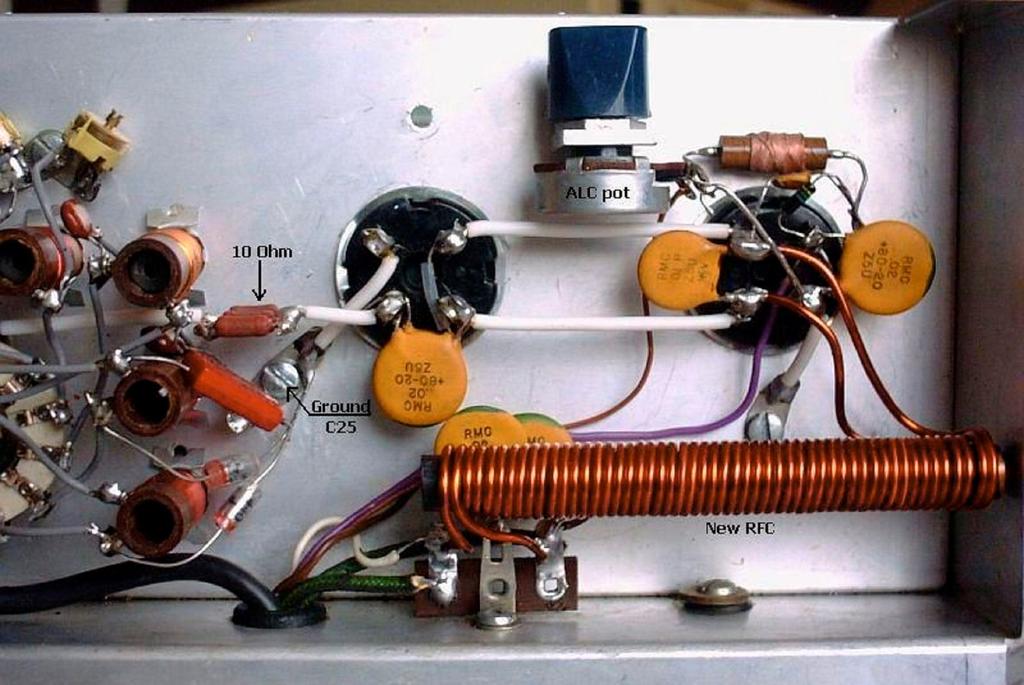
7 For first protection in all my power amps there is a fuse and a resistor in series with the anode feed. See diagram. That proved good practice in this amplifier. Within five minutes after first application of power, there was a flashover in one of the valves. The fuse had blown but the valve had not suffered. Under overdrive, the same thing happened. This time not only the fuse had blown but the 10 W resistor as well. Again, the valves were OK. Feel free to use a bigger resistor but I use these resistors as a second fuse and do not mind replacing them. When, after a few days, during which the amplifier had not been used, I powered up, this fuse blew again. It seems that this often occurs with this type of valve after they have not been used for a long time. Once the amplifier has stabilised and is in regular use, this only happens infrequently. An extra 4.7 nf/3 kv bypass capacitor from between the fuse and resistor provides additional filtering. A 4.7 nf/3 kv capacitor in parallel with the original 1 nf from the bottom of the anode choke to earth increases the output on 80 m. C12 (20 nf), originally across the filament choke, would be more effective if repositioned as shown in the diagram. GROUNDING C25 AND C26


8 The earth point of the tuning capacitor C25 is actually shielded by the back panel and RF currents have to make a detour to reach the grounded grids. A direct connection with heavy wire was therefore made from C25 to an earth point near the valve sockets. C26 was grounded at the front panel
 of the amplifier.")


9 with the band switch and that has been changed to a heavy wire to the frame of C25. All is shown by the outlines (red, yellow) in the pictures. This modification improves the stability (with less parasite oscillations) of the amplifier. METER PROTECTION A second modification is the protection of the meters against burnout resulting from stray RF or some fault condition. A capacitor and a pair of inverse-parallel diodes shunt each meter. A rectifier bridge may be used in lieu of discrete diodes. SOFT START A third important modification, which in my amplifier had been made by the previous owner, limits the primary inrush current due to the sudden charging of the electrolytic capacitors and slows the rise of the anode voltage. This protects the filaments and rectifier diodes and permits the use of a lowercurrent primary fuse. RF INPUT CONNECTOR This connector has been replaced by a BNC socket, which does fit the existing hole. Bayonet connectors facilitate experimentation and I use them wherever possible. MEASURING THE HIGH VOLTAGE After testing and finding the transformer OK, the amplifier was powered up without valves. With the meter switch in the HT position, there was no reading as two of the three

10 4.7 MΩ resistors had opened up because of old age or overloading. Replace them with resistors of better quality or by a chain of 1.5 MΩ or smaller resistors totalling 14.1 MΩ. It is good to know the HT fairly exactly. The reading can be calibrated against a precision voltmeter with HT probe if the circuit of fig a is used. A fixed resistor in parallel with the adjustment potentiometer limits the overload to the meter in case one of them fails. I used the circuit of fig b. (I happened to have a 4.7 MΩ HT resistor in the junkbox). PARASITE SUPPRESSORS


11 One of the resistor leads looked ready to break. I undid the coils and measured the resistors: nominally 47 Ω, they had increased to 82 Ω. I replaced the stoppers with the ones shown in the photographs, which I had previously found more effective than the original design. The 56 Ω/2 W composition resistors (I happened to have that value) are shunted by hairpin loops made of Teflon-insulated stranded wire, which is easy to bend but then holds its shape. The effective length of the white wire is 100 mm but cut off a 115 mm to allow for connection to the resistor leads. These dimensions had been optimised on an earlier amplifier and were found to be effective here too. GROUNDING THE GRIDS The grounding of the grids is unusual and needs some explanation. In fig a, the grid with its long lead to earth represents a self-inductance which cannot be ignored. It, effectively, isolates the grid from earth, which may give rise to spurious oscillation. In the 30L-1 amplifier Collins have solved this by inserting a 200 pf capacitor in this lead. It, together with this selfinductance, makes a series-resonant VHF circuit, which prevents this oscillation. A non-inductive resistor of 22 or 33 Ω across the capacitor broadband this circuit (fig b). Some designers do not know why this series

12 capacitor is only 200 pf and use a much higher capacity. Had Heathkit followed the Collins example, the circuit would look like fig c. In fact, they used circuit d, in which the 33 R resistor does not have the damping effect but does provide some DC inverse feedback, which tends to improve power sharing between two unmatched valves. Collins chose a 200 pf capacitor for older types of 572B valves and I doubt that would be optimum for more recent 572Bs. My SB-200 amplifier with Cetron 572Bs uses the circuit of fig e with nf per valve. The amplifier remains stable and its output, measured with a Bird 43 meter with 2.5 kw insert and a Bird 50 Ω dummy load, is as in the table below. Driving power Anode voltage with key down 80 m 100 W V 750 W This output is more than I expected. At the full mains voltage an output on 80, 40 and 20 m of almost 40 m 750 W 800 W can be expected. The plate 20 m 17 m (bandswitch on 15 m) 15 m 12 m (bandswitch on 10 m) 10 m 750 W 700 W 750 W 680 W 650 W off-load voltage then is 2100 V; on average voice SSB it is 2050 V and 2000 V during a series of CW dots. The SSB and CW output exceeds the datasheet values! Increasing the grid decoupling capacitors can have even more output but then the recommended plate current is exceeded. It also considerably changes the input impedance of the 572Bs and it becomes more difficult to adjust the input circuits for an acceptable SWR. The original 200 pf grid capacitors (fig») were a bit under dimensioned for the currents they must pass. During experimentation one of them shorted, affecting the 120 V bias supply. The remaining bias was then inadequate to fully suppress the plate current during reception. In my amplifier I have installed more rugged types, old-fashioned tubular ceramics rated at 1.5 nf/1 kv. Install them with the shortest possible leads as close to the valve socket as you can.


13 INPUT CIRCUITS After changing the grounding of the grids as described, the input circuits were tuned by adjustment of the coil cores and capacitors for best SWR in the centre of each band. Do not forget though that all depends on how the wiring is dressed. You may find different values for your amplifier, especially at the higher frequency bands. Using 100 pf ceramic trimmers makes things easier. They can handle the 100 W drive without problems. 10 m C38 = 33 pf SWR = m 10 m input circuit SWR = m 15 m C* = 56 pf 15 m input circuit C36 = 39 pf SWR = 1.3 SWR = 1.4 A good compromise is to be found for the 10, 12, m C33 = 360 pf C34 = 200 pf SWR = 1.0 and 17 m 40 m C31 = 510 pf C32 = pf SWR = 1.0 bands. If you adjust for a m C30 = pf SWR = 1.0 m SWR of 1.2, it will be 1.7 on 17 m and vice-versa. An average of 1.4 for both bands is a good compromise. If you want to operate above 28.5 MHz, the SWR will exceed 1.5. A separate circuit would be required to improve on that. If you can achieve an SWR of 1.0 on 10 or 12m, the output increases by 30 50W. Where an input circuit is only an L-network, the length of the coax from the driver and stray capacity may affect the SWR. INPUT CIRCUIT 10 m Having tried various circuits for 10 and 12 m, all of which did work, I still was not happy. With a properly dimensioned pi network, a 1.0 SWR should be possible. The self-inductance of L1 actually was too small and has been increased to approx. 620 nh. Replace the three turns with six turns of 1mm wire. If wound on a 9 mm drill bit, a tight fit


14 on the coil former results. Secure with a drop of super glue. Note that C1 has been replaced by one of 100 pf. Careful tuning now achieves an SWR < 1.2 on both bands, and 1.0 on either band. INPUT CIRCUIT 15 m On 10 and 15 m moving the cores in the coils does not have much effect. That is because the stray capacity of the layout and wiring is excessive. By replacing the L- network by a pi-network, pf on 15 m with a coil in between, the stray capacity becomes part of that circuit and the SWR is not so much affected by the coax length. C36 then must be 150 pf less the stray capacity. L2 should be about 750 nh, ten turns of 1 mm wire replacing the original five turns. If you also want to revamp the 20 m circuit, you can use the original 20 m coil on 15 m and rewind the original 15 m former for 20 m. By adjusting the core of L2 and C36, an SWR < 1.3 can be achieved on both 15 and 17 m. I found a good compromise with the original C36 = 76 pf. It is quite a job but I believe it to be well worthwhile if one input circuit has to serve on two bands. The easiest way is to tune for a 1.0 SWR in the centre of the 15 m band and then, on 17 m, to adjust C36 for an SWR < 1.5. INPUT CIRCUIT 20 m In my SB200, after transmitting on 20 m for a few minutes, the input coil got so hot that at one occasion the plastic trimming tool stuck to its core. I suspected that this resulted from too high a Q. That Q was then reduced by replacing C34 by a 100 pf capacitor and using the removed 200 pf to replace the 360 pf unit at C33. L3 then must be increased to approx. 1.2 µh, 13 turns. The heating of the 20 m coil now is less, but still worse than on the other bands. I do not know why this should be so. To give a good overview, here are the input circuits for all bands as I left


15 them: THE FILAMENT CHOKE The wire and core of the filament choke and the 10 Ω feed-back resistor got quite hot when working on 80 m. I suspected that the selfinductance of the choke was too small. That proved true it was only 10 µh. From my experiments with the input circuits and some calculations regarding the values of the tuning capacitors found, I concluded that the real part of the input impedance of the two valves together is Ω. A self-inductance of 10 µh at 3.5 MHz has a reactance of only 220 Ω, which shunts the 135 Ω input impedance of the valves. Even on 40 m is the choke a bit small. A considerable fraction of the drive power is absorbed by the choke. The 10 Ω-feedback resistor is no longer small in comparison to the total input impedance and also got hotter than it should. I replaced the choke by a homemade one of 20 µh, 2 26 turns of 1.8mm wire on an AM-radio antenna ferrite rod, 100 mm long and 9.5 mm diameter. The unwarranted heating no longer occurs. On my 226 VAC mains (it drops to 221 VAC under full load), the filament voltage measured at the valve pins is 6.14 V, good for long valve life. If 160 m operation is contemplated, an even larger filament choke, wound end-toend on a 125 mm or longer ferrite rod, would help. The new choke requires retuning of the input circuits for best SWR. The difference is greatest on 40 and 80 m. Note that C32 (310pF) of the 40 m circuit has been replaced with 240 pf and that C30 (470 pf) of the 80 m circuit must now be 440 pf. REDUCING THE DRIVE After all was re-assembled and properly tuned up, it turned out that 100 W of drive was a bit much for two Cetron 572Bs; W is sufficient to produce the recommended grid current. One way to accommodate a 100
16 W driver is the installation of a 10 Ω/10 W non-inductive feedback resistor. The valves then cannot be overdriven, the driver sees a less reactive load, and the inverse feedback contributes to good linearity. It sometimes also reduces the danger of parasitic oscillation. After the installation of this resistor and a touch-up of the input circuits the output was not lower than before. Compare the preceding table with the following readings: Driving power (with 10 Ω fitted) 100 W Anode voltage with key down 1950 V 80 m SWR = W Not a bad result for an old nag, is it? 40 m SWR = W Actually, on 12 m with 20 m SWR = W the 15 m output tank 17 m (bandswitch on 15 m) SWR = W selected, and 15 m SWR = W a proper in circuit m (bandswitch on 10 m) SWR = W 750 W output could 10 m SWR = W be had but with the 15/17 m input circuit the input SWR would be excessive on 12 m. Because of voltage doubling in the HT supply the plate voltage and output are very sensitive to the mains voltage of the moment. It can make a difference of as much as W, occasionally even 200 W in RF output if the mains voltage dips because of the load of the amplifier. GRID BYPASS CAPACITORS


17 With the 10 Ω feedback resistor in place, there was no longer a need to calm the valves by series-tuning the bypassing of the grids by means of small capacitors. Besides, the 1500 pf ceramics I had installed got fairly hot. That being suspicious, I replaced them with old-fashioned of mica 10 nf. Because the wiring between filaments is fairly long, I installed a 10 nf capacitor across the filament end of the choke where there originally had been a 20 nf capacitor, the latter having been moved to the input before. ANTENNA RELAY SWITCHING Though my Ten Tec Corsair II transceiver is capable of switching the relay from the V supply, most current transceivers are not. The diagram («fig) shows a fairly simple way of switching with low voltage and current. On first sight this seems a strange circuit. Three rectifier diodes and two electrolytic capacitors create 12 VDC from the 6.3 VAC filament supply (it will also be used for the extra 12 VDC fan mentioned in Ch. 4). To do that, the centre tap of the transformer filament winding must be cut from the chassis. The two lefthand diodes re-establish centre grounding for the tube filaments. Because these diodes pass the cathode current of both valves, they must be rated for 1A minimum but preferably 3 A. The +12 VDC is earthed. R16 must be disconnected from the output connector ANT RELAY and is connected to the additional reed relay. A new 4.7 kω resistor is then connected to ANT RELAY. With this modification, the transceiver needs to switch only a few ma from a negative supply. (T1 = 20 V/ 50 ma NPN). 160m MODIFICATION CHAPTER 2 SUITABLE 160 m MOD WITH PI OUTPUT CIRCUIT
 is not a receiving type with the narrow plate spacing, but it has wider spaced plates.")
18 It was the intention to make this SB200 amplifier suitable for 160 m, using a Pi-L anode circuit and a separate input filter. As you may have noted, the original SB200 loading capacitor (C28A+B) is not a receiving type with the narrow plate spacing, but it has wider spaced plates. This makes it possible to use this capacitor in a Pi-L filter. However, although the SB200 loading capacitor is suitable for a Pi-L filter on 160 m, the problem is that the combined self-induction of all the tank circuits is too small for a filter of this kind. It is possible to change this situation, but that would be quite involved and I decided not to take this route. Instead two Pi-filters for 160 m were made and tested (see Fig a and Fig b). The tank circuit in Fig a has a Q of approximately 5. This circuit has the advantage that only an extra fixed capacitor (1800 pf) is required in parallel with the existing SB220 loading capacitor, and uses the total capacity of the 80 m tuning capacitors (C25+C26). The Q of the tank circuit in Fig b is about 10 and it requires an extra 250 pf capacitor in parallel with the 80 m tuning capacitors (C25 + C26) to tune to 160 m. Switching the SB200 input circuit for 160 m requires only a small relay, but a heavier one is needed to open/short an extra coil (or switch in an extra capacitor) so that the SB200 tank circuit resonates on 160 m. To make the SB200 tank circuit resonant on 160 m, an inductor wound on a toroidal core is switched in series with the 80 m tank coil. Because the toroidal core has no external field, it can be conveniently mounted under the chassis, near the opening to the loading capacitor. To carry out this modification (see Fig a and Fig b) the only thing required is to break the connection from the existing SB200 loading capacitor (C28A/C28B) to the band-switch and insert the extra inductor (L) between

19 the contacts of a heavy duty relay (Rel1) at this point. Note that the circuit ideas described above are in a preliminary state and have not moved beyond testing at this stage. When one does a lot of experimenting, it is important to keep an open mind and not to forget or skip over things. For example, when I first looked at the original SB200 anode choke, I thought it was rather small for use on 160 m, and that I should measure it one day. Unfortunately, that day did not come until the one when I tried my modified SB200 on 160 m and found I could not to get more than 150 W RF output on 160 m, contrary to my previous experiences with these valves. I then spotted again the small anode choke (which only measured 50 µh) and remembered that too small an anode choke results in low RF output. When I hooked up a second anode choke in series with the original one, the SB200 output on 160 m went up to 500 W! This was not bad, considering that the line supply was ± 221 VAC and on 80 m only 600 W was produced. Moreover, I was actually using the 80 m input circuit on 160 m, with a tuner to get a 1 : 1 SWR on 160 m. I also noticed that the grid current on 160 m was less than on other bands and suspect that this results from the filament choke having too little inductance (10 µh) for 160 m. SIMPLER DESIGN FOR 160 m On the internet, there is some information on improving the SB200 which advises changing the LC input circuit for 80 m into a Pifilter. Although I also prefer the use of a Pi-filter for a linear amplifier input circuit, I determined that the 80 m LC input circuit in my SB-200 is working properly, with the input SWR at the band edges being 1.2 : 1. As the 160 m band is quite narrow, an LC circuit should be suitable for that as well. Following this route, modifying the SB200 input circuit for 160 m
 toroidal core, wound with 32 to 33 turns.")
20 can be simplified by using the 80 m inductor as part of the 160 m inductor (see fig» above). How this will work in reality still has to be tested. Note that the 13 µh inductor used in the tank circuit modified for 160 m can be made using an Amidon T200-2 (or larger) toroidal core, wound with 32 to 33 turns. CHAPTER 3 MORE COMPLEX MODS FOR ANT RELAY, GRIDS AND METER CIRCUIT As mentioned in the introduction, I got this amplifier to experiment without having to do too much mechanical work. Because I had previously modified another amp with 3 572B valves and using a directly grounded grid design, I finally changed this SB- 200 according to the schematic given here. The components have been numbered with their original numbers. As much as possible I have used the original components, the extra parts have not been numbered in the diagram. The modification is quite involved, as the ALC circuit as well as the anode and grid current meter circuit needs to be changed to fit in with this modification. Although the diagram looks quite complex, it can be build rather compact. With the new design any modern set can be used to drive the amp, as the switching only requires V at 200 µa. The HF grounding is much
 is switched to ground through 4 3 Amp diodes when both transistors earth the relay. This series of diodes creates the negative grid voltage of approx. 2.8 V.")
21 better using the grounded grids. The valves are switched off with a positive voltage through the coil of the tx/rx relay. The cathode (filament) is switched to ground through 4 3 Amp diodes when both transistors earth the relay. This series of diodes creates the negative grid voltage of approx. 2.8 V. The idle current can be changed by adding or removing some of these diodes. Please note that the polarity of the components of the 120 V secondary has been reversed compared to the original design. I did not have a 10 Ω/10 W resistor so I used in the input circuit five 47 Ω/1.2 W units (fig») in parallel. This works but is borderline, it is better to use a 10 W resistor. The mosfet K538 was discarded from a PC power supply and the NPN transistor can be any universal type, like a BC547. The 330 Ω resistor between R15 and the meter switch is used to scale the meter. 500 ma indicated on the meter relate to 100 ma grid current, 400 ma is then 80 ma, etc. In my SB-200 this 330 Ω resistor, in combination with R15, turned out to be on spot, otherwise a trim-potmeter can be used. On the left you can see an EURO socket for the line-power inlet, on the right the BNC connector for the input of the amplifier. The new ALC circuit delivers a voltage between 0 and 35V. A new and smaller capacitor has replaced C3. The over-voltage protection (SG) looks like a small neon-bulb and is made by Siemens. During testing everything went fine and this protection has never blown, but to be of the safe side I have permanently mounted it (bottom-left corner in the photo). All components have been mounted on the mounting tab, which has been moved from the valve bases to the bottom, close to the fan. The airflow keeps both transistors cool.


22


23 At the back, where the mounting tab used to be, I have made an angle bracket, which holds the ALC potmeter. As you can see (fig») this modification has created some more room. The unused pin of the right-hand valve base has been used to mount the other components of this circuit. INCREASED ANODE VOLTAGE Because a number of linear amplifiers available for the radio amateur are fitted with 572B s and are using 2700 VDC supplies. Therefore I increased the anode voltage using a 230 VAC/0.6 A transformer. As mentioned before this transformer can be mounted in the space previously occupied by the old electrolytic capacitors. A suitable unit I had lying around fits easily in this space. This second transformer is wired in series with the 800 VAC of the voltage doubling circuit. Using a switch one could choose normal or turbo output power. The higher anode voltage requires the capacitor-bank to be made out of µf/400 V units. A test of this higher anode voltage, using an external power supply, showed an extra 125 W in key-down and about 200 W PEP extra in SSB. While this is not too spectacular, the negative grid current reduced considerably and this means that the bias of the valves was improved. Measurements after adding the second transformer have shown at 2250 VDC (key-down and optimum supply line-voltage): 850 W output on 80,40,20,17,and 15 meters, 750 W on 10 m and 725 W on 12 m. Using SSB the average voltage was 2550 VDC. This means, using an efficiency of


24 62%, 950 W PEP output. Sending a rapid series of dots showed 2450 VDC. Using 50 W drive I got 600 to 650 W out of my turbo charged SB-200. Unloaded anode voltage was 2950 VDC. Input SWR did not vary much and both loading and tuning capacitors required only minimal adjustment. The output is more stable and doesn t depend as much on the supply line voltage as before using the higher anode voltage. It is best to not exceed 800 W carrier output. I don t know the specs of the original rectifying diodes, but they withstood the tests with the raised anode voltage. I have however replaced them


25 with 10 BY225 (1300 V/3 A). To get a neat and compact layout the whole modification did take longer than expected. The photo shows the mounting of the transformer and the placing of the 8 capacitors under the meter between the transformer and the frontpanel. The capacitors and their parallel resistors have been mounted on an epoxy print. This print is then mounted in such a way that 4 of the caps are above the chassis and 4 below. Another print with diodes and measuring resistors has been mounted on the chassis under the extra transformer. Checking and final tuning all input filters resulted in the following SWR values: INPUT SWR WITH UPGRADED ANODE SUPPLY Using 2 new valves and 221 VAC line input the output in key-down condition is W. CHAPTER 4 OPTIMIZING INPUT CIRCUITS


26 (10m) and C36(15m) are replaced with trimmer caps L to R: L1(10m) = 6t, L2(15m) = ex L3(20m) = 10 t, L3 = ex L2 = 13t If you want to add or optimise a input circuit it is best to use the C-values giving in the table. Starting with a fixed input value, experiment with Lx and Cx to get the lowest SWR. Replacing Cx with a piece of coax cable terminated with a variable capacitor (Ct) makes for and easy to reach adjustment. Be aware that the cable capacitance has to be added to the found optimum value of the trimmer at the end of the cable. This then becomes the value of the fixed capacitor, so Cx=Ct + Ccable. If you can t get a SWR of 1, change C a small amount and then carry on using Lx and Cx. Every change in the output filter in the anode circuit will influence the input SWR. Make sure the output is tuned for maximum output power into a suitable 50 Ohms dummy load. Take especially care on 10 m, a power difference of 50 W can make the input SWR more than 1.5! In this amplifier 10 and 12 m share a common input filter as well as 15 and 17 m. To get a good compromise on all four bands Cx has been made up out of 2 plastic trimmers («fig). EXTRA FAN

. After that I tried mounting it lying down next to the original fan, this worked fine except on 15 m, where it slowed down due to RFI interference.")

27 The original fan can be lubricated, and I recommend doing this frequently. I find the cooling it provides sufficient, even during tests using the raised anode voltage. I do make ample breaks to let things cool down. Although I don t use the amp a lot, or only for short periods, I have been trying to blow the air from underneath the valves with a small 12 V fan, mounted using double sided tape next to one of the valves (fig). After that I tried mounting it lying down next to the original fan, this worked fine except on 15 m, where it slowed down due to RFI interference. In the end I settled on a PC fan ( mm) mounted on 2 small brass lugs soldered to the motor of the original fan. Power is supplied («fig) through rectifying and doubling of the 6.3 VAC filaments supply. Please note that the positive and negative poles are floating. This is an easy way to mount the assisting fan without a lot of mechanical work and is quite adequate for normal use. If you plan on using this amp a lot and for long periods at a time, it may be better to place a bigger fan on top of the cabinet above the valves, to assist in getting more air through. That is the most effective and easiest way to achieve this. There are articles on the internet showing the original fan being replaced by a more powerful 120 VAC type in the same place, or a similar 12 V type. EXTRA SWITCHING WAVER

 I received a 572B with a loose base and failed vacuum. Filament Zero signal plate current Max signal plate current Max signal grid current Driving impedance 6.")
28 Switch waver: Harbach Electronics has replacement wafers for sale for about $30. These can be used to add 2 extra bands, such as 30 and 160 m, to this amplifier. This company also has various other interesting parts for the SB-200, such as a softstart module, a better fan, electrolytic capacitors, etc. VALVES 572B/T160L Plate max CETRON 572B/T160L 2400 V In the past years I have only bought CETRON second hand valves, they all have proven to be very satisfactory in my power amps. Only once («fig) I received a 572B with a loose base and failed vacuum. Filament Zero signal plate current Max signal plate current Max signal grid current Driving impedance 6.3 V/4 A 20 ma 250 ma 45 ma 215 Ω These (Chinese?) CETRON valves have a hard life during my extended experiments, and many tests, but they never fail. These are really rugged valves and extremely well suited for Resonant load impedance Max signal drive power Plate input 4500 Ω 30 W 600 W PEP homebuilt linear amplifiers. The table (fig») lists the specs of the valves, as far as I can tell these are applicable for ICAS applications.
 shows that the maximum drive for 2 valves is 60 W.")
29 Information provided by Waters Electronic Company for optimum amateur communication in ICAS for 2 572B in parallel: Grounded grid application Anode voltage Anode current Resting current Driving power HF output power 2150 V 600 ma 100 ma 120 W 800 W Amplifier terminated in 50 Ohms and adjusted for max output power The table («fig) shows that the maximum drive for 2 valves is 60 W. In practice there are all kinds of losses (way of construction, mounting, and components) and this 60 W can be not enough. 100 W from a driver will probably deliver 60 W effective to the valves, but whether you are overdriving them or not can only be really assessed using a scope. Other manufacturers specify a max drive of 60 W per valve. In a lot of amplifiers collapsing of the anode voltage at full drive prevents the maximum output power being achieved. The valves made by various manufacturers are not all of the same length (fig»), This can sometimes lead to problems when replacing a valve in a particular amp. All valves in the photo vary in length. The 2 left-hand units are made by CETRON, the middle one by RF-Parts and the 2 right-hand units are a UEW-57-B and a UE-572B by Waters Electronic Company. All these valves, as well as all my other 572B s deliver the same output when fitted in this amplifier (using a 10 Ohms feedback resistor). The inputs also remain unchanged. In my experience, not only with this but also with other amplifiers, it is not worthwhile to get 2 matched valves. WORN OUT VALVES?

30 Cetron & Svetlana, take notice of the smaller plate of the Svetlana's 572B! A reduction of the quiescent current can be an indication that the emission of one or both valves is reducing. At the same time the SWR between the driving transceiver and the amp will raise. Driving the amplifier key-down till one of the valves turns red indicates which one is degrading. The worst valve will not be so red as the good one. The Svetlana 572B was designed for AF applications and the plate is of smaller size than that of other makes, therefore I do not advise to use the Svetlana's.
Modifying The Heath HA-14 For 6 Meters Greg Chartrand - W7MY 4/22/07
 Introduction The Heathkit HA-14 was one of the few electron tube linear amplifiers intended for mobile use but few were purchased with the 12 volt mobile power supply. Most hams bought the HA-14 for base
A 100-Watt Transmitter Using a Pair of VT1625s
 12/16/2007 6:00 PM VT1625 100 Watt Transmitter A 100-Watt Transmitter Using a Pair of VT1625s FIG. 10.6 A 100-watt transmitter for five bands, using salvaged TV power transformer and surplus 1625 amplifier
A 75-Watt Transmitter for 3 Bands Simplified Shielding and Filtering for TVI BY DONALD H. MIX, W1TS ARRL Handbook 1953 and QST, October 1951
 A 75-Watt Transmitter for 3 Bands Simplified Shielding and Filtering for TVI BY DONALD H. MIX, W1TS ARRL Handbook 1953 and QST, October 1951 The transmitter shown in the photographs is a 3-stage 75-watt
Instruction Manual OM3500 HF SHORTWAVE POWER AMPLIFIER. OM POWER, s. r. o Bác 126 SLOVAKIA
 Instruction Manual OM3500 HF SHORTWAVE POWER AMPLIFIER OM POWER, s. r. o. 930 30 Bác 126 SLOVAKIA Important safety instructions: The amplifier contains high voltage circuits. Never turn the amplifier on
G6ALU 20W FET PA Construction Information
 G6ALU 20W FET PA Construction Information The requirement This amplifier was designed specifically to complement the Pic-A-Star transceiver developed by Peter Rhodes G3XJP. From the band pass filter an
MFJ-249B HF/VHF SWR ANALYZER
 TABLE OF CONTENTS MFJ-249B... 2 Introduction... 2 Powering The MFJ-249B... 3 Battery Installation... 3 Alkaline Batteries... 3 NiCd Batteries... 4 Power Saving Mode... 4 Operation Of The MFJ-249B...5 SWR
JC-5 4KW PEP, 1KW RMS AUTO ANTENNA COUPLER
 JC-5 4KW PEP, 1KW RMS AUTO ANTENNA COUPLER 1) DIRECTLY CONTROLLED BY ICOM, ALINCO & KENWOOD. 2) INDEPENDENT CAPACITOR INPUT AND OUTPUT BLOCKS! 3) 3 mm COIL WIRE & INTERNAL FAN FOR THE BIG COILS! 4) DIPPED
SWR myths and mysteries.
 SWR myths and mysteries. By Andrew Barron ZL3DW September 2012 This article will explain some of the often misunderstood facts about antenna SWR at HF and uncover some popular misconceptions. The questions
The 6LE8 One Tube Broadcaster
 The 6LE8 One Tube Broadcaster Introduction The purpose of this broadcaster is to transmit your favorite music to every AM radio in your home. The transmitting power is so low that it should not bother
C.M.HOWES COMMUNICATIONS CTU150 Instructions
 CTU150 Instructions The HOWES CTU150 is an antenna matching unit for use with shortwave transmitters and receivers. A novel constructional method is used - all parts being mounted on a Printed Circuit
Ameritron ALS-600 Retrofit ALS-600-LPF Assembly Manual
 Ameritron ALS-600 Retrofit ALS-600-LPF Assembly Manual FEATURES Automatic band change based on TX frequency. PIN diode QSK RX/TX switch. Temperature controlled FAN for quiet operation. RS-232 serial port
CX7 Troubleshooting Index
 CX7 Troubleshooting Index Modification S/1 Newsletter Guide Board Description A/TO A/TO MODE Intermod V1,12 P4.4 A11 Shut off one 35 MHz osc in receive, done sn 244 A/TO Spur V1,12 P1 Reduce A/TO spur,
BY ALLEN W. KING,* W1CJL QST May 1955 *Project Engineer, Harvey-Wells Electronics, Inc., Southbridge, Mass.
 BY ALLEN W. KING,* W1CJL QST May 1955 *Project Engineer, Harvey-Wells Electronics, Inc., Southbridge, Mass. This comes close to being the ultimate in multiband antenna couplers, from the standpoint of
CHALLENGER II HF LINEAR AMPLIFIER
 CHALLENGER II HF LINEAR AMPLIFIER (GS 35 Model) Operating Manual WiMo Antennen und Elektronik GmbH Am Gäxwald 14, D-76863 Herxheim Tel. (07276) 96680 FAX 6978 http://www.wimo.com e-mail: info@wimo.com
WiMo Antennen und Elektronik GmbH Am Gäxwald 14, D Herxheim Tel. (07276) FAX 6978
 FAX 6978") 2m DISCOVERY LINEAR AMPLIFIER (GS 31) Operating Manual WiMo Antennen und Elektronik GmbH Am Gäxwald 14, D-76863 Herxheim Tel. (07276) 96680 FAX 6978 http://www.wimo.com e-mail: info@wimo.com INDEX 1. Specifications
2m DISCOVERY LINEAR AMPLIFIER (GS 31) Operating Manual WiMo Antennen und Elektronik GmbH Am Gäxwald 14, D-76863 Herxheim Tel. (07276) 96680 FAX 6978 http://www.wimo.com e-mail: info@wimo.com INDEX 1. Specifications
A Transmatch for Balanced or Unbalanced Lines
 A Transmatch for Balanced or Unbalanced Lines Most modern transmitters are designed to operate into loads of approximately 50 Ω. Solid-state transmitters produce progressively lower output power as the
1 TRANSISTOR CIRCUITS
 FM TRANSMITTERS The first group of circuits we will discuss are FM TRANSMITTERS. They can be called SPY TRANSMITTERS, FM BUGS, or a number of other interesting names. They all do the same thing. They transmit
Dentron Clipperton L Conversion to GI-7B Tubes and Other Modifications. Pat Griffin AA4PG
 Dentron Clipperton L Conversion to GI-7B Tubes and Other Modifications Pat Griffin AA4PG Walking out of Dayton, 2014 my eye caught a beat up Clipperton cabinet under a vendor table. Twenty bucks and it
KWM-2/2A Transceiver THE COLLINS KWM-2/2A TRANSCEIVER
 KWM-2/2A Transceiver Click the photo to see a larger photo Click "Back" button on browser to return Courtesy of Norm - WA3KEY THE COLLINS KWM-2/2A TRANSCEIVER Unmatched for versatility, dependability and
LBI-4938C. Mobile Communications MASTR II POWER AMPLIFIER MODELS 4EF4A1,2,3. Printed in U.S.A. Maintenance Manual
 C Mobile Communications MASTR II POWER AMPLIFIER MODELS 4EF4A1,2,3 Printed in U.S.A. Maintenance Manual TABLE OF CONTENTS DESCRIPTION.................................................... 1 CIRCUIT ANALYSIS.................................................
Central Electronics Model 600L Linear Amplifier
 INTRODUCTION This manual has been reproduced by James Lawrence, NA5RC, a 600L owner. Text no longer applicable such as insurance claim with the carrier has been deleted. Some capitalization and grammar
HF Amateur SSB Receiver
 HF Amateur SSB Receiver PCB Set for radio club project http://rhelectronics.net PCB for DIY HF Amateur SSB Receiver 20M The receiver is a simple syperheterodyne type with quartz crystal filter. The circuit
HAMTRONICS TB901 FM EXCITER INSTALLATION, OPERATION, & MAINTENANCE
 HAMTRONICS TB901 FM EXCITER INSTALLATION, OPERATION, & MAINTENANCE GENERAL INFORMATION. The TB901 is a single-channel low power fm transmitter (exciter) designed to provide 300-600 milliwatts continuous
Hot Water for the K2. K1RFD Building the K2 More K2 Photos. Using an HW-101 as a 100-watt PA. Hot Water for the K2. EchoStation
 Page 1 of 5 K1RFD Building the K2 More K2 Photos EchoStation Using an HW-101 as a 100-watt PA When I was a young ham in 1977, I saved money to buy and build a Heathkit HW-101. The rig has served me well
A GOOD REGENERATIVE RECEIVER WITH SIMPLE FINE TUNING (2008)
") A GOOD REGENERATIVE RECEIVER WITH SIMPLE FINE TUNING (2008) A good SSB-CW-AM regenerative receiver with a fine tuning by moving the wooden stick with a grounded piece of PCB towards the coil. A good regenerative
A GOOD REGENERATIVE RECEIVER WITH SIMPLE FINE TUNING (2008) A good SSB-CW-AM regenerative receiver with a fine tuning by moving the wooden stick with a grounded piece of PCB towards the coil. A good regenerative
2-Tone Generator For 145Mhz
 Wolfgang Schneider, DJ8ES 2-Tone Generator For 145Mhz An RF amplifier stage is not only classified by amplification, which is as high as possible, and thus by its maximum output. What is frequently not
Hendricks QRP Kits The Twofer Rev
 Hendricks QRP Kits The Twofer Rev 1 11-15-06 1. Description The Twofer is a classic QRP transmitter that s easy to assemble and operate. It uses a JFET VXO (variable crystal oscillator), driver stage and
1 FUNCTIONAL DESCRIPTION WAY SPLITTER/INPUT BOARD FET RF AMPLIFIERS WAY POWER COMBINER VSWR CONTROL BOARD...
 CONTENTS 1 FUNCTIONAL DESCRIPTION...1 2 4-WAY SPLITTER/INPUT BOARD...2 3 FET RF AMPLIFIERS...3 4 4-WAY POWER COMBINER...4 5 VSWR CONTROL BOARD...5 6 ADJUSTMENT OF BIAS VOLTAGE TO ESTABLISH PROPER QUIESCENT
Instructions MODIFICATION KIT MODEL SBM - 1O2-1 INTRODUCTION PARTS LIST FOR THE
 Instructions FOR THE MODIFICATION KIT MODEL SBM - 1O2-1 INTRODUCTION This modification Kit applies to the following Heath Transceivers: 1. All Models HW-100, SB-100, SB-101 and SB-101W. 2. Any Model SB-102
CONSTRUCTION. Refer to schematic and component location diagrams during assembly
 HAMTRONICS VHF RECEIVING CONVERTERS CONSTRUCTION, ALIGNMENT, & INSTALLATION INSTRUCTIONS GENERAL DESCRIPTION. The CA( ) series of VHF Receiving Converter modules are designed to amplify and convert the
KN-Q10 Assembly Manual
 KN-Q10 Assembly Manual Translated by Adam Rong, BD6CR/4 with permission from Ke Shi, BA6BF Edited by Stephen, VK2RH Revision B, Oct 14, 2010 Thank you for purchasing the KN-Q10 4 Band SSB/CW Dual Mode
HAMTRONICS LPA 2-25R REPEATER POWER AMPLIFIER: ASSEMBLY, INSTALLATION, & MAINTENANCE
 HAMTRONICS LPA 2-25R REPEATER POWER AMPLIFIER: ASSEMBLY, INSTALLATION, & MAINTENANCE GENERAL INFORMATION. The Power Amplifier is a class C device designed to be installed as an integral part of a transmitter
End Fed Half Wave Antenna Coupler
 End Fed Half Wave Antenna Coupler The finished End Fed Half Wave antenna coupler. Centre fed half wave dipoles make great, simple and effective antennas for the HF bands. Sometimes however, the centre
MFJ-219/219N 440 MHz UHF SWR Analyzer TABLE OF CONTENTS
 MFJ-219/219N 440 MHz UHF SWR Analyzer TABLE OF CONTENTS Introduction...2 Powering The MFJ-219/219N...3 Battery Installation...3 Operation Of The MFJ-219/219N...4 SWR and the MFJ-219/219N...4 Measuring
Assembly Instructions for the 1.5 Watt Amplifier Kit
 Assembly Instructions for the 1.5 Watt Amplifier Kit 1.) All of the small parts are attached to a sheet of paper indicating both their value and id. 2.) Leave the parts affixed to the paper until you are
AC/DC Power Supply Series APPLICATION NOTE
 ZMS100 AC/DC Power Supply Series APPLICATION NOTE ZMS100 Application Notes Issue 3 Document Number 260160 Page 1 of 15 Contents Contents... 2 1. INPUT... 3 AC INPUT LINE REQUIREMENTS... 3 2. DC OUTPUT...
Copyright 2012, R. Eckweiler & OCARC, Inc. Page 1 of 5
 Heathkit of the Month #42: by Bob Eckweiler, AF6C Heathkit HD-1422-A Antenna Noise Bridge Introduction: If you work with antennas, an antenna noise bridge can be a very handy tool. Table 1 lists some of
 KILOWATT GROUNDED-GRID LINEAR AMPLIFIER (Radiotron HB) Grounded-grid amplifiers The input voltage is applied to the cathode, the grid is earthed, and the output is taken from the plate, being in phase
High Voltage Supply. 330 V from 12 V. For the Valved RIAA Preamplifier and other applications POWERSUPPLY
 For the Valved RIAA Preamplifier and other applications High Voltage Supply 33 V from 12 V Design by T. Giesberts Although this supply was primarily designed for use with the Valved RIAA Preamplifier,
1. Summary. 15/08/2009 Philips Valve Amplifier Type LBH1015/01 Page 1 of 7. Valve PA Amplifier. Philips label Model Code LBH1015/01 Serial No 1080
 15/08/2009 Philips Valve Amplifier Type LBH1015/01 Page 1 of 7 1. Summary Valve PA Amplifier. Philips label Model Code LBH1015/01 Serial No 1080 Two input, mono 60W amplifier with tone control and 50V/70V/100V
PLEASE READ THIS MANUAL BEFORE ATTEMPTING TO OPERATE EQUIPMENT!!
 PLEASE READ THIS MANUAL BEFORE ATTEMPTING TO OPERATE EQUIPMENT!! UNPACKING INSTRUCTIONS 1. Carefully lift the amplifier by the bottom cabinet edge out of the shipping carton. Place the amplifier on a firm,
Practical Tricks with Transformers. Larry Weinstein K0NA
 Practical Tricks with Transformers Larry Weinstein K0NA Practical Tricks with Transformers Quick review of inductance and magnetics Switching inductive loads How many voltages can we get out of a $10 Home
Construction Manual 4m-Linear-Transverter XV4-15
 Construction Manual 4m-Linear-Transverter XV4-15 Holger Eckardt DF2FQ Kirchstockacherstr. 33 D-85662 Hohenbrunn 3207 Technical data exciter frequency: 21.0... 21.5 MHz RF frequency: 70.0.. 70.5 MHz supply
1.5 kw Automatic Remote Controlled Antenna Tuner for Verticals and other Unbalanced Antennas
 1.5 kw Automatic Remote Controlled Antenna Tuner for Verticals and other Unbalanced Antennas Mod. AT- 615U Short Form Manual 10/2010 Dipl.Ing. Klaus Bemmerer RF Communication Electronics Niendorf-Middeldor
G3EJS 2-Tuner. Having recently bought an FT-817, and immediately missing the internal tuner my IC-703 has, I started looking for an answer.
 G3EJS 2-Tuner Having recently bought an FT-817, and immediately missing the internal tuner my IC-703 has, I started looking for an answer. There are tuners around, but everything I saw was just about as
Construction Manual 6m-Linear-Transverter XV6/10
 Construction Manual 6m-Linear-Transverter XV6/10 Holger Eckardt DF2FQ Kirchstockacherstr. 33 D-85662 Hohenbrunn 2606 Technical data exciter frequency: 28... 30 MHz RF frequency: 50... 52 MHz supply voltage:
HT-1A Dual Band CW QRP Transceiver. Kit Building Instructions
 HT-A Dual Band CW QRP Transceiver Kit Building Instructions Rev B, July 8, 08 Designed by BD4RG Exclusively distributed by CRKITS.COM and its worldwide distributors Join the group http://groups.io/g/crkits
How The Transmitter Works
 Mike Bray, K8DDB Refer to the schematic of the transmitter on page 7 of the manual. The crystal-controlled oscillator, V generates a small amount of r.f. power which is used to drive the amplifier, V2.
Technician Licensing Class. Lesson 4. presented by the Arlington Radio Public Service Club Arlington County, Virginia
 Technician Licensing Class Lesson 4 presented by the Arlington Radio Public Service Club Arlington County, Virginia 1 Quiz Sub elements T6 & T7 2 Good Engineering Practice Sub element T8 3 A Basic Station
D. Gillespie Designs. SCA-35 Capacitor Board. Installation Manual. D. Gillespie Designs with EFB TM
 D. Gillespie Designs SCA-5 Capacitor Board with EFB TM Installation Manual D. Gillespie Designs www.tronola.com Thank you for choosing our SCA-5 Capacitor Board with *EFB. We feel it is the single most
Users Manual. 200W HF/50MHz Band Auto Antenna Tuner. Model HC-200AT
 Users Manual 200W HF/50MHz Band Auto Antenna Tuner Model HC-200AT Caution 1. Never remove or open the tuner cover while transmitting. When there is RF in the circuits of the tuner, there will be high voltage
Homebrew and Experimenters Group HF Inductance Bridge (Compiled by VK2TOX)
") Homebrew and Experimenters Group HF Inductance Bridge (Compiled by VK2TOX) There are a number of ways to measure inductances used in construction of RF equipment. One of the most versatile ways is with
Homebrew and Experimenters Group HF Inductance Bridge (Compiled by VK2TOX) There are a number of ways to measure inductances used in construction of RF equipment. One of the most versatile ways is with
ZVS Power Resonator. CRO-SM1 Ultra Compact Self Resonating Power Oscillator
 ZVS Power Resonator CRO-SM1 Ultra Compact Self Resonating Power Oscillator Features and Specifications Automatic Resonance, no tuning needed Wide supply voltage range (12V 30V) ZVS (Zero Voltage Switching)
Rx antennas at IV3PRK: the 4-Square Rx Vertical Array
 Rx antennas at IV3PRK: the 4-Square Rx Vertical Array Part 2: putting all stuff together and construction details Calculating the cable lengths by Pierluigi Luis Mansutti IV3PRK The most difficult choice,
Portable Magnetic Loop Antenna Version Two
 Portable Magnetic Loop Antenna Version Two The entire antenna assembled and hung up. Note the tuning head at the top matching unit at the bottom, with the spreader supported by the old felt tip pen lids
Introduction. Understanding Power Ratings. Peak Reading SWR/Wattmeter
 Introduction The MFJ-962D is a "T" network roller inductor tuner with built-in antenna switching, RF power and SWR metering and a 1:1 balun. The largest amplifiers that can safely be used include the Heathkit
Contents. 1. Essential Electronics 1. Preface Acknowledgements
 Contents Preface Acknowledgements ix xi 1. Essential Electronics 1 1.1: Current 2 1.2: Voltage 5 1.3: Power 6 1.4: Signals and Averages 7 1.4.1: Mean Average 7 1.4.2: Rectified Average 8 1.4.3: RMS Average
My experience with the ANC-4 on 50 MHz Rev. 1
 My experience with the ANC-4 on 50 MHz Rev. 1 by Antonio Vernucci, I0JX 1. General The ANC-4 (Antenna Noise Canceller - 4) is intended to reduce the impairment of weak DX signals reception caused by local
General Licensing Class Circuits
 General Licensing Class Circuits Valid July 1, 2011 Through June 30, 2015 1 Amateur Radio General Class Element 3 Course Presentation ELEMENT 3 SUB-ELEMENTS (Groupings) Your Passing CSCE Your New General
Assembly Instructions for the FRB FET FM 70 Watt Amp
 Assembly Instructions for the FRB FET FM 70 Watt Amp 1.) Orient the circuit board with the diagram 2.) Use a narrow chisel tip 25-30 watt soldering iron for assembly 3.) All the small parts are taped onto
Step by Step Building PJ meter ARDF Receiver Kit. CRKITS.COM August 5, 2013
 Step by Step Building PJ-80 80-meter ARDF Receiver Kit CRKITS.COM August 5, 2013 What is ARDF? ARDF is the abbreviation of Amateur Radio Direction Finding, or so called Fox Hunting. If you are looking
GRID CONTROLLED POWER SUPPLY IS A VERSATILE UNIT Uses Pair of RCA-2050 s for Wide Voltage Range
 10/30/07 11:55 PM Thyratrons GRID CONTROLLED POWER SUPPLY IS A VERSATILE UNIT Uses Pair of RCA-2050 s for Wide Voltage Range By J. H. OWENS, W2FTW and G. D. HANCHETT, W1AK/2 RCA Ham Tips Volume 6, Number
Advanced Topics in EMC Design. Issue 1: The ground plane to split or not to split?
 NEEDS 2006 workshop Advanced Topics in EMC Design Tim Williams Elmac Services C o n s u l t a n c y a n d t r a i n i n g i n e l e c t r o m a g n e t i c c o m p a t i b i l i t y e-mail timw@elmac.co.uk
ALWAYS ATTACH THE SAFETY ROPE TO A STABLE SUPPORT BEFORE ATTEMPTING TO ATTACH THE UNIVERSAL MOUNT TO A WINDOW FRAME OR RAIL.
 MFJ-1623 Introduction The MFJ-1623 was designed to provide portable or permanent HF communications on 30 through 10 meters and VHF on 6 meters. The universal mount design allows the user to install the
ACØC SB200 SLEEPER. Xtreme Conversion
 ACØC SB200 SLEEPER Xtreme Conversion SB200 STOCK CONFIGURATION 2x572B glass triodes 320W plate disipation 2400v idle; 2100v loaded @ 500ma 500w typical output (800w on fresh tubes) 80-10m operation STOCK
INPUT: 110/220VAC. Parallel Input Series Input Parallel Output Series Output (W/CT)
") Linear power supply design: To make a simple linear power supply, use a transformer to step down the 120VAC to a lower voltage. Next, send the low voltage AC through a rectifier to make it DC and use a
Linear power supply design: To make a simple linear power supply, use a transformer to step down the 120VAC to a lower voltage. Next, send the low voltage AC through a rectifier to make it DC and use a
A short, off-center fed dipole for 40 m and 20 m by Daniel Marks, KW4TI
 A short, off-center fed dipole for 40 m and 20 m by Daniel Marks, KW4TI Version 2017-Nov-7 Abstract: This antenna is a 20 to 25 foot long (6.0 m to 7.6 m) off-center fed dipole antenna for the 20 m and
Yana Dongles Tom Berger K1TRB (c)2016 v171227
2016 v171227") Yana Dongles Tom Berger K1TRB (c)2016 v171227 These notes elaborate some items described in the Build notes, and add some more dongles enhancing Yana. Every effort has been exerted to save on the cost
Yana Dongles Tom Berger K1TRB (c)2016 v171227 These notes elaborate some items described in the Build notes, and add some more dongles enhancing Yana. Every effort has been exerted to save on the cost
Tarheel Antennas, Inc.
 Tarheel Antennas, Inc. Instruction Manual for the Model 300A Continuous Coverage HF Antenna PROUDLY MADE IN THE UNITED STATES OF AMERICA 18511 CR 304 St. Joseph, MO 64505 816-671-9409 / 816-364-2619 Fax
LM675 Power Operational Amplifier
 LM675 Power Operational Amplifier General Description The LM675 is a monolithic power operational amplifier featuring wide bandwidth and low input offset voltage, making it equally suitable for AC and
SECTION NEUTRALIZATION BELOW VHF NEUTRALIZATION
 SECTION 5 NEUTRALIZATION A completely neutralized amplifier must fulfill two conditions. The first is that the interelectrode capacitance between the input and output circuits be cancelled. The second
NOTE: The relay coil is polarity sensitive
 External QSK T/R Switch for HF Amplifiers Phil Salas AD5X Like many HF amplifiers, my Ameritron ALS-600 uses a power relay for T/R switching. The long 15-20ms enable/release time of this relay makes the
N3ZI Kits General Coverage Receiver, Assembly & Operations Manual (For Jun 2011 PCB ) Version 3.33, Jan 2012
 Version 3.33, Jan 2012") N3ZI Kits General Coverage Receiver, Assembly & Operations Manual (For Jun 2011 PCB ) Version 3.33, Jan 2012 Thank you for purchasing my general coverage receiver kit. You can use the photo above as a
N3ZI Kits General Coverage Receiver, Assembly & Operations Manual (For Jun 2011 PCB ) Version 3.33, Jan 2012 Thank you for purchasing my general coverage receiver kit. You can use the photo above as a
DEM Part Number L144-28INTCK 144 MHz Transverter Kit and complete kit
 DEM Part Number L144-28INTCK 144 MHz Transverter Kit and complete kit Power Out: Noise Figure and Gain: DC Power Requirement: 50 mw linear minimum 3.5 db NF nominal, 5 dbg maximum 12-15.5 VDC, 13.8 nominal
sb401-eco.txt Engineering change orders or Service Bulletions (all) [No date on fiche] LMO Change
![sb401-eco.txt Engineering change orders or Service Bulletions (all) [No date on fiche] LMO Change](/thumbs/95/124083994.jpg "sb401-eco.txt Engineering change orders or Service Bulletions (all) [No date on fiche] LMO Change") Engineering change orders or Service Bulletions (all) [No date on fiche] LMO Change -1D The [PN 110-32] is no longer available. In order to use [PN 100-40-LMO] it is necessary to add decoupling capacitors
Engineering change orders or Service Bulletions (all) [No date on fiche] LMO Change -1D The [PN 110-32] is no longer available. In order to use [PN 100-40-LMO] it is necessary to add decoupling capacitors
Beta-test ED1 PCB installed in I0CG s K1
 K1 SSB Modification (Ed.2) This description provides the receiver (RX) modifications, assembly, alignment and operation as a first step. In a second step you can add the remaining transmitter (TX) modifications,
Op Amp Booster Designs
 Op Amp Booster Designs Although modern integrated circuit operational amplifiers ease linear circuit design, IC processing limits amplifier output power. Many applications, however, require substantially
REPAIRING THE RM KL400 LINEAR AMPLIFIER.
 REPAIRING THE RM KL400 LINEAR AMPLIFIER. Les Carpenter G4CNH December 2012 Page 1 of 20 The following is a step by step guide to fixing your KL400 amplifier. Each part will be individually tested up to
The ROSE 80 CW Transceiver (Part 1 of 3)
") Build a 5 watt, 80 meter QRP CW Transceiver!!! Page 1 of 10 The ROSE 80 CW Transceiver (Part 1 of 3) Build a 5 watt, 80 meter QRP CW Transceiver!!! (Designed by N1HFX) A great deal of interest has been
Build a 5 watt, 80 meter QRP CW Transceiver!!! Page 1 of 10 The ROSE 80 CW Transceiver (Part 1 of 3) Build a 5 watt, 80 meter QRP CW Transceiver!!! (Designed by N1HFX) A great deal of interest has been
ATUs - ANTENNA TUNING UNITS THE ATU. An Antenna Tuning Unit MAKE YOUR OWN ATU
 ATUs - ANTENNA TUNING UNITS THE ATU An Antenna Tuning Unit MAKE YOUR OWN ATU The circuit diagram below shows the circuit for a typical Pi type ATU which seems to be a popular arrange ment for many ATUs.
THE INTERMEDIATE VFO
 THE INTERMEDIATE VFO Some Intermediate tutors have reported difficulties in either obtaining parts for the RSGB Intermediate textbook VFO or in getting the VFO going once they have the parts. This alternative
MGA GHz 3 V, 17 dbm Amplifier. Data Sheet. Features. Description. Applications. Surface Mount Package. Simplified Schematic
 MGA-853.1 GHz 3 V, 17 dbm Amplifier Data Sheet Description Avago s MGA-853 is an economical, easy-to-use GaAs MMIC amplifier that offers excellent power and low noise figure for applications from.1 to
LM2412 Monolithic Triple 2.8 ns CRT Driver
 Monolithic Triple 2.8 ns CRT Driver General Description The is an integrated high voltage CRT driver circuit designed for use in high resolution color monitor applications. The IC contains three high input
ssb transceiver single-band using the LM373 communications IC
 single-band ssb transceiver using the LM373 communications IC How to use the versatile LM373 and several other ICs to build a compact ssb transceiver for 14 MHz About two years ago a new products announcement
MFJ Balanced Line Tuner
 MFJ Balanced Line Tuner Introduction The MFJ-974H balanced line antenna tuner is a fully balanced true balanced line antenna tuner, providing superb current balance throughout a very wide matching range
Tarheel Antennas, Inc.
 Tarheel Antennas, Inc. Instruction Manual for the Model 100A-HP Continuous Coverage HF Antenna PROUDLY MADE IN THE UNITED STATES OF AMERICA 18511 CR 304 St. Joseph, MO 64505 816-671-9409 / 816-364-2619
MFJ-203 Bandswitched Dip Meter
 MFJ-203 Bandswitched Dip Meter Thank you for purchasing the MFJ-203 Bandswitched Dip Meter. The MFJ-203 Bandswitched Dip Meter is a solid state bandswitched adaptation of the traditional grid dip meter.
The design of Ruthroff broadband voltage transformers M. Ehrenfried G8JNJ
 The design of Ruthroff broadband voltage transformers M. Ehrenfried G8JNJ Introduction I started investigating balun construction as a result of various observations I made whilst building HF antennas.
1. General Instructions 2 2. Safety 2 3. Lamp Starting Test Instrument LSTI 5 3
 1. General Instructions 2 2. Safety 2 3. Lamp Starting Test Instrument LSTI 5 3 3.1. Components and Connections of the Front Panel (Fig. 1) 5 3.2. Connection of the Rear Panel (Fig. 2) 7 3.3. Operation
VECTRONICS. SWR-66 Dip Meter Adapter
 INTRODUCTION VECTRONICS SWR-66 Dip Meter Adapter Thank you for purchasing the SWR-66 Dip Meter Adapter. The SWR-66 Dip Meter Adapter works with your Vectronics SWR-584 HF/VHF SWR Analyzer. The SWR-66 Dip
Grounded Grid Plus Vacuum Tube Preamplifier User Manual. Analog Metric
 Grounded Grid Plus Vacuum Tube Preamplifier User Manual Analog Metric Page 2 INTRODUCTION This Grounded Grid Plus preamplifier provides enhanced performance out of the original Grounded Grid design. This
Application Note MHz, Class D Push-Pull, 1.7KW RF Generator with Microsemi DRF1300 Power MOSFET Hybrid
 13.56 MHz, Class D Push-Pull, 1.7KW RF Generator with Microsemi DRF1300 Power MOSFET Hybrid June 26, 2008 By Gui Choi Sr. RF Application Engineer The DRF1300/CLASS-D Reference design is available to expedite
LM2462 Monolithic Triple 3 ns CRT Driver
 LM2462 Monolithic Triple 3 ns CRT Driver General Description The LM2462 is an integrated high voltage CRT driver circuit designed for use in color monitor applications. The IC contains three high input
Application Note SAW-Components
 Application Note SAW-Components Comparison between negative impedance oscillator (Colpitz oscillator) and feedback oscillator (Pierce structure) App.: Note #13 Author: Alexander Glas EPCOS AG Updated:
The Walford Electronics Ford Receiver Kit Project Construction Manual
 The Walford Electronics Ford Receiver Kit Project Construction Manual Walford Electronics Ford Receiver construction manual V1.5 Page 1 of 22 Introduction The Ford receiver has four stages: The first stage
The Sunnyvale/Saint Petersburg Kilowatt-Plus
 The Sunnyvale/Saint Petersburg Kilowatt-Plus This article describes a modern 1500-W output linear amplifier for the amateur HF bands. It uses a relatively recent arrival on the transmitting tube scene
Technical Specifications - Characteristics
 Watt FM TRANSMITTER General Description This is a small but quite powerful FM transmitter having three RF stages incorporating an audio preamplifier for better modulation. t has an output power of 4 Watts
Using Ferrite Beads Keep RF Out of TV Sets, Telephones, VCR's Burglar Alarms and other Electronic Equipment
 Using Ferrite Beads Keep RF Out of TV Sets, Telephones, VCR's Burglar Alarms and other Electronic Equipment RFI and TVI have been with us for a long time. Now we have microwave ovens, VCR's and many other
Technician License Course Chapter 4. Lesson Plan Module 9 Antenna Fundamentals, Feed Lines & SWR
 Technician License Course Chapter 4 Lesson Plan Module 9 Antenna Fundamentals, Feed Lines & SWR The Antenna System Antenna: Transforms current into radio waves (transmit) and vice versa (receive). Feed
Definitions of Technical Terms
 Definitions of Technical Terms Terms Ammeter Amperes, Amps Band Capacitor Carrier Squelch Diode Dipole Definitions How is an ammeter usually connected = In series with the circuit What instrument is used