AT Underground Cable/Pipe Locator System. Users Manual Mode d emploi Bedienungshandbuch Manuale d Uso Manual de uso Användarhandbok
|
|
|
- Ralf Hart
- 6 years ago
- Views:
Transcription

1 AT-3500 Underground Cable/Pipe Locator System Users Manual Mode d emploi Bedienungshandbuch Manuale d Uso Manual de uso Användarhandbok For detailed specifications and ordering info go to
2 AT-3500 Underground Cable/Pipe Locator System English Users Manual AT3500_Rev Amprobe Test Tools. All rights reserved. 1
3 Limited Warranty and Limitation of Liability Your Amprobe product will be free from defects in material and workmanship for 1 year from the date of purchase. This warranty does not cover fuses, disposable batteries or damage from accident, neglect, misuse, alteration, contamination, or abnormal conditions of operation or handling. Amprobe s warranty obligation is limited, at Amprobe s option, to refund of the purchase price, free of charge repair, or replacement of a defective product. Resellers are not authorized to extend any other warranty on Amprobe s behalf. To obtain service during the warranty period, return the product with proof of purchase to an authorized Amprobe Test Tools Service Center or to an Amprobe dealer or distributor. See Repair Section for details. This warranty is your only remedy. All other warranties - whether express, implied or statutory - including implied warranties of fitness for a particular purpose or merchantability, are hereby excluded. Neither Amprobe nor its parent company or affiliates shall be liable for any special, indirect, incidental or consequential damages or losses, arising from any cause or theory. Since some states or countries do not allow the exclusion or limitation of an implied warranty or of incidental or consequential damages, this limitation of liability may not apply to you. Repair All test tools returned for warranty or non-warranty repair or for calibration should be accompanied by the following: your name, company s name, address, telephone number, and proof of purchase. Additionally, please include a brief description of the problem or the service requested and include the test leads with the meter. Non-warranty repair or replacement charges should be remitted in the form of a check, a money order, credit card with expiration date, or a purchase order made payable to Amprobe Test Tools. In-Warranty Repairs and Replacement All Countries Please read the warranty statement and check your battery before requesting repair. During the warranty period any defective test tool can be returned to your Amprobe Test Tools distributor for an exchange for the same or like product. P Non-Warranty Repairs and Replacement US and Canada Non-warranty repairs in the United States and Canada should be sent to a Amprobe Test Tools Service Center. Call Amprobe Test Tools or inquire at your point of purchase for current repair and replacement rates. 2
 ➍ Battery Compartment ➎ Floor Cap (Removable) R-3500 Receiver 1 2 3 + 1 2 3 ➊ Light Sensor: Automatically")


4 1 ➊ Control Panel with display ➋ Speaker with Volume control Quieter Louder ➌ Headphone jack (3.5 mm headphone not included) ➍ Battery Compartment ➎ Floor Cap (Removable) R-3500 Receiver ➊ Light Sensor: Automatically regulates the brightness of the display ➋ ON/OFF Switch ➌ Display: Provides visual indication of the signal strength, depth measurement, and mode of operation, Battery Status, and menu items. ➍ Control1 ➎ Control2 ➏ Control R-3500 Display T-3500 Transmitter ➊ Battery status indicator: Battery status LED blinks in red when near empty ➋ ON/OFF Button ➌ Signal Type: To switch between continuous and pulsed signal output ➍ Input Jacks ➎ Mode: To switch between inductive and direct signal coupling ➏ Signal Strength: To select one of two signal strength levels (0.1W or 0.5W) 3
5 AT-3500 Underground Cable/Pipe Locator System Contents Unpacking And Inspection... 5 Introduction... 5 Operation... 5 Applications and principles of direct coupling... 6 Direct Coupling... 7 Direct Coupling using the A-3500 Clamp... 7 Inductive Coupling... 7 Locating Passive Lines (Radio and Power Modes)... 7 Locating unknown cables... 7 Depth Measurement... 7 Error messages during a depth measurement... 8 Technical Specifications... 8 Maintenance... 9 Changing the battery in the R-3500 receiver... 9 Changing the batteries in the T-3500 transmitter Changing the floor cap on the R-3500 receiver
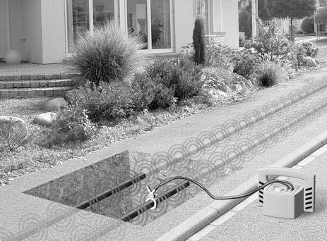
6 Unpacking And Inspection Your shipping carton should include: 1 R-3500 Receiver 1 T-3500 Transmitter 2 Measurement Cables 2 Alligator Clips 1 Grounding Rod 10 Battery IEC R6/AA Cell /Migon 6 IEC R20/ D Cell/ Mono 1 Nylon Bag Introduction The AT-3500 underground cable/pipe locator system is designed for the uncomplicated and user-friendly determination of the location, orientation and depth of metallic lines (e.g. cable and pipe lines). It can be used to probe areas for unknown lines or for locating specific lines. The AT-3500 is distinguished by the following features: Robust construction for use in poor weather and in harsh environments Simple, user-friendly operation concept with a minimum number of controls Reliable battery status indicator Operation 1. Decide which mode of operation to use for your application Induction: Transmitter s signal is emitted through the integrated antenna and is thereby inductively coupled with any metallic lines located within a certain radius. i. Place the T-3500 transmitter on the site to be searched. Refer to Figs.1, 2.3&4. Direct Connection: Transmitter s signal is directly coupled with a metallic line via the measurement cable which is connected to the jacks on the front panel of the transmitter. Transmitter clamps, alligator clips or power socket adapters (for example) may be used to connect the measurement cable to the lines. i. Connect the T-3500 transmitter to the line to be located using the desired method. Refer to Figs 1, 2, 3, & 4 T-3500 Transmitter 2. Push and Hold ON/OFF button to switch on the T Push Mode: C to select direct coupling or inductive coupling Direct coupling Green LED blinking: good (low-resistance) connection Alternating red and green LED blinking: sufficient connection Red LED blinking: poor/no (high-resistance) connection Inductive Coupling: Green LED blinking: induction mode is active 4. Push Signal Type: M to select Pulsed or Continuous signal Pulsed Signal is helpful when there is interference. Easier to distinguish from other signals. Continuous Signal is better to be used when taking a depth measurement Green LED blinking indicates respective signal is on 5. Push Signal Strength: P to select low (0.1W) or High(0.5W) output signal strength Low output (0.1W) for normal tracing. Battery saving High output(0.5w) for long tracing Green LED blinking indicates respective signal is on R-3500 Receiver 6. Push and Hold the Control1 button 7. Push briefly the ON/OFF button while holding control1 button Listen for the audible signal before releasing control1 The display shows the following: Push control3 to select the unit of measurement (meter or ft ) 9. Push Control1 to select normal depth measurement or depth measurement using the mouse 5
7 10. Push OK button to save the setting. An audible sound is heard The display shows the main menu: 11. Push Control3 to select the mode of operation Radio for locating cables carrying VLF re-radiated radio signals (No need for T-3500) Power Grid for locating main power cables that carry electrical current (No need for T-3500) Transmitter for locating cables or pipes carrying the signal of the T-3500 transmitter. 12. Push Control2 twice rapidly to select automatic or manual sensitivity adjustment Automatic sensitivity adjustment: Manual Sensitivity adjustment: i. Push control1 to decrease sensitivity adjustment ii. Push control3 to increase sensitivity adjustment iii. Push Control2 to start a depth measurement. 13. Hold the R-3500 receiver in an upright position in front of you as close to the ground as possible. Refer to Fig. 1. Receiver in line with the conductor Maximum signal strength Receiver perpendicular to the conductor minimum signal strength Applications and principles of direct coupling 1. Single-wire cables or pipes (with or without insulation against ground) The distance between the grounding rod and the ends of the connected lines should be as great as possible because return current tends to flow through the earth into adjacent lines, which could result in their path being followed. 2. Single-wire cable with metallic screen and ground insulation Short circuit between internal conductor and screen at the end of the cable with ground at the beginning and end of the cable as well. Failure to make the connection as shown will result in current cancellation from the internal conductor and the return current in the screen. Under certain circumstances this can prevent the cable from being detected. 3. Multiple-wire cable (internal conductor connected or disconnected) with metallic screen and grounding insulation Same application as in example 1 4. Metallic conduit (with or without insulation) the grounding rod and the conduit should be spaced as far apart as possible. Under certain circumstances, optimum positioning of the grounding rod may require several attempts. 5. If a return wire is available the spacing of the return wire should correspond to at least 10 times the depth of the line being located. 6. Pair of wires (with or without screen) with short circuit at the end of the cable For twisted cable pair (with a length of lay of the twist greater or equal to the laying depth), the orientation of the cable can be easily determined. 6
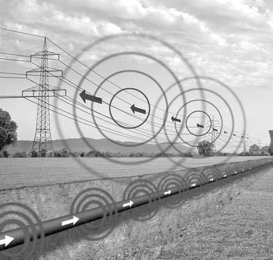
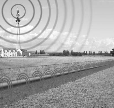
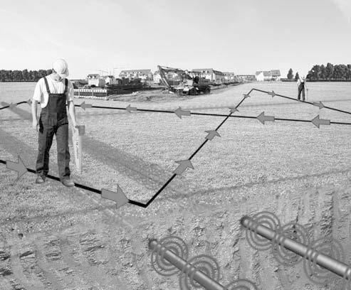
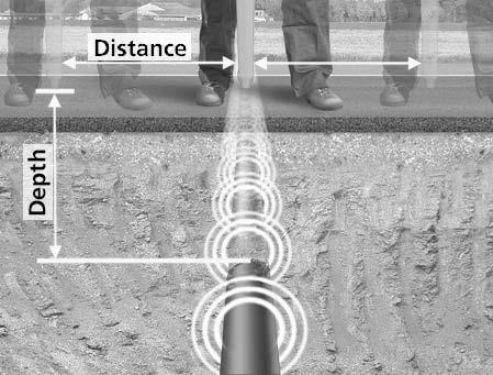
8 Adjacent lines which are horizontal to each other Minimum of the reception signal Lines situated on top of each other vertically Maximum of the reception signal Direct Coupling (Refer to Fig. 2.) 1. Connect the red test lead of the T-3500 transmitter with the conductor to be traced 2. Connect the black test lead of the T-3500 transmitter to ground using the grounding rod. Alternatively the black test lead may be clipped to the rim of a valve box or manhole cover. 3. Switch the T-3500 on 4. Select pulse or continuous signal transmission 5. Switch the R-3500 Receiver on 6. Begin to trace the cable from the point of application about 50-FT (15m) away 7. Move slowly over the cable. Decrease or increase the sensitivity as needed Direct Coupling using the A-3500 Clamp (Refer to Fig. 3.) 1. Plug the SC-3500 clamp into the T-3500 transmitter connection socket 2. Place the clamp around the pipe or cable 3. Switch the T-3500 transmitter on 4. Set the T-3500 transmitter to pulse or continuous signal transmission 5. Switch the R-3500 Receiver on 6. Select transmitter 7. Begin to trace the cable from the point of application about 15m away Inductive Coupling (Refer to Fig. 4.) 1. Position the T-3500 transmitter above the presumed cable 2. Switch on the T-3500 transmitter 3. Switch on the R-3500 receiver 4. Select the appropriate mode. Refer to section: Operation:R Begin to trace the line from the transmitter at least 15m away. 6. Make sure that a distance of at least 50-FT (15m) is always maintained between the receiver and transmitter in order to prevent the coupling of the transmitter s signal through the air. Locating Passive Lines (Radio and Power Modes) (Refer to Fig. 5.) The R-3500 Receiver can locate passive cables that carry radio signals in the frequency range between 15 khz and 23 khz as well as power signals between the range of 50 Hz and 60 Hz without the help of the T-3500 Transmitter. 1. Turn the R-3500 Receiver on 2. Select radio mode or power mode. Refer to section 8 OPERATION. 3. Set the sensitivity to maximum 4. Sweep the area using a grid pattern as shown below 5. Adjust the sensitivity to pinpoint the conductor 6. Rotate the R-3500 to find the maximum response Locating unknown cables (Refer to Fig. 6.) 1. Use the T-3500 Transmitter using the inductive mode. 2. Use the R-3500 Receiver to sweep the area. Keep the receiver 50-FT (15m) apart from the transmitter. 3. Select the desired mode of operation. 4. Adjust the sensitivity of the R-3500 as needed 5. When a conductor is located, pinpoint the strongest signal and mark the location 6. Repeat steps 1 and 2. Move the transmitter at least 3.3-FT (1m) and 90-degree from the initial position. 7. Repeat the process until the right cable is detected. Depth Measurement (Refer to Fig. 7.) 1. Connect the T-3500 transmitter with the cable or the metallic pipe 2. Turn the T-3500 transmitter on. Use continuous signal mode for better result 3. Turn the R-3500 receiver on and move at least 50-FT (15m) away from the transmitter 4. Rotate the R-3500 receiver until the maximum signal strength is detected 5. Push control1 to take an automatic depth measurement 6. The measurement will display as follow: 7. To change the unit of measure, refer to R-3500 mode of operation (section 8). 8. For non-metallic pipe, use the M-3000 mouse. Refer to R-3500 receiver mode of operation section 9 to set the receiver accordingly. 7
9 9. For Power and Radio signals, an estimated depth measurement can be taken as follow: a. Push control3 to select Power or Radio mode b. Move to one side of the suspected cable until the following symbol appears: c. Mark the spot d. Move to the other side until the symbol appears again e. Mark the spot f. Measure the distance between the two spots g. Divide the measurement by 2 to find the depth of the cable. Error messages during a depth measurement Symbol Meaning For of one of the following reasons, the depth could not be measured: The signal received was too weak or too irregular. The receiver was not held steady enough during the measuring process. The receiver was not positioned directly above the line at the beginning of the process. The depth of the metallic conductor amounts to more than 5 m (16 ft). The depth of the metallic conductor amounts to less than 30 cm (1 ft). Such conductors must be specially marked in order to prevent damage during construction. The receiver was moved too far to the left or right while making a rough estimate. Move in the opposite direction until the following symbol appears: Technical Specifications R-3500 The following parameters are specified for the R-3500 receiver: Frequency ranges Range 1: radio 15 khz to 23 khz Range 2: power network 50 Hz / 60 Hz; optionally 100 Hz (can be adjusted by Amprobe service personnel) Range 3: transmitter khz Sensitivity at a depth of 1m Range 1: radio >20 µa Range 2: power network >7 ma Range 3: transmitter >5 µa Dynamic response range Range 1: radio Range 2: power network Range 3: transmitter 120 db 135 db 120 db Depth determination Depth range 0.1 m 5 m (4 in 16 ft) 8
10 Resolution 0.1 m Accuracy - Range 1: radio ±20 % - Range 2: power network ±20 % - Range 3: transmitter ±5 % (>5m (6-FT)), ±20 % (<5m (15-FT)) Power supply Operating time 10 x IEC R6 / AA cell / Mignon 40 hours (for intermittent use with alkaline batteries, 20 C) Temperature range in accordance with DIN EN Operation -20 C to +55 C Storage -30 C to +70 C Weight Dimensions (W x H x D) 2.5 kg, 5.51 lbs. 99 x 660 x 252 mm,.3.90 x 25.98x 9.92 in Type of protection in accordance with EN Dust and water protected IP 67 from the lower edge of the receiver up to the lower edge of the battery compartment, and IP 56 for all parts above this delineation T-3500 The following parameters are specified for the T-3500 transmitter: Transmitted power 0.1 W / 0.5 W (switchable) Frequency khz Power supply 6 x IEC R20 / D cell / Mono Operating time 40 hours (for intermittent use with alkaline batteries, 20 C) Temperature range in accordance with DIN EN Operation -20 C to +55 C Storage -30 C to +70 C Weight Dimensions (W x H x D) 1.7 kg, 3.75 lbs. 260 x 255 x 140 mm, Type of protection in accordance with EN Dust and water protected IP 56 Maintenance Changing the battery in the R-3500 receiver The status of the receiver s batteries is checked upon start-up and indicated in the display. The system regularly checks the battery strength as well. If battery capacity falls below 10 % of the threshold value, an audible warning signal is given and the current status of the batteries is shown in the upper part of the display. 9
 batteries, the battery housing must be removed as")


11 In order to replace the ten 1.5 V mignon (AA) batteries, the battery housing must be removed as described in the following illustrations: Changing the batteries in the T-3500 transmitter The batteries in the transmitter have to be replaced as soon as the red LED battery indicator starts to blink. Should this occur while the user is busy locating a line with the receiver, he/she will be informed of the weak batteries via the reception signal: Ty pe of signal Normal signal Signal when batteries are weak In order to change the six 1.5 V mono (D cell) batteries, both screws on the back of the transmitter must be (e.g. with the aid of a coin) turned through ¼ turn (1) and the battery tray must be pulled (2). Please note that all the batteries are fitted in the same direction. 10
. Replacements can be ordered through the SEBA KMT sales team.")
12 Changing the floor cap on the R-3500 receiver The plastic floor cap, which prevents the tip of the receiver from being damaged, can be easily replaced with the aid of a pointed object (e.g. screw driver). Replacements can be ordered through the SEBA KMT sales team. 11


13 Fig. 1 Fig. 2 Fig. 3 12

14 Fig. 4 Fig. 5 Fig. 6 13
15 Fig. 7 14
For detailed specifications and ordering info go to
 For detailed specifications and ordering info go to www.testequipmentdepot.com ECB50A, ECB50A-E, ECB50A-FGIS Circuit Breaker Finder and AC Cable Tracer User Manual For detailed specifications and ordering
AT Advanced Wire Tracer. Users Manual
 AT-1000 Advanced Wire Tracer Users Manual AT-1000 Advanced Wire Tracer English Users Manual AT1000_Rev001 2008 Amprobe Test Tools. All rights reserved. Limited Warranty and Limitation of Liability Your
Circuit Breaker Finder
 ECB50-FGIS Circuit Breaker Finder and AC Line Tracer User Manual ECB50-FGIS Circuit Breaker Finder and AC Cable Tracer Contents Safety Information...3 Symbols Used in this Manual...3 Introduction...4 Finding
CT238A. AC/DC Current Probe. User Manual. For detailed specifications and ordering info go to
 CT238A AC/DC Current Probe User Manual For detailed specifications and ordering info go to www.testequipmentdepot.com CT238A AC/DC Current Probe User Manual English Limited Warranty and Limitation of Liability
AT-4000 Series. Advanced Wire Tracer. Users Manual
 AT-4000 Series Advanced Wire Tracer Users Manual AT-4000 Series Advanced Wire Tracer English Users Manual AT4000CON_Rev001 2008 Amprobe Test Tools. All rights reserved. 1 Limited Warranty and Limitation
A Sheath Fault Locator. 99 Washington Street Melrose, MA Phone Toll Free
 99 Washington Street Melrose, MA 02176 Phone 781-665-1400 Toll Free 1-800-517-8431 Visit us at www.testequipmentdepot.com A-5000 Sheath Fault Locator Users Manual A-5000 Sheath Fault Locator English Users
Dynatel 2250E/2273E Advanced Cable and Fault Locator
 Dynatel 2250E/2273E Advanced Cable and Fault Locator Operators Manual September 1999 78-8097-6500-7-B TABLE OF CONTENTS Introduction... 2 Installing or Replacing the Batteries... 2 Initial Receiver Configuration...
AM-510 Commercial / Residential Multimeter. AM-510-EUR Digital Multimeter. Users Manual
 AM-510 Commercial / Residential Multimeter AM-510-EUR Digital Multimeter Users Manual AM-510 Commercial / Residential Multimeter AM-510-EUR Digital Multimeter English Users Manual Limited Warranty and
AM-500 Autoranging Mulitmeter. AM-500-EUR Digital Multimeter. Users Manual
 AM-500 Autoranging Mulitmeter AM-500-EUR Digital Multimeter Users Manual AM-500 Autoranging Mulitmeter AM-500-EUR Digital Multimeter English Users Manual 8/2012, 4275548 A 2012 Amprobe Test Tools. All
STAFF User Manual. Manual Part #
 STAFF User Manual Manual Part # 030-00085-00 Introduction Congratulations on the purchase of your new STAFF Secondary Fault Locator. The STAFF is specially designed to detect conductor to earth/ground
POWER TRACE TM TASCO, INC.
 POWER TRACE TM Instruction Manual PTL610 TASCO, INC. HOW YOUR POWER TRACE TM OPERATES The Power Trace TM is composed of two primary components: the Receiver and the Transmitter. When the Transmitter is
MICROTOOLS MICRONETBLINK KIT
 MICROTOOLS MICRONETBLINK KIT MicroNetBlink TM MicroProbe TM User Guide Manuel Utilisateur Benutzer Handbuch Manuale per l'utente Guía del Usuario Manual do Utilizador 2947-4511-01 Rev. 01 11/01 2001 Fluke
AC68C. Users Manual. True RMS AC/DC Clamp Multimeter. PN July Amprobe Test Tools. All rights reserved.
 AC68C True RMS AC/DC Clamp Multimeter Users Manual PN 2729051 July 2006 2006 Amprobe Test Tools. All rights reserved. Printed in Taiwan For detailed specifications and ordering info go to www.testequipmentdepot.com
Pro871C Cable Locator Operating Instructions
 Pro871C Cable Locator Operating Instructions WARNING Read and understand the instructions before operating this unit. Failure to do so could lead to injury or death. The Armada Technologies Pro871C wire
INDEX PREFACE... 1 CAUTIONS... 2 OPERATION ON SITE(9) STANDARD INSTRUMENT... 3 OPTIONAL ACCESSORIES... 4 OPERATION OF TRANSMITTER(3)...
 STANDARD INSTRUMENT... 3 OPTIONAL ACCESSORIES... 4 OPERATION OF TRANSMITTER(3)...") INDEX PREFACE... 1 CAUTIONS... 2 STANDARD INSTRUMENT... 3 OPTIONAL ACCESSORIES... 4 OPERATION OF TRANSMITTER(1)... 5 (Transmitter Unit.) OPERATION OF TRANSMITTER(2)... 6 (Operation Panel, LCD Display of
INDEX PREFACE... 1 CAUTIONS... 2 STANDARD INSTRUMENT... 3 OPTIONAL ACCESSORIES... 4 OPERATION OF TRANSMITTER(1)... 5 (Transmitter Unit.) OPERATION OF TRANSMITTER(2)... 6 (Operation Panel, LCD Display of
Obsolete Document. Dynatel
 3 Dynatel 2273ME Cable/Pipe and Fault Locators 2273ME-iD Cable/Pipe/Fault and Marker Locators with id Read/Write 2250ME Cable/Pipe Locators 2250ME-iD Cable/Pipe and Marker Locators with id Read/Write New-to-the-world
AM-520 AM-530. Users Manual. HVAC Multimeter. True-rms Electrical Contractor Multimeter
 AM-520 HVAC Multimeter AM-530 True-rms Electrical Contractor Multimeter Users Manual 99 Washington Street Melrose, MA 02176 Phone 781-665-1400 Toll Free 1-800-517-8431 Visit us at www.testequipmentdepot.com
The table below lists the symbols used on the Clamp and/or in this manual. Important Information. See manual.
 i310s AC/DC Current Clamp Instruction Sheet Introduction The i310s Current Clamp ( Clamp ) has been designed for use with oscilloscopes and digital multimeters for accurate nonintrusive measurement of
Specifications for 3M Dynatel 2273M/M-iD Cable/Pipe and Fault Locators
 Specifications for 3M Dynatel 2273M/M-iD Cable/Pipe and Fault Locators PHYSICAL SPECIFICATIONS SIZE WEIGHT (H X W X D) IN. (CM) (INCLUDING BATTERIES) Transmitter 6.75 x 11.25 x 7.75 (17.2 x 28.6 x 19.7)
DOCUMENT OBSOLETE. Dynatel. 2273M Cable/Pipe and Fault Locators 2273M-iD Cable/Pipe/Fault and Marker Locators with id Read/Write
 3 Dynatel 2273M Cable/Pipe and Fault Locators 2273M-iD Cable/Pipe/Fault and Marker Locators with id Read/Write New-to-the-world technology for locating underground utilities without any doubt. The 3M Dynatel
8873 v3 Pathfinder Locator User Manual
 8873 v3 Pathfinder Locator User Manual Manual Part # 030-00100-00 Rev B Table of Contents General Information Introduction...2 Prepare for Use....2 Receiver Operation.......................................
UAT-600 Series. amprobe.com
 UAT-600 Series Underground Utilities Locator Accurately and safely pinpoint underground utilities before you dig Accidentally hitting a utility line during a project can lead to costly repairs and create
Using the USB Output Port to Charge a Device
 Table of Contents ----------------------------------- 2 Features ----------------------------------------------- 3 Controls and Functions ---------------------------------- 4 ER210 Power Sources -----------------------------------
AMP-25 AMP-25-EUR. Mini-Clamp TRMS AC / AMP-25. ZERO 2 Sec
 AMP-25 AMP-25-EUR Mini-Clamp TRMS AC / ZERO 2 Sec AMP-25 AMP-25 AMP-25-EUR Mini-Clamp User Manual English 1/2015, 6004363 B 2015 Amprobe Test Tools. All rights reserved. Printed in Taiwan Limited Warranty
ER200 COMPACT EMERGENCY CRANK DIGITAL WEATHER ALERT RADIO OWNER S MANUAL
 ER200 COMPACT EMERGENCY CRANK DIGITAL WEATHER ALERT RADIO OWNER S MANUAL Table of Contents -------------------------------------- 2 Features ----------------------------------------------- 3 Controls and
900MHz Digital Hybrid Wireless Outdoor Speakers
 4015004 900MHz Digital Hybrid Wireless Outdoor Speakers User s Manual This 900 MHz digital hybrid wireless speaker system uses the latest wireless technology that enables you to enjoy music and TV sound
36 AC/DC True RMS. Clamp Meter. P Read First: Safety Information
 36 / True RMS Clamp Meter Instruction Sheet P Read First: Safety Information To ensure safe operation and service of the meter, follow these instructions: Avoid working alone so assistance can be rendered.
2011 / Circuit Tracer
 INSTRUCTION MANUAL 2011 / 00521 Circuit Tracer Read and understand all of the instructions and safety information in this manual before operating or servicing this tool. 52044992 2008 Greenlee Textron
F I S H E R R E S E A R C H L A B O R A T O R Y
 TW-82 DIGITAL LINE TRACER Operating Manual F I S H E R R E S E A R C H L A B O R A T O R Y CONTENTS Introduction...pg. 3 Transmitter...pg. 4-5 Receiver...pg. 6-8 Operating Instructions...pg. 9 Specifications...pg.
Supplement. Title: 30XR-A Users Supplement Issue: 1 Part Number: Issue Date: 9/06 Print Date: July 2006 Page Count: 1 Revision/Date:
 Supplement Title: Users Supplement Issue: Part Number: 7897 Issue Date: 9/06 Print Date: July 006 Page Count: Revision/Date: This supplement contains information necessary to ensure the accuracy of the
ACD-3300 IND ACDC-3400 IND
 ACD-3300 IND ACDC-3400 IND CAT IV Industrial True RMS Clamp Meters Users Manual Mode d emploi edienungshandbuch Manuale d Uso Manual de uso Användarhandbok 99 Washington Street Melrose, MA 02176 Phone
Broadband Current Probe Series Operation Manual
 Broadband Current Probe Series Operation Manual 1 TABLE OF CONTENTS INTRODUCTION 3 GENERAL INFORMATION 4 OPERATING INSTRUCTIONS 5 FORMULAS 6 MAINTENANCE 7 WARRANTY 8 2 INTRODUCTION CURRENT PROBE SPECIFICATIONS
Broadband Current Probe Series Operation Manual
 Broadband Current Probe Series Operation Manual 1 TABLE OF CONTENTS WARRANTY 3 INTRODUCTION 4 GENERAL INFORMATION 5 OPERATING INSTRUCTIONS 6 FORMULAS 7 MAINTENANCE 8 2 WARRANTY INFORMATION A.H. Systems
Acu-Park TM. user s guide Directed Electronics, Inc. Vista, CA N9100T 09-04
 Acu-Park TM user s guide 2004 Directed Electronics, Inc. Vista, CA N9100T 09-04 limited one year warranty Directed Electronics, Inc. (hereinafter "Directed") promises to the original purchaser that this
Armada Technologies Pro800D Hi-Power Wire and Valve Locator. Operating Instructions
 Test Equipment Depot - 800.517.8431-99 Washington Street Melrose, MA 02176 TestEquipmentDepot.com Armada Technologies Pro800D Hi-Power Wire and Valve Locator Armada T echnologies Operating P ro800d Instructions
DynatelTM Cable Locator. Operators Manual. October Revision A
 DynatelTM 2210 Cable Locator Operators Manual October 1996 78 8097 5171 8 Revision A 3M TM Dynatel TM 2210 Cable Locator Operators Manual The information in this manual is proprietary to 3M and may not
99 Washington Street Melrose, MA Fax TestEquipmentDepot.com # # AAC Clamp Meter. Instruction Manual
 99 Washington Street Melrose, MA 02176 Fax 781-665-0780 TestEquipmentDepot.com #61-732 #61-736 400 AAC Clamp Meter Instruction Manual AC HOLD APO DC KMΩ mva WARNING Read First: Safety Information Understand
TW-82 TW-82 ACCESSORIES. Operating Manual DIGITAL LINE TRACER F I S H E R R E S E A R C H L A B O R A T O R Y
 TW-82 ACCESSORIES 3 Inch Coupling Clamp CCLAMP-3 Useful for in-service and electrical power line tracing when a metal-to-metal hookup is not possible TW-82 DIGITAL LINE TRACER 5 Inch Coupling Clamp CCLAMP-5
TAG5000 WIRELESS PHASER. Instruction Manual HD ELECTRIC COMPANY 1475 LAKESIDE DRIVE WAUKEGAN, ILLINOIS U.S.A.
 TAG5000 WIRELESS PHASER Instruction Manual TM HD ELECTRIC COMPANY 1475 LAKESIDE DRIVE WAUKEGAN, ILLINOIS 60085 U.S.A. PHONE 847.473.4980 FAX 847.473.4981 website: www.hdelectriccompany.com DESCRIPTION
AM-540 AM-550. AM-540-EUR AM-550-EUR Digital Multimeter. Users Manual. Advanced HVAC Multimeter. Industrial Multimeter
 AM-540 Advanced HVAC Multimeter AM-550 Industrial Multimeter AM-540-EUR AM-550-EUR Digital Multimeter Users Manual 99 Washington Street Melrose, MA 02176 Phone 781-665-1400 Toll Free 1-800-517-8431 Visit
Mo d e l Ma g h o r n Ma g n e t ic Lo c a t o r
 Mo d e l 4 5 0 Ma g h o r n Ma g n e t ic Lo c a t o r Us e r s Ma n u a l Manufactured Exclusively By: Utility Tool Company, Inc. 2900 Commerce Boulevard Birmingham, Alabama 35210 205-956-3710 User s
ACD-14 FX ACD-14 TRMS FX
 ACD-14 FX ACD-14 TRMS FX User Manual Bedienungshandbuch Mode d emploi Manuale d Uso Manual de uso Bruksanvisning ACD-14 FX ACD-14 TRMS FX Owner s Manual Limited Warranty and Limitation of Liability Your
User s Guide. 400A AC/DC Clamp Meter. Model MA220
 User s Guide 400A AC/DC Clamp Meter Model MA220 Introduction Thank you for selecting the Extech MA200 AC/DC Clamp Meter. This meter measures AC/DC Current, AC/DC Voltage, Resistance, Capacitance, Frequency,
SIR-WRR1. User's Guide SIRIUS Echo Antenna. Signal Repeater System Accessory
 SIR-WRR1 User's Guide SIRIUS Echo Antenna Signal Repeater System Accessory Desktop SIRIUS Docking Echo Station Antenna FCC NOTICE: This device complies with part 15 of the FCC Rules and with RSS-210 of
712B. Users Manual. RTD Calibrator. Test Equipment Depot Washington Street Melrose, MA TestEquipmentDepot.
 712B RTD Calibrator Test Equipment Depot - 800.517.8431-99 Washington Street Melrose, MA 02176 - TestEquipmentDepot.com Users Manual January 2014 2014 Fluke Corporation. All rights reserved. Specifications
Pro. SimpliFiber. Getting Started Guide. Optical Power Meter and Fiber Test Kits
 SimpliFiber Pro Optical Power Meter and Fiber Test Kits Getting Started Guide PN 3314816 September 2008, Rev. 2 6/12 2008, 2010, 2012 Fluke Corporation. Printed in USA. All product names are trademarks
DE EN FR ECOLINE EL 609 BEDIENUNGSANLEITUNG USER MANUAL MODE D EMPLOI EXACTLY WHAT YOU NEED.
 DE FR ECOLINE EL 609 BEDIUNGSANLEITUNG USER MANUAL MODE D EMPLOI EXACTLY WHAT YOU NEED. 1 FEATURES OPERATIONAL ELEMTS 1 vertical and 1 horizontal laser line form 1 laser cross Laser lines switchable separately
HART Mode. Users Guide. July Fluke Corporation. All rights reserved. All product names are trademarks of their respective companies.
 754 HART Mode Users Guide July 2011 2011 Fluke Corporation. All rights reserved. All product names are trademarks of their respective companies. LIMITED WARRANTY AND LIMITATION OF LIABILITY This Fluke
TW-82 DIGITAL LINE TRACER. Operating Manual
 TW-82 DIGITAL LINE TRACER Operating Manual CONTENTS Introduction... pg. 3 Transmitter...pg. 4-6 Receiver...pg. 7-9 Specifications...pg. 10 Warranty...pg. 11 Accessories...pg. 12 INTRODUCTION The TW-82
200Amp AC Clamp Meter + NCV Model MA250
 User's Guide 200Amp AC Clamp Meter + NCV Model MA250 Introduction Congratulations on your purchase of this Extech MA250 Clamp Meter. This meter measures AC Current, AC/DC Voltage, Resistance, Capacitance,
2001A. 200KHz Function Generator Instruction Manual. 99 Washington Street Melrose, MA Phone Toll Free
 2001A 200KHz Function Generator Instruction Manual 99 Washington Street Melrose, MA 02176 Phone 781-665-1400 Toll Free 1-800-517-8431 Visit us at www.testequipmentdepot.com WARRANTY Global Specialties
Schooners II. Weatherproof Wireless 900MHz Speaker System. User Guide. Model no.: GDI-AQSHR200 / AQSHR21
 Schooners II Weatherproof Wireless 900MHz Speaker System User Guide Model no.: GDI-AQSHR200 / AQSHR21 IMPORTANT: Please read your User s Guide before using your system INTRODUCTION Your SCHOONERS II speaker
netzerotools.com 374/375/376 Users Manual Clamp Meter
 374/375/376 Clamp Meter Users Manual Fluke 376 True RMS AC DC Clamp Meter Fluke 374 True RMS AC / DC Clamp Meter Fluke 373 True RMS AC Clamp Meter Fluke 375 True RMS AC / DC Clamp Meter LIMITED WARRANTY
PM55A. Automatic Precision Pocket Meter. English. Users Manual. PN July Amprobe Test Tools. All rights reserved.
 PM55A Automatic Precision Pocket Meter Users Manual English PN 2728864 July 2006 2006 Amprobe Test Tools. All rights reserved. Printed in Taiwan For detailed specifications and ordering info go to www.testequipmentdepot.com
HHMA2 DC / TRUE RMS AC NON-CONTACT MILLIAMMETER
 HHMA2 DC / TRUE RMS AC NON-CONTACT MILLIAMMETER Instruction Manual Manual UN-01-249 Item 359934 April, 1999 Rev. -- OMEGA Engineering Inc. All rights reserved. This symbol appears on the instrument and
T+ and T+ PRO Electrical Tester
 T+ and T+ PRO Electrical Tester Instruction Sheet Introduction The Fluke T+ and T+ PRO Electrical Testers (the Tester ) have the following features: AC and dc voltage measurement, 12 V to 600 V, with or
vscan Data Sheet V1.0
 A. The vscan System The vscan receiver, and (optional) transmitter, are used for locating buried utilities. The vscanm incorporates all the vscan features plus a metal cover locating mode. The system is
TW-82 TW-82 ACCESSORIES. Operating Manual Revision Level 1 DIGITAL LINE TRACER
 TW-82 ACCESSORIES 3-Inch Coupling Clamp CCLAMP-3 Useful for in-service and electrical power line tracing when a metal-to-metal hookup is not possible TW-82 DIGITAL LINE TRACER 5-Inch Coupling Clamp CCLAMP-5
TW-82. Operating Manual DIGITAL LINE TRACER. Revision Level 1
 TW-82 DIGITAL LINE TRACER Operating Manual Revision Level 1 CONTENTS Introduction... 3 Transmitter... 4-6 Receiver... 7-13 Power-On...7 Lateral Mode... 8-10 Unit Of Measure... 11 Display... 11-13 Auto
C.A.T and Genny User Guide. Revision
 C.A.T and Genny User Guide Revision 3-06.00 Troubleshooting When reporting any problem to your Radiodetection Dealer/Supplier it is important to quote the Receiver Serial Number. Warning: Radiodetection
374/375/376 Clamp Meter
 374/375/376 Clamp Meter Users Manual PN 3608883 July 2010 2010 Fluke Corporation. All rights reserved. Printed in China. Specifications are subject to change without notice. All product names are trademarks
f i r e - p a r t s. c o m
 Model: CON 1001-1 INSTALLATION AND OPERATING INSTRUCTIONS SINGLE-FUNCTION WIRELESS REMOTE CONTROL SYSTEM FOR OPERATING VALVES WITH ON/OFF LATCHING SOLENOIDS IF YOU CANNOT READ OR UNDERSTAND THESE INSTALLATION
Dynatel Cable/Pipe and Fault Locator 2273M Cable/Pipe, Fault and Marker Locator 2273M-iD
 Dynatel Cable/Pipe and Fault Locator 2273M Cable/Pipe, Fault and Marker Locator 2273M-iD GPS Interface Allows Real-Time Mapping Innovative technology for locating underground utilities without any doubt
DA560D COMPACT SERIES. INSTALLATION / OWNER'S MANUAL Mobile Power Amplifiers
 DA560D COMPACT SERIES INSTALLATION / OWNER'S MANUAL Mobile Power Amplifiers Preparation Please read entire manual before installation. Due to the technical nature of amplifiers, it is highly recommended
Glass Electrode Meter
 Glass Electrode Meter INSTRUCTION MANUAL FOR Glass Electrode R/C Meter MODEL 2700 Serial # Date PO Box 850 Carlsborg, WA 98324 U.S.A. 360-683-8300 800-426-1306 FAX: 360-683-3525 http://www.a-msystems.com
DIGITAL DUAL DISPLAY AC/DC CLAMP METER MODEL- KM 2782 / 2782-T
 DIGITAL DUAL DISPLAY AC/DC CLAMP METER MODEL- KM 2782 / 2782-T KM 2782 V 400A POWER G 17,Bharat Industrial Estate, T. J. Road, Sewree (W), Mumbai - 400 015. INDIA. Sales Direct : (022) 24156638 Tel. :
BC Link 2.0 Owner s Manual
 Owner s Manual Table of Contents DISCLAIMER...2 COMPONENT OUTLINE...2 GETTING STARTED...3 Charging battery...3 Connecting Smart Mic...3 Attaching to backpack...3 BASIC FUNCTIONS...4 User interface...4
Advanced Test Equipment Rentals ATEC (2832)
") Established 1981 Advanced Test Equipment Rentals www.atecorp.com 800-404-ATEC (2832) A.H. Systems Model Active Monopole Antennas Active Monopole Antenna Series Operation Manual 1 TABLE OF CONTENTS INTRODUCTION
Established 1981 Advanced Test Equipment Rentals www.atecorp.com 800-404-ATEC (2832) A.H. Systems Model Active Monopole Antennas Active Monopole Antenna Series Operation Manual 1 TABLE OF CONTENTS INTRODUCTION
374/375/376 Clamp Meter
 374/375/376 Clamp Meter Users Manual PN 3608883 July 2010 2010 Fluke Corporation. All rights reserved. Printed in China. Specifications are subject to change without notice. All product names are trademarks
Broadband Step-Up Transformer. User Manual
 Broadband Step-Up Transformer User Manual 990-1930 09/2004 Introduction Introduction About this unit The APC Step-Up Transformer provides 220 V power from 60 VAC Broadband cable systems. Safety Electrical
INSTRUCTION MANUAL MARTINDALE EZ150 / EZ650 SOCKET TESTER 1. INTRODUCTION. ELECTRIC Trusted by professionals
 EZ150 / EZ650 SOCKET TESTER INSTRUCTION MANUAL GENERAL SAFETY INFORMATION: Always read before proceeding. These instructions contain both information and warnings that are necessary for the safe operation
FR250 OPERATION MANUAL
 www.etoncorp.com FR250 OPERATION MANUAL SELF-POWERED RADIO AND FLASHLIGHT FR250 AM/FM Shortwave radio, flashlight, and cell phone charger TABLE OF CONTENTS DO YOU NEED HELP? We want you to thoroughly enjoy
312, 316, 318. Clamp Meter. Users Manual
 312, 316, 318 Clamp Meter Users Manual PN 1989445 July 2002 Rev.2, 2/06 2002, 2006 Fluke Corporation. All rights reserved. Printed in China. All product names are trademarks of their respective companies.
MS6813. Users Manual TEST BNC MS6813 TRANSMITTER SHIELD OFF CONT TONE. Multi-Function Wire Tracer. Short Reversed Miswire Split Pairs
 Multi-Function Wire Tracer Users Manual MS6813 RJ45 CO-AX RJJJ Multi-Function Wire Tracer 1-2 3-6 4-5 7-8 SHIELD Short Reversed Miswire Split Pairs TEST CONT OFF TONE red fauit green good BNC 10 Base T
DA6002D-DA10004D. INSTALLATION / OWNER'S MANUAL Mobile Power Amplifiers
 DA6002D-DA10004D INSTALLATION / OWNER'S MANUAL Mobile Power Amplifiers Preparation Please read entire manual before installation. Due to the technical nature of amplifiers, it is highly recommended that
Instruction Manual ET4 ELECTRICAL TESTER
 ET4 ELECTRICAL TESTER Instruction Manual GENERAL SAFETY INFORMATION: Always read before proceeding. Warning These instructions contain both information and warnings that are necessary for the safe operation
DA604D DA954D DA501D DA801D COMPACT SERIES. INSTALLATION / OWNER'S MANUAL Mobile Power Amplifiers
 DA604D DA954D DA501D DA801D COMPACT SERIES INSTALLATION / OWNER'S MANUAL Mobile Power Amplifiers Preparation Please read entire manual before installation. Due to the technical nature of amplifiers, it
Loki Pipe & Cable Locators
 Loki Pipe & Cable Locators User guide 90/UG114INT CONTRACTOR MODEL UTILITIES MODEL IMPORTANT SAFETY NOTICE Risk of property damage, death, or serious injury may result if buried pipes and cables are not
Dawson DDM190. Digital Multimeter User s Manual
 Dawson DDM190 Digital Multimeter User s Manual TABLE OF CONTENTS LIMITED WARRANTY AND LIMITATION OF LIABILITY... 3 Out of the Box... 3 Accessories.. Error! Bookmark not defined. Safety Information... 7
Grid Radar Installation Manual
 Grid Radar Installation Manual MODELS GN-RD-001 120V Single Phase / Wye, 240V Single Phase, with Neutral GN-RD-002 277V 3-Phase Wye, with Neutral GN-RD-003 480V 3-Phase Delta, no Neutral GN-RD-004 208V
ER200 COMPACT EMERGENCY CRANK DIGITAL WEATHER ALERT RADIO OWNER S MANUAL
 ER200 COMPACT EMERGENCY CRANK DIGITAL WEATHER ALERT RADIO OWNER S MANUAL Table of Contents -------------------------------------- 2 Features ----------------------------------------------- 3 Controls and
INSTRUCTION MANUAL E1612 EARTH TESTER 1. INTRODUCTION
 E1612 EARTH TESTER INSTRUCTION MANUAL GENERAL SAFETY INFORMATION: Always read before proceeding. Warning These instructions contain both information and warnings that are necessary for the safe operation
A510S Operation Manual
 A510S Operation Manual REV 1.1 1 Table of Contents 1 General Information 1-1 Description 1-2 Potential Operational Hazards 1-3 Technical Specifications 1-4 Instrument Overview 1-5 Function Summary 2 How
F R F R G
 w w w. e t o n c o r p. c o m F R 2 0 0 F R 2 0 0 G O P E R AT I O N M A N U A L A M / F M / S H O R T W A V E R A D I O TABLE OF CONTENTS DO YOU NEED HELP? Contact Us. Etón Corporation 1015 Corporation
Receiver Type /Version Factory No. Frequency. Transmitter Type /Version Factory No. Frequency
 Receiver Type /Version Factory No. Frequency Transmitter Type /Version Factory No. Frequency 1. STANDARD SPECIFICATION Portable transmitter. Receiver with integrated mounting holes. Multi-pin connecting
INSTRUCTION MANUAL LM192 LIGHT METER ALWAYS READ THESE INSTRUCTIONS BEFORE PROCEEDING CONTENTS. Precautions 1. SAFETY INFORMATION
 ALWAYS READ THESE INSTRUCTIONS BEFORE PROCEEDING LM9 LIGHT METER Thank you for buying one of our products. For safety and a full understanding of its benefits please read this manual before use. Technical
Owner s Manual DKW-3 HT. Wireless VHF Microphone System
 Owner s Manual DKW-3 HT Wireless VHF Microphone System Contents Introduction... 2 System Features... 2 Operation... 3 Specifications... 5 Service Information... 6 Warranty... 7 Introduction Thank you for
Pocket Weatheradio with Tone and Vibrating Alert
 Pocket Weatheradio with Tone and Vibrating Alert OWNER S MANUAL Please read before using this equipment. Your RadioShack Pocket Weatheradio is designed to receive National Weather Service (NWS) broadcasts,
This manual applies to the WT-RC-Ex receiver when used to locate all makes and models of 22 Hz and Wavetrak coded transmitters.
 This manual applies to the WT-RC-Ex receiver when used to locate all makes and models of 22 Hz and Wavetrak coded transmitters. The Wavetrak WT-RC-Ex receiver kit comes with the following pieces of equipment:
User's Guide. Wireless AC Circuit Identifier. Models RT30 and RT32
 User's Guide Wireless AC Circuit Identifier Models RT30 and RT32 Introduction Congratulations on your purchase of Extech s Model RT30 (914Mhz) or RT32 (869MHz) Wireless AC Circuit Identifier. The detector
XPR522 XPR540. XPR SERIES INSTALLATION / OWNER'S MANUAL Mobile Power Amplifiers
 XPR522 XPR540 XPR SERIES INSTALLATION / OWNER'S MANUAL Mobile Power Amplifiers Preparation Please read entire manual before installation. Due to the technical nature of amplifiers, it is highly recommended
2000 A AC TRUE RMS DIGITAL CLAMP METER WITH NON-CONTACT EF-DETECTION
 An ISO 9001:2008 Company 2000 A AC TRUE RMS DIGITAL CLAMP METER WITH NON-CONTACT EF-DETECTION SPECIAL FEATURES : 2000A AC Clamp-on + Full Multimeter ranges AC True RMS Voltage & Current functions Autocheck
WireMaster Coax BNC PN: Rev C 2/13
 WireMaster Coax BNC Instruction Manual PN: 3274 84-868 Rev C 2/13 Table of Contents Features...... 2 Introduction... 3 Warnings and Cautions... 3 Specifications...4 Typical Cable/Wire Resistances...5 Control
Leica DIGISYSTEM TM Safe and fast location of underground services
 Leica DIGISYSTEM TM Safe and fast location of underground services Find it or avoid it the Leica DIGISYSTEM is your Key Why locate Construction sites have many and varied buried services and utilities.
Rock Sounders. Weatherproof Wireless 900MHz Speaker System. User Guide. Model no.: GDI-AQRCK400 / AQRCK41
 Rock Sounders Weatherproof Wireless 900MHz Speaker System User Guide Model no.: GDI-AQRCK400 / AQRCK41 Please read before using the equipment IMPORTANT: Please read your User s Guide before using your
Cable I.D. Live. Primary or Secondary In or Out of the Trench TX-Former to TX-Former TX-Former to Meter Energized or Grounded.
 Cable I.D. Live Primary or Secondary In or Out of the Trench TX-Former to TX-Former TX-Former to Meter Energized or Grounded www.aquatronics.com i ii TABLE OF CONTENTS Warning Description Battery Test
User s Guide. Model MA A AC Mini Clamp-on Meter
 User s Guide Model MA150 200A AC Mini Clamp-on Meter Introduction Congratulations on your purchase of Extech s MA150 AC Mini Clamp Meter. This meter is shipped fully tested and calibrated and, with proper
Leica Digisystem Safe and fast location of underground services
 Leica Digisystem Safe and fast location of underground services Leica Digisystem Making Cable Avoidance Easier and Safer Every year site workers are injured due to inadvertently striking buried utilities
AT-4000 Advanced Tracer User s Manual
 AT-4000 Advanced Tracer User s Manual Amprobe thanks you for purchasing the AT-4000 Advanced Tracer. For your safety, please read this instruction manual in its entirety. LIMITED WARRANTY VÉÇzÜtàâÄtà ÉÇá4
Armada Technologies Pro900 Advanced Underground Locator USER GUIDE
 Pro900 Advanced Underground Locator USER GUIDE WARNING Read and understand the instructions before operating this unit. Failure to do so could lead to injury or death. The Armada Technologies Pro900 Advanced