S-COM Controller Technical Training
|
|
|
- Steven George
- 6 years ago
- Views:
Transcription
1 S-COM Controller Technical Training Dave Maciorowski 12 February 2017 (Note: aligned with Release 1.6) Copyright 2014, SCOM, LLC
2 Getting These Slides 2
3 Agenda 3 Introduction Who is S-COM? The Basics Repeater Building Blocks What does a controller need to do? Common Terms Introducing the 7330 Wiring It Up Connectors, Jumpers, Pots Power Input Logic Signals Output Logic Signals Audio A-to-D Input Signals CTCSS Encoder Basic Programming Testing on the Bench Initializing the Controller S-COM Command Formats Security Data Types Introduction to the Manual Getting Started with Programming Commands Copyright Testing 2017, Your SCOM, Results LLC Advanced Programming Ports and Paths More About Messages Receiver Timing Macros CTCSS Encoder Scheduler File Management Introducing SBOOT PC-Based Utilities S-COM Custom Audio Utility Other Controller Topics Digital Linking: IRLP, EchoLink, Allstar
4 Agenda 4 Introduction Who is S-COM? The Basics Repeater Building Blocks What does a controller need to do? Common Terms Introducing the 7330 Wiring It Up Connectors, Jumpers, Pots Power Input Logic Signals Output Logic Signals Audio A-to-D Input Signals CTCSS Encoder Basic Programming Testing on the Bench Initializing the Controller S-COM Command Formats Security Data Types Introduction to the Manual Getting Started with Programming Commands Copyright Testing 2017, Your SCOM, Results LLC Advanced Programming Ports and Paths More About Messages Receiver Timing Macros CTCSS Encoder Scheduler File Management Introducing SBOOT PC-Based Utilities S-COM Custom Audio Utility Other Controller Topics Digital Linking: IRLP, EchoLink, Allstar

5 Introduction Who Is S-COM? Bob Schmid, WA9FBO Founder and Owner of S-COM, LLC Bob s first controller was a SWTPC 6800 microcomputer, assembled from a kit in 1976 and used to control WR9AIN, a Quintron repeater in New Holstein, WI. Wire-wrapped versions were followed by the Big Board controller introduced in The MRC-100 came out in 1984, followed by the 5K (1987), the 7K (1989), the 6K (1990), and the 7330 (2007), a total of about 4900 units. There are also customized controllers in commercial use, as well as air-to-ground interconnects for the airline industry. S-COM continues to ship 7330s and is busy defining the next generation of repeater controllers and accessories. 5 Dave Maciorowski, WA1JHK Hardware and Firmware Engineer Dave saw his first repeater in 1972 and was hooked on developing repeaters and repeater controllers. He built his first microprocessor-based controller in Dave began working with Bob and S-COM on 7K firmware in 1995 adding the Doug Hall RBI-1 support and continued adding features. As a member of the 7330 development team, Dave specified many of the 7330 features and developed most of the 7330 firmware. He continues to support and enhance the 7330 while working on future controller architecture.
6 Agenda 6 Introduction Who is S-COM? The Basics Repeater Building Blocks What does a controller need to do? Common Terms Introducing the 7330 Wiring It Up Connectors, Jumpers, Pots Power Input Logic Signals Output Logic Signals Audio A-to-D Input Signals CTCSS Encoder Basic Programming Testing on the Bench Initializing the Controller S-COM Command Formats Security Data Types Introduction to the Manual Getting Started with Programming Commands Copyright Testing 2017, Your SCOM, Results LLC Advanced Programming Ports and Paths More About Messages Receiver Timing Macros CTCSS Encoder Scheduler File Management Introducing SBOOT PC-Based Utilities S-COM Custom Audio Utility Other Controller Topics Digital Linking: IRLP, EchoLink, Allstar
7 The Basics Repeater Building Blocks Receiver Pre-Amplifier Transmitter Power Amplifier Isolator Controller Duplexer Antenna Feedline Lightning Suppressor Power Supply 7
8 The Basics Repeater Building Blocks Receiver Pre-Amplifier Transmitter Power Amplifier Isolator Controller Duplexer Antenna Feedline Lightning Suppressor Power Supply 8
9 Signal Present Audio Key Audio The Basics What Does A Controller Need To Do? Key a Transmitter In The Presence of a Valid Signal In a Receiver Keying signal to Transmitter. Valid Signal Presence signal from the receiver. RX TX Controller 9
10 Signal Present Audio Key Audio The Basics What Does A Controller Need To Do? Key a Transmitter In The Presence of a Valid Signal In a Receiver Keying signal to Transmitter. Valid Signal Presence signal from the receiver. Pass Audio from the Receiver to the Transmitter Match the level, Perform filtering, if required. Gate the audio RX TX Controller 10
11 Signal Present Audio Key Audio The Basics What Does A Controller Need To Do? Key a Transmitter In The Presence of a Valid Signal In a Receiver Keying signal to Transmitter. Valid Signal Presence signal from the receiver. Pass Audio from the Receiver to the Transmitter Match the level, Perform filtering, if required. RX TX Gate the audio Modulate the Transmitter with an ID Message Key the transmitter during the message. Send the message in CW or speech. Controller 11
12 Signal Present Audio Key Audio The Basics What Does A Controller Need To Do? Key a Transmitter In The Presence of a Valid Signal In a Receiver Keying signal to Transmitter. Valid Signal Presence signal from the receiver. Pass Audio from the Receiver to the Transmitter Match the level, Perform filtering, if required. RX TX Gate the audio Modulate the Transmitter with an ID Message Key the transmitter during the message. Send the message in CW or speech. Transmitter Control Point Local or remote control of the transmitter. Controller 12
13 Signal Present Audio Key Audio The Basics What Does A Controller Need To Do? Key a Transmitter In The Presence of a Valid Signal In a Receiver Keying signal to Transmitter. Valid Signal Presence signal from the receiver. Pass Audio from the Receiver to the Transmitter Match the level, Perform filtering, if required. RX TX Gate the audio Modulate the Transmitter with an ID Message Key the transmitter during the message. Send the message in CW or speech. Transmitter Control Point Local or remote control of the transmitter. Controller Timeout Timer Prevent a received signal from keying the transmitter longer than some maximum time. 13
14 The Basics Common Terms COR Carrier-Operated Relay COS Carrier-Operated Switch PTT Push-To-Talk CTCSS Continuous Tone-Coded Squelch System PL, Private Line Motorola s name for CTCSS CG, Channel Guard General Electric s name for CTCSS Reverse Burst Motorola name for squelch tail elimination DCS Digital Code Squelch Continuous Digital Code Squelch System DPL Motorola s name for DCS DCG General Electric s name for CTCSS Transmitter Hang Timer Time transmitter is on after received signal becomes not present. Transmitter Tail Audio Gate Switch that turns off the receiver-totransmitter audio path when received signal not present. Chicken Burst Technique to emulate Reverse Burst 14
15 The Basics Introducing the S-COM Radio Ports DTMF Decoder Dual-Tone Generator with Remote Level Adjust Real Speech Player with Remote Level Adjust CTCSS Encoder with Reverse Burst Digital Audio Delay Path Any Receiver to Any Transmitter Configurable Access Modes 4 Logic Inputs 8 Logic Outputs 3 Analog-to-Digital Inputs Time-of-Day Clock, Battery Backed, TCXO with 1 Minute Per Year Stability 13 Minutes of Custom Audio Firmware Updates via RS-232 Custom Audio Loaded via RS Setpoint Scheduler 300 Custom Macros 15
16 The Basics Introducing the S-COM Radio Ports DE9S Power Locking 2-pin terminal strip connector INIT and RESET buttons I/O DB25S Serial, RS-232 DE9S, DCE DE9P, DTE Mating Connectors Included 16

17 The Basics Introducing the S-COM 7330 RS-232 Ports I/O Reset and Init Buttons Power Radio Ports 17
18 The Basics Introducing the S-COM 7330 RS-232 Ports I/O Reset and Init Buttons Power Radio Ports 18
19 Agenda 19 Introduction Who is S-COM? The Basics Repeater Building Blocks What does a controller need to do? Common Terms Introducing the 7330 Wiring It Up Connectors, Jumpers, Pots Power Input Logic Signals Output Logic Signals Audio A-to-D Input Signals CTCSS Encoder Basic Programming Testing on the Bench Initializing the Controller S-COM Command Formats Security Data Types Introduction to the Manual Getting Started with Programming Commands Copyright Testing 2017, Your SCOM, Results LLC Advanced Programming Ports and Paths More About Messages Receiver Timing Macros CTCSS Encoder Scheduler File Management Introducing SBOOT PC-Based Utilities S-COM Custom Audio Utility Other Controller Topics Digital Linking: IRLP, EchoLink, Allstar
20 Wiring It Up 7330 Connectors Radio Port Audio COR CTCSS Decode RX CTCSS or DCS Decoder PTT Audio CTCSS Encode Optional Encoder TX 20
21 Wiring It Up 7330 Connectors I/O I/O Connector Signal Primary Use Alternate Logic Input Logic Input Analog-to-Digital Analog Readings Logic Input Logic Output Logic Output 21
22 Wiring It Up 7330 Connectors, Jumpers and Pots I/O Radio Port 1 Radio Port 2 Radio Port 3 22


23 Wiring It Up Power Source Requires 9V to 36V DC Power Considerations Reverse Polarity Protected Factory-Replaceable Internal Fuse Recommend Fuse Externally In Plus Lead 23
24 Wiring It Up Logic Input Signals I/O Connector Signal Primary Use Alternate COR Receiver Logic Input CTCSS Receiver Logic Input Logic Input Logic Input Radio Port Connector 24
25 Wiring It Up 7330 Logic Input Input Logic Signals Inputs COR, CTCSS, Logic Input 48V Maximum with Pullup Jumper Out 16V Maximum with Pullup Jumper In Switching Threshold Set To 2.1V 25
26 Wiring It Up 7330 Logic Input Input Logic Signals Device Driver Driver Considerations Pullup Required Insert Jumper Open Collector Open Drain Relay Contact or Switch 26
27 Wiring It Up 7330 Logic Input Input Logic Signals Device Driver Driver Considerations No Pullup Required If Driver Drives Above and Below Threshold Without Pullup 27
28 Wiring It Up Pullup jumpers For Logic, COR, CTCSS Input Pullups I/O Radio Port 1 Radio Port 2 Radio Port 3 28
29 Wiring It Up Inversion Jumpers for COR, CTCSS I/O Radio Port 1 Radio Port 2 Radio Port 3 29
30 Wiring It Up Output Logic Signals I/O Connector Signal Primary Use Alternate PTT Transmitter CTCSS Transmitter Logic Output Logic Outputs Logic Output Radio Port Connector 30
31 Wiring It Up Output Logic Signals 7330 PTT and Logic Outputs Outputs PTT, Logic Output Not Keyed, 50V Maximum Keyed, 150-ma Current Sink Socketed Just In Case Easy recovery from damaged driver component 31
32 Wiring It Up Output Logic Signals 7330 PTT and Logic Outputs Driver Considerations Device Must Have a Pullup Resistor or Other Load 32
33 Wiring It Up PTT Inversion Jumpers I/O Radio Port 1 Radio Port 2 Radio Port 3 33
34 Wiring It Up Audio Input Signal Signal Receiver Audio Use Audio Radio Port Connector 34
35 Wiring It Up Audio Passband Analog FM radios only transmit and receive audio between Hz. Below 250 Hz is reserved for signaling and data. Above 3500 Hz is not needed for mobile communications. 35
36 Wiring It Up Audio Passband Analog FM radios only transmit and receive audio between Hz. Below 250 Hz is reserved for signaling and data. Above 3500 Hz is not needed for mobile communications. Pre-emphasis and De-emphasis Pre-emphasis at +6dB / Octave is applied to a FM signal being transmitted. De-emphasis of -6dB / Octave is applied to the signal being received. Why? To reduce unwanted noise. 36
37 Wiring It Up 7330 Audio Input Audio Input Audio Source Connection Impedance, 25K ohms or greater DC Load 37
38 Wiring It Up 7330 Audio Input Audio Input Audio Source Connection Impedance, 25K ohms or greater DC Load Audio Processing Optional De-emphasis Filter Jumper: DE-EMP or FLAT Selectable Gain Range Jumper: HIGH for gain of 6.3x Jumper: NORM for gain of 2x Audio Delay Jumper: Delay or No-Delay Pot Adjustable 30 to 250 ms 7330 Audio Processing 38
39 Wiring It Up 7330 Audio Input Audio Input Audio Source Connection Impedance, 25K ohms or greater DC Load Audio Processing Optional De-emphasis Filter Jumper: DE-EMP or FLAT Selectable Gain Range Jumper: HIGH for gain of 6.3x Jumper: NORM for gain of 2x Audio Delay Jumper: Delay or No-Delay Pot Adjustable 30 to 250 ms Where to Get Receiver Audio? High side of the volume control 7330 Audio Processing Signaling Tones Must Be Filtered Before Reaching The Controller 39
40 Wiring It Up Jumpers and Pots for Audio Input I/O Radio Port 1 Radio Port 2 Radio Port 3 40
41 Wiring It Up Audio Output Signal Signal Transmitter Audio Use Audio Radio Port Connector 41
42 Wiring It Up Audio Output 7330 Audio Output Audio Connection Low Impedance 600 Ohms DC Load 42
43 Wiring It Up Audio Output 7330 Audio Output Audio Connection Low Impedance 600 Ohms DC Load Audio Processing Selectable Gain Range Jumper: NORM Driving >10K Ohm Load, 0-to-2Vpp (700mV rms) Driving 600 Ohm Load, 0-to-1Vpp (350mV rms) Jumper: LOW Driving >10K Ohm Load, 0-to-0.5Vpp (175mV rms) Driving 600 Ohm Load, 0-to-0.25Vpp (88mV rms) 43
44 Wiring It Up Audio Output 7330 Audio Output Audio Connection Low Impedance 600 Ohms DC Load Where to Connect Transmitter Audio Input? Mic Input, May Require External Attenuation 44 Line Input Audio Processing Selectable Gain Range Jumper: NORM Driving >10K Ohm Load, 0-to-2Vpp (700mV rms) Driving 600 Ohm Load, 0-to-1Vpp (350mV rms) Jumper: LOW Driving >10K Ohm Load, 0-to-0.5Vpp (175mV rms) Driving 600 Ohm Load, 0-to-0.25Vpp (88mV rms)
45 Wiring It Up Jumpers and Pots for Audio Output I/O Radio Port 1 Radio Port 2 Radio Port 3 45
46 Wiring It Up CTCSS Encoder Audio Output Signal Primary Use Alternate Use Transmitter CTCSS Encoder Audio Logic Output Radio Port Connector 46
47 Wiring It Up CTCSS Encoder Considerations Internal CTCSS Encoder 7330 Generates the CTCSS Encoder Audio Complete Control of CTCSS Tone and Timing Must Be Driven Into Transmitter CTCSS Input Audio In to Limiter and Pre-emphasis CTCSS Encoder Audio Direct to Modulator TX 47
48 Wiring It Up CTCSS Encoder Considerations Internal CTCSS Encoder 7330 Generates the CTCSS Encoder Audio Complete Control of CTCSS Tone and Timing Must Be Driven Into Transmitter CTCSS Input External CTCSS Encoder Encoder Installed Inside Transmitter E.g. Comm-Spec TS64 Vendor-Provided Encoder Controller Can Control a Logic Output Used to Disable the CTCSS Encoder Only Works On Equipped Encoders Audio In to Limiter and Pre-emphasis CTCSS Encoder Audio Direct to Modulator Audio In to Limiter and Pre-emphasis CTCSS Disable Logic Input CTCSS Encoder TX TX Used for Chicken Burst 48
49 Wiring It Up CTCSS Encoder Audio Output I/O Radio Port 1 Radio Port 2 Radio Port 3 49
50 Wiring It Up A-to-D Input Signals I/O Connector Signal Primary Use Alternate Analog-to-Digital Analog Readings Logic Input 50
51 Wiring It Up Analog-to-Digital Input Input for Reading Analog Voltages Two Ranges 0 thru 5 volt 0 thru 25 volt (Factory Default) Set Range By Jumper 51
52 Wiring It Up Jumper for A-to-D Range I/O Radio Port 1 Radio Port 2 Radio Port 3 52
53 Wiring It Up Setting Audio Levels 53
54 Wiring It Up Setting Audio Levels Overview Align your audio levels within the system using the following 4 steps: 1. Set all receivers to the same voltage at the testpoint provided inside the controller for each receiver. (S-COM 7330 uses 1 volt Peak-to-Peak (350mV rms). ) 2. Set all transmitters such that they deviate a maximum of 5 KHz deviation. 3. Set your CTCSS encode tone to Hz deviation. 4. Set your controller audio processing to have flat audio. 54
. Remember to adjust for any CTCSS tones.")
55 Wiring It Up Step 1 - Setting audio input levels Generate a strong RF signal on the input of each receiver. Signal should be a 1 khz tone with 5 khz of deviation. Set the controller RX audio input level adjust for 1 Vpp (350 V rms). Remember to adjust for any CTCSS tones. Repeat for all receivers connected to the controller 55
56 Wiring It Up Setting Audio Levels RX1 TP RX2 TP RX3 TP I/O Radio Port 1 Radio Port 2 Radio Port 3 56
57 Wiring It Up Step 2 - Setting Transmitter Limiters Generate a strong RF signal on the input to a receiver. Signal should be a 1 khz tone with 6-7 khz of deviation. Set the repeater TX deviation control for a maximum of 5 khz deviation. 57
58 Wiring It Up Step 3 - Setting CTCSS level Generate a strong RF signal on the input to a receiver. Or you can just PTT the transmitter if local control is possible. Signal should be a 0 khz tone with 0 khz of deviation. (dead carrier) Set the repeater TX CTCSS deviation control for Hz deviation. Repeat for all transmitters which use CTCSS encode. 58
59 Wiring It Up Step 4 - Setting for Flat Audio Generate a strong RF signal on the input to a receiver. Signal should be a 1 khz tone with 3 khz of deviation. Set the Controller TX Audio level adjust for 3 khz deviation on the repeater output. Assure that any links have equal and flat audio across the controller. Remember to adjust for any CTCSS tones. 59
60 Agenda 60 Introduction Who is S-COM? The Basics Repeater Building Blocks What does a controller need to do? Common Terms Introducing the 7330 Wiring It Up Connectors, Jumpers, Pots Power Input Logic Signals Output Logic Signals Audio A-to-D Input Signals CTCSS Encoder Basic Programming Testing on the Bench Initializing the Controller S-COM Command Formats Security Data Types Introduction to the Manual Getting Started with Programming Commands Copyright Testing 2017, Your SCOM, Results LLC Advanced Programming Ports and Paths More About Messages Receiver Timing Macros CTCSS Encoder Scheduler File Management Introducing SBOOT PC-Based Utilities S-COM Custom Audio Utility Other Controller Topics Digital Linking: IRLP, EchoLink, Allstar
61 Basic Programming Testing On The Bench What does it take? Bench Power Source 9-36V DC >190ma Toggle Switches on COR and CTCSS Pair for Each Radio Port Powered Computer Speakers A Speaker Per Port LED for PTT 61 Optional, can use built-in LED DTMF Keypad Optional, for testing DTMF commands Commands can be entered on serial port Serial Port Cable to PC/Terminal For Programming, Firmware Updates, and loading Custom Audio Libraries.
62 Basic Programming Testing On The Bench Radio Port LEDs COR, CTCSS Logic Inputs PTT, CTCSS Encode Outputs DTMF Digit Valid 62


63 Basic Programming Testing On The Bench Radio Port LEDs COR, CTCSS Logic Inputs PTT, CTCSS Encode Outputs DTMF Digit Valid Logic I/O LEDs Logic Inputs Logic Outputs 63
64 Basic Programming Initializing A Controller Powerup Reset Applying Power is the same as pressing RESET Also called a Warm Start No change to programming 64
65 Basic Programming Initializing A Controller Powerup Reset Applying Power is the same as pressing RESET Also called a Warm Start No change to programming Erase Programming Also called a Cold Start Changes all repeater configuration options to factory defaults Can be performed from Serial Console Exceptions Console serial port and baudrate unchanged 65
66 Basic Programming S-COM Command Formats DTMF Commands <password><root><parameters><terminator> Example * 66
67 Basic Programming S-COM Command Formats DTMF Commands <password><root><parameters><terminator> Password MPW, CPW, RBPW Example * 99 Password, default is 99 67
68 Basic Programming S-COM Command Formats DTMF Commands <password><root><parameters><terminator> Password MPW, CPW, RBPW Root Command number 63, Set or Clear Software Switch 09, Set Timer Reload Value Example * 99 Password, default is Root number, Set/Clear Software Switch 68
69 Basic Programming S-COM Command Formats DTMF Commands <password><root><parameters><terminator> Password MPW, CPW, RBPW Root Command number 63, Set or Clear Software Switch 09, Set Timer Reload Value Parameters Identifier for Resource Value to set resource to Software Switch Number Timer Number Example * 99 Password, default is Root number, Set/Clear Software Switch 0100 Switch Number 1 Parameter 69
70 Basic Programming S-COM Command Formats DTMF Commands <password><root><parameters><terminator> Password MPW, CPW, RBPW Root Command number 63, Set or Clear Software Switch 09, Set Timer Reload Value Parameters Identifier for Resource Value to set resource to Software Switch Number Timer Number Terminator Asterisk, * Example * 99 Password, default is Root number, Set/Clear Software Switch 0100 Switch Number 1 Parameter * Terminator 70
71 Basic Programming S-COM Command Formats DTMF Commands <password><root><parameters><terminator> Password MPW, CPW, RBPW Root Command number 63, Set or Clear Software Switch 09, Set Timer Reload Value Parameters Identifier for Resource Value to set resource to Software Switch Number Timer Number Terminator ASTERISK, * 71 Enter at Serial Console or via DTMF Example * 99 Password, default is Root number, Set/Clear Software Switch 0100 Switch Number 1 Parameter * Terminator Note: Commands Usually Written With Space Between Command Elements For Readability.
72 Basic Programming S-COM Command Formats DTMF Decoder Entry Valid DTMF Timing DTMF Digit ON at least 50 milliseconds DTMF digit OFF at least 50 milliseconds 72
73 Basic Programming S-COM Command Formats DTMF Decoder Entry Valid DTMF Timing DTMF Digit ON at least 50 milliseconds DTMF digit OFF at least 50 milliseconds Special Keys ASTERISK Think of it as Enter POUND SIGN Think of it as Clear Buffer 73
74 Basic Programming S-COM Command Formats DTMF Decoder Entry Valid DTMF Timing DTMF Digit ON at least 50 milliseconds DTMF digit OFF at least 50 milliseconds Special Keys ASTERISK Think of it as Enter POUND SIGN Think of it as Clear Buffer DTMF Interdigit Timing Clears the command buffer when a command is not completed by an ASTERISK before it expires Defaults to 5.00 seconds Think of it as automatic Clear Buffer or Enter 74
75 Basic Programming S-COM Command Formats DTMF Decoder Entry Valid DTMF Timing DTMF Digit ON at least 50 milliseconds DTMF digit OFF at least 50 milliseconds Special Keys ASTERISK Think of it as Enter POUND SIGN Think of it as Clear Buffer DTMF Interdigit Timing Clears the command buffer when a command is not completed by an ASTERISK before it expires Defaults to 5.00 seconds Think of it as automatic Clear Buffer or Enter Customization Options Execute on Interdigit Timer Execute on End-of-Transmission Execute on 4 th Digit 75
76 Basic Programming S-COM Command Formats Serial Console Entry Serial Console Input Console Prompt DTMF Command Format Example 7330> * OK 7330> * ; Set Switch OK 7330> 99 Password, default is Root number, Set/Clear Software Switch 0100 Switch Number 1 Parameter * Terminator 76
77 Basic Programming S-COM Command Formats Serial Console Entry Serial Console Input Console Prompt DTMF Command Format Special Keys ASTERISK Optional On Serial Console Example 7330> * OK 7330> * ; Set Switch OK 7330> 99 Password, default is Root number, Set/Clear Software Switch 0100 Switch Number 1 Parameter * Terminator 77
78 Basic Programming S-COM Command Formats Serial Console Entry Serial Console Input Console Prompt DTMF Command Format Special Keys ASTERISK Optional On Serial Console BACKSPACE For Line Editing Example 7330> * OK 7330> * ; Set Switch OK 7330> 99 Password, default is Root number, Set/Clear Software Switch 0100 Switch Number 1 Parameter * Terminator 78
79 Basic Programming S-COM Command Formats Serial Console Entry Serial Console Input Console Prompt DTMF Command Format Special Keys ASTERISK Optional On Serial Console BACKSPACE For Line Editing SPACE Ignored Add for Readability Example 7330> * OK 7330> * ; Set Switch OK 7330> 99 Password, default is Root number, Set/Clear Software Switch 0100 Switch Number 1 Parameter * Terminator 79
80 Basic Programming S-COM Command Formats Serial Console Entry Serial Console Input Console Prompt DTMF Command Format Special Keys ASTERISK 80 Optional On Serial Console BACKSPACE For Line Editing SPACE Ignored Add for Readability SEMICOLON Optional Starts a Comment Semicolon and rest of line ignored Example 7330> * OK 7330> * ; Set Switch OK 7330> 99 Password, default is Root number, Set/Clear Software Switch 0100 Switch Number 1 Parameter * Terminator
81 Basic Programming S-COM Command Formats Responses DTMF Responses Returned in CW by Default Common Ones Can Be Changed 81
82 Basic Programming S-COM Command Formats Responses DTMF Responses Returned in CW by Default Common Ones Can Be Changed Serial Responses Text Responses OK Error: Followed By Reason 82
83 Basic Programming Security Passwords Master Password MPW Can execute all root commands 83
84 Basic Programming Security Passwords Master Password MPW Can execute all root commands Control Operator Password CPW Can be restricted to subset of root commands 84
85 Basic Programming Security Passwords Master Password MPW Can execute all root commands Control Operator Password CPW Can be restricted to subset of root commands Macro-Only Password Always digits DD Can only be used within a macro Must be enabled by software switch 85
86 Basic Programming Security Passwords Master Password MPW Can execute all root commands Control Operator Password CPW Can be restricted to subset of root commands Macro-Only Password Always digits DD Can only be used within a macro 86 Must be enabled by software switch Remote Base Password RBPW Used to control remote base radios Copyright Note: 2017, SCOM, coming LLC in a future 7330 release
87 Basic Programming Security Passwords Master Password MPW Can execute all root commands Control Operator Password CPW Can be restricted to subset of root commands Macro-Only Password Always digits DD Can only be used within a macro 87 Must be enabled by software switch Remote Base Password RBPW Used to control remote base radios Copyright Note: 2017, SCOM, coming LLC in a future 7330 release Valid Passwords 2, 4, or 6 digits long Digits 0 thru 9 and A thru D.
88 Basic Programming Security Passwords Master Password MPW Can execute all root commands Control Operator Password CPW Can be restricted to subset of root commands Macro-Only Password Always digits DD Can only be used within a macro 88 Must be enabled by software switch Remote Base Password RBPW Used to control remote base radios Copyright Note: 2017, SCOM, coming LLC in a future 7330 release Valid Passwords 2, 4, or 6 digits long Digits 0 thru 9 and A thru D. Defaults Master Password 99 Control Operator Password Not Set
89 Basic Programming Security Passwords Master Password MPW Can execute all root commands Control Operator Password CPW Can be restricted to subset of root commands Macro-Only Password Always digits DD Can only be used within a macro 89 Must be enabled by software switch Remote Base Password RBPW Used to control remote base radios Copyright Note: 2017, SCOM, coming LLC in a future 7330 release Valid Passwords 2, 4, or 6 digits long Digits 0 thru 9 and A thru D. Defaults Master Password 99 Control Operator Password Not Set Other Security Info Autopatch Password APW User password to make a phone call Note: previously used in S-COM MRC-100, 6K and 7K. Not available in 7330.
90 Basic Programming Data Types Basic/Simple Types Software Switch Counter Timer Message Macro Event-Triggered Macro Booleans Logic Inputs Logic Outputs 90
91 Basic Programming Data Types Basic/Simple Types Software Switch Counter Timer Message Macro Event-Triggered Macro Booleans Logic Inputs Logic Outputs Complex Types User Timer Activity Timer/Counter/Event- Triggered Macro Time-of-Day Scheduler Setpoint Analog Data Collection 91
92 Basic Programming Data Types Type Number Type Number 00 Timers Type Name 03 Software Switch 04 Boolean 05 Scheduler Setpoint 06 User Timer 92
93 Basic Programming Data Types Type Number Type Number 00 Timers Type Name 03 Software Switch 04 Boolean 05 Scheduler Setpoint 06 User Timer Note: This numbering is initially being used only in the If-Then-Else command. Future commands will also use it. 93
94 Basic Programming Data Types Type Number Type Number 00 Timers Type Name 03 Software Switch 04 Boolean 05 Scheduler Setpoint 06 User Timer Resource Number RPXX Note: This numbering is initially being used only in the If-Then-Else command. Future commands will also use it. 94
95 Basic Programming Data Types Type Number Type Number 00 Timers Type Name 03 Software Switch 04 Boolean 05 Scheduler Setpoint 06 User Timer Resource Number RPXX R, Resolution Timers: 0 = 10 millisecond 1 = 100 millisecond 2 = 1000 millisecond, 1 Second All Others set to zero Note: This numbering is initially being used only in the If-Then-Else command. Future commands will also use it. 95
96 Basic Programming Data Types Type Number Type Number 00 Timers Type Name 03 Software Switch 04 Boolean 05 Scheduler Setpoint 06 User Timer Resource Number RPXX R, Resolution Timers: 0 = 10 millisecond 1 = 100 millisecond 2 = 1000 millisecond, 1 Second All Others set to zero P, Port 1 thru 3, Radio Ports 9, Serial Port Note: This numbering is initially being used only in the If-Then-Else command. Future commands will also use it. 96
97 Basic Programming Data Types Type Number Type Number 00 Timers Type Name 03 Software Switch 04 Boolean 05 Scheduler Setpoint 06 User Timer Note: This numbering is initially being used only in the If-Then-Else command. Future commands will also use it. Resource Number RPXX R, Resolution Timers: 0 = 10 millisecond 1 = 100 millisecond 2 = 1000 millisecond, 1 Second All Others set to zero P, Port 1 thru 3, Radio Ports 9, Serial Port XX, Number 0 thru 99 97
98 Basic Programming Data Types Type Number Type Number 00 Timers Type Name 03 Software Switch 04 Boolean 05 Scheduler Setpoint 06 User Timer Note: This numbering is initially being used only in the If-Then-Else command. Future commands will also use it. Resource Number RPXX R, Resolution Timers: 0 = 10 millisecond 1 = 100 millisecond 2 = 1000 millisecond, 1 Second All Others set to zero P, Port 1 thru 3, Radio Ports 9, Serial Port XX, Number 0 thru 99 Note: Resource number currently used on Timers, Software Switches, Booleans, Event-Triggered Macros, Messages, Counters 98
99 Basic Programming Data Types 99
100 Basic Programming Data Types 100
101 Basic Programming Data Types 101

102 Basic Programming Data Types 102
103 Basic Programming Introduction to Owner Manual Pages 103
104 Basic Programming Introduction to Owner Manual Pages Description 104
105 Basic Programming Introduction to Owner Manual Pages Description Syntax 105
106 Basic Programming Introduction to Owner Manual Pages Description Syntax Parameters 106
107 Basic Programming Introduction to Owner Manual Pages Description Syntax Parameters Responses 107
108 Basic Programming Introduction to Owner Manual Pages Description Syntax Parameters Responses Defaults 108
109 Basic Programming Setting Time and Date 109
110 Basic Programming Setting Time and Date Clock/Calendar Used by Automatic Daylight Saving Time Speaking the Date and Time Scheduling Events 110
111 Basic Programming Setting Time and Date Clock/Calendar Used by Automatic Daylight Saving Time Speaking the Date and Time Scheduling Events * 111
112 Basic Programming Accessing the Repeater 112
113 Basic Programming Accessing the Repeater 113
114 Basic Programming Accessing the Repeater Set the Access Mode for each Path 9 Paths Connect All Rx to All Tx Unique Path for Each 114
115 Basic Programming Accessing the Repeater Set the Access Mode for each Path 9 Paths Connect All Rx to All Tx Unique Path for Each 115
116 Basic Programming Accessing the Repeater Set the Access Mode for each Path 9 Paths Connect All Rx to All Tx Unique Path for Each * 116
117 Basic Programming Transmitter Tail Timing From Beginning of Courtesy Delay Until Transmitter Drops Is Tail Time 117 Defaults Appropriate for a Repeater Courtesy Delay 0.50 second, default Dropout Delay 3.00 second, default PTT Minimum Unkey Delay 0.10 second, default CTCSS Reverse Burst Delay OFF, default
118 Basic Programming Transmitter Tail Timing Set Courtesy Delay to 0.50 Second * 118
119 Basic Programming Transmitter Tail Timing Set Dropout Delay to 3.00 Seconds * 119
120 Basic Programming Transmitter Tail Timing Set PTT Minimum Unkey Delay to 0.75 Second * 120
121 Basic Programming Transmitter Tail Timing From Beginning of Courtesy Delay Until Transmitter Drops Is Tail Time 121 Defaults Appropriate for a Repeater Courtesy Delay 0.50 second, default Dropout Delay 3.00 second, default PTT Minimum Unkey Delay 0.10 second, default CTCSS Reverse Burst Delay OFF, default
122 Basic Programming Introducing Messages Message Format <type><characters> Type Identified by Message Control Characters A Message is Processed Left to Right An Even Number of Digits At a Time Example: Sends in CW: WA1JHK/R 122

123 Basic Programming Identifier Message CW Messages Starts With Type 9900 Followed By Pairs Of Digits Each digit-pair is a CW Character Sends in CW: WA1JHK/R 123
124 Basic Programming Identifier Message Programming the Normal Identifier Message Message Commands Define A Message Review A Message Play A Message To Set An Identifier Message * To Review An Identifier Message * 124
125 Basic Programming Testing Your Results on the Bench How Do We Know It Works? Test Access Mode of COR-Only 1. Program Identifier Message 2. Review Identifier Message 3. Close COR Switch 4. See COR LED ON 5. See PTT LED ON 6. Open COR Switch 7. See COR LED OFF 8. Hear Courtesy Beep 9. Hear CW Identifier 10. See PTT LED OFF after Tx Tail Time 125
126 Basic Programming Customizing Your Courtesy Message Message Format <type><characters> Type Identified by Message Control Characters A Message is Processed Left to Right An Even Number of Digits At a Time Example: Sends Two 1000Hz Beeps Separated by 80 ms. 126

127 Basic Programming Customizing Your Courtesy Message Single-Tone Beep Messages Start With Type 9910 Followed by Pairs of Digits Beeps Gaps Durations Example:

128 Basic Programming Customizing Your Courtesy Message Single-Tone Beep Messages Start With Type 9910 Followed by Pairs of Digits Beeps Gaps Durations Example:

129 Basic Programming Customizing Your Courtesy Message Single-Tone Beep Messages Start With Type 9910 Followed by Pairs of Digits Beeps Gaps Durations Example:

130 Basic Programming Courtesy Message Programming a Courtesy Message Message Commands Define a Message Review a Message To Set a Courtesy Message * To Review a Courtesy Message * 130
131 Basic Programming Testing Your Results on the Bench How Do We Know It Works? Courtesy Beep 1. Program Courtesy Message 2. Review Courtesy Message 3. Close COR Switch 4. See COR LED ON 5. See PTT LED ON 6. Open COR Switch 7. See COR LED OFF 8. Hear Courtesy Message 9. See PTT LED OFF after Tx Tail Time 131
132 Basic Programming Introducing Messages Message Format <type><characters> Type Identified by Message Control Characters A Message is Processed Left to Right An Even Number of Digits At a Time Example: Sends in Speech: WA1JHK/R 132


133 Basic Programming Identifier Message Speech Messages Starts With Type 9960 Followed By Pairs Of Digits Each 4-digits is a Speech Word Sends in Speech: WA1JHK 133
134 Basic Programming Speech Identifier Message Programming the Initial Identifier Message Message Commands Define A Message Review A Message To Set an Initial Identifier Message as Speech * To Review an Initial Identifier Message * 134
135 Basic Programming Testing Your Results on the Bench How Do We Know It Works? Test Access Mode of COR-Only 1. Program Identifier Message 2. Review Identifier Message 3. Close COR Switch 4. See COR LED ON 5. See PTT LED ON 6. Open COR Switch 7. See COR LED OFF 8. Hear Courtesy Beep 9. Hear Speech Identifier 10. See PTT LED OFF after Tx Tail Time 135
136 Agenda Introduction Who is S-COM? The Basics Repeater Building Blocks What does a controller need to do? Common Terms Introducing the 7330 Wiring It Up Connectors, Jumpers, Pots Power Input Logic Signals Output Logic Signals Audio A-to-D Input Signals CTCSS Encoder Basic Programming Testing on the Bench Initializing the Controller S-COM Command Formats Security Data Types Introduction to the Manual Getting Started with Programming Commands Testing Your Results 136 Advanced Programming Ports and Paths More About Messages Receiver Timing Macros CTCSS Encoder Scheduler File Management Introducing SBOOT PC-Based Utilities S-COM Custom Audio Utility Other Controller Topics Digital Linking: IRLP, EchoLink, Allstar
137 Advanced Programming Introduction to Ports and Paths COR RX CTCSS Decode Audio De-emph and Gain Audio Delay Path Rx-to-Tx1 Path Rx-to-Tx2 Receiver Port De-emphasis Gain Audio Delay DTMF Decoder Path Access Modes DTMF Access Modes Timers Software Switches Event-Triggered Macros DTMF Decoder Path Rx-to-Tx3 137
138 Advanced Programming Introduction to Ports and Paths Transmitter Port Audio Summing Path Rx1-to-Tx Path Rx2-to-Tx PTT Dual-Tone Generator Programmable Tone and Speech Levels Speech Generator Gain Timers Software Switches Path Rx3-to-Tx Digitally Controlled Level Mixer / Summing Amp Gain CTCSS Encoder Audio Audio TX Event-Triggered Macros Messages Tone and Speech Generator 138
139 Advanced Programming Introduction To Ports and Paths Paths Connect from any RX to any TX Example #1 3 Standalone Repeaters RX1 to TX1 RX2 to TX2 RX3 to TX3 ALL other paths OFF Example #2 2 Linked Repeaters RX1 to TX1 RX1 to TX2, RX2 to TX2 RX2 to TX1 1 Standalone Repeaters RX3 to TX3 ALL other paths OFF 139

140 Advanced Programming Introduction To Ports and Paths Paths Connect from any RX to any TX Set Access Mode by Path Enable/Disable by Path Enable/Disable by Receiver 140
141 Advanced Programming Path Access Modes Access Modes Unique Access Mode By Path No Access COR Only CTCSS Only COR AND CTCSS COR OR CTCSS Anti-CTCSS COR AND NOT CTCSS Always On 141
142 Advanced Programming Path Control Enable/Disable by Path Complete Control Examples Repeater Path on Same Port ON (Repeat Path ON) Linked Repeater Paths Between Ports ON Simplex/Remote Base Path on Same Port OFF (Repeat Path OFF) Control Receiver All Paths OFF 142
143 Advanced Programming Configure Values by Path Timeout Timer Set Timeout Time Set Timeout Penalty Time Set Message to Play Set Macro to Execute Reset Timeout Timer Command Courtesy Message Set Courtesy Message Set Courtesy Macro Activity Timer/Counter/Macro Set Timer Set Counter Set Macro 143
144 Advanced Programming More About Messages Message Format <type><characters> Message Control Characters Define A Message Type Examples: CW, Single-Tone Beep, Dual-Tone Beep, Single-Tone Page, /6-Tone Page, DTMF Page, SELCAL Page, Two-Tone Sequential Page, Speech,
145 Advanced Programming Interruptable Messages Primary Characters replaced by secondary characters when a path is active e.g. Replace Speech by CW Applies to these types CW, Single-Tone Beep, Dual-Tone Beep, Speech How to read the table CW, 9900 Always Plays CW, 9901, Primary, Interruptable CW, 9902, Secondary, Replaces Primary when active Example Message, CW Replaces Speech Example Command, Program Normal Identifier TX * 145


146 Advanced Programming Message Levels Programmable Set Within a Message Default Level Set By Type Example, CW Message Lower Than Default
147 Advanced Programming Messages Routing Route a Message to 1 or more Ports Route to a Single Port 97 x0 Example: Route to port Route to 2 Ports 97 xy Example: Route to ports 1 and Route to 3 Ports 97 xy z0 Example: Route to all 3 ports Remember the rule: always pairs of digits 147
148 Advanced Programming Messages Mix/No-Mix Control User Audio Mute During Message Mixed Audio Mix Message With User Audio 9991 Example: Speech Non-Mixed Audio Do NOT Mix Message With User Audio Normally Used with Paging Tones 9992 Example: Single-Tone Page Example: DTMF Page
149 Advanced Programming Messages Pause Pause Within A Message 0.1 Second Steps 0.1 thru 9.9 Seconds 9993xx Pause Before A Message Example: Pause 1.2 Seconds Before Message Pause Within A Message Example: Pause 0.8 Seconds Within A Message Pause After A Message Example: Pause 2.0 Seconds After A Message Remember the rule: always pairs of digits 149

150 Advanced Programming Messages -- CW CW Messages Starts With Type 9900 Followed By Pairs Of Digits Each digit-pair is a CW Character Always and Interruptable Versions Full CW Character Set In-Message Parameter Changes Frequency Change Speed Change Commands to set default Frequency and Speed Sends in CW: WA1JHK/R 150
 / 5")
151 Advanced Programming Messages Custom Tones Custom Tone Frequencies Sample Table to the right Entire table too large to add here Tone Code from table is used in commands 5 Hz steps from 260 Hz to 3000 Hz Easy to calculate ToneCode = (Freq 260) / 5 151


152 Advanced Programming Messages Pre-defined Beeps Factory Fixed Frequency Beeps Standard Tones Defined In Two Digits Owner Fixed Frequency Beeps Standard Tones Defined In Two Digits Used In Beep Messages Example: Single-Tone Beeps C3 C4 C


153 Advanced Programming Messages Single-Tone Beep Single-Tone Beep Messages Always and Interruptable versions Standard and Custom Tone, Gap and Durations Commands to set Default Gap and Durations Default and Custom Message Level Example: 350 Hz, Default Gap, 440 Hz at Default Durations


154 Advanced Programming Messages Dual-Tone Beep Dual-Tone Beep Messages Always and Interruptable versions Standard and Custom Tone, Gap and Durations Commands to set Default Gap and Durations Default and Custom Message Level Example: 320 ms of simultaneous 350 Hz/440 Hz

155 Advanced Programming Messages -- Speech Speech Messages Always and Interruptable versions Standard Library, English ~1600 Words Custom Library User-Built Library Up to 2000 Words Up to 13 Minutes divided up any way you want Could define 1 Word 13 minutes long Could define 2000 individual words 7K Speech Synthesizer words available as a custom library Default and Custom Message Level Example: Speak WA1JHK
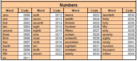
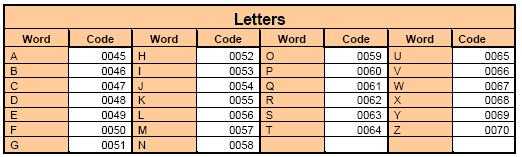
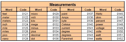
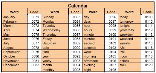
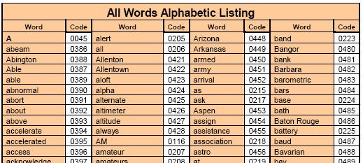
156 Advanced Programming Messages -- Vocabulary 156
157 Advanced Programming Messages Paging Single-Tone Page Messages Always version only, never interruptable Custom Tones and Duration Default and Custom Inter-Page Delay Default and Custom Message Level Two-Tone Sequential Page Messages Always version only, never interruptable Custom Tones and Duration Default and Custom Inter-Page Delay Default and Custom Message Level 5/6-Tone Page Messages Always version only, never interruptable Default and Custom Inter-Page Delay Default and Custom Message Level 157

158 Advanced Programming Messages Run-Time Variables Speech or CW of Controller Variables Clock and Calendar Data Hour and Minute 12- and 24-Hour Time Format AM/PM morning, afternoon, evening Day of Week Day of Month Cardinal or Ordinal Month Seconds Useful for testing clock accuracy Software Version Coming Soon! Analog Input Readings Readback of many datatypes 158 Note: Call Count is a leftover Autopatch variable that always reads zero.
159 Advanced Programming Receiver Timing COR/CTCSS Delay Programmable timers that filter narrow pulses on the COR and CTCSS logic inputs. Disabled by default. Reduces nuisance repeater key-ups due to noise. Flutter Filter The opposite of the COR/CTCSS Delay. Programmable timer that filters narrow dropouts of weak signals. Default is Disabled. Reduces the effects of picket fencing. Holds the audio path open to reduce audio dropouts. Minimizes Courtesy Beeps on weak 159 signals. Anti-Kerchunk Filter COR filter that removes brief user kerchunks. (NOBODY does THAT!) Default is Disabled. Key-up Delay specifies minimum keyup time. Default is 1.00 second. Re-Arm Delay specifies repeater idle time before the filter is re-armed. Default is 60 seconds. No-Hangtime Mode keys the repeater during the Key-Up Delay time, but eliminates the tail if unkey occurs before the delay time.
160 Advanced Programming Macros What s a Macro? A Macro is a list of controller commands or other macros that are executed in sequence. A Macro is assigned a unique name that is specified to cause execution of the sequence. Each macro is up to 200 digits long. Default is no macros defined. Directory and storage support 340 macros. Names are 1, 2, 3, or 4 DTMF digits. DTMF digits 0 thru 9 and A thru D. * and # cannot be used. Examples: 1* 40B* 789* 160 What are they good for? Speak the Date and Time Generate DTMF Pages Change which ports are linked Reset a Path Timeout Timer Speak a message when a Logic Input changes state. Perform custom timing sequences. Implement Rotating Identifier Messages Implement a Grandfather Clock Implement Top-of-the-Hour Meeting Announcements
161 Advanced Programming Macros Create Macro Command to allocate storage, define the name used to execute the macro, and store the first command. Added command must be valid. Name must be unique. Ex * Append To Macro Command to append additional commands to existing macro storage that will be executed in sequence. Ex * Execute Macro Type the name of the macro to execute Ex * Command Examples 7330> * OK 7330> * Error: Macro name already exists 7330> * Error: Macro name not found 7330> * OK 7330>1234* OK 7330> 161


162 Advanced Programming Event-Triggered Macros Allow Controller Events To Trigger Macros Assign Macro commands to configure the macro name to be executed at an event Many, many events defined Power-On Reset is commonly used. Logic Inputs useful for alarm inputs. PTT Active-to-Inactive used for Fan control. Ex. Set Power-On Reset Macro to * 162


163 Advanced Programming CTCSS Encoder CTCSS Encoder Control internal or external CTCSS Encoder Internal CTCSS Encoder Hardware Select from 65 subaudible tones Select Mode for when tone is enabled. Select Reverse Burst Option. 163
164 Advanced Programming CTCSS Encoder Chicken Burst Problem Most amateur radios don t respond to Reverse Burst. Turning the CTCSS Encoder off before Tx unkeys eliminates unkey squelch burst in user radio. Use Tx PTT Minimum Unkey Delay to implement Chicken Burst Works with all radios. Example Setup internal encoder Enable encoder on Tx Hz On whenever Tx is keyed Reverse Burst 180-Degree Support for Chicken Burst * ; set Tx1 mode, and reverse burst * ; set Tx1 frequency * ; set Tx1 Unkey Delay 750 ms 164

165 Advanced Programming Scheduler Setpoints Schedule Events Based On Time and Date Execute a macro based on combinations of month, day, day-of-week, hour, minute. Accepts wildcards to program recurring events Day Codes support special day matching Clock/Calendar provides accurate date/time Event stored in a Setpoint e.g. 2nd Tuesday of the month Ex., Speak Grandfather Clock macro 1234 every month, every day, every hour on the hour. Macro speaks time * * 165
166 Agenda Introduction Who is S-COM? The Basics Repeater Building Blocks What does a controller need to do? Common Terms Introducing the 7330 Wiring It Up Connectors, Jumpers, Pots Power Input Logic Signals Output Logic Signals Audio A-to-D Input Signals CTCSS Encoder Basic Programming Testing on the Bench Initializing the Controller S-COM Command Formats Security Data Types Introduction to the Manual Getting Started with Programming Commands Testing Your Results 166 Advanced Programming Ports and Paths More About Messages Receiver Timing Macros CTCSS Encoder Scheduler File Management Introducing SBOOT PC-Based Utilities S-COM Custom Audio Utility Other Controller Topics Digital Linking: IRLP, EchoLink, Allstar
167 File Management Introducing SBOOT The SBOOT Menu Manage your controller files Set the Clock/Calendar Update Firmware Load Speech Libraries Save/Restore Controller Configuration Configure the Serial Ports SCOM 7330 SBOOT V Controller Storage Management T - Show Time Tmmddyyhhmmssw - Set Date and Time (w=0=sunday) S - Save Controller Configuration R - Restore Controller Configuration E - Erase Files L - Load File from a PC to Flash U - Upload File from Flash to a PC D - Display Flash Directory P - Set Baudrate of Console Port N - Set Baudrate of Auxiliary Port W - Set Console Port Number B - Boot from Flash X - Reboot SBOOT from Flash H - Help Time : Battery: OK. SBOOT> 167
168 File Management Introducing SBOOT Flash Directory Displays Controller Information Display Filenames and Versions Firmware Files Configuration Files Speech Files Controller Information Model Number : 7330 Serial Number : Proto1 Manufactured DT: Formatted DT : Customer Name : Dave's Proto Firmware Files Location Name Version Date Type SYSTEM BootROM SBOOT 7330_SBoot /27/2014 Program MFG No File DIAG No File SCOM_A /27/2014 Program SCOM_B No File Configuration Files Location Name Version Date Type CONFIG_A W5JR /31/14 09:27 Configuration CONFIG_B No File CONFIG_C No File CONFIG_D No File Speech Files Location Name Version Date Type LIB SCOM Sp Lib Eng /8/2011 Speech Library CUSTOM No File 168
169 File Management Introducing SBOOT Erase Files Prepare for a firmware update Free configuration space Erase a File from Flash: Location Description 0 - SBOOT -- File Management Utility 1 - DIAG -- Diagnostics 2 - SCOM_A Repeater Controller 3 - LIB -- Speech Library 4 - CUSTOM -- Custom Audio Library 5 - CONFIG_A -- Configuration A 6 - CONFIG_B -- Configuration B 7 - CONFIG_C -- Configuration C 8 - CONFIG_D -- Configuration D Q - Return to Main Menu H - Redisplay these options Enter File Erase Option> Load a File to Flash from a PC: Load File from a PC to Flash Update Firmware Load a Custom Audio Library Load a Configuration File Location Description 0 - SBOOT -- File Management Utility 1 - DIAG -- Diagnostics 2 - SCOM_A Repeater Controller 3 - LIB -- Speech Library 4 - CUSTOM -- Custom Audio Library 5 - CONFIG_A -- Configuration A 6 - CONFIG_B -- Configuration B 7 - CONFIG_C -- Configuration C 8 - CONFIG_D -- Configuration D Q - Return to Main Menu H - Redisplay these options Enter File Load Option> 169
170 File Management Introducing SBOOT Save Controller Configuration Save the current controller configuration Restore Controller Configuration Restore the current controller configuration Upload File to a PC from Flash Upoad a Configuration File for storage or cloning. Save the Controller Configuration to a Flash File: Location Description 5 - CONFIG_A -- Configuration A 6 - CONFIG_B -- Configuration B 7 - CONFIG_C -- Configuration C 8 - CONFIG_D -- Configuration D Q - Return to Main Menu H - Redisplay these options Enter File Erase Option> Restore a Controller Configuration from a Flash File: Location Description 5 - CONFIG_A -- Configuration A 6 - CONFIG_B -- Configuration B 7 - CONFIG_C -- Configuration C 8 - CONFIG_D -- Configuration D Q - Return to Main Menu H - Redisplay these options Enter File Erase Option> Upload a File to a PC from Flash: Location Description 0 - SBOOT -- File Management Utility 1 - DIAG -- Diagnostics 2 - SCOM_A Repeater Controller 3 - LIB -- Speech Library 4 - CUSTOM -- Custom Audio Library 5 - CONFIG_A -- Configuration A 6 - CONFIG_B -- Configuration B 7 - CONFIG_C -- Configuration C 8 - CONFIG_D -- Configuration D Q - Return to Main Menu H - Redisplay these options Enter File Load Option> 170
171 Agenda Introduction Who is S-COM? The Basics Repeater Building Blocks What does a controller need to do? Common Terms Introducing the 7330 Wiring It Up Connectors, Jumpers, Pots Power Input Logic Signals Output Logic Signals Audio A-to-D Input Signals CTCSS Encoder Basic Programming Testing on the Bench Initializing the Controller S-COM Command Formats Security Data Types Introduction to the Manual Getting Started with Programming Commands Testing Your Results 171 Advanced Programming Ports and Paths More About Messages Receiver Timing Macros CTCSS Encoder Scheduler File Management Introducing SBOOT PC-Based Utilities S-COM Custom Audio Utility Other Controller Topics Digital Linking: IRLP, EchoLink, Allstar

172 PC-Based Utilities Custom Audio Add.wav Files to your Controller Use a program like Audacity or SoX to record or prepare custom audio. S-COM provides a utility to prepare the file for download to the controller. Your audio becomes Words in the controller that you can play just like the built-in vocabulary. Add up to 2000 new Words to the controller. Divide up 13 minutes of storage into as many or as few Words as you need. 172
CAT-260 Repeater Controller Computer Automation Technology, Inc
 CAT-260 Repeater Controller Computer Automation Technology, Inc 7378 W. Atlantic Blvd. #239 Margate, Florida 33063 Phone: (954) 978-6171 Fax: (561) 465-5891 Internet: http://www.catauto.com Table of Contents
CAT-700 Repeater Controller
 CAT-700 Repeater Controller Computer Automation Technology, Inc. 4631 N.W. 31st Avenue, Suite 142 Fort Lauderdale, Florida 33309 Phone: (954) 978-6171 Fax: (561) 488-2894 Internet: http://www.catauto.com
ICS REPEATER CONTROLLERS
 ICS REPEATER CONTROLLERS BASIC CONTROLLER USER MANUAL INTEGRATED CONTROL SYSTEMS 1076 North Juniper St. Coquille, OR 97423 Email support@ics-ctrl.com Website www.ics-ctrl.com Last updated 5/07/15 Basic
CAT-800 Repeater Controller Computer Automation Technology, Inc
 CAT-800 Repeater Controller Computer Automation Technology, Inc 7378 W. Atlantic Blvd. #239 Margate, Florida 33063 Phone: (954) 978-6171 Fax: (561) 465-5891 Internet: http://www.catauto.com Table of Contents
B & D Enterprises 1P repeater controller pg 1 INTRODUCTION:
 B & D Enterprises 1P repeater controller pg 1 INTRODUCTION: The 1P is a basic repeater controller. The controller uses low power devices and stores all commands and system status in non-volatile EE prom.
CAT-700B Repeater Controller Computer Automation Technology, Inc
 CAT-00B Repeater Controller Computer Automation Technology, Inc N.W. st Avenue, Suite Fort Lauderdale, Florida 0 Phone: () 8- Fax: () 88-8 Internet: http://www.catauto.com Table of Contents Chapter Page.
CONNECT SYSTEMS INCORPORATED 5321 Derry Ave., Suite B Agoura Hills, CA FLEX SERIES UNIVERSAL CONTROLLER
 CONNECT SYSTEMS INCORPORATED 5321 Derry Ave., Suite B Agoura Hills, CA 91301 Phone (805) 642-7184 Fax (805) 642-7271 FLEX SERIES UNIVERSAL CONTROLLER FLEX IIIA CTCSS COMMUNITY TONE PANEL User s Instruction
NHRC-7 User Guide. Software Version: User Guide Version: 2004-Dec-24
 NHRC-7 User Guide Software Version:. User Guide Version: 004-Dec-4 Copyright Notice Copyright 00, 004 by NHRC LLC This document contains proprietary information that is the confidential property of NHRC
NHRC-2.1 User Guide. Software Version: User Guide Version: 2012-Sep-15
 NHRC-. User Guide Software Version:.0 User Guide Version: 0-Sep-5 Copyright Notice Copyright 0 by NHRC LLC This document contains proprietary information that is the confidential property of NHRC LLC.
PR-1. Paging Tone Regenerator. Manual Revision: Covers Software Revisions: PR-1: 1.1 and higher. Covers Hardware Revisions: PR-1: 283B
 PR-1 Paging Tone Regenerator Manual Revision: 2008-01-14 Covers Software Revisions: PR-1: 1.1 and higher Covers Hardware Revisions: PR-1: 283B 1 SPECIFICATIONS Operating Voltage Operating Current Operating
RC-210 Repeater Controller Operations and Programming Manual
 Arcom Communications 24035 NE Butteville Rd Aurora, Oregon 97002 (503) 678-6182 arcom@ah6le.net http://www.ah6le.net/arcom/rc210/rc210.html RC-210 Repeater Controller Operations and Programming Manual
ICS REPEATER CONTROLLERS
 ICS REPEATER CONTROLLERS SINGLE M USER MANUAL INTEGRATED CONTROL SYSTEMS 1613 Bonnie Avenue Dixon, IL 61021 Voice 815-284-6963 Fax 815-288-0718 Website www.ics-ctrl.com Last updated 01/08/2005 Single M
Pion and Simon Electronics. PSE Repeater Controller User s Guide
 Pion and Simon Electronics PSE-508-3 Repeater Controller User s Guide Document Version 1.0 Revised November 21, 2011 Pion & Simon Electronics LLC PO Box 23651, Tigard, OR 97281 (503) 545-4732 www.pionsimon.com
CAT-300DXL Repeater Controller Computer Automation Technology, Inc
 CAT-300DXL Repeater Controller Computer Automation Technology, Inc 4631 N.W. 31st Avenue, Suite 142 Fort Lauderdale, Florida 33309 Phone: (954) 978-6171 Fax: (561) 488-2894 Internet: http://www.catauto.com
Mastr III P25 Base Station Transmitter Tune-up Procedure
 Mastr III P25 Base Station Transmitter Tune-up Procedure 1. Overview The Mastr III Base Station transmitter alignment is performed in several steps. First, the Transmit Synthesizer module is aligned to
CONNECT SYSTEMS INCORPORATED 1802 Eastman Ave., Suite 116 Ventura, Ca FLEX SERIES UNIVERSAL CONTROLLER
 CONNECT SYSTEMS INCORPORATED 1802 Eastman Ave., Suite 116 Ventura, Ca. 93003 Phone (805) 642-7184 Fax (805) 642-7271 FLEX SERIES UNIVERSAL CONTROLLER FLEX IIIA LTR CONTROLLER AND COMMUNITY TONE PANEL User
New Directions in Repeater Controllers: Presenting the S-COM 7000 Series
 New Directions in Repeater Controllers: Presenting the S-COM 7000 Series 1 INTRODUCTION Why does the world need another repeater controller? It s because our hobby is changing. No one will argue that amateur
RC-210 Repeater Controller Operations and Programming Manual
 Arcom Communications 24035 NE Butteville Rd Aurora, Oregon 97002 (503) 678-6182 arcom@ah6le.net http://www.ah6le.net/arcom/rc210.html RC-210 Repeater Controller Operations and Programming Manual Firmware
Technical Equipment Specification
 STATE OF CALIFORNIA Office of the State Chief Information Officer Public Safety Communications Division Technical Equipment Specification Equipment Type: Transmitter/Receiver Mobile Relay/Base/Control
Maintenance Manual. MTD SERIES 900 MHz, 10-WATT, DATA ONLY MOBILE RADIO. Mobile Communications LBI TABLE OF CONTENTS
 Mobile Communications MTD SERIES 900 MHz, 10-WATT, DATA ONLY MOBILE RADIO TABLE OF CONTENTS RF BOARD............................... LBI-38545 AUDIO BOARD............................ LBI-38546 LOGIC BOARD............................
G1SLE Mk2 Repeater Controller Programming.
 G1SLE Mk2 Repeater Controller Programming. The 89C55WD or equivalend microprocessor is supplied with G1SLE repeater controller software pre-loaded in flash memory. The various parameters such as callsign
Chapter 15: Serial Controlled (HF) Radio Support
 Radio Support") 15-1 Chapter 15: Serial Controlled (HF) Radio Support This section describes the controller's interface for serial controlled radios. Most such radios are for the HF bands, but some such as the FT-736
15-1 Chapter 15: Serial Controlled (HF) Radio Support This section describes the controller's interface for serial controlled radios. Most such radios are for the HF bands, but some such as the FT-736
MAINTENANCE MANUAL FOR CONVENTIONAL NETWORK INTERFACE
 C MAINTENANCE MANUAL FOR CONVENTIONAL NETWORK INTERFACE TABLE OF CONTENTS Page SPECIFICATIONS................................................ 1 INTRODUCTION.................................................
TECHNICAL INFORMATION BULLETIN
 TECHNICAL INFORMATION BULLETIN T/B No.: TIBFM 15-02 Rev A Revision date: JUNE24/08 Issue Date: JUNE18/08 TiL Model: TDFM-600/6000/7000 transceivers with Type I or Type II modules. TiL P/N: 011210-1,-2,-3,-4,-5
BTD-2. BTD-2 MOD-1272 Addendum
 BTD-2 Burst Tone Decoder BTD-2 MOD-1272 Addendum Motorola MDC-1200 ANI Mute Option Manual Revision: 2008-07-21 Covers Software Revisions: BTD-2: 1.0 & Higher Covers Hardware Revisions: UED-1: 283B 1 SPECIFICATIONS
MICROPROCESSOR REPEATER CONTROLLER
 5K MICROPROCESSOR REPEATER CONTROLLER Owner's Manual Software Version: V2.0 Manual Last Modified: 09-10-2002 S-COM, LLC P.O. Box 1546 LaPorte, CO 80535-1546 Phone: 970-416-6505 Fax: 970-419-3222 www.scomcontrollers.com
EDACS WALL MOUNT STATION. Maintenance Manual. Mobile Communications LBI-31838A TABLE OF CONTENTS
 A Mobile Communications EDACS WALL MOUNT STATION TABLE OF CONTENTS SYSTEM BOARD & REGULATOR BOARD.......... LBI-31892 KEY/DISPLAY BOARD MAINTENANCE MANUAL.... LBI-31940 Maintenance Manual Printed in U.S.A.
Interfacing the Yaesu DR 1X
 Interfacing the Yaesu DR 1X With The S Com 7330 Repeater Controller For a Feature Rich Digital and Analog Experience! An Install Guide by Justin Reed, NV8Q As Implemented on the K Link Network http://ks0lnk.net
TABLE OF CONTENTS. Keypad Programming Manual 1
 TABLE OF CONTENTS How To Program Radios...2 Keypad Programming...2 A. Navigation...3 1. Group Parameters (CH 00)...4 2. Channel Parameters (CH 01 - CH20)...4 3. Global Parameters (GRP 00)...5 B. Group
ANI-F-VX. Multi-Format ANI Encoder. Portables: VX-350, VX-410, VX-420, VX-450-VX-460, VX-600, VX-800, VX-820, VX-900, VX-920
 ANI-F-VX Multi-Format ANI Encoder Manual Revision: 2011-04-06 This manual & product supports the following radios: Portables: VX-350, VX-410, VX-420, VX-450-VX-460, VX-600, VX-800, VX-820, VX-900, VX-920
LBI-31564A. Mobile Communications. DELTA - SX MHz RADIO COMBINATIONS (NEGATIVE GROUND ONLY) Maintenance Manual
 Maintenance Manual") A Mobile Communications DELTA - SX 136-174 MHz RADIO COMBINATIONS (NEGATIVE GROUND ONLY) Maintenance Manual TABLE OF CONTENTS MILITARY AND SYSTEM SPECIFICATIONS................................. 2-3 COMBINATION
A Mobile Communications DELTA - SX 136-174 MHz RADIO COMBINATIONS (NEGATIVE GROUND ONLY) Maintenance Manual TABLE OF CONTENTS MILITARY AND SYSTEM SPECIFICATIONS................................. 2-3 COMBINATION
CONNECT SYSTEMS INCORPORATED 1802 Eastman Ave., Suite 116 Ventura, Ca FLEX SERIES II UNIVERSAL CONTROLLER
 CONNECT SYSTEMS INCORPORATED 1802 Eastman Ave., Suite 116 Ventura, Ca. 93003 Phone (805) 642-7184 Fax (805) 642-7271 FLEX SERIES II UNIVERSAL CONTROLLER MULTIMODE INTERCONNECT AND EIA TONE REMOTE E&M VERSION
ANI-F-VX. Multi-Format ANI Encoder. Manual Revision: This manual & product supports the following radios:
 ANI-F-VX Multi-Format ANI Encoder Manual Revision: 2009-05-05 This manual & product supports the following radios: Portables: VX-350, VX-410, VX-420, VX-600, VX-800, VX-820, VX-900, VX-920 Mobiles: VX-2100,
APPENDIX A PARAMETER DESCRIPTIONS
 APPENDIX A PARAMETER DESCRIPTIONS CONTENTS Page INTRODUCTION A.5 CHANNEL PARAMETERS #101 -#102 Channel Frequencies A.5 #103 Microcomputer Clock Offset A.6 #104 Transmitter Power A.6 #105 Squelch A.6 #106
Reference for UV-5R Menus by Jim Unroe - KC9HI 2-April-2014
 Long Name / Description / / Notes / 0 SQL Carrier Squelch Mutes the speaker of the transceiver in the absence of a strong signal. VHF squelch is either OFF or ON. UHF squelch is either OFF or one of 9
PC Tune PC Tune Test Procedures for 5100 Series Portable Radios
 PC Tune PC Tune Test Procedures for 5100 Series Portable Radios Part Number 002-9998-6513014 August 2008 Copyright 2006, 2007, 2008 by EFJohnson Technologies The EFJohnson Technologies logo, PC Configure,
Installation Manual Console Integration System
 Installation Manual Console Integration System Table of Contents Kit Contents... 2 Overview... 3 Installation Instructions... 3 Typical Installation Wiring Diagram... 4 Configuring the Network Bridge...
LBI-31807D. Mobile Communications MASTR II REPEATER CONTROL PANEL 19B234871P1. Maintenance Manual. Printed in U.S.A.
 D Mobile Communications MASTR II REPEATER CONTROL PANEL 19B234871P1 Maintenance Manual Printed in U.S.A. This page intentionally left blank 13 PARTS LIST 12 PARTS LIST LBI-31807 11 PARTS LIST 10 SCHEMATIC
Repeaters and Linking
 Presented by Rob Ewert VE1KS \ Introduction / My Background Repeaters What are they? Why do we need them? How do they work? How are they controlled What kinds are there? Where are they? What do I need
CONNECT SYSTEMS INCORPORATED 1802 Eastman Ave., Suite 116 Ventura, Ca FLEX III UNIVERSAL CONTROLLER
 CONNECT SYSTEMS INCORPORATED 1802 Eastman Ave., Suite 116 Ventura, Ca. 93003 Phone (805) 642-7184 Fax (805) 642-7271 FLEX III UNIVERSAL CONTROLLER INTERCONNECT DISPACH SYSTEM AA User s Instruction Manual
WJ9J Repeater Accessory Board. Version
 WJ9J Repeater Accessory Board Version 2015-05-18 1 This manual Copyright 2013-2017 by Andy Zorca, WJ9J, All Rights Reserved. Hardware Notice The code contained in the 16F88 Microchip device is copy protected.
WJ9J DTMF and Remote Base Controller. Version
 WJ9J DTMF and Remote Base Controller Version 2016-12-19 1 This manual Copyright 2012 by Andy Zorca, WJ9J, All Rights Reserved. Hardware Notice The code contained in the 16F628A or 16F88 Microchip device
ComLink BCR-40U/50V/220 Owner s Manual. By BridgeCom Systems, Inc.
 ComLink BCR-40U/50V/220 Owner s Manual By BridgeCom Systems, Inc. Copyright 2015 BY Bridge Embedded Systems, Inc Version 1.7, July 2015 All rights reserved. Printed in the United States of America. LTR
RMV25 / RMV50 RMU25 / RMU45
 RMV25 / RMV50 RMU25 / RMU45 Owner's Manual TABLE OF CONTENTS INTRODUCTION... 3 FCC Requirements... 3 SAFETY WARNING INFORMATION... 3 CONTROLS and INDICATORS... 5 FRONT PANEL... 5 LCD Icons and Indicators...
FM Audio/Squelch Board by Steve Dold, W6KCS w6kcs (at) stevedold (dot) com
 stevedold (dot) com") FM Audio/Squelch Board by Steve Dold, W6KCS w6kcs at stevedold dot com Board hardware version 7-8 Firmware version 7.x This board connects to an FM receiver's discriminator/detector and provides squelched,
FM Audio/Squelch Board by Steve Dold, W6KCS w6kcs at stevedold dot com Board hardware version 7-8 Firmware version 7.x This board connects to an FM receiver's discriminator/detector and provides squelched,
Maintenance Manual ERICSSONZ LBI-31552E
 E Maintenance Manual TONE REMOTE CONTROL BOARD 19A704686P4 (1-Frequency Transmit Receive with Channel Guard) 19A704686P6 (4-Frequency Transmit Receive with Channel Guard) ERICSSONZ Ericsson Inc. Private
CAD-MF. PC-Based Multi-Format ANI & Emergency ANI Display Decoder. Manual Revision: Covers Firmware Revisions: CAD-MF: 1.
 CAD-MF PC-Based Multi-Format ANI & Emergency ANI Display Decoder Manual Revision: 2010-05-25 Covers Firmware Revisions: CAD-MF: 1.0 & Higher Covers Software Revisions: CAD: 3.21 & Higher Covers Hardware
5096 FIRMWARE ENHANCEMENTS
 Document Number A100745 Version No.: 4.4.1 Effective Date: January 30, 2006 Initial Release: September 19, 2005 1. Fixed display of logged memory date and time broken in version 4.3. 2. Allow time samples
BeeLine TX User s Guide V1.1c 4/25/2005
 BeeLine TX User s Guide V1.1c 4/25/2005 1 Important Battery Information The BeeLine Transmitter is designed to operate off of a single cell lithium polymer battery. Other battery sources may be used, but
SNV-12 Voter Quick Reference Help Sheets
 Chassis, Power Supply, and CIM Module SNV-12 Configuration Settings and Adjustments (0=Off, 1=On) Chassis Rear Panel: Designator Factory Setting Switch Choices AC Line Voltage Rear Panel AC Input Module
Portable Repeater Controller. Instruction Manual for firmware version 1.0
 Portable Repeater Controller Instruction Manual for firmware version 1.0 1. Table of Contents 1. TABLE OF CONTENTS... 2 2. INTRODUCTION... 3 2.1 OVERALL DESCRIPTION... 3 2.2 WARNINGS... 4 2.3 CONFIGURATION
TACT TA-4800 RACK MOUNT VERSION USER HANDBOOK. Issue 2, Dec, 2009 ACMA SUPPLIER S CODE N468 NEW ZEALAND TELEPERMIT PTC 210/96/003
 TACT TA-4800 MAN ALONE PERSONAL SAFETY ALARM RADIO / TELEPHONE INTERCONNECT RACK MOUNT VERSION USER HANDBOOK Issue 2, Dec, 2009 ACMA SUPPLIER S CODE N468 NEW ZEALAND TELEPERMIT PTC 210/96/003 DESIGNED
DJ-MD5 PC Software Guidance
 DJ-MD5 PC Software Guidance Ver, 1.00 2018/08/16 1 Appendix I Public... 4 1. Channel... 4 1 Frequency, call type, power... 4 2 Digital Channel Setting... 5 3 Analog Channel Setting... 6 2. Zone... 7 3.
JEM Radio II Operation Guide. Manual P/N M Victor Place Colorado Springs, Colorado
 JEM Radio II Manual P/N M09999-999 2115 Victor Place Colorado Springs, Colorado 80915 800.284.0399 www.jemcom.com Table of Contents Display... 3 Channel Entry... 4 Shortcuts... 4 Text Messages... 4 Buttons...
TDM-1 TRANSPARENT OR ADDRESSABLE RADIO DATA MODEM INSTRUCTION MANUAL
 TDM-1 TRANSPARENT OR ADDRESSABLE RADIO DATA MODEM INSTRUCTION MANUAL Features 1200 baud modem for point to point to multi-point communications Simplex or full-duplex operation 63 character flow control
Technical Application Note #3
 CRC CACTUS Radio Club, Inc. This Technical Application Note describes alignment procedure for a Palomar Telecom RBC- 700 series controller. The following instructions are individually described: Initial
BFoxCon Manual. Version 0.2 October 30, 2017
 Overview The Byonics BFoxCon is a radio controller board designed to pair with a Baofeng UV-5R to create a transceiver for hidden transmitter hunts, also called T-hunts, foxhunts, and ARDF. It mounts on
Hamtronix. Repeater Controller. Elektra Instruction Manual. Software V2.13 Hardware Revision I
 Repeater Controller Elektra 2000 Instruction Manual Software V2.13 Hardware Revision I Technical Support... 02 Precautions... 02 Warranty... 02 Software Update... 02 CONNECTORS CN1 - RPT... 03 CN2 - LINK...
INDEX...2 INTRODUCTION...3 IMPORTANT NOTES...3 INSTALLING THE SOFTWARE...3 ST-965 PROGRAMMING SOFTWARE...6
 ST-965 VX/D SMARTRUNK II & SMARTRUNK XPRESS Logic board Programming Software 2.9e User s Guide Revision R2.9 10/10/2008 INDEX INDEX...2 INTRODUCTION...3 IMPORTANT NOTES...3 INSTALLING THE SOFTWARE...3
PSE-702 Dual Channel Repeater Controller Operator's Guide
 PSE-702 Dual Channel Repeater Controller Operator's Guide Version 2.8, November 19, 2013 Conforms to Firmware Version 3.2.2 Copyright 2012-2013 Pion and Simon Electronics LLC. All rights reserved. THIS
T70 / T150 Transmitter Operation and Maintenance Manual
 Eclipse Series RF Technology rfinfo@rftechnology.com.au May, 2005 T70 / T150 Transmitter Operation and Maintenance Manual This manual is produced by RF Technology Pty Ltd 10/8 Leighton Place, Hornsby NSW
MASTR II AUXILIARY RECEIVER 19D417546G7 & G8 & ANTENNA MATCHING UNITS 19C321150G1-G2. Maintenance Manual LBI-30766L. Mobile Communications
 L Mobile Communications MASTR II AUXILIARY RECEIVER 19D417546G7 & G8 & ANTENNA MATCHING UNITS 19C321150G1-G2 Printed in U.S.A Maintenance Manual TABLE OF CONTENTS Page SPECIFICATIONS.....................................................
MAINTENANCE MANUAL AUDIO MATRIX BOARD P29/
 MAINTENANCE MANUAL AUDIO MATRIX BOARD P29/5000056000 TABLE OF CONTENTS Page DESCRIPTION................................................ Front Cover CIRCUIT ANALYSIS.............................................
SUBELEMENT T4. Amateur radio practices and station set up. 2 Exam Questions - 2 Groups
 SUBELEMENT T4 Amateur radio practices and station set up 2 Exam Questions - 2 Groups 1 T4A Station setup: connecting microphones; reducing unwanted emissions; power source; connecting a computer; RF grounding;
DPT-1 & DPT-2. Dial Access Paging Terminal. Manual Revision: Covers Firmware Revisions: DPT: 1.57 and higher
 DPT-1 & DPT-2 Dial Access Paging Terminal Manual Revision: 2008-07-22 Covers Firmware Revisions: DPT: 1.57 and higher Covers Hardware Revisions: DPT-1: E and higher DPT-2: F and higher 1 TABLE OF CONTENTS
Testing Motorola P25 Conventional Radios Using the R8000 Communications System Analyzer
 Testing Motorola P25 Conventional Radios Using the R8000 Communications System Analyzer Page 1 of 24 Motorola CPS and Tuner Software Motorola provides a CD containing software programming facilities for
Cat. No OWNER S MANUAL. HTX-212 Two-Meter Mobile Transceiver. Please read before using this transceiver.
 19-1125.fm Page 1 Tuesday, August 3, 1999 9:47 AM Cat. No. 19-1125 OWNER S MANUAL HTX-212 Two-Meter Mobile Transceiver Please read before using this transceiver. 19-1125.fm Page 2 Tuesday, August 3, 1999
MicroFox2 Manual. Version 0.5 August 28, 2017
 Overview The Byonics MicroFox2 (MF2) is a small, 500mW, frequency agile 2-meter transceiver designed for hidden transmitter hunts, also called T-hunts, foxhunts, and ARDF. It is based on the Byonics MicroFox-PicCon,
SR3400 Base Station Module Configuration and Use Series-2 Cards Only
 SR3400 Base Station Module Configuration and Use Series-2 Cards Only A.W. Communication Systems Ltd Crook Barn, The Crook Rowel Town, Carlisle Cumbria Telephone (44) 1697-748777 Fax (44) 1697-748778 www.toneremote.com
MABEL, PiTone and Allstar for the Yaesu Fusion DR-1X Repeater
 MABEL, PiTone and Allstar for the Yaesu Fusion DR-1X Repeater MABEL is a program designed to run on a Raspberry Pi 3 (rpi) in conjunction with Allstar/app-rpt controlling a Yaesu Fusion DR-1X repeater.
Receiver Adjustments
 ! -8-4!5 This Section details procedures for tuning and adjustment of T2000 series II radios. This is normally only required during product manufacture or after major servicing. The following topics are
Technical Application Note #4
 CRC CACTUS Radio Club, Inc. This Technical Application Note describes the modifications that need to be incorporated into a Link Communications RLC series controller to achieve near Cactus Standard Audio
CAT-200B Repeater Controller Computer Automation Technology, Inc.
 CAT-200B Repeater Controller Computer Automation Technology, Inc. 4631 N.W. 31st Avenue, Suite 142 Fort Lauderdale, Florida 33309 Phone: (954) 978-6171 Fax: (561) 488-2894 Internet: http://www.catauto.com
AT-D868UV CodePlug Programming Guide
 INTRODUCTION The AnyTone D868UV radio is a VHF and UHF radio with both Digital DMR (Tier I and II) and Analog capabilities. It offers a total of 4,000 channels (Analog and Digital) and up to 130,000 contacts,
IC-400pro - RADIOAFICION.COM
 PROCEDURES IC-400pro - 5- PREPARATION When you adjust the contents on pages 5-5 and 5-6, SOFT- WARE, the optional CS-400PRO ADJ SOFTWARE (Rev..0 or later), *OPC- JIG CABLE (modified OPC- CLONING CABLE;
ATP-5189 Programming Software for the Anytone AT-5189
 for the Anytone AT-5189 Memory Types Memories Limit Memories VFO Receive Frequency Transmit Frequency Offset Frequency Offset Direction Channel Spacing Name Tone Mode CTCSS Rx CTCSS DCS Memory Channel
RACK MOUNT REPEATER VXR Vertex Standard LMR, Inc. VXR-9000 FM REPEATER OPERATING MANUAL
 RACK MOUNT REPEATER VXR-9000 OPERATING MANUAL Vertex Standard LMR, Inc. INTRODUCTION The VXR-9000 is commercial-grade 50-watt FM repeater designed to provide reliable two-way full-duplex communications
ANI-F. Multi-Format ANI Encoder. Manual Revision: Covers Software Revisions: ANI-F: 1.2 and higher
 ANI-F Multi-Format ANI Encoder Manual Revision: 0-0-9 Covers Software Revisions: ANI-F:. and higher SPECIFICATIONS Operating Voltage +5.5-5 VDC Operating Current.6 ma Operating Temperature -0 - +60 C Frequency
EVDP610 IXDP610 Digital PWM Controller IC Evaluation Board
 IXDP610 Digital PWM Controller IC Evaluation Board General Description The IXDP610 Digital Pulse Width Modulator (DPWM) is a programmable CMOS LSI device, which accepts digital pulse width data from a
Micro Fox PicCon Manual
 Micro Fox PicCon Manual Version 0.61 The Micro Fox PicCon (MF PC) is a 700mW fox hunting/hidden transmitter hunt transceiver. It can be configured and remotely controlled via DTMF tones, and also be configured
MobileRadio. Owner'sManual
 EMH MobileRadio Owner'sManual TABLE OF CONTENTS Introduction... 1 Basic Operation... 2 Code Guard Operation... 3 EMH Radio Controls... 4 Button Functions... 4 Built-in Features... 7 Keypad Microphone Operation...
Basic Transceiver tests with the 8800S
 The most important thing we build is trust ADVANCED ELECTRONIC SOLUTIONS AVIATION SERVICES COMMUNICATIONS AND CONNECTIVITY MISSION SYSTEMS Basic Transceiver tests with the 8800S Basic Interconnects Interconnect
ST600 TRANSMITTER OPERATING INSTRUCTIONS
 ST600 TRANSMITTER OPERATING INSTRUCTIONS 1892 1273 These operating instructions are intended to provide the user with sufficient information to install and operate the unit correctly. The Wood and Douglas
MAINTENANCE MANUAL AUDIO AMPLIFIER BOARD 19D904025G1 (MDR) AUDIO AMPLIFIER BOARD 19D904025G2 (MDX)
 AUDIO AMPLIFIER BOARD 19D904025G2 (MDX)") A MAINTENANCE MANUAL AUDIO AMPLIFIER BOARD 19D904025G1 (MDR) AUDIO AMPLIFIER BOARD 19D904025G2 (MDX) TABLE OF CONTENTS DESCRIPTION............................................... Page Front Cover CIRCUIT
A MAINTENANCE MANUAL AUDIO AMPLIFIER BOARD 19D904025G1 (MDR) AUDIO AMPLIFIER BOARD 19D904025G2 (MDX) TABLE OF CONTENTS DESCRIPTION............................................... Page Front Cover CIRCUIT
Programming Parameter Guide
 Secure Wireless Microphone ELITE PRO Programming Parameter Guide rev:1 How to use Programmer: Start Programming application Runs On PC or Mac running Windows 7/10. To put Handset into programming mode,
Rack Mount Repeater VXR-9000E. Operating Manual. Vertex Standard LMR, Inc.
 Rack Mount Repeater VXR-9000E Operating Manual Vertex Standard LMR, Inc. Introduction The VXR-9000E is commercial-grade 25-watt FM repeater designed to provide reliable two-way full-duplex communications
WCS-D5100 Programming Software for the Icom ID-5100 Data
 WCS-D5100 Programming Software for the Icom ID-5100 Data Memory Types (left to right) Memories Limit Memories DR Memories Call Channels GPS Memories Receive Frequency Transmit Frequency Offset Frequency
Programming. Advanced Features
 Programming 4 Advanced Features Some of the MaxTrac models have the ability to be programmed for advanced features. These features include Channel Scan, Handset Muting, Expanded Accessory Connector, MDC-1200,
MODEL FVP-44. Setup & Programming Manual
 MODEL FVP-44 Rolling Code Encryption board for VX-450 / VX-4500 / VX-4600 VERTEX/STANDARD RADIOS Setup & Programming Manual Installation: Running the installation program, CimarronQuikWareSetupFVP44.EXE,
OPERATOR S MANUAL KYODO WEST MODEL KG506 FULL-DUPLEX MOBILE. Preliminary
 OPERATOR S MANUAL KYODO WEST MODEL KG506 FULL-DUPLEX MOBILE Preliminary 1.0 INTRODUCTION Thank you for purchasing the KYODO WEST MODEL KG506 Full-Duplex Mobile Radio. This manual contains information to
ANI-F-KW1. Multi-Format ANI Encoder For Kenwood Radios. Manual Revision: Covers Software Revisions: ANI-F: 1.
 ANI-F-KW1 Multi-Format ANI Encoder For Kenwood Radios Manual Revision: 2009-02-04 Covers Software Revisions: ANI-F: 1.2 and higher This manual & product supports the following radios: Portable: TK-2180/3180
Programming Parameters - Feature Comparison : Rev 1
 Secure Wireless Microphone ELITE PRO CLASSIC Programming Parameters - Feature Comparison : Rev 1 How to use Programmer: Start Programming application Runs On PC or Mac running Windows 7/8. To put Handset
Microphone audio, from the MFJ-1278B to your transmitter. Ground, audio and PTT common. Push-to-talk, to allow the MFJ-1278B to key your transmitter.
 Computer interfacing, covered in the previous chapter, is only half the interfacing task. The other half is connecting your MFJ-1278B to your radios. MFJ-1278B Radio Ports Interfacing the MFJ-1278B to
AT-5888UV Programming Software for the AnyTone AT-5888UV
 AT-5888UV Programming Software for the AnyTone AT-5888UV Memory Channel Functions Memory Types Memories Limit Memories Hyper Memory 1 Hyper Memory 2 Receive Frequency Transmit Frequency Offset Frequency
WIRES-X Portable Digital Node Function. Instruction Manual
 Wide-Coverage Internet Repeater Enhancement System WIRES-X Portable Digital Node Function Instruction Manual Please read this Instruction Manual carefully for appropriate procedure. Preparation Procedure
TECHNICAL NOTES MT-4 Radio Systems TN182 Battery Level Reporting and Remote P25 Test Tone
 Battery Level Reporting is a method of activating a repeater remotely to have it transmit a signal that reports the battery voltage level over RF. The Remote P25 Test Tone is a remotely activated Standard
The LZA2027 Tone Termination Panel Instruction and Programming Manual
 The LZA2027 Tone Termination Panel Instruction and Programming Manual BK Radio 7100 Technology Drive West Melbourne, FL 32904 Phone: (800) 648-0947 Fax: (321) 984-0434 www.relm.com 0300-30944-900 Rev.
ATP-588 Programming Software for the Anytone AT-588
 for the Anytone AT-588 Memory Channel Functions Memory Types Memories Limit Memories VFO Receive Frequency Transmit Frequency Offset Frequency Offset Direction Channel Spacing Name Tone Mode CTCSS Rx CTCSS
GSM-4 (program version 4.02)
") COMMUNICATION MODULE GSM-4 (program version 4.02) OPERATING INSTRUCTION GDAŃSK, POLAND gsm4_e 11/03 WARNING For safety reasons, the module should only be installed by qualified personnel. In order to avoid
COMMUNICATION MODULE GSM-4 (program version 4.02) OPERATING INSTRUCTION GDAŃSK, POLAND gsm4_e 11/03 WARNING For safety reasons, the module should only be installed by qualified personnel. In order to avoid
MODEL CIM-2000 DUALFORMAT ANI ENCODER/DECODER
 MODEL CIM-2000 DUALFORMAT ANI ENCODER/DECODER GE Star AND MDC-1200 ENCODER/DECODER Instruction Manual Manual Number 05 40 2000 Rev 080118 2005 2007 Cimarron Technologies Corp., Escondido, CA, USA. All