GAIN COMPARISON MEASUREMENTS IN SPHERICAL NEAR-FIELD SCANNING
|
|
|
- Alberta Bond
- 6 years ago
- Views:
Transcription
1 GAIN COMPARISON MEASUREMENTS IN SPHERICAL NEAR-FIELD SCANNING ABSTRACT by Doren W. Hess and John R. Jones Scientific-Atlanta, Inc. A set of near-field measurements has been performed by combining the methods of non-probe-corrected spherical near-field scanning and gain standard substitution. In this paper we describe the technique used and report on the results obtained for a particular 24 inch 13 GHz paraboloidal dish. We demonstrate that the gain comparison measurement used with spherical near-field scanning gives results in excellent agreement with gain comparison used with compact range measurement. Lastly we demonstrate a novel utilization of near-field scanning which permits a gain comparison measurement with a single spherical scan. INTRODUCTION Conventionally, near-field scanning gain measurements have been performed by range insertion loss measurements treating the test antenna and probe antenna pair as a two-port. Particularly for the case of planar near-field scanning this has been found to be both practical and accurate. More recently interest has been expressed in making near-field scanning gain measurements by substitution - i.e., comparison to a standard. This paper describes the results of a trial with such a comparison procedure and demonstrates the reliability of the method, by showing that the results are in close agreement with compact range results. SINGLE MODEL FOR FAR-FIELD AND NEAR-FIELD COMPARISON MEASUREMENTS Disregarding the significant details of polarization and mismatch correction, one can idealize the usual far-field gain comparison method as a simple power level comparison between two identically illuminated receiving antennas - one an antenna of unknown gain (or more properly, effective area) and the ether a gain standard whose gain is assumed known. It is easiest also to take the case of pure linear polarization for illustration. Under plane wave illumination conditions let G AUT = gain of the unknown antenna under test G STD = known gain of the standard P AUT FF = P STD FF = power level measured at the port of the antenna under test power level measured at the port of the gain standard antenna Recall that the result of the measurement is given by the far-field comparison formula: In logarithmic form, this is:
2 (This equation can be applied directly only to the case of linear polarization in which a partial gain measurement of one polarization alone suffices to characterize the result.) The measurement procedure calls simply for making a comparison of signal levels P AUT FF and P STD FF for the test antenna and the standard. In making a far-field gain comparison measurement one must always be satisfied with only an approximation to uniform plane wave illumination. In any actual far-field measurement the wavefront is somewhat spherically curved due to the finite distance of the source antenna away from the test zone. This wavefront curvature results in a small amplitude error in the received signal level. Testing in the near-field region of an antenna means the amplitude error due to the finite range length is so large that it cannot be neglected and grouped with other error contributions. In performing a gain comparison measurement in the near field, one must correct for phase curvature of the illuminating wavefront with data obtained from scanning. Thus near-field gain comparison measurements are similar to far-field measurements, but with the addition of near-field scanning. In the near field measurement, near-field patterns are measured and farfield patterns are computed for both the AUT and the gain standard. The difference in amplitude between the near-field pattern and the far-field pattern in the direction of interest for each antenna is included in the gain calculation formula. Define a near-field to far-field power ratio, K ANTENNA, NFFF for each antenna as follows: Where: = normalized magnitude of the E-field for the antenna at the far-field distance' in -the direction of known gain for the gain standard or in the direction for which the gain is desired for the AUT, and = normalized E-field magnitude at the near-field distance in the same direction. The gain comparison formula can be rewritten to read: or for the near-field case. The three terms in the near-field gain comparison equation correspond to the three measurements required. A near-field power level comparison measurement P AUT NF / P STD NF, and two range length correction factors P AUT FF / P AUT NF, P STD FF / P STD FF from the near-field scanning and transform operations. Thus the simplified measurement procedure calls for a comparison of signal levels P AUT NF, P STD NF under identical near-field illumination and for two scanning measurements of the test antenna and gain standard followed by two near-field to far-field transforms. Note that the gain comparison calculation formula reduce to the far-field formula as the range length correction factors approach unity. This simple gain comparison formula is all that we have used in the non-probe-corrected spherical near-
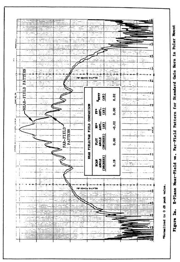
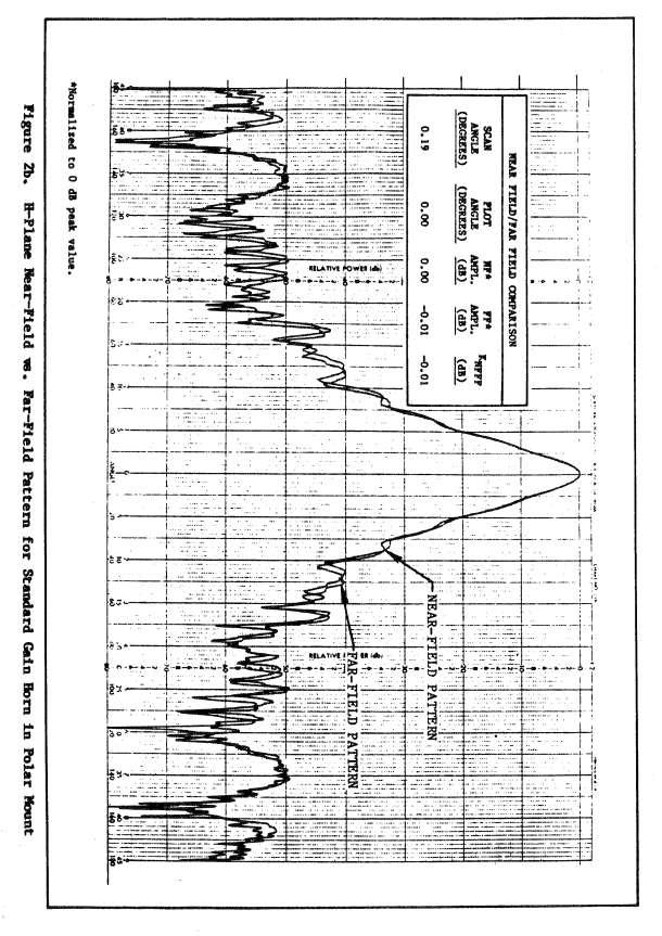
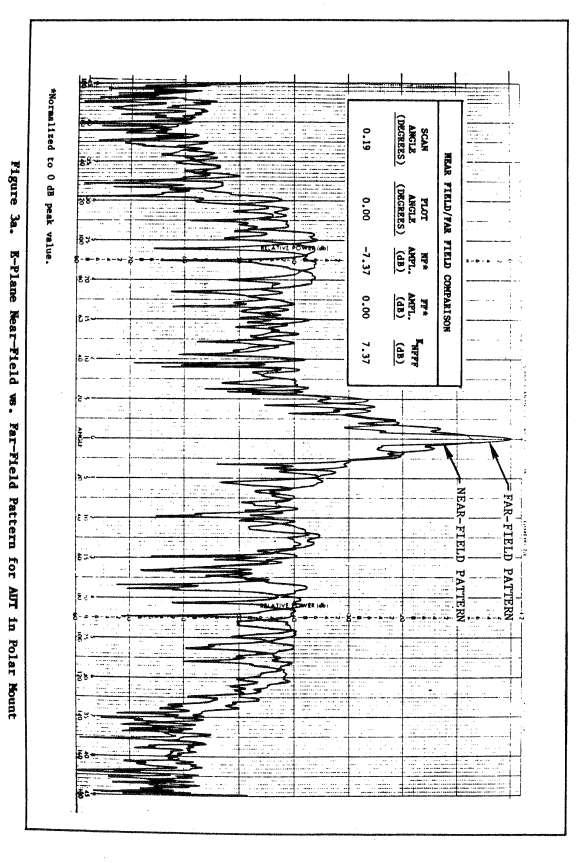
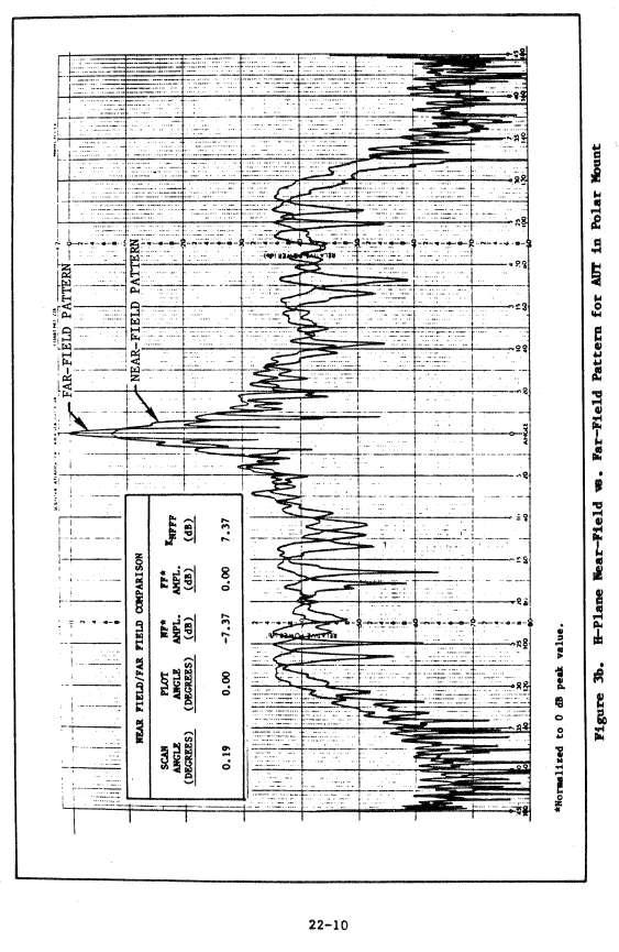
3 field gain comparison method reported here. It does not account for impedance mismatch, polarization correction or probe pattern illumination correction. Nevertheless it yields respectable results within its domain of validity - i.e., for well-matched linearly polarized antennas. BASIC NEAR-FIELD GAIN COMPARISON TECHNIQUES A schematic diagram of the spherical near-field range configuration is shown in Figure 1. The axis configuration used was roll-over-azimuth with the main beam of the test antenna along the roll axis. The instruments shown are part of a Scientific-Atlanta Model 2022A Antenna Analyzer. The standard gain horn was measured using near-field scanning and the results transformed to the far field. Similarly the antenna under test was measured and the data transformed. The test antenna was a 24 inch diameter paraboloidal reflector antenna operated at 13.0 GHz, the standard gain horn was a Scientific-Atlanta Model pyramidal horn. The near-field to far-field transform was performed using the standard software package available with the 2022A analyzer. Care was taken to align the peak of the gain standard pattern with the peak of the test antenna pattern. In Figures 2 and 3 we show the results of near-field scanning and the near-field to far-field transform. Figure 2 shows both principal planes for the standard gain horn and Figure 3 both principal planes for a 2- foot dish used throughout as the AUT. Inset in both figures are listings of the data from which the plots were generated. As Figure 2 indicates, the location (angular coordinates) and magnitude of the near-field and far-field peaks are the same for the standard gain horn. This data was acquired with a range length of cm which is about 3D 2 / λ - greater than the usual far-field criterion. Even so, the near-field and far-field patterns are different. For the standard gain horn as shown in Figure 2, K SGH,NFFF = 1. As shown in Figure 3, the far-field peak for the AUT is larger in magnitude than the near-field level in this direction. For the AUT, K AUT,NFFF = 7.37 db = Note that in this case the direction of the near-field peak is the same as that of the far-field peak. The signal power levels of the ports of the test antenna and the gain standard were compared as the gain horn was dismounted from the test positioner and the test antenna put in place. The near-field signal level comparison measurement is illustrated in Figure 4. (As in the far-field gain comparison measurement, mismatch error produces the largest uncertainty in this measurement.) A Scientific-Atlanta Model 14-5 mixer with a 20 db matching pad was used as a detector for this measurement. The measured difference in power level between the terminals of the AUT and of the gain standard was 2.73 db or a factor of Using the last equation for the near-field gain comparison formula we get G AUT = 2,440 = db. The gain of the standard gain horn was db.
4
5
6
7
8
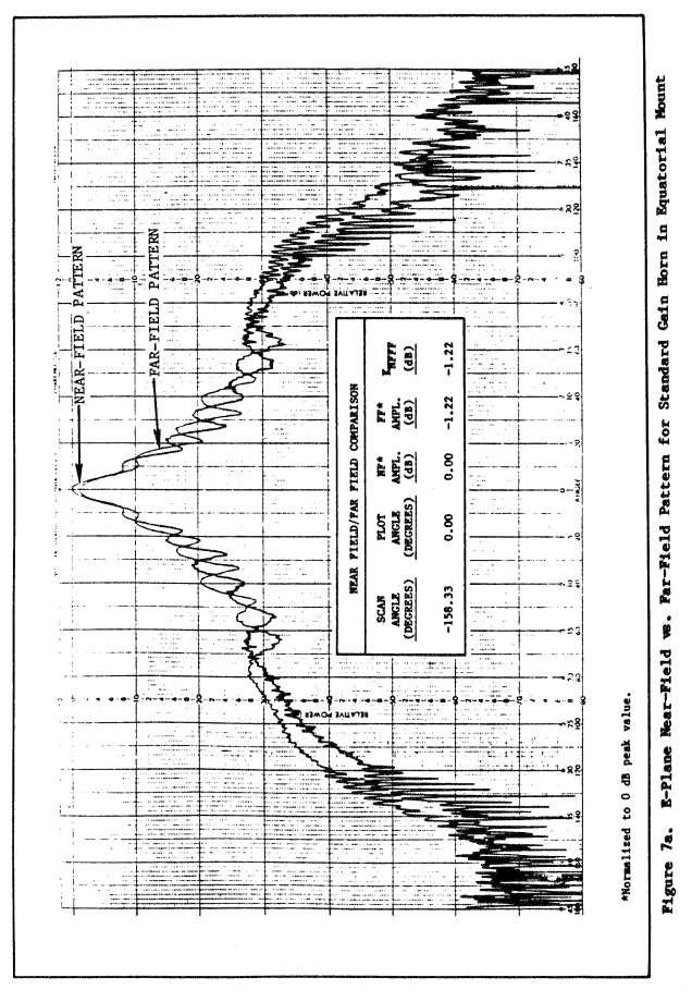
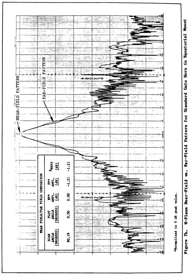
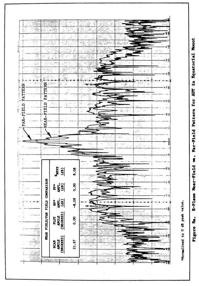
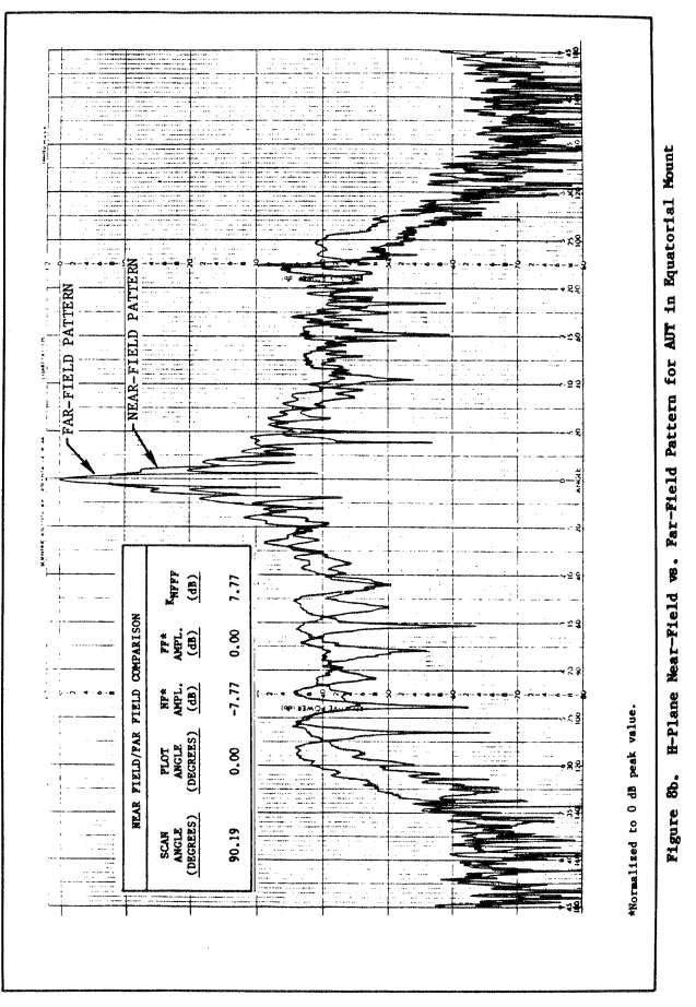
9 POLAR VERSUS EQUATORIAL MOUNTING All of the above measurements were made with the AUT and the gain standard mounted in polar configuration. That is, each antenna was mounted so that its main beam was centered on the north pole of the measurement sphere. We performed the measurements described above with the antennas in equatorial mount also, and some practical simplifications were achieved. Figure 5 illustrates the geometry of polar and equatorial mounting configurations and Figure 6 illustrates schematically the measurement setup used. Note that the roll axis of the test positioner resembles the switch axis setup commonly used for far-field gain comparison measurements. Figures 7 and 8 show measured near-field and calculated far-field patterns for both principal planes of each antenna in the mounting configuration of Figure 6. From Figure 7 we note that K STD, NFFF = db =.76 for this mounting configuration. The far-field pattern is significantly different from the near-field pattern for this mounting configuration. From Figure 8 we get K AUT, NFFF = 8.08 db = The measurement of the power level difference between the two antennas was particularly convenient for this mounting configuration since both antennas were already mounted. It was necessary only to rotate the "switch" axis by 180 and move the padded mixer from the AUT to the standard gain horn. The power at the AUT was.82 db a factor of 1.21, greater than the power at the standard gain horn. The equation for the gain of the AUT in this case yields G AUT = 2,433 = db, which is essentially the same result as for the polar mount case.
10
11
12 GAIN COMPARISON BY NEAR-FIELD SCANNING VERSUS GAIN COMPARISON BY COMPACT RANGE ILLUMINATION The compact range approach to antenna measurement has been used before to verify the goodness of spherical near-field scanning pattern measurements. It offers an excellent means of plane wave illumination for antenna testing. In order to assess the goodness of our gain comparison measurement, we compared the spherical near-field measurements to gain comparison measurements performed on the compact range. Figure 9 illustrates the difference in the compact range and spherical near-field measurement configurations. The compact range procedure is identical to a far-field measurement. Table 1 compares the results of all the measurements made along with calculated RSS errors. For the error calculation, all errors unique to near-field scanning (drift during the scan, noise, crosstalk, and receiver non-linearity at low pattern levels, etc.) were modeled as an equivalent stray signal level in the calculated far-field patterns. The RSS errors were computed by the method given in IEEE Standard modified to account for the additional "stray-signal". As the table indicates, the measurement was extremely repeatable and the calculated RSS errors are on the order of.5 db.
13
14
15
16
17
18
19
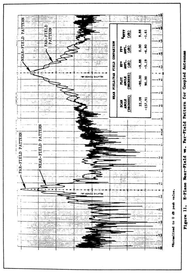
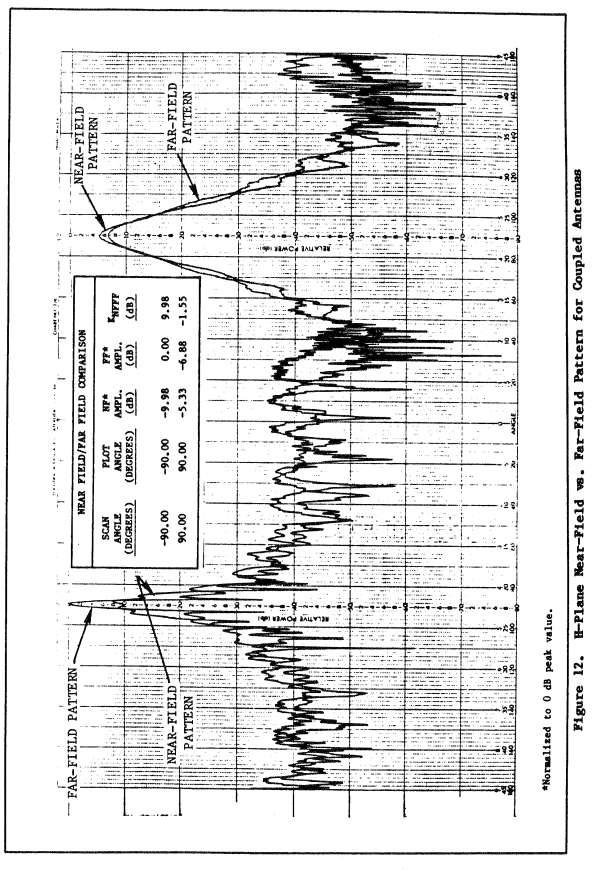
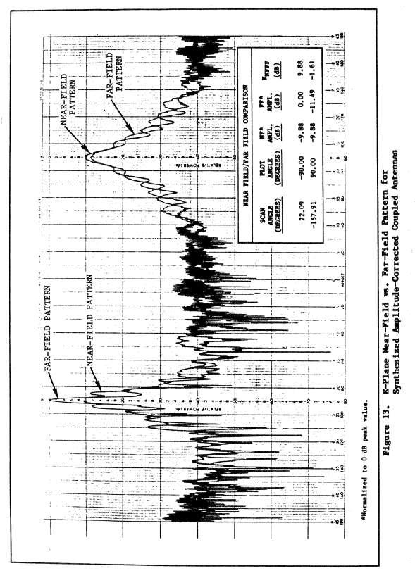
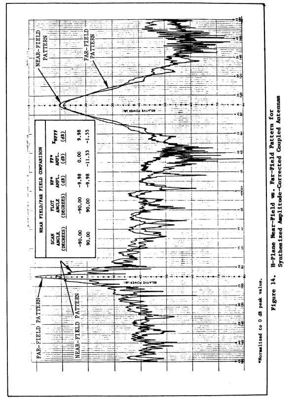
20 SHARED-SCAN GAIN COMPARISON MEASUREMENTS In an effort to reduce the lengthy data acquisition and data transformation times required to perform successive near-field scans we have devised a novel range configuration which halves the measurement time. It permits both the test antenna and gain standards to share the same mechanical scan but with the main beams occupying different coverage regions. The arrangement used called for mounting both antennas in equatorial configuration with their main beam peaks located at diametrically opposite positions on the equator. In principle the same approach is possible in polar mounting orientation but our positioner was not convenient for the polar case. The ports of the two antenna are coupled together so that the receiver signal is the sum of the two phasors, and both patterns show up in the data. An assumption here is that both antennas have negligible backlobes. See Figure 10. This setup makes the AUT and the standard gain horn look like one composite antenna with two main beams. Figures 11 and 12 show near-field vs. far-field patterns for the two principal planes in this configuration. All the data was acquired in a single scan. The measured gain of the AUT for this case was db. The variable attenuator shown in Figure 10 was not used for the measurements of Figures 11 and 12. Had we used it and adjusted its level so that the near-field levels in the directions of interest were equal for both antennas, as shown in Figures 13 and 14, the quantity K SGH, NFFF K SGH, NFFF would have fallen directly out of the transformed data.
21
22
23
24
25
26 SUMMARY We have performed gain comparison measurements using spherical near-field scanning. The measurements were made using standard RF hardware with the currently available Scientific-Atlanta 2022A Spherical Near-Field Antenna Analyzer. Measurement errors on the order of.5 db were estimated, and measurement of impedance mismatch and accurate gain standard calibration could reduce these errors significantly. A method for combining the signals at the terminals of the two antennas involved (thereby effectively making them one antenna) was developed. This halved the data acquisition time since only one spherical near-field scan was required. The Scientific-Atlanta 2022A Spherical Near-Field Antenna Analyzer can be used with the procedures described above to make gain comparison measurements at near-field range lengths, thereby providing the same advantages for gain measurements as it already provides for pattern measurements.
Antenna Measurement Uncertainty Method for Measurements in Compact Antenna Test Ranges
 Antenna Measurement Uncertainty Method for Measurements in Compact Antenna Test Ranges Stephen Blalock & Jeffrey A. Fordham MI Technologies Suwanee, Georgia, USA Abstract Methods for determining the uncertainty
HOW TO CHOOSE AN ANTENNA RANGE CONFIGURATION
 HOW TO CHOOSE AN ANTENNA RANGE CONFIGURATION Donnie Gray Nearfield Systems, Inc. 1330 E. 223 rd St, Bldg 524 Carson, CA 90745 (310) 518-4277 dgray@nearfield.com Abstract Choosing the proper antenna range
A COMPOSITE NEAR-FIELD SCANNING ANTENNA RANGE FOR MILLIMETER-WAVE BANDS
 A COMPOSITE NEAR-FIELD SCANNING ANTENNA RANGE FOR MILLIMETER-WAVE BANDS Doren W. Hess dhess@mi-technologies.com John McKenna jmckenna@mi-technologies.com MI-Technologies 1125 Satellite Boulevard Suite
PRACTICAL GAIN MEASUREMENTS
 PRACTICAL GAIN MEASUREMENTS Marion Baggett MI Technologies 1125 Satellite Boulevard Suwanee, GA 30022 mbaggett@mi-technologies.com ABSTRACT Collecting accurate gain measurements on antennas is one of the
SPHERICAL NEAR-FIELD MEASUREMENTS AT UHF FREQUENCIES WITH COMPLETE UNCERTAINTY ANALYSIS
 SPHERICAL NEAR-FIELD MEASUREMENTS AT UHF FREQUENCIES WITH COMPLETE UNCERTAINTY ANALYSIS Allen Newell, Patrick Pelland Nearfield Systems Inc. 19730 Magellan Drive, Torrance, CA 90502-1104 Brian Park, Ted
A SIMPLE ANALYSIS OF NEAR-FIELD BORESIGHT ERROR REQUIREMENTS
 A SIMPE ANAYSIS OF NEAR-FIED BORESIGHT ERROR REQUIREMENTS Doren W. Hess * MI Technologies 500 River Green Parkway Duluth, GA 30096 (678) 75-8380 dhess@mi-technologies.com ABSTRACT The need to measure the
SPHERICAL NEAR-FIELD SELF-COMPARISON MEASUREMENTS
 SPHERICAL NEAR-FIELD SELF-COMPARISON MEASUREMENTS Greg Hindman, Allen C. Newell Nearfield Systems Inc. 1973 Magellan Dr. Torrance, CA 952 ABSTRACT Spherical near-field measurements require an increased
ANTENNA INTRODUCTION / BASICS
 ANTENNA INTRODUCTION / BASICS RULES OF THUMB: 1. The Gain of an antenna with losses is given by: 2. Gain of rectangular X-Band Aperture G = 1.4 LW L = length of aperture in cm Where: W = width of aperture
Estimating Measurement Uncertainties in Compact Range Antenna Measurements
 Estimating Measurement Uncertainties in Compact Range Antenna Measurements Stephen Blalock & Jeffrey A. Fordham MI Technologies Suwanee, Georgia, USA sblalock@mitechnologies.com jfordham@mitechnolgies.com
ANECHOIC CHAMBER EVALUATION
 ANECHOIC CHAMBER EVALUATION Antenna Measurement Techniques Association Conference October 3 - October 7, 1994 Karl Haner Nearfield Systems Inc. 1330 E. 223rd Street Bldg.524 Carson, CA 90745 USA (310)
PRIME FOCUS FEEDS FOR THE COMPACT RANGE
 PRIME FOCUS FEEDS FOR THE COMPACT RANGE John R. Jones Prime focus fed paraboloidal reflector compact ranges are used to provide plane wave illumination indoors at small range lengths for antenna and radar
ANTENNA INTRODUCTION / BASICS
 Rules of Thumb: 1. The Gain of an antenna with losses is given by: G 0A 8 Where 0 ' Efficiency A ' Physical aperture area 8 ' wavelength ANTENNA INTRODUCTION / BASICS another is:. Gain of rectangular X-Band
Aperture Antennas. Reflectors, horns. High Gain Nearly real input impedance. Huygens Principle
 Antennas 97 Aperture Antennas Reflectors, horns. High Gain Nearly real input impedance Huygens Principle Each point of a wave front is a secondary source of spherical waves. 97 Antennas 98 Equivalence
A CYLINDRICAL NEAR-FIELD VS. SPHERICAL NEAR-FIELD ANTENNA TEST COMPARISON
 A CYLINDRICAL NEAR-FIELD VS. SPHERICAL NEAR-FIELD ANTENNA TEST COMPARISON Jeffrey Fordham VP, Sales and Marketing MI Technologies, 4500 River Green Parkway, Suite 200 Duluth, GA 30096 jfordham@mi-technologies.com
Accuracy Estimation of Microwave Holography from Planar Near-Field Measurements
 Accuracy Estimation of Microwave Holography from Planar Near-Field Measurements Christopher A. Rose Microwave Instrumentation Technologies River Green Parkway, Suite Duluth, GA 9 Abstract Microwave holography
A DUAL-PORTED, DUAL-POLARIZED SPHERICAL NEAR-FIELD PROBE
 A DUAL-PORTED, DUAL-POLARIZED SPHERICAL NEAR-FIELD PROBE by J. R. Jones and D. P. Hardin Scientific-Atlanta, Inc. Spherical near-field testing of antennas requires the acquisition of a great volume of
Further Refining and Validation of RF Absorber Approximation Equations for Anechoic Chamber Predictions
 Further Refining and Validation of RF Absorber Approximation Equations for Anechoic Chamber Predictions Vince Rodriguez, NSI-MI Technologies, Suwanee, Georgia, USA, vrodriguez@nsi-mi.com Abstract Indoor
A DUAL-PORTED PROBE FOR PLANAR NEAR-FIELD MEASUREMENTS
 A DUAL-PORTED PROBE FOR PLANAR NEAR-FIELD MEASUREMENTS W. Keith Dishman, Doren W. Hess, and A. Renee Koster ABSTRACT A dual-linearly polarized probe developed for use in planar near-field antenna measurements
NTT DOCOMO Technical Journal. Method for Measuring Base Station Antenna Radiation Characteristics in Anechoic Chamber. 1.
 Base Station Antenna Directivity Gain Method for Measuring Base Station Antenna Radiation Characteristics in Anechoic Chamber Base station antennas tend to be long compared to the wavelengths at which
Uncertainty Considerations In Spherical Near-field Antenna Measurements
 Uncertainty Considerations In Spherical Near-field Antenna Measurements Phil Miller National Physical Laboratory Industry & Innovation Division Teddington, United Kingdom Outline Introduction and Spherical
METHODS TO ESTIMATE AND REDUCE LEAKAGE BIAS ERRORS IN PLANAR NEAR-FIELD ANTENNA MEASUREMENTS
 METHODS TO ESTIMATE AND REDUCE LEAKAGE BIAS ERRORS IN PLANAR NEAR-FIELD ANTENNA MEASUREMENTS Allen C. Newell Newell Near-Field Consultants 235 Vassar Drive, Boulder CO 835 Jeff Guerrieri and Katie MacReynolds
RAYTHEON 23 x 22 50GHZ PULSE SYSTEM
 RAYTHEON 23 x 22 50GHZ PULSE SYSTEM Terry Speicher Nearfield Systems, Incorporated 1330 E. 223 rd Street, Bldg. 524 Carson, CA 90745 www.nearfield.com Angelo Puzella and Joseph K. Mulcahey Raytheon Electronic
Accurate Planar Near-Field Results Without Full Anechoic Chamber
 Accurate Planar Near-Field Results Without Full Anechoic Chamber Greg Hindman, Stuart Gregson, Allen Newell Nearfield Systems Inc. Torrance, CA, USA ghindman@nearfield.com Abstract - Planar near-field
HIGH ACCURACY CROSS-POLARIZATION MEASUREMENTS USING A SINGLE REFLECTOR COMPACT RANGE
 HIGH ACCURACY CROSS-POLARIZATION MEASUREMENTS USING A SINGLE REFLECTOR COMPACT RANGE Christopher A. Rose Microwave Instrumentation Technologies 4500 River Green Parkway, Suite 200 Duluth, GA 30096 Abstract
The Design of an Automated, High-Accuracy Antenna Test Facility
 The Design of an Automated, High-Accuracy Antenna Test Facility T. JUD LYON, MEMBER, IEEE, AND A. RAY HOWLAND, MEMBER, IEEE Abstract This paper presents the step-by-step application of proven far-field
APPLICATIONS OF PORTABLE NEAR-FIELD ANTENNA MEASUREMENT SYSTEMS
 APPLICATIONS OF PORTABLE NEAR-FIELD ANTENNA MEASUREMENT SYSTEMS Greg Hindman Nearfield Systems Inc. 1330 E. 223rd Street Bldg. 524 Carson, CA 90745 (213) 518-4277 ABSTRACT Portable near-field measurement
Chapter 5. Array of Star Spirals
 Chapter 5. Array of Star Spirals The star spiral was introduced in the previous chapter and it compared well with the circular Archimedean spiral. This chapter will examine the star spiral in an array
PERFORMANCE CONSIDERATIONS FOR PULSED ANTENNA MEASUREMENTS
 PERFORMANCE CONSIDERATIONS FOR PULSED ANTENNA MEASUREMENTS David S. Fooshe Nearfield Systems Inc., 19730 Magellan Drive Torrance, CA 90502 USA ABSTRACT Previous AMTA papers have discussed pulsed antenna
PROBE CORRECTION EFFECTS ON PLANAR, CYLINDRICAL AND SPHERICAL NEAR-FIELD MEASUREMENTS
 PROBE CORRECTION EFFECTS ON PLANAR, CYLINDRICAL AND SPHERICAL NEAR-FIELD MEASUREMENTS Greg Hindman, David S. Fooshe Nearfield Systems Inc. 133 E. 223rd Street Bldg 524 Carson, CA 9745 USA (31) 518-4277
Near-Field Antenna Measurements using a Lithium Niobate Photonic Probe
 Near-Field Antenna Measurements using a Lithium Niobate Photonic Probe Vince Rodriguez 1, Brett Walkenhorst 1, and Jim Toney 2 1 NSI-MI Technologies, Suwanee, Georgia, USA, Vrodriguez@nsi-mi.com 2 Srico,
REFLECTION SUPPRESSION IN LARGE SPHERICAL NEAR-FIELD RANGE
 REFLECTION SUPPRESSION IN LARGE SPHERICAL NEAR-FIELD RANGE Greg Hindman & Allen C. Newell Nearfield Systems Inc. 1973 Magellan Drive Torrance, CA 952 ABSTRACT Reflections in antenna test ranges can often
Sub-millimeter Wave Planar Near-field Antenna Testing
 Sub-millimeter Wave Planar Near-field Antenna Testing Daniёl Janse van Rensburg 1, Greg Hindman 2 # Nearfield Systems Inc, 1973 Magellan Drive, Torrance, CA, 952-114, USA 1 drensburg@nearfield.com 2 ghindman@nearfield.com
Numerical Calibration of Standard Gain Horns and OEWG Probes
 Numerical Calibration of Standard Gain Horns and OEWG Probes Donald G. Bodnar dbodnar@mi-technologies.com MI Technologies 1125 Satellite Blvd, Suite 100 Suwanee, GA 30024 ABSTRACT The gain-transfer technique
MISSION TO MARS - IN SEARCH OF ANTENNA PATTERN CRATERS
 MISSION TO MARS - IN SEARCH OF ANTENNA PATTERN CRATERS Greg Hindman & Allen C. Newell Nearfield Systems Inc. 197 Magellan Drive Torrance, CA 92 ABSTRACT Reflections in anechoic chambers can limit the performance
ANECHOIC CHAMBER DIAGNOSTIC IMAGING
 ANECHOIC CHAMBER DIAGNOSTIC IMAGING Greg Hindman Dan Slater Nearfield Systems Incorporated 1330 E. 223rd St. #524 Carson, CA 90745 USA (310) 518-4277 Abstract Traditional techniques for evaluating the
A TECHNIQUE TO EVALUATE THE IMPACT OF FLEX CABLE PHASE INSTABILITY ON mm-wave PLANAR NEAR-FIELD MEASUREMENT ACCURACIES
 A TECHNIQUE TO EVALUATE THE IMPACT OF FLEX CABLE PHASE INSTABILITY ON mm-wave PLANAR NEAR-FIELD MEASUREMENT ACCURACIES Daniël Janse van Rensburg Nearfield Systems Inc., 133 E, 223rd Street, Bldg. 524,
ADVANTAGES AND DISADVANTAGES OF VARIOUS HEMISPHERICAL SCANNING TECHNIQUES
 ADVANTAGES AND DISADVANTAGES OF VARIOUS HEMISPHERICAL SCANNING TECHNIQUES Eric Kim & Anil Tellakula MI Technologies Suwanee, GA, USA ekim@mitechnologies.com Abstract - When performing far-field or near-field
Upgraded Planar Near-Field Test Range For Large Space Flight Reflector Antennas Testing from L to Ku-Band
 Upgraded Planar Near-Field Test Range For Large Space Flight Reflector Antennas Testing from L to Ku-Band Laurent Roux, Frédéric Viguier, Christian Feat ALCATEL SPACE, Space Antenna Products Line 26 avenue
Measurement Uncertainties in Millimeter Wave On-Chip Antenna Measurements
 Measurement Uncertainties in Millimeter Wave On-Chip Antenna Measurements Edward Szpindor, Wenji Zhang, Per O, Iversen MVG - Orbit/F Horsham, PA, USA Abstract As a result of recent technical and regulatory
33 BY 16 NEAR-FIELD MEASUREMENT SYSTEM
 33 BY 16 NEAR-FIELD MEASUREMENT SYSTEM ABSTRACT Nearfield Systems Inc. (NSI) has delivered the world s largest vertical near-field measurement system. With a 30m by 16m scan area and a frequency range
Characterization of a Photonics E-Field Sensor as a Near-Field Probe
 Characterization of a Photonics E-Field Sensor as a Near-Field Probe Brett T. Walkenhorst 1, Vince Rodriguez 1, and James Toney 2 1 NSI-MI Technologies Suwanee, GA 30024 2 SRICO Columbus, OH 43235 bwalkenhorst@nsi-mi.com
A LARGE COMBINATION HORIZONTAL AND VERTICAL NEAR FIELD MEASUREMENT FACILITY FOR SATELLITE ANTENNA CHARACTERIZATION
 A LARGE COMBINATION HORIZONTAL AND VERTICAL NEAR FIELD MEASUREMENT FACILITY FOR SATELLITE ANTENNA CHARACTERIZATION John Demas Nearfield Systems Inc. 1330 E. 223rd Street Bldg. 524 Carson, CA 90745 USA
The Importance of Polarization Purity Author: Lars J Foged, Scientific Director at MVG (Microwave Vision Group)
") The Importance of Polarization Purity Author: Lars J Foged, Scientific Director at MVG (Microwave Vision Group) The polarization purity of an antenna system is an important characteristic, particularly
The Importance of Polarization Purity Author: Lars J Foged, Scientific Director at MVG (Microwave Vision Group) The polarization purity of an antenna system is an important characteristic, particularly
Fundamentals. Senior Project Manager / AEO Taiwan. Philip Chang
 mmwave OTA Fundamentals Senior Project Manager / AEO Taiwan Philip Chang L A R G E LY D R I V E N B Y N E W W I R E L E S S T E C H N O L O G I E S A N D F R E Q U E N C Y B A N D S 1. Highly integrated
Structural Correction of a Spherical Near-Field Scanner for mm-wave Applications
 Structural Correction of a Spherical Near-Field Scanner for mm-wave Applications Daniël Janse van Rensburg & Pieter Betjes Nearfield Systems Inc. 19730 Magellan Drive Torrance, CA 90502-1104, USA Abstract
A Method for Gain over Temperature Measurements Using Two Hot Noise Sources
 A Method for Gain over Temperature Measurements Using Two Hot Noise Sources Vince Rodriguez and Charles Osborne MI Technologies: Suwanee, 30024 GA, USA vrodriguez@mitechnologies.com Abstract P Gain over
PLANE-WAVE SYNTHESIS FOR COMPACT ANTENNA TEST RANGE BY FEED SCANNING
 Progress In Electromagnetics Research M, Vol. 22, 245 258, 2012 PLANE-WAVE SYNTHESIS FOR COMPACT ANTENNA TEST RANGE BY FEED SCANNING H. Wang 1, *, J. Miao 2, J. Jiang 3, and R. Wang 1 1 Beijing Huahang
Exercise 1-3. Radar Antennas EXERCISE OBJECTIVE DISCUSSION OUTLINE DISCUSSION OF FUNDAMENTALS. Antenna types
 Exercise 1-3 Radar Antennas EXERCISE OBJECTIVE When you have completed this exercise, you will be familiar with the role of the antenna in a radar system. You will also be familiar with the intrinsic characteristics
Over the Air Testing: Important Antenna Parameters, Testing Methodologies and Standards
 Over the Air Testing: Important Antenna Parameters, Testing Methodologies and Standards Alexander Naehring Rohde & Schwarz GmbH & Co. KG Muehldorfstr. 15, 81671 Munich, Germany Email: alexander.naehring@rohde-schwarz.com
The Discussion of this exercise covers the following points:
 Exercise 3-2 Frequency-Modulated CW Radar EXERCISE OBJECTIVE When you have completed this exercise, you will be familiar with FM ranging using frequency-modulated continuous-wave (FM-CW) radar. DISCUSSION
Dependence of Antenna Cross-polarization Performance on Waveguide-to-Coaxial Adapter Design
 Dependence of Antenna Cross-polarization Performance on Waveguide-to-Coaxial Adapter Design Vince Rodriguez, Edwin Barry, Steve Nichols NSI-MI Technologies Suwanee, GA, USA vrodriguez@nsi-mi.com Abstract
KULLIYYAH OF ENGINEERING
 KULLIYYAH OF ENGINEERING DEPARTMENT OF ELECTRICAL & COMPUTER ENGINEERING ANTENNA AND WAVE PROPAGATION LABORATORY (ECE 4103) EXPERIMENT NO 3 RADIATION PATTERN AND GAIN CHARACTERISTICS OF THE DISH (PARABOLIC)
SPHERICAL NEAR-FIELD ANTENNA MEASUREMENTS: A REVIEW OF CORRECTION TECHNIQUES
 SPHERICAL NEAR-FIELD ANTENNA MEASUREMENTS: A REVIEW OF CORRECTION TECHNIQUES Doren W. Hess MI Technologies, 1125 Satellite Boulevard, Suite 100 Suwanee, GA 30024, U.S.A. dhess@mi-technologies.com Abstract
Using Frequency Diversity to Improve Measurement Speed Roger Dygert MI Technologies, 1125 Satellite Blvd., Suite 100 Suwanee, GA 30024
 Using Frequency Diversity to Improve Measurement Speed Roger Dygert MI Technologies, 1125 Satellite Blvd., Suite 1 Suwanee, GA 324 ABSTRACT Conventional antenna measurement systems use a multiplexer or
60 GHz antenna measurement setup using a VNA without external frequency conversion
 Downloaded from orbit.dtu.dk on: Mar 11, 2018 60 GHz antenna measurement setup using a VNA without external frequency conversion Popa, Paula Irina; Pivnenko, Sergey; Bjørstorp, Jeppe Majlund; Breinbjerg,
A. A. Kishk and A. W. Glisson Department of Electrical Engineering The University of Mississippi, University, MS 38677, USA
 Progress In Electromagnetics Research, PIER 33, 97 118, 2001 BANDWIDTH ENHANCEMENT FOR SPLIT CYLINDRICAL DIELECTRIC RESONATOR ANTENNAS A. A. Kishk and A. W. Glisson Department of Electrical Engineering
Comparison of Various RF Calibration Techniques in Production: Which is Right for You? Daniel Bock, Ph.D.
 Comparison of Various RF Calibration Techniques in Production: Which is Right for You? Daniel Bock, Ph.D. Overview Introduction How does Calibration Work Types of Calibrations Comparison of Calibration
ELEC4604. RF Electronics. Experiment 1
 ELEC464 RF Electronics Experiment ANTENNA RADATO N PATTERNS. ntroduction The performance of RF communication systems depend critically on the radiation characteristics of the antennae it employs. These
Non-Ideal Quiet Zone Effects on Compact Range Measurements
 Non-Ideal Quiet Zone Effects on Compact Range Measurements David Wayne, Jeffrey A. Fordham, John McKenna MI Technologies Suwanee, Georgia, USA Abstract Performance requirements for compact ranges are typically
Principles of Planar Near-Field Antenna Measurements. Stuart Gregson, John McCormick and Clive Parini. The Institution of Engineering and Technology
 Principles of Planar Near-Field Antenna Measurements Stuart Gregson, John McCormick and Clive Parini The Institution of Engineering and Technology Contents Preface xi 1 Introduction 1 1.1 The phenomena
Antennas and Propagation. Chapter 4: Antenna Types
 Antennas and Propagation : Antenna Types 4.4 Aperture Antennas High microwave frequencies Thin wires and dielectrics cause loss Coaxial lines: may have 10dB per meter Waveguides often used instead Aperture
Performance Analysis of a Patch Antenna Array Feed For A Satellite C-Band Dish Antenna
 Cyber Journals: Multidisciplinary Journals in Science and Technology, Journal of Selected Areas in Telecommunications (JSAT), November Edition, 2011 Performance Analysis of a Patch Antenna Array Feed For
Introduction Antenna Ranges Radiation Patterns Gain Measurements Directivity Measurements Impedance Measurements Polarization Measurements Scale
 Chapter 17 : Antenna Measurement Introduction Antenna Ranges Radiation Patterns Gain Measurements Directivity Measurements Impedance Measurements Polarization Measurements Scale Model Measurements 1 Introduction
Millimeter Spherical µ-lab System from Orbit/FR
 Millimeter Spherical µ-lab System from Orbit/FR Jim Puri Sr. Applications Engineer Orbit/FR, Inc. a Microwave Vision Group company Keysight Technologies and MVG Orbit/FR Partners in Radiated Measurement
Keywords: cylindrical near-field acquisition, mechanical and electrical errors, uncertainty, directivity.
 UNCERTAINTY EVALUATION THROUGH SIMULATIONS OF VIRTUAL ACQUISITIONS MODIFIED WITH MECHANICAL AND ELECTRICAL ERRORS IN A CYLINDRICAL NEAR-FIELD ANTENNA MEASUREMENT SYSTEM S. Burgos, M. Sierra-Castañer, F.
This is a preview - click here to buy the full publication
 TECHNICAL REPORT IEC TR 63170 Edition 1.0 2018-08 colour inside Measurement procedure for the evaluation of power density related to human exposure to radio frequency fields from wireless communication
An Introduction to Antennas
 May 11, 010 An Introduction to Antennas 1 Outline Antenna definition Main parameters of an antenna Types of antennas Antenna radiation (oynting vector) Radiation pattern Far-field distance, directivity,
Real-Time Scanning Goniometric Radiometer for Rapid Characterization of Laser Diodes and VCSELs
 Real-Time Scanning Goniometric Radiometer for Rapid Characterization of Laser Diodes and VCSELs Jeffrey L. Guttman, John M. Fleischer, and Allen M. Cary Photon, Inc. 6860 Santa Teresa Blvd., San Jose,
z t h l g 2009 John Wiley & Sons, Inc. Published 2009 by John Wiley & Sons, Inc.
 x w z t h l g Figure 10.1 Photoconductive switch in microstrip transmission-line geometry: (a) top view; (b) side view. Adapted from [579]. Copyright 1983, IEEE. I g G t C g V g V i V r t x u V t Z 0 Z
Practical Considerations for Radiated Immunities Measurement using ETS-Lindgren EMC Probes
 Practical Considerations for Radiated Immunities Measurement using ETS-Lindgren EMC Probes Detectors/Modulated Field ETS-Lindgren EMC probes (HI-6022/6122, HI-6005/6105, and HI-6053/6153) use diode detectors
PHYS2090 OPTICAL PHYSICS Laboratory Microwaves
 PHYS2090 OPTICAL PHYSICS Laboratory Microwaves Reference Hecht, Optics, (Addison-Wesley) 1. Introduction Interference and diffraction are commonly observed in the optical regime. As wave-particle duality
Introduction to Radar Systems. Radar Antennas. MIT Lincoln Laboratory. Radar Antennas - 1 PRH 6/18/02
 Introduction to Radar Systems Radar Antennas Radar Antennas - 1 Disclaimer of Endorsement and Liability The video courseware and accompanying viewgraphs presented on this server were prepared as an account
WIESON TECHNOLOGIES CO., LTD.
 WIESON 3D CHAMBER TEST REPORT G121HT632-1 Page 1 of 2 I. Summary: This report to account for the measurement setup and result of the Antenna. The measurement setup includes s-parameter, pattern, and gain
UNIT Explain the radiation from two-wire. Ans: Radiation from Two wire
 UNIT 1 1. Explain the radiation from two-wire. Radiation from Two wire Figure1.1.1 shows a voltage source connected two-wire transmission line which is further connected to an antenna. An electric field
Dr. John S. Seybold. November 9, IEEE Melbourne COM/SP AP/MTT Chapters
 Antennas Dr. John S. Seybold November 9, 004 IEEE Melbourne COM/SP AP/MTT Chapters Introduction The antenna is the air interface of a communication system An antenna is an electrical conductor or system
The magnetic surface current density is defined in terms of the electric field at an aperture as follows: 2E n (6.1)
") Chapter 6. Aperture antennas Antennas where radiation occurs from an open aperture are called aperture antennas. xamples include slot antennas, open-ended waveguides, rectangular and circular horn antennas,
Chapter 6. Aperture antennas Antennas where radiation occurs from an open aperture are called aperture antennas. xamples include slot antennas, open-ended waveguides, rectangular and circular horn antennas,
BROADBAND GAIN STANDARDS FOR WIRELESS MEASUREMENTS
 BROADBAND GAIN STANDARDS FOR WIRELESS MEASUREMENTS James D. Huff Carl W. Sirles The Howland Company, Inc. 4540 Atwater Court, Suite 107 Buford, Georgia 30518 USA Abstract Total Radiated Power (TRP) and
A Directional, Low-Profile Zero-Phase-Shift-Line (ZPSL) Loop Antenna for UHF Near-Field RFID Applications
 Loop Antenna for UHF Near-Field RFID Applications") A Directional, Low-Profile Zero-Phase-Shift-Line (ZPSL) Loop Antenna for UHF Near-Field RFID Applications YunjiaZeng (1), Xianming Qing (1), Zhi Ning Chen (2) (1) Institute for Infocomm Research, Singapore
A Directional, Low-Profile Zero-Phase-Shift-Line (ZPSL) Loop Antenna for UHF Near-Field RFID Applications YunjiaZeng (1), Xianming Qing (1), Zhi Ning Chen (2) (1) Institute for Infocomm Research, Singapore
Standing Waves and Voltage Standing Wave Ratio (VSWR)
") Exercise 3-1 Standing Waves and Voltage Standing Wave Ratio (VSWR) EXERCISE OBJECTIVES Upon completion of this exercise, you will know how standing waves are created on transmission lines. You will be
Exercise 3-1 Standing Waves and Voltage Standing Wave Ratio (VSWR) EXERCISE OBJECTIVES Upon completion of this exercise, you will know how standing waves are created on transmission lines. You will be
Aries Kapton CSP socket
 Aries Kapton CSP socket Measurement and Model Results prepared by Gert Hohenwarter 5/19/04 1 Table of Contents Table of Contents... 2 OBJECTIVE... 3 METHODOLOGY... 3 Test procedures... 4 Setup... 4 MEASUREMENTS...
Antenna Theory and Design
 Antenna Theory and Design Antenna Theory and Design Associate Professor: WANG Junjun 王珺珺 School of Electronic and Information Engineering, Beihang University F1025, New Main Building wangjunjun@buaa.edu.cn
Continuous Arrays Page 1. Continuous Arrays. 1 One-dimensional Continuous Arrays. Figure 1: Continuous array N 1 AF = I m e jkz cos θ (1) m=0
 m=0") Continuous Arrays Page 1 Continuous Arrays 1 One-dimensional Continuous Arrays Consider the 2-element array we studied earlier where each element is driven by the same signal (a uniform excited array),
Continuous Arrays Page 1 Continuous Arrays 1 One-dimensional Continuous Arrays Consider the 2-element array we studied earlier where each element is driven by the same signal (a uniform excited array),
A Reduced Uncertainty Method for Gain over Temperature Measurements in an Anechoic Chamber
 A Reduced Uncertainty Method for Gain over Temperature Measurements in an Anechoic Chamber Vince Rodriguez and Charles Osborne MI Technologies Suwanee, GA, USA vrodriguez@mitechnologies.com Abstract P
Keysight Technologies Making Accurate Intermodulation Distortion Measurements with the PNA-X Network Analyzer, 10 MHz to 26.5 GHz
 Keysight Technologies Making Accurate Intermodulation Distortion Measurements with the PNA-X Network Analyzer, 10 MHz to 26.5 GHz Application Note Overview This application note describes accuracy considerations
REPORT ITU-R BT Radiation pattern characteristics of UHF * television receiving antennas
 Rep. ITU-R BT.2138 1 REPORT ITU-R BT.2138 Radiation pattern characteristics of UHF * television receiving antennas (2008) 1 Introduction This Report describes measurements of the radiation pattern characteristics
ALIGNMENT SENSITIVITY AND CORRECTION METHODS FOR MILLIMETER- WAVE SPHERICAL NEAR-FIELD MEASUREMENTS
 ALIGNMENT SENSITIVITY AND CORRECTION METHODS FOR MILLIMETER- WAVE SPHERICAL NEAR-FIELD MEASUREMENTS Greg Hindman, Allen Newell Nearfield Systems Inc. 1973 Magellan Drive Torrance, CA 952, USA Luciano Dicecca
Lecture 17 z-transforms 2
 Lecture 17 z-transforms 2 Fundamentals of Digital Signal Processing Spring, 2012 Wei-Ta Chu 2012/5/3 1 Factoring z-polynomials We can also factor z-transform polynomials to break down a large system into
The Measurement and Uncertainty Analysis of Antenna Factor of Microwave Antennas Based on Standard Site Method
 Int. J. Communications, Network and System Sciences, 2017, 10, 138-145 http://www.scirp.org/journal/ijcns ISSN Online: 1913-3723 ISSN Print: 1913-3715 The Measurement and ncertainty nalysis of ntenna Factor
Correlation Between Measured and Simulated Parameters of a Proposed Transfer Standard
 Correlation Between Measured and Simulated Parameters of a Proposed Transfer Standard Jim Nadolny AMP Incorporated ABSTRACT Total radiated power of a device can be measured using a mode stirred chamber
Physics 3340 Spring Fourier Optics
 Physics 3340 Spring 011 Purpose Fourier Optics In this experiment we will show how the Fraunhofer diffraction pattern or spatial Fourier transform of an object can be observed within an optical system.
Rotating Coil Measurement Errors*
 Rotating Coil Measurement Errors* Animesh Jain Superconducting Magnet Division Brookhaven National Laboratory, Upton, NY 11973, USA 2 nd Workshop on Beam Dynamics Meets Magnets (BeMa2014) December 1-4,
Electromagnetic Effects, original release, dated 31 October Contents: 17 page document plus 13 Figures. Enclosure (1)
") Electromagnetic Effects, original release, dated 31 October 2005 Contents: 17 page document plus 13 Figures Enclosure (1) Electromagnetic effects. 1. Purpose. To ensure that the addition of fiber optic
Electromagnetic Effects, original release, dated 31 October 2005 Contents: 17 page document plus 13 Figures Enclosure (1) Electromagnetic effects. 1. Purpose. To ensure that the addition of fiber optic
Millimetre Spherical Wave Antenna Pattern Measurements at NPL. Philip Miller May 2009
 Millimetre Spherical Wave Antenna Pattern Measurements at NPL Philip Miller May 2009 The NPL Spherical Range The NPL Spherical Range is a conventional spherical range housed within a 15 m by 7.5 m by 7.5
Experiment 19. Microwave Optics 1
 Experiment 19 Microwave Optics 1 1. Introduction Optical phenomena may be studied at microwave frequencies. Using a three centimeter microwave wavelength transforms the scale of the experiment. Microns
Microstrip Antennas Integrated with Horn Antennas
 53 Microstrip Antennas Integrated with Horn Antennas Girish Kumar *1, K. P. Ray 2 and Amit A. Deshmukh 1 1. Department of Electrical Engineering, I.I.T. Bombay, Powai, Mumbai 400 076, India Phone: 91 22
System configurations. Main features I SG 64 SOLUTION FOR
 T- DualScan SG 64 The most accurate solution for testing antennas and wireless devices: SG 64 has been developed to measure stand alone antennas or antennas integrated in subsystems. It is also ideal for
Network Analysis Basics
 Adolfo Del Solar Application Engineer adolfo_del-solar@agilent.com MD1010 Network B2B Agenda Overview What Measurements do we make? Network Analyzer Hardware Error Models and Calibration Example Measurements
MICROWAVE AND RADAR LAB (EE-322-F) LAB MANUAL VI SEMESTER
 LAB MANUAL VI SEMESTER") 1 MICROWAVE AND RADAR LAB (EE-322-F) MICROWAVE AND RADAR LAB (EE-322-F) LAB MANUAL VI SEMESTER RAO PAHALD SINGH GROUP OF INSTITUTIONS BALANA(MOHINDERGARH)123029 Department Of Electronics and Communication
1 MICROWAVE AND RADAR LAB (EE-322-F) MICROWAVE AND RADAR LAB (EE-322-F) LAB MANUAL VI SEMESTER RAO PAHALD SINGH GROUP OF INSTITUTIONS BALANA(MOHINDERGARH)123029 Department Of Electronics and Communication
IMPROVING AND EXTENDING THE MARS TECHNIQUE TO REDUCE SCATTERING ERRORS
 IMPROVING AND EXTENDING THE MARS TECHNIQUE TO REDUCE SCATTERING ERRORS Greg Hindman & Allen C. Newell Nearfield Systems Inc. 1973 Magellan Drive Torrance, CA 952 ABSTRACT The Mathematical Absorber Reflection
Traveling Wave Antennas
 Traveling Wave Antennas Antennas with open-ended wires where the current must go to zero (dipoles, monopoles, etc.) can be characterized as standing wave antennas or resonant antennas. The current on these