Lasers for Life Sciences
|
|
|
- Eileen Reeves
- 6 years ago
- Views:
Transcription


1 Lasers for Life Sciences 2015 Laser Overview Superior Reliability & Performance


2 Lasers for Life Sciences Overview of Laser Applications Flow Cytometry MPE Imaging Medical Diagnostics Applications: Flow Cytometry Confocal Microscopy Genomics Proteomics Medical Diagnostics Environmental Monitoring Superior Reliability & Performance


3 Lasers for Life Sciences Overview of Laser Applications Confocal Microscopy Medical Instrumentation DNA Sequencing As one of the fastest growing segments for laser-based solutions, Life Sciences covers a broad range of applications from scientific research leading to medical advances, to clinical functions where lasers are used in diagnostics. Life science is important to improve our collective health and well-being, and providing the technology that is vital to the advancement of medicine is a major focus of Coherent s life sciences strategy.* Our lasers enable advances in life science research and clinical and medical applications such as flow cytometry and cell sorting, microscopy, DNA sequencing and retina scanning. Lasers are predominantly used in these applications to excite fluorophores attached to a sample, allowing researchers and clinicians to perform a variety of important tests at both the cellular and molecular level. Lasers for these applications are as varied as the instrument devices themselves, and span the spectrum from continuouswave diode or optically pumped semiconductor lasers (OPSL) to ultrafast titanium:sapphire systems. It is our mission to enable new laser based applications taking advantage of a leadership in innovation. * We do not include medical therapeutic procedures in Life Sciences and have not included our portfolio of lasers for therapeutics such as high power OPSL, semiconductor or CO 2 lasers in this brochure. Toll Free: (800) Tel: (408) Superior Reliability & Performance 1

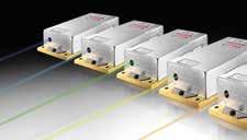
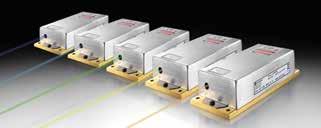
4 Ultimate Choice. Perfect Match. With nearly 50 years of experience in life sciences, Coherent understands that getting the best results requires a laser that perfectly matches your instrument in terms of wavelength, output power, beam quality, output noise, and budget. That s why we offer the industry s widest choice of laser technologies and performance options. So, whether your challenge is in cutting edge research or developing a cost-sensitive clinical instrument, you can be sure you ll find the perfect laser for your needs in the following pages. Sapphire OBIS LG Coherent offers a variety of laser platforms to allow you the freedom to choose. You have the choice, in the coming pages, to select your product by wavelength, power, features or application. Coherent makes it easy for you to optimize the laser to the work being accomplished the perfect match for value and performance. 2 Superior Reliability & Performance tech.sales@coherent.com
 527-3786 Tel: (408)")
5 Ultimate Choice. Perfect Match. OBIS LX, OBIS LS BioRay Toll Free: (800) Tel: (408) Superior Reliability & Performance 3


6 Ultimate Choice. Perfect Match. Choose Your Laser by Application Flow Cytometry: OBIS LX, OBIS LS and Sapphire lasers for visible wavelengths (375 nm to 785 nm) OBIS LG for 355 nm in the UV BioRay for stable, cost-effective compact systems Genesis CX for 355 nm in the UV, high power Medical Diagnostics: OBIS LX, OBIS LS and Sapphire lasers for visible wavelengths (375 nm to 785 nm) OBIS LG for 355 nm in the UV BioRay for stable, cost-effective compact systems Confocal Microscopy: OBIS LX for high speed modulation OBIS Fiber Pigtailed for Single-mode Polarization Maintaining fiber delivery OBIS LS and Sapphire for 458 nm to 594 nm Medical Instrumentation: OBIS LX, OBIS LS and Sapphire lasers for visible wavelengths (375 nm to 785 nm) OBIS LG for 355 nm in the UV BioRay for stable, cost-effective compact systems DNA Sequencing: OBIS LX for 660 nm OBIS LS, OBIS LG or Sapphire for 532 nm Multiphoton Excitation (MPE): for MPE applications, please refer to our Chameleon Ti:Sapphire Lasers beginning on page 116 of this Guide. 4 Superior Reliability & Performance tech.sales@coherent.com
7 Ultimate Choice. Perfect Match. Choose Your Laser by Features Continuous-Wave (CW): Modulation: Analog to 500 KHz Modulation: Analog to 100 KHz and/or Digital to 50 KHz High Speed Modulation: Analog to 500 KHz and/or Digital to 150 MHz BioRay, OBIS LS, OBIS LX, Sapphire, OBIS LG, Genesis CX BioRay OBIS LS OBIS LX Fiber Delivery (Fiber Pigtailed): Single-Mode Polarization-Maintaining Fiber OBIS LX, OBIS LS, Sapphire Single Frequency (Longitudinal Mode) Sapphire SF OPSL (Optically Pumped Semiconductor Laser) OBIS LS, Sapphire, OBIS LG, Genesis CX Adjustable Beam Divergence (User Adjustable Lens) BioRay Compact Laser with common beam, common footprint, common interace, common accessories OBIS LX and OBIS LS 6-Laser Remote, either power Remote and Scientific Remote OBIS LX and OBIS LS Beam Combining with OBIS Galaxy OBIS LX with UFC Connector. Optional OBIS LS and Sapphire with UFC conversion Laser Box for 5-Laser integration with thermal management (cooling), Analog/Digital I/O and laser safety features OBIS LX and LS (frequently purchased with OBIS Galaxy) Toll Free: (800) Tel: (408) Superior Reliability & Performance 5
8 Ultimate Choice. Perfect Match. Choose Your Laser by Wavelength 355 nm OBIS LG at 20 mw 375 nm OBIS LX at 16 and 20 mw 355 nm 375 nm 405 nm OBIS LX at 50, 100 and 200 mw. OBIS LX Fiber Pigtailed at 50 and 100 mw. BioRay at 50 mw. 422 nm OBIS LX at 100 mw 445 nm OBIS LX at 75 mw. OBIS LX Fiber Pigtailed at 45 mw. 405 nm 450 nm BioRay at 50 mw 422 nm 445 nm 450 nm 458 nm 473 nm 488 nm 458 nm OBIS LX at 75 mw. OBIS LX Fiber Pigtailed at 45 mw. Sapphire at 20, 50 and 75 mw. Sapphire FP at 40 mw. 473 nm OBIS LX at 75 mw. OBIS LX Fiber Pigtailed at 50 mw. 488 nm OBIS LX at 50 and 150 mw. OBIS LX Fiber Pigtailed at 30 and 100 mw. OBIS LS at 20, 60, 80, 100 and 150 mw. OBIS LS Fiber Pigtailed at 20, 60, 80 and 120 mw. BioRay at 20 mw. Sapphire at 10, 20, 25, 30, 40, 50, 75, 100, 150, 200 and 300 mw. Sapphire Fiber Pigtailed at 40, 80, 120 and 200 mw. Sapphire Single Frequency at 20, 50 and 100 mw. 505 nm OBIS LX at 50 mw. OBIS LX Fiber Pigtailed at 40 mw. 505 nm 514 nm 520 nm 514 nm OBIS LX at 40 mw. OBIS LX Fiber Pigtailed at 30 mw. OBIS LS at 20 mw. OBIS LS Fiber Pigtailed at 15 mw. Sapphire at 20, 50, 75, 100 and 150 mw. Sapphire Fiber Pigtailed at 40, 80 and 120 mw. 520 nm OBIS LX at 40 mw. BioRay at 50 mw. 6 Superior Reliability & Performance tech.sales@coherent.com
9 Ultimate Choice. Perfect Match. Choose Your Laser by Wavelength 532 nm OBIS LG at 1W. OBIS LS at 20, 50, 80, 100 and 150 mw. OBIS LS Fiber Pigtailed at 40, 60, 80 and 120 mw. Sapphire at 20, 50, 75, 100, 150, 200 and 300 mw. Sapphire Fiber Pigtailed at 40, 80, 120 mw. Sapphire Single Frequency at 20, 50, 100 and 150 mw. 552 nm OBIS LS at 20, 60, 80, 100 and 150 mw. OBIS LS Fiber Pigtailed at 15, 40, 60, 80 and 120 mw. Sapphire at 50, 75, 100, 150 and 200 mw. Sapphire Fiber Pigtailed at 40, 80 and 120 mw. 561 nm OBIS LS at 20, 50, 80, 100 and 150 mw. OBIS LS Fiber Pigtailed at 40, 60, 80 and 120 mw. Sapphire at 20, 50, 75, 100, 150, 200 and 300 mw. Sapphire Fiber Pigtailed at 40, 80, 120, and 200 mw. 568 nm Sapphire at 50, 75, 100, 150 and 200 mw. 532 nm 552 nm 561 nm 568 nm 588 nm 594 nm 588 nm Sapphire at 20, 50, 75 and 100 mw. Sapphire Fiber Pigtailed at 40 mw. 594 nm OBIS LS at 20 and 60 mw. OBIS LS Fiber Pigtailed at 40 mw. Sapphire at 20, 50 and 75 mw. Sapphire Fiber Pigtailed at 40 mw. 637 nm OBIS LX at 140 mw. OBIS LX Fiber Pigtailed at 100 mw. 640 nm OBIS LX at 40 and 100 mw. OBIS LX Fiber Pigtailed at 75 mw. BioRay at 40 mw. 647 nm OBIS LX at 120 mw. OBIS LX Fiber Pigtailed at 100 mw. 637 nm 640 nm 647 nm 660 nm 660 nm OBIS LX at 100 mw. OBIS LX Fiber Pigtailed at 75 mw. 685 nm 685 nm OBIS LX at 40 mw 730 nm OBIS LX at 30 mw 785 nm OBIS LX at 50 mw 730 nm 785 nm Toll Free: (800) Tel: (408) Superior Reliability & Performance 7


10 Ultimate Choice. Perfect Match. Choose Your Laser by Output Power OBIS LG: 20 mw BioRay: 20 mw to 50 mw OBIS LS: 20 mw to 100 mw OBIS LX: 16 mw to 200 mw OBIS FP: 15 mw to 100 mw Sapphire LP: 10 mw to 300 mw Sapphire SF: 20 mw to 150 mw Sapphire FP: 40 mw to 200 mw 8 Superior Reliability & Performance tech.sales@coherent.com

11 Ultimate Choice. Perfect Match. Coherent offers a variety of laser platforms to allow you the freedom to choose. The following pages provide the details of the OBIS LG, OBIS LX, OBIS LS, BioRay, Sapphire and Accessories. Coherent has made it easy for you to optimize the laser to the work being accomplished the perfect match for value and performance. Toll Free: (800) Tel: (408) Superior Reliability & Performance 9
12 Table of Contents Overview of Laser Applications 1 Ultimate Choice. Perfect Match. 2-9 Continuous Wave Lasers OBIS Lasers OBIS OBIS FP OBIS Galaxy OBIS LG OBIS Laser Box OBIS Accessories OBIS Scientific Remote BioRay Lasers BioRay BioRay FR Structured Light Flat Top Projector CUBE Lasers CUBE CUBE FP Radius Lasers ULN Compass Lasers Compass 115M Superior Reliability & Performance tech.sales@coherent.com
13 Table of Contents Continuous Wave Lasers Sapphire Lasers Sapphire LP Sapphire FP Sapphire SF Sapphire Driver Unit Genesis Lasers Genesis CX STM-Series Genesis CX 355 STM Compact (OEM) Genesis MX STM-Series (OEM) Genesis MX STM-Series Genesis MX 607/639 STM (OEM) Genesis MX 607/639 STM Femtosecond Lasers Chameleon Lasers Chameleon Discovery Chameleon Ultra Family Chameleon Vision Chameleon Vision-S Chameleon PreComp Chameleon MPX Laser Measurement and Control Accessories 132 Doing Business with Coherent 133 How to Contact Us 134 Visit the Coherent Website 135 Toll Free: (800) Tel: (408) Superior Reliability & Performance 11

14 OBIS Lasers for Plug-and-Play Simplicity Features Compact and identical foot print, dimensions, beam exit, interface, power supply and protocol Integrated control electronics OEM and end user versions Superior beam quality Analog and digital modulation USB with complete I/O and controls Superior reliability Compatible with MetaMorph and μmanager Software Mechanical Specifications Status Indicator Top View 38 mm (1.5 in.) 3 mm (0.12 in.) 64 mm (2.52 in.) 5 mm (0.2 in.) 30 mm (1.18 in.) 40 mm (1.57 in.) 70 mm (2.76 in.) 4X Ø3.18 mm (0.13 in.) Thru Laser Exit Aperture M6 X 0.75 Thread 2.54 mm Deep Front View Safety Shutter OEM Label Rear View with OEM Label Removed 19 mm (0.75 in.) Fan USB Power 15.5 mm (0.61 in.) Rear View SDR 12 Superior Reliability & Performance tech.sales@coherent.com
15 OBIS Lasers for Plug-and-Play Simplicity System Specifications OBIS 375LX 405LX 413LX* Wavelength 1 (nm) Output Power 2 (mw) , 100, Spatial Mode TEM00 TEM00 TEM00 M 2 (Beam Quality) 3 _<1.3 _<1.2 _<1.3 _<1.2 Beam Asymmetry _<1:1.2 _<1:1.2 _<1:1.2 Beam Diameter at 1/e 2 (mm) 0.7 ± ± ±0.1 Beam Divergence (mrad, full-angle) <1 <1 <1 Pointing Stability (μrad) <30 <30 <30 (over 2 hours after warm-up and ±3 C) Pointing Stability Over Temp. (μrad/ C) <5 <5 <5 RMS Noise (%)(20 Hz to 20 MHz) _<0.05 _<0.05 _<0.05 Peak-to-Peak Noise (%)(20 Hz to 20 khz) <0.5 <0.5 <0.5 Long-term Power Stability (%)(8 hrs., ±3 C) <2 <2 <2 Warm-up Time 4 (minutes)(from cold start) <5 <5 <5 Polarization Ratio Minimum 100:1, Vertical ±5 Laser Drive Modes CW, Analog Modulation, Digital Modulation and Computer Control Digital Modulation Maximum Bandwidth (MHz) Rise Time (10% to 90%)(nsec) <5 <2 <2 Fall Time (90% to 10%)(nsec) <5 <2 <2 Modulation Depth (extinction ratio) Infinite at 0 Hz, Infinite at 0 Hz, Infinite at 0 Hz, >250:1 at 75 MHz >250:1 at 150 MHz >250:1 at 150 MHz Analog Modulation Maximum Bandwidth (khz) Rise Time (10% to 90%)(nsec) <700 <700 <700 Fall Time (90% to 10%)(nsec) <700 <700 <700 Modulation Depth (extinction ratio) >1,000,000:1 >1,000,000:1 >1,000,000:1 Static Alignment Tolerances Beam Position from <1 <1 <1 Reference 5 (mm) Beam Angle 5 (mrad) <5 <5 <5 Beam Waist Position at Exit Window (mm) n/a n/a n/a Laser Safety Classification 3b 3b 3b ESD Protection 6 Level 4 Level 4 Level 4 Power Consumption (W) Typical 5, Typical 5, Typical 5, Max. 13 Max. 13 Max. 13 Laser Head Baseplate Temp. (Max., C) Heat Dissipation of Laser Head 7 (W) Typical 5, Typical 5, Typical 5, Max. 13 Max. 13 Max. 13 Ambient Temperature 8 Operating Condition 9 ( C) 10 to to to 50 Non-operating Condition ( C) -20 to to to 60 Shock Tolerance (g)(6 ms) Laser-to-laser wavelength tolerance ±2 nm for all OBIS LS versions. For OBIS LX wavelength tolerance of ±5 nm except for 413LX with a 410 nm to 420 nm range, 520LX with a 520 nm to 530 nm range, 640LX with 635 nm to 644 nm range, 660LX with 652 nm to 665 nm range and 685LX with 675 nm to 695 nm range. 2 Output power is variable in CW Mode from 1 mw (1% for LX Models) to 110% of rated power. Specifications are valid for 100% power. For LS versions all residual laser emission at 808 nm pumplight or fundamental <0.1 mw. 3 For LX versions the M 2 measured with ModeMaster with 90/10 clip levels. 4 For LS versions typical power-on delay 1 minute. For LX versions typical power-on delay 0.1 minutes. 5 See mechanical drawing for exit beam location. 6 Electro-Static Discharge Standard IEC , Typically 85% of heat load through the base plate. See Users Manual for more detail. 8 Non-Condensing. See User Manual for more detail. 9 For LS versions laser head baseplate temperature needs to be maintained at <_40 C. * Preliminary version. Toll Free: (800) Tel: (408) Superior Reliability & Performance 13
16 OBIS Lasers for Plug-and-Play Simplicity System Specifications OBIS 422LX 445LX Wavelength 1 (nm) Output Power 2 (mw) Spatial Mode TEM00 TEM00 M 2 (Beam Quality) 3 _<1.2 _<1.2 Beam Asymmetry _<1:1.2 _<1:1.2 Beam Diameter at 1/e 2 (mm) 0.9 ± ±0.1 Beam Divergence (mrad, full-angle) <1.1 <1.1 Pointing Stability (μrad) <30 <30 (over 2 hours after warm-up and ±3 C) Pointing Stability Over Temp. (μrad/ C) <5 <5 RMS Noise (%)(20 Hz to 20 MHz) _<0.05 _<0.05 Peak-to-Peak Noise (%)(20 Hz to 20 khz) <0.5 <0.5 Long-term Power Stability (%)(8 hrs., ±3 C) <2 <2 Warm-up Time 4 (minutes)(from cold start) <5 <5 Polarization Ratio Minimum 100:1, Vertical ±5 Laser Drive Modes CW, Analog Modulation, Digital Modulation and Computer Control Digital Modulation Maximum Bandwidth (MHz) Rise Time (10% to 90%)(nsec) <2 <2 Fall Time (90% to 10%)(nsec) <2 <2 Modulation Depth (extinction ratio) Infinite at 0 Hz, >250:1 at 150 MHz Analog Modulation Maximum Bandwidth (khz) Rise Time (10% to 90%)(nsec) <700 <700 Fall Time (90% to 10%)(nsec) <700 <700 Modulation Depth (extinction ratio) >1,000,000:1 >1,000,000:1 Static Alignment Tolerances Beam Position from <1 <1 Reference 5 (mm) Beam Angle 5 (mrad) <5 <5 Beam Waist Position at Exit Window (mm) n/a n/a Laser Safety Classification 3b 3b ESD Protection 6 Level 4 Level 4 Power Consumption (W) Typical 5, Typical 5, Max. 13 Max. 13 Laser Head Baseplate Temp. (Max., C) Heat Dissipation of Laser Head 7 (W) Typical 5, Typical 5, Max. 13 Max. 13 Ambient Temperature 8 Operating Condition 9 ( C) 10 to to 50 Non-operating Condition ( C) -20 to to 60 Shock Tolerance (g)(6 ms) Laser-to-laser wavelength tolerance ±2 nm for all OBIS LS versions. For OBIS LX wavelength tolerance of ±5 nm except for 413LX with a 410 nm to 420 nm range, 520LX with a 520 nm to 530 nm range, 640LX with 635 nm to 644 nm range, 660LX with 652 nm to 665 nm range and 685LX with 675 nm to 695 nm range. 2 Output power is variable in CW Mode from 1 mw (1% for LX Models) to 110% of rated power. Specifications are valid for 100% power. For LS versions all residual laser emission at 808 nm pumplight or fundamental <0.1 mw. 3 For LX versions the M 2 measured with ModeMaster with 90/10 clip levels. 4 For LS versions typical power-on delay 1 minute. For LX versions typical power-on delay 0.1 minutes. 5 See mechanical drawing for exit beam location. 6 Electro-Static Discharge Standard IEC , Typically 85% of heat load through the base plate. See Users Manual for more detail. 8 Non-Condensing. See User Manual for more detail. 9 For LS versions laser head baseplate temperature needs to be maintained at <_40 C. 14 Superior Reliability & Performance tech.sales@coherent.com
17 OBIS Lasers for Plug-and-Play Simplicity System Specifications OBIS 458LX 473LX 488LX 488LS Wavelength 1 (nm) Output Power 2 (mw) , 60, 80, 100, 150 Spatial Mode TEM00 TEM00 TEM00 TEM00 M 2 (Beam Quality) 3 _<1.2 _<1.2 _<1.2 _<1.1 Beam Asymmetry _<1:1.2 _<1:1.2 _<1:1.2 _<1:1.1 Beam Diameter at 1/e 2 (mm) 0.8 ± ± ± ± ±0.05 Beam Divergence (mrad, full-angle) <1.1 <1.1 <1.2 <1.2 Pointing Stability (µrad) <30 <30 <30 <30 (over 2 hours after warm-up and ±3 C) Pointing Stability Over Temp. (µrad/ C) <5 <5 <5 <5 RMS Noise (%)(20 Hz to 20 MHz) _<0.05 _<0.05 _<0.05 _<0.25 Peak-to-Peak Noise (%)(20 Hz to 20 khz) <0.5 <0.5 <0.5 <1 Long-term Power Stability (%)(8 hrs., ±3 C) <2 <2 <2 <2 Warm-up Time 4 (minutes)(from cold start) <5 <5 <5 <5 Polarization Ratio Minimum 100:1, Vertical ±5 Laser Drive Modes CW, Analog Modulation, Digital Modulation and Computer Control Digital Modulation Maximum Bandwidth (MHz) Rise Time (10% to 90%)(nsec) <2 <2 <2 <18,000 Fall Time (90% to 10%)(nsec) <2 <2 <2.5 <2000 Modulation Depth (extinction ratio) Infinite at 0 Hz, >250:1 at 150 MHz Infinite at 0 Hz to 50 khz Analog Modulation Maximum Bandwidth (khz) Rise Time (10% to 90%)(nsec) <700 <700 <700 <3000 Fall Time (90% to 10%)(nsec) <700 <700 <700 <3000 Modulation Depth (extinction ratio) >1,000,000:1 >1,000,000:1 >1,000,000:1 >50:1 Static Alignment Tolerances Beam Position from Reference 5 (mm) <1 <1 <1 <0.5 Beam Angle 5 (mrad) <5 <5 <5 <2.5 Beam Waist Position at Exit Window (mm) n/a n/a n/a ±200 Laser Safety Classification 3b 3b 3b 3b ESD Protection 6 Level 4 Level 4 Level 4 Level 4 Power Consumption (W) Typical 5, Typical 5, Typical 5, Typical 8, Max. 13 Max. 13 Max. 13 Max. 12 Laser Head Baseplate Temp. (Max., C) Heat Dissipation of Laser Head 7 (W) Typical 5, Typical 5, Typical 5, Typical 8, Max. 13 Max. 13 Max. 13 Max. 12 Ambient Temperature 8 Operating Condition 9 ( C) 10 to to to to 40 Non-Operating Condition ( C) -20 to to to to 60 Shock Tolerance (g)(6 ms) Laser-to-laser wavelength tolerance ±2 nm for all OBIS LS versions. For OBIS LX wavelength tolerance of ±5 nm except for 413LX with a 410 nm to 420 nm range, 520LX with a 520 nm to 530 nm range, 640LX with 635 nm to 644 nm range, 660LX with 652 nm to 665 nm range and 685LX with 675 nm to 695 nm range. 2 Output power is variable in CW Mode from 1 mw (1% for LX Models) to 110% of rated power. Specifications are valid for 100% power. For LS versions all residual laser emission at 808 nm pumplight or fundamental <0.1 mw. 3 For LX versions the M 2 measured with ModeMaster with 90/10 clip levels. 4 For LS versions typical power-on delay 1 minute. For LX versions typical power-on delay 0.1 minutes. 5 See mechanical drawing for exit beam location. 6 Electro-Static Discharge Standard IEC , Typically 85% of heat load through the base plate. See Users Manual for more detail. 8 Non-Condensing. See User Manual for more detail. 9 For LS versions laser head baseplate temperature needs to be maintained at <_40 C. Toll Free: (800) Tel: (408) Superior Reliability & Performance 15
18 OBIS Lasers for Plug-and-Play Simplicity System Specifications OBIS 505LX 514LS 514LX 520LX Wavelength 1 (nm) Output Power 2 (mw) Spatial Mode TEM00 TEM00 TEM00 TEM00 M 2 (Beam Quality) 3 _<1.2 _<1.1 _<1.2 _<1.2 Beam Asymmetry _<1:1.2 _<1:1.1 _<1:1.2 _<1:1.2 Beam Diameter at 1/e 2 (mm) 0.7 ± ± ± ±0.1 Beam Divergence (mrad, full-angle) <1.2 <1.2 <1.1 <1.1 Pointing Stability (µrad) <30 <30 <30 <30 (over 2 hours after warm-up and ±3 C) Pointing Stability Over Temp. (µrad/ C) <5 <5 <5 <5 RMS Noise (%)(20 Hz to 20 MHz) _<0.05 _<0.25 _<0.05 _<0.05 Peak-to-Peak Noise (%)(20 Hz to 20 khz) <0.5 <1 <1 <1 Long-term Power Stability (%)(8 hrs., ±3 C) <2 <2 <2 <2 Warm-up Time 4 (minutes)(from cold start) <5 <5 <5 <5 Polarization Ratio Minimum 100:1, Vertical ±5 Laser Drive Modes CW, Analog Modulation, Digital Modulation and Computer Control Digital Modulation Maximum Bandwidth (MHz) Rise Time (10% to 90%)(nsec) <2 <18,000 <3.5 <3.5 Fall Time (90% to 10%)(nsec) <2.5 <2000 <2 <2 Modulation Depth (extinction ratio) Infinite at Infinite Infinite at Infinite at 0 Hz, >250:1 at 0 Hz 0 Hz, >250:1 0 Hz, >250:1 at 150 MHz to 50 khz at 100 MHz at 100 MHz Analog Modulation Maximum Bandwidth (khz) Rise Time (10% to 90%)(nsec) <700 <3000 <700 <700 Fall Time (90% to 10%)(nsec) <700 <3000 <700 <700 Modulation Depth (extinction ratio) >1,000,000:1 >50:1 >1,000,000:1 >1,000,000:1 Static Alignment Tolerances Beam Position from Reference 5 (mm) <1 <0.5 <1 <1 Beam Angle 5 (mrad) <5 <2.5 <5 <5 Beam Waist Position at Exit Window (mm) n/a ±200 n/a n/a Laser Safety Classification 3b 3b 3b 3b ESD Protection 6 Level 4 Level 4 Level 4 Level 4 Power Consumption (W) Typical 5, Typical 8, Typical 5, Typical 5, Max. 13 Max. 12 Max. 13 Max. 13 Laser Head Baseplate Temp. (Max., C) Heat Dissipation of Laser Head 7 (W) Typical 5, Typical 8, Typical 5, Typical 5, Max. 13 Max. 12 Max. 13 Max. 13 Ambient Temperature 8 Operating Condition 9 ( C) 10 to to to to 50 Non-Operating Condition ( C) -20 to to to to 60 Shock Tolerance (g)(6 ms) Laser-to-laser wavelength tolerance ±2 nm for all OBIS LS versions. For OBIS LX wavelength tolerance of ±5 nm except for 413LX with a 410 nm to 420 nm range, 520LX with a 520 nm to 530 nm range, 640LX with 635 nm to 644 nm range, 660LX with 652 nm to 665 nm range and 685LX with 675 nm to 695 nm range. 2 Output power is variable in CW Mode from 1 mw (1% for LX Models) to 110% of rated power. Specifications are valid for 100% power. For LS versions all residual laser emission at 808 nm pumplight or fundamental <0.1 mw. 3 For LX versions the M 2 measured with ModeMaster with 90/10 clip levels. 4 For LS versions typical power-on delay 1 minute. For LX versions typical power-on delay 0.1 minutes. 5 See mechanical drawing for exit beam location. 6 Electro-Static Discharge Standard IEC , Typically 85% of heat load through the base plate. See Users Manual for more detail. 8 Non-Condensing. See User Manual for more detail. 9 For LS versions laser head baseplate temperature needs to be maintained at <_40 C. 16 Superior Reliability & Performance tech.sales@coherent.com
19 OBIS Lasers for Plug-and-Play Simplicity System Specifications OBIS 532LS 552LS 561LS 594LS Wavelength 1 (nm) Output Power 2 (mw) 20, 50, 80, 100, , 60, 80, 100, , 50, 80, 100, ,60 Spatial Mode TEM00 TEM00 TEM00 TEM00 M 2 (Beam Quality) 3 _<1.1 _<1.1 _<1.1 _<1.1 Beam Asymmetry _<1:1.1 _<1:1.1 _<1:1.1 _<1:1.1 Beam Diameter at 1/e 2 (mm) 0.7 ± ± ± ±0.05 Beam Divergence (mrad, full-angle) <1.2 <1.2 <1.2 <1.3 Pointing Stability (µrad) <30 <30 <30 <30 (over 2 hours after warm-up and ±3 C) Pointing Stability Over Temp. (µrad/ C) <5 <5 <5 <5 RMS Noise (%)(20 Hz to 20 MHz) _<0.25 _<0.25 _<0.25 _<0.25 Peak-to-Peak Noise (%)(20 Hz to 20 khz) <1 <1 <1 <1 Long-term Power Stability (%)(8 hrs., ±3 C) <2 <2 <2 <2 Warm-up Time 4 (minutes)(from cold start) <5 <5 <5 <5 Polarization Ratio Minimum 100:1, Vertical ±5 Laser Drive Modes CW, Analog Modulation, Digital Modulation and Computer Control Digital Modulation Maximum Bandwidth (MHz) Rise Time (10% to 90%)(nsec) <18,000 <18,000 <18,000 <18,000 Fall Time (90% to 10%)(nsec) <2000 <2000 <2000 <2000 Modulation Depth (extinction ratio) Infinite at 0 Hz to 50 khz Analog Modulation Maximum Bandwidth (khz) Rise Time (10% to 90%)(nsec) <3000 <3000 <3000 <3000 Fall Time (90% to 10%)(nsec) <3000 <3000 <3000 <3000 Modulation Depth (extinction ratio) >50:1 >50:1 >50:1 >50:1 Static Alignment Tolerances Beam Position from Reference 5 (mm) <0.5 <0.5 <0.5 <0.5 Beam Angle 5 (mrad) <2.5 <2.5 <2.5 <2.5 Beam Waist Position at Exit Window (mm) ±200 ±200 ±200 ±200 Laser Safety Classification 3b 3b 3b 3b ESD Protection 6 Level 4 Level 4 Level 4 Level 4 Power Consumption (W) Typical 8, Typical 8, Typical 8, Typical 8, Max. 12 Max. 12 Max. 12 Max. 12 Laser Head Baseplate Temp. (Max., C) Heat Dissipation of Laser Head 7 (W) Typical 8, Typical 8, Typical 8, Typical 8, Max. 12 Max. 12 Max. 12 Max. 12 Ambient Temperature 8 Operating Condition 9 ( C) 15 to to to to 40 Non-Operating Condition ( C) -20 to to to to 60 Shock Tolerance (g)(6 ms) Laser-to-laser wavelength tolerance ±2 nm for all OBIS LS versions. For OBIS LX wavelength tolerance of ±5 nm except for 413LX with a 410 nm to 420 nm range, 520LX with a 520 nm to 530 nm range, 640LX with 635 nm to 644 nm range, 660LX with 652 nm to 665 nm range and 685LX with 675 nm to 695 nm range. 2 Output power is variable in CW Mode from 1 mw (1% for LX Models) to 110% of rated power. Specifications are valid for 100% power. For LS versions all residual laser emission at 808 nm pumplight or fundamental <0.1 mw. 3 For LX versions the M 2 measured with ModeMaster with 90/10 clip levels. 4 For LS versions typical power-on delay 1 minute. For LX versions typical power-on delay 0.1 minutes. 5 See mechanical drawing for exit beam location. 6 Electro-Static Discharge Standard IEC , Typically 85% of heat load through the base plate. See Users Manual for more detail. 8 Non-Condensing. See User Manual for more detail. 9 For LS versions laser head baseplate temperature needs to be maintained at <_40 C. Toll Free: (800) Tel: (408) Superior Reliability & Performance 17
20 OBIS Lasers for Plug-and-Play Simplicity System Specifications OBIS 637LX 640LX 647LX 660LX Wavelength 1 (nm) Output Power 2 (mw) , Spatial Mode TEM00 TEM00 TEM00 TEM00 M 2 (Beam Quality) 3 _<1.2 _<1.2 _<1.2 _<1.2 Beam Asymmetry _<1:1.2 _<1:1.2 _<1:1.2 _<1:1.2 Beam Diameter at 1/e 2 (mm) 0.7 ± ± ± ±0.1 Beam Divergence (mrad, full-angle) <1.3 <1.3 <1.3 <1.3 Pointing Stability (µrad) <30 <30 <30 <30 (over 2 hours after warm-up and ±3 C) Pointing Stability Over Temp. (µrad/ C) <5 <5 <5 <5 RMS Noise (%)(20 Hz to 20 MHz) _<0.05 _<0.05 _<0.05 _<0.05 Peak-to-Peak Noise (%)(20 Hz to 20 khz) <0.5 <0.5 <0.5 <0.5 Long-term Power Stability (%)(8 hrs., ±3 C) <2 <2 <2 <2 Warm-up Time 4 (minutes)(from cold start) <5 <5 <5 <5 Polarization Ratio Minimum 100:1, Vertical ±5 Laser Drive Modes CW, Analog Modulation, Digital Modulation and Computer Control Digital Modulation Maximum Bandwidth (MHz) Rise Time (10% to 90%)(nsec) <2 <2 <2 <2 Fall Time (90% to 10%)(nsec) <2 <2 <2 <2 Modulation Depth (extinction ratio) Infinite at 0 Hz, >250:1 at 150 MHz Analog Modulation Maximum Bandwidth (khz) Rise Time (10% to 90%)(nsec) <1200 <700 <700 <700 Fall Time (90% to 10%)(nsec) <800 <700 <700 <700 Modulation Depth (extinction ratio) >1,000,000:1 >1,000,000:1 >1,000,000:1 >1,000,000:1 Static Alignment Tolerances Beam Position from Reference 5 (mm) <1 <1 <1 <1 Beam Angle 5 (mrad) <5 <5 <5 <5 Beam Waist Position at Exit Window (mm) n/a n/a n/a n/a Laser Safety Classification 3b 3b 3b 3b ESD Protection 6 Level 4 Level 4 Level 4 Level 4 Power Consumption (W) Typical 5, Typical 5, Typical 5, Typical 5, Max. 13 Max. 13 Max. 13 Max. 13 Laser Head Baseplate Temp. (Max., C) Heat Dissipation of Laser Head 7 (W) Typical 5, Typical 5, Typical 5, Typical 5, Max. 13 Max. 13 Max. 13 Max. 13 Ambient Temperature 8 Operating Condition 9 ( C) 10 to to to to 50 Non-Operating Condition ( C) -20 to to to to 60 Shock Tolerance (g)(6 ms) Laser-to-laser wavelength tolerance ±2 nm for all OBIS LS versions. For OBIS LX wavelength tolerance of ±5 nm except for 413LX with a 410 nm to 420 nm range, 520LX with a 520 nm to 530 nm range, 640LX with 635 nm to 644 nm range, 660LX with 652 nm to 665 nm range and 685LX with 675 nm to 695 nm range. 2 Output power is variable in CW Mode from 1 mw (1% for LX Models) to 110% of rated power. Specifications are valid for 100% power. For LS versions all residual laser emission at 808 nm pumplight or fundamental <0.1 mw. 3 For LX versions the M 2 measured with ModeMaster with 90/10 clip levels. 4 For LS versions typical power-on delay 1 minute. For LX versions typical power-on delay 0.1 minutes. 5 See mechanical drawing for exit beam location. 6 Electro-Static Discharge Standard IEC , Typically 85% of heat load through the base plate. See Users Manual for more detail. 8 Non-Condensing. See User Manual for more detail. 9 For LS versions laser head baseplate temperature needs to be maintained at <_40 C. 18 Superior Reliability & Performance tech.sales@coherent.com
21 OBIS Lasers for Plug-and-Play Simplicity System Specifications OBIS 685LX 730LX 785LX Wavelength 1 (nm) Output Power 2 (mw) Spatial Mode TEM00 TEM00 TEM00 M 2 (Beam Quality) 3 _<1.2 _<1.2 _<1.2 Beam Asymmetry _<1:1.2 _<1:1.2 _<1:1.2 Beam Diameter at 1/e 2 (mm) 0.8 ± ± ±0.1 Beam Divergence (mrad, full-angle) <1.3 <1.3 <1.7 Pointing Stability (µrad) <30 <30 <30 (over 2 hours after warm-up and ±3 C) Pointing Stability Over Temp. (µrad/ C) <5 <5 <5 RMS Noise (%)(20 Hz to 20 MHz) _<0.05 _<0.05 _<0.05 Peak-to-Peak Noise (%)(20 Hz to 20 khz) <0.5 <0.5 <0.5 Long-term Power Stability (%)(8 hrs., ±3 C) <2 <2 <2 Warm-up Time 4 (minutes)(from cold start) <5 <5 <5 Polarization Ratio Minimum 100:1, Minimum 100:1, Minimum 25:1, Vertical ±5 Vertical ±5 Vertical ±15 Laser Drive Modes CW, Analog Modulation, Digital Modulation and Computer Control Digital Modulation Maximum Bandwidth (MHz) Rise Time (10% to 90%)(nsec) <2 <2 <4 Fall Time (90% to 10%)(nsec) <2 <2 <4 Modulation Depth (extinction ratio) Infinite at 0 Hz, Infinite at 0 Hz, Infinite at 0 Hz, >250:1 at 150 MHz >250:1 at 150 MHz >250:1 at 100 MHz Analog Modulation Maximum Bandwidth (khz) Rise Time (10% to 90%)(nsec) <700 <700 <800 Fall Time (90% to 10%)(nsec) <700 <700 <800 Modulation Depth (extinction ratio) >1,000,000:1 >1,000,000:1 >700,000:1 Static Alignment Tolerances Beam Position from Reference 5 (mm) <1 <1 <1 Beam Angle 5 (mrad) <5 <5 <5 Beam Waist Position at Exit Window (mm) n/a n/a n/a Laser Safety Classification 3b 3b 3b ESD Protection 6 Level 4 Level 4 Level 4 Power Consumption (W) Typical 5, Typical 5, Typical 5, Max. 13 Max. 13 Max. 13 Laser Head Baseplate Temp. (Max., C) Heat Dissipation of Laser Head 7 (W) Typical 5, Typical 5, Typical 5, Max. 13 Max. 13 Max. 13 Ambient Temperature 8 Operating Condition 9 ( C) 10 to to to 50 Non-Operating Condition ( C) -20 to to to 60 Shock Tolerance (g)(6 ms) Laser-to-laser wavelength tolerance ±2 nm for all OBIS LS versions. For OBIS LX wavelength tolerance of ±5 nm except for 413LX with a 410 nm to 420 nm range, 520LX with a 520 nm to 530 nm range, 640LX with 635 nm to 644 nm range, 660LX with 652 nm to 665 nm range and 685LX with 675 nm to 695 nm range. 2 Output power is variable in CW Mode from 1 mw (1% for LX Models) to 110% of rated power. Specifications are valid for 100% power. For LS versions all residual laser emission at 808 nm pumplight or fundamental <0.1 mw. 3 For LX versions the M 2 measured with ModeMaster with 90/10 clip levels. 4 For LS versions typical power-on delay 1 minute. For LX versions typical power-on delay 0.1 minutes. 5 See mechanical drawing for exit beam location. 6 Electro-Static Discharge Standard IEC , Typically 85% of heat load through the base plate. See Users Manual for more detail. 8 Non-Condensing. See User Manual for more detail. 9 For LS versions laser head baseplate temperature needs to be maintained at <_40 C. Toll Free: (800) Tel: (408) Superior Reliability & Performance 19
 OBIS Remote (optional) 105 x 68 x 36 mm (4.13 x 2.68 x 1.42 in.) DC Power Supply (optional) 105 x 42 x 33 mm (4.13 x 1.65 x 1.3 in.) Cable, Laser to OBIS Remote (optional) 1 m (3.28 ft.")
22 OBIS Lasers for Plug-and-Play Simplicity Utility and Environmental Requirements Operating Voltage 1 (VDC) 12 ±2 Dimensions (L x W x H) Laser 70 x 40 x 38 mm (2.75 x 1.57 x 1.5 in.) OBIS Remote (optional) 105 x 68 x 36 mm (4.13 x 2.68 x 1.42 in.) DC Power Supply (optional) 105 x 42 x 33 mm (4.13 x 1.65 x 1.3 in.) Cable, Laser to OBIS Remote (optional) 1 m (3.28 ft.)(3 meter and 0.3 meter sold separately) Weights Laser 0.16 kg (0.35 lbs.) OBIS Remote (optional) 0.24 kg (0.53 lbs.) DC Power Supply (optional) 0.36 kg (0.79 lbs.) Cable, Laser to OBIS Remote (optional) 0.1 kg (0.22 lbs.) for 1 meter 1 If user supplied, the DC power supply has to meet the following requirements: power >20W; ripple <5% peak-to-peak; line regulation <0.5%. Coherent follows a policy of continuous product improvement. Specifications are subject to change without notice. Coherent s scientific and industrial lasers are certified to comply with the Federal Regulations (21 CFR Subchapter J) as administered by the Center for Devices and Radiological Health on all systems ordered for shipment after August 2, Coherent offers a limited warranty for all OBIS lasers. For full details of this warranty coverage, please refer to the Service section at or contact your local Sales or Service Representative. 20 Superior Reliability & Performance tech.sales@coherent.com

23 OBIS FP Fiber Pigtailed Lasers in a Plug-and-Play Platform Features Compact and identical foot print, dimensions, SM/PM fiber with FC/APC, interface, power supply and protocol Integrated control electronics OEM and end user versions Superior beam quality from single mode polarization maintaining fiber Analog and digital modulation USB with complete I/O and controls Superior reliability FC/APC connector Compatible with MetaMorph and μmanager Software Mechanical Specifications OBIS FP LX Front View Side View OEM Label 38.1 mm (1.5 in.) 5.1 mm (0.2 in.) 40 mm (1.57 in.) 1m (minimum) (39.4 in.) Polish Direction Axis ±4 Max. FC Connector Key 8.0 FC Connector Key Type R - Narrow Key (2.0 mm +0.02/-0.03 mm Key Width) 3 mm PVC Coated Monocoil Steel Tubing Angle Polished 8 ± Polarization ±2 Max. Laser Exit Aperture View of Fiber from Connector End.20 mm ±0.10 mm Top View 4X Ø3.2 mm Thru (0.13 in.) 5 mm (0.2 in.) 30 mm (1.18 in.) 3 mm (0.12 in.) 64 mm (2.52 in.) Toll Free: (800) Tel: (408) Superior Reliability & Performance 21
24 OBIS FP Fiber Pigtailed Lasers in a Plug-and-Play Platform System Specifications OBIS FP 405LX 413LX* 445LX Wavelength 1 (nm) Output Power 2 (mw) 50, Output from Fiber FC/APC; FC/APC; FC/APC; 8 angled 8 8 angled 8 8 angled 8 Fiber Cable Type 3 mm Mono-Coil 3 mm Mono-Coil 3 mm Mono-Coil Fiber Cable Length (m)(minimum) Fiber Numerical Aperture (NA)(1/e 2 ) Fiber Core Diameter (µm)(typical) Spatial Mode TEM00 TEM00 TEM00 M 2 (Beam Quality) 3 _<1.1 _<1.1 _<1.1 Beam Asymmetry _<1:1.1 _<1:1.1 _<1:1.1 RMS Noise (%)(20 Hz to 20 MHz) _<0.2 _<0.2 _<0.2 Peak-to-Peak Noise (%)(20 Hz to 20 khz) _<2 _<2 _<2 Long-term Power Stability (%)(8 hrs., ±3 C) <2 <2 <2 Long-term Output Power Average (%/hrs.) _<5/1000 _<5/1000 _<5/1000 Warm-up Time 4 (minutes)(from cold start) <5 <5 <5 Polarization Ratio Minimum 100:1 Minimum 100:1 Minimum 100:1 Laser Drive Modes CW, Analog Modulation, Digital Modulation and Computer Control Digital Modulation Maximum Bandwidth (MHz) Rise Time (10% to 90%)(nsec) <2 <2 <2 Fall Time (90% to 10%)(nsec) <2 <2 <2 Modulation Depth (extinction ratio) Infinite at 0 Hz, >250:1 at 150 MHz Analog Modulation Maximum Bandwidth (khz) Rise Time (10% to 90%)(nsec) <700 <700 <700 Fall Time (10% to 90%)(nsec) <700 <700 <700 Modulation Depth (extinction ratio) >1,000,000:1 >1,000,000:1 >1,000,000:1 Laser Safety Classification 3b 3b 3b ESD Protection 5 Level 4 Level 4 Level 4 Power Consumption (W) Typical 5, Typical 5, Typical 5, Max. 13 Max. 13 Max. 13 Laser Head Baseplate Temperature (Max., C) Heat Dissipation of Laser Head 6 (W) Typical 5, Typical 5, Typical 5, Max. 13 Max. 13 Max. 13 Ambient Temperature 7 Operating Condition ( C) 10 to to to 40 Non-Operating Condition ( C) -20 to to to +60 Shock Tolerance (g)(6 ms) Laser-to-laser wavelength tolerance ±2 nm for all OBIS LS versions. For OBIS LX wavelength tolerance of ±5 nm except for 413LX with a 410 nm to 420 nm range, 520LX with a 520 nm to 530 nm range, 640LX with 635 nm to 644 nm range, 660LX with 652 nm to 665 nm range and 685LX with 675 nm to 695 nm range. 2 Output power is variable in CW Mode from 1 mw (1% for LX Models) to 110% of rated power. Specifications are valid for 100% power. 3 M 2 measured with ModeMaster with 90/10 clip levels. 4 Typical power-on delay 0.1 minutes. 5 Electro-Static Discharge Standard IEC , Typically 85% of heat load through the base plate. See Users Manual for more detail. 7 Non-Condensing. See User Manual for more detail. 8 Fiber FC/APC connector output not compatible for patchcord-to-patchcord connection. * Preliminary version. 22 Superior Reliability & Performance tech.sales@coherent.com
25 OBIS FP Fiber Pigtailed Lasers in a Plug-and-Play Platform System Specifications OBIS FP 473LX 488LX 488LS Wavelength 1 (nm) Output Power 2 (mw) 50 30, , 60, 80, 120 Output from Fiber FC/APC; FC/APC; FC/APC; FC/APC; 8 angled 8 8 angled 8 8 angled 8 angled 8 Fiber Cable Type 3 mm 3 mm 5 mm Mono-Coil Mono-Coil Protective Tubing Fiber Cable Length (m)(minimum) Fiber Numerical Aperture (NA)(1/e 2 ) Fiber Core Diameter (µm)(typical) Spatial Mode TEM00 TEM00 TEM00 M 2 (Beam Quality) 3 _<1.1 _<1.1 _<1.1 Beam Asymmetry _<1:1.1 _<1:1.1 _<1:1.1 RMS Noise (%)(20 Hz to 20 MHz) _<0.2 _<0.2 _<0.25 Peak-to-Peak Noise (%)(20 Hz to 20 khz) _<2 _<2 _<1 Long-term Power Stability (%)(8 hrs., ±3 C) <2 <2 <2 Long-term Output Power Average (%/hrs.) _<4/1000 _<4/ Warm-up Time 4 (minutes)(from cold start) <5 <5 <5 Polarization Ratio Minimum 100:1 Minimum 100:1 Minimum 100:1 Laser Drive Modes CW, Analog Modulation, Digital Modulation and Computer Control Digital Modulation Maximum Bandwidth (MHz) Rise Time (10% to 90%)(nsec) <2 <2 <18,000 Fall Time (90% to 10%)(nsec) <2 <2.5 <2000 Modulation Depth (extinction ratio) Infinite at 0 Hz, Infinite at 0 Hz, Infinite at >250:1 at 150 MHz >250:1 at 150 MHz 0 Hz to 50 khz Analog Modulation Maximum Bandwidth (khz) Rise Time (10% to 90%)(nsec) <700 <700 <3000 Fall Time (10% to 90%)(nsec) <700 <700 <3000 Modulation Depth (extinction ratio) >1,000,000:1 >1,000,000:1 >50:1 Laser Safety Classification 3b 3b 3b ESD Protection 5 Level 4 Level 4 Level 4 Power Consumption (W) Typical 5, Typical 5, Typical 8, Max. 13 Max. 13 Max. 12 Laser Head Baseplate Temperature (Max., C) Heat Dissipation of Laser Head 6 (W) Typical 5, Typical 5, Typical 8, Max. 13 Max. 13 Max. 12 Ambient Temperature 7 Operating Condition ( C) 10 to to to 40 Non-Operating Condition ( C) -20 to to to +60 Shock Tolerance (g)(6 ms) Laser-to-laser wavelength tolerance ±2 nm for all OBIS LS versions. For OBIS LX wavelength tolerance of ±5 nm except for 413LX with a 410 nm to 420 nm range, 520LX with a 520 nm to 530 nm range, 640LX with 635 nm to 644 nm range, 660LX with 652 nm to 665 nm range and 685LX with 675 nm to 695 nm range. 2 Output power is variable in CW Mode from 1 mw (1% for LX Models) to 110% of rated power. Specifications are valid for 100% power. 3 M 2 measured with ModeMaster with 90/10 clip levels. 4 Typical power-on delay 0.1 minutes. 5 Electro-Static Discharge Standard IEC , Typically 85% of heat load through the base plate. See Users Manual for more detail. 7 Non-Condensing. See User Manual for more detail. 8 Fiber FC/APC connector output not compatible for patchcord-to-patchcord connection. Toll Free: (800) Tel: (408) Superior Reliability & Performance 23
26 OBIS FP Fiber Pigtailed Lasers in a Plug-and-Play Platform System Specifications OBIS FP 505LX 514LS 514LX 520LX Wavelength 1 (nm) Output Power 2 (mw) Output from Fiber FC/APC; FC/APC; FC/APC; FC/APC; 8 angled 8 8 angled 8 angled 8 8 angled 8 Fiber Cable Type 3 mm 5 mm 3 mm 3 mm Mono-Coil Protective Tubing Mono-Coil Mono-Coil Fiber Cable Length (m)(minimum) Fiber Numerical Aperture (NA)(1/e 2 ) Fiber Core Diameter (µm)(typical) Spatial Mode TEM00 TEM00 TEM00 TEM00 M 2 (Beam Quality) 3 _<1.1 _<1.1 _<1.1 _<1.1 Beam Asymmetry _<1:1.1 _<1:1.1 _<1:1.1 _<1:1.1 RMS Noise (%)(20 Hz to 20 MHz) _<0.2 <0.2 _<0.25 _<0.25 Peak-to-Peak Noise (%)(20 Hz to 20 khz) _<2 _<1 _<2 _<2 Long-term Power Stability (%)(8 hrs., ±3 C) <2 <2 <2 <2 Long-term Output Power Average (%/hrs.) _<4/ _<3/1000 _<3/1000 Warm-up Time 4 (minutes)(from cold start) <5 <5 <5 <5 Polarization Ratio Minimum 100:1 Minimum 100:1 Minimum 100:1 Minimum 100:1 Laser Drive Modes CW, Analog Modulation, Digital Modulation and Computer Control Digital Modulation Maximum Bandwidth (MHz) Rise Time (10% to 90%)(nsec) <2 <18,000 <3.5 <3.5 Fall Time (90% to 10%)(nsec) <2 <2000 <2 <2 Modulation Depth (extinction ratio) Infinite at 0 Hz, Infinite at Infinite at 0 Hz, Infinite at 0 Hz, >250:1 at 150 MHz 0 Hz to 50 khz >250:1 at 100 MHz >250:1 at 100 MHz Analog Modulation Maximum Bandwidth (khz) Rise Time (10% to 90%)(nsec) <700 <3000 <700 <700 Fall Time (10% to 90%)(nsec) <700 <3000 <700 <700 Modulation Depth (extinction ratio) >1,000,000:1 >50:1 >1,000,000:1 >1,000,000:1 Laser Safety Classification 3b 3b 3b 3b ESD Protection 5 Level 4 Level 4 Level 4 Level 4 Power Consumption (W) Typical 5, Typical 8, Typical 5, Typical 5, Max. 13 Max. 12 Max. 13 Max. 13 Laser Head Baseplate Temperature (Max., C) Heat Dissipation of Laser Head 6 (W) Typical 5, Typical 8, Typical 5, Typical 5, Max. 13 Max. 12 Max. 13 Max. 13 Ambient Temperature 7 Operating Condition ( C) 10 to to to to 40 Non-Operating Condition ( C) -20 to to to to +60 Shock Tolerance (g)(6 ms) Laser-to-laser wavelength tolerance ±2 nm for all OBIS LS versions. For OBIS LX wavelength tolerance of ±5 nm except for 413LX with a 410 nm to 420 nm range, 520LX with a 520 nm to 530 nm range, 640LX with 635 nm to 644 nm range, 660LX with 652 nm to 665 nm range and 685LX with 675 nm to 695 nm range. 2 Output power is variable in CW Mode from 1 mw (1% for LX Models) to 110% of rated power. Specifications are valid for 100% power. 3 M 2 measured with ModeMaster with 90/10 clip levels. 4 Typical power-on delay 0.1 minutes. 5 Electro-Static Discharge Standard IEC , Typically 85% of heat load through the base plate. See Users Manual for more detail. 7 Non-Condensing. See User Manual for more detail. 8 Fiber FC/APC connector output not compatible for patchcord-to-patchcord connection. 24 Superior Reliability & Performance tech.sales@coherent.com
27 OBIS FP Fiber Pigtailed Lasers in a Plug-and-Play Platform System Specifications OBIS FP 532LS 552LS 561LS 594LS Wavelength 1 (nm) Output Power 2 (mw) 20 40, 60, 80, , 60, 80, , 60, 80, Output from Fiber FC/APC; FC/APC; FC/APC; FC/APC; FC/APC; FC/APC; 8 angled 8 angled 8 8 angled 8 angled 8 8 angled 8 8 angled 8 Fiber Cable Type 5 mm 5 mm 5 mm 5 mm Protective Tubing Protective Tubing Protective Tubing Protective Tubing Fiber Cable Length (m)(minimum) Fiber Numerical Aperture (NA)(1/e 2 ) Fiber Core Diameter (µm)(typical) Spatial Mode TEM00 TEM00 TEM00 TEM00 M 2 (Beam Quality) 3 _<1.1 _<1.1 _<1.1 _<1.1 Beam Asymmetry _<1:1.1 _<1:1.1 _<1:1.1 _<1:1.1 RMS Noise (%)(20 Hz to 20 MHz) <0.25 _<0.25 <0.25 <0.25 Peak-to-Peak Noise (%)(20 Hz to 20 khz) _<1 _<1 _<1 _<1 Long-term Power Stability (%)(8 hrs., ±3 C) <2 <2 <2 <2 Long-term Output Power Average (%/hrs.) Warm-up Time 4 (minutes)(from cold start) <5 <5 <5 <5 Polarization Ratio Minimum 100:1 Minimum 100:1 Minimum 100:1 Minimum 100:1 Laser Drive Modes CW, Analog Modulation, Digital Modulation and Computer Control Digital Modulation Maximum Bandwidth (MHz) Rise Time (10% to 90%)(nsec) <18,000 <18,000 <18,000 <18,000 Fall Time (90% to 10%)(nsec) <2000 <2000 <2000 <2000 Modulation Depth (extinction ratio) Infinite at 0 Hz to 50 khz Analog Modulation Maximum Bandwidth (khz) Rise Time (10% to 90%)(nsec) <3000 <3000 <3000 <3000 Fall Time (10% to 90%)(nsec) <3000 <3000 <3000 <3000 Modulation Depth (extinction ratio) >50:1 >50:1 >50:1 >50:1 Laser Safety Classification 3b 3b 3b 3b ESD Protection 5 Level 4 Level 4 Level 4 Level 4 Power Consumption (W) Typical 8, Typical 8, Typical 8, Typical 8, Max. 12 Max. 12 Max. 12 Max. 12 Laser Head Baseplate Temperature (Max., C) Heat Dissipation of Laser Head 6 (W) Typical 8, Typical 8, Typical 8, Typical 8, Max. 12 Max. 12 Max. 12 Max. 12 Ambient Temperature 7 Operating Condition ( C) 15 to to to to 40 Non-Operating Condition ( C) -20 to to to to +60 Shock Tolerance (g)(6 ms) Laser-to-laser wavelength tolerance ±2 nm for all OBIS LS versions. For OBIS LX wavelength tolerance of ±5 nm except for 413LX with a 410 nm to 420 nm range, 520LX with a 520 nm to 530 nm range, 640LX with 635 nm to 644 nm range, 660LX with 652 nm to 665 nm range and 685LX with 675 nm to 695 nm range. 2 Output power is variable in CW Mode from 1 mw (1% for LX Models) to 110% of rated power. Specifications are valid for 100% power. 3 M 2 measured with ModeMaster with 90/10 clip levels. 4 Typical power-on delay 0.1 minutes. 5 Electro-Static Discharge Standard IEC , Typically 85% of heat load through the base plate. See Users Manual for more detail. 7 Non-Condensing. See User Manual for more detail. 8 Fiber FC/APC connector output not compatible for patchcord-to-patchcord connection. Toll Free: (800) Tel: (408) Superior Reliability & Performance 25
28 OBIS FP Fiber Pigtailed Lasers in a Plug-and-Play Platform System Specifications OBIS FP 637LX 640LX 647LX 660LX Wavelength 1 (nm) Output Power 2 (mw) Output from Fiber FC/APC; FC/APC; FC/APC; FC/APC; 8 angled 8 angled 8 angled 8 angled Fiber Cable Type 3 mm 3 mm 3 mm 3 mm Mono-Coil Mono-Coil Mono-Coil Mono-Coil Fiber Cable Length (m)(minimum) Fiber Numerical Aperture (NA)(1/e 2 ) Fiber Core Diameter (µm)(typical) Spatial Mode TEM00 TEM00 TEM00 TEM00 M 2 (Beam Quality) 3 _<1.1 _<1.1 _<1.1 _<1.1 Beam Asymmetry _<1:1.1 _<1:1.1 _<1:1.1 _<1:1.1 RMS Noise (%)(20 Hz to 20 MHz) _<0.2 _<0.2 _<0.2 _<0.2 Peak-to-Peak Noise (%)(20 Hz to 20 khz) _<2 _<2 _<2 _<2 Long-term Power Stability (%)(8 hrs., ±3 C) <2 <2 <2 <2 Long-term Output Power Average (%/hrs.) _<3/1000 _<3/1000 _<3/1000 _<3/1000 Warm-up Time 4 (minutes)(from cold start) <5 <5 <5 <5 Polarization Ratio Minimum 100:1 Minimum 100:1 Minimum 100:1 Minimum 100:1 Laser Drive Modes CW, Analog Modulation, Digital Modulation and Computer Control Digital Modulation Maximum Bandwidth (MHz) Rise Time (10% to 90%)(nsec) <2 <2 <2 <2 Fall Time (90% to 10%)(nsec) <2 <2 <2 <2 Modulation Depth (extinction ratio) Infinite at 0 Hz, >250:1 at 150 MHz Analog Modulation Maximum Bandwidth (khz) Rise Time (10% to 90%)(nsec) <1200 <700 <700 <700 Fall Time (10% to 90%)(nsec) <800 <700 <700 <700 Modulation Depth (extinction ratio) >1,000,000:1 >1,000,000:1 >1,000,000:1 >1,000,000:1 Laser Safety Classification 3b 3b 3b 3b ESD Protection 5 Level 4 Level 4 Level 4 Level 4 Power Consumption (W) Typical 5, Typical 5, Typical 5, Typical 5, Max. 13 Max. 13 Max. 13 Max. 13 Laser Head Baseplate Temperature (Max., C) Heat Dissipation of Laser Head 6 (W) Typical 5, Typical 5, Typical 5, Typical 5, Max. 13 Max. 13 Max. 13 Max. 13 Ambient Temperature 7 Operating Condition ( C) 10 to to to to 40 Non-Operating Condition ( C) -20 to to to to +60 Shock Tolerance (g)(6 ms) Laser-to-laser wavelength tolerance ±2 nm for all OBIS LS versions. For OBIS LX wavelength tolerance of ±5 nm except for 413LX with a 410 nm to 420 nm range, 520LX with a 520 nm to 530 nm range, 640LX with 635 nm to 644 nm range, 660LX with 652 nm to 665 nm range and 685LX with 675 nm to 695 nm range. 2 Output power is variable in CW Mode from 1 mw (1% for LX Models) to 110% of rated power. Specifications are valid for 100% power. 3 M 2 measured with ModeMaster with 90/10 clip levels. 4 Typical power-on delay 0.1 minutes. 5 Electro-Static Discharge Standard IEC , Typically 85% of heat load through the base plate. See Users Manual for more detail. 7 Non-Condensing. See User Manual for more detail. 26 Superior Reliability & Performance tech.sales@coherent.com
29 OBIS FP Fiber Pigtailed Lasers in a Plug-and-Play Platform Utility and Environmental Requirements Operating Voltage 1 (VDC) 12 ±2 Dimensions (L x W x H) Laser 70 x 40 x 38 mm (2.75 x 1.57 x 1.5 in.) OBIS Remote (optional) 105 x 68 x 36 mm (4.13 x 2.68 x 1.42 in.) DC Power Supply (optional) 105 x 42 x 33 mm (4.13 x 1.65 x 1.3 in.) Cable, Laser to OBIS Remote (optional) 1 m (3.28 ft.)(3 meter and 0.3 meter sold separately) Fiber Minimum Bend Radius 51 mm (2.0 in.) Weights Laser 0.23 kg (0.5 lbs.) OBIS Remote (optional) 0.23 kg (0.5 lbs.) DC Power Supply (optional) 0.36 kg (0.79 lbs.) Cable, Laser to OBIS Remote (optional) 0.1 kg (0.22 lbs.) for 1 meter Fiber Tensile Load (max.) 1 kg (2.2 lbs.) 1 If user supplied, the DC power supply has to meet the following requirements: power >20W; ripple <5% peak-to-peak; line regulation <0.5%. Mechanical Specifications OBIS FP LS Front View Side View 1.0m (minimum) (39.4 in.) 70 mm (2.76 in.) Rear View OEM Label 37.9 mm (1.49 in.) 40 mm (1.57 in.) 5 mm (0.2 in.) 5.1 mm (0.2 in.) 8 ±0.5 FC Connector Key Narrow Key FC Connector Key Protective Tubing 5 mm (0.2 in.) Minimum Bend Radius 51 mm (2 in.) View of Fiber from Connector End Laser Exit Aperture 4 mm (0.16 in.) 4X Ø3.2 mm Thru (0.13 in.) Top View 3 mm (0.12 in.) 64 mm (2.52 in.) 30 mm (1.18 in.) Coherent follows a policy of continuous product improvement. Specifications are subject to change without notice. Coherent s scientific and industrial lasers are certified to comply with the Federal Regulations (21 CFR Subchapter J) as administered by the Center for Devices and Radiological Health on all systems ordered for shipment after August 2, Coherent offers a limited warranty for all OBIS FP lasers. For full details of this warranty coverage, please refer to the Service section at or contact your local Sales or Service Representative. Toll Free: (800) Tel: (408) Superior Reliability & Performance 27

30 OUTPUT 405 nm 445/458 nm 488 nm 640 nm 590 nm 552/561 nm 532 nm 514 nm OBIS Galaxy Fiber Input, Fiber Output, 8 Channel Beam Combiner Features Compact and low profile Rugged design 8 inputs and 1 output fiber Choices of input wavelengths: 405 nm, 445 nm or 458 nm, 488 nm, 514 nm, 532 nm, 552 nm or 561 nm, 590 nm and 640 nm Single-mode polarization-maintaining High transmission beam combining at >_60% throughput per channel Plug-and-play FC inputs 2 meter steel jacketed output fiber Mechanical Specifications Top View 225 mm (8.9 in.) mm (8.8 in.) 50 mm (2.0 in.) 25.4 mm (1.0 in.) mm (6.7 in.) mm (9.0 in.) FC/APC Interior View 1 Side View 29.1 mm (1.1 in.) 1 All nine internal connections are FC/UFC. 28 Superior Reliability & Performance tech.sales@coherent.com
31 OBIS Galaxy Fiber Input, Fiber Output, 8 Channel Beam Combiner System Specifications 1 8 Input Fiber Connections nm, 445 nm or 458 nm, 488 nm, 514 nm, 532 nm, 552 nm or 561 nm, 590 nm, 640 nm Power Throughput Per Channel 3 (%) >60 Maximum Power Per Channel (mw) 100 Maximum Total Output Power (mw) <500 RMS Noise (%)(20 Hz to 2 MHz) <0.5 Peak-to-Peak Noise (%)(20 Hz to 20 khz) <2 Power Throughput Variation (%) Same Fiber Connector, Connect/Disconnect ±5 Power Throughput Variation (%) Exchange Fiber Connectors ±15 Fiber Connector Type 4 FC form-factor, ultra-flat contact FC/UFC with extended-life interface Polarization Maintaining Fiber, PER Guarantee >50:1 output with a 100:1 input Long-Term Power Throughput (%)(8 hours, ±3 C) >95 Long-Term Power Throughput (average)(%) <_2/1000 hours Output Fiber 10 Utility and Environmental Requirements Accessories Part Numbers Connector Type 5 (distal end) FC/APC, 8 angled, with extended-life interface Fiber Cable Type 3 mm mono-coil Fiber Cable Length (m)(minimum) 2 Fiber Numerical Aperture (NA)(1/e 2 ) Fiber Core Diameter (µm)(typical) 3.8 Spatial Mode TEM00 M 2 (Beam Quality) 6 <_1.1 Fiber Minimum Bend Radius 51 mm (2.0 in.) Fiber Tensile Load (maximum) 1 kg (2.2 lbs.) Connector Type 4 (to OBIS Galaxy) FC form-factor, ultra-flat contact FC/UFC with extended-life interface Dimensions Weight Shock Tolerance 7 (g)(11 ms) 30 Vibration 7 (g-rms) (20 to 2 khz) 7.7 Ambient Temperature 8 Operating Temperature 10 C to 50 C Storage Temperature -20 C to 60 C Laser Safety Classification 9 Not Applicable Output Fiber (FC/UFC to FC/APC) Part # Beam Combiner, 8 Input FC/UFC, Single Output FC/APC, 405, 445, 488, 514, 532, 552, 590, 640 Part # Beam Combiner, 8 Input FC/UFC, Single Output FC/APC, 405, 458, 488, 514, 532, 552, 590, 640 Part # Beam Combiner, 8 Input FC/UFC, Single Output FC/APC, 405, 445, 488, 514, 532, 561, 590, 640 Part # Beam Combiner, 8 Input FC/UFC, Single Output FC/APC, 405, 458, 488, 514, 532, 561, 590, 640 Part # x 170 x 29 mm (9.0 x 6.7 x 1.1 in.) 1.4 kg (3 lbs.) 1 System specifications measured at 25 C. 2 All input channels require a ±1 nm center wavelength tolerance. 3 Power throughput per channel does not include the connector repeatability tolerance. 4 Proprietary interface. Purchase output fiber for applications that require fusion splicing. 5 Fiber FC/APC connector output not compatible for patchcord-to-patchcord connection. 6 M 2 measured with ModeMaster with 90/10 Clip Levels. 7 Non-Operational with a before/after change of <10%. 8 Non-Condensing. Not hermetically sealed. 9 OBIS Galaxy is not a laser and therefore the Laser Safety Classification is determined by the end-user and application. Refer to CDRH 21 CFR 1040 subchapter J or IEC The Output Fiber may be used in reverse as an input channel to air-launch a laser into the FC/APC connector. Toll Free: (800) Tel: (408) Superior Reliability & Performance 29


32 OBIS Galaxy Fiber Input, Fiber Output, 8 Channel Beam Combiner Lasers for OBIS Galaxy All lasers same as standard product except FC connector changed to UFC type. OBIS FP LX Lasers for OBIS Galaxy Part Number OBIS 405 nm LX 50 mw Laser: Fiber Pigtail:UFC, Galaxy OBIS 405 nm LX 100 mw Laser: Fiber Pigtail:UFC, Galaxy OBIS 445 nm LX 45 mw Laser: Fiber Pigtail:UFC, Galaxy OBIS 458 nm LX 45 mw Laser: Fiber Pigtail:UFC, Galaxy OBIS 488 nm LX 30 mw Laser: Fiber Pigtail:UFC, Galaxy OBIS 488 nm LX 100 mw Laser: Fiber Pigtail:UFC, Galaxy OBIS 514 nm LX 30 mw Laser: Fiber Pigtail: UFC, Galaxy OBIS 640 nm LX 75 mw Laser: Fiber Pigtail:UFC, Galaxy OBIS FP LS Lasers for OBIS Galaxy Part Number OBIS 532 nm LS 80 mw Laser: Fiber Pigtail: UFC, Galaxy OBIS 552 nm LS 80 mw Laser: Fiber Pigtail: UFC, Galaxy OBIS 561 nm LS 80 mw Laser: Fiber Pigtail: UFC, Galaxy Sapphire FP Lasers for OBIS Galaxy Part Number Sapphire 514-FP UFC OEM Laser System, 120 mw, Galaxy Sapphire 532-FP UFC OEM Laser System, 120 mw, Galaxy Sapphire 552-FP UFC OEM Laser System, 120 mw, Galaxy Sapphire 561-FP UFC OEM Laser System, 120 mw, Galaxy Sapphire 588-FP UFC OEM Laser System, 40 mw, Galaxy OBIS FP LX Laser OBIS FP LS Laser Sapphire FP Laser VISIBLE AND INVISIBLE LASER RADIATION. AVOID EYE OR SKIN EXPOSURE TO DIRECT OR SCATTERED RADIATION. CLASS IIIb LASER PRODUCT. VISIBLE AND INVISIBLE LASER RADIATION. AVOID EYE OR SKIN EXPOSURE TO DIRECT OR SCATTERED RADIATION. CLASS IV LASER PRODUCT. 350 nm to 1100 nm <500 mw 400 nm to 700 nm <10W 30 Superior Reliability & Performance tech.sales@coherent.com
33 OBIS Galaxy Fiber Input, Fiber Output, 8 Channel Beam Combiner Mechanical Specifications for the Output Fiber (one included) Side View 2m (minimum) (78.7 in.) FC/APC Distal End - Output Polish Direction Axis ±4 Maximum FC Connector Key 8.0 FC Connector Key Type R - Narrow Key (2.0 mm +0.02/-0.03 mm Key Width) 3 mm PVC Coated Monocoil Tubing Polarization ±2 Max. Laser Aperture View of Fiber from Connector End FC/UFC Launch End - Input 3 mm PVC Coated Monocoil Tubing FC Connector Key Type R - Narrow Key (2.0 mm +0.02/-0.03 mm Key Width) FC Connector Key Polish Direction Not Applicable to FC/UFC Connector Polarization ±2 Max. Laser Aperture View of Fiber from Connector End Coherent follows a policy of continuous product improvement. Specifications are subject to change without notice. Coherent s scientific and industrial lasers are certified to comply with the Federal Regulations (21 CFR Subchapter J) as administered by the Center for Devices and Radiological Health on all systems ordered for shipment after August 2, Coherent offers a limited warranty for all OBIS Galaxy Beam Combiners. For full details of this warranty coverage, please refer to the Service section at or contact your local Sales or Service Representative. Toll Free: (800) Tel: (408) Superior Reliability & Performance 31

34 OBIS LG Compact True CW 355 Laser Features Superior mode quality Variable power setting New reduced size OPSL reliability Integrated control electronics USB and serial for complete I/O and controls Coherent connection digital interfacing protocol Multiple mounting options Mechanical Specifications Top View Laser Head 55.8 mm (2.2 in.) Rear View Side View Output Beam Emission Indicator Status Indicators 36.3 mm (1.43 in.) 25.9 mm (1.02 in.) USB Control Fan Bottom View Shutter Control Front View 55.0 mm (2.17 in.) Mounting Holes for 3 mm or No. 4 Screws (4X) 70.0 mm (2.76 in.) mm (4.92 in.) Heat Sink Surface mm (4.53 in.) 32 Superior Reliability & Performance tech.sales@coherent.com
35 OBIS LG Compact True CW 355 Laser System Specifications OBIS LG (OEM) Wavelength (nm) 355 ±2 FWHM Linewidth (GHz) <50 Pulse Format CW Spectral Purity (%) >99 Output Power (mw) >20 Spatial Mode TEM00 Beam Quality (M 2 ) <1.2 Beam Circularity ±0.15 Beam Waist Diameter (mm)(fw, 1/e 2 ) 1.0 ±0.2 Beam Divergence (mrad)(fw, 1/e 2 ) <1.2 Beam Waist Location 3 (mm) ±325 Beam Pointing Stability (μrad/ C) <10 Polarization Ratio Linear, >100:1 Polarization Direction Vertical, ±5 Noise (%, RMS)(10 Hz to 1 MHz) <0.25 Power Stability (%)(pk-pk) ±<1 Warm-Up Time (minutes) <10 CDRH Compliant 4 No Electrical Specifications Environmental Conditions Operating Voltage (VDC) 24 ±10% Power Consumption (W) <130 Ambient Temperature Operating Non-Operating 10 to 40 C (50 to 104 F) -10 to 60 C (-14 to 160 F) Relative Humidity 5 (%) 5 to 95 CE Marking EN 61010/EN 60825/EN EN 55011/EN 5058 Dimensions (L x W x H) Laser Head 6 Power Supply 7 Cables (laser head to power supply 7 ) x 70.0 x 36.2 mm (4.9 x 2.76 x 1.43 in.) 2m (6.5 ft.) 1 Optical parameters measured at the output plane of the laser head. Unless noted all parameters valid for the lifetime of the unit. 2 Circularity defined as vertical diameter divided by horizontal diameter. 3 Negative value corresponds to a location inside the laser head. 4 Ready to be integrated in compliant system. 5 Non-condensing. 6 Back connector not included in laser head length dimension. 7 Power supply not included. Coherent follows a policy of continuous product improvement. Specifications are subject to change without notice. Coherent s scientific and industrial lasers are certified to comply with the Federal Regulations (21 CFR Subchapter J) as administered by the Center for Devices and Radiological Health on all systems ordered for shipment after August 2, Coherent offers a limited warranty for all OBIS LG For full details of this warranty coverage, please refer to the Service section at or contact your local Sales or Service Representative. Toll Free: (800) Tel: (408) Superior Reliability & Performance 33
36 OBIS Laser Box Laser Mount and I/O for 5 OBIS Lasers Features Integrated 5 bay mount for OBIS lasers Heat sinks and cooling fans Modulation inputs for analog and digital for five lasers USB and RS-232 interface for additional control from host computer Coherent Connection software for PC Status indicators for each laser External power supply Laser safety features such as key switch, interlock Mechanical Specifications Top View 86.2 mm (3.4 in.) 5 Bays for OBIS Lasers With Top Cover Removed mm (11.0 in.) 275 mm (10.8 in.) 87.8 mm (3.5 in.) to Rubber Feet mm (5.3 in.) mm (4.8 in.) 96.6 mm (3.8 in.) 84.6 mm (3.3 in.) Ø7.0 (3) Thru (8X) 50 mm (2.0 in.) 76.2 mm (3.0 in.) mm (9.5 in.) 0 mm (0 in.) 27.2 mm (1.1 in.) 71.6 mm (2.8 in.) Rear View mm (4.6 in.) mm (6.3 in.) mm (8.1 in.) mm (7.3 in.) Ø11.4 mm (0,5 in.) Fiber/Free Space Beam Exit Holes (5X) 62.3 mm (2.5 in.) Air Intake with Cleanable Air Filters 85.7 mm (3.4 in.) 14.2 mm (0.6 in.) 4-40 Tapped Holes (2X) 3.6 mm (0.14 in.) Deep Both Sides Side View (Mounting Bracket Shown Removed) 0 mm (0 in.) Laser Interlock USB Communications Mini-B Power Removable Mounting Brackets (2X) 0 mm (0 in.) 28.0 mm (1.1 in.) Air Exhaust, 3X <509 L/min. (18 CFM) Total mm (8.0 in.) mm (8.2 in.) Power Button System Status LED Key Switch Front View RS-232 Communications Holes for Mounting OBIS Galaxy Unit 4X #4 Countersink Clearance Hole from Opposite Side Included Hole Cover Plugs Not Shown Analog/Digital Modulation Input and Status LED for Each Laser 34 Superior Reliability & Performance tech.sales@coherent.com

37 OBIS Laser Box Laser Mount and I/O for 5 OBIS Lasers System Specifications Utility and Environmental Requirements Example of Laser Box with Cover Removed OBIS Laser Box Laser Box 5 bay 1 Part # Power Supply 2 Included Host Computer Remote Control via USB 3 USB 2.0, Mini B Host Computer Remote Control via RS RS-232, 115.2K, 8N1, DB-9F Analog Inputs, 5 each SMB Connector, 0V to 5V, 50 Ohm input impedance Digital Inputs 4, 5 each SMB Connector, 0V to 3V, 50 Ohm input impedance Interlock Yes, included with shorting wire Laser Status Indicators Yes, Individual LED for each Laser Warm-up Time (minutes) (from cold start) <2 Coherent Connection Software for PC Included on USB drive with user manual Safety Key switch and interlock Power Consumption (W)(typical) with no lasers 5 Power Consumption (W)(maximum) 140 Internal Cooling Fan Yes, 3 each Power Input to Laser Box, 6 Pin (VDC) 10 to 14 at 10A maximum Molex P/N for mating connector Power Cord (USA) 2.4m (8 ft.) Operating Condition 5 ( C) 10 to 40 Non-Operating Condition 5 ( C) -10 to 60 Shock Tolerance (g)(6 ms) 20 Operating Voltage (VAC) 90 to 264, 47 to 63 Hz Dimensions (L x W x H) 241 x 184 x 88 mm ( 9.5 x 7.3 x 3.5 in.) Weight 3.9 kg (8.5 lbs.) 1 Lasers sold separately. 2 Power supply included. Order item number for spare or replacement. 3 Host computer not provided. RS-232 and USB cable not provided. 4 Digital Modulation can be driven up to 5 Volts. 5 Non-condensing. OBIS 6-Laser Remote Power Supply Part # included Cord Length: mm (48 in.) 189 mm (7.4 in.) 89.4 mm (3.5 in.) 47.1 mm (1.9 in.) IEC-320-C14 Input Receptacle Coherent follows a policy of continuous product improvement. Specifications are subject to change without notice. Coherent s scientific and industrial lasers are certified to comply with the Federal Regulations (21 CFR Subchapter J) as administered by the Center for Devices and Radiological Health on all systems ordered for shipment after August 2, Coherent offers a limited warranty for all OBIS Laser Boxes. For full details of this warranty coverage, please refer to the Service section at or contact your local Sales or Service Representative. Toll Free: (800) Tel: (408) Superior Reliability & Performance 35

 32 mm (1.3 in.) 35.9 mm (1.4 in.")
38 OBIS Accessories OBIS Remotes, Heat Sink, Power Supply and Accessories Features OBIS Remote offers: - laser safety features (CDRH) such as key switch and interlock - laser status indicators - full input and output connections for control, analog modulation and digital modulation - compact power supply for single laser - brackets for mounting and stacking included OBIS 6-Laser Remote offers: - laser safety features (CDRH) such as key switch and interlock - six power cables to provide power to the OBIS lasers - single power supply with 6 laser capacity - individual on/off switches - brackets for mounting and stacking included Optional heat sink, power supply and cables OBIS Remote for Single Laser Part # mm (4.1 in.) 32 mm (1.3 in.) 35.9 mm (1.4 in.) Top View Front View Side View 67.5 mm (2.7 in.) 9.2 mm (0.4 in.) 2 Places Rear View 12 mm (0.5 in.) 2 Places 43.5 mm (1.7 in.) 2 Places 13.7 mm (0.5 in.) 2 Places 4X #4-40 Threads 2 Places, Near and Far Side 36 Superior Reliability & Performance tech.sales@coherent.com
 Top View 104.4 mm (4.1 in.) Power Cord sold separately 42 mm (1.7 in.) Connector 2-Pin Male Molex P/N SDA43025-0200 2X Contact Pin Molex P/N 43030-0009 Pin 1 12 VDC 31 mm (1.2 in.")
39 OBIS Accessories OBIS Remotes, Heat Sink, Power Supply and Accessories OBIS Single Laser Power Supply Part # Included with OBIS Single Laser Remote Cord Length: mm (48.0 in.) Top View mm (4.1 in.) Power Cord sold separately 42 mm (1.7 in.) Connector 2-Pin Male Molex P/N SDA X Contact Pin Molex P/N Pin 1 12 VDC 31 mm (1.2 in.) Front View Pin 2 Ground IEC-320-C14 Input Receptacle OBIS Heat Sink Part # Top View 12 mm (0.47 in.) Threads for Accessory Mounting mm (3.97 in.) 0.0 OBIS Datum Point 3x OBIS Alignment Pins 4x M3 6 mm (0.24 in.) 50 mm (1.97 in.) 0 mm (0.0 in.) 3.5 mm (0.14 in.) 8.5 mm (0.33 in.) 23.5 mm (0.93 in.) 87.5 mm (3.44 in.) 30 mm (1.18 in.) 25.4 mm (1.0 in.) 25 mm (0.98 in.) 20.5 mm (0.8 in.) 2x M4 8 Fan included 2 x mm (0.33 in.) Front View Connector 2 Pos Vendor: Molex Vendor Part: Side View Rear View 50 mm (1.97 in.) mm (6.5 in.) Fan Toll Free: (800) Tel: (408) Superior Reliability & Performance 37
 Top View Front View Side View 67.5 mm (2.7 in.) 9.2 mm (0.4 in.) 2 Places Rear View 12 mm (0.5 in.")
 2 Places 4X #4-40 Threads 2 Places, Near and Far Side OBIS 6-Laser Remote Power Supply Part #1211389 Included with OBIS 6-Laser Remote Cord Length: 1219.")
40 OBIS Accessories OBIS Remotes, Heat Sink, Power Supply and Accessories OBIS 6-Laser Remote Part # mm (4.1 in.) 32 mm (1.3 in.) 35.9 mm (1.4 in.) Top View Front View Side View 67.5 mm (2.7 in.) 9.2 mm (0.4 in.) 2 Places Rear View 12 mm (0.5 in.) 2 Places 43.5 mm (1.7 in.) 2 Places 13.7 mm (0.5 in.) 2 Places 4X #4-40 Threads 2 Places, Near and Far Side OBIS 6-Laser Remote Power Supply Part # Included with OBIS 6-Laser Remote Cord Length: mm (48 in.) 189 mm (7.4 in.) 89.4 mm (3.5 in.) 47.1 mm (1.9 in.) IEC-320-C14 Input Receptacle 38 Superior Reliability & Performance tech.sales@coherent.com
 Side View 75.7 mm (3.0 in.) 6.4 mm (0.3 in.) 6.9 mm (0.3 in.) 126 mm (5.0 in.) 63.5 mm (2.5 in.) 50 mm (2.0 in.) 4X Slotted Holes 4X 7.")
41 OBIS Accessories OBIS Remotes, Heat Sink, Power Supply and Accessories OBIS Remote Mounting Brackets and Stacking Brackets* Included with OBIS Remote Top View Front View * Allows OBIS Remote to be mounted to table top and/or stacked together mm (4.3 in.) Side View 75.7 mm (3.0 in.) 6.4 mm (0.3 in.) 6.9 mm (0.3 in.) 126 mm (5.0 in.) 63.5 mm (2.5 in.) 50 mm (2.0 in.) 4X Slotted Holes 4X 7.1 mm (0.3 in.) Top View 4X 8.1 mm (0.3 in.) mm (5.5 in.) mm (4.3 in.) 37.8 mm (1.5 in.) Front View Side View Toll Free: (800) Tel: (408) Superior Reliability & Performance 39

 40 Superior Reliability & Performance www.coherent.")
42 OBIS Accessories OBIS Remotes, Heat Sink, Power Supply and Accessories OBIS Laser Emission Indicator with Interlock Connector Part # Plugs into OBIS Remote or OBIS 6-Laser Remote interlock connector. 5 meter cable and interlock connector included. Example shown mounted on laser - can be mounted separately to serve as a laser emission warning light. Spare Parts Kit Part # Coherent offers OBIS spare parts kit consisting of accessories for the OBIS that includes: OBIS Remote Key (2X) OBIS Remote Interlock Memory Stick for Software Control and User Manual OBIS Laser Safety Pamphlet and Quick Start Guide OBIS Wavelength Labels OBIS I/O Cable OBIS Power Cable (OEM) 40 Superior Reliability & Performance tech.sales@coherent.com
43 OBIS Accessories OBIS Remotes, Heat Sink, Power Supply and Accessories Overview Description Included Included with Included with Included with with OBIS Single OBIS Six Spare Parts Laser System Laser Remote Laser Remote Kit (Part # ) (Part # ) (Part # ) Laser with Mounting Bolts and Washers x OBIS Single Laser Remote x x Keys (2), Interlock (Shorted), Wavelength Label x x x x Memory Stick for Software Control and User Manual x x x x Mounting Brackets and Hardware for OBIS Remote x x x USB Cable, 1.8 meter, Type A to Type Mini B x x Power Supply, 110V/220 VAC, 12V DC, IEC-320 x x x Part # Part # Part # Cable, SDR, Laser-to-Remote (1 meter) x Order Separately, Not Applicable Part# Cable, SDR, Laser-to-Remote (3 meter) Order Separately, Part # Not Applicable Cable, SDR, Laser-to-Remote (0.3 meter) Order Separately, Part # Not Applicable Cable, 8-Pin, I/O for Remote with leads (1 meter) Not Applicable x Cable, 2-Pin, Power Connector with leads (1 meter) Not Applicable x Heat Sink, includes Cooling Fan and Hardware Order Separately, Part # Laser Emission Indicator with Interlock Connector Order Separately, Part # Coherent follows a policy of continuous product improvement. Specifications are subject to change without notice. Coherent s scientific and industrial lasers are certified to comply with the Federal Regulations (21 CFR Subchapter J) as administered by the Center for Devices and Radiological Health on all systems ordered for shipment after August 2, Coherent offers a limited warranty for all OBIS accessories. For full details of this warranty coverage, please refer to the Service section at or contact your local Sales or Service Representative. Toll Free: (800) Tel: (408) Superior Reliability & Performance 41
44 OBIS Scientific Remote OBIS Remote for Full Control of 6 OBIS Lasers with Touchscreen Features Complete remote control of up to six OBIS lasers Touchscreen interface with audio Modulation inputs for analog and digital for six lasers USB, RS-232 and Ethernet for additional control from host computer OBIS connection software for PC Single SDR connection to each laser Internal power supply for power to remote and six lasers Laser safety features such as key switch and interlock Mechanical Specifications Front View 118 mm (4.6 in.) 294 mm (11.6 in.) Handle Width 259 mm (10.2 in.) 183 mm (7.2 in.) 30 Typical Rear View Handle Location LOCKABLE IN 9 POSITIONS 42 Superior Reliability & Performance tech.sales@coherent.com
 diagonal Touchscreen Display Resolution, Type 480 x 272 pixel, QVGA, TFT, 24-bit color Touchscreen Display Mode 1 Resistive Touchscreen Audio Yes Internal Power Supply Yes OBIS Lasers that can be")
45 OBIS Scientific Remote OBIS Remote for Full Control of 6 OBIS Lasers with Touchscreen System Specifications Touchscreen Display Size 108 mm (4.3 in.) diagonal Touchscreen Display Resolution, Type 480 x 272 pixel, QVGA, TFT, 24-bit color Touchscreen Display Mode 1 Resistive Touchscreen Audio Yes Internal Power Supply Yes OBIS Lasers that can be connected 1 to 6 lasers with power to optional 1 to 6 heat sink cooling fans Host Computer Remote Control via USB 2 USB 2.0, Mini B Host Computer Remote Control via RS RS K, 8N1 Host Computer Remote via Ethernet 2 Ethernet 10/100 (Mb) RJ45 Carry Handle and Stand 3-Position Interlock Yes, included with shorting wire Laser Status Indicators Yes, Individual LED for each laser Analog Modulation Input SMB, 50 Ohm, 0 to 5V Digital Modulation Input 3 SMB, 50 Ohm, 0 to 3V Warm-up Time (minutes)(from cold start) <2 OBIS Connection Software 2 Included on USB drive with user manual Utility and Environmental Requirements Power Consumption (W)(typical) 5 Power Consumption (W)(maximum) 110 Internal Cooling Fan Yes Power Input - Universal IEC-320 Power Cord (USA) 2.4m (8 ft.) Operating Condition 4 ( C) 0 to 40 Non-Operating Condition 4 ( C) -10 to +70 Shock Tolerance (6 ms) 20 g Operating Voltage 90 to 264 VAC, 47 to 63 Hz Dimensions (L x W x H) 180 x x mm (7.09 x x 4.11 in.) Weight 1.75 kg (3.86 lbs.) Weight, Laser-to-Remote Cable (optional) 0.1 kg for 1 meter (0.25 kg for 3 meter) Part Number for OBIS Scientific Remote Part Number for OBIS Scientific Remote with Six Laser-to-Remote SDR Cables Included (1m each) 1 Resistive touchscreen will work with gloves. This is a pressure sensitive touchscreen - not capacitive. 2 Host computer not provided. RS-232 and USB cable not provided. Software operates on Windows 7. 3 Digital modulation can be driven up to 5V. 4 Non-condensing. Screen Shot Coherent follows a policy of continuous product improvement. Specifications are subject to change without notice. Coherent s scientific and industrial lasers are certified to comply with the Federal Regulations (21 CFR Subchapter J) as administered by the Center for Devices and Radiological Health on all systems ordered for shipment after August 2, Coherent offers a limited warranty for all OBIS Scientific Remotes. For full details of this warranty coverage, please refer to the Service section at www. Coherent.com or contact your local Sales or Service Representative. Toll Free: (800) Tel: (408) Superior Reliability & Performance 43
46 BioRay Elliptical Dot Laser Features 405 nm to 640 nm Power up to 50 mw External focusability Pointing <10 μrad/ C Analog modulation Microprocessor controlled Advanced service monitor RS-232 controllable with GUI interface Auto scaling input power 5 to 24 VDC ESD, Over Temp, Reverse Polarity Mechanical Specifications Standard Configuration Ø18.6 mm (0.73 in.) Hirose Plug 16.9 mm (0.66 in.) Top View 95.1 mm (3.74 in.) 1035 mm ±25.4 (40.75 in. ±1.0) Beam Exit Front View 31.6 mm (1.24 in.) 34.3 mm (1.35 in.) 36.3 mm (1.43 in.) Clamping Area Indicator Light Rear View 19.1 mm (0.75 in.) 15.5 mm (0.61 in.) 31.4 mm (1.24 in.) 40.0 mm (1.57 in.) 14.4 mm (0.57 in.) 8.5 mm 50.8 mm (2.0 in.) (0.33 in.) 2.3 mm (0.09 in.) Ø19.1 mm (0.75 in.) Clamping Area Ø6.7 mm TYP. (0.27 in.) Side View 2X 30.0 mm (1.18 in.) 4X Ø3.2 mm (0.13 in.) 4X 35.9 mm (1.41 in.) 2X 5.0 mm (0.2 in.) 2X 3.0 mm (0.12 in.) 2X 64.0 mm (2.52 in.) 70.0 mm (2.76 in.) Bottom View 44 Superior Reliability & Performance tech.sales@coherent.com
47 BioRay Elliptical Dot Laser System Specifications BioRay Wavelength 1 (nm) Wavelength Tolerance (±nm) ±3 ±5 ±2 Wavelength Drift (nm/ C) Output Power (mw - Max. 2 ) Spatial Mode TEM00 M 2 (Beam Quality)(Average x,y 3 ) <1.5 Beam Size 4 (x, y) 2.3 x x x 1.2 Beam Divergence 4 (mrad)(x, y) 0.5 x x x 0.6 Pointing Stability Over Temp. (μrad/ C) <10 RMS Noise (%)(20 Hz to 20 MHz) <0.5 Peak-to-Peak Noise (%)(20 Hz to 20 MHz) <1 Long-term Power Stability (%)(8 hrs.,±3 C) <2 Warm-up Time (minutes)(from Cold Start) <15 Laser Drive Modes Analog Analog Modulation Maximum Bandwidth (KHz) 500 (Constant Power) Rise Time (10% to 90%)(nsec) <500 Fall Time (90% to 10%)(nsec) <500 Modulation Depth (%) 100 Linear Range (VDC) 0.5 to 5/0 to 4.5 Static Beam Alignment 5 (degrees) ±5 Operating Voltage (VDC) 5 to 24 Operating Current (ma)-(max. at 25 C) Connector 6 Hirose HR-10P-12S Slow Start Delay 7 (sec.) 5 Input Impedance (kohm) 1.5 Beam Angle (mrad) <3 ESD Protection Level 4 Heat Dissipation of Laser Head (W)(Max.) 5 Ambient Temperature Operating Condition ( C) 15 to 40 Non-operating Condition ( C) -20 to 60 Shock Tolerance (g)(6 ms) 30 1 Center Wavelength at 25 C. 2 Delivered power. 3 X = Fast Axis, Y = Slow Axis. 4 Typical value. 5 Slow axis aligned to the base plate. 6 Flying lead for OEM configuration. 7 If enabled. Toll Free: (800) Tel: (408) Superior Reliability & Performance 45
48 BioRay Elliptical Dot Laser System Specifications BioRay Wavelength 1 (nm) Wavelength Tolerance (±nm) ±5 ±3 Wavelength Drift (nm/ C) Output Power (mw - Max. 2 ) Spatial Mode TEM00 M 2 (Beam Quality)(Average x,y 3 ) <1.5 Beam Size 4 (x, y) 2.6 x x 1.4 Beam Divergence 4 (mrad)(x, y) 0.4 x x 0.7 Pointing Stability Over Temp. (μrad/ C) <10 RMS Noise (%)(20 Hz to 20 MHz) <0.5 Peak-to-Peak Noise (%)(20 Hz to 20 MHz) <1 Long-term Power Stability (%)(8 hrs.,±3 C) <2 Warm-up Time (minutes)(from Cold Start) <15 Laser Drive Modes Analog Analog Modulation Maximum Bandwidth (KHz) 500 (Constant Power) Rise Time (10% to 90%)(nsec) <500 Fall Time (90% to 10%)(nsec) <500 Modulation Depth (%) 100 Linear Range (VDC) 0.5 to 5/0 to 4.5 Static Beam Alignment 5 (degrees) ±5 Operating Voltage (VDC) 5 to 24 Operating Current (ma)-(max. at 25 C) Connector 6 Hirose HR-10P-12S Slow Start Delay 7 (sec.) 5 Input Impedance (kohm) 1.5 Beam Angle (mrad) <3 ESD Protection Level 4 Heat Dissipation of Laser Head (W)(Max.) 5 Ambient Temperature Operating Condition ( C) 15 to 40 Non-operating Condition ( C) -20 to 60 Shock Tolerance (g)(6 ms) 30 1 Center Wavelength at 25 C. 2 Delivered power. 3 X = Fast Axis, Y = Slow Axis. 4 Typical value. 5 Slow axis aligned to the base plate. 6 Flying lead for OEM configuration. 7 If enabled. 46 Superior Reliability & Performance tech.sales@coherent.com
49 BioRay Elliptical Dot Laser Mechanical Specifications Weight (g) <70 Length (mm) 95 Diameter (mm) Material Black annodized AL 6061 T1 RS-232 Commands 1 Commands CDRH BAUD HAND HOUR MOD PNUM SNUM USER POW:LEV DIOD INT HIGH MPOL AMPL STAT CUR:LEV Description Enables/Disables CDRH Delay Set Baud Rate Enables/Disables SCPI Handshaking Reports System Lasing Hours Reports Laser Model Reports Part Number Reports Serial Number Stores User Defined Identification Reports Diode Laser Power Reports Diode Temperature Reports Internal Temperature Reports Diode High Temperate Set Sets Modulation Polarity Sets Laser Output Power Reports System Status Reports Diode Current Pinout Color Description Pin (optional Hirose connector) Red Vin 9 Black Vin Gnd 1 Green Fault 10 White RS-232 Recv 4 White/Black RS-232 Gnd 5 Orange RS-232 Trans 6 Blue Vmod 2 Red/Black Vmod Gnd 3 1 See Users manual for full Host command set. Ø14 mm (0.55 in.) 32.5 mm (1.28 in.) Ø9.5 mm (0.37 in.) Toll Free: (800) Tel: (408) Superior Reliability & Performance 47
50 BioRay Elliptical Dot Laser Fault Conditions Built-in microcontroller probes most critical parameters of the circuit with ADCs such as: Temperature Photodiode output voltage Laser diode voltage Laser diode current Value of inverted and non-inverted modulating signal in case of StingRay-AM product options Based on the results of the parameter measurement microcontroller can detect following fault conditions Over temperature Circuit malfunction Absence of the input modulating signal Critical drop of laser diode output power due to aging Fault Output Circuit Fault output is an open collector of the transistor that allows wire junction OR functionality with fault signals from other devices. The output can tolerate voltage up to 30V and can drain the current up to 100 ma. The circuit is protected from over current by recoverable fuse. The load should be connected between the voltage source and the open collector output as shown Figure 1. Figure 1 Coherent BioRay Laser FAULT Power Supply <_30V I LOAD <_100 ma GND Modulation 1 Timing Modulation F max Direct (VDC) Inverse (VDC) Analog 500 KHz 0 to to 5 OFF 0.5 to 5 0 to 4.5 Linear Region 1 Lasers must have load applied to the modulation for proper operation. Nominal Power Laser Power vs. Analog Modulation Direct Modulation Indirect Modulation V mod (V) 48 Superior Reliability & Performance tech.sales@coherent.com
51 BioRay Elliptical Dot Laser Mechanical Specifications OEM Configuration Top View External Focus Adjustment Locking Set Screw (No. 2-56) 2X 3.2 mm (0.13 in.) x 4.4 mm (0.18 in.) for No SHCS 25.4 mm (1.0 in.) External Focus Adjustment 2X No mm (1.5 in.) Front View Beam Exit 13.8 mm (0.5 in.) 21.6 mm (0.9 in.) Clamping Area Ø19.05 mm (0.75 in.) Clamping Area Rear View Ø18.64 mm (0.73 in.) Cable Length 150 mm (5.9 in.) Side View 7.9 mm (0.3 in.) 16.8 mm (0.7 in.) 52.9 mm (2.1 in.) 66.5 mm (2.6 in.) 0.5 m (1.6 ft.) 31.8 mm (1.3 in.) 12.2 mm (0.5 in.) Indicator Light Coherent follows a policy of continuous product improvement. Specifications are subject to change without notice. Coherent s scientific and industrial lasers are certified to comply with the Federal Regulations (21 CFR Subchapter J) as administered by the Center for Devices and Radiological Health on all systems ordered for shipment after August 2, Coherent offers a limited warranty for all BioRay lasers. For full details of this warranty coverage, please refer to the Service section at or contact your local Sales or Service Representative. Toll Free: (800) Tel: (408) Superior Reliability & Performance 49
 Top View 25.0 mm (0.98 in.) 103.0 mm (4.06 in.) 1035 mm ±25.4 (40.75 in. ±1.")
52 BioRay FR Multimode Fiber-Ready Laser Features 405 nm to 640 nm Power up to 35 mw Ex-fiber Analog modulation Microprocessor controlled Advanced service monitor RS-232 controllable with GUI interface Auto scaling input power 5 to 24 VDC ESD, Over Temp, Reverse Polarity Mechanical Specifications Hirose Plug Ø18.9 mm (0.75 in.) Top View 25.0 mm (0.98 in.) mm (4.06 in.) 1035 mm ±25.4 (40.75 in. ±1.0) Front View 39.5 mm (1.56 in.) 34.3 mm (1.35 in.) 36.3 mm (1.43 in.) Clamping Area Rear View Indicator Light 19.1 mm (0.75 in.) 15.5 mm (0.61 in.) 31.4 mm (1.24 in.) 22.3 mm (0.88 in.) Ø19.1 mm (0.75 in.) 40.0 mm (1.57 in.) 4X 35.9 mm (1.41 in.) 2X 30.0 mm (1.18 in.) 8.5 mm (0.33 in.) 50.8 mm (2.0 in.) 2.3 mm (0.09 in.) Ø6.7 mm (0.27 in.) 4X Ø3.2 mm (0.13 in.) Bottom View 2X 3.0 mm (0.12 in.) 2X 64.0 mm (2.52 in.) 2X 5.0 mm (0.2 in.) 70.0 mm (2.76 in.) 50 Superior Reliability & Performance tech.sales@coherent.com
53 BioRay FR Multimode Fiber-Ready Laser System Specifications BioRay FR FR-405 FR-450 FR-488 FR-520 FR-640 Wavelength 1 (nm) Wavelength Tolerance (±nm) ±3 ±5 ±2 ±5 ±3 Wavelength Drift (nm/ C) Spatial Mode TEM00 Fiber Connector SMA 905 RMS Noise (%)(20 Hz to 20 MHz) <0.5 Peak-to-Peak Noise (%)(20 Hz to 20 MHz) <1 Long-term Power Stability (%)(8 hrs., ±3 C) <2 Warm-up Time (minutes)(from Cold Start) <15 Laser Drive Modes Analog Analog Modulation Maximum Bandwidth (KHz) 500 (Constant Power) Rise Time (10% to 90%)(nsec) <500 Fall Time (90% to 10%)(nsec) <500 Modulation Depth (%) 100 Linear Range (VDC) 0.5 to 5/0 to 4.5 Operating Voltage (VDC) 5 to 24 Operating Current (ma)-(max. at 25 C) Laser Connector 2 Hirose HR-10P-12S Slow Start Delay 3 (sec.) 5 Input Impedance (kohm) 1.5 ESD Protection Level 4 Heat Dissipation of Laser Head (W)(Max.) 5 Ambient Temperature Operating Condition ( C) 15 to 40 Non-operating Condition ( C) -20 to 60 Shock Tolerance (g)(6 ms) 30 1 Center Wavelength at 25 C. 2 Flying lead for OEM configuration. 3 If enabled. Coupling Efficiencies 1 Typical coupling efficiencies that can be obtained with a step index core fiber, 0.22 NA, SMA/SMA, 1 meter (Coherent part number ): CE (%) = P fiber x 100 P laser BioRay FR FR-405 FR-450 FR-488 FR-520 FR-640 Wavelength (nm) Output Power (mw) Typical Output Power 2 (ex-fiber, mw) Coupling Efficiencies (%) 72 to to to to to 83 Numerical Aperture 3 (NA)(1/e 2 ) 0.22 Minimum Core Diameter (μm) 50 1 These coupling efficiencies are not guaranteed and should only be used as guidelines. 2 Delivered power. 3 Typical value. Toll Free: (800) Tel: (408) Superior Reliability & Performance 51
54 BioRay FR Multimode Fiber-Ready Laser Mechanical Specifications Weight (g) <80 Foot Print (L x W x H) 95 x 40 x 26 mm (3.7 x 1.6 x 1.0 in.) Material Black annodized AL 6061 T1 RS-232 Commands 1 Commands CDRH BAUD HAND HOUR MOD PNUM SNUM USER POW:LEV DIOD INT HIGH STAT Description Enables/Disables CDRH Delay Set Baud Rate Enables/Disables SCPI Handshaking Reports System Lasing Hours Reports Laser Model Reports Part Number Reports Serial Number Stores User Defined Identification Reports Diode Laser Power Reports Diode Temperature Reports Internal Temperature Reports Diode High Temperate Set Reports System Status Pinout Color Description Pin Red Vin 9 Black Vin Gnd 1 Green Fault 10 White RS-232 Recv 4 White/Black RS-232 Gnd 5 Orange RS-232 Trans 6 Blue Vmod 2 Red/Black Vmod Gnd 3 1 Lasers must have load applied to the modulation for proper operation. Ø14 mm (0.55 in.) 32.5 mm (1.28 in.) Ø9.5 mm (0.37 in.) BioRay FR SMA 905 Connector mm ( in.) mm ( in.) Post Polish Length mm ( in.) Ø mm ( in.) 52 Superior Reliability & Performance tech.sales@coherent.com
55 BioRay FR Multimode Fiber-Ready Laser Fault Conditions Built-in microcontroller probes most critical parameters of the circuit with ADCs such as: Temperature Photodiode output voltage Laser diode voltage Laser diode current Value of inverted and non-inverted modulating signal in case of StingRay-AM product options Based on the results of the parameter measurement microcontroller can detect following fault conditions Over temperature Circuit malfunction Absence of the input modulating signal Critical drop of laser diode output power due to aging Fault Output Circuit Fault output is an open collector of the transistor that allows wire junction OR functionality with fault signals from other devices. The output can tolerate voltage up to 30V and can drain the current up to 100 ma. The circuit is protected from over current by recoverable fuse. The load should be connected between the voltage source and the open collector output as shown Figure 1. Figure 1 Coherent BioRay Laser FAULT Power Supply <_30V I LOAD <_100 ma GND Modulation 1 Timing Modulation F max Direct (VDC) Analog 500 KHz 0 to 0.5 OFF 0.5 to 5 Linear Region 1 Lasers must have load applied to the modulation for proper operation. Laser Power vs. Analog Modulation Nominal Power Direct Modulation Vmod (V) Coherent follows a policy of continuous product improvement. Specifications are subject to change without notice. Coherent s scientific and industrial lasers are certified to comply with the Federal Regulations (21 CFR Subchapter J) as administered by the Center for Devices and Radiological Health on all systems ordered for shipment after August 2, Coherent offers a limited warranty for all BioRay lasers. For full details of this warranty coverage, please refer to the Service section at or contact your local Sales or Service Representative. Toll Free: (800) Tel: (408) Superior Reliability & Performance 53

56 Structured Light Flat Top Projector Gaussian to Flat-Top Using Refractive Beam Shaping Optics Features Very efficient all glass optics Achromatic (from UV to near IR) Very smooth low ripple uniformity profile with no high frequency noise Uniformity coefficient of variation of better than 1% achievable High aspect ratios available off the shelf High uniformity edge steepness Mechanical Specifications PureBeam/Fiber OptionPURE BEAM Side View / FIBER OPTION SINGLE MODE FIBER LENGTH: 2M Ø SEE NOTE (A,B,C) FC/APC FIBER CONNECTOR CLAMPING SURFACE ColdRay Laser Option Ø COLDRAY LASER OPTION COLDRAY Side View LASER OPTION SEE NOTE (A,B,C) COLDRAY LASER CLAMPING SURFACE Free Space Option M14 x 0.5 THREAD X [9.50] DEEP. FREE SPACE OPTION FREE SPACE OPTION SEE NOTE (A,B,C) Ø Front View Side View 54 Superior Reliability & Performance tech.sales@coherent.com
57 Structured Light Flat Top Projector Gaussian to Flat-Top Using Refractive Beam Shaping Optics Flat Top Options The flat top is a diverging optical element that provides a uniform intensity profile in the far field. It can be imaged or offered simply as a diverging optical element. Being cylinder based, it can be readily offered acting on only one axis or crossed pairs creating the desired aspect ratio for your application. The dimension of the flat top at the focal plane of an imaging lens, f, is directly proportional to its effective focal length and can be calculated by: FTS (flat top size) = 2 * tan( DIVERGENCE 2 ) * ƒ The flat top can be further enhanced by adding Coherent s series of binary phase beam splitters to create a complex array of flat tops. The beam splitters are highly stable binary masters etched directly in fused silica offering very low stray light. They have excellent beam to beam uniformity and have efficiencies in the order of 80%. Divergences 1 (± 10%) 0.2, 0.3, 0.6, 1, 2, 3, 5, 8, 10, 15, 20, 30 Focal Length 2 14, 17.5, 20, 25, 30, 35, 40, 45, 50, 60, 75, 80, 90, 100 Gratings for Beam Splitting Option Complex flat top patterns can be achieved using our beam splitting option. The angle between each beam is operating wavelength dependent and can be found via the grating formula: d sin q=n l (d=period in um, q angle in degrees, n = diffraction order, 0, +/-1, +/- 2,...) 2 Beams 3 (µm) 3.33, 7.77, 26.3, Beams (µm) 3.33, 7.77, 26.3, Beams (µm) 25, Beams (µm) 338.2, Beams (µm) Beams (µm) Beams (µm) Beams (µm) 110, Beams (µm) Available divergences for one and two dimensional diverging flat tops. 2 Available focal lengths for the imaged flat tops otion (l >400 nm). Working distance will be a few mm shorter. 3 Zero order minimized. Flat Top Generators Flat Top 2D Flat Top Matrix 2D Flat Top 1D Flat Top Matrix 1D Horizontal width 1/e 2) 200 Vertical width 1/e 2) 600 Horizontal width 1/e 2) Total 4800 Individual 600 Vertical width 1/e 2) Total 5500 Individual 200 Horizontal width 1/e 2) 60 Vertical width 1/e 2) 13 Horizontal width 1/e 2) Total 200 Vertical width 1/e 2) Total 250 Individual 10 Toll Free: (800) Tel: (408) Superior Reliability & Performance 55

58 Structured Light Flat Top Projector Gaussian to Flat-Top Using Refractive Beam Shaping Optics Flat Top Options Coherent has been very successful in promoting its flat top for flow cytometry applications. Our standard flow cytometry option is available with the following specifications: Working Distance (mm) 45 Flat Top Dimension (um at 1/e 2 ) 60 Gaussian Dimension (um at 1/e 2 ) 10 Contained Power (%) >60 CV Uniformity (%) <1 fiber coupled, <1.5 free space X-AXIS Y-AXIS Input Beam Characteristics Output Flat Top Characteristics Dimensions 1 (mm) 0.5 to 4 Wavelength 2 (nm) 400 to 1200 Gaussian Fit (%) 97 Mode Divergence TEM00 Collimated/Quasi collimated High Efficiency 1 Dimensional Flat Top Uniformity Contained power typical >85% High Uniformity 1 Dimensional Flat Top Uniformity CV uniformity typical <5%, down to <1% possible 2 Dimensional Flat Top CV uniformity <±20%, contained power >85% Transmission Diverging Flat Top Contained power >95% Transmission Focused Flat Top Contained power >90% 1 Specified to within 5%, larger input beam available. 2 Other wavelengths available. 56 Superior Reliability & Performance tech.sales@coherent.com
59 Structured Light Flat Top Projector Gaussian to Flat-Top Using Refractive Beam Shaping Optics Ordering Information To order, use the following code: BSO-MODEL-Wavelength-POWER-Type-FT Size-WD (Note: Size in degrees for DFT; size in µm for FFT; size in mm for WD). E.g., BSO-FS DFT-1x3 (Free Space for 660 nm 60 mw Diverging with a FT size of 1 x 3 degrees). E.g., BSO-CR FFT-300x (ColdRay for 660 nm 60 mw Focusing with a FT size of 300 x 900 µm at 100 mm). Input Type ColdRay Laser Option Free Space Option Fiber Option Coherent TEC direct semiconductor free space laser Order code: CR - Wavelength - Power E.g., CR ) M14 threaded holder. Requires input beam dimension (IBD): 0.5 mm up to 4 mm Gaussian at 1/e 2 Order code: FS-IBD (E.g., FS-4) FC/PC input end, 2 m shielded, NA: 0.12, FC/APC exit end. Requires operating wavelength between nm Order code: FIB - Wavelength (E.g., FIB-640) Flat Top Type One Dimensional Diverging Flat Top Order code: 1DDFT - Divergence (E.g., 1DDFT-0.3 ) Two Dimensional Diverging Flat Top Order code: 2DDFT - Divergence 1 x Divergence 2 (E.g., 2DDFT-0.3 x2 ) Imaged Flat Top Order code: FFT - Divergence 1 x Divergence 2 - Focal Length (E.g., FFT-0.3 x02 - F50) Beam Splitter Type Order code: Number of beams - Period (E.g., 19B-50 µm) Coherent follows a policy of continuous product improvement. Specifications are subject to change without notice. Coherent s scientific and industrial lasers are certified to comply with the Federal Regulations (21 CFR Subchapter J) as administered by the Center for Devices and Radiological Health on all systems ordered for shipment after August 2, Coherent offers a limited warranty for all Structured Light Flat Top Projectors. For full details of this warranty coverage, please refer to the Service section at or contact your local Sales or Service Representative. Toll Free: (800) Tel: (408) Superior Reliability & Performance 57
 5 mm (0.20 in.) 90 mm (3.")
60 CUBE Diode Laser System Features Compact and modular OEM design Superior beam quality Minimal laser output RMS noise Complete CDRH safety features for scientific and laboratory use TEC temperature-stabilized and conductively cooled through baseplate Analog and digital modulation USB and RS-232 Mechanical Specifications Laser Head Top View 40 mm (1.58 in.) 5 mm (0.20 in.) 90 mm (3.54 in.) 5 mm (0.20 in.) 20 mm (0.79 in.) 30 mm (1.18 in.) 5.1 mm (0.20 in.) 40 mm (1.58 in.) 100 mm (3.94 in.) Ø3 mm (0.118 in.) Dowel Hole Laser Aperture Ø4.2 mm (0.17 in.) 4 PLACES 6 mm (0.25 in.) Digital Modulation SMB USB 3 x 7 mm (0.118 x 0.28 in.) Dowel Slot 19 mm (0.75 in.) Front View 15.5 mm (0.61 in.) DE-15 Rear View 58 Superior Reliability & Performance tech.sales@coherent.com
61 CUBE Diode Laser System System Specifications CUBE C C C Part Number Wavelength 1 (nm) Output Power 2 (mw) Beam Diameter at 1/e 2 (mm)(typical) Beam Divergence (mrad)(typical) M 2 (ModeMaster beam quality) 3 <_1.3 <_1.3 <_1.2 Beam Asymmetry 3 <1:1.2 Laser Drive Modes Digital, Analog and PC Control Digital Modulation Maximum Bandwidth (MHz) 150 Rise Time (10% to 90%) (nsec) <2 Fall Time (10% to 90%) (nsec) <2 Modulation Depth (extinction ratio) >1,000,000:1 at 0 Hz, >250:1 at 150 MHz Analog Modulation Maximum Bandwidth (khz) Rise or Fall Time (10% to 90%) (µsec) <5 <1 <1 Modulation Depth (extinction ratio) >10,000:1 Laser Enable Control Input Maximum Bandwidth (khz) 130 Rise or Fall Time (10% to 90%) (µsec) <1 Modulation Depth (extinction ratio), complete On/Off RMS Noise 20 Hz to 10 MHz <_0.15% <_0.1% <_0.1% 10 MHz to 500 MHz <1.0% Long-Term Power Stability (8 hours) <±2% Warm-Up Time (minutes) <5 Spatial Mode (far field) TEMoo Pointing Stability (µrad/ C) <6 Polarization Ratio 4 Min. 100:1, Vert. ±5 Static Alignment Tolerances 5 Beam Position (mm) <1 Beam Angle (mrad) <5 CDRH Laser Classification Class IIIb ESD Protection 6 Level 4 1 Laser-to-laser tolerance. All lasers ±5 nm except CUBE with 635 to 642 nm range, CUBE with 635 to 644 nm range, CUBE with 646 to 651 nm range, CUBE 660 with 652 to 665 nm range, and CUBE 785 ±10 nm. 2 Output power is variable via RS-232, USB or analog interface from 1% to 100%. Specifications are valid for 100% power. Recommended power range is 70% to 100% power. 3 M 2 and Beam Asymmetry measured with ModeMaster with 90/10 clip levels. 4 Polarization measurement is max./min. power with polarizer at 32 in. from laser with LM-2 power head at 37 in. from laser. 5 Static alignment tolerances are relative to the right bottom edge (in beam direction). 6 Electro-Static Discharge Standard IEC , Toll Free: (800) Tel: (408) Superior Reliability & Performance 59
62 CUBE Diode Laser System System Specifications CUBE C C E Part Number Wavelength 1 (nm) Output Power 2 (mw) Beam Diameter at 1/e 2 (mm)(typical) x 3.8 Beam Divergence (mrad)(typical) x 0.3 M 2 (ModeMaster beam quality) 3 <_1.2 <_1.2 <_1.2 Beam Asymmetry 3 <1:1.2 <1:1.2 1:3.8 Laser Drive Modes Digital, Analog and PC Control Digital Modulation Maximum Bandwidth (MHz) Rise Time (10% to 90%)(nsec) <2 Fall Time (10% to 90%)(nsec) <3 <3 <2 Modulation Depth (extinction ratio) >1,000,000:1 at 0 Hz, >250:1 at 150 MHz Analog Modulation Maximum Bandwidth (khz) 350 Rise or Fall Time (10% to 90%)(µsec) <1 Modulation Depth (extinction ratio) >10,000:1 Laser Enable Control Input Maximum Bandwidth (khz) 130 Rise or Fall Time (10% to 90%)(µsec) <1 Modulation Depth (extinction ratio), complete On/Off RMS Noise 20 Hz to 10 MHz <_0.1% 10 MHz to 500 MHz <1.0% Long-Term Power Stability (8 hours) <±2% Warm-Up Time (minutes) <5 Spatial Mode (far field) TEMoo Pointing Stability (µrad/ C) <6 Polarization Ratio 4 Min. 100:1, Vert. ±5 Static Alignment Tolerances 5 Beam Position (mm) <1 Beam Angle (mrad) <5 CDRH Laser Classification Class IIIb ESD Protection 6 Level 4 1 Laser-to-laser tolerance. All lasers ±5 nm except CUBE with 635 to 642 nm range, CUBE with 635 to 644 nm range, CUBE with 646 to 651 nm range, CUBE 660 with 652 to 665 nm range, and CUBE 785 ±10 nm. 2 Output power is variable via RS-232, USB or analog interface from 1% to 100%. Specifications are valid for 100% power. Recommended power range is 70% to 100% power. 3 M 2 and Beam Asymmetry measured with ModeMaster with 90/10 clip levels. 4 Polarization measurement is max./min. power with polarizer at 32 in. from laser with LM-2 power head at 37 in. from laser. 5 Static alignment tolerances are relative to the right bottom edge (in beam direction). 6 Electro-Static Discharge Standard IEC , Superior Reliability & Performance tech.sales@coherent.com
63 CUBE Diode Laser System System Specifications CUBE C C C Part Number Wavelength 1 (nm) Output Power 2 (mw) Beam Diameter at 1/e 2 (mm)(typical) 1 Beam Divergence (mrad)(typical) 1 M 2 (ModeMaster beam quality) 3 Beam Asymmetry 3 <1:1.2 Laser Drive Modes <_1.2 Digital, Analog and PC Control Digital Modulation Maximum Bandwidth (MHz) 150 Rise Time (10% to 90%)(nsec) <2 Fall Time (10% to 90%)(nsec) <2 Modulation Depth (extinction ratio) >1,000,000:1 at 0 Hz, >250:1 at 150 MHz Analog Modulation Maximum Bandwidth (khz) 350 Rise or Fall Time (10% to 90%)(µsec) <1 Modulation Depth (extinction ratio) >10,000:1 Laser Enable Control Input Maximum Bandwidth (khz) 130 Rise or Fall Time (10% to 90%)(µsec) <1 Modulation Depth (extinction ratio), complete On/Off RMS Noise 20 Hz to 10 MHz <_0.1% 10 MHz to 500 MHz <1.0% Long-Term Power Stability (8 hours) <±2% Warm-Up Time (minutes) <5 Spatial Mode (far field) TEMoo Pointing Stability (µrad/ C) <6 Polarization Ratio 4 Min. 100:1, Vert. ±5 Static Alignment Tolerances 5 Beam Position (mm) <1 Beam Angle (mrad) <5 CDRH Laser Classification Class IIIb ESD Protection 6 Level 4 1 Laser-to-laser tolerance. All lasers ±5 nm except CUBE with 635 to 642 nm range, CUBE with 635 to 644 nm range, CUBE with 646 to 651 nm range, CUBE 660 with 652 to 665 nm range, and CUBE 785 ±10 nm. 2 Output power is variable via RS-232, USB or analog interface from 1% to 100%. Specifications are valid for 100% power. Recommended power range is 70% to 100% power. 3 M 2 and Beam Asymmetry measured with ModeMaster with 90/10 clip levels. 4 Polarization measurement is max./min. power with polarizer at 32 in. from laser with LM-2 power head at 37 in. from laser. 5 Static alignment tolerances are relative to the right bottom edge (in beam direction). 6 Electro-Static Discharge Standard IEC , Toll Free: (800) Tel: (408) Superior Reliability & Performance 61
64 CUBE Diode Laser System System Specifications CUBE C C C Part Number Wavelength 1 (nm) Output Power 2 (mw) Beam Diameter at 1/e 2 (mm)(typical) Beam Divergence (mrad)(typical) M 2 (ModeMaster beam quality) 3 Beam Asymmetry 3 <1:1.2 Laser Drive Modes <_1.2 Digital, Analog and PC Control Digital Modulation Maximum Bandwidth (MHz) 150 Rise Time (10% to 90%)(nsec) <2 Fall Time (10% to 90%)(nsec) <2 Modulation Depth (extinction ratio) >1,000,000:1 at 0 Hz, >250:1 at 150 MHz Analog Modulation Maximum Bandwidth (khz) 350 Rise or Fall Time (10% to 90%)(µsec) <1 Modulation Depth (extinction ratio) >10,000:1 Laser Enable Control Input Maximum Bandwidth (khz) 130 Rise or Fall Time (10% to 90%)(µsec) <1 Modulation Depth (extinction ratio), complete On/Off RMS Noise 20 Hz to 10 MHz <_0.1% 10 MHz to 500 MHz <1.0% Long-Term Power Stability (8 hours) <±2% Warm-Up Time (minutes) <5 Spatial Mode (far field) TEMoo Pointing Stability (µrad/ C) <6 Polarization Ratio 4 Min. 100:1, Vert. ±5 Static Alignment Tolerances 5 Beam Position (mm) <1 Beam Angle (mrad) <5 CDRH Laser Classification Class IIIb ESD Protection 6 Level 4 1 Laser-to-laser tolerance. All lasers ±5 nm except CUBE with 635 to 642 nm range, CUBE with 635 to 644 nm range, CUBE with 646 to 651 nm range, CUBE 660 with 652 to 665 nm range, and CUBE 785 ±10 nm. 2 Output power is variable via RS-232, USB or analog interface from 1% to 100%. Specifications are valid for 100% power. Recommended power range is 70% to 100% power. 3 M 2 and Beam Asymmetry measured with ModeMaster with 90/10 clip levels. 4 Polarization measurement is max./min. power with polarizer at 32 in. from laser with LM-2 power head at 37 in. from laser. 5 Static alignment tolerances are relative to the right bottom edge (in beam direction). 6 Electro-Static Discharge Standard IEC , Superior Reliability & Performance tech.sales@coherent.com
65 CUBE Diode Laser System System Specifications CUBE C C Part Number Wavelength 1 (nm) Output Power 2 (mw) Beam Diameter at 1/e 2 (mm)(typical) Beam Divergence (mrad)(typical) M 2 (ModeMaster beam quality) 3 Beam Asymmetry 3 <1:1.2 Laser Drive Modes <_1.2 Digital, Analog and PC Control Digital Modulation Maximum Bandwidth (MHz) 150 Rise Time (10% to 90%)(nsec) <2 Fall Time (10% to 90%)(nsec) <2 Modulation Depth (extinction ratio) >1,000,000:1 at 0 Hz, >250:1 at 150 MHz Analog Modulation Maximum Bandwidth (khz) 350 Rise or Fall Time (10% to 90%)(µsec) <1 Modulation Depth (extinction ratio) >10,000:1 Laser Enable Control Input Maximum Bandwidth (khz) 130 Rise or Fall Time (10% to 90%)(µsec) <1 Modulation Depth (extinction ratio), complete On/Off RMS Noise 20 Hz to 10 MHz <_0.1% 10 MHz to 500 MHz <1.0% Long-Term Power Stability (8 hours) <±2% Warm-Up Time (minutes) <5 Spatial Mode (far field) TEMoo Pointing Stability (µrad/ C) <6 Polarization Ratio 4 Min. 100:1, Vert. ±5 Static Alignment Tolerances 5 Beam Position (mm) <1 Beam Angle (mrad) <5 CDRH Laser Classification Class IIIb ESD Protection 6 Level 4 1 Laser-to-laser tolerance. All lasers ±5 nm except CUBE with 635 to 642 nm range, CUBE with 635 to 644 nm range, CUBE with 646 to 651 nm range, CUBE 660 with 652 to 665 nm range, and CUBE 785 ±10 nm. 2 Output power is variable via RS-232, USB or analog interface from 1% to 100%. Specifications are valid for 100% power. Recommended power range is 70% to 100% power. 3 M 2 and Beam Asymmetry measured with ModeMaster with 90/10 clip levels. 4 Polarization measurement is max./min. power with polarizer at 32 in. from laser with LM-2 power head at 37 in. from laser. 5 Static alignment tolerances are relative to the right bottom edge (in beam direction). 6 Electro-Static Discharge Standard IEC , Toll Free: (800) Tel: (408) Superior Reliability & Performance 63
 Storage Temperature +4.8 to 6.5 VDC <2.")
66 CUBE Diode Laser System Utility and Environmental Requirements Laser Head Operating Voltage Laser Head Operating Current Baseplate Temperature Range 1 Maximum Heat Dissipation of Head (baseplate at 50 C) Storage Temperature +4.8 to 6.5 VDC <2.5 amps +10 to 50 C (50 to 122 F) 13W -20 to 60 C (-4 to 140 F) Power Supply 2 (included) Operating Voltage to 240 VAC, 50 to 60 Hz Power Consumption <15W Dimensions (L x W x H) Weight Laser Head 100 x 40 x 40 mm (3.9 x 1.6 x 1.6 in.) 0.3 kg (0.7 lbs.) Control Box 138 x 62 x 26 mm (5.4 x 2.4 x 1.1 in.) 0.12 kg (0.3 lbs.) Power Supply 87 x 47 x 32 mm (3.4 x 1.9 x 1.3 in.) 0.22 kg (0.5 lbs.) Head Cable 254 to 406 mm (10 to 18 in.) 0.08 kg (0.2 lbs.) USB Cable 1.8m (6 ft.) 0.1 kg (0.2 lbs.) Heat Sink (optional) 127 x 66 x 44 mm (5 x 2.6 x 1.74 in.) 0.4 kg (0.9 lbs.) 1 Non-condensing with laser diode TEC at set point of 22 C. 2 On-off power switch and LED included in cord to laser head. 3 System includes USA-type power cord, IEC320 input connection. 64 Superior Reliability & Performance tech.sales@coherent.com
67 CUBE Diode Laser System CUBE Heat Sink Heat Sink Top View 1 in. 3 in. CUBE Alignment Pins 3 PLACES 64 mm (2.50 in.) 44.2 mm (1.74 in.) 50 mm 2 in. 66 mm (2.60 in.) 127 mm (5.0 in.) Center of Laser Beam & Center of Heat Sink 8-32 Accessory Mounting Holes on 0.5 and 1 in. Centers 4 PLACES 75 mm M4 CUBE Mounting Holes 4 PLACES CUBE Control Box Analog Control Input BNC 26 mm (1. in.) Interlock RCA Connection 28 mm Cor (11. in.) CUBE Power Supply 86.5 mm (3.41 in.) 32 mm (1.26 in.) 1.8 m Cor (6 t.) 62 mm (2.4 in.) 138 mm (5.4 in.) 47 mm (1.85 in.) CUBE Accessories CUBE Heat Sink Accessory CUBE heat sink with fan, 127 x 66 x 44 mm CUBE 2nd Emission Lamp CDRH lamp for laser emission. Connects to CUBE I/O cable * CUBE Interface Cable CUBE to control box, I/O, RS-232 and power * CUBE Power Supply, 6 VDC, 2.5 amps IEC320 input, 110V/220V, switch and LED * CUBE USB Cable, 6 ft. (1.8m) USB standard to mini for CUBE * Control Box, CDRH, Keyswitch, Interlock Control box for CUBE lasers. Included box, key, interlock RCA and cable Cable, Extension, DB-9 M/F, 6 ft. (1.8m) Extension cable to extend control box or RS-232. M-F, DB * Plug, RCA Interlock RCA plug for control box, non-shorted * CUBE Manual and Software CUBE user manual and software CD for Windows 2000** and Windows XP** * Power Cord, USA, 6 ft. (1.8m) Power cord, USA plug style to IEC CUBE Heat Sink Right Angle CUBE right angle mount, 102 x 47 x 44 mm, same beam position with horizontal polarization * Included free with every CUBE system. ** Windows 2000 and Windows XP are registered trademarks of Microsoft Corporation. Coherent follows a policy of continuous product improvement. Specifications are subject to change without notice. Coherent s scientific and industrial lasers are certified to comply with the Federal Regulations (21 CFR Subchapter J) as administered by the Center for Devices and Radiological Health on all systems ordered for shipment after August 2, Coherent offers a limited warranty for all CUBE lasers. For full details of this warranty coverage, please refer to the Service section at or contact your local Sales or Service Representative. Toll Free: (800) Tel: (408) Superior Reliability & Performance 65
68 CUBE FP Diode Laser System Features Permanent fiber attachment constant power without adjustments Compact and modular OEM design Complete CDRH safety features for scientific and laboratory use TEC temperature-stabilized and conductively cooled through baseplate Analog and digital modulation USB and RS-232 Mechanical Specifications Front View 1 m (minimum) (39 in.) 5 mm (0.2 in.) Top View (FC/APC) 100 mm (3.94 in.) 90 mm (3.54 in.) 5 mm (0.2 in.) Digital Modulation SMB Rear View USB 40 mm (1.58 in.) (0.25 in.) 30 mm (1.18 in.) 40 mm (1.58 in.) 5.1 mm (0.2 in.) Ø4.2 mm (0.17 in.) 3 Places 6 mm (0.24 in.) 3 x 7 mm (0.118 x 0.28 in.) Dowel Slot DE-15 Vertical Polarization ±2 Max. FC Connector Key 8.0 FC Connector Key Type R - Narrow Key (2.0 mm +0.02/-0.03 mm Key Width) 3 mm PVC Furcation Tubing Angle Polished 8 ± Polish Direction Axis ±4 Max. View of Fiber from Connector End.20 mm ±0.10 mm 50 mm (2.0 in.) 1 m (minimum) (39 in.) Top View (Collimated Beam) 12 mm (0.47 in.) Stainless Steel Jacket 66 Superior Reliability & Performance tech.sales@coherent.com
69 CUBE FP Diode Laser System System Specifications CUBE FP FP FP Part Number Output from Fiber FC/APC (8 angled) 6 Collimated Beam Fiber Cable Type 3 mm PVC Stainless Steel Fiber Cable Length (m)(minimum) 1 1 Wavelength 1 (nm) Output Power 2 (mw) Beam Diameter (1/e 2 )(mm)(typical) - 1 Beam Divergence (mrad)(typical) - 1 Fiber Numerical Aperture (NA)(1/e 2 ) Mode-field Diameter (µm)(typical) 3.5 M 2 (ModeMaster beam quality) Beam Asymmetry Laser Drive Modes <_1.1 <_1:1.1 Digital, Analog and PC Control Digital Modulation Maximum Bandwidth (MHz) Rise Time (10% to 90%)(nsec) <2 <2 Fall Time (10% to 90%)(nsec) <2 <2 Modulation Depth (extinction ratio) >1,000,000:1 at 0 Hz, >250:1 at 150 MHz Analog Modulation Maximum Bandwidth (khz) 350 Rise or Fall Time (10% to 90%)(µsec) <1 Modulation Depth (extinction ratio) >10,000:1 Laser Enable Control Input Maximum Bandwidth (khz) 130 Rise or Fall Time (10% to 90%)(µsec) <1 Modulation Depth (extinction ratio), complete On/Off RMS Noise 20 Hz to 10 MHz <0.2% 10 MHz to 500 MHz <1.0% Power Stability (8 hours, ±3 C) Long-Term Output Power Average <_±2% <_5%/1000 hrs. Warm-Up Time (minutes) <5 Spatial Mode (far field) TEMoo Pointing Stability (µrad/ C) - <6 Polarization Ratio 3 Minimum 100:1 Tolerances 4 Beam Position (mm) - <_0.5 Beam Angle (mrad) - <_15 CDRH Laser Classification Class IIIb ESD Protection 5 Level 4 1 Laser-to-laser tolerance. CUBE has center wavelength range of 635 nm to 642 nm, CUBE with 635 nm to 644 nm range, CUBE 660 with 652 nm to 665 nm range, CUBE 405, 445 and 488 with ±5 nm range. 2 Output power is variable via RS-232, USB or analog interface from 1% to 100%. Specifications are valid for 100% to 110% power. Recommended power range is 70% to 100% power. Factory setting 100% to 110% of power specification. 3 Polarization measurement is max./min. power with polarizer at 32 cm from laser with LM-2 power head at 37 cm from laser. 4 Static alignment tolerances are relative to center of output beam aperture. 5 Electro-Static Discharge Standard IEC , Fiber FC/APC connector output not compatible for patchcord-to-patchcord connection. Toll Free: (800) Tel: (408) Superior Reliability & Performance 67
70 CUBE FP Diode Laser System System Specifications CUBE FP FP FP Part Number Output from Fiber FC/APC (8 angled) 6 Collimated Beam Fiber Cable Type 3 mm PVC Stainless Steel Fiber Cable Length (m)(minimum) 1 1 Wavelength 1 (nm) Output Power 2 (mw) Beam Diameter (1/e 2 )(mm)(typical) - 1 Beam Divergence (mrad)(typical) - 1 Fiber Numerical Aperture (NA)(1/e 2 ) Mode-field Diameter (µm)(typical) 3.5 M 2 (ModeMaster beam quality) Beam Asymmetry Laser Drive Modes <_1.1 <_1:1.1 Digital, Analog and PC Control Digital Modulation Maximum Bandwidth (MHz) 125 Rise Time (10% to 90%)(nsec) <2 Fall Time (10% to 90%)(nsec) <3 Modulation Depth (extinction ratio) >1,000,000:1 at 0 Hz, >250:1 at 150 MHz Analog Modulation Maximum Bandwidth (khz) 350 Rise or Fall Time (10% to 90%)(µsec) <1 Modulation Depth (extinction ratio) >10,000:1 Laser Enable Control Input Maximum Bandwidth (khz) 130 Rise or Fall Time (10% to 90%)(µsec) <1 Modulation Depth (extinction ratio), complete On/Off RMS Noise 20 Hz to 10 MHz <0.2% 10 MHz to 500 MHz <1.0% Power Stability (8 hours, ±3 C) Long-Term Output Power Average <_±2% <_5%/1000 hrs. Warm-Up Time (minutes) <5 Spatial Mode (far field) TEMoo Pointing Stability (µrad/ C) - <6 Polarization Ratio 3 Minimum 100:1 Tolerances 4 Beam Position (mm) - <_0.5 Beam Angle (mrad) - <_15 CDRH Laser Classification Class IIIb ESD Protection 5 Level 4 1 Laser-to-laser tolerance. CUBE has center wavelength range of 635 nm to 642 nm, CUBE with 635 nm to 644 nm range, CUBE 660 with 652 nm to 665 nm range, CUBE 405, 445 and 488 with ±5 nm range. 2 Output power is variable via RS-232, USB or analog interface from 1% to 100%. Specifications are valid for 100% to 110% power. Recommended power range is 70% to 100% power. Factory setting 100% to 110% of power specification. 3 Polarization measurement is max./min. power with polarizer at 32 cm from laser with LM-2 power head at 37 cm from laser. 4 Static alignment tolerances are relative to center of output beam aperture. 5 Electro-Static Discharge Standard IEC , Fiber FC/APC connector output not compatible for patchcord-to-patchcord connection. 68 Superior Reliability & Performance tech.sales@coherent.com
71 CUBE FP Diode Laser System System Specifications CUBE FP FP FP Part Number Output from Fiber FC/APC (8 angled) 6 Collimated Beam Fiber Cable Type 3 mm PVC Stainless Steel Fiber Cable Length (m)(minimum) 1 1 Wavelength 1 (nm) Output Power 2 (mw) Beam Diameter (1/e 2 )(mm)(typical) - 1 Beam Divergence (mrad)(typical) - 1 Fiber Numerical Aperture (NA)(1/e 2 ) Mode-field Diameter (µm)(typical) 3.5 M 2 (ModeMaster beam quality) Beam Asymmetry Laser Drive Modes <_1.1 <_1:1.1 Digital, Analog and PC Control Digital Modulation Maximum Bandwidth (MHz) 125 Rise Time (10% to 90%)(nsec) <2 Fall Time (10% to 90%)(nsec) <3 Modulation Depth (extinction ratio) >1,000,000:1 at 0 Hz, >250:1 at 150 MHz Analog Modulation Maximum Bandwidth (khz) 350 Rise or Fall Time (10% to 90%)(µsec) <1 Modulation Depth (extinction ratio) >10,000:1 Laser Enable Control Input Maximum Bandwidth (khz) 130 Rise or Fall Time (10% to 90%)(µsec) <1 Modulation Depth (extinction ratio), complete On/Off RMS Noise 20 Hz to 10 MHz <0.2% 10 MHz to 500 MHz <1.0% Power Stability (8 hours, ±3 C) Long-Term Output Power Average <_±2% <_5%/1000 hrs. Warm-Up Time (minutes) <5 Spatial Mode (far field) TEMoo Pointing Stability (µrad/ C) - <6 Polarization Ratio 3 Minimum 100:1 Tolerances 4 Beam Position (mm) - <_0.5 Beam Angle (mrad) - <_15 CDRH Laser Classification Class IIIb ESD Protection 5 Level 4 1 Laser-to-laser tolerance. CUBE has center wavelength range of 635 nm to 642 nm, CUBE with 635 nm to 644 nm range, CUBE 660 with 652 nm to 665 nm range, CUBE 405, 445 and 488 with ±5 nm range. 2 Output power is variable via RS-232, USB or analog interface from 1% to 100%. Specifications are valid for 100% to 110% power. Recommended power range is 70% to 100% power. Factory setting 100% to 110% of power specification. 3 Polarization measurement is max./min. power with polarizer at 32 cm from laser with LM-2 power head at 37 cm from laser. 4 Static alignment tolerances are relative to center of output beam aperture. 5 Electro-Static Discharge Standard IEC , Fiber FC/APC connector output not compatible for patchcord-to-patchcord connection. Toll Free: (800) Tel: (408) Superior Reliability & Performance 69
72 CUBE FP Diode Laser System System Specifications CUBE FP FP FP FP FP Part Number Output from Fiber FC/APC (8 angled) Collimated Beam FC/APC (8 angled) Collimated Beam Fiber Cable Type 3 mm PVC Stainless Steel 3 mm PVC Stainless Steel Fiber Cable Length (m)(minimum) Wavelength 1 (nm) Output Power 2 (mw) Beam Diameter (1/e 2 )(mm)(typical) Beam Divergence (mrad)(typical) Fiber Numerical Aperture (NA)(1/e 2 ) Mode-field Diameter (µm)(typical) M 2 (ModeMaster beam quality) Beam Asymmetry Laser Drive Modes <_1.1 <_1:1.1 Digital, Analog and PC Control Digital Modulation Maximum Bandwidth (MHz) 150 Rise Time (10% to 90%)(nsec) <2 Fall Time (10% to 90%)(nsec) <2 Modulation Depth (extinction ratio) >1,000,000:1 at 0 Hz, >250:1 at 150 MHz Analog Modulation Maximum Bandwidth (khz) 350 Rise or Fall Time (10% to 90%)(µsec) <1 Modulation Depth (extinction ratio) >10,000:1 Laser Enable Control Input Maximum Bandwidth (khz) 130 Rise or Fall Time (10% to 90%)(µsec) <1 Modulation Depth (extinction ratio), complete On/Off RMS Noise 20 Hz to 10 MHz <0.2% 10 MHz to 500 MHz <1.0% Power Stability (8 hours, ±3 C) Long-Term Output Power Average <_±2% <_3%/1000 hrs. Warm-Up Time (minutes) <5 Spatial Mode (far field) TEMoo Pointing Stability (µrad/ C) - <6 - <6 Polarization Ratio 3 Minimum 80:1 Tolerances 4 Beam Position (mm) - <_0.5 - <_0.5 Beam Angle (mrad) - <_15 - <_15 CDRH Laser Classification Class IIIb ESD Protection 5 Level 4 1 Laser-to-laser tolerance. CUBE has center wavelength range of 635 nm to 642 nm, CUBE with 635 nm to 644 nm range, CUBE 660 with 652 nm to 665 nm range, CUBE 405, 445 and 488 with ±5 nm range. 2 Output power is variable via RS-232, USB or analog interface from 1% to 100%. Specifications are valid for 100% to 110% power. Recommended power range is 70% to 100% power. Factory setting 100% to 110% of power specification. 3 Polarization measurement is max./min. power with polarizer at 32 cm from laser with LM-2 power head at 37 cm from laser. 4 Static alignment tolerances are relative to center of output beam aperture. 5 Electro-Static Discharge Standard IEC , Fiber FC/APC connector output not compatible for patchcord-to-patchcord connection. 70 Superior Reliability & Performance tech.sales@coherent.com
73 CUBE FP Diode Laser System System Specifications CUBE FP FP FP Part Number Output from Fiber FC/APC (8 angled) Collimated Beam Fiber Cable Type 3 mm PVC Stainless Steel Fiber Cable Length (m)(minimum) 1 1 Wavelength 1 (nm) Output Power 2 (mw) Beam Diameter (1/e 2 )(mm)(typical) - 1 Beam Divergence (mrad)(typical) - 1 Fiber Numerical Aperture (NA)(1/e 2 ) Mode-field Diameter (µm)(typical) 4.5 M 2 (ModeMaster beam quality) Beam Asymmetry Laser Drive Modes <_1.1 <_1:1.1 Digital, Analog and PC Control Digital Modulation Maximum Bandwidth (MHz) 150 Rise Time (10% to 90%)(nsec) <2 Fall Time (10% to 90%)(nsec) <2 Modulation Depth (extinction ratio) >1,000,000:1 at 0 Hz, >250:1 at 150 MHz Analog Modulation Maximum Bandwidth (khz) 350 Rise or Fall Time (10% to 90%)(µsec) <1 Modulation Depth (extinction ratio) >10,000:1 Laser Enable Control Input Maximum Bandwidth (khz) 130 Rise or Fall Time (10% to 90%)(µsec) <1 Modulation Depth (extinction ratio), complete On/Off RMS Noise 20 Hz to 10 MHz <0.2% 10 MHz to 500 MHz <1.0% Power Stability (8 hours, ±3 C) Long-Term Output Power Average <_±2% <_3%/1000 hrs. Warm-Up Time (minutes) <5 Spatial Mode (far field) TEMoo Pointing Stability (µrad/ C) - <6 Polarization Ratio 3 Minimum 80:1 Tolerances 4 Beam Position (mm) - <_0.5 Beam Angle (mrad) - <_15 CDRH Laser Classification Class IIIb ESD Protection 5 Level 4 1 Laser-to-laser tolerance. CUBE has center wavelength range of 635 nm to 642 nm, CUBE with 635 nm to 644 nm range, CUBE 660 with 652 nm to 665 nm range, CUBE 405, 445 and 488 with ±5 nm range. 2 Output power is variable via RS-232, USB or analog interface from 1% to 100%. Specifications are valid for 100% to 110% power. Recommended power range is 70% to 100% power. Factory setting 100% to 110% of power specification. 3 Polarization measurement is max./min. power with polarizer at 32 cm from laser with LM-2 power head at 37 cm from laser. 4 Static alignment tolerances are relative to center of output beam aperture. 5 Electro-Static Discharge Standard IEC , Fiber FC/APC connector output not compatible for patchcord-to-patchcord connection. Toll Free: (800) Tel: (408) Superior Reliability & Performance 71
 13W Storage Temperature +4.8 to 6.5 VDC <2.")
74 CUBE FP Diode Laser System Utility and Environmental Requirements Laser Head Operating Voltage Laser Head Operating Current Baseplate Temperature Range 1 Maximum Heat Dissipation of Head (baseplate at 50 C) 13W Storage Temperature +4.8 to 6.5 VDC <2.5 amps +10 to 50 C (50 to 122 F) -20 to 60 C (-4 to 140 F) Power Supply 2 (included) Operating Voltage 3, Power Consumption 100 to 240 VAC (50 to 60 Hz), <15W Dimensions (L x W x H) Weight Laser Head 100 x 40 x 40 mm (3.9 x 1.6 x 1.6 in.) 0.4 kg (0.9 lbs.) Laser Head with Minimum Fiber Bend Radius 203 mm (8.0 in.) Fiber Tensile Load (max.) 1 kg (2.2 lbs.) Fiber Minimum Bend Radius 51 mm (2.0 in.) Control Box 138 x 62 x 26 mm (5.4 x 2.4 x 1.1 in.) 0.12 kg (0.3 lbs.) Power Supply 87 x 47 x 32 mm (3.4 x 1.9 x 1.3 in.) 0.22 kg (0.5 lbs.) Head Cable 254 to 406 mm (10 to 18 in.) 0.08 kg (0.2 lbs.) USB Cable 1.8 m (6 ft.) 0.1 kg (0.2 lbs.) Heat Sink (optional - sold separately) 127 x 66 x 44 mm (5 x 2.6 x 1.74 in.) 0.4 kg (0.9 lbs.) 1 Non-condensing with laser diode TEC at set point of 22 C. 2 On-off power switch and LED included in cord to laser head. 3 System includes USA-type power cord, IEC320 input connection. 72 Superior Reliability & Performance tech.sales@coherent.com
75 CUBE FP Diode Laser System CUBE Heat Sink Heat Sink Top View 1 in. 3 in. CUBE Alignment Pins 3 PLACES 44.2 mm (1.74 in.) 50 mm 2 in. 66 mm (2.60 in.) 127 mm (5.0 in.) 8-32 Accessory Mounting Holes on 0.5 and 1 in. Centers 4 PLACES 75 mm M4 CUBE Mounting Holes 3 PLACES CUBE Control Box Analog Control Input BNC d 26 mm (1.0 in.) Interlock RCA Connection ~280 mm Cord (11.0 in.) CUBE Power Supply 86.5 mm (3.41 in.) 32 mm (1.26 in.) ~1.8 m Cord (6 ft.) 62 mm (2.4 in.) 138 mm (5.4 in.) 47 mm (1.85 in.) CUBE Accessories CUBE Heat Sink Accessory CUBE heat sink with fan, 127 x 66 x 44 mm, metric/english CUBE 2nd Emission Lamp CDRH lamp for laser emission. Connects to CUBE I/O cable * CUBE Interface Cable CUBE to control box, I/O, RS-232 and power * CUBE Power Supply, 6 VDC, 2.5 amps IEC320 input, 110V/220V, switch and LED * CUBE USB Cable, 6 ft. (1.8m) USB standard to mini for CUBE * Control Box, CDRH, Keyswitch, Interlock Control box for CUBE lasers. Included box, key, interlock RCA and cable Cable, Extension, DB-9 M/F, 6 ft. (1.8m) Extension cable to extend control box or RS-232. M-F, DB * Plug, RCA Interlock RCA plug for control box, non-shorted * CUBE FP Manual CUBE user manual and software CD for Windows 2000** and Windows XP** * Power Cord, USA, 6 ft. (1.8m) Power cord, USA plug style to IEC320 * Included free with every CUBE system. ** Windows 2000 and Windows XP are registered trademarks of Microsoft Corporation. Coherent follows a policy of continuous product improvement. Specifications are subject to change without notice. Coherent s scientific and industrial lasers are certified to comply with the Federal Regulations (21 CFR Subchapter J) as administered by the Center for Devices and Radiological Health on all systems ordered for shipment after August 2, Coherent offers a limited warranty for all CUBE lasers. For full details of this warranty coverage, please refer to the Service section at or contact your local Sales or Service Representative. Toll Free: (800) Tel: (408) Superior Reliability & Performance 73
 44.5 mm (1.75 in.) Power Supply Control Box 146 mm (5.8 in.) ~1 m cord 43 mm (1.7 in.) 26 mm (1.0 in.")
76 Radius Diode Laser System Features HeNe cylindrical-style package All-in-one design: optics, electronics and TEC Adjustable beam option ESD protection Internal cooling fan CDRH Class IIIb safety compliance option Constant power CW Mechanical Specifications Laser Head 218 mm (8.6 in.) 44.5 mm (1.75 in.) Power Supply Control Box 146 mm (5.8 in.) ~1 m cord 43 mm (1.7 in.) 26 mm (1.0 in.) Interlock RCA Connection ~280 mm cord (11.0 in.) 62 mm (2.4 in.) 138 mm (5.4 in.) 76 mm (3.0 in.) 64 mm (2.5 in.) Including bend radius 74 Superior Reliability & Performance tech.sales@coherent.com
77 Radius Diode Laser System System Specifications Radius E Wavelength (nm) / /-2 Power (mw) Max. Modulation Frequency (Hz) RMS Noise (10 Hz to 10 MHz) <0.5% <0.5% Power Stability (8 Hours) <2% <2% Adjustable Beam Focus (Divergence) No Yes Static Alignment Tolerances 1 <15 mrad (angle) <5 mrad (angle) Polarization (Horizontal) >100:1 >100:1 CDRH Class Class IIIb Class IIIb Spot Size (mm)(typical) x 4.6 Divergence (mrad)(typical) x 0.2 Part Number for System with Control Box included Part Number for System without Control Box Laser Head Specifications Power Supply Specifications Laser Drive CW, Constant Power Pointing Stability <6 µrad/ C Beam Spatial Mode (Far Field) TEMoo ESD Protection 4 Level 4 Dimensions (Diameter x Length) 44.5 x 218 mm (1.75 x 8.6 in.) Optional Control Box (L x W x H) 138 x 62 x 26 mm (5.4 x 2.4 x 1 in.) Ambient Temperature Range for Operation 5 10 C to 40 C (50 F to 104 F) Storage Temperature -20 C to 60 C (-4 F to 140 F) Maximum Heat Load from Laser Head 10W, typical 3W Power Supply included with System Yes Weight 570 g (1.25 lbs.) Dimensions (L x W x H) 146 x 76 x 43 mm (5.8 x 3.0 x 1.7 in.) Output to Laser Head +5VDC, -5VDC, +12VDC Cord Length to Laser Head 120 cm (48 in.) AC Input Voltage to 240VAC, 47 to 63 Hz AC Input Power <15W Control Box, CDRH, Keyswitch, Interlock Control Box for Radius lasers. Included box, key, interlock RCA and cable Cable, Extension, DB-9 M/F, 6 ft. (1.8 m) Extension cable to extend control box. Male-Female, DB Plug, RCA Interlock RCA plug for Control Box, non-shorted Power Supply, LDM, 110/220VAC Radius or ULN, Desktop, 43 Watt, Triple Output 1 Static alignment tolerances are relative to the laser s outside diameter. 2 Systems that do not include the control box do not comply with the Federal Regulations (21 CFR Subchapter J) as administered by the Center for Devices and Radiological Health. Purchaser acknowledges that his/her products must comply with these regulations before they can be sold to a customer. 3 Modulation through side panel I/O port. Via TTL signal with 400 KOhm input impedance (VH>4V, VL < 3V); TTL needs to be applied for minimum of 10 msec for Radius 635 and 100 msec for 375/405/ Electro-Static Discharge Standard IEC , Non-condensing. 6 Shipped with USA power cord, IEC320 input connection. Coherent follows a policy of continuous product improvement. Specifications are subject to change without notice. Coherent s scientific and industrial lasers are certified to comply with the Federal Regulations (21 CFR Subchapter J) as administered by the Center for Devices and Radiological Health on all systems ordered for shipment after August 2, Coherent offers a limited warranty for all Radius lasers. For full details of this warranty coverage, please refer to the Service section at or contact your local Sales or Service Representative. Toll Free: (800) Tel: (408) Superior Reliability & Performance 75

78 ULN Diode Laser Modules Features Ultra-low noise (ULN) RMS noise <0.06% for bandwidths of 10 Hz to 10 MHz Circular beam No mode-hop noise No warm-up period Wavelength 635 nm with 5 mw CW power Long lifetime Mechanical Specifications LabLaser 460 mm (18.11 in.) 135 mm (5.31 in.) 4.8 mm (0.19 in.) 5.3 mm (0.21 in) 15.4 mm (0.61 in.) Front Diameter mm ± mm typical (0.75 in. ±0.003) NOTE: Line generator modules ( and ) (0.87 in. typical) do not included shutter. 76 Superior Reliability & Performance tech.sales@coherent.com
79 ULN Diode Laser Modules System Specifications LabLaser 635 nm 5 mw C ULN Wavelength (nm) /-2 Power (mw) 5 CDRH Class Class IIIb, Non-Conforming Spot Size (mm) 1 Divergence (mrad) 1 Laser Drive ULN, Ultra-Low Noise Power Supply Included Connector 5-pin DIN Part Number Coherent follows a policy of continuous product improvement. Specifications are subject to change without notice. Coherent s scientific and industrial lasers are certified to comply with the Federal Regulations (21 CFR Subchapter J) as administered by the Center for Devices and Radiological Health on all systems ordered for shipment after August 2, Coherent offers a limited warranty for all ULN diode laser modules. For full details of this warranty coverage, please refer to the Service section at www. Coherent.com or contact your local Sales or Service Representative. Toll Free: (800) Tel: (408) Superior Reliability & Performance 77
 100 mm (4.0 in.) 10 mm (0.39 in.) 40 mm (1.58 in.) 40 mm (1.58 in.) 4 mm (0.16 in.) Laser Head Top View 60 mm (2.")
80 Compass 115M CW Green Lasers Features Best performance-to-price ratio Excellent laser beam parameters Reliable by design Highest unit-to-unit consistency Unsurpassed lifetime Lowest cost of ownership Mechanical Specifications Laser Head Side View Standalone Controller 2 mm (0.08 in.) 100 mm (4.0 in.) 10 mm (0.39 in.) 40 mm (1.58 in.) 40 mm (1.58 in.) 4 mm (0.16 in.) Laser Head Top View 60 mm (2.36 in.) 19 mm (0.75 in.) 33.1 mm (1.3 in.) 40 mm (1.58 in.) 47 mm (1.85 in.) Laser Head Rear View Ø55 mm (2.165 in.) Beam Axis Ø3.5 mm (0.138 in.) On-Top Controller 78 Superior Reliability & Performance tech.sales@coherent.com
81 Compass 115M CW Green Lasers Specifications Wavelength (nm) 532 Output Power (mw) Compass 115M-5 5 Compass 115M Compass 115M Compass 115M Spatial Mode TEM 00 M 2 <1.2 Circularity of Beam >90%, <1.1:1 Beam 2 (mm) 0.32 ±15% Beam Divergence (mrad) <3 Pointing Stability (µrad/ C) <6 Noise (10 Hz to 1 MHz)(rms) <0.5% Long-Term Power Stability (over 8 hours) <5% Warm-Up Time (min.) <5 Polarization Ratio 100:1, vertical Static Alignment Tolerances Beam Position 1 (mm) ±1 Beam Angle (mrad) ±2.5 Environmental Specifications Operating Voltage 2 (VDC) 5 to 6 Power Consumption (W) <25 Maximum Power Consumption (W) Laser Head <15 Controller <10 Maximum Laser Head Baseplate Temperature 45 C (113 F) for Conductive Cooling Storage Temperature -20 C to 60 C (-4 F to 140 F) Dimensions (L x W x H) Laser Head 100 x 55 x 33.5 mm (4.0 x 2.2 x 1.3 in.) On-Top Controller 138 x 40 x 40 mm (5.4 x 1.6 x 1.6 in.) Stand-Alone Controller (optional) 140 x 92.5 x 14.5 mm (5.5 x 3.6 x 0.6 in.) Power Supply (optional) 174 x 107 x 43 mm (6.9 x 4.2 x 1.7 in.) Cable Laser Head to Controller 1 m (3.3 ft.) Weights Laser Head 0.15 kg (0.33 lbs.) On-Top Controller 0.1 kg (0.22 lbs.) Stand-Alone Controller (optional) 0.2 kg (0.44 lbs.) Power Supply (optional) 0.7 kg (1.54 lbs.) Cable Laser Head to Controller 0.25 kg (0.55 lbs.) Specifications are valid for nominal power. 1 Static alignment tolerances are relative to the left edge of the laser head board in beam direction. 2 The power supply must meet the following requirements. DC Voltage 5 to 6V Power 50W Ripple <5% peak-to-peak 3 Pricing for measurement tools can be obtained through your local sales representative. Coherent follows a policy of continuous product improvement. Specifications are subject to change without notice. Coherent s scientific and industrial lasers are certified to comply with the Federal Regulations (21 CFR Subchapter J) as administered by the Center for Devices and Radiological Health on all systems ordered for shipment after August 2, Coherent offers a limited warranty for all Compass lasers. For full details of this warranty coverage, please refer to the Service section at com or contact your local Sales or Service Representative. Toll Free: (800) Tel: (408) Superior Reliability & Performance 79
82 Sapphire LP CW Visible Lasers from Deep Blue to Orange Features Wavelength versatility nm to 594 nm Broad spectrum of output power - 10 mw up to 300 mw Outstanding power stability and low noise Superior beam quality Flexible interface concept - Analog, RS-232 & USB PermAlign technology - Permanent optimal alignment - Unsurpassed robust and stable Proven reliability - More than 35,000 installations OEM and end-user versions Mechanical Specifications Laser Head Rear View Beam Waist at Exit Window [3 mm (0.12 in.) inside from here] [±200 mm (7.9 in.)] Side View 17.9 mm (0.7 in.) Beam Exit Front View 17.5 mm (0.69 in.) Controller 6.1 mm (0.24 in.) Side View 6.1 mm (0.24 in.) 34 mm (1.3 in.) Connection to Controller (25pin SUB-D male) LED (Emission Indicator) DC Supply for Fan (AMP-MODU-2pin-male) 15 mm (0.6 in.) Interfacing Part (Heatsink) should have flatness <0.05 mm (0.002 in.) 110 mm (4.3 in.) Position of Dowel Pins (Beam Registering) 6 mm (0.24 in.) 7.5 mm (0.3 in.) 19 mm (0.75 in.) 20.4 mm (0.8 in.) 8.3 mm Analog Interface (0.327 in.) 26 pin-headertype AMP latch Tyco Serial Interface DSub-9 (female) 6 spacers with tapped thread M4, UNC #8 or 5/32 BSW are attached 6.35 mm (0.25 in.) app. 35 mm (1.38 in.) max. DC Power Connector Molex Micro Fit positions 8.8 mm (0.345 in.) Fuse TE5 5A 127V Littlefuse Holes Ø4.0 mm (0.16 in.) for Screws M3, UNC/UNF No.5&6, 1/8-40 BSW/BSF or BA No.4&5 45 mm (1.8 in.) 55 mm (2.2 in.) 70 mm (2.75 in.) 11 mm (0.43 in.) 16.7 mm (0.66 in.) 66 mm (2.6 in.) 76.2 mm (3.0 in.) Laser Head DSub-25 (female) 5 mm (0.2 in.) 10 mm (0.4 in.) mm (4.5 in.) 120 mm (4.7 in.) 125 mm (4.9 in.) USB-Interface Mini USB-Type B 5 pol 0 mm (0.0 in.) 5.1 mm (0.2 in.) 21.1 mm (0.8 in.) 35.3 mm (1.4 in.) 62.6 mm (2.5 in.) mm (4.0 in.) mm (4.4 in.) mm (4.6 in.) Top View Top View 80 Superior Reliability & Performance tech.sales@coherent.com
83 Sapphire LP CW Visible Lasers from Deep Blue to Orange System Specifications Utility and Environmental Requirements Measurement Tools Sapphire 458 LP 488 LP Wavelength 1 (nm) 458 ±2 488 ±2 Output Power 2 (mw) 20, 50, 75 10, 20, 25, 30, 40, 50 75, 100, 150, 200, 300 Spatial Mode TEM 00, M 2 <1.1 Beam Asymmetry 0.9 to 1.1 Beam Diameter at 1/e ±0.05 mm Beam Divergence (mrad) <1.2 Pointing Stability (over 2 hours after warm-up and ±3 C)(µrad) <30 Noise (%) 20 Hz to 2 MHz, rms < Hz to 20 khz, peak-to-peak <1 Long-Term Power Stability (%)(2 hours, ±3 C) <2 Warm-Up Time (minutes) <5 Polarization Ratio >100:1, vertical Static Alignment Tolerances 3 Beam Position (mm) ±0.25 Beam Angle (mrad) ±2.5 Beam Waist Position at Exit Window ±200 4 Operating Voltage 5 (VDC) to 15 Power Consumption (W) <60 Max. Laser Head Baseplate Temp C (122 F) +55 C (131 F), +50 C (122 F) 7 Max. Heat Dissipation of Head (W) 25 (baseplate at 50 C) 25 (baseplate at 55 C/50 C) 7 Ambient Temperature Operating Conditions 10 to 40 C (50 to 104 F) non-condensing Non-Operating Condition -30 to 60 C (-22 to 140 F) Shock Tolerance (6 ms) 7g laterally, 15g vertically Dimensions (L x W x H) Laser Head 125 x 70 x 34 mm (4.9 x 2.8 x 1.3 in.) Controller x 76.2 x 30 mm (4.6 x 3.0 x 1.2 in.) Heat Sink (optional) 200 x 80 x 50 mm (7.9 x 3.2 x 2 in.) DC Power Supply (optional) 171 x 104 x 55 mm (6.7 x 4.1 x 2.2 in.) Cable Laser Head to Controller 2m (6.56 ft.), optional 5m (16.4 ft.) Weights Laser Head 0.35 kg (0.77 lbs.) Controller 0.25 kg (0.55 lbs.) Heat Sink (optional) 0.75 kg (1.65 lbs.) DC Power Supply (optional) 0.95 kg (incl. line cable)(2.1 lbs.) Packaged System (head+controller+cable+manual) 1.7 kg (3.7 lbs.) Cable Laser Head to Controller 0.3 kg (0.66 lbs.) Part Number Meter FieldMax II-TO Sensor PS10Q Laser-to-laser tolerance. With residual IR emission less than 0.1 mw. 2 Output power is adjustable via analog or digital interface from 10% to 110%. Specifications are valid for 100% power. Recommended power range is 70 to 110% power. 3 Static alignment tolerances are relative to the right bottom edge (in beam direction) mm is ~30% of Raleigh Range at 514/532/561/568 nm; 200 mm is ~25% of Raleigh Range at 458/488 nm. 5 If user-supplied, the DC power supply has to meet the following requirements: Power >60W; ripple <5% peak-to-peak; line regulation <0.5%. 6 With factory-provided or other adequate heat sink. 7 Sapphire /20/25/30 has a maximum baseplate temperature of +55 C (+131 F). Sapphire /50/75/100/150/200 and 300 mw models are limited to a maximum baseplate temperature of +50 C (+122 F). Toll Free: (800) Tel: (408) Superior Reliability & Performance 81
84 Sapphire LP CW Visible Lasers from Deep Blue to Orange System Specifications Utility and Environmental Requirements Measurement Tools Sapphire 514 LP 532 LP 552 LP Wavelength 1 (nm) 514 ±2 532 ±2 552 ±2 Output Power 2 (mw) 20, 50, 75, 20, 50, 75, 100, 50, 75, , , 200, , 200 Spatial Mode TEM 00, M 2 <1.1 Beam Asymmetry 0.9 to 1.1 Beam Diameter at 1/e ±0.05 mm Beam Divergence (mrad) <1.3 Pointing Stability (over 2 hours after warm-up and ±3 C)(µrad) <30 Noise (%) 20 Hz to 2 MHz, rms < Hz to 20 khz, peak-to-peak <1 Long-Term Power Stability (%)(2 hours, ±3 C) <2 Warm-Up Time (minutes) <5 Polarization Ratio >100:1, vertical Static Alignment Tolerances 3 Beam Position (mm) ±0.25 Beam Angle (mrad) ±2.5 Beam Waist Position at Exit Window ±200 4 Operating Voltage 5 (VDC) to 15 Power Consumption (W) <60 Max. Laser Head Baseplate Temp C (122 F) Max. Heat Dissipation of Head (W) 25 (baseplate at 50 C ) Ambient Temperature Operating Conditions 10 to 40 C (50 to 104 F) non-condensing Non-Operating Condition -30 to 60 C (-22 to 140 F) Shock Tolerance (6 ms) 7g laterally, 15g vertically Dimensions (L x W x H) Laser Head 125 x 70 x 34 mm (4.9 x 2.8 x 1.3 in.) Controller x 76.2 x 30 mm (4.6 x 3.0 x 1.2 in.) Heat Sink (optional) 200 x 80 x 50 mm (7.9 x 3.2 x 2 in.) DC Power Supply (optional) 171 x 104 x 55 mm (6.7 x 4.1 x 2.2 in.) Cable Laser Head to Controller 2m (6.56 ft.), optional 5m (16.4 ft.) Weights Laser Head 0.35 kg (0.77 lbs.) Controller 0.25 kg (0.55 lbs.) Heat Sink (optional) 0.75 kg (1.65 lbs.) DC Power Supply (optional) 0.95 kg (incl. line cable)(2.1 lbs.) Packaged System (head+controller+cable+manual) 1.7 kg (3.7 lbs.) Cable Laser Head to Controller 0.3 kg (0.66 lbs.) Part Number Meter FieldMax II-TO Sensor PS10Q Laser-to-laser tolerance. With residual IR emission less than 0.1 mw. 2 Output power is adjustable via analog or digital interface from 10% to 110%. Specifications are valid for 100% power. Recommended power range is 70 to 110% power. 3 Static alignment tolerances are relative to the right bottom edge (in beam direction) mm is ~30% of Raleigh Range at 514/532/561/568 nm; 200 mm is ~25% of Raleigh Range at 458/488 nm. 5 If user-supplied, the DC power supply has to meet the following requirements: Power >60W; ripple <5% peak-to-peak; line regulation <0.5%. 6 With factory-provided or other adequate heat sink. 82 Superior Reliability & Performance tech.sales@coherent.com
85 Sapphire LP CW Visible Lasers from Deep Blue to Orange System Specifications Utility and Environmental Requirements Measurement Tools Sapphire 561 LP 568 LP 588 LP 594 LP Wavelength 1 (nm) 561 ±2 568 ±2 588 ±2 594 ±2 Output Power 2 (mw) 20, 50, 75, 100, 50, 75, 100, 20, 50, 75, , 50, , 200, , 200 Spatial Mode TEM 00, M 2 <1.1 Beam Asymmetry 0.9 to 1.1 Beam Diameter at 1/e ±0.05 mm Beam Divergence (mrad) <1.3 Pointing Stability (over 2 hours after warm-up and ±3 C)(µrad) <30 Noise (%) 20 Hz to 2 MHz, rms < Hz to 20 khz, peak-to-peak <1 Long-Term Power Stability (%)(2 hours, ±3 C) <2 Warm-Up Time (minutes) <5 Polarization Ratio >100:1, vertical Static Alignment Tolerances 3 Beam Position (mm) ±0.25 Beam Angle (mrad) ±2.5 Beam Waist Position at Exit Window ±200 4 Operating Voltage 5 (VDC) to 15 Power Consumption (W) <60 Max. Laser Head Baseplate Temp C (122 F) Max. Heat Dissipation of Head (W) 25 (baseplate at 50 C) Ambient Temperature Operating Conditions 10 to 40 C (50 to 104 F) non-condensing Non-Operating Condition -30 to 60 C (-22 to 140 F) Shock Tolerance (6 ms) 7g laterally, 15g vertically Dimensions (L x W x H) Laser Head 125 x 70 x 34 mm (4.9 x 2.8 x 1.3 in.) Controller x 76.2 x 30 mm (4.6 x 3.0 x 1.2 in.) Heat Sink (optional) 200 x 80 x 50 mm (7.9 x 3.2 x 2 in.) DC Power Supply (optional) 171 x 104 x 55 mm (6.7 x 4.1 x 2.2 in.) Cable Laser Head to Controller 2m (6.56 ft.), optional 5m (16.4 ft.) Weights Laser Head 0.35 kg (0.77 lbs.) Controller 0.25 kg (0.55 lbs.) Heat Sink (optional) 0.75 kg (1.65 lbs.) DC Power Supply (optional) 0.95 kg (incl. line cable)(2.1 lbs.) Packaged System (head+controller+cable+manual) 1.7 kg (3.7 lbs.) Cable Laser Head to Controller 0.3 kg (0.66 lbs.) Part Number Meter FieldMax II-TO Sensor PS10Q Laser-to-laser tolerance. With residual IR emission less than 0.1 mw. 2 Output power is adjustable via analog or digital interface from 10% to 110%. Specifications are valid for 100% power. Recommended power range is 70 to 110% power. 3 Static alignment tolerances are relative to the right bottom edge (in beam direction) mm is ~30% of Raleigh Range at 514/532/561/568 nm; 200 mm is ~25% of Raleigh Range at 458/488 nm. 5 If user-supplied, the DC power supply has to meet the following requirements: Power >60W; ripple <5% peak-to-peak; line regulation <0.5%. 6 With factory-provided or other adequate heat sink. Coherent follows a policy of continuous product improvement. Specifications are subject to change without notice. Coherent s scientific and industrial lasers are certified to comply with the Federal Regulations (21 CFR Subchapter J) as administered by the Center for Devices and Radiological Health on all systems ordered for shipment after August 2, Coherent offers a limited warranty for all Sapphire lasers. For full details of this warranty coverage, please refer to the Service section at com or contact your local Sales or Service Representative. Toll Free: (800) Tel: (408) Superior Reliability & Performance 83

86 Sapphire FP Fiber Pigtailed Lasers from Deep Blue to Orange Features Wavelength versatility nm to 594 nm Powers: up to 200 mw Outstanding power stability Low noise Broad ambient temperature range: operational and non-operational PermAlign and fiber-pigtail technology - Permanent optimal alignment - Unsurpassed robust and stable Flexible interface concept - Analog, RS-232 & USB Unsurpassed reliability and lifetime Mechanical Specifications Laser Head Controller 17.9 mm (0.7 in.) Front View Side View 6.1 mm (0.24 in.) Side View 6.1 mm (0.24 in.) 34 mm (1.34 in.) 19 mm (0.75 in.) 6 mm (0.24 in.) 7.5 mm (0.3 in.) 125 mm (4.92 in.) 115 mm (4.53 in.) 40.5 mm (1.59 in.) 5 mm (0.2 in.) 20.4 mm (0.8 in.) 8.3 mm Analog Interface (0.327 in.) 26 pin-headertype AMP latch Tyco Serial Interface DSub-9 (female) 6 spacers with tapped thread M4, UNC #8 or 5/32 BSW are attached 6.35 mm (0.25 in.) app. 35 mm (1.38 in.) max. DC Power Connector Molex Micro Fit positions 8.8 mm (0.345 in.) Fuse TE5 5A 127V Littlefuse mm (2.76 in.) 55 mm (2.17 in.) Top View Ø6.2 mm (0.24 in.) 11 mm (0.43 in.) 16.7 mm (0.66 in.) USB-Interface Mini USB-Type B 5 pol 0 mm (0.0 in.) 5.1 mm (0.2 in.) 21.1 mm (0.8 in.) 35.3 mm (1.4 in.) 62.6 mm (2.5 in.) mm (4.0 in.) 66 mm (2.6 in.) mm (4.4 in.) 76.2 mm (3.0 in.) Laser Head DSub-25 (female) mm (4.6 in.) Top View 84 Superior Reliability & Performance tech.sales@coherent.com
87 Sapphire FP Fiber Pigtailed Lasers from Deep Blue to Orange System Specifications Sapphire 458 FP 488 FP Wavelength 1 (nm) 458 ±2 488 ±2 Output Power at Fiber Exit 2 (mw) 40 40, 80, 120, 200 Fiber Type SM-PM 3 Fiber Length (m) 1 Fiber Output FC/APC; 8 angled 4 Spatial Mode TEM00, M 2 <1.1 Beam Asymmetry <1:1.1 Noise (%) RMS (20 Hz to 2 MHz) <0.25 Peak-to-Peak Noise (20 Hz to 20 khz) <1 Long-Term Power Stability (%)(2 hours, ±3 C) <2 Warm-Up Time (min.) <5 Polarization Ratio >100:1, linear, vertical Utility and Environmental Requirements Laser Safety Classification 3b Operating Voltage 5 (VDC) to 15 Power Consumption (W) <60 Max. Laser Head Baseplate Temperature 6 50 C/122 F Max. Heat Dissipation of Laser Head (W) 25 (baseplate at 50 C/122 F) Ambient Temperature Operating Condition 10 to 40 C/50 to 104 F Non-Operating Condition -20 to 60 C/-4 to 140 F Humidity Operating Condition 0 to 95%, non-condensing Non-Operating Condition 0 to 100%, non-condensing Shock Tolerance (11 ms) 15g laterally, 15g vertically Dimensions (L x W x H) Laser Head x 70 x 34 mm/4.9 x 2.8 x 1.3 in. Controller 118 x 76 x 30 mm/4.6 x 3.0 x 1.2 in. Heat Sink (optional) 200 x 80 x 50 mm/7.9 x 3.2 x 2.0 in. DC Power Supply (optional) 171 x 104 x 55 mm/6.7 x 4.1 x 2.2 in. Cable Laser Head to Controller 2m/6.56 ft. and options Weights Laser Head kg/0.77 lbs. Controller 0.25 kg/0.55 lbs. Heat Sink (optional) 0.75 kg/1.65 lbs. DC Power Supply (optional) 0.95 kg/2.1 lbs. incl. line cable Cable Laser Head to Controller 0.3 kg/0.66 lbs. 1 Laser-to-laser tolerance. 2 Output power is adjustable via analog or digital interface from 10% to 110%. Specifications are valid for 100% power. 3 Single-mode, polarization maintaining fiber, bending radius min. 50 mm. 4 Fiber FC/APC connector output not compatible for patchcord-to-patchcord connection. 5 If user-supplied, the DC power supply has to meet the following requirements: power >60W; ripple <5% peak-to-peak; line regulation <0.5%. 6 With factory-provided or other adequate heat sink. 7 Dimensions respectively weight without fiber-pigtail part. Toll Free: (800) Tel: (408) Superior Reliability & Performance 85
88 Sapphire FP Fiber Pigtailed Lasers from Deep Blue to Orange System Specifications Sapphire 514 FP 532 FP 552 FP Wavelength 1 (nm) 514 ±2 532 ±2 552 ±2 Output Power at Fiber Exit 2 (mw) 40, 80, , 80, , 80, 120 Fiber Type SM-PM 3 Fiber Length (m) 1 Fiber Output FC/APC; 8 angled 4 Spatial Mode TEM00, M 2 <1.1 Beam Asymmetry <1:1.1 Noise (%) RMS (20 Hz to 2 MHz) <0.25 Peak-to-Peak Noise (20 Hz to 20 khz) <1 Long-Term Power Stability (%)(2 hours, ±3 C) <2 Warm-Up Time (min.) <5 Polarization Ratio >100:1, linear, vertical Utility and Environmental Requirements Laser Safety Classification 3b Operating Voltage 5 (VDC) to 15 Power Consumption (W) <60 Max. Laser Head Baseplate Temperature 6 50 C/122 F Max. Heat Dissipation of Laser Head (W) 25 (baseplate at 50 C/122 F) Ambient Temperature Operating Condition 10 to 40 C/50 to 104 F Non-Operating Condition -20 to 60 C/-4 to 140 F Humidity Operating Condition 0 to 95%, non-condensing Non-Operating Condition 0 to 100%, non-condensing Shock Tolerance (11 ms) 15g laterally, 15g vertically Dimensions (L x W x H) Laser Head x 70 x 34 mm/4.9 x 2.8 x 1.3 in. Controller 118 x 76 x 30 mm/4.6 x 3.0 x 1.2 in. Heat Sink (optional) 200 x 80 x 50 mm/7.9 x 3.2 x 2.0 in. DC Power Supply (optional) 171 x 104 x 55 mm/6.7 x 4.1 x 2.2 in. Cable Laser Head to Controller 2m/6.56 ft. and options Weights Laser Head kg/0.77 lbs. Controller 0.25 kg/0.55 lbs. Heat Sink (optional) 0.75 kg/1.65 lbs. DC Power Supply (optional) 0.95 kg/2.1 lbs. incl. line cable Cable Laser Head to Controller 0.3 kg/0.66 lbs. 1 Laser-to-laser tolerance. 2 Output power is adjustable via analog or digital interface from 10% to 110%. Specifications are valid for 100% power. 3 Single-mode, polarization maintaining fiber, bending radius min. 50 mm. 4 Fiber FC/APC connector output not compatible for patchcord-to-patchcord connection. 5 If user-supplied, the DC power supply has to meet the following requirements: power >60W; ripple <5% peak-to-peak; line regulation <0.5%. 6 With factory-provided or other adequate heat sink. 7 Dimensions respectively weight without fiber-pigtail part. 86 Superior Reliability & Performance tech.sales@coherent.com
89 Sapphire FP Fiber Pigtailed Lasers from Deep Blue to Orange System Specifications Sapphire 561 FP 588 FP 594 FP Wavelength 1 (nm) 561 ±2 588 ±2 594 ±2 Output Power at Fiber Exit 2 (mw) 40, 80, 120, Fiber Type SM-PM 3 Fiber Length (m) 1 Fiber Output FC/APC; 8 angled 4 Spatial Mode TEM00, M 2 <1.1 Beam Asymmetry <1:1.1 Noise (%) RMS (20 Hz to 2 MHz) <0.25 Peak-to-Peak Noise (20 Hz to 20 khz) <1 Long-Term Power Stability (%)(2 hours, ±3 C) <2 Warm-Up Time (min.) <5 Polarization Ratio >100:1, linear, vertical Utility and Environmental Requirements Laser Safety Classification 3b Operating Voltage 5 (VDC) to 15 Power Consumption (W) <60 Max. Laser Head Baseplate Temperature 6 50 C/122 F Max. Heat Dissipation of Laser Head (W) 25 (baseplate at 50 C/122 F) Ambient Temperature Operating Condition 10 to 40 C/50 to 104 F Non-Operating Condition -20 to 60 C/-4 to 140 F Humidity Operating Condition 0 to 95%, non-condensing Non-Operating Condition 0 to 100%, non-condensing Shock Tolerance (11 ms) 15g laterally, 15g vertically Dimensions (L x W x H) Laser Head x 70 x 34 mm/4.9 x 2.8 x 1.3 in. Controller 118 x 76 x 30 mm/4.6 x 3.0 x 1.2 in. Heat Sink (optional) 200 x 80 x 50 mm/7.9 x 3.2 x 2.0 in. DC Power Supply (optional) 171 x 104 x 55 mm/6.7 x 4.1 x 2.2 in. Cable Laser Head to Controller 2m/6.56 ft. and options Weights Laser Head kg/0.77 lbs. Controller 0.25 kg/0.55 lbs. Heat Sink (optional) 0.75 kg/1.65 lbs. DC Power Supply (optional) 0.95 kg/2.1 lbs. incl. line cable Cable Laser Head to Controller 0.3 kg/0.66 lbs. 1 Laser-to-laser tolerance. 2 Output power is adjustable via analog or digital interface from 10% to 110%. Specifications are valid for 100% power. 3 Single-mode, polarization maintaining fiber, bending radius min. 50 mm. 4 Fiber FC/APC connector output not compatible for patchcord-to-patchcord connection. 5 If user-supplied, the DC power supply has to meet the following requirements: power >60W; ripple <5% peak-to-peak; line regulation <0.5%. 6 With factory-provided or other adequate heat sink. 7 Dimensions respectively weight without fiber-pigtail part. Coherent follows a policy of continuous product improvement. Specifications are subject to change without notice. Coherent s scientific and industrial lasers are certified to comply with the Federal Regulations (21 CFR Subchapter J) as administered by the Center for Devices and Radiological Health on all systems ordered for shipment after August 2, Coherent offers a limited warranty for all Sapphire FP lasers. For full details of this warranty coverage, please refer to the Service section at or contact your local Sales or Service Representative. Toll Free: (800) Tel: (408) Superior Reliability & Performance 87
90 Sapphire SF CW Blue and Green Single-Frequency Lasers Features Ultra-narrow linewidth High single-frequency power - Up to 100 mw at 488 nm - Up to 150 mw at 532 nm Outstanding power stability Ultra-low noise, esp. no discharge background or green noise (cf. ion, diode, DPSS lasers) Superior beam quality Flexible interface concept - Analog, RS-232 & USB PermAlign technology - Permanent optimal alignment - Unsurpassed robust and stable OEM and end-user versions Proven Sapphire reliability Mechanical Specifications Laser Head Controller Rear View Beam Waist at Exit Window [3 mm (0.12 in.) inside from here] [±200 mm (7.9 in.)] Side View 17.9 mm (0.7 in.) Beam Exit 17.5 mm (0.69 in.) Side View 34 mm (1.3 in.) Connection to Controller (25pin SUB-D male) Interfacing Part (Heatsink) should have flatness <0.05 mm (0.002 in.) 6 mm (0.24 in.) 19 mm (0.75 in.) Front View LED (Emission Indicator) DC Supply for Fan (AMP-MODU-2pin-male) 15 mm (0.6 in.) 110 mm (4.3 in.) Position of Dowel Pins (Beam Registering) 7.5 mm (0.3 in.) 43.2 mm (1.7 in.) 14.2 mm (0.56 in.) mm (4.64 in.) 97.8 mm (3.85 in.) 5.9 mm (0.23 in.) 4 Holes Ø4.0 mm (0.16 in.) for Screws M3, UNC/UNF No.5&6, 1/8-40 BSW/BSF or BA No.4&5 45 mm (1.8 in.) 55 mm (2.2 in.) 70 mm (2.75 in.) 76.2 mm (3.0 in.) 66 mm (2.6 in.) 4X M4 3.5 mm (0.14 in.) 5 mm (0.2 in.) 10 mm (0.4 in.) mm (4.5 in.) 120 mm (4.7 in.) 125 mm (4.9 in.) Top View Top View 88 Superior Reliability & Performance tech.sales@coherent.com
91 Sapphire SF CW Blue and Green Single-Frequency Lasers System Specifications Sapphire 488 SF 532 SF Wavelength (nm) Wavelength Accuracy (nm) 0.1 Single-longitudinal Mode, Linewidth (MHz) <1.5 Output Power 1 (mw) 20, 50, , 50, 100, 150 Spatial Mode TEM00, M2 <1.1, single longitudinal mode Beam Asymmetry 0.9 to 1.1 Beam Diameter at 1/e2 (mm) 0.70 ±0.05 Beam Divergence (mrad) <1.3 Pointing Stability (over 2 hours after warm-up and ±3 C)(μrad) <30 Noise (%) 20 Hz to 2 MHz, rms < Hz to 20 khz, peak-to-peak <1 Long-term Power Stability (%)(2 hours, ±3 C) <2 Warm-up Time (minutes) <5 Polarization Ratio >100:1, vertical Static Alignment Tolerances 2 Beam Position (mm) ±0.25 Beam Angle (mrad) ±2.5 Beam Waist Position with respect to Exit Window ±200 3 Utility and Environmental Requirements Measurement Tools Interfacing Analog, RS-232, USB Operating Voltage 4 (VDC) to 15 Power Consumption (W) <60 Max. Laser Head Baseplate Temp C (122 F) Max. Heat Dissipation of Head (W) 25 (baseplate at 50 C) Ambient Temperature Operating Conditions 10 to 40 C (50 to 104 F) non-condensing Non-Operating Condition -30 to 60 C (-22 to 140 F) Shock Tolerance (6 ms) 7g laterally, 15g vertically Dimensions (L x W x H) Laser Head 125 x 70 x 34 mm (4.9 x 2.8 x 1.3 in.) Controller x 76.2 x 43.2 mm (4.6 x 3.0 x 1.7 in.) Heat Sink (optional) 200 x 80 x 50 mm (7.9 x 3.2 x 2 in.) DC Power Supply (optional) 172 x 105 x 55 mm (6.8 x 4.1 x 2.2 in.) Cable Laser Head to Controller 2m (6.56 ft.), optional 5m (16.4 ft.) Weights Laser Head 0.35 kg (0.77 lbs.) Controller 0.25 kg (0.55 lbs.) Heat Sink (optional) 0.75 kg (1.65 lbs.) DC Power Supply (optional) 0.95 kg (incl. line cable)(2.1 lbs.) Packaged System (head+controller+cable+manual) 1.7 kg (3.7 lbs.) Cable Laser Head to Controller 0.3 kg (0.66 lbs.) Meter FieldMax II-TO Sensor PS10Q Output power is adjustable via analog or digital interface from 10% to 110%. Specifications are valid for 100% power. Recommended power range is 70 to 110% power. 2 Static alignment tolerances are relative to the right bottom edge (in beam direction) mm is ~25% of Raleigh Range at 488 nm and ~30% of Raleigh Range at 532 nm. 4 If user-supplied, the DC power supply has to meet the following requirements: Power >60W; ripple <5% peak-to-peak; line regulation <0.5%. 5 With factory-provided or other adequate heat sink. Coherent follows a policy of continuous product improvement. Specifications are subject to change without notice. Coherent s scientific and industrial lasers are certified to comply with the Federal Regulations (21 CFR Subchapter J) as administered by the Center for Devices and Radiological Health on all systems ordered for shipment after August 2, Coherent offers a limited warranty for all Sapphire SF lasers. For full details of this warranty coverage, please refer to the Service section at or contact your local Sales or Service Representative. Toll Free: (800) Tel: (408) Superior Reliability & Performance 89
 Front panel control with laser power adjustment and status")
92 Sapphire Driver Unit Operate, Control and Monitor Sapphire Laser Heads Features One-box wall plug controller and power supply Enables stand-alone applications (CDRH Compliant) Standby/Laser ON key switch Remote interlock Remote control option via Analog, RS-232, or USB interface Laser power adjustment and graphic display (optional) Front panel control with laser power adjustment and status display (optional) Status LEDs Mechanical Specifications Top View Front View (Display Version) Side View Rear View (Display Version) (Non-Display Version) 196 mm (7.72 in.) (Non-Display Version) 90 mm (3.54 in.) 164 mm (6.46 in.) Key Switch 9.5 mm (0.37 in.) 90 Superior Reliability & Performance
93 Sapphire Driver Unit Operate, Control and Monitor Sapphire Laser Heads Utility and Environmental Requirements Measurement Tools Power Consumption (VA) <140 Operating Voltage 88 to 264 VAC, 50/60 Hz Ambient Temperature Operating Conditions 10 to 40 C (50 to 104 F), non-condensing Non-Operating Condition -30 to 60 C (-22 to 140 F) Dimensions 1 (L x W x H) 196 X 164 X 99.5 mm (7.72 x 6.46 x 3.92 in.) Cable Length (Head to Controller) 2m (6.56 ft.), optional 5m (16.4 ft.) Weight 1.85 kg (4.08 lbs.) Meter FieldMax II-TO (Part Number: ) Sensor PS10Q (Part Number: ) 1 Please consider additional space for the front panel switches and the cable connections on the rear panel. The optional laser emission indicator is located at the end of a 5m (16.4 ft.) cable which connects to the rear panel of the driver unit. This indicator shall be mounted at the front of the optional heat sink near the beam aperture (required for CDRH compliant operation only). 0 mm (0 in.) 8 mm (.31 in.) 20 mm (.78 in.) 135 mm (5.31 in.) 147 mm (5.79 in.) 158 mm (6.22 in.) 170 mm (6.69 in.) 180 mm (7.09 in.) mm (7.58 in.) mm (7.74 in.) mm (2.77 in.) 72 mm (2.83 in.) 4.50 mm (1.77 in.) 7 mm (.28 in.) 69 mm (2.72 in.) mm (.89 in.) 19 mm (.75 in.) Airflow Dowel pin (3 pcs) Beam 0 mm (0 in.) 6.4 mm (.25 in.) 16.4 mm (.65 in.) mm (4.79 in.) 131 mm (5.16 in.) 84 mm (3.31 in.) 50 mm (1.97 in.) Airflow 6 mm (.24 in.) 0 mm (0 in.) 80 mm (3.149 in.) mm (4.035 in.) A Laser Emission Indicator Coherent follows a policy of continuous product improvement. Specifications are subject to change without notice. Coherent s scientific and industrial lasers are certified to comply with the Federal Regulations (21 CFR Subchapter J) as administered by the Center for Devices and Radiological Health on all systems ordered for shipment after August 2, Coherent offers a limited warranty for all Sapphire lasers. For full details of this warranty coverage, please refer to the Service section at com or contact your local Sales or Service Representative. Toll Free: (800) Tel: (408) Superior Reliability & Performance 91
94 Genesis CX STM-Series High-Power Optically Pumped Semiconductor Lasers (OPSL) Features Extremely low noise performance Superior mode quality OPSL reliability Choice of air or water-cooled solutions Available in OEM or end user versions Optimum wavelengths and power for superior results - Up to 250 mw true CW (continuous wave) at 355 nm - 1W at 460 nm - Up to 2W at 480 nm - Up to 4W at 488 nm - Up to 4W at 514 nm - Up to 18W at 532 nm - Up to 3W at 577 nm Mechanical Specifications Power On Indicator mm (5.4 in.) Manual Shutter Min. Bend Radius 127 mm (5.0 in.) Laser Head Side View mm (11.05 in.) Laser Head Rear View Control Fan Aux mm (3.33 in.) Output Beam mm (1.76 in.) mm (0.47 in.) mm (6.14 in.) mm (2.08 in.) 80 mm (3.15 in.) Ground Lug DC Power Laser Head Front View mm (11.05 in.) 4.78 mm Dia. Thru C Bore 7.92 mm Dia. X 4.83 mm Deep Slot /-0.00 mm Wide X 9.7 mm Deep ( /-0.00 in. Wide X 0.38 in. Deep Heatsink Surface mm (0.76 in.) mm (6.51 in.) Laser Head Top View (0.188 Dia. Thru C Bore in. Dia. X 0.19 in. Deep) (6X) 10.0 mm (0.39 in.) mm (5.71 in.) mm (6.14 in.) mm (1.86 in.) 5.56 mm (0.22 in.) mm (11.05 in.) mm (7.2 in.) mm (5.25 in.) mm (4.29 in.) mm (1.38 in.) mm (0.81 in.) 0.0 mm (0.0 in.) /-0.00 mm Dia. X 9.7 mm Deep ( /-0.00 in. Dia. X 0.38 in. Deep Laser Head Bottom View 92 Superior Reliability & Performance tech.sales@coherent.com
95 Genesis CX STM-Series High-Power Optically Pumped Semiconductor Lasers (OPSL) Optical Specifications 2 Genesis CX /60 1 CX /100/150/200/250 1 Wavelength (nm) 355 ±2 FWHM Linewidth (GHz) <50 Pulse Format Spectral Purity (%) >99 Output Power 3 (mw) 40, 60 80, 100, 150, 200, 250 Spatial Mode CW TEM00 Beam Quality (M 2 ) <1.2 Beam Circularity ±0.1 Beam Waist Diameter (mm)(fw, 1/e 2 ) Horizontal ±0.2 Vertical ±0.2 Beam Divergence (mrad)(fw, 1/e 2 ) <1.2 Beam Waist Location 5 (mm) ±325 Beam Pointing Stability 6 (µrad/ C) <6 Horizontal Beam Position Tolerance (mm) ±<1.0 Vertical Beam Position Tolerance (mm) ±<1.0 Beam Pointing Tolerance (mrad) <5 Polarization Ratio Linear, >100:1 Polarization Direction Vertical, ±5 Noise 7 (%, rms)(10 Hz to 1 MHz) <1 <0.5 Power Stability (%)(pk-pk) ±<1 Warm-Up Time (minutes) <10 CDRH Compliant Yes Electrical Specifications Environmental Conditions Operating Voltage (VAC) 100 to 240 Frequency (Hz) 50 to 60 Power Consumption (W) Ambient Temperature ( C) Operating 10 to 40 Non-Operating -10 to 60 Relative Humidity 8 (%) 5 to 95 CE Marking IEC /EN Dimensions (L x W x H) Laser Head 9 Cables (laser head to controller) 281 x 156 x 85 mm (11.06 x 6.14 x 3.35 in.) 2m (6.5 ft.) 1 Available in OEM or end user versions. 2 Optical parameters measured at the output plane of the laser head. Unless noted all parameters valid for the lifetime of the unit. 3 This product is offered in several output power versions: 40 mw, 60 mw, 80 mw, 100 mw, 150 mw, 200 mw and 250 mw. 4 Circularity defined as vertical diameter divided by horizontal diameter. 5 Negative value corresponds to a location inside head. 6 After warm-up over 2 hours. 7 Valid for ultra power >75 mw. 8 Non-condensing. 9 Back connector not included in laser head length dimension. 10 Power consumption for the CX is 600W. Toll Free: (800) Tel: (408) Superior Reliability & Performance 93
96 Genesis CX STM-Series High-Power Optically Pumped Semiconductor Lasers (OPSL) Preliminary Preliminary Preliminary Optical Specifications 2 Genesis CX CX / CX / Wavelength (nm) 460 ±3 480 ±3 488 ±3 FWHM Linewidth (GHz) <30 Pulse Format CW Spectral Purity (%) >99 Output Power 3 (mw) , , 4000 Spatial Mode TEM00 Beam Quality <1.1 Beam Circularity ±0.1 Beam Waist Diameter 2 (mm)(fw, 1/e 2 ) 2.25 ±10% Beam Divergence 2 (mrad)(fw, 1/e 2 ) <0.5 Beam Waist Location 2,5 (m) ±0.5 Beam Pointing Stability 6 (µrad/ C) <2 Horizontal Beam Position Tolerance 7 (mm) ±<1.0 Vertical Beam Position Tolerance 7 (mm) ±<1.0 Beam Pointing Tolerance 7 (mrad) <5 Polarization Ratio Linear, >100:1 Polarization Direction Horizontal, ±5 Noise (%, rms)(10 Hz to 10 MHz) <0.1 Power Stability 8 (%)(pk-pk) ±<1 Warm-Up Time (minutes) <10 CDRH Compliant Yes Electrical Specifications Environmental Conditions Operating Voltage (VAC) 100 to 240 Frequency (Hz) 50 to 60 Power Consumption (W) 500 Ambient Temperature ( C) Operating 10 to 40 Non-Operating -10 to 60 Relative Humidity 9 (%) 5 to 95 CE Marking IEC /EN Dimensions (L x W x H) Laser Head 10 Cables (laser head to controller) 281 x 156 x 85 mm (11.06 x 6.14 x 3.35 in.) 2m (6.5 ft.) 1 Available in OEM or end user versions. 2 Optical parameters measured at the output plane of the laser head. Unless noted all parameters valid for the lifetime of the unit. 3 This product is offered in several output power versions from 1W to 7W. The output power can be adjusted from 250 mw to maximum power. 4 Circularity defined as vertical diameter divided by horizontal diameter. 5 Negative value corresponds to a location inside head. 6 After 2-hour warm-up. 7 Measured at the output window. 8 Measured over 8 hrs. 9 Non-condensing. 10 Back connector not included in laser head length dimension. 94 Superior Reliability & Performance tech.sales@coherent.com
97 Genesis CX STM-Series High-Power Optically Pumped Semiconductor Lasers (OPSL) Optical Specifications 2 Genesis CX / CX /4000/ CX /6000/ 7000/ Wavelength (nm) 514 ±3 532 ±3 532 ±3 FWHM Linewidth (GHz) <30 Pulse Format Spectral Purity (%) >99 Output Power 3 (mw) 2000, , 4000, 5000, 10, , 7000, 8000 Spatial Mode CW TEM00 Beam Quality <1.1 Beam Circularity ±0.1 Beam Waist Diameter 2 (mm)(fw, 1/e 2 ) 2.25 ±10% Beam Divergence 2 (mrad)(fw, 1/e 2 ) <0.5 Beam Waist Location 2,5 (m) ±0.5 Beam Pointing Stability 6 (µrad/ C) <2 Horizontal Beam Position Tolerance 7 (mm) ±<1.0 Vertical Beam Position Tolerance 7 (mm) ±<1.0 Beam Pointing Tolerance 7 (mrad) <5 Polarization Ratio Linear, >100:1 Polarization Direction Horizontal, ±5 Noise (%, rms)(10 Hz to 10 MHz) <0.1 Power Stability 8 (%)(pk-pk) ±<1 Warm-Up Time (minutes) <10 CDRH Compliant Yes Electrical Specifications Environmental Conditions Operating Voltage (VAC) 100 to 240 Frequency (Hz) 50 to 60 Power Consumption (W) Ambient Temperature ( C) Operating 10 to 40 Non-Operating -10 to 60 Relative Humidity 9 (%) 5 to 95 CE Marking IEC /EN Dimensions (L x W x H) Laser Head 10 Cables (laser head to controller) 281 x 156 x 85 mm (11.06 x 6.14 x 3.35 in.) 2m (6.5 ft.) 1 Available in OEM or end user versions. 2 Optical parameters measured at the output plane of the laser head. Unless noted all parameters valid for the lifetime of the unit. 3 This product is offered in several output power versions from 1W to 7W. The output power can be adjusted from 250 mw to maximum power. 4 Circularity defined as vertical diameter divided by horizontal diameter. 5 Negative value corresponds to a location inside head. 6 After 2-hour warm-up. 7 Measured at the output window. 8 Measured over 8 hrs. 9 Non-condensing. 10 Back connector not included in laser head length dimension. 11 Power consumption for the CX and CX is 600W. Power consumption for the CX is 700W. Toll Free: (800) Tel: (408) Superior Reliability & Performance 95
98 Genesis CX STM-Series High-Power Optically Pumped Semiconductor Lasers (OPSL) Preliminary Optical Specifications 2 Genesis CX /2000/ Wavelength (nm) 577 ±3 FWHM Linewidth (GHz) <30 Pulse Format CW Spectral Purity (%) >99 Output Power 3 (mw) 1000, 2000, 3000 Spatial Mode TEM00 Beam Quality <1.1 Beam Circularity ±0.1 Beam Waist Diameter 2 (mm)(fw, 1/e 2 ) 2.25 ±10% Beam Divergence 2 (mrad)(fw, 1/e 2 ) <0.5 Beam Waist Location 2,5 (m) ±0.5 Beam Pointing Stability 6 (µrad/ C) <2 Horizontal Beam Position Tolerance 7 (mm) ±<1.0 Vertical Beam Position Tolerance 7 (mm) ±<1.0 Beam Pointing Tolerance 7 (mrad) <5 Polarization Ratio Linear, >100:1 Polarization Direction Horizontal, ±5 Noise (%, rms)(10 Hz to 10 MHz) <0.1 Power Stability 8 (%)(pk-pk) ±<1 Warm-Up Time (minutes) <10 CDRH Compliant Yes Electrical Specifications Environmental Conditions Operating Voltage (VAC) 100 to 240 Frequency (Hz) 50 to 60 Power Consumption (W) 500 Ambient Temperature ( C) Operating 10 to 40 Non-Operating -10 to 60 Relative Humidity 9 (%) 5 to 95 CE Marking IEC /EN Dimensions (L x W x H) Laser Head 10 Cables (laser head to controller) 281 x 156 x 85 mm (11.06 x 6.14 x 3.35 in.) 2m (6.5 ft.) 1 Available in OEM or end user versions. 2 Optical parameters measured at the output plane of the laser head. Unless noted all parameters valid for the lifetime of the unit. 3 This product is offered in several output power versions from 1W to 7W. The output power can be adjusted from 250 mw to maximum power. 4 Circularity defined as vertical diameter divided by horizontal diameter. 5 Negative value corresponds to a location inside head. 6 After 2-hour warm-up. 7 Measured at the output window. 8 Measured over 8 hrs. 9 Non-condensing. 10 Back connector not included in laser head length dimension. 96 Superior Reliability & Performance tech.sales@coherent.com
99 Genesis CX STM-Series High-Power Optically Pumped Semiconductor Lasers (OPSL) Mechanical Specifications Genesis CX Top View Power Indicator Lamp Shutter Output Beam Side View Rear View Front View mm (1.76 in.) mm (3.43 in.) Ground mm (2.08 in.) mm (6.14 in.) 10.0 mm (0.39 in.) 5.56 mm (0.22 in.) 9.53 mm (0.38 in.) mm (8.73 in.) mm (11.05 in.) 2.03 mm (0.08 in.) mm (1.06 in.) mm (0.251 in.) Dia. x 7.92 mm (0.31 in.) Deep Alignment Pin Hole DC Power In Control mm (2.08 in.) mm (5.8 in.) Bottom View mm (0.251 in.) Wide x 7.92 mm (0.31 in.) Deep Alignment Pin Slot 27.0 mm (1.06 in.) mm (1.63 in.) mm (4.54 in.) mm (5.5 in.) mm (7.45 in.) 4.78 mm (0.188 in.) Dia. Mounting Screw Holes 6 Places Cooling Surface Toll Free: (800) Tel: (408) Superior Reliability & Performance 97
100 Genesis CX STM-Series High-Power Optically Pumped Semiconductor Lasers (OPSL) Mechanical Specifications Top View Genesis CX-Series High Current OEM Power Supply mm (8.2 in.) Side View mm (3.8 in.) Front View Rear View Bottom View mm (11.8 in.) 98 Superior Reliability & Performance
101 Genesis CX STM-Series High-Power Optically Pumped Semiconductor Lasers (OPSL) Mechanical Specifications Genesis CX-Series Benchtop Power Supply Front View mm (9.01 in.) Side View mm (14.22 in.) mm (6.29 in.) 19.8 mm (0.78 in.) Genesis CX /15000/18000 Benchtop Power Supply Top View 409 mm (16.1 in.) 236 mm (9.3 in.) 58 mm (2.3 in.) 478 mm (18.83 in.) Front View Side View Rear View 170 mm (6.7 in.) 191 mm (7.5 in.) 150 mm (5.9 in.) Coherent follows a policy of continuous product improvement. Specifications are subject to change without notice. Coherent s scientific and industrial lasers are certified to comply with the Federal Regulations (21 CFR Subchapter J) as administered by the Center for Devices and Radiological Health on all systems ordered for shipment after August 2, Coherent offers a limited warranty for all Genesis CX-Series lasers. For full details of this warranty coverage, please refer to the Service section at or contact your local Sales or Service Representative. Toll Free: (800) Tel: (408) Superior Reliability & Performance 99
102 Genesis CX 355 STM Compact (OEM) High-Power Optically Pumped Semiconductor Lasers (OPSL) Features Extremely low noise performance Superior mode quality OPSL reliability Includes air-cooled heatsink Available in an OEM configuration only New reduced size OEM 355 nm up to 100 mw Mechanical Specifications Rear View Side View OUTPUT BEAM Front View mm (5.446 in.) mm (3.755 in.) mm (4.36 in.) mm (11.31 in.) mm (0.825 in.) mm (9.22 in.) 7.95 mm (0.31 in.) 9.53 mm (0.375 in.) mm (2.0 in.) mm (1.19 in.) mm (1.25 in.) Top View 100 Superior Reliability & Performance
103 Genesis CX 355 STM Compact (OEM) High-Power Optically Pumped Semiconductor Lasers (OPSL) Optical Specifications 1 Electrical Specifications Environmental Conditions Genesis CX /60 CX /100 Wavelength (nm) 355 ±2 FWHM Linewidth (GHz) <50 Pulse Format Spectral Purity (%) >99 Output Power 2 (mw) 40, 60 80, 100 Spatial Mode CW TEM00 Beam Quality (M 2 ) <1.2 Beam Circularity ±0.1 Beam Waist Diameter (mm)(fw, 1/e 2 ) Horizontal ±0.2 Vertical ±0.2 Beam Divergence (mrad)(fw, 1/e 2 ) <1.2 Beam Waist Location 4 (mm) ±325 Beam Pointing Stability 5 (µrad/ C) <6 Horizontal Beam Position Tolerance (mm) ±<1.0 Vertical Beam Position Tolerance (mm) ±<1.0 Beam Pointing Tolerance (mrad) <5 Polarization Ratio Linear, >100:1 Polarization Direction Horizontal, ±5 Noise 6 (%, rms)(10 Hz to 1 MHz) <1 <0.5 Power Stability (%)(pk-pk) ±<1 Warm-Up Time (minutes) <10 CDRH Compliant Operating Voltage (VAC) 100 to 240 Frequency (Hz) 50 to 60 Power Consumption (W) 500 Ambient Temperature ( C) Operating 10 to 40 Non-Operating -10 to 60 Relative Humidity 7 (%) 5 to 95 CE Marking IEC /EN Dimensions (L x W x H) Laser Head 8 Cables (laser head to controller) Yes x x 50.8 mm (9.84 x 5.4 x 2.0 in.) 2m (6.5 ft.) 1 Optical parameters measured at the output plane of the laser head. Unless noted all parameters valid for the lifetime of the unit. 2 This product is offered in several output power versions: 40 mw, 60 mw, 80 mw, 100 mw, 150 mw, 200 mw and 250 mw. 3 Circularity defined as vertical diameter divided by horizontal diameter. 4 Negative value corresponds to a location inside head. 5 After warm-up over 2 hours. 6 Valid for ultra power >75 mw. 7 Non-condensing. 8 Back connector not included in laser head length dimension. Toll Free: (800) Tel: (408) Superior Reliability & Performance 101
104 Genesis CX 355 STM Compact (OEM) High-Power Optically Pumped Semiconductor Lasers (OPSL) Mechanical Specifications Genesis CX-Series Controller Front View Side View RS232D SERIAL PORT 24V IN MOUNTING HOLES ARE BOTH NEAR AND FARSIDE DIODE OUT Rear View USB mm (3.06 in.) 6-32 M3 M mm (1.66 in.) mm (0.72 in.) INTERLOCK USB mm (8.06 in.) mm (7.42 in.) mm (2.70 in.) mm (2.06 in.) 0 GND mm (0.833 in.) mm (5.0 in.) mm (0.63 in.) M mm (4.37 in.) mm (4.40 in.) mm (4.37 in.) mm (4.40 in.) mm (10.62 in.) mm (10.27 in.) mm (8.06 in.) mm (7.42 in.) mm (2.70 in.) mm (2.06 in.) M mm (0.60 in.) MOUNTING HOLES (BOTTOM) M3 M Top View Superior Reliability & Performance tech.sales@coherent.com
105 Genesis CX 355 STM Compact (OEM) High-Power Optically Pumped Semiconductor Lasers (OPSL) Mechanical Specifications Genesis CX-Series Optional AC/DC Power Supply Top View 4-M4 Mounting Hole (14) M4 Name plate Terminal cover 25max 2-M4 Mounting Hole (Bottom sides) AC(L) AC(N) FG( ) Output terminal(- ) Output terminal(+ ) M4 (15.5) (30) CN3 CN2 Name plate CN1 LED Output voltage adjustable potentiometer 170 6max AIR FLOW 42 20± ±0.5 Rear View (6) Side View Front View (50) (23.5) 12 (75) (87) H V.ADJ ±0.5 Bottom View Coherent follows a policy of continuous product improvement. Specifications are subject to change without notice. Coherent s scientific and industrial lasers are certified to comply with the Federal Regulations (21 CFR Subchapter J) as administered by the Center for Devices and Radiological Health on all systems ordered for shipment after August 2, Coherent offers a limited warranty for all Genesis CX-Series lasers. For full details of this warranty coverage, please refer to the Service section at www. Coherent.com or contact your local Sales or Service Representative. Toll Free: (800) Tel: (408) Superior Reliability & Performance 103

106 Genesis MX STM-Series (OEM) High-Power Optically Pumped Semiconductor Lasers (OPSL) Features OEM laser head designed for easy integration OPSL reliability Compact, efficient design Optimum wavelengths and power for superior results mw at 460 nm mw and 1W at 577 nm mw at 480 nm mw at 590 nm mw and 1W at 488 nm mw and 1W at 514 nm mw and 1W at 532 nm mw at 561 nm Mechanical Specifications Top View Laser Head mm (1.36 in.) 4.78 mm (0.19 in.) mm (4.37 in.) 61 mm (2.4 in.) 34 mm (1.34 in.) mm (1.17 in.) mm (1.11 in.) Front View 26 mm (1.02 in.) Mounting Holes M3 X 12.2 mm (0.48 in.) Deep (4X) /-0.0 mm ( /-0.0 in.) DIA X 5.08 mm (0.20 in.) Deep mm (4.75 in.) Side View 17 mm (0.67 in.) 22 mm (0.87 in.) Slot /-0.0 mm ( /-0.0 in.) Wide X 2.03 mm (0.08 in.) Long X 5.08 mm (0.20 in.) Deep 44 mm (1.73 in.) Rear View Base Plate Requirements This surface must be flat within in. and have 32 µm finish or better within TEC mounting areas mm (0.5 in.) mm (0.6 in.) 8-32 UNC-2B X 0.50 Deep (4X) 5.46 mm (0.22 in.) mm (2.11 in.) mm (3.42 in.) mm (3.54 in.) mm (4.44 in.) Dia. Dowel Pin (2X) mm (0.51 in.) 1.52 mm (0.06 in.) 18.8 mm (0.74 in.) 18.8 mm (0.74 in.) 6.1 mm (0.24 in.) mm (0.98 in.) mm (0.45 in.) mm (1.78 in.) 5.08 mm (0.2 in.) 6.35 mm (0.25 in.) mm (0.125 in.) Dia. Thru (2X) Clamping Bar Detail 6.35 mm (0.25 in.) Spacer Detail 4.06 mm (0.16 in.) mm (4.44 in.) mm (4.75 in.) 5.08 mm (0.2 in.) mm (0.64 in.) 6.35 mm (0.25 in.) 104 Superior Reliability & Performance tech.sales@coherent.com
107 Genesis MX STM-Series (OEM) High-Power Optically Pumped Semiconductor Lasers (OPSL) Optical Specifications 1 Preliminary Preliminary Preliminary Preliminary Genesis MX MX MX / MX / Wavelength (nm) 460 ±3 480 ±3 488 ±3 514 ±3 Output Power (mw) , , 1000 Spatial Mode TEM00 FWHM Linewidth (GHz) <30 Pulse Format Beam Circularity 1.0 ±0.1 Beam Position Tolerance (mm) Horizontal ±<1.0 Vertical ±<1.0 Beam Waist Diameter 2 (mm)(fw, 1/e 2 ) 1.0 ±0.1 Beam Divergence 2 (mrad)(fw, 1/e 2 ) 0.7 ±0.1 Beam Waist Location 2,8,9 (m) ±0.25 CW Horizontal <1.1 Vertical <1.1 Pointing Stability 4 (µrad/ C) <5 Noise 10 Hz to 10 MHz 2 (%, rms) < Hz to 5 khz (%, peak-to-peak) <1 7 Polarization Ratio Horizontal, >100:1 CDRH Compliance No Warm-Up Time (minutes) <10 Direct Modulation 5 Available Utility and Environmental Requirements Operating Diode Current (A) <10 <10 <10, <12 <10 Maximum Diode Current (A) <12 <12 <12, <15 <12 Diode Voltage (V) 1.5 to 2.2 Cooling Requirements 6 Active cooling required Case Temperature ( C) 25 ±2 Humidity Non-condensing Dimensions (L x W x H) Laser Head 121 x 44 x 65 mm (4.76 x 1.73 x 2.56 in.) Weight Laser Head (g) 730 ±10 1 Optical parameters measured at the output plane of the laser head. Unless noted all parameters valid for the lifetime of the unit. 2 Typical value. 3 Measured from the output face, negative value corresponds to a location inside the head; positive outside. 4 Measured at the output window: tolerance relative to the nominal center of the output window and perpendicular to the mounting plane. 5 Theoretical limit is >1 MHz; actual performance will be limited by the diode-driver (not included). 6 Contact integration support for options on air-cooling TEC or waterplate. 7 Over 8 hours. 8 Measured at the output of the laser head. 9 Negative value corresponds to a location within the head. Toll Free: (800) Tel: (408) Superior Reliability & Performance 105
108 Genesis MX STM-Series (OEM) High-Power Optically Pumped Semiconductor Lasers (OPSL) Optical Specifications 1 Preliminary Preliminary Preliminary Genesis MX / MX MX / MX Wavelength (nm) 532 ±3 561 ±3 577 ±3 590 ±3 Output Power (mw) 500, , Spatial Mode TEM00 FWHM Linewidth (GHz) <30 Pulse Format Beam Circularity 1.0 ±0.1 Beam Position Tolerance (mm) Horizontal ±<1.0 Vertical ±<1.0 Beam Waist Diameter 2 (mm)(fw, 1/e 2 ) 1.0 ±0.1 Beam Divergence 2 (mrad)(fw, 1/e 2 ) 0.7 ±0.1 Beam Waist Location 2,8,9 (m) ±0.25 CW Horizontal <1.1 Vertical <1.1 Pointing Stability 4 (µrad/ C) <5 Noise 10 Hz to 10 MHz 2 (%, rms) < Hz to 5 khz (%, peak-to-peak) <1 7 Polarization Ratio Horizontal, >100:1 CDRH Compliance No Warm-Up Time (minutes) <10 Direct Modulation 5 Available Utility and Environmental Requirements Operating Diode Current (A) <10 Maximum Diode Current (A) <12 Diode Voltage (V) 1.5 to 2.2 Cooling Requirements 6 Active cooling required Case Temperature ( C) 25 ±2 Humidity Non-condensing Dimensions (L x W x H) Laser Head 121 x 44 x 65 mm (4.76 x 1.73 x 2.56 in.) Weight Laser Head (g) 730 ±10 1 Optical parameters measured at the output plane of the laser head. Unless noted all parameters valid for the lifetime of the unit. 2 Typical value. 3 Measured from the output face, negative value corresponds to a location inside the head; positive outside. 4 Measured at the output window: tolerance relative to the nominal center of the output window and perpendicular to the mounting plane. 5 Theoretical limit is >1 MHz; actual performance will be limited by the diode-driver (not included). 6 Contact integration support for options on air-cooling TEC or waterplate. 7 Over 8 hours. 8 Measured at the output of the laser head. 9 Negative value corresponds to a location within the head. 106 Superior Reliability & Performance tech.sales@coherent.com
109 Genesis MX STM-Series (OEM) High-Power Optically Pumped Semiconductor Lasers (OPSL) Mechanical Specifications Genesis MX-Series Low Current OEM Controller Top View RS-232D Serial Port USB Interlock 24V In mm (8.06 in.) mm (7.42 in.) Side View mm (2.70 in.) mm (2.06 in.) Diode Out Laser Control TEC Ext. Fan 6-32 M3 M mm (3.06 in.) Front View 0 mm (0.0 in.) 16.0 mm (0.63 in.) M M3 M mm (0.63 in.) mm (0.60 in.) Mounting Holes (both sides) Bottom View mm (1.66 in.) mm (0.6 in.) 0 mm (0.0 in.) mm (0.72 in.) GND mm (0.88 in.) 127 mm (5.0 in.) Rear View mm (4.40 in.) 111 mm (4.37 in.) 127 mm (5.0 in.) M M3 M mm (4.37 in.) mm (4.4 in.) mm (10.12 in.) 0 mm (0.0 in.) mm (9.58 in.) mm (8.06 in.) mm (7.42 in.) mm (2.70 in.) mm (2.06 in.) Mounting Holes 10X On Bottom As Indicated Coherent follows a policy of continuous product improvement. Specifications are subject to change without notice. Coherent s scientific and industrial lasers are certified to comply with the Federal Regulations (21 CFR Subchapter J) as administered by the Center for Devices and Radiological Health on all systems ordered for shipment after August 2, Coherent offers a limited warranty for all Genesis MX-Series lasers. For full details of this warranty coverage, please refer to the Service section at or contact your local Sales or Service Representative. Toll Free: (800) Tel: (408) Superior Reliability & Performance 107

110 Genesis MX STM-Series High-Power Optically Pumped Semiconductor Lasers (OPSL) Features End user, turn key solution OPSL reliability Compact, efficient design Choice of air or water-cooled solutions Optimum wavelengths and power for superior results mw at 460 nm mw and 1W at 532 nm mw at 480 nm mw at 561 nm mw and 1W at 488 nm mw and 1W at 577 nm mw and 1W at 514 nm mw at 590 nm Mechanical Specifications MX-Series STM Water-cooled version mm (3.1 in.) 61.6 mm (2.43 in.) Side View mm (7.91 in.) mm (0.84 in.) 68.2 mm (2.69 in.) mm (3.51 in.) mm (1.88 in.) mm (0.53 in.) Front View mm (0.41 in.) mm (8.66 in.) Rear View 10.0 mm (0.39 in.) 0.0 mm (0.0 in.) mm (1.45 in.) mm (2.12 in.) Alignment Hole 0.251/0.252 in. Dia. X 0.38 in. Deep mm (6.53 in.) mm (7.20 in.) Alignment Slot 0.251/0.252 in. Wide X 0.25 in. Long X 0.38 in. Deep mm (2.43 in.) 55.0 mm (2.17 in.) 45.0 mm (1.77 in.) M5 M M5 M Mounting Holes M5-0.8 X 0.38 in. Deep (4X) Mounting Holes X 0.38 in. Deep (4X) Top View 108 Superior Reliability & Performance tech.sales@coherent.com
111 Genesis MX STM-Series High-Power Optically Pumped Semiconductor Lasers (OPSL) Optical Specifications 1 Electrical Specifications Environmental Conditions Preliminary Preliminary Preliminary Preliminary Genesis MX MX MX / MX / Wavelength (nm) 460 ±3 480 ±3 488 ±3 514 ±3 FWHM Linewidth (GHz) <30 Pulse Format Spectral Purity (%) >99 Output Power (mw) , , 1000 Spatial Mode CW TEM00 Beam Quality (M 2 ) <1.1 Beam Circularity ±0.1 Beam Waist Diameter 1 (mm)(fw, 1/e 2 ) 1.0 ±0.1 Beam Divergence 1 (mrad)(fw, 1/e 2 ) 0.7 ±0.1 Beam Waist Location 1,3 (m) ±0.25 Beam Pointing Stability 4,5 (µrad/ C) <5 Horizontal Beam Position Tolerance 5 (mm) ±<1.0 Vertical Beam Position Tolerance 5 (mm) ±<1.0 Beam Pointing Tolerance 5 (mrad) <5 Polarization Ratio Linear, >100:1 Polarization Direction Vertical, ±5 Noise (%, rms)(10 Hz to 10 MHz) <0.1 Power Stability 6 (%)(pk-pk) ±<1 Warm-Up Time (minutes) <10 CDRH Compliant Operating Voltage (VAC) 100 to 240 Frequency (Hz) 50 to 60 Power Consumption (W) 500 Ambient Temperature ( C) Operating 10 to 40 Non-Operating -10 to 60 Relative Humidity 7 (%) 5 to 95 CE Marking IEC /EN Dimensions (L x W x H) Laser Head 8 Cables (laser head to controller) Yes 281 x 156 x 85 mm (11.06 x 6.14 x 3.35 in.) 2m (6.5 ft.) 1 Optical parameters measured at the output plane of the laser head. Unless noted all parameters valid for the lifetime of the unit. 2 Circularity defined as vertical diameter divided by horizontal diameter. 3 Negative value corresponds to a location inside head. 4 After 2-hour warm-up. 5 Measured at the output window. 6 Measured over 8 hrs. 7 Non-condensing. 8 Back connector not included in laser head length dimension. Toll Free: (800) Tel: (408) Superior Reliability & Performance 109
112 Genesis MX STM-Series High-Power Optically Pumped Semiconductor Lasers (OPSL) Optical Specifications Genesis MX / MX MX / MX Preliminary Preliminary Preliminary Wavelength (nm) 532 ±3 561 ±3 577 ±3 590 ±3 FWHM Linewidth (GHz) <30 Pulse Format CW Spectral Purity (%) >99 Output Power 2 (W) 500, , Spatial Mode TEM00 Beam Quality <1.1 Beam Circularity ±0.1 Beam Waist Diameter 1 (mm)(fw, 1/e 2 ) 1.0 ±0.1 Beam Divergence 1 (mrad)(fw, 1/e 2 ) 0.7 ±0.1 Beam Waist Location 1,3 (m) ±0.25 Beam Pointing Stability 2,5 (µrad/ C) <5 Horizontal Beam Position Tolerance 5 (mm) ±<1.0 Vertical Beam Position Tolerance 5 (mm) ±<1.0 Beam Pointing Tolerance 5 (mrad) <5 Polarization Ratio Linear, >100:1 Polarization Direction Horizontal, ±5 Noise (%, rms)(10 Hz to 10 MHz) <0.1 Power Stability 6 (%)(pk-pk) ±<1 Warm-Up Time (minutes) <10 CDRH Compliant Yes Electrical Specifications Environmental Conditions Operating Voltage (VAC) 100 to 240 Frequency (Hz) 50 to 60 Power Consumption (W) 500 Ambient Temperature ( C) Operating 10 to 40 Non-Operating -10 to 60 Relative Humidity 7 (%) 5 to 95 CE Marking IEC /EN Dimensions (L x W x H) Laser Head 8 Cables (laser head to controller) 281 x 156 x 85 mm (11.06 x 6.14 x 3.35 in.) 2m (6.5 ft.) 1 Optical parameters measured at the output plane of the laser head. Unless noted all parameters valid for the lifetime of the unit. 2 Circularity defined as vertical diameter divided by horizontal diameter. 3 Negative value corresponds to a location inside head. 4 After 2-hour warm-up. 5 Measured at the output window. 6 Measured over 8 hrs. 7 Non-condensing. 8 Back connector not included in laser head length dimension. 110 Superior Reliability & Performance tech.sales@coherent.com
113 Genesis MX STM-Series High-Power Optically Pumped Semiconductor Lasers (OPSL) Mechanical Specifications MX-Series STM Air-cooled version mm (3.1 in.) Side View mm (7.91 in.) mm (2.65 in.) 61.6 mm (2.43 in.) 68.2 mm (2.69 in.) mm (3.51 in.) mm (1.88 in.) mm (0.53 in.) Front View mm (0.41 in.) mm (8.66 in.) Rear View 10.0 mm (0.39 in.) 0.0 mm (0.0 in.) mm (1.45 in.) mm (2.12 in.) Alignment Hole 0.251/0.252 in. Dia. X 0.38 in. Deep mm (6.53 in.) mm (7.20 in.) Alignment Slot 0.251/0.252 in. Wide X 0.25 in. Long X 0.38 in. Deep mm (2.43 in.) 55.0 mm (2.17 in.) 45.0 mm (1.77 in.) M5 M M5 M Mounting Holes M5-0.8 X 0.38 in. Deep (4X) Mounting Holes X 0.38 in. Deep (4X) Top View Genesis MX-Series Benchtop Power Supply Front View mm (9.01 in.) Side View mm (14.22 in.) mm (6.29 in.) 19.8 mm (0.78 in.) Coherent follows a policy of continuous product improvement. Specifications are subject to change without notice. Coherent s scientific and industrial lasers are certified to comply with the Federal Regulations (21 CFR Subchapter J) as administered by the Center for Devices and Radiological Health on all systems ordered for shipment after August 2, Coherent offers a limited warranty for all Genesis MX-Series lasers. For full details of this warranty coverage, please refer to the Service section at or contact your local Sales or Service Representative. Toll Free: (800) Tel: (408) Superior Reliability & Performance 111
 19.05 mm (0.75 in.) 9.53 mm (0.")
114 Genesis MX 607/639 STM (OEM) High-Power Optically Pumped Semiconductor Lasers (OPSL) Features OPSL reliability Compact, efficient design Modulation rate to >50 khz Ability to deliver high output powers at unique wavelengths mw at 607 nm - 1W at 639 nm Low heat load for ease of integration Mechanical Specifications Top View Front View mm (1.91 in.) mm (0.75 in.) 9.53 mm (0.375 in.) mm (10.07 in.) mm (8.37 in.) Rear View 9.53 mm (0.375 in.) mm mm (0.75 in.) (1.98 in.) Side View mm (0.532 in.) mm (2.76 in.) Laser Output Beam DC Power In mm (0.531 in.) mm (1.91 in.) Bottom View Base Plate Requirements 5.08 mm (0.2 in.) This surface must be flat within in. and have 32 µm finish or better within TEC mounting areas mm (0.22 in.) mm (2.11 in.) mm (0.51 in.) 1.52 mm (0.06 in.) 6.35 mm (0.25 in.) Spacer Detail mm (0.64 in.) 12.7 mm (0.5 in.) mm (0.6 in.) mm (3.42 in.) 8-32 UNC-2B X 0.50 Deep (4X) mm (3.54 in.) mm (4.44 in.) Dia. Dowel Pin (2X) 6.35 mm (0.25 in.) 18.8 mm (0.74 in.) mm (1.78 in.) 18.8 mm mm (0.74 in.) (0.98 in.) mm (0.125 in.) mm (0.45 in.) 6.1 mm (0.24 in.) 5.08 mm (0.2 in.) Dia. Thru (2X) 4.06 mm (0.16 in.) mm (4.44 in.) mm (4.75 in.) Clamping Bar Detail 6.35 mm (0.25 in.) 112 Superior Reliability & Performance tech.sales@coherent.com
115 Genesis MX 607/639 STM (OEM) High-Power Optically Pumped Semiconductor Lasers (OPSL) Optical Specifications 1 Preliminary Preliminary Genesis MX MX Wavelength (nm) 607 ± ±1 Output Power (mw) Spatial Mode TEM00 Bandwidth (nm) <0.5 Collimated Version Beam Waist Diameter 2 (1/e 2, mm) 1.0 Beam Divergence 2 (1/e 2, mrad) 1.5 Beam Waist Location 2 (m) 0.25 Horizontal <1.2 Vertical <1.2 Pointing Stability 3 (µrad/ C) <10 Noise 10 Hz to 10 MHz 2 (%, rms) <5 10 Hz to 100 khz (%, peak-to-peak) <1 Polarization Ratio Vertical, >100:1 Direct Modulation 4 Available Utility and Environmental Requirements Operating Diode Current (A) <27 Maximum Diode Current (A) <32 Diode Voltage (V) 1.5 to 2.2 Cooling Requirements 5 Active cooling required Case Temperature ( C) 25 ±2 Humidity Non-condensing Dimensions (L x W x H) Laser Head x 49 x 71 mm (11.64 x 1.91 x 2.76 in.) Weight Laser Head (g) 900 ±10 1 Optical parameters measured at the output plane of the laser head. Unless noted all parameters valid for the lifetime of the unit. 2 Typical value. 3 Measured at the output window: tolerance relative to the nominal center of the output window and perpendicular to the mounting plane. 4 Theoretical limit is >1 MHz; actual performance will be limited by the diode-driver (not included). 5 Air cooling available with appropriate heat sink and fans. 6 Includes collimator. Toll Free: (800) Tel: (408) Superior Reliability & Performance 113
 62.54 mm (2.46 in.")
116 Genesis MX 607/639 STM High-Power Optically Pumped Semiconductor Lasers (OPSL) Features End user, turn key solution OPSL reliability Compact, efficient design Optimum wavelengths and power for superior results mw at 607 nm - 1W at 639 nm Choice of air or water-cooled solutions Mechanical Specifications MX-Series STM Water-cooled version mm (4.69 in.) mm (2.46 in.) Side View mm (14.17 in.) 68.2 mm (2.69 in.) mm (1.88 in.) mm (3.75 in.) mm (0.53 in.) mm Front View (0.41 in.) mm (14.92 in.) Rear View 0.0 mm (0.0 in.) mm (6.83 in.) mm (7.5 in.) Alignment Hole 0.251/0.252 in. Dia. X 0.38 in. Deep mm (11.91 in.) mm (12.58 in.) Alignment Slot 0.251/0.252 in. Wide X 0.25 in. Long X 0.38 in. Deep mm (2.46 in.) 61.6 mm (2.43 in.) 65.0 mm (2.56 in.) 10.0 mm (0.39 in.) 45.0 mm (1.77 in.) M5 M M5 M Mounting Holes M5-0.8 X 0.38 in. Deep (4X) Mounting Holes X 0.38 in. Deep (4X) mm (0.84 in.) mm (7.11 in.) mm (5.19 in.) 114 Superior Reliability & Performance tech.sales@coherent.com
117 Genesis MX 607/639 STM High-Power Optically Pumped Semiconductor Lasers (OPSL) Optical Specifications 1 Electrical Specifications Environmental Conditions Preliminary Preliminary Genesis MX MX Wavelength (nm) 607 ±3 639 ±3 Bandwidth (nm) <0.5 Pulse Format Spectral Purity (%) >99 Output Power (W) Spatial Mode CW TEM00 Beam Quality (M 2 ) <1.2 Beam Circularity 2,3,5 1.1 ±0.1 Beam Waist Diameter 1,2 (mm)(fw, 1/e 2 ) 1.0 ±0.2 Beam Divergence 1,2 (mrad)(fw, 1/e 2 ) <1.5 Beam Waist Location 2,4 (m) 0.25 ±0.5 Beam Pointing Stability 6 (µrad/ C) <10 Horizontal Beam Position Tolerance 6 (mm) ±<1.0 Vertical Beam Position Tolerance 6 (mm) ±<1.0 Beam Pointing Tolerance 6 (mrad) <10 Polarization Ratio Linear, >100:1 Polarization Direction Horizontal, ±5 Noise RMS (%)(10 Hz to 10 MHz) 10 <5 RMS (%)(10 Hz to 100 khz) 10 <1 Power Stability 7 (%)(pk-pk) ±<1 Warm-Up Time (minutes) <10 CDRH Compliant Yes Operating Voltage (VAC) 100 to 240 Frequency (Hz) 50 to 60 Power Consumption (W) 500 Ambient Temperature ( C) Operating 10 to 40 Non-Operating -10 to 60 Relative Humidity 8 (%) 5 to 95 CE Marking IEC /EN Dimensions (L x W x H) Laser Head x 120 x 96 mm (14.17 x 4.69 x 3.75 in.) Cables (laser head to controller) 2m (6.5 ft.) 1 Optical parameters measured at the output plane of the laser head. Unless noted all parameters valid for the lifetime of the unit. 2 Typical value. 3 Circularity defined as vertical diameter divided by horizontal diameter. 4 Negative value corresponds to a location inside head. 5 After 2-hour warm-up. 6 Measured at the output window. 7 Measured over 8 hrs. 8 Non-condensing. 9 Back connector not included in laser head length dimension. 10 At rated power. Toll Free: (800) Tel: (408) Superior Reliability & Performance 115
118 Genesis MX 607/639 STM High-Power Optically Pumped Semiconductor Lasers (OPSL) Mechanical Specifications MX-Series STM Air-cooled version mm (2.65 in.) mm (4.69 in.) mm (2.46 in.) Side View mm (14.17 in.) 68.2 mm (2.69 in.) mm (1.88 in.) mm (3.75 in.) mm (0.53 in.) Front View mm (0.41 in.) mm (14.92 in.) Rear View 0.0 mm (0.0 in.) mm (6.83 in.) mm (7.5 in.) Alignment Hole 0.251/0.252 in. Dia. X 0.38 in. Deep mm (11.91 in.) mm (12.58 in.) Alignment Slot 0.251/0.252 in. Wide X 0.25 in. Long X 0.38 in. Deep mm (2.46 in.) 61.6 mm (2.43 in.) 65.0 mm (2.56 in.) 10.0 mm (0.39 in.) 45.0 mm (1.77 in.) M5 M M5 M Mounting Holes M5-0.8 X 0.38 in. Deep (4X) Mounting Holes X 0.38 in. Deep (4X) mm (2.65 in.) mm (5.81 in.) mm (7.72 in.) Top View 116 Superior Reliability & Performance tech.sales@coherent.com
119 Genesis MX 607/639 STM High-Power Optically Pumped Semiconductor Lasers (OPSL) Mechanical Specifications Genesis CX-Series Benchtop Power Supply Front View mm (9.01 in.) Side View mm (14.22 in.) mm (6.29 in.) 19.8 mm (0.78 in.) Coherent follows a policy of continuous product improvement. Specifications are subject to change without notice. Coherent s scientific and industrial lasers are certified to comply with the Federal Regulations (21 CFR Subchapter J) as administered by the Center for Devices and Radiological Health on all systems ordered for shipment after August 2, Coherent offers a limited warranty for all Genesis CX-Series lasers. For full details of this warranty coverage, please refer to the Service section at or contact your local Sales or Service Representative. Toll Free: (800) Tel: (408) Superior Reliability & Performance 117

120 Chameleon Discovery Dual Output, Broadly Tunable Laser for Multiphoton Imaging Features Automated hands free operation High average and high peak power for excellent fluorescent yield and efficiency GDD dispersion compensated output for optimized peak power at the sample plane Synchronized output pulse trains for CARS/SRS and wavelength mixing Industrial design for high uptime and reliability Secondary output standard with high average power for multiwavelength imaging and optogenetics photoactivation Mechanical Specifications Top View mm (17.53 in.) Front View mm (32.31 in.) mm (11.29 in.) mm (4.76 in.) mm (10.23 in.) Side View mm (12.96 in.) 118 Superior Reliability & Performance
121 Chameleon Discovery Dual Output, Broadly Tunable Laser for Multiphoton Imaging System Specifications Chameleon Discovery Optical Output A Tuning Range (nm) 680 to 1300 Average Output Power (mw) 700 nm nm nm nm nm nm 600 Pulse Duration 1,2 (fs) 100 Repetition Rate (MHz) 80 ±0.5 Beam Mode 1 M 2 <1.2 Beam Diameter 1 (mm) 1.2 ±0.2 Ellipticity to 1.1 Astigmatism 1 (%) <10 Polarization 1 Horizontal, >500:1 Noise 1,3 (%) <0.5 Power Stability 4 (%) ±1 Tuning Speed 5 (nm/s) >50 Pointing Accuracy (μrad) 6 <350 Dispersion Compensation Range (fs 2 ) 680 nm 0 to 45, nm 0 to 25, nm 0 to 10, nm 0 to 8000 Optical Output B Wavelength (nm) 1040 Average Output Power (mw) >1500 Pulse Duration 2 (fs) 160 Repetition Rate 7 (MHz) 80 ±0.5 Beam Mode M 2 <1.2 Beam Diameter (mm) 1.2 ±0.2 Ellipticity 0.8 to 1.2 Astigmatism (%) <10 Polarization Horizontal, >500:1 Noise 3 (%) <0.25 Power Stability 4 (%) ±1 1 At 900 nm. 2 Assumes sech 2 pulse shape. 3 RMS, 10 Hz to 10 MHz. 4 Power drift in a 2 hour period after 1 hour warm-up and ±1 C ambient temperature change. 5 Averaged over entire tuning range. 6 Maximum deviation over entire GDD dispersion adjustment and wavelength range. 7 Phase locked to Output A. Toll Free: (800) Tel: (408) Superior Reliability & Performance 119
122 Chameleon Discovery Dual Output, Broadly Tunable Laser for Multiphoton Imaging Chameleon Discovery Utility Requirements Environmental Requirements Operating Voltage (VAC) Maximum Operating Current (A) Power Supply Chiller MRU System Power Consumption (W) to 250 (auto ranging) <8 at 90 VAC <14 at 90 VAC <2 at 90 VAC Line Frequency (Hz) 47 to 63 Communications/Control Interfaces 1 RS-232, USB, Ethernet (option) Operating Temperature Range Storage Temperature Range Humidity Altitude (m) < to 35 C (59 to 95 F) 0 to 40 C (32 to 104 F) Non-condensing Mechanical Specifications Dimensions Power Supply Chiller MRU 1 PC required. 19 unit, 3U 19 unit, 3U 19 unit, 2U 120 Superior Reliability & Performance tech.sales@coherent.com
123 Chameleon Discovery Dual Output, Broadly Tunable Laser for Multiphoton Imaging 2500 Chameleon Discovery Laser Power (typical) Laser Power (mw) Wavelength (nm) Chameleon Discovery Pulse Duration (typical) 140 Pulse Duration (fs) Wavelength (nm) Coherent follows a policy of continuous product improvement. Specifications are subject to change without notice. Coherent s scientific and industrial lasers are certified to comply with the Federal Regulations (21 CFR Subchapter J) as administered by the Center for Devices and Radiological Health on all systems ordered for shipment after August 2, Coherent offers a limited warranty for all Chameleon systems. For full details of this warranty coverage, please refer to the Service section at www. Coherent.com or contact your local Sales or Service Representative. Toll Free: (800) Tel: (408) Superior Reliability & Performance 121

124 Chameleon Chameleon Ultra Family Widely Tunable, Hands-Free, Modelocked Ti:Sapphire Lasers Features Hands-free operation Sealed maintenance-free design Ultrawide tuning range (up to 400 nm) High output power (up to >3.5W) High peak power (>300 kw) Pulse width optimized for minimal broadening in MPE microscope systems Ready for Chameleon OPO wavelength extension up to 1600 nm Ready for Chameleon PreComp module for negative dispersion Simple menu-driven GUI or RS-232 operator interface PowerTrack active alignment for long-term stability On-board spectrometer with simple USB interface shows wavelength Mechanical Specifications Laser Head Front View mm (7.45 in.) output mm (7.45 in.) Laser Head Side View mm (7.45 in.) mm (4.76 in.) mm (14.53 in.) mm (20.87 in.) mm (14.53 in.) 30.0 mm (1.18 in.) mm (4.12 in.) mm (6.52 in.) 41.0 mm (1.61 in.) mm (5.26 in.) 50.5 mm (1.99 in.) mm (12.84 in.) output output Laser Head Top View mm (24.03 in.) mm (20.87 in.) Chameleon Laser Head Bottom View Min. Bend Radius mm (6.00 in.) Laser Head Rear View mm (12.84 in.) mm (14.53 in.) Power Supply Front View mm (17.17 in.) Power Supply Side View mm (19.88 in.) mm (4.45 in.) mm (10.59 in.) 122 Superior Reliability & Performance
125 Chameleon Ultra Family Widely Tunable, Hands-Free, Modelocked Ti:Sapphire Lasers System Specifications Utility and Environmental Requirements Chameleon Ultra Chameleon Ultra I Chameleon Ultra II Average Power 1 (W) >2.5 >2.9 >3.5 Tuning Range (nm) 690 to to to 1080 Peak Power 1 (kw) >200 >250 >300 Power Specifications >650 mw at 680 nm >500 mw at 690 nm >600 mw at 690 nm >1.6W at 700 nm >1.4W at 710 nm >1.5W at 710 nm >2.5W at 800 nm >2.9W at 800 nm >3.5W at 800 nm >1.4W at 920 nm >1.45W at 920 nm >1.6W at 920 nm >450 mw at 1020 nm >450 mw at 1020 nm >550 mw at 1020 nm >300 mw at 1040 nm >200 mw at 1080 nm Tuning Speed 2 (nm/s) >35 >40 >40 Pulse Width 1,3 (fs) 140 Noise 1,4 (%) <0.15 Output Power Stability 5 (%) <±0.5 Spatial Mode 1 TEM00 (M 2 <1.1) Beam Diameter 1,6 (mm) 1.2 ±0.2 Beam Ellipticity 1,7 0.9 to 1.1 Astigmatism 1 (%) <10 Repetition Rate (MHz) 80 Polarization Horizontal, >500:1 Pointing (µrad/nm) <0.5 Operating Voltage Maximum Operating Current System Power Consumption Line Frequency Operating Temperature Range Weight of Laser Head Weight of Power Supply Umbilical Length Chiller: Dimensions (L x W x H) Weight MRU Air Recirculator: Dimensions (L x W x H) Weight 1 Specified at peak of tuning range. 2 Average speed measured over entire tuning range. 3 Based on sech 2 deconvolution of 0.65 times autocorrelation width. 4 Measured RMS in a 10 Hz to 20 MHz bandwidth. 90 to 250 VAC (auto ranging) <15A at 90 VAC (power supply) <7A at 90 VAC (chiller) <2A at 90 VAC (MRU X1) 2300W max., 1300W typical 47 to 63 Hz 15 to 35 C (59 to 95 F) 42 kg (93 lbs.) 41 kg (90 lbs.) 4m (13 ft.) 27 x 20 x 38 cm (11 x 8 x 15 in.) 11 kg (25 lbs.) 46 x 43 x 8.5 cm (18 x 17 x 3 in.) 9 kg (20 lbs.) 5 Power drift in any two-hour period with less than ±1 C temperature change after a one-hour warm-up. 6 1/e 2 at exit port. 7 Ratio of major to minor 1/e 2 beam diameter at exit port. Chameleon Ultra II Typical Tuning Curve Power (W) Typical Tuning Curve Wavelength (nm) Coherent follows a policy of continuous product improvement. Specifications are subject to change without notice. Coherent s scientific and industrial lasers are certified to comply with the Federal Regulations (21 CFR Subchapter J) as administered by the Center for Devices and Radiological Health on all systems ordered for shipment after August 2, Coherent offers a limited warranty for all Chameleon systems. For full details of this warranty coverage, please refer to the Service section at www. Coherent.com or contact your local Sales or Service Representative. Toll Free: (800) Tel: (408) Superior Reliability & Performance 123
 Ultra wide dispersion compensation range from 0 to")
126 Chameleon Vision Widely Tunable, Single Box Precompensation, Hands-Free, Modelocked Ti:S Laser Features Hands-free operation Sealed maintenance-free design Ultrawide tuning range (400 nm) Automated dispersion precompensation in a single box Fully-controllable dispersion precompensation down to 0 at all wavelengths High output power (up to >3W) Ultra wide dispersion compensation range from 0 to >47,000 fs 2 Tuning above 920 nm provided by MRU air recirculator (included) Simple menu-driven GUI or RS-232 operator interface for laser and precompensation features PowerTrack active alignment for long-term stability On-board spectrometer with simple USB interface shows wavelength Mechanical Specifications Laser Head Side View Laser Head Front View Laser Head Rear View mm mm (7.45 in.) (6.79 in.) Output mm (4.75 in.) mm (30.69 in.) Laser Head Top View mm (5.27 in.) Min. Bend Radius R 152 mm (6.0 in.) 369 mm (14.53 in.) Output mm (5.27 in.) Laser Head Bottom View Power Supply Front View 436 mm (17.17 in.) Power Supply Side View 505 mm (19.88 in.) 113 mm (4.45 in.) mm (12.84 in.) 269 mm (10.59 in.) 530 mm (20.87 in.) mm (8.48 in.) 124 Superior Reliability & Performance tech.sales@coherent.com
127 Chameleon Vision Widely Tunable, Single Box Precompensation, Hands-Free, Modelocked Ti:S Laser System Specifications Utility and Environmental Requirements Vision I Vision II Tuning Range (nm) 690 to to 1080 Average Power at Peak (W) Power Specifications mw at 680 nm 640 mw at 690 nm W at 710 nm 1.5W at 710 nm 2.5W at 800 nm 3.0W at 800 nm 920 mw at 920 nm 1.35W at 920 nm 260 mw at 1040 nm 400 mw at 1040 nm mw at 1080 nm Dispersion Compensation Range - 0 to 47,000 fs 2 at 680 nm 0 to 43,000 fs 2 at 690 nm - 0 to 22,000 fs 2 at 800 nm 0 to 22,000 fs 2 at 800 nm 0 to 10,000 fs 2 at 1020 nm 0 to 10,000 fs 2 at 1020 nm - 0 to 9,000 fs 2 at 1080 nm Tuning Speed 2 (nm/s) >35 >40 Pulse Width 1,3 (fs) 140 Noise 1,4 (%) <0.15 Output Power Stability 1,5 <±0.5 Spatial Mode 1 TEM00 (M 2 <1.1) Beam Diamater 1,6 (mm) 1.2 ±0.2 Beam Ellipticity 1,7 0.9 to 1.1 Astigmatism 1 (%) <10 Repetition Rate (MHz) 80 Polarization Horizontal >500:1 Pointing (µrad/nm) <80/100 total Operating Voltage (VAC) 90 to 250 (auto ranging) Maximum Operating Current (A) <15 at 90 VAC (power supply) <7 at 90 VAC (chiller) <2 at 90 VAC (MRU x1) System Power Consumption (W) 2300 max., 1300 typical Line Frequency (Hz) 47 to 63 Operating Temperature Range 15 to 35 C (59 to 95 F) Weight of Laser Head 52 kg (115 lbs.) Weight of Power Supply 41 kg (90 lbs.) Umbilical Length 3 m (10 ft.) Chiller: Dimensions (L x W x H) 27 x 20 x 38 cm (11 x 8 x 15 in.) Weight 11 kg (25 lbs.) MRU Air Recirculator: Dimensions (L x W x H) 46 x 43 x 8.5 cm (18 x 17 x 3 in.) Weight 9 kg (20 lbs.) 1 Specified at peak of tuning range. 2 Average speed measured over entire tuning range. 3 Based on sech 2 deconvolution of 0.65 times autocorrelation width. 4 Measured RMS in a 10 Hz to 20 MHz bandwidth. 5 Power drift in any two-hour period with less than ±1 C temperature change after a one-hour warm-up. 6 1/e 2 at exit port. 7 Ratio of major to minor 1/e 2 beam diameter at exit port. Chameleon Vision II Typical Tuning Curve Power (W) Typical Tuning Curve Maximum Negative Dispersion Capability The shaded region represents the range of dispersion values obtainable from the Vision GDD (fs²) 50,000 40,000 30,000 20,000 10,000 Maximum Negative Dispersion Wavelength (nm) Wavelength (nm) Coherent follows a policy of continuous product improvement. Specifications are subject to change without notice. Coherent s scientific and industrial lasers are certified to comply with the Federal Regulations (21 CFR Subchapter J) as administered by the Center for Devices and Radiological Health on all systems ordered for shipment after August 2, Coherent offers a limited warranty for all Chameleon systems. For full details of this warranty coverage, please refer to the Service section at www. Coherent.com or contact your local Sales or Service Representative. Toll Free: (800) Tel: (408) Superior Reliability & Performance 125
 Automated dispersion precompensation in a single box Fully-controllable dispersion precompensation down to 0 at all wavelengths High output power (up to 2.")
128 Chameleon Vision-S Widely-Tunable, High Peak Power, Single Box Precompensation, Hands-Free, Modelocked Ti:S Laser Features Hands-free operation Sealed maintenance-free design Ultrawide tuning range (360 nm) Automated dispersion precompensation in a single box Fully-controllable dispersion precompensation down to 0 at all wavelengths High output power (up to 2.5W) Highest peak and average power Ultra wide dispersion compensation range from 0 to >43,000 fs 2 Tuning above 920 nm provided by MRU air recirculator (included) Simple menu-driven GUI or RS-232 operator interface for laser and precompensation features PowerTrack active alignment for long-term stability On-board spectrometer with simple USB interface shows wavelength Mechanical Specifications Laser Head Side View Laser Head Front View Laser Head Rear View mm (7.45 in.) mm (6.79 in.) Output mm (4.75 in.) mm (31.49 in.) Laser Head Top View 369 mm (14.53 in.) mm (5.3 in.) Power Supply Front View mm (17.0 in.) Output mm (5.3 in.) mm (10.61 in.) Laser Head Bottom View Power Supply Side View mm (19.59 in.) mm (12.84 in.) mm (26.99 in.) 59.8 mm (2.35 in.) 126 Superior Reliability & Performance tech.sales@coherent.com
129 Chameleon Vision-S Widely-Tunable, High Peak Power, Single Box Precompensation, Hands-Free, Modelocked Ti:S Laser System Specifications Utility and Environmental Requirements Tuning Range (nm) 690 to 1050 Average Power at Peak (W) 2.5 Peak Power at Peak (kw) >440 Peak Power Specifications 80 kw at 690 nm 440 kw at 800 nm 240 kw at 920 nm 50 kw at 1050 nm Dispersion Compensation Range 0 to 43,000 fs 2 at 690 nm 0 to 22,000 fs 2 at 800 nm 0 to 9,500 fs 2 at 1050 nm Tuning Speed 2 (nm/s) >25 Pulse Width 1,3 (fs) 75 Noise 1,4 (%) <0.15 Output Power Stability 1,5 <±0.5 Spatial Mode 1 TEM00 (M 2 <1.1) Beam Diameter 1,6 (mm) 1.2 ±0.2 Beam Ellipticity 1,7 0.9 to 1.1 Astigmatism 1 (%) <10 Repetition Rate (MHz) 80 Polarization Horizontal >500:1 Pointing (µrad/nm) <80/100 total Operating Voltage (VAC) 90 to 250 (auto ranging) Maximum Operating Current (A) <15 at 90 VAC (power supply) <7 at 90 VAC (chiller) <2 at 90 VAC (MRU x1) System Power Consumption (W) 2300 max., 1300 typical Line Frequency (Hz) 47 to 63 Operating Temperature Range 15 to 28 C (59 to 82.5 F) Storage Temperature Range 5 to 40 C (41 to 104 F) Weight of Laser Head 52 kg (115 lbs.) Weight of Power Supply 33 kg (73 lbs.) Umbilical Length 3 m (10 ft.) Chiller: Dimensions (L x W x H) 27 x 20 x 38 cm (11 x 8 x 15 in.) Weight 11 kg (25 lbs.) MRU Air Recirculator: Dimensions (L x W x H) 46 x 43 x 8.5 cm (18 x 17 x 3 in.) Weight 9 kg (20 lbs.) 1 Specified at peak of tuning range. 2 Average speed measured over entire tuning range. 3 Based on sech 2 deconvolution of 0.65 times autocorrelation width. 4 Measured RMS in a 10 Hz to 20 MHz bandwidth. 5 Power drift in any two-hour period with less than ±1 C temperature change after a one-hour warm-up. 6 1/e 2 at exit port. 7 Ratio of major to minor 1/e 2 beam diameter at exit port. Chameleon Vision-S Typical Peak Power Peak Power (kw) Wavelength (nm) Chameleon Vision-S Dispersion Compensation Range Negative Dispersion (fs²) 50,000 40,000 30,000 20,000 10, Wavelength (nm) Coherent follows a policy of continuous product improvement. Specifications are subject to change without notice. Coherent s scientific and industrial lasers are certified to comply with the Federal Regulations (21 CFR Subchapter J) as administered by the Center for Devices and Radiological Health on all systems ordered for shipment after August 2, Coherent offers a limited warranty for all Chameleon systems. For full details of this warranty coverage, please refer to the Service section at www. Coherent.com or contact your local Sales or Service Representative. Toll Free: (800) Tel: (408) Superior Reliability & Performance 127

130 Chameleon PreComp Automated Dispersion Control for Chameleon Ti:Sapphire Lasers Features Automated dispersion tracking designed for MPE Continuous precompensation from 0 to -23,000 fs 2 dispersion Single control link integration Matches ultra-wide tuning range of Chameleon lasers Ease of use with Chameleon lasers High transmission optical design Mechanical Specifications 464 mm (18.27 in.) 41 mm (1.61 in.) 166 to 210 mm (6.5 to 8.3 in.) 320 mm (12.6 in.) 106 to 150 mm (4.2 to 5.9 in.) Beam Output Beam Input 128 Superior Reliability & Performance tech.sales@coherent.com
131 Chameleon PreComp Automated Dispersion Control for Chameleon Ti:Sapphire Lasers System Specifications Utility and Environmental Requirements Tuning Range (nm) 680 to 1080 Transmission (%) >90 across entire tuning range Negative Dispersion Range 2 0 to -23,000 fs 2 Input Beam Parameter Operating Voltage (VAC) System Power Consumption (W) Typical 10 Maximum 20 Line Frequency (Hz) 47 to 63 Operating Temperature Range Weight Dimensions (L x W x H) Optical Head Remote Control Unit Accepts all Chameleon lasers 90 to 250 (auto ranging) 15 to 35 C (59 to 95 F) 11 kg (22 lbs.) 464 x 313 x 180 mm (18.27 x x 7.09 in.) 124 x 155 x 82 mm (4.88 x 6.1 x 3.23 in.) 1 When operated with Chameleon Ti:Sapphire laser. 2 At 700 nm. Maximum negative dispersion is dependent on wavelength. See diagram below for typical values. Interface Link for Automation Chameleon Ti:Sapphire Laser Control Unit Chameleon PreComp Control Unit Microscope Maximum Negative Dispersion Capability 0 Maximum Negative Dispersion GDD (fs²) Wavelength (nm) Coherent follows a policy of continuous product improvement. Specifications are subject to change without notice. Coherent s scientific and industrial lasers are certified to comply with the Federal Regulations (21 CFR Subchapter J) as administered by the Center for Devices and Radiological Health on all systems ordered for shipment after August 2, Coherent offers a limited warranty for all Chameleon systems. For full details of this warranty coverage, please refer to the Service section at www. Coherent.com or contact your local Sales or Service Representative. Toll Free: (800) Tel: (408) Superior Reliability & Performance 129

132 Chameleon MPX Multiphoton Microscopy Wavelength Extension Features Performance optimized for non-linear imaging applications 130 fs short pulses for high peak power GDD dispersion compensated output Automated, gap-free tuning from 680 nm to 1340 nm with Chameleon pump laser Independent wavelength tuning of both laser and OPO for simultaneous 2-color excitation and multimodal imaging Synchronized output pulse trains for CARS/SRS and wavelength mixing Mechanical Specifications Chameleon MPX - Top View 369 mm (14.5 in.) Signal Out Pump In 134 mm (5.28 in.) Pump Out 135 mm (5.3 in.) mm (7.34 in.) 520 mm (20.47 in.) Chameleon - Side View Chameleon MPX - Side View 60 mm to 150 mm (2.26 in. to 5.91 in.) mm (6.25 in.) Out mm (4.75 in.) In mm (4.75 in.) Chameleon 520 mm (20.47 in.) Chameleon and Chameleon MPX Table Layout 130 Superior Reliability & Performance tech.sales@coherent.com
133 Chameleon MPX Multiphoton Microscopy Wavelength Extension System Specifications Pumped by Pumped by Chameleon Ultra II Chameleon Vision II Tuning Range 1 (nm) 1010 to to 1340 Pump Wavelength Range (nm) 760 to to 910 Output Power 2 (mw)(signal) >750 >700 3 Pump Output Power Available 4 (%) when pumping OPO ~15 in bypass mode 95 Pulse Width 5 (fs)(typical) 130 Output GDD Precompensation 6 (fs 2 ) M 2 (typical) <1.1 Beam Diameter (mm) 2 Beam Divergence (mrad)(typical) 0.7 Polarization Horizontal Repetition Rate (MHz) 80 MHz, locked to pump laser Dimensions (L x W x H) 520 x 369 x 158 mm (20.5 x 14.5 x 6.2 in.) 1 Tuning range depends on Pump Wavelength. 2 At maximum of pump and OPO signal tuning curve. 3 Vision Dispersion settings optimized. 4 Typical. Please refer to Chameleon datasheet for respective power specifications. 5 Typical value at sample plane after microscope dispersion. 6 Typical value at 1100 nm. Chameleon MPX Dual Tuning Range Chameleon MPX Typical Output Power MPX Signal Wavelength (nm) Pump Wavelength from Chameleon (nm) Output Power (mw) Output Wavelength (nm) Ultra II Pump Vision II Pump Coherent follows a policy of continuous product improvement. Specifications are subject to change without notice. Coherent s scientific and industrial lasers are certified to comply with the Federal Regulations (21 CFR Subchapter J) as administered by the Center for Devices and Radiological Health on all systems ordered for shipment after August 2, Coherent offers a limited warranty for all Chameleon systems. For full details of this warranty coverage, please refer to the Service section at www. Coherent.com or contact your local Sales or Service Representative. Toll Free: (800) Tel: (408) Superior Reliability & Performance 131

134 Lasers for Life Sciences Laser Measurement and Control Accessories The FieldMaxII-TO laser power meter and PS10Q thermopile sensor provides power measurement from 100 µw to 1W with 10 µw resolution and spectral compensation from the UV to the IR. The meter features user selectable spectral correction, onboard statistical analysis, USB interface, analog output, and rechargeable batteries. The PS10Q is a thermally stabilized, amplified thermopile power sensor with a broad spectral response, high sensitivity, and a large active area. For the CUBE FP we are recommending the PS10 model and the optional FC fiber adapter. Meter, Sensor and Accessory Compatibility Laser Meter Sensor Accessory OBIS FieldMaxII-TO PS10Q OBIS FP FieldMaxII-TO PS10 FC Fiber Adapter OBIS LG 355 FieldMaxII-TO PS10 Structured Light Flat Top Projector Please Call Factory Please Call Factory CUBE FieldMaxII-TO PS10Q CUBE FP (Collimated Beam) FieldMaxII-TO PS10Q CUBE FP (FC/PC) FieldMaxII-TO PS10 FC Fiber Adapter Radius FieldMaxII-TO PS10Q ULN FieldMaxII-TO PS10Q Compass 115M FieldMaxII-TO PS10Q, OP-2 VIS Compass 215M FieldMaxII-TO PS10Q, OP-2 VIS Sapphire LP FieldMaxII-TO PS10Q Sapphire FP FieldMaxII-TO PS10Q Sapphire SF FieldMaxII-TO PS10Q Sapphire Driver Unit FieldMaxII-TO PS10Q Genesis CX Series FieldMaxII-TO PS10Q Genesis MX Series STM (OEM) FieldMaxII-TO PM10 Genesis MX Series MTM (OEM) FieldMaxII-TO PM10 Chameleon Ultra FieldMaxII-TO PM10 Chameleon Vision FieldMaxII-TO PM10 Chameleon Vision-S FieldMaxII-TO PM10 Chameleon PreComp N/A N/A Chameleon MPX FieldMaxII-TO PM10 Product Name Part Number FieldMaxII-TO OP-2 VIS PM PS10Q PS FC Fiber Adapter Superior Reliability & Performance tech.sales@coherent.com
135 Doing Business with Coherent Ordering We accept orders online at (CUBE only), by phone, fax, or mail. When confirming an order that has been placed, please indicate confirming on the order. Pricing Prices indicated are current at the time of publication, but we reserve the right to change these without notice. Prices are FOB origin, and do not include freight, duty or any applicable taxes. Please consult our local Sales Office or Distributor for Export prices. Terms of Payment Acceptable terms of payment for domestic orders include cash with order, major credit card, COD or Net 30 with prior approval of credit. Export terms are strictly letter of credit, cash in advance or major credit card. Shipping Shipment means are at the discretion of Coherent, but we will attempt to meet your special requests. We do not take responsibility for any delays or damage caused by the shipper. Warranty Goods are warranted to be free from defects and to work in the manner specified for a period of 12 months from date of shipment. Extended warranty is available on some products. Specifications Specifications are current at the time of publication, but Coherent reserves the right to change these without prior notice. Technical Information The technical information provided in this catalog is intended to be helpful in the application of Coherent products, but we do not accept responsibilty for its use. Terms and Conditions of Sale Terms and Conditions of Sale are specific to each country in which Coherent operates. They are supplied with all quotations and invoices and can be sent by fax or mail on request. Nothing in the foregoing statements modifies the Terms and Conditions in effect for each country of operation. Returns Returns are accepted only after a return authorization number has been obtained from Coherent, and credit will be allowed for goods returned under authorization in good condition. Order Cancellation Cancellation of orders will incur a termination charge of not less than 10% of the order value, and Coherent reserves the right to charge for all costs incurred in support of any cancelled order. Toll Free: (800) Tel: (408) Superior Reliability & Performance 133
 527-3786 or (408) 764-4983 Benelux: +31 (30) 280 6060 China: +86 (10) 8215 3600 France: +33 (0)1 8038 1000 Germany/Austria/Switzerland: +49 (6071) 968 333 Italy: +39 (02) 31 03 951 Japan: +81")
136 How to Contact Us Contact Us by Phone Coherent, Inc. (800) or (408) Benelux: +31 (30) China: +86 (10) France: +33 (0) Germany/Austria/Switzerland: +49 (6071) Italy: +39 (02) Japan: +81 (3) Korea: +82 (2) Taiwan: +886 (3) United Kingdom/Ireland: +44 (0) Contact Us by Laser Products: Laser Measurement: Service: 134 All Coherent product names are trademarks of Coherent, Inc. *All products indicated by an asterisk are registered trademarks of their respective companies.
137 Visit the Coherent Website for more information about how Coherent can enable your Life Science laser application. Use the Product and Application Finders below to quickly get more helpful details. Extensive Laser Finder Application Reports Enhanced Application Finder Technical Illustrations, Videos Brochures, Tech Notes, Data Sheets Toll Free: (800) Tel: (408) Superior Reliability & Performance 135

138 Coherent, Inc Patrick Henry Drive Santa Clara, CA United States Toll Free: Tel: (408) Fax: (408) China Coherent Inc., Beijing Room 215 Yin Gu Building No. 9 Beisihuan Xi Road Haidian District Beijing, , China Tel: Fax: France Coherent France Parc Technopolis 3, Avenue du Canada Bâtiment Zeta Courtaboeuf cedex France Tel: Fax: Germany/Austria/Switzerland Coherent GmbH Dieselstraße 5b D Dieburg Germany Tel: Fax: Italy Coherent Italia Via Borgese, 14 Milano, Italy Tel: Fax: Japan Coherent Japan, Inc. Toyo MK Building Toyo Koto-ku, Tokyo Japan Tel: Fax: Korea No. 101, Eagle Town , 3 dong Seongsu 2 ga Seongdong-gu, Seoul , South Korea Tel: Netherlands Coherent B.V. Smart Business Park Kanaalweg 18A 3526 KL Utrecht Netherlands Tel: Fax: Taiwan Coherent Taiwan 2F-5, No. 38. Taiyuan St. Zubei City, Hsinchu County Taiwan Tel: United Kingdom/Ireland Coherent UK Ltd. St Thomas Place Cambridgeshire Business Park Ely CB7 4EX England Tel: Fax: VISIBLE AND INVISIBLE LASER RADIATION. AVOID EYE OR SKIN EXPOSURE TO DIRECT OR SCATTERED RADIATION. CLASS IIIb LASER PRODUCT. VISIBLE AND INVISIBLE LASER RADIATION. AVOID EYE OR SKIN EXPOSURE TO DIRECT OR SCATTERED RADIATION. CLASS IV LASER PRODUCT. 350 nm to 1100 nm <500 mw 400 nm to 700 nm <10W Printed in the U.S.A. MC M0215Rev.N Copyright 2015 Coherent, Inc.
OBIS CORE LS. Next Generation Miniaturized OEM Laser Module FEATURES
 OBIS CORE LS Next Generation Miniaturized OEM Laser Module The Coherent OBIS CORE LS suite of products provide miniaturized building blocks for OEM instruments designers. Consisting out of the Optically
CUBE. Diode Laser System FEATURES & BENEFITS
 Diode Laser System The Coherent laser is a compact all-in-one laser system. lasers offer wavelengths from 375 nm to 730 nm with output power as high as 100 mw. Based on laser diode technologies the laser
CUBE. Diode Laser System FEATURES
 CUBE Diode Laser System The Coherent CUBE laser is a compact all-in-one laser system. CUBE lasers offer wavelengths from 75 nm to 70 nm with output power as high as 00 mw. Based on laser diode technologies
OBIS CellX. The Universal Light Engine FEATURES
 OBIS CellX The Universal Light Engine OBIS CellX is a multi-wavelength platform for use as the laser excitation Light Engine in applications requiring or laser wavelengths from a single module. CellX delivers
Sapphire FP. Fiber Pigtailed Lasers from Deep Blue to Orange FEATURES
 Sapphire FP Fiber Pigtailed Lasers from Deep Blue to Orange Sapphire FP is a series of true fiber-pigtailed lasers based on Coherent s unique OPSL (Optically Pumped Semiconductor Laser) technology. OPSL
Genesis CX STM-Series
 Coherent s unique Optically Pumped Semiconductor Laser (OPSL) technology powers the Genesis CX-STM Series, providing up to 250 mw of UV laser light or up to 10W of visible laser light from either OEM or
Sapphire LP. CW Visible Lasers from Deep Blue to Orange. Superior Reliability & Performance. Sapphire LP Features:
 Sapphire LP Features: Sapphire LP is a series of compact CW visible lasers based on Coherent s unique OPSL (Optically Pumped Semiconductor Laser) technology. OPSL technology not only provides established
Continuous-Wave (CW) Single-Frequency IR Laser. NPRO 125/126 Series
 Single-Frequency IR Laser. NPRO 125/126 Series") Continuous-Wave (CW) Single-Frequency IR Laser NPRO 125/126 Series www.lumentum.com Data Sheet The Lumentum NPRO 125/126 diode-pumped lasers produce continuous-wave (CW), singlefrequency output at either
Continuous-Wave (CW) Single-Frequency IR Laser NPRO 125/126 Series www.lumentum.com Data Sheet The Lumentum NPRO 125/126 diode-pumped lasers produce continuous-wave (CW), singlefrequency output at either
Coherent StingRay. Structured Light Pattern Generating Laser. Superior Reliability & Performance. Coherent StingRay Features: 450 nm to 830 nm
 Coherent StingRay Features: In today s world of expanding 3D vision systems, the camera and laser are equal partners in the accuracy, stability and repeatability of the measurements made and used by these
iflex-iris Laser Systems Product features include:
 PSM1035 issue 3 iflex-iris Laser Systems The Qioptiq iflex-iris solid state laser systems offer high performance stability with low amplitude noise in a miniaturized package. They are ideally suited for
Coherent PowerLine. High-Power Structured Light Pattern Generating Laser FEATURES
 Coherent PowerLine High-Power Structured Light Pattern Generating Laser Coherent s PowerLine structured light laser is a line generator developed for demanding industrial machine vision and scientific
Laser Systems. !!!! iflex-iris
 iflex-iris Laser Systems The Qioptiq iflex-iris solid state laser systems offer high performance stability with low amplitude noise in a miniaturized package. They are ideally suited for integration into
FIBER EVO. Miniaturized laser module complete with controller and USB power supply all within an incredibly small package
 Miniaturized laser module complete with controller and USB power supply all within an incredibly small package KEY FEATURES: Incredibly small yet fully featured Output powers up to 75 mw Powered by USB:
TURNKEY, ULTRA STABLE, OEM LASER DIODE SOURCE OZ-1000 & OZ-2000 SERIES
 29 Westbrook Rd, Ottawa, ON, Canada, K0A L0 Toll Free: -800-36-4 Tel:(63) 83-098 Fax:(63) 836-089 E-mail: sales@ozoptics.com TURNKEY, ULTRA STABLE, OEM LASER DIODE SOURCE OZ-00 & OZ-2000 SERIES Features:
Continuous Wave (CW) Single-Frequency IR Laser NPRO 125/126 Series
 Single-Frequency IR Laser NPRO 125/126 Series") COMMERCIAL LASERS Continuous Wave (CW) Single-Frequency IR Laser NPRO 125/126 Series Key Features 1319 or 1064 nm outputs available Fiber-coupled output Proven nonplanar ring oscillator (NPRO) design Superior
COMMERCIAL LASERS Continuous Wave (CW) Single-Frequency IR Laser NPRO 125/126 Series Key Features 1319 or 1064 nm outputs available Fiber-coupled output Proven nonplanar ring oscillator (NPRO) design Superior
iflex-iris Fiber coupled laser systems Product features include:
 PSM1041 issue 2 iflex-iris Fiber coupled laser systems The Qioptiq iflex-iris solid state laser systems offer high performance stability with low amplitude noise in a miniaturized package. They are ideally
Vitara. Automated, Hands-Free Ultrashort Pulse Ti:Sapphire Oscillator Family. Superior Reliability & Performance. Vitara Features:
 Automated, Hands-Free Ultrashort Pulse Ti:Sapphire Oscillator Family Vitara is the new industry standard for hands-free, integrated, ultra-broadband, flexible ultrafast lasers. Representing the culmination
Mira OPO-X. Fully Automated IR/Visible OPO for femtosecond and picosecond Ti:Sapphire Lasers. Superior Reliability & Performance. Mira OPO-X Features:
 Fully Automated IR/Visible OPO for femtosecond and picosecond Ti:Sapphire Lasers Mira OPO-X is a synchronously pumped, widely tunable, optical parametric oscillator (OPO) accessory that dramatically extends
Vitara. Automated, Hands-Free Ultrashort Pulse Ti:Sapphire Oscillator Family. Superior Reliability & Performance
 Vitara Automated for hands-free, reliable operation Computer controlled bandwidth Computer tunable center wavelength PowerTrack active optimization 3 fs pulsewidth capability Low noise Integrated
FireFly Green. It is a self-contained laser that offers the user increased stability over a wide operating temperature and with a faster warm up time.
 FireFly Green FireFly Green The FireFly Green range sets a new standard for industrial grade, green laser diode modules. A radically new design provides TE stabilised performance without TE cost and power
Think of LASER as a tool
 Mini DPSS Lasers Mini DPSS Lasers Think of LASER as a tool Mini DPSS Mini DPSS Lasers Lasers Versatility. Flexibility. Reliability. The mosquitoo and mosquitoo X series of mini DPSS lasers are designed
Single Frequency Laser/Single Longitudinal Mode Laser
 Single Frequency Laser/Single Longitudinal Mode Laser MSL series lasers with the characteristics of ultra compact, long lifetime, low cost and easy operating, which are used in DNA sequencing, flow cytometry,
Navigator I J40-X15SC OEM Laser System 1064nm, 532nm, 355nm, and 266nm
 Navigator I J40-X15SC OEM Laser System 1064nm, 532nm, 355nm, and 266nm The Navigator I X15SC laser system is an advanced diode pumped solid state laser system. Its Q-switched output characteristics have
F6 Series Diode Lasers 6-Pin Fiber-Coupled Single-Stripe CW Devices
 Coherent Diode Lasers Single-Stripe F6 Series Diode Lasers 6-Pin Fiber-Coupled Single-Stripe CW Devices Coherent s high-power, fiber-coupled, single-stripe diode lasers offer the simplest and easiest means
gem TECHNICAL DATA SHEET CW 532nm laser Extremely low noise Power from 50mW - 750mW 532nm high spec OEM laser
 gem CW 532nm laser Extremely low noise Power from 50mW - 750mW TECHNICAL DATA SHEET gem The high specification CW 532nm laser Overview The gem is the jewel in the Laser Quantum collection. Its small and
Q-SWITCHED LASERS. Engineered Reliability. Rugged Design. No Water. Applications. Features
 Q-SWITCHED LASERS nanio nanio air* air* Industrial DPSS Industrial DPSS Lasers Lasers Engineered Reliability. Rugged Design. No Water. The NANIO AIR lasers are a family of Q-switched DPSS lasers engineered
This series of lasers are available with a choice of Nd:YAG, Nd:YLF, and Nd:YVO 4. System Reliability
 Photonics Industries DS Series of UV (351/355 nm) diode pumped solid-state Q-switched lasers offer a compact, hands-free system with the long-term reliability that the manufacturing industry demands. Utilizing
Atlantic. series. Industrial High Power Picosecond DPSS Lasers
 Atlantic series Industrial High Power Picosecond DPSS Lasers Laser description Laser micromachining is rapidly becoming the material processing technology of choice for numerous small scale, real world
PowerMax-Pro Sensors. 100 mw to 150W FEATURES
 PowerMax-Pro Sensors PowerMax-Pro (Patent #9,012,848) represents a dramatic technological advancement in laser power sensing that combines the broad wavelength sensitivity, dynamic range and laser damage
Premier & Acculase Range Modular Modulatable Lasers
 Premier & Acculase Range Modular Modulatable Lasers Features Flexible design accommodating wide range of lens and diode options High bore sight accuracy on Acculase model Visible and Infra red versions
Conduction-Cooled Bar Packages (CCPs), nm
, nm") Conduction-Cooled Bar Packages (CCPs), 780-830 nm High Power Single-Bar Packages for Pumping and Direct-Diode Applications Based on Coherent s legendary Aluminum-free Active Area (AAA ) epitaxy, Coherent
Conduction-Cooled Bar Packages (CCPs), 780-830 nm High Power Single-Bar Packages for Pumping and Direct-Diode Applications Based on Coherent s legendary Aluminum-free Active Area (AAA ) epitaxy, Coherent
HighLight FL Series. High Power Fiber Lasers with Fiber-Fiber-Coupler FEATURES & BENEFITS
 FL Series High Power Fiber Lasers with Fiber-Fiber-Coupler The TM FL lasers are high brightness, high power fiber lasers offering 500 up to 6,000 Watts with Fiber-Fiber- Coupler (FFC) for materials processing.
Power. Warranty. 30 <1.5 <3% Near TEM ~4.0 one year. 50 <1.5 <5% Near TEM ~4.0 one year
 DL CW Blue Violet Laser, 405nm 405 nm Operating longitudinal mode Several Applications: DNA Sequencing Spectrum analysis Optical Instrument Flow Cytometry Interference Measurements Laser lighting show
LRS-0532-PF SERIES INFORMATION SHEET
 216-5 ADRIAN AVE. TORONTO, ON, CANADA M6N5G4 T. 1.416.729.7976 F. 1.480.247.4864 SALES@LASERGLOW.COM LRS-0532-PF SERIES INFORMATION SHEET The LRS-0532 Series of Diode-Pumped Solid-State (DPSS) Lasers are
Single Frequency DPSS Lasers
 Single Frequency DPSS Lasers Any wavelength from NIR to UV using a single engineering platform based on our proprietary patented BRaMMS DPSS Laser technology. We develop and produce Single Frequency DPSS
Operating longitudinal mode Several Polarization ratio > 100:1. Power. Warranty. 30 <1.5 <5% Near TEM ~4.0 one year
 DL CW Blue Violet Laser, 405nm 405 nm Operating longitudinal mode Several Applications: DNA Sequencing Spectrum analysis Optical Instrument Flow Cytometry Interference Measurements Laser lighting show
Features. Applications. Optional Features
 Features Compact, Rugged Design TEM Beam with M 2 < 1.2 Pulse Rates from Single Shot to 15 khz IR, Green, UV, and Deep UV Wavelengths Available RS232 Computer Control Patented Harmonic Generation Technology
ignis TECHNICAL DATA SHEET high specification red laser CW 660nm laser Extremely low noise Power 500mW
 CW 660nm laser Extremely low noise Power 500mW TECHNICAL DATA SHEET The high specification 660nm laser Overview The at 660nm and 500mW is among the most powerful and compact red lasers available today
Coherent Laser Measurement and Control Beam Diagnostics
 Coherent Laser Measurement and Control M 2 Propagation Analyzer Measurement and display of CW laser divergence, M 2 (or k) and astigmatism sizes 0.2 mm to 25 mm Wavelengths from 220 nm to 15 µm Determination
Preliminary Specification
 Preliminary Specification CONTENTS 1.1 SCOPE 2 1.2 OPTICAL SPECIFICATION 2 1.3 BEAM DELIVERY FIBER SPECIFICATION 3 1.4 ALIGNMENT LASER 3 1.5 POWER DISTRIBUTION 3 1.6 WATER COOLING REQUIREMENTS 4 1.7 CONTROL
Varilite Datasheet. Thread Mountable Laser Diode Module
 Varilite Datasheet Thread Mountable Laser Diode Module Varilite The Varilite range combines all the features of Global Lasers Premier range with the addition of a threaded barrel to simplify mounting and
improved stability (compared with
 Picosecond Tunable Systems Nanosecond Lasers NT230 SERIES NT230 series lasers deliver high up to 10 mj energy pulses at 100 Hz pulse repetition rate, tunable over a broad spectral range. Integrated into
COMPACT Diode Laser System (Water-Cooled)
") COMPACT Diode Laser System (Water-Cooled) Easy-to-integrate CW system consists of a compact 19 (11HU including water-air-chiller), rack-mountable chassis and metal-armored fiber. Can be combined with DILAS
COMPACT Diode Laser System (Water-Cooled) Easy-to-integrate CW system consists of a compact 19 (11HU including water-air-chiller), rack-mountable chassis and metal-armored fiber. Can be combined with DILAS
A Global Laser Brand. FireFly Mini
 A Global Laser Brand FireFly Mini FireFly Mini Green The new FireFly Mini green range sets a new standard for small industrial grade, green laser diode modules. A radical new design provides TE stabilised
Premier & Acculase Modulatable Laser Diode Modules
 Premier & Acculase Modulatable Laser Diode Modules Premier & Acculase Range. The Premier & Acculase laser diode modules represent the highest level of optical and electrical performance at an economical
ZM18 Series DATASHEET SENSORPARTNERS.COM. Sensor Partners BVBA Z.1 Researchpark 310 B-1731, Zellik Belgium
 ZM18 Series DATASHEET Sensor Partners BV James Wattlaan 15 5151 DP Drunen The Netherlands +31 (0)416-37 82 39 info@sensorpartners.com sensorpartners.com Sensor Partners BVBA Z.1 Researchpark 310 B-1731,
HighLight FL Compact. High Power Multi Mode Fiber Laser FEATURES & BENEFITS
 FL Compact High Power Multi Mode Fiber Laser The TM FL Multi Mode lasers are compact high power fiber lasers offering 500 up to 6,000 Watts, with up to 2.5kW output power generated from just one fiber
NL300 series. Compact Flash-Lamp Pumped Q-switched Nd:YAG Lasers FEATURES APPLICATIONS NANOSECOND LASERS
 NL200 NL210 NL230 NL300 NL740 electro-optically Q-switched nanosecond Nd:YAG lasers produce high energy pulses with 3 6 ns duration. Pulse repetition rate can be selected in range of 5 20 Hz. NL30 HT models
BLUE SKY RESEARCH BLUE
 BLUE SKY RESEARCH Blue Sky Research is a company dedicated to providing the best possible balance of performance, value and quality. We have fielded over 1 million lasers since our inception in 1989, and
High Power Supercontinuum Fiber Laser Series. Visible Power [W]
![High Power Supercontinuum Fiber Laser Series. Visible Power [W]](/thumbs/90/101224915.jpg "High Power Supercontinuum Fiber Laser Series. Visible Power [W]") Visible Power [W] Crystal Fibre aerolase Koheras SuperK SuperK EXTREME High Power Supercontinuum Fiber Laser Series 400-2400nm white light single mode spectrum Highest visible power Unsurpassed reliability
Visible Power [W] Crystal Fibre aerolase Koheras SuperK SuperK EXTREME High Power Supercontinuum Fiber Laser Series 400-2400nm white light single mode spectrum Highest visible power Unsurpassed reliability
CW Fiber Laser Products
 CW Fiber Laser Products 2000 2-micron CW Fiber Lasers 1060 1-micron CW Fiber Lasers 1550 1.5-micron CW Fiber Lasers 2000 Series CW 2-micron Fiber Laser Optisiv 2000 Series is maintenance-free, single-mode
Acculase Green PWM. Direct Drive Green Laser Diode Module
 Acculase Green PWM Direct Drive Green Laser Diode Module Acculase Direct Drive Green Available in 520nm wavelength and with powers output powers up to 35mW the Acculase Direct Drive Green PWM represents
600 mw Fiber Bragg Grating Stabilized 14xx nm Pump Modules. S36 Series
 600 mw Fiber Bragg Grating Stabilized 14xx nm Pump Modules S36 Series www.lumentum.com Data Sheet The Lumentum S36 series 14xx nm laser diode pump is wavelength-selected using gratingstabilized, polarization
High Power and Energy Femtosecond Lasers
 High Power and Energy Femtosecond Lasers PHAROS is a single-unit integrated femtosecond laser system combining millijoule pulse energies and high average powers. PHAROS features a mechanical and optical
200W 500W, Air Cooled QUBE Fiber Lasers
 Technical Specification 200W 500W, Air Cooled QUBE Fiber Lasers CONTENTS 1.1 SCOPE 2 1.2 OPTICAL SPECIFICATION 2 1.3 BEAM DELIVERY FIBER SPECIFICATION 3 1.4 ALIGNMENT LASER 4 1.5 POWER DISTRIBUTION 4 1.6
Atlantic. Industrial High Power Picosecond Lasers. features
 Atlantic Industrial High Power Picosecond Lasers lasers have been designed as a versatile tool for a variety of industrial material processing applications. They are compact, OEM rugged, with up to 8 W
L4 Series Operator Manual
 L4 Series Operator Manual Access Laser Company 917 134 th St SW, Suite A1 Everett, WA 98204 425.582.8674 www.accesslaser.com L4 Series Operator Manual_Rev_J TABLE OF CONTENTS Section Page Company Statement...
PicoBlade 2 Picosecond Micromachining Laser. Precision and flexibility for optimized processes a fully featured, machine-ready system
 PicoBlade 2 Picosecond Micromachining Laser Precision and flexibility for optimized processes a fully featured, machine-ready system www.lumentum.com Data Sheet The PicoBlade 2 laser system is a versatile
The extremely compact laser head is approximately 480 mm long and can
 Compact Flash-Lamp Pumped Q-switched Nd:YAG Lasers FEATURES Rugged sealed laser cavity Up to 1200 mj pulse energy Better than 1 % StDev pulse energy stability 5 20 Hz pulse repetition rate 3 6 ns pulse
POLARIZATION EXTINCTION RATIO METER
 219 Westbrook Rd, Ottawa, ON, Canada, K0A 1L0 Toll Free: 1-800-361-5415 Tel:(613) 831-0981 Fax:(613) 836-5089 E-mail: sales@ozoptics.com POLARIZATION EXTINCTION RATIO METER Features: Measures up to 40dB
directly on each side of the crystal to form a rugged, monolithic oscillator that is end pumped by a CW diode laser.
 Product Bulletin MicroChip NanoPulse, NanoGreen, and NanoEyeSafe CDRH Solid-State Lasers The JDS Uniphase MicroChip NanoLaser produces high peak power, high repetition rates, and short pulses from compact,
Miniature collimator for POF fiber: large aperture Model 011-TU2
 Example testing Report for: M011-TU2 Miniature collimator for POF fiber: large aperture Model 011-TU2 Testing report Move along this direction to adjust lens Model 011_TU2 with glass lens Part Number:
High-Power Femtosecond Lasers
 High-Power Femtosecond Lasers PHAROS is a single-unit integrated femtosecond laser system combining millijoule pulse energies and high average power. PHAROS features a mechanical and optical design optimized
Flash-lamp Pumped Q-switched
 NL120 NL200 NL220 NL230 NL300 NL303D NL310 NL300 series electro-optically Q-switched nanosecond Nd:YAG lasers produce high energy pulses with 3 6 ns duration. Pulse repetition rate can be selected in range
Miniature, Ruggedized, 20 GHz RF over Fiber Transmitter
 Product Specification 5800 Uplander Way Culver City, CA 9030 Tel (310) 6-7975 sales@apichip.com Miniature, Ruggedized, 0 GHz RF over Fiber Transmitter PRODUCT FEATURES Bandwidth 0.1 to 0 GHz Reconfigurable
Table of Content. Fiber-Coupled LED s Light-Guide-Coupled LED s LED Collimator Sources Low-cost LED Spot Lights...
 LIGHT SOURCES Table of Content Fiber-Coupled s... 40 -Guide-Coupled s... 41 Collimator... 42 Low-cost Spot s... 43 Precision Spot s... 45 Spectrum Synthesizing ( Cubic S )... 46 Spectrometers 39 sources
ULTRA BROADBAND RF over FIBER Transceiver OZ1606 Series Premium Grade 6 GHz
 FEATURES 30 MHz 6.0 GHz Bandwidth Rugged Dust tight Cast Metal housing, 3 x 5 x 1.25 @ ¾ lb 20 C to +65 C T OP Range LD Bias, LD Power and PD Monitoring and Alarms High SFDR Typically 113 (db/hz) 2/3 at
Product Bulletin. 14xx nm, 300 mw Laser Diode 3400 Series
 Product Bulletin 14xx nm, 300 mw 3400 Series The JDS Uniphase 3400 Series 14xx nm, 300 mw is wavelength selected between 1420 and 1510 nm using grating-stabilized, polarization maintaining (PM) fiber.
Fiber Coupled Laser Sources
 Fiber Coupled Laser Sources Operating Manual FIBER LASER SOURCE LD PWR ADJ. OFF mw LASER APERTURE ENABLE LASER POWER FIBER DFB LASER SOURCE LD PWR ADJ. TEMP. ADJUST OFF LASER APERTURE POWER ENABLE LASER
ModBox - Spectral Broadening Unit
 ModBox - Spectral Broadening Unit The ModBox Family The ModBox systems are a family of turnkey optical transmitters and external modulation benchtop units for digital and analog transmission, pulsed and
Tunable Lasers. Figure 1, Photo of the Tunable Laser OEM Module, Model: TL-MC040TA101
 Tunable Lasers The TL-MC040TA101 tunable laser is a high performance continuous wave (CW) tunable laser source for various test and measurement applications the C-band wavelength range covering from 1528nm
Ultrafast Laser Systems
 Ultrafast Systems 23 Product Catalog Superior Reliability & Performance Ultrafast Systems Applications: and Probe Studies Time-domain Spectroscopy Surface Sum Frequency Generation EUV and X-ray Generation
Agilent 81980/ 81940A, Agilent 81989/ 81949A, Agilent 81944A Compact Tunable Laser Sources
 Agilent 81980/ 81940A, Agilent 81989/ 81949A, Agilent 81944A Compact Tunable Laser Sources December 2004 Agilent s Series 819xxA high-power compact tunable lasers enable optical device characterization
Supercontinuum Sources
 Supercontinuum Sources STYS-SC-5-FC (SM fiber coupled) Supercontinuum source SC-5-FC is a cost effective supercontinuum laser with single mode FC connector output. With a total output power of more than
Atlantic. Industrial High Power Picosecond Lasers. features
 Industrial High Picosecond Lasers lasers have been designed as a versatile tool for a variety of industrial material processing applications. They are compact, OEM rugged, with up to 6 W output power at
Ultrafast Laser Systems
 Ultrafast Systems 27 Product Catalog Superior Reliability & Performance The Industrial Revolution in Ultrafast Science Courtesy of Sarah Crowe and Graham Ellis-Davies, Mount Sinai School of Medicine. At
SNV/U High Performances UV Microchip Series
 SNV/U High Performances UV Microchip Series Key features 355nm and 266nm Repetition rate up to 20kHz Ultrashort pulses down to 550ps Multi-kW peak power Excellent beam quality Efficient, air-cooled Sealed
Agilent 81662A DFB Laser Agilent 81663A DFB Laser Agilent Fabry-Perot Lasers
 Agilent 81662A DFB Laser Agilent 81663A DFB Laser Agilent Fabry-Perot Lasers Technical Specifications May 2003 The Agilent 81662A low power and 81663A high power DFB Laser Source modules are best suited
THE TUNABLE LASER LIGHT SOURCE C-WAVE. HÜBNER Photonics Coherence Matters.
 THE TUNABLE LASER LIGHT SOURCE HÜBNER Photonics Coherence Matters. FLEXIBILITY WITH PRECISION is the tunable laser light source for continuous-wave (cw) emission in the visible and near-infrared wavelength
Diode Collimator Assembly Datasheet
 Diode Collimator Assembly Datasheet Diode Collimator Assembly Global Laser s DCA (Diode Collimator Assembly) provides a low cost high quality OEM solution to manufactures looking for a compact assembly
LASER DIODE SOURCE FIBER OPTIC (SINGLE OR MULTI-WAVELENGTH)
") 219 Westbrook Rd, Ottawa, ON, Canada, K0A 1L0 Toll Free: 1-800-361-5415 Tel:(613) 831-0981 Fax:(613) 836-5089 E-mail: sales@ozoptics.com LASER DIODE SOURCE FIBER OPTIC (SINGLE OR MULTI-WAVELENGTH) Features:
219 Westbrook Rd, Ottawa, ON, Canada, K0A 1L0 Toll Free: 1-800-361-5415 Tel:(613) 831-0981 Fax:(613) 836-5089 E-mail: sales@ozoptics.com LASER DIODE SOURCE FIBER OPTIC (SINGLE OR MULTI-WAVELENGTH) Features:
Miniature, Ruggedized, 20 GHz RF over Fiber Transmitter
 Product Specification 58 Uplander Way Culver City, CA 93 Tel: (31) -7975 sales@apichip.com Miniature, Ruggedized, GHz RF over Fiber Transmitter PRODUCT FEATURES Bandwidth.5 to GHz (with LNA); DC to 3 GHz
SIFIR-50. Stabilized Integrated FIR (THz) Laser System. The SIFIR-50 Advantage FEATURES. Permanently Sealed-Off 50W Pump Laser
 Laser System. The SIFIR-50 Advantage FEATURES. Permanently Sealed-Off 50W Pump Laser") Coherent Specialty CO 2 Laser THz Laser SIFIR-50 Stabilized Integrated FIR (THz) Laser System The SIFIR-50 Advantage The SIFIR-50 Laser System brings reliable, easy operation, stable output, and outstanding
Coherent Specialty CO 2 Laser THz Laser SIFIR-50 Stabilized Integrated FIR (THz) Laser System The SIFIR-50 Advantage The SIFIR-50 Laser System brings reliable, easy operation, stable output, and outstanding
Confocal chromatic sensors and confocal microscope Micrometer measurement of thickness, displacement, position
 Confocal chromatic sensors and confocal microscope Micrometer measurement of thickness, displacement, position 2 optoncdt 2401 Confocal displacement measurement system - Non-contact measurement principle
High Peak Power Fiber Seeds & Efficient Stabilized Pumps
 High Peak Power Fiber Seeds & Efficient Stabilized Pumps Features Ultra Narrow Spectral Bandwidth (< 100kHz Instantaneous for single mode diodes) Ultra Track Linear Tracking Photodiode Temperature Stabilized
Advanced Test Equipment Rentals ATEC (2832)
") Established 1981 Advanced Test Equipment Rentals www.atecorp.com 800-404-ATEC (2832) Agilent 81689A / 81689B / 81649A Compact Tunable Laser Modules February 2002 The 81689A, 81689B, 81649A compact tunable
Established 1981 Advanced Test Equipment Rentals www.atecorp.com 800-404-ATEC (2832) Agilent 81689A / 81689B / 81649A Compact Tunable Laser Modules February 2002 The 81689A, 81689B, 81649A compact tunable
INGAAS FAST PIN (RF) AMPLIFIED PHOTODETECTORS
 AMPLIFIED PHOTODETECTORS") INGAAS FAST PIN (RF) AMPLIFIED PHOTODETECTORS High Signal-to-Noise Ratio Ultrafast up to 9.5 GHz Free-Space or Fiber-Coupled InGaAs Photodetectors Wavelength Range from 750-1650 nm FPD310 FPD510-F https://www.thorlabs.com/newgrouppage9_pf.cfm?guide=10&category_id=77&objectgroup_id=6687
INGAAS FAST PIN (RF) AMPLIFIED PHOTODETECTORS High Signal-to-Noise Ratio Ultrafast up to 9.5 GHz Free-Space or Fiber-Coupled InGaAs Photodetectors Wavelength Range from 750-1650 nm FPD310 FPD510-F https://www.thorlabs.com/newgrouppage9_pf.cfm?guide=10&category_id=77&objectgroup_id=6687
Agilent 81600B All-band Tunable Laser Source Technical Specifications December 2002
 Agilent 81600B All-band Tunable Laser Source December 2002 The 81600B, the flagship product in Agilent s market-leading portfolio of tunable laser sources, sweeps the entire S, C and L- bands with just
Integrated Diode Laser System DioPower
 Integrated Diode Laser System DioPower PC with LETSoft program DioPower Integrated Components Applications Laser Diode from 15 to 120W Material processing Laser Diode driver up to 6V / 100A Laser soldering
DIGITAL LASER DISTANCE METER
 DIGITAL LASER DISTANCE METER LD05-A10GF with glass-fiber coupled remote optical head The RIEGL LD05-A10GF is a multi-purpose laser distance meter based on precise timeof-flight laser range measurement
Power Sensors Introduction
 Introduction Introduction and Selection Charts & Coherent uses three primary coatings to capture the incident radiation on our thermal sensors. The specifications for each sensor list which coating is
M-FP ISOLATOR PIGTAILS
 M-FP ISOLATOR PIGTAILS Ultra high isolation Minimum polarization dependent loss (PDL) Optical path epoxy free Low insertion loss Environmentally stable Optical amplification Optical transmission CATV High-bit
LASER DIODE SOURCE FIBER OPTIC (SINGLE OR MULTI-WAVELENGTH)
") LASER DIODE SOURCE FIBER OPTIC (SINGLE OR MULTI-WAVELENGTH) Features: Single or multi-wavelength sources available Continuous wave (CW) and waveform modulation Wide range of connector receptacles available
LASER DIODE SOURCE FIBER OPTIC (SINGLE OR MULTI-WAVELENGTH) Features: Single or multi-wavelength sources available Continuous wave (CW) and waveform modulation Wide range of connector receptacles available
High-Power Q-Switched Diode-Pumped UV Laser. Q-Series : Q306
 High-Power Q-Switched Diode-Pumped UV Laser Q-Series : Q306 www.lumentum.com Data Sheet The high-power Q306 lasers expand the existing Q-Series to provide solutions for demanding applications that require
Designing for Femtosecond Pulses
 Designing for Femtosecond Pulses White Paper PN 200-1100-00 Revision 1.1 July 2013 Calmar Laser, Inc www.calmarlaser.com Overview Calmar s femtosecond laser sources are passively mode-locked fiber lasers.
Contrast Sensors. SICK The pioneer in contrast sensors for more than 60 years
 P r o d u c t i n f o r m at i o n Contrast Sensors SICK The pioneer in contrast sensors for more than 60 years Top products Contrast sensors They put registration marks into a proper light SICK contrast
RIO ORION Series 1550nm Low Phase Noise Narrow Linewidth Laser Module
 RIO ORION Series 1550 Low Phase Noise Narrow Linewidth Laser Module Key features Single longitudinal mode Center wavelength: 1530-1565, -T DWDM 100 GHz C-band or custom Low phase noise Very narrow linewidth,
Photonic Crystal Fiber Interfacing. In partnership with
 Photonic Crystal Fiber Interfacing In partnership with Contents 4 Photonics Crystal Fibers 6 End-capping 8 PCF connectors With strong expertise in designing fiber lasers and fused fiber components, ALPhANOV,
BENCHTOP POLARIZATION EXTINCTION RATIO METER
 BENCHTOP POLARIZATION EXTINCTION RATIO METER PRELIMINARY SPECIFICATIONS Features: Measures up to 50 db polarization extinction ratios (for specific wavelength range) Very wide wavelength range: 450 to
SodiumStar 20/2 High Power cw Tunable Guide Star Laser
 SodiumStar 20/2 High Power cw Tunable Guide Star Laser Laser Guide Star Adaptive Optics Facilities LIDAR Atmospheric Monitoring Laser Cooling SodiumStar 20/2 High Power cw Tunable Guide Star Laser Existing