SERVICE MANUAL. TECtalk 2-WAY PORTABLE HANDHELD PMR RADIO. Jan. 2000
|
|
|
- Sibyl Fisher
- 6 years ago
- Views:
Transcription
1 1 SERVICE MANUAL 2-WAY PORTABLE HANDHELD PMR RADIO TECtalk Jan. 2000
2 2 CONTENTS 1. GENERAL 1.1 General 1.2 Characteristics and features 2. SPECIFICATION 2.1 General Specification 2.2 Electrical Specification 3. OPERATION 3.1 Push buttons 3.2 ICONS on LCD 3.3 Key Functions 3.4 Setting and Operation 4. ADJUSTMENT 4.1 Frequency synthesizer 4.2 Transmitter 4.3 Transmitter test 4.4 Receiver 4.5 Receiver test 4.6 Symptoms, check point & corrections 5. DESCRIPTION OF RADIO CIRCUIT 5.1 Frequency Synthesizer 5.2 Receiver 5.3 Transmitter 6 CHANNEL DATA 7 ANNEX: CIRCUIT LAYOUTS AND SCHEMATIC DIAGRAM 1. GENERAL 1.1 GENERAL TECtalk is a minimum sized two-way portable handheld radio. The frequency range is ~ MHz, 8 UHF operating channels according to European PMR 446 international agreement are available. 1.2 CHARACTERISTICS AND FEATURES a) All active devices in this radio are semiconductors and high density IC. b) The radio is designed very compact and the weight is approximately 140g including battery. c) The unit is equipped with CPU HD from HITACHI. d) Power supply is designed for battery operation with 4 cells alkaline (1.5V AAA)
3 3 batteries or 4 cells rechargeable NiMH batteries of the same size. e) The radio is shipped with fixed (non-detachable) rubber duck antenna and belt clip and carrying strip. It comes without batteries. Other equipment is optional. 2. SPECIFICATION 2.1 GENERAL SPECIFICATIONS a) Frequency Range : ~ MHz b) Output Impedance : 50Ω unbalanced c) Modulation Type : 8K0F3E d) Communication Mode : semi-duplex e) Channel Capacity : 8 channels f) Channel spacing : 12.5 khz g) Power : 6.0V(alkaline), 4.8 V (NiMH) h) Battery Life : ALKALINE: at 1000mAh >30 hours (Tx5%, Rx5%, Stand-by 90%) i) Operating Temperature : -20 degrees C to +60 degrees C j) Dimension : 95.5(H)x 50(W)x 26(D)mm k) Weight : 132 g (with Battery) 2.2 ELECTRICAL SPECIFICATION a) TRANSMITTER 1) Output power : Max. 500 mw 2) Frequency Stability : ±5 ppm(-20 ~+ 60 ) 3) Modulation Method : FM 4) Oscillation Method : PLL SYNTHESIZER 5) Max. Frequency Deviation : < +/- 2.5 khz (with tone) 6) Cooling Method : air-cooling Method 7) Spurious Emission : < -36dBm /-30dBm 8) FM Hum/Noise : > -40dB (1kHz 60% modulation,w/ccitt) 9) Distortion : < 5% (1kHz 60% modulation) 10) Tx Audio Response : 6dB /OCT +/- 3dB PRE-EMPHASIS (300Hz~2.5kHz) b) RECEIVER 1) Receive Method : Double Super Heterodyne 2) Receive Sensitivity : < 0.28uV(20dB SINAD w/ccitt) 3) Squelch Sensitivity : 6 to 8 db at 12dB SINAD 4) Bandwidth : > 3kHz (6dB ATT point) 5) Selectivity : < -60dB (25kHz) 6) Local Frequency Stability :+/- 5 ppm( between 20 degrees C and +60 degrees C) 7) Spurious Response : > 40dB 8) Audio output : 200mW (Internal 8 Ohms load THD 10%) Ext: 100mW
4 4 9) Distortion : < 5% (1kHz 60% Modulation) 10) RX Audio Response : 6dB/OCT +/- 3dB DE-EMPHASIS (300Hz to 2.5kHz) 11) S/N Ratio : < 40dB (1kHz 60% modulation w/ccitt) 12) IF : 1'st IF = 21.7MHz 2'nd IF = 450kHz 13) Local Frequency : 1st Local Frequency = fc MHz 2nd Local Frequency = 21.25MHz 3. OPERATION 3.1 Push Buttons and Controls
 Down Button & Volume Control 12) Function Button 13) Power On/Off & Enter Button 3.")
5 5 1) Battery Door 2) Monitor Button 3) Detachable Belt Clip 4) Push-To-Talk (PTT) Button 5) Antenna 6) External Mic / Speaker 7) Built-in Speaker 8) LCD Panel 9) Built-in Microphone 10) Up Button & Volume Control 11) Down Button & Volume Control 12) Function Button 13) Power On/Off & Enter Button 3.2 ICONS on LCD 1) RSSI (Receiving Signal Strength Indicator) or TX Bar Icon Indicates the receiving signal strength and blinks during transmission. 2) Monitor Indicator Appears when the monitor button is used. 3) CTCSS Indicator Blinks when the correct CTCSS tone is entered. 4) Auto Channel Scan Indicator Appears in the auto scan mode or when the auto scan mode is activated. 5) Dual Watch Scan Indicator
6 6 Appears in dual watch scan mode or when the dual watch scan mode is activated. 6) Key Lock Indicator Blinks in auto lock selection mode or when the key lock is activated. 7) VOX Indicator Blinks in VOX selection mode or appears when VOX is activated. 8) Battery Level Indicator Battery Level Meter indicates the remaining battery strength. 9) Power Save Display Blinks when the power save is activated. The rate at which the icon blinks varies with the power saving ratio. Fast indicates a lower power saving while slow indicates a higher Power saving ratio. 10) Tx Indicator 11) Rx Indicator Appears when a signal is being transmitted. Appears when a signal is being received.
7 7 12) Large Segment Display Indicates the channel number in use at the normal mode. When the Function Button is pressed, it displays the function menu in sequence: CH / SC / dw / UO / Udt / ALo / CAL / ton 13) Small Segment Display Displays the CTCSS tone option at the normal mode. CTCSS option is displayed in Hz. Displays the SUBMENU of each MENU in the function mode. (e.g. CH 1~69 / SC: up, dn / dw: channel number / UO: high, off,low / Udt: 5sec, 3sec, 2sec, 1sec / ALo: off, auto / CAL number:1-7 / ton:no-freq) 3.3 Key Function 3.3 Key Functions ENTER BUTTON (#13) 1) Short Touch - Power On Press this button (#13) briefly to turn the unit on. A short confirming melody will play. 2) Long Touch - Power Off Press this button (#13) for longer than 1.5 seconds to turn the unit off. Note: Press it to confirm the required option for respective functions during function edit mode FUNCTION BUTTON (#12) 1) Short Touch Press this button briefly to enter function edit mode in standby mode. 2) Long Touch Press for longer than 1.5 seconds to activate the KEY LOCK in the standby mode. Please note all buttons will be disabled except the Monitor Button (#2) and PTT Button (#4) will remain fully operational UP BUTTON (#10) 1) Short Touch
8 8 In the standby mode, press this button briefly to move to the next higher main volume level. In the function edit mode, press briefly to shift from the current option in each submenu to the next option in the same submenu. 2) Long Touch Pressing this button for more than 1.5 seconds will allow you to navigate at a more rapid rate through different volume level in the standby mode or through different menus in the function edit mode DOWN BUTTON (#11) 1) Short Touch In the standby mode, press this button briefly to move to the next higher main volume level. In the function edit mode, press briefly to shift from the current option in each submenu to the previous option in the same submenu. 2) Long Touch Pressing this button for more than 1.5 seconds will allow you to navigate at a more rapid rate through different volume level in the standby mode or through different menus in the function edit mode PUSH-TO-TALK (PTT) BUTTON (#4) Press it firmly and speak into the Built-in Microphone (#9) to transmit. The red Tx LED Indicator at the right side of the LCD Panel (#8) will be on. Release it to revert to standby mode. When an incoming call is received, the green Rx LED Indicator on the left side of the LCD Panel (#10) will be on. Call Tone Transmission Press the PTT Button twice quickly to call another party on the same channel. The word CALL and the Tx icon will appear in the display. The user selected call ringer melody will play MONITOR BUTTON (#2) Press it to check activity on the current channel before you try to transmit. Adjust the Volume Control (#10, #11) if necessary. When you press the Monitor Button, the LCD Panel (#8) will be illuminated with an amber color back-light and both the Tx and Rx LED Indicators will be on. If you press the Monitor Button during the function edit mode, you will return to standby mode directly EXTERNAL MIC/SPEAKER (#6)
9 9 This jack accepts an optional headset/microphone for totally handsfree operation. Please refer to the user manual or Albrecht catalogue. See also section regarding VOX SELECTION MODE. 3.4 Setting and Operation BASIC CHANNEL SELECTION In order to communicate with other PMR units, both you and the receiving party must be on the same channel. Tectalk has 8 channels (1-8) as indicated by the large digits in the LCD Display Panel (#8). Before, trying to transmit on the selected channel, you should press the Monitor Button (#2) to check the activity on that channel. If someone is already on the selected channel, you should try another channel which is not occupied. To change the basic channel, in the standby mode, press the Up Button (#10) briefly to move to the next higher main channel number. Press the Down Button (#11) briefly to move to the next lower main channel number CTCSS (Coded Tone Controlled Squelch System) SUB-CHANNEL SELECTION MODE This feature allows you to have more privacy on the main channel by using tone codes (international numbering system 00-38) within a main channel. This enables you to communicate with Your partners on the same main channel when all partner stations use the same subcode. This helps to avoid congestion on the main channel and filters out unwanted noise, static and other stations using different codes. There are 38 CTCSS subchannels for each main channel. To change the CTCSS subchannel, Press the Function Button (#12) until the word ctc appears in the LCD Panel (#8). Press the Up Button (#10) or the Down Button (#11) to choose the desired subchannel to use. The corresponding subcode frequency will be displayed in the lower right corner. Press the Enter Button (#13) to confirm your selection. NOTE: To communicate with other PMR units, they must be switched to the same channel and CTCSS subcode. To communicate with other LPD units that do not have subcodes, switch your unit to the same channel with the subcode set to OFF AUTO CHANNEL SCAN MODE This feature allows you to scan for an active channel and communicate with the party transmitting.
10 10 To access the Auto Channel Scan menu, press the Function Button (#12) until the auto channel icon blinks and SC appears in the LCD Panel (#8). Press the Up Button (#10) or the Down Button (#11) to choose scanning up or down from the current channel number. Press the Enter Button (#13) to confirm your selection. The unit will begin scanning for an active main channel. If a transmission is detected, the Rx and RSSI icons will appear in the LCD Panel (#8). To turn off the auto channel scan feature in the standby mode, simply press the Function Button (#12) once DUAL WATCH SCAN MODE This feature allows you to monitor two different channels at the same time. If you preset any priority channel other than the current channel in use, the pre-set channel will be scanned every 0.5 second and signals you when a call is received. To access the Dual Watch Scan menu, Press the Function Button (#12) until the dual watch icon blinks and dw appears in the LCD Panel (#8). Press the Up Button (#10) or the Down Button (#11) to select the desired channel number you wish to closely monitor. Press the Enter Button (#13) to confirm your selection. To turn off the dual watch feature in the standby mode, simply press the Function Button (#12) once VOX SELECTION MODE The Voice Activated Transmission (VOX) function allows your voice to activate transmission automatically when the Communicator is used with an optional handsfree mic/headset, or even with the built- in Microphone.tton (#4) without using the PTT button. To access the VOX Selection menu, Press the Function Button (#12) until the VOX icon blinks and UO appears in the LCD Panel (#8). Press the Up Button (#10) or the Down Button (#11) to select from high, low or off. High or low setting determines VOX response sensitivity. Press the Enter Button (#13) to confirm your selection. To turn off the VOX feature, enter the VOX selection mode and then select Off VOX RECOVERY TIME SELECTION MODE
11 11 This allows the response characteristics of the VOX function to be precisely adjusted to suit individual needs. To access the VOX Recovery Time Selection menu, press the Function Button (#12) until Udt appears in the LCD Panel (#8) with the VOX icon blinking. Press the Up Button (#10) or the Down Button (#11) to select from 5, 3, 2 or 1 second setting. This setting determines the delay time between transmitting and receiving. Press the Enter Button (#13) to confirm your selection. Please note you may need to try different VOX time settings to determine the best value to suit your speaking habit. To turn off the VOX feature, enter the VOX selection mode and then select Off AUTO KEY LOCK SELECTION MODE This feature prevents accidental channel change and disturbance to the preferred settings of the Communicator. Auto Key Lock temporarily disables the Up, Down and Enter Buttons. To access the Auto Key Lock Selection menu, press the Function Button (#12) until the auto lock icon blinks and ALo appears in the LCD panel (#8). Press the Up Button (#10) or Down Button (#11) to select the Auto option. Press the ENTER key to confirm your selection. If you do not press any key for more than 15 seconds in the standby mode, all respective keys will automatically be locked. To turn the auto key lock on or off in standby mode, simply press and hold the Function Button (#12) for more than 1.5 seconds. To quickly activate the Auto Key Lock, hold the Function Button (#12) for more than 1.5 seconds CALL RINGER MELODY SELECTION MODE This feature provides 7 user selectable call ringer melodies to alert you of a calling party. To select your favorite Call Ringer melody, press the Function Button (#12) until the call icon blinks and CAL appears in the LCD panel (#8). Press the Up Button (#10) or Down Button (#11) to preview the 7 available melodies. Press the ENTER key to confirm your selection.
12 12 4. SERVICE AND ADJUSTMENT 4.1 Frequency synthesizer (PLL) a) Open the radio, disconnect the antenna and connect apower meter And a 50 Ohms dummy load with the internal antenna connecting point of TECtalk. b) Check the voltage between TP & GND in digital volt meter. c) Then set the low channel of TECtalk the lowest frequency. d) After pressed PTT key of TECtalk, trim VC1 for adjusting the lowest frequency of Tx channel to DC 1.5V in the voltage of TP1. e) After releasing the PTT key, And then check if the highest frequency of Rx channel is within DC 1.0V in the voltage of TP, 4.2 TRANSMITTER a) Connect EUT & measure equipment according to block diagram below. POWER SUPPLY MODULATION METER OSCILLOSCOPE AV VTVM EUT POWER METER DUMMY LOAD DISTORTION METER SPECTRUM ANALYZER AF OSCILLATOR FREQUENCY COUNTER b) Connect DC 6.0V, voltage preset to EUT. c) Connect "power meter" & "dummy load (50 Ohms)". d) Adjust Tx frequency according to trimming trimmer VC2. e) Connect AF oscillator to mic terminal for conform modulation degree. f) Adjust the frequency of AF oscillator to 1kHz and adjust AF level should be 100mV. g) Checking oscilloscope and modulation meter. max. frequency deviation should be in +/- 2.5 khz. 4.3 TRANSMITTER TEST
13 13 a) Output Power Test power(6.0v DC) should be Max.500mW and in -50% range. b) Audio Response Connect AF oscillator to Mic terminal and then firm the audio level that doesn't distortion the wave of oscilloscope in the frequency range, 300Hz to 3kHz. Check the audio level for 300Hz to 3kHz based on frequency standard, 1kHz. c) Modulation Degree Test 1) Connect AF oscillator to the MIC terminal and then adjust the level to 100mV 2) Measure the oscilloscope wave and he point needle of modulation meter after pressing PTT key. 3) Sweep gradually the frequency of AF oscilloscope from 300Hz to 3kHz. 4) At this time, the point needle of modulation meter should be in the limit of +/- 2.5 khz. d) Spectrum Test 1) terminate antenna output with 50 Ohms and use a power attenuator of 20 db, to avoid harmonics generated by analyzer overload.be 20dB more. 2) observe the spectrum with pressing PTT key. The harmonics should be less than -36/-30 dbm (with 20 db external attenuator the reading will be 56/-30 dbm). 4.4 RECEIVER a) Preparation 1) Adjust the power supply to DC 6.0V 2) Adjust Voltage level to 0.7Vrms( at 8 Ohms speaker output load) after power on. b) Connection method SSG EUT 8 Ohms LOAD OSCILLOSCOPE POWER SUPPLY AV VTVM DISTORTION METER IN D M T R
14 14 c) Signal generator Adjustment for RX sensitivity test 1) Adjust SSG to channel frequency. 2) Adjust modulation frequency, 1kHz to modulation degree, 1.5 khz. 3) After adjusting the frequency of SSG to channel frequency, set RF level to -47dBm. d) Check and adjust Squelch sensitivity 1) Set the standard channel. 2) In squelch mode, SQ volume RV1 must be turned counterclockwise to open the squelch. 3) After adjusting SSG to channel frequency, the RF level of SSG is set so that a SINAD of 8 6dB is obtained. Turn potentiometer carefully so that Squelch just opens at that point. 4.5 RECEIVER TEST a) Rx sensitivity test SSG should be adjusted to 12dB of SINAD's point needle Observe waveform of oscilloscope at signal generator signal modulated with 1kHz audio and 1.5 khz frequency deviation. The 12 db Sinad point should be reached with an RF level of 110 to -107Bm. This is a good sensitivity. b) Audio Distortion Test 1) SSG should be adjusted like way of point a) and RF level set to -47dBm. 2) Adjust to 0.7Vrms( at 8 Ohms load) observing audio wave form. 3) Read the needle of distortion meter (it should be less than 5% distortion). c) Squelch Test After RF level of SSG should be set to the lowest level, RF level should be gradually increased until speaker makes audio sound. At this point, check RF level(check if the SINAD is 8 6 db). Check that squelch will close when Level is reduced to minimum. If not, readjust RV 1 and check again. 4.6 Symtoms, Check point & Correction a) Diagnosis method 1) Check each switch to work well. 2) Check voltage of battery. 3) Problem whether problem comes from transmitter or receiver?
15 15 b) Troubleshooting a)transmitter Power key is on condition but does not work. Battery could completely be discharged. Battery cell wrong inserted? Contact problem between Battery and Radio? Fail to transmit Run out of battery or charge problem. Fault of PTT key Fault of Q4, Q5. T ransmitter works but frequency is unmatched defective frequency synthesizer. defective X-tal (X2). No audio modulation (Tx power and Tx frequency are normal) Problem of microphone or mic connector. IC U7 problem. Tx is set when switch is on. Tx switch problem 2) RECEIVER Rx does not work Speaker line open problem or connector problem. Receiver power circuit problem. Audio amplifier Base band IC U4 problem. Only noise sound U12 problem. VCO problem. Rx sensitivity is weak Antenna mounting problem. Front-End circuit problem. Local oscillation frequency deviation. SF1 SAW filter fail. VCO problem. Squelch does not work U12 problem. Control logic problem.
16 16 5. DESCRIPTION OF RADIO CIRCUIT 5.1 Frequency synthesizer Frequency synthesizer consists of VCO, PLL IC(built in PRESCALER) and loop filter. a) VCO VCO is composed of ONE VCO. Oscillation circuit takes colpitts circuit using variable Diode. And VCO is composed of D1,Q8,Q9,C81,C75,VC1,L1,C74,C76. VCO control voltage through loop filter adjusts frequency and microphone signal through modulation terminal generates FM modulation. b) PLL IC PLL IC is adjustable IC to produce the desired frequency which VCO provides through loop filter. It has internal counter using 21.25MHz reference frequency to generate 6.25kHz as reference Signal. VCO frequency from prescaled input is divided signal and compared with reference signal phase in phase comparator. Built-in charger pump changes voltage (until two signals are in phase) and charged voltage supplies VCO through loop filter to produce the desired frequency. Frequency data associated with channel goes to PLL IC by CPU through CLOCK, DATA. PLL IC enables by strobe line of CPU. c) Loop Filter Loop filter is composed of R48,R49,C84,C85 and forms pulses from pin14 Into to DC and eliminates harmonic components in pulses. It helps VCO oscillate clearly as DC voltage is supplied into Varicap. 5.2 RECEIVER This is composed of Dual Conversion Super Heterodyne. First IF is 21.7MHz. Local oscillator frequency is lower in 1'st IF than Rx frequency. It is called low side injection. Second IF is 450kHz. 2nd local oscillator frequency comes to 21.25MHz. a) Rx/Tx Conversion Circuit Rx signal goes to Rx/Tx conversion circuit through FIXED antenna connector, low pass filter(l5,l6,l7,c42,c43,c46,c47) and receiver resonance circuit composed of L8,C1. When transmitting, voltage through R25,L12,D6 supplies, D7 of receive input is short and Tx is on condition. When PIN diode is off in condition of Rx, L8 and C1 resonate serially and make impedance matching at receiver bandpass filter. (SF1).
17 17 b) Front End Front-End has Q1 to provide a high sensitivity and low noise feature. It employs SAW filter as band pass filter to eliminate image frequency frequency and to produce enough pass band by Q1 input and output. c) Mixer Mixer has one base BFQ 67W(Q2) to feature high low noise quality. It has RF signal through L7, L8, SF1,SF2 and Q1 RF signal from Local oscillator mixed. It develops 1'st IF,21.7MHz. 1st IF goes to 1st IF amplifier Q3(KTC4080) base through X-tal filter XF1. IF of mixing signals is selected and enters the X-tal filter. Output impedance of mixer is direct matched with input impedance of X-tal filter. Matching of filter satisfies pass bandwidth of filter, ripple elimination within the pass band, and attenuation characteristic of stop band. X-tal filter is composed of two pole monolithic X-tal filter, with 8kHz of IF bandwidth. R11 is used as impedance matching with 1'st IF Amp Q3. d) IF AMP and Detection 1'st IF AMP Q3 supplies IF(U12) mixer input pin16 through output resistor R13 and C21 to need gain in insertion loss of X-tal filter and last stage circuit. Multi-use IF IC makes up of mixer IF AMP. pin1 2'nd local frequency enter to pin 1. It supplies mixer of internal IC. Mixer output of IC through pin3 passes 450kHz ceramic filter, supplies 2'nd IF amplifier and limits. After 2'nd IF AMP has a process of enough gain and AM rejection, it comes to quadrature detection. Demodulated audio signal by T1(Quad Coil) is amplified and comes out to pin 9. Detected audio signal through R22, VR1 and input in audio amp IC U4 through C22. e) Squelch Circuit Noise component of detected outputs has amplification Squelch threshold is controlled by Resistor R18,C31,R15 f) Audio Amplifier Demodulated audio signal enters to pin2 of U4. After above signal is amplified in U4 the audio output for the speaker is reached at pin 5 (through C220). 5.3 Transmitter
18 18 When Tx starts with pressing PTT switch, VCO output amplifies through Q4,Q5 transmits by antenna through low pass filter. Tx RF signal produced from Tx VCO is amplified by DRIVER Q5 through C53 and entered Q4 POWER TR input terminal with final amplification. After this stage, the signal is emitted at antenna through 50 Ohms matching circuit to low pass filter(l7,l6,l5,c42,c43,c44,c46,c47) to eliminate harmonics Audio Modulation and Audio Amplification Audio signal produced by external or internal microphone is amplified and limitted by IC U7. The output signal enters to VCO through low pass filter and U2. Max. Frequency modulation deviation is adjusted by VR1 Audio modulation and audio amplification has preemphasis characteristic of 6dB/OCT by U7(NJM324V). 11. CHANNEL DATA CH Frequency (MHz) CH Local Oscillator (MHz)


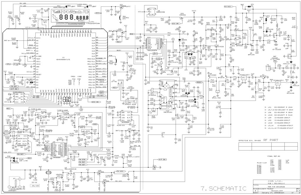
19 19 7. Annex: Circuit layouts and Schematic Diagram
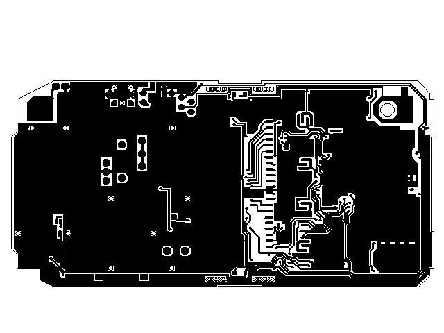
20 20
21 21 Copyright Albrecht Electronic GmbH & Jcom Ltd, Jan Albrecht Electronic GmbH Dovenkamp Lütjensee All service documents can be downloaded for service purpose from: Service-Hotline: (+49) Service-Fax: (+49)
22 1
Tectalk(FM) SERVICE MANUAL
 SERVICE MANUAL") Tectalk(FM) SERVICE MANUAL 2-WAY PORTABLE PMR 446 RADIO WITH FM BROADCAST RECEIVER Nov. 07. 2001 ALAN Electronics GmbH CONTENT 1. GENERAL 1.1 General 1.2 Characteristic 1.3 Composition 2. SPECIFICATION
Tectalk(FM) SERVICE MANUAL 2-WAY PORTABLE PMR 446 RADIO WITH FM BROADCAST RECEIVER Nov. 07. 2001 ALAN Electronics GmbH CONTENT 1. GENERAL 1.1 General 1.2 Characteristic 1.3 Composition 2. SPECIFICATION
Instruction Manual PMR-101TX. Private Mobile Radio. TTI Tech. 446MHz, 8 Channels
 PMR-101TX Instruction Manual Private Mobile Radio 446MHz, 8 Channels? 38 CTCSS Sub Tone? 8 Channels? VOX Mode? Scanning? Monitor? Key Pad Lock? Dual Watch? Auto Power Save Mode? Battery Status Indicator?
DC Instruction Manual. Professional FM Transceiver
 DC-1074 Professional FM Transceiver Instruction Manual Use of the citizen band radio service is licensed in Australia by ACMA Radiocommunications (Citizen Band Radio Stations) Class Licence and in New
THEORY OF OPERATION. TM308EUL for Cobra Nov 06,2006
 THEORY OF OPERATION TM308EUL for Cobra Nov 06,2006 This PLL controlled VHF marine mobile transceiver provides an accurate and stable multi-channel operation. The transceiver consists of 15 main sections
Owner s Manual PMR 446 Handheld transceiver G5
 Owner s Manual PMR 446 Handheld transceiver G5 Featuring 8 Channels 38 CTCSS codes VOX/Babymonitoring Display illumination Scan function Roger Beep Tone Index Accessories 4 Introduction 5 Controls and
Lava LP-4011-E P1 P2 USER MANUAL
 Lava LP-4011-E P1 P2 USER MANUAL Introduction Thank you for purchasing Lava LP-4011-E. Lava LP-4011-E is a PMR-product (Private Mobile Radio) that lets you talk to as many people you wish, as often as
FT-897 Alignment. Local Oscillator Adjustment. PLL Adjustment
 FT-897 Local Oscillator Adjustment Reference Frequency Adjustment a. Connect a frequency counter to TP1032. b. Adjust the trimmer capacitor (TC5001) for 67.875000MHz ±5Hz on the frequency counter. c. Connect
Model: TP380 User Manual
 Model: TP380 User Manual 1 UHF RADIO TRANSCEIVER MODEL: TP380 USER MANUAL INTRODUCTION Thank you for selecting the Oregon Scientific TP380 as your product of choice. This product is a portable, easy-to-use
Instruction Manual. Model: TX-446. Tech Private Mobile Radio (PMR)446MHz
446MHz") Instruction Manual Tech Private Mobile Radio (PMR)446MHz Model: TX-446 TTI TECH CO., LTD. Eundo Bldg, 737-19, Banpo-1dong, Seocho-ku, Seoul, Korea, 137-041 http://www.ttikorea.co.kr TABLE OF CONTENTS 1.
Instruction Manual Tech Private Mobile Radio (PMR)446MHz Model: TX-446 TTI TECH CO., LTD. Eundo Bldg, 737-19, Banpo-1dong, Seocho-ku, Seoul, Korea, 137-041 http://www.ttikorea.co.kr TABLE OF CONTENTS 1.
GETTING STARTED. Radio layout. LCD display with icons
 GETTING STARTED Radio layout LCD display with icons 1. Key lock button 2. Battery meter 3. Main channel indicator 4. Scan icon 5. Roger beep indicator 6. CTCSS sub-channel indicator 7. VOX indicator 1
Pair of PMR446 Two-Way Personal Radios Model: TP391
 Pair of PMR446 Two-Way Personal Radios Model: TP391 USER MANUAL MANUALE D USO MANUEL DE L UTILISATEUR BEDIENUNGSANLEITUNG MANUAL DE USUARIO MANUAL DO USUÁRIO HANDLEIDING BRUKSANVISNING P/N:086L004722-016
OWNER S MANUAL FRS RADIO
 OWNER S MANUAL FRS RADIO 21-1860 INTRODUCTION Your RadioShack FRS radio is a portable, easy-to-use, two-way radio that you can carry almost anywhere. Use it at shopping malls, amusement parks, sports events,
Preliminary Information (There will be updates)
") This Manual is provided by CBTricks.com Someone who wanted to help you repair your equipment put together this information. Cobra150GTL DX If you would like to help us put more manuals online support us.
This Manual is provided by CBTricks.com Someone who wanted to help you repair your equipment put together this information. Cobra150GTL DX If you would like to help us put more manuals online support us.
MAINTENANCE MANUAL TRANSMITTER/RECEIVER BOARD CMN-234A/B FOR MLSU141 & MLSU241 UHF MOBILE RADIO TABLE OF CONTENTS
 MAINTENANCE MANUAL TRANSMITTER/RECEIVER BOARD CMN-234A/B FOR MLSU141 & MLSU241 UHF MOBILE RADIO TABLE OF CONTENTS DESCRIPTION... 2 CIRCUIT ANALYSIS... 2 TRANSMITTER... 2 9-Voft Regulator... 2 Exciter...
MAINTENANCE MANUAL RF BOARD 19D901835G1 ( MHz) 19D901835G2 ( MHz) FOR MVS
 19D901835G2 ( MHz) FOR MVS") D MAINTENANCE MANUAL F BOAD 19D901835G1 (136-153 MHz) 19D901835G2 (150-174 MHz) FO MVS TABLE OF CONTENTS DESCIPTION............................................... Front Cover CICUIT ANALYSIS..............................................
D MAINTENANCE MANUAL F BOAD 19D901835G1 (136-153 MHz) 19D901835G2 (150-174 MHz) FO MVS TABLE OF CONTENTS DESCIPTION............................................... Front Cover CICUIT ANALYSIS..............................................
Frequency Coverage MHz RF Power Output 30W SSB / 9W AM/ 30W FM Dual Finals on Heat Sink Modes AM, FM, USB, LSB Microprocessor
 MAGNUM M-257 30W AM/ /FM/SSB 10--11 Meterr Mobile Trranscei ivverr n Prri iiccee: : US$ 250..00 eexx ssttoocckk JJaakkaarrttaa (Arrrri ( iivvi iinngg 2 d weeeekk iinn i Maarrcchh) ) SPECIFICATIONS Frequency
200GTL ALIGNMENT REVISION: 1.0 BURKE MODEL: 200GTL REVISION: 1.2 DATE: 02/14/06. Total Pages: 6 pages. Page:1 print date: 9/23/09
 ALIGNMENT PROCEDURE MODEL: 200GTL REVISION: 1.2 DATE: 02/14/06 PREPARED BY: BURKE Total Pages: 6 pages Page:1 print date: 9/23/09 1 TEST CONDITION: 200GTL ALIGNMENT INSTRUCTION 1.0. TEST TEMPERTAURE: 77
Receiver Adjustments
 ! -8-4!5 This Section details procedures for tuning and adjustment of T2000 series II radios. This is normally only required during product manufacture or after major servicing. The following topics are
OPERATOR S MANUAL KYODO WEST MODEL KG506 FULL-DUPLEX MOBILE. Preliminary
 OPERATOR S MANUAL KYODO WEST MODEL KG506 FULL-DUPLEX MOBILE Preliminary 1.0 INTRODUCTION Thank you for purchasing the KYODO WEST MODEL KG506 Full-Duplex Mobile Radio. This manual contains information to
ericssonz LBI-38640E MAINTENANCE MANUAL FOR VHF TRANSMITTER SYNTHESIZER MODULE 19D902780G1 DESCRIPTION
 MAINTENANCE MANUAL FOR VHF TRANSMITTER SYNTHESIZER MODULE 19D902780G1 TABLE OF CONTENTS Page DESCRIPTION........................................... Front Cover GENERAL SPECIFICATIONS...................................
Content. Maintenance. Features ENGLISH. 1 transceiver 1 antenna 1 battery pack 1 belt clip 1 fast desktop charger User manual
 ENGLISH Content 1 transceiver 1 antenna 1 battery pack 1 belt clip 1 fast desktop charger User manual If any items are missing, contact your dealer. Maintenance Your Two Way Radio is an electronic product
ALAN 777 PMR 446 Radio Set User manual
 ALAN 777 PMR 446 Radio Set User manual The all new ALAN 777 represents the very latest and most advanced technology currently available on the PMR446 and LPD market. With its stylish lines and modern design,
PMR446 Radio Instruction Manual
 Tectalk PRO PMR446 Radio Instruction Manual Thank you for purchasing this radio. All our products are built to offer excellent value by combining advanced features, great design and manufacturing quality.
Preliminary Users Manual, Telex SAFE-1000 System.
 Preliminary Users Manual, Telex SAFE-1000 System. Telex Model SAFE-1000 Wireless Microphone Receiver. Telex Model SAFE-WT Wireless Beltpack Transmitter. Telex Model SAFE-HT Wireless Handheld Transmitter.
MAINTENANCE MANUAL FOR MHz PERSONAL TWO-WAY FM RADIO COMBINATION
 MAINTENANCE MANUAL FOR 896-941 MHz PERSONAL TWO-WAY FM RADIO COMBINATION TABLE OF CONTENTS Page INTRODUCTION................................................... 1 PHASE 1: RADIO SECTION TROUBLSHOOTING Functional
32 CHANNEL SELECTABLE CH MHZ DOWN VOLUME
 KARAOKE Professional UHF Wireless Microphone System VM-92U Operating Instructions UHF Frequency 64 Selectable Better Music Builder UHF MIC WIRELESS SYSTEM VM-92U 32 CHANNEL SELECTABLE 248 13.10 CH MHZ
AUDIOVOX GMRS4WM Owner s/installation Manual
 AUDIOVOX GMRS4WM Owner s/installation Manual GMRS (General Mobile Radio Service) Wall Mount Charger Patent Pending www.asaelectronics.com WARNING Replacement or substitution of transistors, diodes, or
HIGH-POWER, REPORTAGE WIRELESS-MICROPHONE SYSTEM RPU300-UU - FULL-DUPLEX PORTABLE TRANSCEIVER UHF Main-transmitter - UHF Communications-receiver
 HIGH-POWER, REPORTAGE WIRELESS-MICROPHONE SYSTEM RPU300-UU - FULL-DUPLEX PORTABLE TRANSCEIVER UHF Main-transmitter - UHF Communications-receiver Main-transmitter section Communication-receiver section
ANALOG COMMUNICATION
 ANALOG COMMUNICATION TRAINING LAB Analog Communication Training Lab consists of six kits, one each for Modulation (ACL-01), Demodulation (ACL-02), Modulation (ACL-03), Demodulation (ACL-04), Noise power
HIGH-POWER, REPORTAGE WIRELESS-MICROPHONE SYSTEM RPU300 - FULL-DUPLEX PORTABLE TRANSCEIVER VHF Main-transmitter - UHF Communications-receiver
 HIGH-POWER, REPORTAGE WIRELESS-MICROPHONE SYSTEM RPU300 - FULL-DUPLEX PORTABLE TRANSCEIVER VHF Main-transmitter - UHF Communications-receiver Main-transmitter section Communication-receiver section VHF
Maintenance Manual. MTD SERIES 900 MHz, 10-WATT, DATA ONLY MOBILE RADIO. Mobile Communications LBI TABLE OF CONTENTS
 Mobile Communications MTD SERIES 900 MHz, 10-WATT, DATA ONLY MOBILE RADIO TABLE OF CONTENTS RF BOARD............................... LBI-38545 AUDIO BOARD............................ LBI-38546 LOGIC BOARD............................
INSTALLATION AND OPERATION GUIDE
 VHF Marine Radio RT-311 INSTALLATION AND OPERATION GUIDE Navicom plaisance: Z.A. des Boutries, 78700 Conflans Ste Honorine Tel: 01.39.72.19.90 Fax: 01.39.19.28.98 Navicom Pro: 3, rue J. Cugnot, Z.A.C Petit
User Manual. Specifications...3. Control and Operation Microphone...8. Installation...9. Installation of Main Unit...9
 Contents Specifications...3 Control and Operation...4-7 Microphone...8 Installation...9 Installation of Main Unit...9 Antenna Installation...9 Operational test...9 Frequency Bands Table...10 Frequency
ID-5100 User Evaluation & Test Report
 ID-5100 User Evaluation & Test Report By Adam Farson VA7OJ/AB4OJ Iss. 1, August 13, 2014. Part I: Brief User Evaluation. Introduction: This report describes the evaluation and lab test of ID-5100 S/N 05001175.
TLKR T60 OWNER'S MANUAL EN DE FR IT ES PR NL DA NO TU PL SV RU
 TLKR T60 OWNER'S MANUAL EN DE FR IT ES PR NL DA NO TU PL SV RU SF 1 PRODUCT SAFETY AND RF EXPOSURE FOR PORTABLE TWO-WAY RADIOS! Caution ATTENTION! Before using this product, read the RF energy awareness
MAINTENANCE MANUAL RF BOARD 19D902243G4 ( MHz) 19D902243G5 ( MHz) 19D902243G6 ( MHz) FOR MVS
 19D902243G5 ( MHz) 19D902243G6 ( MHz) FOR MVS") LI-38258D IC DATA MAINTENANCE MANUAL F OAD 19D902243G4 (403-440 MHz) 19D902243G5 (440-470 MHz) 19D902243G6 (470-512 MHz) FO MVS OPEATIONAL AMPLIFIE 19A701789P2 QUAD ILATEAL SWITCH (U202) 19A700029P44 TALE
LI-38258D IC DATA MAINTENANCE MANUAL F OAD 19D902243G4 (403-440 MHz) 19D902243G5 (440-470 MHz) 19D902243G6 (470-512 MHz) FO MVS OPEATIONAL AMPLIFIE 19A701789P2 QUAD ILATEAL SWITCH (U202) 19A700029P44 TALE
LBI-31564A. Mobile Communications. DELTA - SX MHz RADIO COMBINATIONS (NEGATIVE GROUND ONLY) Maintenance Manual
 Maintenance Manual") A Mobile Communications DELTA - SX 136-174 MHz RADIO COMBINATIONS (NEGATIVE GROUND ONLY) Maintenance Manual TABLE OF CONTENTS MILITARY AND SYSTEM SPECIFICATIONS................................. 2-3 COMBINATION
A Mobile Communications DELTA - SX 136-174 MHz RADIO COMBINATIONS (NEGATIVE GROUND ONLY) Maintenance Manual TABLE OF CONTENTS MILITARY AND SYSTEM SPECIFICATIONS................................. 2-3 COMBINATION
TS-590S ADJUSTMENT. Updating the Firmware. Required Test Equipment. Preparation
 Updating the Firmware The firmware of the main MCU and DSP can be updated using the TS590 Update update software. Update the firmware according to the procedure displayed in update software. Refer to the
Owner s Manual. GMRS/Weather Model: GMRS-2000 General Mobile Radio Service Base Station With NOAA Weather Alert
 GMRS/Weather Model: GMRS-2000 General Mobile Radio Service Base Station With NOAA Weather Alert Owner s Manual Customer Service/Service 1-800-290-6650 CAUTION NEVER ATTEMPT TO CHARGE ALKALINE OR DRY CELL
IC-400pro - RADIOAFICION.COM
 PROCEDURES IC-400pro - 5- PREPARATION When you adjust the contents on pages 5-5 and 5-6, SOFT- WARE, the optional CS-400PRO ADJ SOFTWARE (Rev..0 or later), *OPC- JIG CABLE (modified OPC- CLONING CABLE;
Maintenance Manual. ORION UHF (Dual Bandwidth) SCAN AND SYSTEM MOBILE RADIO. ericssonz LBI TABLE OF CONTENTS
 SCAN AND SYSTEM MOBILE RADIO. ericssonz LBI TABLE OF CONTENTS") Maintenance Manual ORION UHF (Dual Bandwidth) SCAN AND SYSTEM MOBILE RADIO TABLE OF CONTENTS Synthesizer/Receiver/Exciter....... LBI-39163 Power Amplifier.............. LBI-39164 PA Interface................
Maintenance Manual ORION UHF (Dual Bandwidth) SCAN AND SYSTEM MOBILE RADIO TABLE OF CONTENTS Synthesizer/Receiver/Exciter....... LBI-39163 Power Amplifier.............. LBI-39164 PA Interface................
Basic Transceiver tests with the 8800S
 The most important thing we build is trust ADVANCED ELECTRONIC SOLUTIONS AVIATION SERVICES COMMUNICATIONS AND CONNECTIVITY MISSION SYSTEMS Basic Transceiver tests with the 8800S Basic Interconnects Interconnect
RL /430MHZ DUAL BAND FM TRANSCEIVER OPERATION INSTRUCTION
 RL-502 144/430MHZ DUAL BAND FM TRANSCEIVER OPERATION INSTRUCTION RoHS Table of Contents Packing List...1 Cautions...2 Parts Name & Functions...3 Fitting & Removing the Battery Pack...4 Installation the
Improved performance and mobility for more applications. Delivering a new standard for high performance in complete wireless microphone systems, TOA
 Improved perfmance and mobility f me applications. Delivering a new standard f high perfmance in complete wireless microphone systems, TOA provides a full range of wireless microphones optimized f general
ALAN HP 106 SERVICE MANUAL
 ALAN HP 106 SERVICE MANUAL HP106 Service Manual ALAN HP106 Portable VHF Transceiver Service Manual Copyright 2003 by CTE International Italy; all rights reserved Page 1 of 12 HP106 Service Manual Contents
GMRS Owner s. General Mobile Radio Service (GMRS) Model : of 24. Customer Service Released:
 Model : of 24. Customer Service Released:") General Mobile Radio Service (GMRS) Model : GMRS-1200 Owner s Manual EMG CTC ID OUT OF RANGE MODE SCAN EMG Customer Service 1-800-290-6650 Released: 2-1-02. 1 of 24 CAUTIONS NEVER ATTEMPT TO CHARGE ALKALINE
General Mobile Radio Service (GMRS) Model : GMRS-1200 Owner s Manual EMG CTC ID OUT OF RANGE MODE SCAN EMG Customer Service 1-800-290-6650 Released: 2-1-02. 1 of 24 CAUTIONS NEVER ATTEMPT TO CHARGE ALKALINE
The New ilive series of AMC Wireless systems
 The New ilive series of AMC Wireless systems Created for active musician and presenters who also manage their own sound, AMC ilive improves your performance and simplifies your setup. Innovations such
PPA 377. Personal PA FM Listening System FM SPECIFICATION DATA. System Includes:
 FM SPECIFICATION DATA Churches Schools Auditoriums Conference Rooms Theaters PPA 377 Personal PA FM Listening System The PPA 377 features the T35 high performance transmitter: powerful microprocessor,
MIDLAND (TEAM MEMBER) RADIO-RELATED INFORMATION OPERATION OF THE WOUXAN UVA-1 OR DB16X IC RADIOS
 RADIO-RELATED INFORMATION OPERATION OF THE WOUXAN UVA-1 OR DB16X IC RADIOS") MIDLAND TEAM MEMBER) RADIO-RELATED INFORMATION When your radio is to be stored for an extended period, you should remove the batteries so that they will not corrode and damage the radio. You may need to
MIDLAND TEAM MEMBER) RADIO-RELATED INFORMATION When your radio is to be stored for an extended period, you should remove the batteries so that they will not corrode and damage the radio. You may need to
Maintenance Manual TRANSMITTER/RECEIVER BOARD CMN-233 FOR MLSH041
 Maintenance Manual TRANSMITTER/RECEIVER BOARD CMN-233 FOR MLSH041 TABLE OF CONTENTS Page DESCRIPTION... 2 CIRCUIT ANALYSIS... 2 Transmitter... 2 9-volt Regulator... 2 Exciter... 2 40-Watt PA... 2 Antenna
USER'S MANUAL UHF BAND
 USER'S MANUAL I UHF BAND MICROPHONE SYSTEM I 1440-8120-01 NOTE. HmmHmmmJ i... 1 FCC Statement MICROPHONE SYSTEM Table of Contents 1. Introduction......... 1 2. Safety... 1 3. Environment... 1 4. Wireless
Midland 248XL I NSTRUCTION GUI DE
 Midland 248XL I NSTRUCTION GUI DE INDEX Introduction...2 Function and location of the controls...3 Installation...7 Power supply...7 Installing an antenna...7 How to use your Midland 248XL...8 Frequency
RU210. Dual Multi-UHF Wireless System. Item ref: UK, UK User Manual. Version 1.0
 RU210 Dual Multi-UHF Wireless System Item ref: 171.970UK, 171.971UK User Manual Version 1.0 Caution: Please read this manual carefully before operating Damage caused by misuse is not covered by the warranty
i4088a INSTRUCTION MANUAL FRS UHF FM TRANSCEIVER
 INSTRUCTION MANUAL FRS UHF FM TRANSCEIVER i4088a This device complies with Part 15 of the FCC rules. Operation is subject to the following two conditions: (1) This device may not cause harmful interference,
PMR-121TX / PMR-121TX-2CH PMR 446 TRANSCEIVER
 PMR-121TX PMR-121TX / PMR-121TX-2CH PMR 446 TRANSCEIVER www.ttikorea.co.kr Speaker Microphone/ Charger Jack 1 5 Antenna Push-To Talk Button 2 Down Button 3 Microphone 4 6 LCD Display Up Button 8 Mode/Keypad
INSTRUCTION MANUAL PMR446 FM TRANSCEIVER. i4088sr
 INSTRUCTION MANUAL PMR446 FM TRANSCEIVER i4088sr FOREWORD Thank you for purchasing the IC-4088SR PMR446 FM transceiver. This PMR (Private Mobile Radio) FM transceiver meets the European PMR specification
Circuit Description. Receive Signal Path. CTCSS Operation. S-Meter. RX PLL & VCO Circuit. Squelch Control. RPP Programming Software Instruction
 RPP Programming Software Instruction VXR-5000 Receive Signal Path ~com.ing RF from the RX antenna jack is dehvered to the RX Unit and passes through the bandpass filter consisting of coils L4002, L4003
MASTR II BASE STATION MHz RECEIVER IF/AUDIO/SQUELCH & RF ASSEMBLY (25 khz/12.5 khz CHANNEL SPACING) Maintenance Manual LBI-38506A
 Maintenance Manual LBI-38506A") A Mobile Communications MASTR II BASE STATION 806-824 MHz RECEIVER IF/AUDIO/SQUELCH & RF ASSEMBLY (25 khz/12.5 khz CHANNEL SPACING) TABLE OF CONTENTS RF ASSEMBLY, MIXER AND IF FILTER BOARD...... LBI-30482
A Mobile Communications MASTR II BASE STATION 806-824 MHz RECEIVER IF/AUDIO/SQUELCH & RF ASSEMBLY (25 khz/12.5 khz CHANNEL SPACING) TABLE OF CONTENTS RF ASSEMBLY, MIXER AND IF FILTER BOARD...... LBI-30482
MAINTENANCE MANUAL AUDIO BOARDS 19D902188G1, G2 & G3
 B MAINTENANCE MANUAL AUDIO BOARDS 19D902188G1, G2 & G3 TABLE OF CONTENTS Page Front Cover DESCRIPTION............................................... CIRCUIT ANALYSIS............................................
Yaesu FT-25R 2-Meter Handheld Transceiver
 Yaesu FT-25R 2-Meter Handheld Transceiver Reviewed by Dan Wall, W1ZFG ARRL LoTW Administration w1zfg@arrl.org The latest entry into the field of small, inexpensive handhelds is the Yaesu FT-25R. This is
G11 I N S T R U C T I O N G U I D E. Midland PMR446 Transceiver
 PMR446 Transceiver G11 I N S T R U C T I O N G U I D E Midland PMR446 Transceiver MIDLAND G11 PMR446 Transceiver Thanks for choosing Midland! G11 is a portable transceiver that is free use in almost all
3 T856/857 Initial Tuning & Adjustment
 M850-00 T856/857 Initial Tuning & Adjustment C3.1 3 T856/857 Initial Tuning & Adjustment The following section describes the full tuning and adjustment procedure and provides information on: channel programming
Owner s Manual Manuel d'utilisation
 General Mobile Radio Service (GMRS) Model/Modèle : GMRS-1525 Owner s Manual Manuel d'utilisation MODE SCAN EMG Customer Service/ Service à la clientèle 1-800-290-6650 CAUTIONS NEVER ATTEMPT TO CHARGE ALKALINE
ALAN 48P 4W SMT MULTI CIRCUIT DESCRIPTION
 ALAN 48P 4W SMT MULTI CIRCUIT DESCRIPTION INTRODUCTION 1.Multi BAND:Italy,Italy-34CH, Germany-80CH, Germany,Germany-80CH-40CH-4W Spain, Europe, CEPT, England, England-CEPT, Poland,Poland-400CH, Russi a-400ch,france,sweden
evolution wireless G4 ew 300 G4-Base SK-RC Bodypack Base Set
 1/7 Best choice for your business, top of the class in education. The G4 300 Series uses the power of an increased switching bandwidth of up to 88 MHz. New frequency ranges allow to operate multi-channel
Handheld UHF CB Radio
 Handheld UHF CB Radio Instruction Manual Model: AUHR-014 Customer Helpline 1300 886 649 Welcome Congratulations on choosing to buy an ONIX product. All products brought to you by Onix are manufactured
BX SERIES HANDHELD RADIOS COMMERCIAL INSTRUCTION MANUAL BX SERIES HANDHELD INSTRUCTION MANUAL PAGE 1. Instruction manual includes models:
 COMMERCIAL BX SERIES HANDHELD RADIOS Instruction manual includes models: BX710 BX720 BX730 INSTRUCTION MANUAL BX SERIES HANDHELD INSTRUCTION MANUAL PAGE 1 WARNING - SAFETY INFORMATION The BX Series are
INSTRUCTION MANUAL LPD FM HANDHELD TRANSCEIVER. i4008e
 INSTRUCTION MANUAL LPD FM HANDHELD TRANSCEIVER i4008e FOREWORD Thank you for purchasing the IC-4008E LPD (Low Power Device) FM transceiver. This LPD FM transceiver meets the European LPD specification
INSTRUCTION MANUAL MODEL 2779 SUBCARRIER MODULATOR
 INSTRUCTION MANUAL MODEL 2779 SUBCARRIER MODULATOR Data, drawings, and other material contained herein are proprietary to Cross Technologies, Inc., and may not be reproduced or duplicated in any form without
CS2010 AND CS2011 ALIGNMENT REFERENCE MANUAL FM HANDHELD TRANCEIVER. Connect Systems Incorporated 1802 Eastman Ave., Suite 116 Ventura CA 93003
 CS2010 AND CS2011 ALIGNMENT REFERENCE MANUAL FM HANDHELD TRANCEIVER Connect Systems Incorporated 1802 Eastman Ave., Suite 116 Ventura CA 93003 Version 1.01 Copyright 2009 by Connect Systems Incorporated
CON NEX HP. OWNER'S MANUAL Full Channel AM/FM Amateur Mobile Transceiver TABLE OF CONTENTS TUNING THE ANTENNA FOR OPTIMUM S.W.R..
 TABLE OF CONTENTS PAGE SPECIFICATIONS... 2 INSTALLATION... 3 LOCATION... 3 CON NEX - 4300HP MOUNTING THE RADIO... 3 IGNITION NOISE INTERFERENCE... 4 ANTENNA... 4 TUNING THE ANTENNA FOR OPTIMUM S.W.R..
XU/XV-100 Series User Manual
 XU/XV-100 Series User Manual This device complies with Part 15 of FCC Rules. Operation is subject to the following two conditions: This device may not cause harmful interference, and 2) This device must
DC-1122 Compact 5W UHF CB Radio
 DC-1122 Compact 5W UHF CB Radio Instruction Manual Introduction! NOTE Use of the citizen band radio service is licensed in Australia by ACMA Radio communications (Citizen Band Radio Stations) Class Licence
UH043SX-2NB. UHF CB Transceiver. For more exciting new products please visit our website: Australia: New Zealand:
 UH043SX-2NB UHF CB Transceiver For more exciting new products please visit our website: Australia: www.uniden.com.au New Zealand: www.uniden.co.nz Controls & Indicators Included in your Package UH043SX-NB
Single Channel Radio Mic System USER MANUAL. WMU-116-H (Hand Held) WMU-116-B (Belt Pack) Single Channel Radio Mic System
 WMU-116-B (Belt Pack) Single Channel Radio Mic System") Single Channel Radio Mic System USER MANUAL WMU-116-H (Hand Held) WMU-116-B (Belt Pack) Single Channel Radio Mic System Welcome Thank you for choosing Hill Audio for your sound system. To make sure that
Single Channel Radio Mic System USER MANUAL WMU-116-H (Hand Held) WMU-116-B (Belt Pack) Single Channel Radio Mic System Welcome Thank you for choosing Hill Audio for your sound system. To make sure that
evolution wireless G4 ew 500 BOOM G4 Pro Camera Plug-on Transmitter set
 1/6 The professional s choice for broadcast quality sound Providing the highest flexibility for your video sound and field recording applications. A robust wireless microphone system that offers ultimate
Langton House, 19 Village Street, Harvington, Worcestershire. WR11 8NQ Tel: Fax: RTB5211 UHF FULL DUPLEX BASE STATION
 Langton House, 19 Village Street, Harvington, Worcestershire. WR11 8NQ Tel:- 01789 777040 Fax:- 01789 881330 RTB5211 UHF FULL DUPLEX BASE STATION OPERATORS MANUAL Print Date 31/10/2008 Page 1 of 10 E2057-00MA-01.doc
ERICSSONZ LBI-39123A. MAINTENANCE MANUAL FOR 21.4 MHz RECEIVER IF MODULE 12.5/25 khz CHANNEL SPACING 19D902783G7 DESCRIPTION TABLE OF CONTENTS
 A MAINTENANCE MANUAL FOR 21.4 MHz 12.5/25 khz CHANNEL SPACING 19D902783G7 TABLE OF CONTENTS Page DESCRIPTION............................................ Front Cover GENERAL SPECIFICATIONS....................................
Commercial Analogue Series VX-450, VX-4600 and VXR-9000
 Commercial Analogue Series VX-450, VX-4600 and VXR-9000 Meets the following standards: AS/NZS4295, ISO9001 and ISO4001 Commercial Analogue Series VX-450, VX-4600 and VXR-9000 Durable on-the-job responsiveness
music Miniature instruments wireless system Instruction Manual
 Miniature music instruments wireless system Instruction Manual 1. Important Caution Always make all connections before plugging the unit into an AC power outlet. Do not leave the devices in a place with
CS3000 ALIGNMENT REFERENCE MANUAL FM HANDHELD TRANCEIVER. Connect Systems Incorporated 1802 Eastman Ave., Suite 116 Ventura CA Version 1.
 CS3000 ALIGNMENT REFERENCE MANUAL FM HANDHELD TRANCEIVER Connect Systems Incorporated 1802 Eastman Ave., Suite 116 Ventura CA 93003 Version 1.00 Copyright 2010 by Connect Systems Incorporated TABLE OF
User Manual. ilive 2 Wireless microphone system
 User Manual ilive 2 Wireless microphone system Safety instructions When using this electronic device, basic precautions should always be taken, including the following: 1 Read all instructions before using
1. Antenna 2. Belt Clip 3. Battery compartment with Battery 4. Charger connector 5. Battery compartment cover latch 6. Push to Talk button 7.
 DC-1068 DC-1069 1. Antenna 2. Belt Clip 3. Battery compartment with Battery 4. Charger connector 5. Battery compartment cover latch 6. Push to Talk button 7. Call / Monitor button 8. Speaker Grill 9.
1. Antenna 2. Belt Clip 3. Battery compartment with Battery 4. Charger connector 5. Battery compartment cover latch 6. Push to Talk button 7.
 DC-1068 DC-1069 1. Antenna 2. Belt Clip 3. Battery compartment with Battery 4. Charger connector 5. Battery compartment cover latch 6. Push to Talk button 7. Call / Monitor button 8. Speaker Grill 9. LCD
S5101 Handheld Radio Communication Analyzer
 is the ideal radio tester for laboratory, production, service and maintenance use. It combines radio frequency emission, reception analysis, audio source, analyzer, etc. all into one unit. It can measure
evolution wireless G4 ew 512 P G4 Pro Camera Lavalier MKE 2 Set
 1/6 The professional s choice for broadcast quality sound Providing the highest flexibility for your video sound and field recording applications. A robust wireless microphone system that offers ultimate
Professional UHF Rechargeable Wireless Microphone System POWER ON/OFF BATTERY CHARGE. Green Light (Full) Better Music Builder DOWN VOLUME
 Better Music Builder DOWN VOLUME") Green Light (Full) KARAOKE Professional UHF Rechargeable Wireless Microphone System VM-93C Operating Instructions UHF Frequency 64 Selectable POWER ON/OFF CHARGE Better Music Builder VM-93C CHARGER UHF
Green Light (Full) KARAOKE Professional UHF Rechargeable Wireless Microphone System VM-93C Operating Instructions UHF Frequency 64 Selectable POWER ON/OFF CHARGE Better Music Builder VM-93C CHARGER UHF
DRF2018A113 Low Power Audio FM Transmitter Module V1.00
 DRF2018A113 Low Power Audio FM Transmitter Module V1.00 Features Audio PLL transmitter module 433/868/915Mhz ISM frequency band 13dBm Max. output power Phase noise: -94dBc/Hz Multiple channels Audio response:55~22khz
TX670 POCKET SIZE UHF CB RADIO INSTRUCTION MANUAL 2 WATT HANDHELD. TX670 Instruction Manual Page 1
 TX670 POCKET SIZE 2 WATT HANDHELD UHF CB RADIO INSTRUCTION MANUAL TX670 Instruction Manual Page 1 Warning: Safety Information The TX670 is a radio frequency transmitting device. When transmitting, keep
TWS 16 BT UHF wireless system. user manual
 TWS 16 BT UHF wireless system user manual Musikhaus Thomann e.k. Treppendorf 30 96138 Burgebrach Germany Telephone: +49 (0) 9546 9223-0 email: info@thomann.de Internet: www.thomann.de 09.03.2012 Table
UHF Wireless Microphone System
 PDWM1902 PDWM1904 PDWM3375 PDWM3378 PDWM3400 UHF Wireless Microphone System SYSTEM TYPE The Vocal Artist-UHF is a hand-held system designed for singers who desire the high quality microphones and the freedom
TWS 16 PT UHF wireless system. user manual
 TWS 16 PT UHF wireless system user manual Musikhaus Thomann Thomann GmbH Hans-Thomann-Straße 1 96138 Burgebrach Germany Telephone: +49 (0) 9546 9223-0 E-mail: info@thomann.de Internet: www.thomann.de 17.11.2015,
OWNER S MANUAL 311DRH 311DR 221R 211R 200R 31LT 31IT 32BT 32IT 31HT 31XT
 VHF PERFORMANCE SERIES WIRELESS MICROPHONE SYSTEMS OWNER S MANUAL 311DRH 311DR 221R 211R 200R 31LT 31IT 32BT 32IT 31HT 31XT AZDEN CORPORATION P.O. Box 10-147 New Hyde Park Road Franklin Square, NY 11010
VHF Transceiver AR6201
 VHF Transceiver AR6201 Operating Instructions Issue 2 / October 2010 Article No. 0618.764-071 Becker Flugfunkwerk GmbH Baden-Airpark B 108 77836 Rheinmünster Germany Telefon / Telephone +49 (0) 7229 /
evolution wireless G4 ew 112 P G4 Camera Lavalier ME 2 Set ew 122 P G4 Camera Lavalier ME 4 Set
 1/7 A broadcast quality sound solution. Providing the highest flexibility for your video sound and field recording applications. A robust wireless microphone system that offers excellent sound quality,
SEIKAKU TECHNICAL GROUP LIMITED
 SEIKAKU TECHNICAL GROUP LIMITED TOPP PRO NF08 / TMW-9R/T/P TOPP PRO_V.0 PE00 0.8Kg/ 0g A A A 8 MAR.0.00 PHFWA0-000000,A, PGBSC00-0009008,A, R User's Manual TMW-9R/T/P WIRELESS MICROPHONE SYSTEM TMW-9P
RF/IF Terminology and Specs
 RF/IF Terminology and Specs Contributors: Brad Brannon John Greichen Leo McHugh Eamon Nash Eberhard Brunner 1 Terminology LNA - Low-Noise Amplifier. A specialized amplifier to boost the very small received
Owner s Manual For Models G-225 & G-227 GMRS/FRS Radio
 Owner s Manual For Models G-225 & G-227 GMRS/FRS Radio FEATURING 22 Channels 38 CTCSS codes VOX Monitor function Call Alert Back-Lit LCD Vibrate Alert (G-227 Only) Scan Roger Beep Tone This device complies
WIRELESS MICROPHONE. Audio in the ISM band
 WIRELESS MICROPHONE udio in the ISM band Ton Giesberts When the ISM frequency band was made available in Europe for audio applications, Circuit Design, a manufacturer of professional RF modules, decided
User s Guide. 1200URX/AB 1200URX/VM 1200URX/Si 1200BT 1200XT ENHANCED BROADCAST PERFORMANCE UHF WIRELESS SYSTEM
 SPECIFICATIONS 1200URX/AB - 1200URX/Si - 1200URX/VM RF Carrier Frequency Range 188 steps ~ 638.125-661.875 MHz MicroComputer Controlled PLL Synth. Noise Reduction Expander (THAT) Effective Operating Range