NAVAL POSTGRADUATE SCHOOL THESIS
|
|
|
- Bryce Day
- 6 years ago
- Views:
Transcription

1 NAVAL POSTGRADUATE SCHOOL MONTEREY, CALIFORNIA THESIS NPS-SCAT: A CUBESAT COMMUNICATIONS SYSTEM DESIGN, TEST, AND INTEGRATION by Matthew P. Schroer June 2009 Thesis Advisor: Second Reader: James H. Newman Terry E. Smith Approved for public release; distribution is unlimited
2 THIS PAGE INTENTIONALLY LEFT BLANK
3 REPORT DOCUMENTATION PAGE Form Approved OMB No Public reporting burden for this collection of information is estimated to average 1 hour per response, including the time for reviewing instruction, searching existing data sources, gathering and maintaining the data needed, and completing and reviewing the collection of information. Send comments regarding this burden estimate or any other aspect of this collection of information, including suggestions for reducing this burden, to Washington headquarters Services, Directorate for Information Operations and Reports, 1215 Jefferson Davis Highway, Suite 1204, Arlington, VA , and to the Office of Management and Budget, Paperwork Reduction Project ( ) Washington DC AGENCY USE ONLY (Leave blank) 2. REPORT DATE 3. REPORT TYPE AND DATES COVERED June 2009 Master s Thesis 4. TITLE AND SUBTITLE NPS-SCAT: A CubeSat 5. FUNDING NUMBERS Communications System Design, Test, and Integration 6. AUTHOR(S) Schroer, Matthew P. 7. PERFORMING ORGANIZATION NAME(S) AND ADDRESS(ES) Naval Postgraduate School Monterey, CA SPONSORING /MONITORING AGENCY NAME(S) AND ADDRESS(ES) N/A 8. PERFORMING ORGANIZATION REPORT NUMBER 10. SPONSORING/MONITORING AGENCY REPORT NUMBER 11. SUPPLEMENTARY NOTES The views expressed in this thesis are those of the author and do not reflect the official policy or position of the Department of Defense or the U.S. Government. 12a. DISTRIBUTION / AVAILABILITY STATEMENT 12b. DISTRIBUTION CODE Approved for public release; distribution is unlimited 13. ABSTRACT (maximum 200 words) Telemetry, tracking, and command (TT&C) systems on traditional small satellites have advanced significantly in capacity, throughput, and complexity over the last several decades. The CubeSat community is in need of similar advancements. The Naval Postgraduate School Solar Cell Array Tester (NPS-SCAT) seeks to provide the foundation for advances in future iterations of CubeSats at NPS. This thesis explains the design, test, and integration of a full TT&C sub-system for NPS-SCAT. The satellite will have two TT&C systems that provide full telemetry for the experiment through a primary communications channel and secondary telemetry through an amateur band beacon. The thesis explains the development of the concept of operations for the satellite that drove the data requirements provided by the TT&C system. The thesis also explains the testing procedures of the transceiver and the design, test, and integration of the primary and secondary antennas. Finally the thesis explains the frequency licensing process through the Navy-Marine Corps Spectrum Center and the Federal Communications Commission. 14. SUBJECT TERMS Satellite, CubeSat, NPS-SCAT, solar cell tester, communications, antenna patch, dipole antenna, beacon, TT&C, frequency coordination, Navy-Marine Corps Spectrum Center 17. SECURITY CLASSIFICATION OF REPORT Unclassified 18. SECURITY CLASSIFICATION OF THIS PAGE Unclassified 19. SECURITY CLASSIFICATION OF ABSTRACT Unclassified 15. NUMBER OF PAGES PRICE CODE 20. LIMITATION OF ABSTRACT NSN Standard Form 298 (Rev. 2-89) Prescribed by ANSI Std UU i
4 THIS PAGE INTENTIONALLY LEFT BLANK ii
5 Approved for public release; distribution is unlimited NPS-SCAT: A CUBESAT COMMUNICATIONS SYSTEM DESIGN, TEST, AND INTEGRATION Matthew P. Schroer Captain, United States Marine Corps B.S., United States Naval Academy 2000 Submitted in partial fulfillment of the requirements for the degree of MASTERS OF SCIENCE IN SYSTEMS TECHNOLOGY (COMMAND, CONTROL, AND COMMUNICATION (C3)) and MASTER OF SCIENCE IN SPACE SYSTEMS OPERATIONS from the NAVAL POSTGRADUATE SCHOOL June 2009 Author: Matthew Patrick Schroer Approved by: James H. Newman Thesis Advisor Terry E. Smith Second Reader Dan C. Boger Chairman, Department of Information Sciences Rudolph Panholzer Chairman, Space Systems Academic Group iii
6 THIS PAGE INTENTIONALLY LEFT BLANK iv
7 ABSTRACT Telemetry, tracking, and command (TT&C) systems on traditional small satellites have advanced significantly in capacity, throughput, and complexity over the last several decades. The CubeSat community is in need of similar advancements. The Naval Postgraduate School Solar Cell Array Tester (NPS-SCAT) seeks to provide the foundation for advances in future iterations of CubeSats at NPS. This thesis explains the design, test, and integration of a full TT&C sub-system for NPS-SCAT. The satellite will have two TT&C systems that provide full telemetry for the experiment through a primary communications channel and secondary telemetry through an amateur band beacon. The thesis explains the development of the concept of operations for the satellite that drove the data requirements provided by the TT&C system. The thesis also explains the testing procedures of the transceiver and the design, test, and integration of the primary and secondary antennas. Finally, the thesis explains the frequency licensing process through the Navy-Marine Corps Spectrum Center and the Federal Communications Commission. v
8 THIS PAGE INTENTIONALLY LEFT BLANK vi
9 TABLE OF CONTENTS I. INTRODUCTION...1 A. THE GROWTH OF THE CUBESAT COMMUNITY...1 B. THE NAVAL POSTGRADUATE SCHOOL SMALL SATELLITE PROGRAM...2 C. THE NAVAL POSTGRADUATE SCHOOL CUBESAT PROGRAM...3 D. A BRIEF HISTORY OF CUBESAT COMMUNICATIONS SYSTEMS Pletsak Launch: June 30, Pletsak Launch: October 27, Baikonur, Kazakhstan: July Baikonur, Kazakhstan: April Satish Dhawan Space Centre, India: April 28, Separate Launches: CUTE APD and GeneSat Wallops, Maryland: June E. FUTURE CUBESAT COMMUNICATIONS SYSTEMS...13 II. SOLAR CELL ARRAY TESTER COMMUNICATIONS SYSTEM REQUIREMENTS...17 A. DATA REQUIREMENTS Data Overview Solar Measurement System Clyde-Space 1U Electrical Power Subsystem Temperature Sensors FM430 Flight Module...22 B. SCAT CONCEPT OF OPERATIONS Overview Start-Up Operations Normal Operations...24 a. Transmission Mode...25 b. Sun Mode...25 c. Eclipse Mode...28 d. Beacon Mode...28 C. POWER REQUIREMENTS Primary Radio Beacon...30 III. RADIO DEVELOPMENT...33 A. PRIMARY TT&C LINK Basis for Radio Selection MHX 2420 Specification Primary Radio Link Budget...35 a. Propagation Path Length...36 b. Free Path Space Loss...39 vii
10 c. Transmitting and Receiving Communications System Characteristics...39 d. Energy per Bit versus Noise Radio Characterization and Testing...45 a. Current Draw Testing...45 b. Sensitivity Testing...53 c. Setting and Configuration Testing...56 B. BEACON Specifications Link Budget Beacon Characterization and Testing...59 C. OTHER RADIO TESTING Field Testing...60 a. First Field Test...60 b. Test Antenna...60 c. Additional Planned Field Testing Maximum Data Rate Testing Doppler Shift and Path Delay Considerations..66 D. RECOMMENDED PRIMARY RADIO CONFIGURATIONS Arbitrary Radio Settings Radio to Input Interface Settings Radio to Radio Settings...71 IV. ANTENNA DESIGN...75 A. ANTENNA DESIGN CONSIDERATIONS Primary Radio Beacon...75 B. EARLY DESIGN CONCEPTS...76 C. ANTENNA DESIGN AND MODELING Primary Radio Beacon...85 D. ANTENNA ANACHOIC TESTING Anechoic Chamber Background and Description Primary Antenna Anechoic Chamber Testing and Results...95 V. FREQUENCY COORDINATION A. EARLY PROGRAM ASSUMPTIONS AND INITIAL FREQUENCY WORK B. TRADITIONAL SMALLSAT AND CUBESAT FREQUENCY COORDINATION MEASURES PANSAT and NPSAT1 Frequency Coordination AMSAT Frequency Coordination NASA and Others Program Frequency Coordination C. THE FREQUENCY APPLICATION PROCESS FOR NPS-SCAT viii
11 1. Implications of Regulations for Federal Frequency Management on NPS-SCAT Frequency Request Process for NPS-SCAT Primary Radio Frequency Request Process for NPS-SCAT Beacon D. EXPERIMENTAL LICENSE APPLICATION Application Scenarios a. DoD General Information b. Foreign Coordination General Information c. Transmitter Equipment Characteristics..116 d. Receiver Equipment Characteristics e. Antenna Equipment Characteristics VI. CONCLUSIONS AND FUTURE WORK A. RADIO Primary Radio a. Conclusions b. Future Work Beacon a. Conclusions b. Future Work B. ANTENNA Primary Radio Antenna a. Conclusions b. Future Work Beacon Antenna a. Conclusions b. Future Work C. FREQUENCY COORDINATION Primary TT&C a. Conclusions b. Future Work Beacon Frequency a. Conclusions b. Future Work APPENDIX A. CONCEPT OF OPERATIONS NARRATIVE APPENDIX B. CONCEPT OF OPERATIONS VISUAL FLOW CHART APPENDIX C. MICROHARD MHX2420 SPECIFICATIONS APPENDIX D LINK BUDGETS APPENDIX E. SPECTRUM CONTROL INC., PATCH ANTENNA SPECIFICATIONS, DRAWINGS, AND MOUNTING PHOTO APPENDIX F. NPS ANECHOIC CHAMBER SCHEMATIC ix
12 APPENDIX G. TETHERS UNLIMITED INC., MICROHARD CONFIGURATION NOTES APPENDIX H. DD1494 AND FCC FORM 422 APPLICATIONS FOR GENESAT, KENTUCKY SPACE CONSORTIUM, AND NPS-SCAT LIST OF REFERENCES INITIAL DISTRIBUTION LIST x
13 LIST OF FIGURES Figure 1. First SSPL Adapter Concept (From Schulenburg, 2008, p. 8)...5 Figure 2. Second SSPL Adapter Concept (From Schulenburg, 2008, p. 8)...6 Figure 3. Sample I-V Curve...18 Figure 4. NPS-SCAT Solar Panel Temperatures...20 Figure 5. 2-D Satellite & Earth Center Geometry (From Wertz & Larson, 1999, p. 113)...37 Figure 6. Microhard Spectra Figure 7. Current Draw Test Setup...47 Figure 8. Python Serial Test Program Diagram...49 Figure 9. MHX 2420 Current Test Transmit (1 Watt; bps)...50 Figure 10. MHX 2420 Current Test Idle (1 Watt;115200bps)...51 Figure 11. MHX 2420 Current Test Receive (1 Watt; bps)...52 Figure GHz Rubber Ducky Antenna (From Pot, 2007).61 Figure 13. Big Sur Test Point Locations (From Google)...63 Figure 14. Mount Toro/Fremont Peak Test Point Locations (From Google)...65 Figure 15. Circular Polarized Single Feed Patch Arrangement (Feed Offset) (From Balanis, 2005, p. 862)...78 Figure 16. Circular Polarized Single Feed Patch Arrangement (Slot) (From Balanis, 2005, p. 864).79 Figure 17. Circular Polarized Single Feed Patch Arrangement (Trimmed Square) (From Balanis, 2005, p. 864)...79 Figure 18. CST Microwave Studio Modeled Patch, Part #PA SA...83 Figure 19. Patch Antenna Absolute Gain Pattern, Part# PA SA...84 Figure 20. Patch Antenna RHCP Gain Pattern, Part# PA SA...85 Figure 21. CP2 With Beacon Antenna Structure Visible...86 Figure 22. Half-wave dipole normalized gain pattern...88 Figure 23. Half Power Beamwidth & Normalized Gain Plot...88 Figure 24. NPS-SCAT Beacon Antenna and Structure...93 Figure 25. NPS-SCAT Primary Radio Patch Antenna First Test Article...95 Figure 26. Mounted Patch Antenna VSWR Results...96 Figure 27. First Patch Antenna Test Article Primary Gain Pattern...97 xi
14 Figure 28. First Patch Antenna Test Article Rotated Gain Pattern...97 Figure 29. NPS-SCAT Primary Radio Patch Antenna Second Test Article...99 Figure 30. Patch Antenna Mounted on CubeSat Primary Gain Figure 31. Pattern Patch Antenna Mounted on CubeSat Secondary Gain Pattern Figure 32. NTIA Geographic Regional Divisions (From National Telecommunications & Information Administration, 2008, p. 5-01) Figure 33. NTIA Allocation Table for the Amateur Band (From National Telecommunications & Information Administration, 2008, p. 4-28) Figure 34. NTIA Allocation Table for the ISM Band (From National Telecommunications & Information Administration, 2008, p. 4-39) xii
15 LIST OF TABLES Table 1. NPS-SCAT Data Rate Budget...27 Table 2. NPS-SCAT Beacon Duration/Frequency Budget...29 Table 3. MHX 2400 Specifications (From Mas & Kitts, 2007, p. 4)...34 Table 4. MHX 2420 Specifications (Microhard Systems Inc., 2008)...35 Table 5. SMAD Slant Range baseline equation table (From Wertz & Larson, 1999, p. 113)...38 Table 6. Microhard MHX 2420 Attenuation Test...55 Table 7. NASA Microhard MHX 2400 Radio Configurations (Diaz, 2009)...68 Table 8. MHX 2420 Recommended Settings for NPS-SCAT...74 Table 9. Available Amateur & Non-Licensed Frequency Bands/λ Table (After National Telecommunications & Information Administration, 2008)...76 Table 10. Resonant Length Calculation Table (After Knorr & Jenn, 2007)...92 xiii
16 THIS PAGE INTENTIONALLY LEFT BLANK xiv
17 ACKNOWLEDGMENTS This thesis was only possible because of the help of my family and my friends, and the many others who provided immeasurable assistance throughout my entire time at NPS. I cannot thank the members of the Space Systems Academic Group and the Small Satellite Lab enough beginning with Dr. Newman, who helped me throughout the entire thesis and inspired my interest in the space community during his orbital mechanics class and our side trips to the shuttle. He is a man that inspires hard work and dedication and genuinely cares. Mr. David Rigmaiden spent countless hours explaining many of the principles of communication to a hard-headed Marine who does not get it. Mr. Bob Broadston took a significant amount of time out of his schedule to help me model the antenna and conduct the anechoic chamber testing, both successful and unsuccessful. Mr. Jim Horning and Mr. Dan Sakoda always made time to assist me with my countless problems trying to learn CAD and test my radio;, and Rod was always there to banter with and commiserate. I would also like to thank Lieutenant Colonel Terry Smith, my Second Reader, who took a significant amount of time out of his schedule to teach me the theory of antenna design on Fridays, and for his care and concern when reviewing my thesis. He showed me what level of concern there was within the faculty for the students. xv
18 My parents have always stressed the value of education and enabled me and all my siblings to reach for our dreams. Finally, I would like to thank my wife, Krista, and my children: Patrick, Molly, and Schroer number 3. Without their support and understanding, I would not be here and would not have been able to accomplish any of what I have done. Their love, support, and welfare is the most important thing in my life and makes the effort worthwhile. xvi
19 I. INTRODUCTION A. THE GROWTH OF THE CUBESAT COMMUNITY Since the formalization of the CubeSat standard in 1999 by California Polytechnic State University and Stanford University, the CubeSat community has seen significant growth (Puig-Suari, Turner, & Ahlgren, 2001, p. 4). The growth can be partially attributed to the long design, fabrication, and testing timelines associated with traditional small satellite programs. The lengthy timelines create difficulty when integrating a satellite program into an academic environment. The timelines for small satellites are not conducive to traditional student graduate program requirements, and do not permit students to see a satellite program development effort through from its inception to completion. The traditional timelines could potentially complicate a Master s Thesis or a Doctoral Dissertation that relies upon experimental results to be published to fulfill degree requirements. To date, there have been five batches of CubeSat launches, and one solo launch. Those batches were comprised of 30 1U CubeSats, three 2U CubeSats, and five 3U CubeSats (denmike, 2009). There are an additional three batches scheduled to launch in 2009 on various platforms, and are comprised of 16 1U CubeSats and one 3U CubeSat. There are also more than 20 documented 1U CubeSats in varying stages of development, and perhaps many more that have not been formally introduced. CubeSats are being developed in every corner of the scientific community: international and domestic; commercial, academic, and 1
20 government; and public and private. However, government involvement in the CubeSat community has, until recently, been limited. B. THE NAVAL POSTGRADUATE SCHOOL SMALL SATELLITE PROGRAM The first autonomous satellite from the Naval Postgraduate School was conceived in March The Petite Navy Satellite (PANSAT) was then launched in October 1998, ten years after original conception. Efforts for the follow-on to PANSAT, the Naval Postgraduate School (NPS) Spacecraft Architecture and Technology Demonstration Satellite (NPSAT1) were initiated in 1999, and have resulted in a planned 2010 launch date. Both of these satellites have significantly enhanced the educational and professional growth of student military officers in the Space Systems Curriculums at NPS. PANSAT contained all the traditional satellite subsystems, except attitude control, and included an experiment that provided a global messaging system that used spread spectrum techniques within the amateur band. NPSAT1 also was similarly built, and included six experiments (Koerschner, 2008, p. 2). PANSAT resulted in more than 50 Masters Theses at NPS and NPSAT1 has resulted in many more. Both satellites were extremely valuable to the NPS learning environment and were relatively complex in their design. The introduction of the CubeSat standard ushered in new opportunities to further reduce the complexity of satellites. The reduced satellite complexity thereby offers increased student opportunities for hands-on learning through the design and integration of a satellite and its subsystems over a shorter development timeline. As 2
21 the CubeSat program at NPS matures, it is conceivable that a student could experience the majority of the program lifetime, from its feasibility study, through its design, and to its system integration and potentially its launch during an academic tour at NPS. The more comprehensive programmatic experience offered by a CubeSat will enhance the academic and professional development of the students at NPS and the effectiveness of the Professional Military Space community. C. THE NAVAL POSTGRADUATE SCHOOL CUBESAT PROGRAM The first CubeSat at NPS is the NPS Solar Cell Array Tester or NPS-SCAT. The satellite is a 1U or 10 centimeters cubed satellite. To maintain the simplicity of the program, the payload for the satellite is taken directly from NPSAT1. The similarities will allow NPS-SCAT to harness some of the technical expertise on Solar Cell Array Testers within NPS and focus more attention on the subsystem design and the systems integration processes. By focusing on the subsystem design for NPS-SCAT, the program will establish a baseline subsystem that will be leveraged in future CubeSats that can be incrementally improved upon. Once the baseline is established, future CubeSats will be designed, built, and integrated over a shorter timeframe and students and researches can focus more on the experiments within the CubeSat. One of the critical enabling subsystems for the NPS CubeSat baseline is the communications system. The communications system will ultimately allow for the transfer of experimental data as well as the command and control of the satellite. CubeSat programs throughout the 3
22 community have demonstrated mixed success with their communications systems. There is not a common variable that can be identified for the success or failure of these programs, but it is useful to briefly explain the details of previous programs, those that are in design phase, and the future of the community. NPS-SCAT may be scheduled to launch aboard a Space Transportation System (STS) flight in Secondary payloads aboard the space shuttle are launched using the Space Shuttle Payload Launcher (SSPL). The launcher dimensions are 5 inches by 5 inches by 10 inches, more than 4000 cubic centimeters volume (Schulenburg, 2008, p. 8). A 1U Cubesat has dimensions of 10 centimeters by 10 centimeters by 10 centimeters, or 1000 cubic centimeters volume. This presented a systems integration issue and potentially an opportunity. There were several concepts developed to provide an interface from the SSPL to NPS- SCAT. The first concept was a simple sleeve that would eject from the SSPL and launch two CubeSats, as shown in Figure 1. 4

23 Figure 1. First SSPL Adapter Concept (From Schulenburg, 2008, p. 8) The simple adapter concept that was first explored, wastes volume that can be used for other experiments. Simply transforming the adapter into another functioning satellite creates additional volume that would not otherwise be available in a 1U CubeSat. The additional volume is gained as a result of no longer requiring the feet on the second satellite, and the volume that is lost by extending the feet beyond the main structure. Instead, that volume can be completely cubed out and used for other payloads or sub-systems. The design for the second concept is shown in Figure 2. 5
 Regardless of which concept was chosen, it was decided that NPS-SCAT would adhere to the ICD for the Poly Picosatellite")
.")
24 Figure 2. Second SSPL Adapter Concept (From Schulenburg, 2008, p. 8) Regardless of which concept was chosen, it was decided that NPS-SCAT would adhere to the ICD for the Poly Picosatellite Orbital Deployer (P-POD) Mk III and, thus, allow the satellite to deploy in a conventional launch vehicle, if the STS opportunity did not materialize (Lan, 2007, p. 3). The second concept was chosen based on its ability to potentially provide extra volume for additional experiments. The second satellite was named NPS-SCAT++ and 6
25 will have identical functionality to NPS-SCAT. It will also contain two risk mitigation experiments for another CubeSat program at NPS. The first is a CubeSat Class Momentum Exchange Device that will allow a CubeSat to have an Attitude Determination Control System. The second risk mitigation experiment is an innovative release mechanism that will allow the door on NPS-SCAT++ to release and eject NPS-SCAT. D. A BRIEF HISTORY OF CUBESAT COMMUNICATIONS SYSTEMS 1. Pletsak Launch: June 30, 2003 The first batch of CubeSats launched June 30, 2003, on a Eurockot launch vehicle from Pletsak, Russia, contained a wide array of CubeSats with diverse communications systems suites (denmike, 2009). Two characteristics that were common among the CubeSats, were the use of the AX.25 Link Layer Protocol specification and the frequency range from MHz in the Amateur radio band (AM). The only deviation from the AX.25 protocol was the CanX-1 satellite due to the proprietary nature of the information it was collecting. The choice of this widely used protocol allowed amateur radio operators worldwide to collect information from the satellites and enhance the ground station effort. By utilizing the amateur radio community, the satellites could potentially transmit more data, thus provide more utility, if the data could be effectively reassembled by the ground station. Generally, the CubeSats used a Commercial Off-the-Shelf (COTS) radio, and modified it for use in space. The only published exception from the use of COTS equipment was the Japanese CubeSat XI-IV, which used a transceiver and beacon that was developed within the 7
26 University. However, the first three development versions of the satellite integrated a COTS transceiver until the flight model was ready (Klofas & Anderson, 2008, p. 10). The results from the first batch of CubeSats have been mixed. The two Japanese satellites, Cute-1 and XI-IV, were perhaps the most successful, as they were still sending telemetry data in March 2009, and had provided a significant amount of downlinked telemetry. QuakeSat-1 can also be considered a success because it worked for more than seven times the design life of six months, and provided significant useable data. CanX-1 and DTUsat-1, however, never functioned on orbit and AAU1 had a significantly decreased lifetime, due to battery packaging problems, and a degraded communications system that led to only beacon packets being transmitted for the life of the satellite. The most notable characteristic for the launch, is the use of dedicated beacon transmitters by the two Japanese satellites Cute-1 and XI-IV. These satellites also utilized dedicated antenna designs for the transceiver and the beacon, monopoles for Cute-1, and dipoles for XI-IV that worked well (Klofas & Anderson, 2008, p. 13). 2. Pletsak Launch: October 27, 2005 The second batch of satellites were launched aboard the SSETI Express launch. Again, the satellites all operated in the Amateur (AM) Band and used the amateur AX.25 protocol to simplify the ground station operation and increase the number of worldwide downlink points. Though the types of transceivers is unknown, it is known that NCube-2 and UWE-1 utilized commercial transceivers and the XI-V satellite family (identical to XI-IV in every aspect) 8
27 continued to use the transceivers and beacons developed within the University of Tokyo. NCube-2 never transmitted to its ground station, and was declared dead on orbit. XI-V and UWE-1 both functioned as intended and utilized monopole antennas for their communications subsystem. Again, the Japanese Satellite XI-V used a beacon to provide redundancy (denmike, 2009). 3. Baikonur, Kazakhstan: July 2006 The launch aboard the Dnepr Launch Vehicle contained five P-PODs that then housed 14 CubeSats. The missions suffered a launch vehicle failure and as a result all of the CubeSat payloads as well as several other satellites were lost (Clark, 2006). Common characteristics among the satellites were the use of the AX.25 protocol within the MHz AM Band. The only deviations from the standard within the launch were the MEROPE by Montana State University which utilized the AX.25 protocol and operated within the AM Band, but at a significantly lower frequency ( MHz range) (Hunyadi, Klumpar, Jepsen, Larsen, & Obland, 2002, p. 1) and the AeroCube-1 that operated in the Amateur Band between MHz (California Polytechnic University, 2006). Most of the satellites utilized monopole or dipole antennas. Notable exceptions were the use of a patch antenna by ICE Cubes 1 and 2 from Cornell University (Hammer, et al., 2003, p. 21) and the incorporation of an active antenna array on Mea Huaka from the University of Hawaii as part of the experimental payload (Fujishige, et al., 2002, p. 3). This batch of satellites also began to incorporate the use of an attitude control system. At least eight of the satellites included 9
28 either magnetorquers, hysteris rods, or electronic propulsion systems in the satellite (denmike, 2009). The use of stablizing devices in Cubesats could significantly improve the capabilities of the communications subsystem and allow a link to be closed with a reduction in power using a higher data rate (Wertz & Larson, 1999, p. 313). 4. Baikonur, Kazakhstan: April 2007 The fourth major CubeSat launch contained several unique elements as Boeing entered the fray of the CubeSat community with their entry of CTSB-1 and three tethered CubeSats designated as MAST were launched by Tethers Unlimited. Aerospace Corporation also launched their second CubeSat and California Polytechnic Institute Launched CP3 and CP4, their third and fourth CubeSat (California Polytechnic Institute, 2007). CTSB-1, AeroCube-2, and MAST utilized proprietary packet protocols for their missions. These missions were also unique in their use of the frequency spectrum and the licensing requirements associated. CTSB-1 used an experimental license and operated at MHz, a traditional satellite communications carrier (National Telecommunications and Information Administration, 2008), AeroCube-2 used a frequency between Megahertz using an Industrial, Scientific, and Medical (ISM) license (Klofas & Anderson, 2008, p. 16), and MAST used a Microhard MHX2400 transceiver operating at 2.4 Gigahertz (Newton, 2009) The remaining satellites in the flight continued to use the AX.25 Protocol along with frequencies within the MHz portion of the AM Band. These satellites have 10
29 had a mixed rate of success. Essentially all of the satellites have established communications with the ground. The exceptions are: CAPE, which was integrated with a nonfunctioning receiver due to time constraints and Libertad- 1, which had a non-functioning ground station when it was launched and the university personnel were not able to complete repairs in time to communicate with the satellite (Klofas & Anderson, 2008, p. 18). The remainder had downlinked telemetry from several hundred kilobytes to several megabytes over the course of a year (Klofas & Anderson, 2008, p. 5). 5. Satish Dhawan Space Centre, India: April 28, 2008 The first launch of multiple CubeSat outside of the Former Soviet Union consisted of satellites from Canada, Europe, and Japan. The satellites were launched using an XPOD on a flight coordinated by the University of Toronto Institute for Aerospace Studies (Chin, Coelho, Brooks, Nugent, & Suari, 2008, p. 8). Notably, the Canadian Mission of CanX-2 focused on the development of future systems for other CanX flights; Delfi-C3 from Delft University of Technology in Holland was deployed to test wireless link data transfer within the satellite and new thin film solar cells; and Nihon University deployed SEEDS, a satellite similar to one destroyed in the DNEPR Launch Vehicle failure in July Every satellite within the fifth batch used the MHz portion of the AM band for part of its communications subsystem. CanX-2 also used the GHz portion of the Amateur band for an additional downlink using a modified AX.25 protocol that the design team named 11
30 the Nanosatellite Protocol (NSP). CanX-2 used two patch antennas for the S-Band transceiver and a quad-canted turnstile antenna for the downlink in the 70-centimeter band (Tuli, Orr, & Zee, 2006, p. 2). CUTE APD II used the Amateur frequencies available from Megahertz for its uplink and maintained the AX.25 protocol for its transmissions (Tokyo Institute of Technology, 2008). At the time of this thesis, all the satellites launched in the fifth batch were still in operation and transmitting to the ground station. 6. Separate Launches: CUTE APD and GeneSat 1 Individual CubeSat launches have been rare. They have made up less than ten percent of the total CubeSat volume launched. Cute APD is a 2U CubeSat that was launched from Japan and tested an upgrade to the Tokyo Picosatellite Orbital Deployer (T-POD) that could accommodate 2U CubeSats (Chin, Coelho, Brooks, Nugent, & Suari, 2008). GeneSat 1 was a joint project between NASA and academia that sought to validate the use of research quality instrumentation for in situ biological research and processing (Mas & Kitts, 2007, p. 1). The primary telemetry, tracking, and command link for GeneSat was a Microhard MHX-2400 Frequency Hopping Spread Spectrum Radio operating at 2.44 GHz and transmitted through a patch antenna. GeneSat also used a beacon operating in the Amateur Band from MHz to serve as a risk reduction for the Microhard Radio, and to provide Amateurs the opportunity to collect satellite information (Mas & Kitts, 2007, p. 2). CUTE APD had a lifetime of several months and successfully transmitted mission information to 12
31 the ground station. GeneSat1 was also successful and downloaded the 500 Kilobytes required for its primary mission and continues to transmit beacon information (Klofas & Anderson, 2008, p. 5). 7. Wallops, Maryland: June 2009 The second batch of United States based launch of CubeSats will include NASA s second CubeSat, Pharmasat-1; Aerocube-3; Hawksat-1; and CP6 from California Polytechnic State University aboard a Minotaur-1 rocket (Chin, Coelho, Brooks, Nugent, & Suari, 2008, p. 6). Pharmasat s subsystems will be largely the same as Genesat. NASA has developed a Microsatellite Free Flyer program that will leverage a standard subsystem baseline in 1U of the cube and allow various payload configurations in the remaining 2U of the satellite (National Aeronautics and Space Administration, 2008). Aerocube-3 and Hawksat-1 do not publish information regarding the project. CP6 has also limited information on the subsystems available to the public. However, based on the published frequencies and available computer assisted drawings of CP6 and Hawksat-1, it can be assumed that the communications systems use a half-wave dipole antenna and transmit in the portion of the AM band. E. FUTURE CUBESAT COMMUNICATIONS SYSTEMS The majority of CubeSat projects that are planned to launch in the next two years utilize transceivers, beacons, or both that continue to operate in the Megahertz portion of the Amateur Band. They also continue to use the AX.25 protocol. There are also several that plan to 13
32 operate at frequencies up to 2.4 GHz and as low as 145 MHz. Currently there are not any formal programs that plan to deviate from the previously used frequencies in the CubeSat community. Conceptual CubeSat programs could use higher frequencies in either the C-Band or X-Band and further reduce the size and mass of the transceiver and the antenna and gain additional bandwidth to support payloads that have a significant data downlink requirement. The designers would have to consider the utility of additional bandwidth and decreased size and weight against increased power requirements to close the link with the ground station as the energy-per-bit is decreased for the same power consumption. As CubeSat power generation systems become more effective and the satellites achieve three axis stability, higher operating frequencies become increasingly feasible while permitting smaller components and increased antenna gain. Though there is no developmental work leading to nearterm changes in the frequencies in which CubeSats are operating, there has been, and will continue to be, development within systems used in the ground station network. The ground station network for CubeSats is a critical component because it ultimately leads to the success or failure of the mission. Libertad-1 is an excellent example of a program that was able to take advantage of the amateur ground station network. The university s ground station never functioned during the lifetime of the satellite. Despite this, the satellite was able to transmit and was heard by the amateur community worldwide (Klofas & Anderson, 2008, p. 6). Theoretically, the more ground stations that a CubeSat can transmit to, 14
33 the more information it will be able to pass to the principal investigator of a program. The ultimate goal is to network ground stations so that a CubeSat can begin transmitting its downlink information as soon as it has commenced start up operations not when just when it is in view of the developer s ground station and continue until all the intended data has been downlinked. The satellite will just be transmitting the information to different ground stations that are active during its entire pass. Basic experiments have been conducted using this concept and have demonstrated that the time to transmit the information can be reduced by as much as seventy percent (Klofas B., 2006, p. 4). This concept is actively being pursued by the European Space Agency s GENSO program as well as Professor James Cutler at the University of Michigan (James & Boone, 2009). 15
34 THIS PAGE INTENTIONALLY LEFT BLANK 16
35 II. SOLAR CELL ARRAY TESTER COMMUNICATIONS SYSTEM REQUIREMENTS A. DATA REQUIREMENTS 1. Data Overview The ultimate purpose of a satellite communication subsystem is to allow the satellite to function by carrying tracking, telemetry, and command data (TT&C) or mission data between its elements (Wertz & Larson, 1999, p. 381). The complexity of the system is heavily driven by the amount of TT&C that the satellite and the ground station require. Though the requirement can be flexible, depending on where processing for the mission takes place, there is a minimum baseline that defines mission success. In the case of NPS-SCAT, the data baseline is defined by the receipt of data that is collected by the Solar Measurement System and basic system health data that allows the program to accurately characterize the sub-system design before future iterations are launched. The data will be generated by the Solar Measurement System, the Clyde-Space 1U CubeSat Electrical Power System, temperature sensors placed throughout the spacecraft, and the FM430 Flight Module. Two versions of telemetry have been identified: primary telemetry and secondary telemetry. Primary telemetry will include all measurements by the Solar Measurement System and comprehensive system health. Secondary telemetry will include an abbreviated weekly measurement by the Solar Measurement System and instantaneous system health measurements. 17

36 2. Solar Measurement System The payload for NPS-SCAT is a Solar Cell Measurement System that allows the satellite to measure voltages, currents, and temperatures produced from the four experimental solar cells and correlate the measurements with a sun angle obtained from a Sinclair Interplanetary Two-Axis Digital Sun Sensor. The system generates I-V curves based on the measurements. The curve in Figure 3, contains sufficient data point to characterize the solar cells and their efficiency, the ultimate goal of the project. Figure 3. Sample I-V Curve The curve is useful because the open circuit voltage was represented, the short circuit current was represented, and the knee of the curve can be accurately interpreted because there are sufficient data points. Based on analysis conducted within the program, it was deemed that 18
37 one-hundred data points were sufficient for to define a full I-V curve and fifteen data points were sufficient for an abbreviated I-V curve. An abbreviated I-V curve would still allow the program to monitor the efficiency of the solar cells over the life of the satellite. The abbreviated I-V curve is the minimum number of points required to understand the current efficiency of the solar cell and would provide open circuit voltage, short circuit current and a sufficient number of points to accurately characterize the knee of the curve. Temperatures are measured throughout the satellite and are measured at each solar cell in order to better quantify the effect of temperature on the efficiency of the panel. The temperatures measured on the prototype are included in Figure 2 and reflect temperatures on four different faces of the satellite at any point on the graph. 19

38 Figure 4. NPS-SCAT Solar Panel Temperatures The flight version will contain more instrumentation throughout the satellite in addition to the temperature sensors installed on the same face as the experimental solar cells. 3. Clyde-Space 1U Electrical Power Subsystem The purpose of the Electrical Power Subsystem (EPS) is to store, distribute, and control spacecraft power (Wertz & Larson, 1999, p. 303). In this respect, the EPS is a critical enabler of the communications subsystem. However, the EPS can also generate data that allows the ground station to monitor its performance as well as the overall performance of the satellite. This data is critical to properly managing the satellite operations, performance, 20
39 and better understanding the conditions that could potentially affect future satellite design. This becomes even more critical in a CubeSat design because of the limited power availability for generation, as well as storage. For NPS-SCAT, the data generated and collected by the EPS will affect the operations over the life of the satellite and will drive future CubeSat designs that seek to leverage the baseline subsystem design developed for the CubeSat Program. There are several specific measurements that will be recorded and stored for the occasions that primary telemetry is transmitted. The measurements are delineated by the four modes that the spacecraft operates during: sampling, transmission, beacon, and eclipse. The specific definition of the modes will be addressed in Paragraph B, SCAT Concept of Operations, and Appendix A. For each mode the EPS will record the beginning battery voltage, ending battery voltage, and the current draw for each subsystem during its operation. These measurements will be stored for transmission with primary telemetry to the ground station. The measurements will allow the CubeSat program to adjust future CubeSat designs based on actual operational data and thus adjust the baseline subsystem design to be more effective. 4. Temperature Sensors Another source of data that is important to understanding the satellite s performance and preparing for future iterations of the CubeSat design at NPS are the temperature sensors located throughout the system. The temperature sensors will primarily allow the project to 21
40 more accurately characterize the efficiency of the solar cells. These sensors also allow the satellite to determine which solar panel is in the sun and activate the payload at the correct time, and allow the ground operations to understand the temperature variations throughout the satellite and to validate the thermal design estimates. Some temperature measurements will be embedded within the I-V Curve data and will then become part of both the primary and secondary telemetry. Other temperature measurements will be recorded for the various operational conditions and transmitted with the primary telemetry. Real time measurements will also be transmitted with the secondary telemetry to provide a current status of the satellite through the beacon transmission. 5. FM430 Flight Module The FM430 flight module is the processor for the satellite. All telemetry generated within the satellite will be sent to the FM430 and processed as necessary. Once the telemetry is processed the FM430 will route data to the correct communications subsystem for transmission to the ground. Though the FM430 does not generate much original data, it is a critical component to the functioning of the communications subsystems. B. SCAT CONCEPT OF OPERATIONS 1. Overview To acquire the necessary telemetry, the project team developed a concept of operations. The concept of operations was tailored within the scope of the data requirements, the satellite operational capabilities, and 22
41 the overall intent of the experiment. The initial concept of operations allowed the software engineer to progress through the software development iteration and further refine the flight software. The team divided states of operation into initial modes: Start-Up Operations and Normal Operations. Normal Operations was then subdivided into four additional modes: Transmission Mode, Sun Mode, Eclipse Mode, and Beacon Mode. The modes within normal operations were not mutually exclusive and are further defined in the in the following paragraphs. An extended dialogue with assumption and graphical depiction are contained in Appendices A and B. 2. Start-Up Operations The team defined Start-Up Operations as the time from which NPS-SCAT is launched from NPS-SCAT++. At the time of deployment, the FM430 Flight Module is powered on and the satellite begins operations with a four-hour timer. The intent of the timer is to allow the satellite to fully charge its batteries over the course of several orbits and prepare for normal operations. Normal Operations may be initiated after four hours if the battery voltage exceeds a threshold. If the satellite progresses through more than three four-hour cycles and does not exceed the minimum required battery voltage, then it will transition to Normal Operations in order to prevent the satellite from remaining in Start-Up Operations indefinitely. Start-Up Operations may also be entered from Beacon Mode if the battery voltage drops below the required threshold to maintain operations. 23
42 3. Normal Operations Normal Operations is the state that the satellite is intended to operate in for the majority of its useful lifetime. Normal Operations facilitate the functioning of the payload, the periodic transmission of abbreviated telemetry from the beacon, the transmission of primary telemetry from the primary transceiver, and the operations in eclipse. Each mode exists within Normal Operations and can be nested within other modes if necessary. From Start- Up Operations, Normal Operations will first query the primary radio to see if the satellite is receiving a transmission. If this is true, then the satellite will proceed to Transmission Mode. If the spacecraft is not receiving a transmission, then the system will determine if the satellite is in the sun or eclipse by checking the voltage of the solar cells against the voltage of the batteries. The normal operating voltage of the solar cells is 5.4 Volts and the battery is 8 Volts fully charged. If there is more voltage at the batteries, then the spacecraft is in eclipse and the software scheduler will transition the system to eclipse mode. If there is a charging current from the solar cells, then the software will check to see if the Z-Axis is producing current, if not, the scheduler will assume control. If the Z-Axis is producing voltage, then the software will check to see which Z face is warmer and infer which face is illuminated by the sun. Once all the states are known by the software the schedule will transition the satellite to the appropriate mode. The modes are further defined below. 24
43 a. Transmission Mode The purpose of the Transmission Mode is to allow the satellite to transmit Full Telemetry, as defined in Appendix A, to the ground station and thus fulfill the intent of the experiment. Because the transmission of full telemetry is power intensive, the first action in Transmission Mode is to check the voltage of the batteries. If the voltage is not sufficient (i.e., less than 5.4 volts) the system will transmit Low Battery Warning. If the voltage is within pre-defined parameters the system will prepare to transmit full telemetry if it is in the field of view of the ground station or return to normal operations. b. Sun Mode The purpose of Sun Mode is to regulate the functions of the SMS and allow the spacecraft to acquire the data that is the primary purpose of the experiment. When entering the Sun Mode within Normal Operations, the system will always check the voltage of the batteries against the voltage of the solar cells for redundancy. Though the payload does not have a significant power requirement, the team determined that caution was preferred to depleting the batteries on orbit. If the spacecraft does not have sufficient voltage, it will return to Normal Operations. If the voltage exceeds the minimum threshold, the spacecraft will acquire full telemetry. After telemetry has been acquired, the system will check the voltage of the batteries against the solar cells to ensure that the satellite is still in the sun. If the satellite is in the sun, three timers will be initiated; one for the 25
44 Beacon Mode, one to acquire full telemetry, and the third to acquire abbreviated telemetry. The duration of the Beacon timer will be based upon the orbit and what the requirement is to assist in the acquisition of the spacecraft as it approaches the horizon, as well as any requirements for transmitting call sign on the Amateur Bands. The duration of the full telemetry timer is based on the maximum number of samples that the team would like to acquire for downlink over the course of an orbit. Satellite Took Kit models show that the satellite should spend about 60 minutes of its 90-minute orbit in the sun. A 15-minute timer would allow about four collections of full telemetry during the orbit of the satellite, which would equate to about 64 collections per day of full telemetry. A summary of the calculations is included in Table 1. The full telemetry file sizes are based upon initial estimates by the program software engineer and are explained further in Appendix A. Because the exact protocol has not yet been defined, the file sizes are based on a minimum and maximum possible size. 26
45 Size of Full Telemetry File Number of Collects per Orbit NPS SCAT Data Rate Budget (Primary Radio) Minimum Maximum Minimum Maximum Minimum Maximum Units bytes Data Collected per Orbit bytes Number of Orbits per Day Data Collected per Day bytes Primary Radio bps Data Rate Bps Time to Transmit Primary Telemetry Daily Data Collected per Week Time to Transmit Primary Telemetry Weekly Seconds bytes Seconds Table 1. NPS-SCAT Data Rate Budget The duration of the abbreviated telemetry timer is based on the minimum data that the satellite can transmit to effectively quantify the degradation of the solar cells. The system will acquire the secondary telemetry once a week and then transmit the secondary telemetry for one week before it updates the data for transmission. Over the course of one-year satellite lifetime, this operating profile would generate 52 I-V curves per experimental solar cell which would allow the program to quantify any degradation of the solar cells during their operational lifetime. Once the timers have been set, the system will return to normal operations. 27
46 c. Eclipse Mode The purpose of Eclipse Mode is to manage the power draw and to ensure that the beacon only transmits when there is sufficient power available at the battery. To ensure that the power exists, the system will check the battery voltage against a pre-determined threshold before it continues in Eclipse Mode to the Beacon Mode. If there is sufficient voltage, the system will set a pre-determined timer that activates the Beacon Mode. The timer duration is based on several variables. The beacon serves primarily as a risk mitigation system to ensure that the minimum amount of mission critical data reaches the ground station, and to ensure that the ground station can acquire the satellite as it enters the ground station field of view. As such, the duty cycle of the beacon transmission is based on the relative velocity from the ground station to the satellite, the typical time in view, and the maximum distance that the ground station can acquire the satellite. It is generally preferred to shorten the beacon transmission time and increase the frequency of the beacon transmission to ultimately decrease the time that it would take to acquire the satellite, once it enters the field of view. The system will continue along the same cycle in Eclipse Mode until it is back in the sun. d. Beacon Mode The purpose of the Beacon Mode is to manage the collection of abbreviated telemetry and manage the transmission time of the subsystem before it returns to the previous operational state. The beacon transmission time will be determined based on two factors: the amount of data 28
47 contained within secondary telemetry and the allowable duty cycle of the beacon based on the power budget for the satellite. Initial estimates for the beacon transmission time, based on the current secondary telemetry file estimate, are included in Table 2, and demonstrate that the information could be transmitted several times over a relatively short time. This would ensure that the listeners had sufficient time to acquire the satellite and receive a coherent file. NPS SCAT Beacon Duration/Frequency Budget Data Rate Baud (AFSK Two Tone) Percent Overhead 80% 80% Effective Data Rate bps Bps Size of Secondary Telemetry File bytes Time to Transmit Secondary File Seconds Table 2. NPS-SCAT Beacon Duration/Frequency Budget C. POWER REQUIREMENTS 1. Primary Radio The primary radio used for testing is the Microhard Systems MHX One of the major considerations that drove the concept of operations for the communications subsystem was the power requirement to transmit both the primary telemetry and secondary telemetry. To a certain extent the power draw was fixed. The link budget, as explained later, has limited margin, so it is critical that the maximum power output is used at the satellite. The Microhard MHX series of radios that provide a Commercial- Off-the-Shelf (COTS) solution are not easily modified, and the MHX 2420 current draw is generally fixed for a given data rate. Thus, the preferred method to modify the power 29
48 draw is to operate at the maximum power transmitted, but manage the duty cycle. To accomplish the objective of the experiment, the radio had to be on during its pass over the ground station. This time was defined as the minimum radio activation time during an orbit for the purpose of the power budget. It would seem relatively easy to activate only the radio when it is in view of the ground station. However, the satellite does not have any self-location knowledge, and so, an algorithm must be incorporated to activate the radio when it is likely to be in view of the ground station. To address this requirement, the team had to build protocols into the modes to turn the radio on during its time in the sun, to listen for a specified duration. This maintains the radio in the states of minimum power usage unless it receives a transmission from the ground station. If the radio receives traffic from the ground station, it will then transition to the transmission mode, which has the most significant power draw, and can only be operated during periods in the sun when the battery has a nearly full charge. Further detail regarding power draw for the radio, is discussed in Chapter III, and in the Electrical Power System sub-system thesis. 2. Beacon The beacon power requirements were simpler to change and adapt to the power availability of the CubeSat. The beacon radio will be designed by The California Polytechnic University CubeSat program as a risk mitigation platform for follow on beacons on the CP CubeSat series. The beacon s power usage can be lower than the primary radio because it operates at a lower frequency that generally 30
49 requires less power to close a link with a ground station. The data rate of the beacon may be significantly less than that of the primary radio, which also allows it to provide more energy-per-bit for the transmission than a radio with the same power and a higher data rate. Also, the beacon is generally a simpler and better known design, due to its extensive heritage. The beacon design permits the system to approach a more optimal maximum power transfer point than the Microhard series of radios that require a significant amount of power in to radiate an equivalent output power to the beacon. Despite the significantly lower power usage, the best way to manage the beacon power draw is still to manage its duty cycle. The additional considerations for the beacon duty cycle must be understood, as discussed earlier in section 3.d. of this chapter. 31
50 THIS PAGE INTENTIONALLY LEFT BLANK 32
51 III. RADIO DEVELOPMENT A. PRIMARY TT&C LINK 1. Basis for Radio Selection One of the primary focuses of NPS-SCAT is to develop a baseline sub-system design for future NPS CubeSats and leverage COTS technology during that process. With that philosophy in mind, the program chose the Pumpkin Inc. 1U CubeSat Skeletonized Structure and the FM430 Flight Module that is already integrated within the Pumpkin structure (Pumpkin Incorporated, 2005, p. 2). Pumpkin markets the system as a CubeSat Kit. Microhard Systems Inc. manufactures products that are complementary to the Pumpkin structure and the FM430 Flight Module called the MHX 2400 Series radios (Pumpkin Incorporated, 2005, p 11). When the flight module and Pumpkin system were originally designed, Microhard sold the MHX 2400 radio, and it was compatible with the flight module and the power output of the Clyde Space 1U EPS. The MHX 2400 also has a flight heritage, having been successfully used with GeneSat1 from NASA and MAST from Tethers Unlimited Inc. (Klofas & Anderson, 2008, p. 5). Following the success of GeneSat, two students, who worked on the subsystem with NASA, published a paper at the 2007 Small Satellite Conference. The paper outlined some of the key performance parameters of the system, namely power and sensitivity (Mas & Kitts, 2007, p. 4). 33
 Given the specifications in the paper, the MHX 2400 would provide sufficient sensitivity, throughput, and a low enough power draw to allow a 3 meter ground station to effectively command and")
52 Table 3. MHX 2400 Specifications (From Mas & Kitts, 2007, p. 4) Given the specifications in the paper, the MHX 2400 would provide sufficient sensitivity, throughput, and a low enough power draw to allow a 3 meter ground station to effectively command and control the platform over the life of the satellite. As components to the MHX 2400 became obsolete, and users demanded additional features on the radio such as encryption, enhanced sensitivity, higher data rates, and higher voltage supply, Microhard introduced a new version of the radio operating in the same band called the MHX 2420 (Catherwood, 2009). Pumpkin began to market the new radio as a component that was compatible with its CubeSat Kit. Based on Pumpkin s recommendation and the success of the GeneSat, PharmaSat, and MAST CubeSats with the Microhard product line, the NPS-SCAT team purchased and began to conduct initial testing with the MHX 2420 with the intent to integrate it in the prototype for NPS-SCAT. 34
53 2. MHX 2420 Specification The MHX 2420 published specifications appear very similar to those of the MHX The complete specifications are included in Appendix C, but appear to be generally the same as the MHX Table 4 contains the specifications for the MHX 2420 similar to those that NASA measured for the GeneSat mission. Parameter Band Transmission Method Serial Data Rate RF Output Power Power Consumption (Rx/Tx) Sensitivty Max. Throughput Weight Size Value 2.4 Ghz ISM Freq. Hop Spread Spectrum up to 230.4kbps (special order) up to 1W, selectable Not provided in latest specs kbps link rate Not provided in specs 55 grams 89 mm x 53.4 mm x 17.8 mm Table 4. MHX 2420 Specifications (Microhard Systems Inc., 2008) Most importantly, Microhard maintains that the MHX 2420 is still a low power consumption radio, even though specific figures are not provided in the latest specifications. 3. Primary Radio Link Budget Flight heritage is an important factor in the choice of a radio to perform the Command and Control of the satellite. However, a link budget must also be calculated to determine the viability of the radio, given the power transmitted, the gain of the transmitting antenna, the data rate of the link, the carrier frequency, and the gain of the receiving antenna. For NPS-SCAT, a link budget is required for the primary telemetry uplink and downlink, as 35
54 well as the beacon downlink. Because the satellite is not a primary payload and is subject to the availability of a launch vehicle, the propagation path length variable can vary significantly. It is best then to model a scenario based on the current assumption that the satellite will be launched on the Space Shuttle Payload Launcher at an orbit 20 kilometers below the International Space Station. For example, the altitude of the International Space Station was 410 kilometers so the altitude of NPS-SCAT would be 390 kilometers. The remaining portions of the link budget are based on the characteristics of antennas and equipment previously discussed or that have been quantified in previous theses. It is useful to explain the calculation of a one link budget for the program and the remaining will follow with explanations of the changes in variables. The scenario with the smallest likely margin is the downlink from the satellite to the ground station because of the reduced power transmission originating from the satellite. a. Propagation Path Length The propagation path length of the satellite is a function of the orbital altitude and the elevation angle. For the purpose of the link budget the path length was calculated for every five degrees of elevation starting with the horizon at zero degrees. There is a practical limit on the elevation angle that a satellite can acquire the ground station due to obstructions and terrestrial noise. That limitation is typically five to ten degrees (Gordon & Morgan, 1993, p. 150). A graphical representation of the variables is included in Figure 5. 36
55 Figure 5. 2-D Satellite & Earth Center Geometry (From Wertz & Larson, 1999, p. 113) Using these variables, the slant range, D, can be calculated for every elevation angle over the satellite path assuming a Nadir pass. The baseline equations are included in Space Mission Analysis and Design (SMAD) (1999) Table
56 Table 5. SMAD Slant Range baseline equation table (From Wertz & Larson, 1999, p. 113) These formulas can be developed into a single equation that may be used in a link budget spreadsheet to calculate the slant range, as in equation (3-1), and be used to determine the free path space loss in the link budget, accounting for the curvature of the Earth. 2 D R R H 2 R R H cos 90 sin 2 1 e e e e e R sin(90 ) R e H (3-1) Where D is the slant range, R e is the radius of the earth or 6378 Km, H is the altitude of the satellite, and ε is the elevation angle of the satellite relative to the ground station. For an orbital altitude of 390 kilometers and a ground station elevation angle of zero degrees, this returns a path length of 2264 kilometers. This is an order of magnitude farther than when the satellite transmits 38
57 to a ground station at the sub-satellite point. The link budget must account for the changes in slant range to be useful. b. Free Path Space Loss Typically, the most significant losses occur because of distance in a communications system. However, the losses are a function of the frequency of the carrier as well as the path length. The theoretical value for path loss is calculated using the equation L s D 4 fd c or the value can be calculated in db using the equation (3-2) Ls 20 log( D) 20 log( f ) (3-3) where D is the slant range distance in kilometers and f is the receiver frequency in GHz (Gordon & Morgan, 1993, p. 39). For the 2264 Km slant range calculated in the previous paragraph and using a frequency of 2.44 GHz, there would be a free path space loss of Decibels (db) which decreases to db at an elevation angle of zero degrees and an altitude of 390 Km. c. Transmitting and Receiving Communications System Characteristics There are several constants in the transmitting communications system that feed variables in the link budget. These are constants because they are a function of the component and its capabilities or characteristics that are required to close the link. Transmitting power is not a constant and can be adjusted on the MHX However, because the maximum power transmitted by the MHX 2420 is 39
58 only one Watt and the margin in the link budget may not meet the 10 to 20 db recommended to account for fading, the maximum power is used and is considered a constant for the purpose of these calculations (Gordon & Morgan, 1993, p. 251). For use in the link budget the transmitted power is converted to db using the formula t ( db) 10 t ( watts) (Gordon & Morgan, 1993, p. 36). The receiving system located on the roof of Spanagel Hall at NPS was characterized for a previous 40 P 10Log P (3-4) The frequency of 2.44 GHz is a function of the radio that was chosen, which was explained previously. Once the signal leaves the radio it travels through a transmission line to the antenna. The transmission line has a loss that is often standardized to one db to account for connector mismatch and coupling inefficiency but may not be necessary based on inherent inaccuracies within the link equation. The actual value can be measured more accurately once the actual connectors and the length of transmission cable within the system are known. (Wertz & Larson, 1999, p. 557). A transmitting antenna gain of 2 db was used for the link budget because it is typical for a dipole, which was the assumed antenna when the link budget was initiated. The modeled values and the measured values of the antenna will be addressed in Chapter IV of the thesis, but a 2 db assumption is valid for the calculation of the link budget. The transmitting system constants are added in db to produce the Equivalent Isotropic Radiated Power (EIRP) of the system in the equation EIRP P G (3-5) ( db) t( db) ant ( db)
59 thesis by Luke Koerschner in With the exception of the frequency, his calculations and measurements are applicable to NPS-SCAT and can be used in the link budget. The ground station antenna is a Meter mesh parabolic antenna. The thesis also uses a conservative aperture efficiency, or η, of 55 percent. Antenna efficiencies can range from 40% to 80% and are normally approximated at 55% for estimating purposes (Gordon & Morgan, 1993, p. 36). Antenna efficiencies are normally specified in the mid-50% range for horns and in the mid-60% range for parabolic antennas (Stutzman & Thiele, 1998, p. 299). The antenna diameter, receiver efficiency, and frequency can be used to calculate the maximum receive antenna gain. The antenna gain is a ratio that represents the power transmitted with the antenna pointed directly towards the receiver, versus the power transmitted without an isotropic antenna that radiates uniformly in all directions. The standard equation for a parabolic reflector is 4 A Gain (3-6) 2 where A is the physical area of the aperture. After substitution, the equation becomes G 20 log D 20 log f 10 log 20.4 (3-7) db (Gordon & Morgan, 1993, p. 140), where D is the diameter in meters and f is the frequency in GHz. The parabolic reflector used for the NPS-SCAT ground station has a peak gain of db, as reflected in the link budget. A critical characteristic of an antenna is the half-power beamwidth. This characteristic represents the point in the transmitting or receiving beam where the power received or transmitted is three decibels less, or where the power is 41
60 one-half of what it would be if the antennas were perfectly aligned. Generally, this is considered the effective beam of the antenna to transmit or receive and anything outside that beam has significant losses that may not be overcome. An approximate equation to calculate the half power beamdwidth is 21 3dB (3-8) fd which returns a value in degrees (Gordon & Morgan, 1993, p. 143). Where f is the frequency in GHz and D is the antenna diameter in meters. For a circular aperture, the halfpower beamwidth is approximately equal to 1.02 radians =2.36 D degrees when evaluated at 2.44 GHz and for a meter diameter dish antenna. This value directly affects the pointing error loss. If the tracking system is not accurate enough to maintain the receiving system in its beamwidth then the losses increase. The NPS-SCAT ground station pointing error was quantified in the previous work by Luke Koerschner to be two degrees (Koerschner, 2008, p. 20). Using these values the pointing error loss can be calculated using the equation L db e 12 3dB 2 (3-9) where e is the pointing error in degrees (Wertz & Larson, 1999, p. 556). For the NPS-SCAT link budget, this returns a value of 5.82 db. The values for peak receive antennagain, receive antenna line loss ( L line ), and pointing error loss ( L pt ) can be added in db form to provide the receive antenna gain with pointing error using the equation 42
61 G G L L (3-10) rx( db) rp( db) line( db) pt( db) (Gordon & Morgan, 1993, p. 167). A critical loss that must be accounted for in the link budget is the loss due to polarization. Theoretically, if a system has perfect pointing and the polarization of the receiver and the transmitter are the same, there is no loss in the system due to polarization (Cushcraft Corporation, 2002, p. 3). However, this is often not the case. The industry rule of thumb is a 3 db loss due to polarization (Wertz & Larson, 1999, p. 264). For the NPS-SCAT Communications system the primary on orbit antenna is right hand circularly polarized and the ground station is selectable to right or left hand circularly polarized. Given perfect alignment, there could be zero polarization loss in the system. However, if the axial ratio of the two antennas in the system is close to 90 degrees, there could be losses in the tens of db. Because the value of polarization loss varies so significantly, the industry standard value will be used for the link budget (Cushcraft Corporation, 2002, p. 5). d. Energy per Bit versus Noise The ultimate value that a link budget seeks to Eb calculate is the Energy per Bit versus Noise or N. The E N b o for the link provides a basis for comparison against E the known required b for a specific modulation scheme and N o the measure is relatable to the signal-to-noise ratio. If o 43
62 the link E b N o does not exceed the required 44 E b N o then the link may not close successfully and transfer data. If the link E N b o does exceed the required E N b o then the link may close but it is not guaranteed (Gordon & Morgan, 1993, p. 230). The standard equation is Eb PLGL l t slagr (3-11) N ktr where P is the transmitter power in Watts, transmitter to antenna line loss, o s L l is the G t is the transmit antenna gain, L s is the space loss, L a is the loss due to atmospheric conditions, G r is the receiver antenna gain, k is the Boltzman Constant, T s is the system noise temperature, and R is the data rate. This can be calculated in db using the equation Eb EIRP Lpr Ls La Gr log10 Ts 10 log10 R N (3-12) o (Wertz & Larson, 1999, p. 554). Where for an elevation angle of zero degrees, using the E previously described parameters, this gives an b of 18.2 N o db. The Microhard series of radios utilize frequency shift Eb keying, which has a required of 13.5 db (Wertz & N Eb Larson, 1999, p. 561). The difference of the system N E and the required b gives a margin which is +2.7 db at a N o zero degree elevation angle from the ground station. o o
63 Despite a small margin at zero degrees elevation angle, the margin increases significantly as the elevation angle increases and surpasses the recommended 10 db margin recommended to account for signal fading at 20 degrees elevation affording the satellite more than 200 seconds time in view of the ground during a nadir pass. The spreadsheets in Appendix D show the comprehensive link budget for a downlink and uplink at 390 km. The last calculations for the link budget spreadsheet, are estimates for the time in view given the appropriate elevation angle. Based on the time in view the total amount of data transferred in a given pass can be calculated. 4. Radio Characterization and Testing Characterizing the radio is a key step in the evaluation process. Characterization serves to validate manufacturer specifications, as well as measure characteristics critical to the system s functions within the satellite. Based on the requirements for NPS-SCAT, two major tests were conducted on the radios well as other tests that will be explained in section 3c. a. Current Draw Testing A current draw test was not initially planned to measure the radio characteristics. The concept was discussed but reduced in importance to the other testing that was thought to be more valuable. The current draw was also assumed to be in line with the MHX 2400 which had proven acceptable to several CubeSat programs previously. The importance of characterizing the current drawn by the radio increased after attempting to incorporate the radio 45

64 in the Pumpkin CubeSat Kit. The ClydeSpace EPS was unable to provide adequate current at 5 volts to transmit data. Because of this incident, further work was pursued testing the current characteristics of the radio. Initially, testing was designed to be minimally invasive. The initial testing was conducted on the Microhard Spectra 2420, a hardened case with a selfcontained power supply and MHX 2420 radio card, as well as a serial interface and hard base antenna mount pictured below. Figure 6. Microhard Spectra 2420 The tests used a Mastech MY60 Multimeter to measure the current supplied to the Spectra 2420 through a 12-volt AC power connection. This proved inaccurate because there is a significant amount of additional circuitry that draws on this current to power the Spectra, as shown in Figure 6. A more accurate test to measure current was designed to isolate the current supplied to the radio card, and the current supplied to the peripheral circuitry. An MHX 2420 development board kit was used, similar to the board in the right-hand picture of Figure 4. Voltage is provided to the radio through pins one and two on the board, as depicted in Figure 4. To isolate the 46

65 radio card, 50 mm of trace that supplies current to pins one and two was removed. A shunt was soldered onto the trace into pin one and two, the positive supply voltage, and an additional shunt was soldered onto the trace for pin 13, ground for the radio card and what would be considered ground for the power supply. With the shunts installed, the DC current for the radio card could be provided by a standard lab DC power supply at +5 Volts. An Agilent E3631A DC Triple Output Power Supply was used for the test. The current was measured using a Hall Effect Current Probe placed over the positive supply lead, connected to the DC power supply to Vcc pins one and two. The probe measures the inductive magnetic field produced by the current, and amplifies the measurements for output to an oscilloscope. The Tektronix A Ampere AC/DC Current Probe was used to measure the current, which was then amplified by the Tektronix AM503B AC/DC Current Probe Amplifier and displayed on a Tektronix TDS3034C Digital Phosphor Oscilloscope. The test setup is depicted in Figure 7. Figure 7. Current Draw Test Setup 47
66 To maximize the use of the available throughput for the radio, a Python program was written that could be configured for the data rates used by the radio. The program operates on both the master PC interface as well as the slave in different modes. The master PC uses a pseudo random number generator to produce data. The data is stored on the master PC for comparison later. The data is transmitted through the COM3 port on the PC through a serial connection to the Microhard Spectra 2420 at the specified data rate. The radio then applies its protocol to communicate from the master radio to the slave radio and transmit the data. The data is decoded at the slave Spectra 2420, and transmitted to the COM3 port on the slave radio PC over a serial link. Concurrent to the master PC running the Python program, the slave radio PC also operates the program in receive mode. The receive mode version of the program simply takes the data that it receives from the slave radio and resends it to the slave radio for transmission to the master. Once the master PC receives the data, it compares what was received to what was transmitted and infers a Bit Error Rate, as well as an effective data rate. The program can run indefinitely and test the capabilities of the radio link for an extended time period or can be altered to provide a test environment that allows for measurement of the current at different states of operation. The data flow of the program is graphically depicted in Figure 8. 48


67 Figure 8. Python Serial Test Program Diagram The testing examined three states of power output from the radio. The radio was tested at 1 Watt, 0.5 Watts, and 0.1 Watt power transmitting. The testing showed two distinct states of current draw, periods when the radio was receiving from the distant station and when the radio was transmitting. The data rate was held constant at bits per second (bps) in order to eliminate one variable of the test. This was also the lowest data rate available for this radio model and it was assumed that increasing the data rate would only increase the current draw. The bps data rate would also meet the TT&C requirements discussed earlier for the satellite so it was not useful to examine the bps data rate. The first state that was 49
68 quantified was the 1 Watt power output transmitting data at bps. The results of the test are shown in Figure 9. Figure 9. MHX 2420 Current Test Transmit (1 Watt; bps) From the figure and from additional testing, it was inferred that the radio transitions through three states. One state is the transmitting state, during which the radio transmits a packet for approximately 17 milliseconds. Following the packet transmission, the radio waits approximately 3 milliseconds during which it waits for an acknowledgement from the distant station. This corresponds to a short transmission from the other radio in the network, which is the master. The radio then transmits additional bits on the same cycle 22 times, which produces 50
69 a transmit period of approximately 450 milliseconds. Over the course of the cycle, the Figure 9 data shows that the radio can draw about 2.25 Amps when transmitting at the maximum data rate at 1 Watt power output. The minimum transmit current measured is just below 2.0 Amps. The second state is an idle period during which the radio that was previously receiving is ensuring that the channel is clear to begin transmitting. The idle period current measurements are shown in Figure 10 and average almost 400 milliamps. Figure 10. MHX 2420 Current Test Idle (1 Watt; bps) The third state that the radio operates in is the receive state, during which the radio accepts data from the other radio in the network and sends acknowledgement and handshaking bits throughout the transmission. The receive 51
 Though the average current draw through the receive state is low and is around 0.")

70 state is effectively the complement to the transmit stage. The current draw throughout the receive stage is shown in Figure 11. Figure 11. MHX 2420 Current Test Receive (1 Watt; bps) Though the average current draw through the receive state is low and is around 0.5 Amps, the transient currents exceed 2.5 Amps and are significant for this application. The testing was conducted on three different radio cards and was consistent through all three. The documented characteristics were also verbally confirmed with the University of Michigan RAX program as well as the Kentucky Space Consortium, both of whom plan to use the MHX 2420 in their CubeSats. 52
71 Further testing was planned to manage the data rate input to the radio, effectively throttling the serial connection between the radio and the PC. It was hypothesized that if the data rate over the serial connection to the radio were reduced, the current draw would also be reduced. Though this would not be a longterm solution it would allow the program to use the radio for terrestrial tests without modifications to the EPS. Prior to the test completion, the program was able to order the previous version of the Microhard MHX 2400 series radio that had been tested extensively in support of the NASA CubeSats and MAST. Based on the potential to use these radios, the testing of the MHX 2420 was temporarily suspended. b. Sensitivity Testing One of the critical characteristics of a radio is the sensitivity, or the ability, to detect a received signal. Radios that have higher sensitivities can typically detect radio signals that originate at a greater distance or have a lower power output, or both (Gordon & Morgan, 1993, p. 288). The sensitivity experiment was conducted using the radio frequency shielded chamber in the Small Satellite Lab at NPS to completely isolate the two radio sets and ensure there were not any spurious RF emissions detected by the other radio. The two radios were physically connected through the interface panel on the chamber and a series of in-line, selectable attenuators. The attenuators allowed the signal strength to be reduced in a similar manner to the free space losses that occur because of physical separation distance. The test was 53
72 performed to determine if the receiving radio could detect and decipher the incoming signal at significantly reduced power levels. The capability to detect the reduced signal was measured by transmitting packets using the Python Serial Test program described earlier. The effective data rate of the link, as well as the time for the radios to connect and synchronize, was measured. The test was initiated with the radio transmitters off, and the transmitters were required to synchronize in order to replicate the most likely on orbit scenario. Data was then transmitted over the link, while the attenuation was incrementally increased. The data rate used for the test was bps. The effective data rate was measured over a ten minute time period to develop an effective average. Initially, the attenuation was increased in increments of 10 db until the test reached a point where the link was expected to fail. At that point, the attenuation was increased in increments of 1 db. The results are included in Table 6. 54

73 Table 6. Microhard MHX 2420 Attenuation Test The test results validated the manufacturer claims that the radio has a sensitivity of -106 dbm. The results show that the receiving radio was still able to coherently detect the distant signal with losses up to -108 dbm, albeit at a reduced data rate and a need for a longer connect time. It is likely that the ability to transmit data through increased attenuation would be even greater if the forward error correction settings were enabled. The software that was used to test the effective data rate did not count packets toward the total throughput that were not error free. This method also has some inherent error because the packets were sized for 4096 bits. If only 1 bit out of the 4096 was an error, the entire packet was counted as an error. The sensitivity test is the primary test that should be conducted on the radio prior to integrating it into a communications system. The test 55
74 validates the manufacturing claims for the series and can be considered a quality check on the individual radio prior to being used for further testing or operations. c. Setting and Configuration Testing Qualitative testing was conducted on the radio configurations to develop recommended on orbit configurations. The tests were conducted in a terrestrial, high noise setting and were similar to those conducted by Tethers Unlimited Inc. (TUI) on their MAST satellite transceiver. The Microhard MXH 2420 and the MHX 2400 store the radio setting in numbered registers than can be directly accessed by the user in command mode. Each register is identified by the letter S and a three-digit number. The registers are set by entering the command mode of the radio and then entering the register number and setting it to a value, n. For example, the data mode is entered by entering +++ into a Terra Term interface. The register is then set by entering the value ATS108=30. This would set the output power to 30 dbm or 1 Watt. The qualitative register settings and rationale will be explained and summarized in tabular format in section D of this chapter. B. BEACON 1. Specifications A beacon transmitter was not originally planned for the satellite. However, the utility and need for a beacon became more apparent as the program progressed through the early part of Over the course of years, CubeSat programs had incorporated a beacon as risk mitigation to a 56
75 primary radio. The paths of other CubeSat programs, as outlined in Chapter I, as well as NPS-SCAT s problems with the MHX 2420, made cost benefit analysis of a beacon for the satellite more apparent. Based on these factors, the choice was made to pursue a beacon for NPS-SCAT. As of May 2009, the beacon will be designed and built in cooperation with the CubeSat program at California Polytechnic State University (Cal Poly). The beacon is part of a risk mitigation experiment for future Cal Poly CP satellites, and will allow NPS-SCAT to transmit beacon telemetry on the AM Band using a Cal Poly radio. The beacon will be built around the ADF7021 High Performance Narrowband ISM Transceiver IC. Though the transceiver is a COTS item, the complete beacon system is a custom development by the Cal Poly CubeSat Program. This allows the NPS-SCAT team to coordinate with Cal Poly on modifications that will improve the integration of the beacon into NPS-SCAT and NPS-SCAT++. Some of the interfaces that NPS-SCAT and Cal Poly have agreed upon are footprint and configuration, power output, data rate, and interface with the FM430. There were two primary concepts for the beacon circuitry. The first would be to make a custom PCB compatible with the Cubesat Kit PC104 form factor for installation into NPS-SCAT and NPS-SCAT++. The second concept was to build a complete beacon antenna board for mounting on the positive X face of the NPS-SCAT. That is, the beacon transceiver and circuitry would exist on the reverse of the beacon antenna board. This concept would allow the beacon to be self-contained and also reduce the need for integration into the original concept for the NPS- SCAT. However, after discussion and review, the first 57
76 option was chosen to reduce the overall complexity of the system and ease the burden on the student working with the EPS The beacon power output will be limited to 0.5 Watts. As the beacon link budget discusses, this is sufficient to close the link. The data rate will be 9600 baud. The 9600 baud is using the AX.25 protocol, which contains approximately 20% overhead. Once the overhead is accounted for, the data rate is still sufficient for NPS-SCAT and allows room for growth for NPS-SCAT++ as discussed earlier. The beacon will interface with the FM430 using the SPI protocol through the main bus. Once the initial beacon design is reviewed, the exact pins and placement will be assigned. 2. Link Budget The link budget calculations and values for the beacon are largely the same as the primary radio discussed in section 3 of this chapter. The variances relate to the radio specific values and the differences in the proposed ground station for the beacon transmissions. The beacon will operate at a lower frequency in the amateur band. As discussed in Chapter I, many satellites have used the amateur frequencies from MHz successfully. The NPS-SCAT beacon will also operate in this frequency range. For the purpose of the link budget, the highest frequency is used because it provides the lowest margin for the link. The transmitted power for the radio is planned for 0.5 Watts and this figure was used for the link budget. Based on the margins in the link budget, it is unlikely that any additional power would be required to close the link at any elevation. The antenna gain figure of 2.12 db is based on 58
77 typical gains for half-wave dipoles which is the planned antenna for the beacon (Beasley & Miller, 2005). The peak receive antenna gain for the ground station is based on the gain for a double-yagi circularly polarized antenna. The Space Systems Academic Group used the antenna as the ground station for PANSAT. The ground station will be reinitiated as the ground station for NPS-SCAT. The antenna for the ground station is an M2 436CP42 U/G Circular Polarized Yagi. The Yagi antenna is stacked to provide the double Yagi configuration that increases the gain by approximately 3 db (Rigmaiden, 2009). The data rate for the link budget is based on the current plan to transmit telemetry. Table 2 shows that either a 1200 baud or 9600 baud will be sufficient for NPS-SCAT but NPS-SCAT++ may require additional telemetry so a higher data rate may be desired. The link budget was developed using the worst case scenario which would be 9600 bps due to the potential requirement for additional secondary telemetry for NPS- SCAT++. The change in values returns a 12.6 db margin at zero degrees elevation increasing to 20.0 db at 20 degrees elevation, which well surpasses any recommended margin to account for fading. The complete link budget is included in Appendix D. 3. Beacon Characterization and Testing Due to the unavailability of the beacon at the time of this thesis, there has not been any testing of the actual sub-system. Once the beacon becomes available, tests similar to those conducted on the MHX 2420 will be conducted to characterize the beacon current draw and 59
78 sensitivity. Once the baseline testing is complete, the beacon can be further integrated into the satellite for more integrated tests. C. OTHER RADIO TESTING 1. Field Testing a. First Field Test To test the radio in an environment other than a laboratory, the first tests were conducted in the field. It was hypothesized that this would be valuable testing for the program and allows the program to validate the use of the MHX Extensive testing was conducted and planned in the Monterey Peninsula Area. The testing measured receive signal strength at the radio, which is indicated on register S123 on the MHX 2420 and the effective data rate was measured using the Python Serial Test Program. The initial tests were conducted with the roof of Spanagel Hall as the Master Station and a mobile station was established that moved from point to point along the test path. The first test is summarized in Appendix E, Radio Experimentation Guide. The first test resulted in an inability to close the link at a distance greater than 13 Kilometers. The failure of this test forced the team to review the test setup and the equipment in use. b. Test Antenna The initial testing used the standard antenna sold with the Microhard Spectra 2420 and included with most 2.4 GHz wireless network equipment, an antenna often referred to as a Rubber Ducky. (Pot, 2007) and is pictured in Figure
 When the testing was conducted, the antenna was assumed to be a monopole antenna, based on its shape and conversations with communications engineers on the")
79 Figure GHz Rubber Ducky Antenna (From Pot, 2007) When the testing was conducted, the antenna was assumed to be a monopole antenna, based on its shape and conversations with communications engineers on the team. Further examination and a quick search on the internet revealed that the antenna was actually a half-wave dipole with a horizontal beamwidth of 360 degrees, a vertical beamwidth of 75 degrees, and a gain of 2 db (Pot, 2007). One element of the antenna is the conductor stripped away and the other is the metal casing and allows the antenna to be tuned to the correct length. The discussion regarding the type of antenna being used was generated from conjecture about the effect of multi-path on the testing. As shown in Appendix E, the first failed test was over water, which can contribute significantly to multi-path. It was unknown what affect the multi-path would have upon the signal but the concept was worthwhile to explore further. Ultimately, the antenna was not a significant difference from what was assumed but allowed the test to isolate an additional variable that had been unaccounted for previously and introduced the idea of using multiple antenna types during the test. 61
80 c. Additional Planned Field Testing An additional limitation that was revealed during the initial field testing was the noise environment in the vicinity of the school. A simple spectrum analyzer measurement of the noise environment in the Small Satellite Laboratory shows a -92 db noise floor in the ISM Band. The noise floor around NPS is likely to be elevated beyond the local noise floor because the lab environment is relatively shielded from the rest of the campus and the wireless access signal is weaker. Typical satellites do not have to deal with noise levels that have been experienced in testing. The noise floor drops off for elevation angles above seven degrees and drops off significantly for the ground stations at elevation angles above 10 degrees. The noise floor is lower for on orbit satellites in that band because galactic noise is reduced and ISM band noise is largely attenuated by the distance (Gordon & Morgan, 1993). Based on the results alternate locations were sought to conduct testing. Ideal locations were considered in less populated environments or locations where an elevation angle of greater than 10 degrees would be needed to transmit to the mobile station. Based on the additional requirement, additional locations were researched using Spanagel Hall as the master station. It proved difficult to identify locations that would allow for an elevation angle of greater than 10 degrees and allow the team to incrementally test the signal at greater ranges. The search for acceptable test points was expanded to Big Sur. The Big Sur location would mitigate the noise using intervening terrain and less densely 62

81 populated areas. A point of contact was developed at the Point Sur Lighthouse to assist in this effort. The lighthouse would serve as an acceptable master station and had line of sight to several acceptable locations where the mobile station could be located as shown in Figure 13 below. Figure 13. Big Sur Test Point Locations (From Google) The locations were all in clear line of sight of the Point Sur lighthouse. Based on the locations, the distance of the link could be incrementally increased and increased path losses could be measured. However, the noise environment in Big Sur was never formally sampled and should be completed before any test is conducted. 63
82 The final set of test points that were developed are the most promising. Coordination was made with a local Monterey communications company that owns access rights to Mount Toro and Fremont Peak. A large number of microwave repeater towers in the Central Coast region are located at these sites because of their line of site over long distances and their elevation above the surrounding terrain. Based on access to these sites, an additional test plan was developed. The test plan is the most complex and is the most movement intensive. The plan requires locating the master station at two points during the course of the test. Mount Toro is used as a master station location for three radio links and Fremont Peak is used for three additional links. Despite the complexity of movement for the test, the geography is the most promising and offers several links where the elevation angle for a station is above seven degrees. The test areas are also at significantly higher elevations than the surrounding urban environment, which would further attenuate local RF noise resulting from ISM band emissions. A graphical representation of the test plan is included in Figure
 This test plan has the most potential for future terrestrial testing and should be used when it is determined whether additional testing is")
83 Figure 14. Mount Toro/Fremont Peak Test Point Locations (From Google) This test plan has the most potential for future terrestrial testing and should be used when it is determined whether additional testing is required for the communications system. Additional testing using balloons may also be considered and will be discussed further in Chapter VI. Additional testing should also incorporate standard gain horn antennas available in the Small Satellite lab. The test can incorporate various antenna 65
84 configurations at the master and distant station to test for polarization losses as well as free space path loss. Once the standard losses are accounted for, the actual prototype antenna can be incorporated to be characterized in a field environment. 2. Maximum Data Rate Testing One of the risks of using COTS equipment is a lack of fundamental knowledge about the system. The lack of knowledge forces a program to trust the manufacturer specifications to a point but also verify those specifications such as current draw and sensitivity. Another parameter that is important to quantify is the throughput. Because the radio is a COTS item and has a proprietary protocol, there is an unknown amount of overhead dedicated to communication with the distant station radio and not allocated to NPS-SCAT Primary TT&C. In order to quantify this overhead the maximum throughput was measured by adjusting the packet size and rate from the pc to the radio. There are several variables that can be adjusted within the radio to manage the throughput, but unfortunately they were too numerous to effectively test. Ultimately, the realized throughput was in-line with those listed in the sensitivity testing within a small error. 3. Doppler Shift and Path Delay Considerations Two unique characteristics to space communications are the significant Doppler shift and the path delay. The Doppler shift results from the transmitter having a significant relative velocity to the receiver. In a Low Earth Orbit (LEO) this is about 7.5 Km per Second. The 66
85 path delay is a result of the large distances that the signal has to travel. This is major consideration at a geosynchronous orbit but also must be considered at LEO. The calculation is simple: T D ( m) p(sec) (3-13) For NPS SCAT at a slant range of 2667 Km this is a 9 ms delay for the downlink and another 9 ms for the uplink. This must be considered for the hop interval setting explained later in this chapter. Given the Doppler equation for change in frequency c v sr, f f (3-14) 0 c and a relative velocity of 7.5 Km per second at nadir with a frequency of 2.44 GHz, the Doppler shift is about 61 KHz. The MHX 2420 transmitted signal is approximately 176 KHz wide. The receive bandwidth is about 400 KHz. This feature allows the receiver and transmitter to accommodate Doppler shift. The GeneSat program conducted a Doppler shift and path delay analysis that documented similar results (Mas & Kitts, 2007, p. 7). D. RECOMMENDED PRIMARY RADIO CONFIGURATIONS The primary radio configurations are critical to the proper operation of the satellite on orbit. Because the MHX 2400 version of the radio has flight heritage, previous operators were contacted and their configurations were requested. In both cases, NASA and TUI, the operators provided their configurations to the NPS-SCAT team. TUI 67
86 also provided their test notes, which are included in Appendix G. The configurations for each radio are included in Table 7 and Appendix G. uhard Configuration AT&F2 ATE0 ATQ1 ATV0 ATW1 Command Function Comments Reset system to defaults AT&F1 for gnd system Echo (0=off) Enter quiet mode Result codes display (0=numbers) Connection result Register Value Function Comments S0 1 Power up in Data mode S101 2 or 3 2 = Master Mode, 3 = Slave Mode S104 ** Network address S105 ** Unit address S106 8 Primary hopping pattern S Secondary hopping pattern S107 ** Encryption S108 6 Power level 0 for lab use S109 9 Hopping interval S Packet max size S114 1 Packet size control S213 5 Packet retry limit S119 0 Quick enter to command mode (0=Disabled) S122 1 Remote Control (1=Enabled) S126 0 Data Protocol (0=data transparent) ** See 'Satellite Specific IDs' Table 7. NASA Microhard MHX 2400 Radio Configurations (Diaz, 2009) The configurations from NASA and TUI were used along with qualitative testing to develop the recommended radio configurations for the MHX Though it is likely that this radio will not be used for the final flight article, many of the registers and characteristics are similar 68
87 across the Microhard MHX Series of radios and the settings can be translated to the final radio. The discussion will be organized into three categories: arbitrary radio settings, radio to input interface, and radio to radio settings, 1. Arbitrary Radio Settings The arbitrary radio settings can be configured based purely upon the desires of the developer. Though the settings are arbitrary, they are not unimportant. The settings must be carefully matched by both radios and documented to ensure that the two radios will communicate. The MHX radio operates in two configurations, Data and Command mode. In Data Mode, the radio transmits to the distant station and accepts serial inputs. In Command Mode, the operator can configure the register settings of the radio. There is a default command to enter the Command Mode, +++. The command is based upon an unlikely series of characters that would be transmitted by the radio. When the radio receives this series of characters, it transitions from Data Mode to Command Mode and is ready to receive register settings and queries. Unless there is the possibility of transmitting the +++ characters, the radio should remain in the default state. The network address, S104, is a ten-digit number that uniquely identifies the network between the two radios, and allows the radios to identify the stations with which they should be communicating. The default setting is , which is not recommended. A unique number should be generated to prevent the radios from communicating unintentionally with another radio and wasting the limited power available. The 69
88 Unit Address for the Master is set at 1. The slave address is arbitrary but must be noted because it must be the destination address; register S140, of the master radio. A user can also identify a network mask to provide additional security for the radio. The network mask is a coding scheme in addition to the network address. It is identified by register S107. Because there are several million potential network addresses, this is not necessary and would only reduce the throughput of the radio. The destination address register, S140, is arbitrary but must be configured correctly or the data will not be recognized by the slave station. This setting, register S140, is not applicable to the slave station because its destination is always the master, with a unit address of 1, in a PTP network. Register S140 on the master should be set to the same value as register S104 on the slave radio. 2. Radio to Input Interface Settings The fundamental register of the radio, S0 or Auto Answer, determines if the radio powers up in Command or Data Mode. It is important that the radio power up in Data Mode on orbit to maximize the amount of time that it could transmit when in sight of the ground station. The serial baud rate, S102, is configured based upon the maximum serial transfer rate between the radio and the FM430. The radio has a buffer that allows it to manage data flow between itself and the serial input. It is preferred to maintain data to be transferred at the radio as opposed to the flight module, because the radio is designed to account for variable data rates. This would be more important if a forward error correction scheme is implemented or the 70
89 packet size is modified on orbit. The Data Format register should be set to 8N1, which translates to 8 data bits, no parity, and 1 stop bit. This is the standard protocol between the radio and the FM Radio to Radio Settings Register S101 configures the radio for a point-topoint (PTP) network. The point-to-multi-point (PMP) network and the peer-to-peer (P2P) network are not desirable because those networks are designed for communication between a master radio and many remote stations or to create an ad hoc network. This is not required for satellite operations. The wireless link rate is based on what is available. The MHX 2420 normal data rates are bps and bps. However, the SL version could be purchased to reduce the data rate to bps. As explained in the link budget portion of the thesis, this maximizes the energy per bit and still allows sufficient bandwidth to transfer the data from the satellite to the ground station. The output power, register S108, is based upon the need to improve the link margin and is explained further in previous portions of this thesis. The hop interval per unit time is an important setting that can ultimately drive the ability of the satellite to maintain a link once it has been established. Longer hop intervals allow the link to be maintained in higher noise environment and under greater losses, because the amount of timing drift decreases with fewer frequency hops. Unless there is a significant security concern with the frequency, this should be maximized. Testing demonstrated that a good value was 40 71
90 ms and greater values might further improve the ability of the CubeSat to communicate with the ground station. The Max Packet Size, register S112, determines the size of each packet that is sent from the transmit station to the receive station in each burst. This is graphically portrayed in the current draw in Figure 9. If this decreases, corrupted packets would have less impact on the quality of the link, and retransmitted packets would have less impact on the overall throughput of the network. This can be reduced, but it is recommended to wait until there is more information on the size and requirement of the primary telemetry. Packet Retransmissions defines the number of times a modem will attempt to retransmit a packet to its distant station if there is no acknowledgement from that station. The default of register S113 is 5, and adjustments to this register should be conducted in concert with modifications to register S158, Forward Error Correction. The modem has several settings associated with the sniffing and sleep functions. The testing conducted on these functions showed them to be unreliable. These registers, S143, S144, and S145, should be maintained as Sleep Mode off, and the power should be controlled in the FM430 software. The final setting that could improve the data transmission between the radios is the Forward Error Correction (FEC) Mode. The initial recommendation is to keep this setting off until test data from a full system simulation can be analyzed for errors. There are several well known FEC modes available in the software that would serve the program well if needed and provide from 50% to 66% of the throughput available without FEC (Microhard 72
91 Systems Inc., 2008). A summary of all the recommended radio settings is included in the following table. Register Function MHX2420 Recommended Radio Settings Master Radio (Ground Station) Slave Radio (Satellite) 73 Notes Default Setting? (Y/N) S0 Auto Answer 1 1 1=Power up in Data Mode Y S1 Escape Code + + Rarely Used Character Y S101 Operating Mode 0 2 0=Master; 2=Slave Y S102 Serial Baud Rate 1 1 1= bps N S103 Wireless Link Rate 1 1 1=115200; Recommend Lowest to Maximize Eb/No N S104 Network Address Arbitrary Arbitrary Master & Slave Must Have Same Network Address N S105 Unit Address N/A Arbitrary Master Defaultes to 0; Slave Arbitrary N S107 Network Mask Arbitrary Arbitrary Added Security but Arbitrary; Master=Slave N S108 Output Power Unless Able to Reduce Need 1 W;30dBm Out Y S109 Hop Interval =40ms; As hop interval slows radios stay synch better at greater N distances S110 Data Format 1 1 8N1; Driven by Serial Port Feed Y S112 Max Packet Size Smaller Packets Could Improve Link Y S113 Packet Retransmission 5 5 More Could Increase Capability & Decrease Throughput Y S115 Repeat Interval N/A N/A Only applicable for PMP Networks N S116 Character Timeout 0 0 0=Forces Modem to Transmit Minimum Packet Size and does not N increase buffer S118 Roaming Slave S105 1 In PTP Network Master Must Have Slave Address Y S119 Quick Enter CMDMode 0 0 Delays data mode 5 secs on startup Y S123 Average RSSI Output Output Displays Receive Sig Strenght from distant unit Y S133 Network Type 1 1 Identifies PTP Network N S140 Destination Address Slave S105 1 Identifies Destination Unit Address N S141 Repeaters (Y/N) 0 0 0=No Repeaters Y S142 Serial Channel Mode 0 0 0=RS232 Interface N S143 Sleep Mode N/A 0 Sleep For Radio Will Be Controlled by FM; Sniff Mode 1(3) could also Y be used S144 Sleep Time N/A N/A Not Used unless S143>0 N
92 S145 Wake Time N/A N/A Not Used unless S143>0 N S149 LED Brightness 0 0 S150 Sync Mode 1 N/A %LED Brightness; to conserve Power=0 Quick Sych Allows Faster Synch Between Master & Slave S151 Fast Synch Timeout N/A N/A Only applies when S150=2 N S153 Address Tag 0 0 Y S158 FEC Mode 0 0 Could be Changed if Problems with Data Fidelity S217 Protocol Type 0 0 Not Applicable to this Application Y S237 Sniff Timeout N/A N/A Only applicable if S143>0 N S244 Channel Request Mode N/A N/A Only applies in PMP Network N S251 Master Hop Allocation Timeout &Cn Data Carrier Detect 1 1 N/A N/A Only applies in PMP Network N 1=Only Accepts Data When Synched &Dn Data Terminal Ready 0 0 0=DTR ignored Y &Kn Handshaking 0 0 0=handshaking disabled Y Table 8. MHX 2420 Recommended Settings for NPS-SCAT N N Y Y 74
93 IV. ANTENNA DESIGN A. ANTENNA DESIGN CONSIDERATIONS 1. Primary Radio The primary antenna has three major constraints. First, the antenna has to operate effectively in the GHz range because of the radio being used. The second constraint was that the antenna has to have a reasonable omni-directional pattern because the satellite is tumbling, and the team cannot control which direction the antenna is facing when the primary telemetry is transmitted. The definition of reasonable is vague, and in reality is the best front-to-back ratio based on the other two constraints. The third constraint is that the form factor and deployment mechanism for the antenna must fit in the CubeSat volume. Because power is already at a premium, it is not feasible to dedicate an entire face to an antenna. Instead, the antenna must integrate with the overall solar panel layout, be simply deployed or require no deployment, and fit within the constraints of the P-POD (Lan, 2007, p. 3). The P-POD constraints were still used because it allowed the program additional flexibility if the expected launch aboard an STS flight were to become unavailable. 2. Beacon The constraints for the beacon antenna were as stringent as those of the primary radio antenna. This was despite the fact that the beacon was incorporated into the overall system design relatively late in the program, as described previously. The beacon has to transmit 75
94 effectively at MHz; adhere to the P-POD ICD constraints; have a reasonable omni-directional pattern; deploy simply, if at all; and have a footprint that allows for maximum surface area for the solar cells on the beacon antenna face. B. EARLY DESIGN CONCEPTS The initial concepts for the primary radio antenna included many of the traditional CubeSat antenna designs discussed in Chapter I. Most CubeSat antenna designs have used half-wave or quarter-wave dipole antennas. A quick analysis of the wavelength at the transmitting frequency shows that a half-wavelength at GHz is much smaller than a quarter-wavelength at 435 MHz, and it would be difficult to incorporate a similar antenna designs for NPS- SCAT at that frequency. Available Amateur & Non Licensed Frequency Band/λ Table Band Center Frequency Use λ (m) λ/2 (m) λ/4 (m) (MHz) Amateur Satellite Amateur Satellite Amateur Satellite Amateur Satellite Amateur ISM Amateur Amateur Amateur Satellite Table 9. Available Amateur & Non-Licensed Frequency Bands/λ Table (After National Telecommunications & Information Administration, 2008) 76
95 The designs tradeoffs of both antennas were considered in parallel. Because the beacon was being developed in cooperation with Cal Poly, the natural design for a beacon antenna became a half-wave dipole, similar to those proven on the CP series of CubeSats launched by Cal Poly. This antenna design will be discussed further in the following section. In an effort to reduce the complexity of the primary system, the deployable antenna options were eliminated for the primary radio antenna. This drove the design considerations to a printed circuit board (PCB) log periodic or Yagi or a microstrip or patch antenna that has been used on several CubeSats to date and is employed in terrestrial communications and on many GPS receivers that operate at frequencies between 1 and 2 GHz (GPS Wing, 2009). Based on the required surface area for a PCB antenna, it was eliminated and designs for a patch antenna were pursued. C. ANTENNA DESIGN AND MODELING 1. Primary Radio A patch antenna is essentially a metal conducting plate suspended over a ground plane by a substrate (Wikipedia, 2009). During the antenna design process, it was identified that the requirement for a low profile antenna was a complementary requirement to the relatively high operating frequency and the need for 80 MHz of bandwidth for spread spectrum communications (Balanis, 2005, p. 811). This is because higher frequency devices generally require smaller components. The ground station at NPS can be configured to provide either right-hand or left-handed circular polarization. To minimize 77
96 polarization loss, a circularly polarized patch antenna is preferred, but not required. If a linearly polarized antenna is used, the losses would still be acceptable, and the ground station could be easily reconfigured to a linear feed if necessary. Circular polarization for patch antennas can be obtained in two ways. The antenna can either be fed by two feed lines with a 90 degree time-phase difference between the two feeds accomplished in a rectangular patch by feeding the conducter at two different ends of the conductor. The antenna can be a single feed with the feed line offset from the center of the patch as in Figure 15, Figure 15. Circular Polarized Single Feed Patch Arrangement (Feed Offset) (From Balanis, 2005, p. 862) 78
 (From Balanis, 2005, p. 864) Figure 17.")
97 Alternatively, a slot can be cut into the center of the patch, as in Figure 16, or the patch can be configured as a timmed square pattern as in Figure 17 Figure 16. Circular Polarized Single Feed Patch Arrangement (Slot) (From Balanis, 2005, p. 864) Figure 17. Circular Polarized Single Feed Patch Arrangement (Trimmed Square) (From Balanis, 2005, p. 864) 79
98 The fabrication of a patch could have been accomplished at NPS, though it was not preferred. As one of the fundamental philosophies of the program is to seek COTS items whenever available, the patch was the perfect opportunity to integrate a COTS item into the program and perhaps purchase them in sufficient quantity to supply future CubeSats, without concern of supplier availability. The Small Satellite Lab Electronics Engineer, Mr. David Rigmaiden, identified a potential patch antenna solution manufactured by Spectrum Controls Incorporated. The specifications of the patch are included in Appendix E. Part number PA SA was chosen based on the specifications provided as well as the form factor. The specifications state the antenna may be either right hand or left hand circularly polarized, has a center frequency of 2450 MHz, a voltage standing wave ratio (VSWR) of 2:1, bandwidth of 120 MHz, and a 4.0 db gain for a ground plane of 45mm by 45mm (Spectrum Controls Inc., 2006). The form factor listed in the catalog was almost ideal for a CubeSat application. The dimensions provided are a dielectric of 2.8 mm square, a height of 6.36 mm, and an additional solder point feature that protrudes approximately 1 mm above the radiating surface. Given the P-POD specification of 6.5 mm clearances for the side rails, a clever mounting solution would allow the antenna to be mounted without infringing upon the P-POD ICD specifications. There was some difficulty ordering the patch antenna through traditional suppliers, because they are typically sold in quantities of 100 pieces or more. NPS-SCAT was not prepared to purchase antennas on that scale. While efforts were undertaken to order the antenna through other 80
99 suppliers, a model was built in CST Microwave Studio based on the form factor in Appendix E and conversation with a Spectrum Controls Inc. sales representative. The materials in the patch antenna were identified with the help of the sales representative to allow realistic modeling. The substrate was identified as Alumina with a dielectric constant of 9 and the conductor was identified as thin plated silver. To better understand the antenna, several properties were first calculated using the design equations from an IEEE paper by Jackson and Alexopoulos and the PA SA antenna sales drawing included in Appendix E (Jackson & Alexopoulos, 1991). Then a computer assisted design model was built and tested using CST Microwave Studio. To perform the calculations several constants must first be defined. The resonant length, L R, of the patch antenna is first calculated using the formula 0.49 LR (4-1) Using a center frequency of 2.45 GHz, with a wavelength of meters, and the dielectric constant of Alumina, R, of 9, gives a value of ~2 cm for the resonant length of the antenna. The paper derives a calculation constant P that can then be used to calculate input impedance and bandwidth. The equation for P is a 2 3 a 4 b P w w l Where a 2 = , a 4 = , and b 2 = are constants provided in the paper based on the patch geometry and the R (4-2) 81
100 frequency. The propagation phase constant,, is 2, l and w are the length and the width of the patch overall, and, the relative permeability, R, is 1, and the refractive index, 1 is R R or 3 for this calculation. To calculate the radiation efficiency, rad P rad, and the surface power, P surf The three are related by the formulas, the power radiated,, must first be calculated. P P rad surf rad 2 h R h R Prad % P P rad surf 3 (4-3) The input impedance, R in, is defined by the formula R in 2 2 x0 sin rad R r l P w l (4-4) The expected bandwidth of the antenna is the final calculation that can be completed with the design formulas. The expected bandwidth is 120MHz based on the manufacturer specification. The equation for bandwidth is 16P w h BW % 73 MHz(4-5) 3 2 l rad r This specifies that the antenna can provide 3% of the bandwidth at a center frequency of 2.45 GHz which is 73 MHz of bandwidth (Jackson & Alexopoulos, 1991, p. 409). This is significantly less than the specification but does not 82

101 detract from the antenna capability if the performance is consistent across the desired frequencies. The CAD model is shown in Figure 18 with a copper ground plane of 45 mm by 45 mm. Figure 18. CST Microwave Studio Modeled Patch, Part #PA SA Using CST Microwave Studio, an estimated VSWR and gain pattern were produced. The Voltage Standing Wave Ratio (VSWR) varied from 1.82 at GHz to 2.1 at GHz, with the center frequency VSWR of Gain was calculated for the modeled antenna using the far field monitoring tool of Microwave Studio. The pattern was produced by the Frequency Domain Solver for the frequency of GHz. The Absolute gain pattern is shown in Figure 19 from three perspectives. In the figures, the positive Z Axis represents the direction the antenna is pointing or the face that the solder point occupies. 83

102 Figure 19. Patch Antenna Absolute Gain Pattern, Part# PA SA From Figure 19, the absolute gain of the patch is predicted to be 5.65 db in the positive Z direction of the antenna. Figure 20 represents the RHCP gain pattern. 84


103 Figure 20. Patch Antenna RHCP Gain Pattern, Part# PA SA From Figure 20, the RHCP gain of the patch is predicted to be 3.83 db in the positive Z direction of the antenna. The front-to-back ratio is 8 db. There are two nulls in the pattern shown in Figure 20. Based on the gain pattern, the antenna was considered a good candidate for the primary communications system. Because there were a variety of mounting option on the satellite and the exact specifications were not known, further modeling with the satellite in Microwave Studio was not considered valuable. 2. Beacon A half-wave dipole antenna is comprised of two quarter-wavelength radiating elements. The half-wave dipole has been used extensively in the CubeSat Community and is commonly used in the amateur community as well. The 85


104 design and integration of the dipole is well documented and could be simply integrated into NPS-SCAT using a design similar to the CP series of satellites in Figure 21. Figure 21. CP2 With Beacon Antenna Structure Visible The radiation pattern of a dipole of arbitrary length can be generated through a MATLAB script called thin_wire used for the antenna theory classes at NPS. The script uses well developed formulas from the class to model the gain pattern for dipoles of arbitrary length. The equations model the current distribution along the antenna a as well as the electric far field pattern. The equation for the current distribution is: l l I( z) I0 sin z ;0 z 2 2 l l I( z) I0 sin z ; z (4-6) 86
105 Where I 0 is the maximum drive current, is the propagation phase constant or 2, l is the physical length of the antenna, and z is the axis length. The E field pattern is then defined by the equation: e E ff j60i sin R j R l l cos cos cos 2 2 ˆ sin 0 2 (4-7) Where is the orientation of the antenna relative to the Z Axis, and R is the distance of the observer from the antenna. The equations can be specifically derived for half-wave dipoles but it is not necessary for this discussion. The thin_wire script produces a normalized gain pattern for the antenna. The three dimensional normalized gain pattern is shown in Figure 22. The figure is normalized producing a maximum gain of 2.12 db. 87

106 Figure 22. Half-wave dipole normalized gain pattern The 78 degree half power beamwidth is shown in Figure 23 from the script. Figure 23. Half Power Beamwidth & Normalized Gain Plot 88
107 Because the characteristics of a half-wave dipole are relatively well understood, a significant amount of effort has gone into developing procedures to properly design and implement the antenna. Though many of the antenna design properties are a function of the antenna requirements such as directivity and half-power beamwidth, typically designers wish to optimize the efficiency of the antenna to ensure that minimal power is lost during the transmission of power from the transceiver to the emitter (Balanis, 2005, p. 854). The antenna efficiency is typically expressed as: e eee (4-8) 0 r c d Where e 0 is the dimensionless total efficiency, e r is the dimensionless reflection or mismatch efficiency, e c is the dimensionless conduction efficiency, and ed is the dimensionless dielectric efficiency. The reflection efficiency can be measured independently by computing the voltage reflection coefficient at the input terminals of the antenna,. This is also directly related to the VSWR through the follow equations. in in dipole is relatively well characterized and known to have VSWR 1 e r Z Z Z Z 1 (4-9) The designer can control the line characteristic impedance or Z 0 through the matching network in order to minimize and thus minimize the VSWR, which in turn improves the reflection efficiency. For example, a resonant half-wave
108 about 73 Ohms of resistance. Also typical is a 50 Ohm feed line due to availability. Based on formula 4-9, this would produce a reflection coefficient of and a VSWR of 1.46, which is considered acceptable for low frequency radios. Based on the value of, loss due to reflection at the antenna terminal can also be calculated using the formula L r log 2 (4-10) In this example, that would translate to a loss of db for a VSWR of Because the feed will likely be an unbalanced coaxial cable, a matching network will have to be incorporated in the design to match the feed to the balanced radiating dipole. A common method is to introduce a balanced to unbalanced transformer or Balun, into the network that essentially limits the current returning into the feed by presenting an open circuit to the current waves (Knorr & Jenn, 2007). The conduction and dielectric efficiencies are difficult to compute independently. They are usually expressed as a single variable, e cd or antenna radiation efficiency (Balanis, 2005). The total efficiency of the system can then be written as 0 r cd cd1 2 e e e e (4-11) The antenna radiation efficiency then allows the designer to translate input power, P in, to radiated power P rad through the equation P e P (4-12) rad cd in Directivity can also be translated to Gain using the same factor through the equation
109 De G (4-13) 0 cd 0 The length of the radiating element is a key component to the efficiency of the antenna and its ability to accommodate the bandwidth required for the sub-system. To a certain extent, the length of the antenna is fixed. As the name of the antenna implies, half-wave dipole, the total length of the antenna is one-half the wavelength at the center frequency. Table 9 shows the various wavelengths of the available frequencies. Though the wavelength is known, this is not the appropriate length of a resonant dipole. An antenna length equal to half the wavelength would produce a non-resonant condition and decrease the efficiency of the antenna (Knorr & Jenn, 2007). The nonresonant condition is mostly due to the imaginary components of the impedance of the antenna which will store power instead of radiating. The antenna must be tuned to produce a resonant condition by decreasing the length to produce a resonant half-wave dipole and eliminate the imaginary impedance component. The amount of tuning required is also a function of the ratio of the length of the antenna to the diameter. In the case of NPS-SCAT, the antenna is not cylindrical, but rather a strip of copper beryllium. In this case the performance of the antenna is equivalent if the width, w, is approximately equal to four times the diameter or w 4a (4-14) (Knorr & Jenn, 2007) In this case, the width of the antenna strip is fixed to 4 mm based on the structure of solar panel and the clearance of a P-POD. Given the width of the antenna strip, a corresponding radius would be 1 mm. The ratio of design length to twice the antenna radius must be calculated to 91
110 determine the percent shortening required to properly tune the antenna. Because there are several possible frequencies that the antenna could operate within, Table 10 is provided to illustrate the amount of shortening that would be required to properly tune the antenna based on the available amateur frequencies. Wire Lengths Required to Produce a Resonant Half Wave Dipole for a Wire Diameter of 2a and Length L NPS SCAT Frequency (MHz) Length to Diameter Ratio (L/2a) Percent Shortening Required Resonant Half Wave Antenna Length (cm) Dipole Element Length (cm) Resonant Length L*λ Dipole Thickness Class N/A N/A N/A Very Thin Thin N/A N/A N/A Thin N/A N/A N/A Thick Table 10. Resonant Length Calculation Table (After Knorr & Jenn, 2007) The amount of bandwidth the antenna can accommodate is also an important consideration in the antenna design. This is largely a function of the operating frequency, the VSWR, and the length to twice the diameter ratio addressed in the previous paragraph. Although charts are available that can be used to estimate the approximate bandwidth for a given length to diameter ratio, their use requires significant empirical data and was outside the scope of this thesis. Based on the previously discussed requirements and calculations, a preliminary dipole design for the beacon antenna and the deployment structure was developed and is shown in Figure


111 Figure 24. NPS-SCAT Beacon Antenna and Structure Each element of the antenna will need to be the length specified in Table 11. Additional tuning can also be conducted once the antenna is installed to account for the electro-magnetic interaction with the satellite. This tuning should only be conducted once the flight model is fully configured and there are no other planned changes in the structure. The tuning will simply consist of cutting a bit of antenna length from the radiating element to match the network. 93
112 D. ANTENNA ANACHOIC TESTING 1. Anechoic Chamber Background and Description The purpose of testing antennas in an anechoic chamber is to measure the antenna radiation patterns for each antenna. The actual gain of the antenna is not measured directly but is inferred from measuring the returns of the test antenna and comparing them to the returns of a reference antenna. The difference between the two antennas is then subtracted from the gain of the reference to calculate the gain of the test antenna (Broadston, 2009). The receive antenna is linearly polarized while the antenna to be tested is RHCP. This adds 3 db of losses to the test data, as well that will be accounted for in the plots. The anechoic chamber at NPS is designed to measure frequencies above 3 GHz. The design frequencies are primarily driven by the size and composition of the pyramidal radiation absorbent material (RAM) that lines the chamber (Broadston, 2009). Though this introduces inaccuracies into the measurement and pattern, it was the best method available to test the antenna in a controlled environment. There are additional inaccuracies introduced from the layout of the chamber. Due to space limitations, the anechoic chamber is not a perfect rectangle, introducing additional reflections that are, nevertheless, acceptable for measuring the pattern of the antenna. A schematic drawing of the equipment is included in Appendix F. 94


113 2. Primary Antenna Anechoic Chamber Testing and Results The primary antenna testing was conducted in two phases. The first phase consisted of testing the mounting procedure of the antenna on a simple plastic backing. A picture of the first test article is shown below. Figure 25. NPS-SCAT Primary Radio Patch Antenna First Test Article The antenna was first tested for its VSWR in the NPS Microwave Lab. The VSWR was 1.67 at 2.44 GHz. The entire VSWR test results are shown below. 95

114 Figure 26. Mounted Patch Antenna VSWR Results This was in line with the modeling and based on these results the decision was made to proceed with a test in the anechoic chamber. The anechoic chamber results are shown in the following figures. 96
115 Figure 27. First Patch Antenna Test Article Primary Gain Pattern Figure 28. First Patch Antenna Test Article Rotated Gain Pattern 97
116 The measured pattern corresponds relatively well with the modeled pattern. The maximum gain of the measured pattern is 6.2 db compared to 3.83 of the modeled antenna. The increased directivity of the measured antenna is not significant but can be attributed to differences in modeled materials than those on the test article. The substrate, Alumina, has different dielectric properties based on which type is used. The model also provided a perfect electrical connection between the ground plane that is incorporated into the antenna design and the additional 45 mm by 45 mm copper ground plane. Differences in the electrical connection could reduce the fringing effects and thus increase the directivity. Ultimately, the test article has a front to back ratio of 12 db, which is greater than the modeled antenna but not unreasonable. Improved mounting procedures, or the elimination of the copper ground plane, could reduce the directivity and thus the front to back ratio, increasing the antennas omni-directional characteristics. Overall, the pattern of the first test article was very similar to that of the modeled patch, antenna and proved the validity of the modeling and the fundamental mounting procedures for the patch antenna. The second phase of testing was conducted with the antenna mounted on the satellite frame in order to test the mounting procedures for the flight article, and the gain pattern that results from the interaction with the frame. Because the mounting was similar to the first test article, the antenna was quickly tested in the anechoic chamber. While monitoring the test, observable results showed very poor propagation characteristics that were more than 20 db less than measurements on the first test article. Several 98

117 variations of the test setup were attempted to correct the problem. First, the boresight of the antenna to the receiver was verified, the stability of the mount on the satellite was verified, and the test receiver was verified. Further examination showed that coax connection to the feed pin on the antenna was loose and the solder was dislodged and connecting intermittently. Additional stress relief was implemented on the antenna mount using epoxy. After the mounting was modified, the VSWR was checked using the same procedure as the first test article. The VSWR was 1.62 at 2.40 GHz. This was in line with the first test article and anechoic chamber testing was initiated. The second test article is shown below. Figure 29. NPS-SCAT Primary Radio Patch Antenna Second Test Article 99
118 below. The results from the second test article are shown Figure 30. Patch Antenna Mounted on CubeSat Primary Gain Pattern 100
119 Figure 31. Patch Antenna Mounted on CubeSat Secondary Gain Pattern The test results show that the antenna maximum gain increased to 6.8 db for the patch antenna mounted on the CubeSat aluminum skeleton. This is not a significant change from the first test article. The front to back ratio has increased significantly to 23 db compared to 12 db on the first test article. An increase in this value was expected based on the increase in conducting material directly behind the antenna. It would be useful to conduct further analysis of the antenna pattern without the 45 mm by 45 mm copper ground plane and simply rely on the ground plane incorporated with the antenna and the satellite structure. A graphical analysis of the pattern reveals that that the maximum gain point, as well as the center angle of the half power beamwidth is no longer at an normal to the antenna face. This change in the pattern is logical 101
120 based upon the increased ground plane area in the form of the CubeSat skeleton that is no longer evenly distributed behind the patch antenna. The primary pattern has a peculiar feature at 210 degrees. It was surmised during the testing that this feature was indeed a null but was also enhanced by a test artifact in the form of an intermittent connection from the transmitter cabling to the CubeSat Antenna. The null should not be this significant, and there are irregularities at angles greater than where the null occurs in the pattern, that suggest other potential test artifacts. An important feature of the pattern is a half power beamwidth of 110 degrees, which also corresponds to the manufacturer literature. 102
121 V. FREQUENCY COORDINATION A. EARLY PROGRAM ASSUMPTIONS AND INITIAL FREQUENCY WORK When the NPS CubeSat team embarked on its initial CubeSat design, it was assumed that the program would be able to use similar equipment operating with the same emissions as other CubeSat programs. Very little documentation about CubeSat communications sub-systems mentions frequency coordination. This assumption was also based on the fact that the Microhard Radio is widely marketed as a CubeSat communications solution by Pumpkin Inc., and has been used by NASA in GeneSat and Pharmasat. It was known that there were differences in frequency allocation for civil and federal use, but since the frequency had been used by NASA, it was assumed that NPS, as a federal user would be able to use the same frequency. Initial frequency coordination was accomplished by a directed study student working with the FCC. The student sought assistance based upon side note in the Microhard MHX 2420 Operating Manual. The note stated that the radio s EIRP could not exceed 36 dbm without FCC approval. Based on preliminary link budgets it was known that the ground station would have to exceed the EIRP threshold in order to close the communications link. The student began contacting the FCC to seek approval or an exception to the rule in Part 15 of the FCC regulations. Shortly after initial contact was made with the FCC, the student was redirected to the Navy-Marine Corps Spectrum Center (NMSC) for further information. It was noted by the point of 103
122 contact that the only frequency coordinating authority that the school should deal with is the NMSC. B. TRADITIONAL SMALLSAT AND CUBESAT FREQUENCY COORDINATION MEASURES Based on the mixed experiences of the directed study student and the methods that NASA and others apparently employed to receive frequency approval, further research was undertaken into the frequency coordination process and to document previous program s efforts. 1. PANSAT and NPSAT1 Frequency Coordination Since there was already an experienced employee at NPS for satellite frequency coordination, research was first conducted within the Small Satellite Program. Though there are not any published papers on the frequency coordination of PANSAT and NPSAT1, the personnel who effected the coordination are still in the program and were available for interviews. Mr. David Rigmaiden, the Small Satellite Laboratory Manger was primarily responsible for the frequency coordination of PANSAT and NPSAT1. PANSAT operated at a frequency of MHz, in the AM Band. The program first attempted to coordinate frequency use through the NMSC. However, when the NMSC adjudicated the request, they allowed the school to directly contact and request frequency approval through the FCC (Rigmaiden, 2009). Approval to operate at MHz was granted by the FCC. NPSAT1 is significantly different from PANSAT in that it does not use the AM Band for TT&C. Instead NPSAT1 utilizes MHz for uplink and MHz for its downlink frequency (Sakoda & Horning, 2002, p. 7). Both of 104
123 these frequencies are within traditional space to earth and earth to space operational frequency allocations for federal use (National Telecommunications & Information Administration, 2008, p. 4-36). In these specific cases the frequencies are assigned to the U.S. Air Force Satellite Control Network (AFSCN) (Rigmaiden, 2009). The team was able to attain permission to operate on these frequencies by coordinating directly with the AFSCN, and then submitting a standard form DD1494, once informal permission to operate had been granted, to formalize the frequency allocation. The process for NPSAT1 could be considered a more traditional government satellite frequency assignment process as opposed to that used for PANSAT (Rigmaiden, 2009). 2. AMSAT Frequency Coordination Frequencies that reside within the portions of the frequency band that are designated as the AM Band are available for use by any amateur wishing to operate a radio. The only governing body of these frequencies for non-federal users is the Federal Communications Commission (FCC). There exists an organization whose mission is to promote the use of the amateur frequencies for satellite communication in a responsible manner for the purpose of educating amateur radio operators. The Radio Amateur Satellite Corporation, or AMSAT does not manage any of these frequencies, but provides support to the amateur community for the efficient use of the frequencies. The organization has several documents intended to support this goal and educate the community regarding what is and is not permissible in the AM band. Several of these restrictions 105
124 are applicable to the CubeSat community and must be carefully examined in the context of each CubeSat Project (The International Amateur Radio Union, 2006). There are several critical restrictions that limit the use of the AM band. They are that the purpose of the satellite must be intended to either provide a communication resource for the amateur community or provide self-training and technical investigation relating to radio technique (The International Amateur Radio Union, 2006). The operator of the station must be serving solely for personal gain with no pecuniary interest (The International Amateur Radio Union, 2006). This eliminates many university programs that would need to use funded staff or even students in some cases to operate the ground station. The communications over the AM band may not be concealed in any manner (The International Amateur Radio Union, 2006). This restricts encoding or encryption of the signal for anything other than space telecommand (The International Amateur Radio Union, 2006, p. 8). The most useful point of the entire paper, from the perspective of NPS-SCAT, is the direction given to apply for an experimental license if the operator cannot meet the restrictions of an amateur license and still wishes to operate in that portion of the spectrum. Experimental licenses must be sought directly through the FCC. 3. NASA and Others Program Frequency Coordination Based on the knowledge gained from AMSAT and the previous NPS satellite projects, a third area of frequency licensing research was conducted in federal programs operating in the AM or ISM bands and programs that had used 106
125 radios similar to those planned aboard NPS-SCAT. Chapter I identified several NASA programs that used the MXH 2400 operating in the AM band, GeneSat and PharmaSat. There is another program that used the MHX 2400 radio that was not federally managed but was a private corporation, the MAST satellite by TUI. An additional program that was identified in the process of this research was the Kentucky Space Grant Consortium and their KySat family of satellites (Malphrus, 2009). The consortium owns and operates a 23 Meter parabolic satellite dish at Morehead State Space Science Center that is using a Microhard MHX2400 to provide primary telemetry to KySat. The frequency request process associated with the NASA satellites and the others is different. Based on the NTIA, federal agencies such as NASA should seek experimental licenses for their CubeSat applications through the Office of Spectrum Management (OSM) which resides within the NTIA (National Telecommunications & Information Administration, 2008, p. 8-1). The non-federal users should seek experimental licenses through the FCC. Both the OSM and FCC are governed by an overarching frequency management document that specifies what frequencies can be used for what and by whom published by the Department of Commerce. The document is the Manual of Regulations and Procedures for Federal Radio Frequency Management and it is derived from federal code and international agreements governing frequency usage (National Telecommunications & Information Administration, 2008, p. 3-1). In reality, NASA did not acquire the license for GeneSat or PharmaSat. The license holder is a Mr. Michael Miller with Intellus who was contracted by Santa Clara University, the operator of the ground station 107
126 (Miller, 2009). Because the ground station and the primary telemetry link of the satellite are licensed by a nonfederal entity, Santa Clara University and Mr. Michael Miller, they are not subject to the same licensing procedures as federal entities, which would normally apply to organizations such as NASA and NPS. The procedure used for GeneSat and PharmaSat is applicable to both the MAST satellite from TUI and the Kentucky Space Grant Consortium 23 meter ground station. The entities requested an exception to the emission and operator restrictions imposed on the AM Band and operate under an experimental license granted by the FCC. In the case of the Kentucky Space Grant Consortium, Mr. Michael Miller was contracted as well to expedite and hold the experimental license (Malphrus, 2009). C. THE FREQUENCY APPLICATION PROCESS FOR NPS-SCAT 1. Implications of Regulations for Federal Frequency Management on NPS-SCAT As discussed earlier in this chapter, there exists an overarching document that governs frequency usage for federal and non-federal entities within the United States and worldwide. Many of these regulations are applicable to the NPS-SCAT program, some of which restrict the program s ability to request a frequency, and others give the program direction on which path to pursue. The first critical restriction is the use of the specific frequencies. The table headers first divide the frequency allocations into international and United States as shown in the accompanying figure. The international segment is then divided into three regions based on the area of the world shown below. 108

127 Figure 32. NTIA Geographic Regional Divisions (From National Telecommunications & Information Administration, 2008, p. 5-01) The United States is divided into federal and nonfederal users. Once a user has identified their region or their user category the specific uses for their frequency of interest can be identified. In the case of NPS-SCAT the beacon operates in the 430 MHz range and the primary radio operates in the 2.44 GHz range. Based on Chapter 8, Paragraph 2.17 of the NTIA regulations, NPS is considered a Federal Station. The following figures show the delineation of these frequency ranges by the NTIA for both frequency ranges. 109
128 Figure 33. NTIA Allocation Table for the Amateur Band (From National Telecommunications & Information Administration, 2008, p. 4-28) Figure 34. NTIA Allocation Table for the ISM Band (From National Telecommunications & Information Administration, 2008, p. 4-39) The table shows that the use of the frequencies from MHz is allowed for non-federal amateurs but is restricted to radiolocation for federal users with footnotes of US217, G2, and G219. In this case the footnotes are not applicable to the applications required for NPS-SCAT and further define the ability to operate radiolocation devices in that frequency band. The second table shows that the frequencies from MHz are reserved for radiolocation in the federal allocations and 110
129 for amateur use in the non-federal allocations. The FCC Rule Part(S) Remarks column states that the equipment in operation in that portion of the band must comply with the Industrial, Scientific, and Medical (ISM) band restrictions and the AM band restrictions, which are contained in Parts 18 and 97 respectively of the FCC Code. The ISM code restricts non-licensed devices operating in those frequencies to an EIRP of 36 dbm or less. Based on this restriction, the other CubeSat programs that have used ISM devices as their radio must still seek an experimental license, because a ground station with a EIRP of 36 dbm or less is not likely to close the link. In the case of GeneSat, PharmaSat, and MAST; the 60 foot parabolic mesh antenna at Stanford Research Institute (SRI) was used initially as the ground station (Newton, 2009). In order to create a wider beamwidth, only a 10 meter diameter area of the dish was illuminated, but that would still generate an EIRP of 42 dbm (Mas & Kitts, 2007, p. 5). Based on the EIRP, the ground station does not conform to the ISM restrictions and would still require an experimental license to operate. The Kentucky Space Consortium antenna has an ever greater EIRP at nearly 50 dbm and would need the same licensing as SRI. In the process of researching previous work many of these experimental licenses were acquired and are included in Appendix H. Though experimental licenses do allow for additional flexibility when operating a radio in a frequency other than what it is regulated for, there are still conditions imposed on experimental stations and those are outlined in Title 47, Part 5 of the Code of Federal Regulations (CFR). For the purposes of NPS-SCAT, the CFR permits stations 111
130 operating in the Experimental Radio Service to conduct Communications essential to a research project (Government Accounting Office, 2009, Title 47, Part 5.51). 2. Frequency Request Process for NPS-SCAT Primary Radio Based on the discussion in the previous section, the type of license required for the primary radio on NPS-SCAT seemed clear. An experimental license would be required to operate COTS equipment in the ISM Band, by a federal user, with an EIRP exceeding 36 dbm. The team continued the work that was completed by the directed study student, and initiated further dialogue with the NMSC. The initial response of the NMSC was that the program could not use frequencies in the ISM band because it was considered a federal user. After a lengthy discourse with the NMSC, that was elevated to the Office of the Chief of Naval Operations N6 and lasted several months, the determination was made that the NPS-SCAT could apply for the use of the amateur frequency under an experimental license. NPS-SCAT was directed to apply for an experimental license directly to the FCC using the FCC Form 422. The application was submitted to the FCC on 31 March 2009 and returned the next day as denied without prejudice. Further conversation with a representative from the FCC clarified the problem with the application. The FCC views the application as a method to assign liability, in the case where the radio interferes with another emitter that has priority to operate within that portion of the band. Based on this viewpoint, and the fact that NPS is part of the Department of the Navy, the application must first be submitted in whole to the NMSC, 112
131 approved, and then routed to the FCC for final approval. This process assures that the Department of the Navy has complete cognizance over radios operating outside of normal parameters and is prepared to assume responsibility in case there are any problems with liability. Because the NMSC does not deal with FCC forms, the NPS-SCAT team was directed to submit a DD1494 for the licensing process. The DD1494 is the standard licensing document used by the NMSC and the Joint Spectrum Center. 3. Frequency Request Process for NPS-SCAT Beacon The frequency request process appears simple but became complex as explained earlier in the previous paragraph. Based on this experience, a different path was sought to license the beacon. Cal Poly assumed the responsibility to license the beacon as well as build it. Their standing as a non-federal user, simplified the overall process, and reduced the interaction required with the licensing authority to the FCC. Based on this licensing arrangement, Cal Poly will control the beacon and the emissions associated with it, and NPS personnel can only receive the transmitted data like any other amateur radio operator. D. EXPERIMENTAL LICENSE APPLICATION 1 Application Scenarios The experimental license application was developed for two scenarios. The first scenario included the use of the MHX 2420 radio. Though this radio was not desired, it could function given a more capable EPS that could be available aboard NPS-SCAT++ or other variants of the NPS- 113
132 SCAT standard sub-system design. The second scenario developed a license request for the MHX The licensing plan with two contingencies was developed because there remained a possibility that the MXH 2400 could be procured even though the radio was no longer actively manufactured by Microhard. If the MHX 2400 is procured, the NPS-SCAT team will conduct the same series of tests as were conducted on the MXH 2420 and described in Chapter III. The tests will allow the team to validate the viability of the radio and submit a license application based on the performance of both radios. 2 DD1494 Explanation Completed applications for both scenarios have been generated and are included in the thesis Appendix H. The Joint Spectrum Center has developed software named EL-CID that automates the licensing application by generating database. The actual DD1494 was completed with this software and electronic copies of the application database are maintained on the Small Satellite Laboratory server. Because characterization testing was conducted on the MHX 2420, the full explanation of an experimental license application will use the first scenario described in the previous paragraph for the MHX A significant portion of the application was provided by the radio manufacturer, Microhard Systems Inc., through the DD1494 that was originally submitted for approval to the Joint Spectrum Center. The portions provided in that DD1494 that are applicable to this application will not be explained, only the exceptions. The original DD1494s provided by Microhard Systems Inc. are included in Appendix H. The application 114
133 is divided into five sections, DoD General Information, Foreign Coordination General Information, Transmitter Equipment Characteristics, Receiver Equipment Characteristics, and Antenna Equipment Characteristic. a. DoD General Information The DoD General information is intended to identify the originating agency of the licensing request. The originating address on the applications is the NPS Small Satellite Laboratory. Block 4 is not applicable to the program because it is completed in subsequent pages for the receive and transmit modes of the radio. Block 5, Target Starting Date For Subsequent Stages, shows that Stage 2, or the experimental stage is planned to start on 1 April, This is based on an expected launch date for the satellite. Because this form is not designed for an experimental license, like the FCC Form 422, the other stages are not applicable to this application. Block 6, extent of use, is based upon a normal day of passes by NPS- SCAT in the ground field of view based on the previously described orbitology. Block 7, is not applicable because it is documented in the geographic area documentation for each station. Block 8, 2 unites used in Stage 2, is based on the number of units operating in the same environment. In the case of NPS-SCAT or SCAT++, there will only be two units operating simultaneously because of the constraints of a single ground station. The remarks in Block 13 are included to mitigate the requirement to coordinate the satellite frequency use with the Radiocommunications Bureau of the International Telecommunications Union. 115
134 b. Foreign Coordination General Information Block 6 of this page is the first unique item to the application. The block, entitled purpose of system, operational and system concepts, describes the concept of operations for the satellite. It is a brief summary of Chapter II of this thesis. The block also describes the Federal Code that allows radios to operate in the experimental service. This part of the code is what provides NPS-SCAT the justification to operate with an experimental license. Block 7 of this page outlines the data requirements of the satellite as described in the data budget portion of this thesis. Also included in Block 7 are operating characteristics of the radio, the frequencies it operates within and the ability to lock out specific frequencies. c. Transmitter Equipment Characteristics Much of the transmitter equipment characteristics are the same as those in the Microhard Systems Inc. DD1494 that was provided to the NPS-SCAT Team by Microhard Systems Inc.. There are additional items required on the application that were obtained through a dialogue with the Microhard Technical Support Office. Typically, the transmitter and receiver equipment characteristics would be a single system for each if they are the same equipment at both locations. However, the ground station for NPS-SCAT will include an additional High Power Amplifier (HPA) that modifies the power output of the transmitter. Based on this, two types of transmitters were included in the application for the different transmitted powers. The first block that deviates from the Microhard DD1494 is 116
135 Block 13, Maximum Bit Rate. Block 13 is listed as bps based on the slowest bit rate available on the MHX This requirement is explained earlier in the thesis. Block 19.a, the Mean Power is also different for the transmitter at the ground station. This is listed as 10.0 Watts based on the HPA capabilities for the ground station. d. Receiver Equipment Characteristics The receiver equipment characteristics are the same as those in the Microhard MHX 2420 DD1494 with the exception of Block 16, maximum bit rate. Because NPS-SCAT will operate at bps, that is the bit rate listed in Block 16. e. Antenna Equipment Characteristics The antenna equipment characteristics are independent of the Microhard radio system used for NPS- SCAT. The parameters are based on the characteristics of the NPS Ground Station configured by Luke Koerschner and documented in the thesis listed in the bibliography and the testing conducted for this thesis on the patch antenna for NPS-SCAT. For the NPS Ground Station, all the parameters required for the application are included in Luke Koerschner s thesis and are listed in the DD1494 included in the Appendix H. For the satellite antenna equipment, most of the information can be extracted from Chapter IV of this thesis. Important points in the applications are Block 8.a, Main Beam Gain, which is listed at 4.20 dbi and Block 8.b, First Major Side Lobe Gain, listed as dbi. Also included are the beamwidths of 110 degres which were discussed previously. 117
136 THIS PAGE INTENTIONALLY LEFT BLANK 118
137 VI. CONCLUSIONS AND FUTURE WORK A. RADIO 1. Primary Radio a. Conclusions The testing conducted on the MHX 2420 demonstrated that it is not a good candidate given the limitations of a 1U EPS typical in CubeSats. This is primarily based on the current draw and power consumption of the radio. The form factor of the device is ideal for the requirements of a CubeSat and a radio of similar capabilities, with a similar form factor, and lower current draw would be an excellent candidate for future CubeSat implementation. Until a better radio is introduced, the best option for the program is to procure MHX 2400s for operation in the satellite. The MHX 2400s have been tested and documented by NASA and would provide the means to complete the NPS-SCAT mission until better products are available. A valuable lesson learned during the testing process is that testing should begin at fundamental level, isolating unknown variables and then extend into environments where unknown or uncontrolled variable are introduced. In the case of the testing on the MHX 2420, testing in the outdoor environment should have been balanced with laboratory testing. The tests that characterized the fundamental aspects of the radio should have then been followed by more in depth testing of the effects of radio settings in a quiet RF environment; conducted concurrently with tests in a terrestrial setting. 119
138 b. Future Work If the program is able to procure MHX 2400s, testing similar to that described in Chapter III should be conducted on the radios. Following the fundamental characterization of the radio, more in depth optimal setting research should be conducted depending on the differences from the MHX 2400 to the MHX Finally, an improved set of terrestrial tests should be conducted. These tests should attempt to elevate the slave radio above ten degrees elevation from the ground station. The tests should utilize both directional horn antennas as well as the NPS-SCAT prototype antenna. The terrestrial tests should be conducted in several phases. The first phase would simply be MHX 2400s transmitting to each other at distances from 1 to 60 Km. The distances that can be tested will vary because the radios require line of sight in order to communicate. A good plan for testing in the Monterey Peninsula is included in Chapter III of this thesis. The second phase would incorporate the ground station transmitting to a slave radio serving as the satellite at various distances. The third stage would resemble the final launched version of the satellite, with an MHX 2400 in the NPS-SCAT prototype transmitting through the primary antenna. Throughout all the tests Bit Error Rate should be measured as well as realized throughput. Finally, the ground station remains to be built and integrated. The fundamental structure for the ground station is in place, but there is a significant amount of work to integrate an MHX radio, integrate and test the High Power Amplifier and Low Noise Amplifier, develop an 120
139 automation of operations scheme, develop a database management plan, and test the completed system. 2. Beacon a. Conclusions The choice to implement a beacon into NPS-SCAT was timely. Though an additional communications sub-system introduces more workload, the risk mitigation that it provides for the overall system as well the enhancements that it provides to the concept of operations makes it worthwhile. b. Future Work The beacon system has a significant amount of work remaining. The beacon development board has been constructed but the flight article and final integration plan has yet to be finalized and will need to be incorporated into the satellite. The beacon ground station at NPS is in the midst of a repair, and like that of the primary radio, will need to be re-integrated with a transceiver, an automation scheme developed, and the system tested. Because the data to be downlinked has a relatively low refresh rate, an automated database is not necessary but could be incorporated. Over the long term, it will be useful to begin an iteration on the next generation of beacon design or firmly establish a relationship with a beacon provider such as Cal Poly. 121
140 B. ANTENNA 1. Primary Radio Antenna a. Conclusions The primary radio antenna selection process worked out well. The antenna that was purchased was a good fit for the program and the form factor. The difficult portion of the antenna development was the mounting and the testing. The mounting diagrams provided by the manufacturer in appendices are ambiguous and not well described. The mounts that were used for testing were largely trial and error and as a result were sub-optimal. This was also a result of the author s antenna mounting experience. Given more assets and time, it would be worthwhile to conduct several practice antenna mountings before attempting mounting an antenna for test. The value of a high-quality mount cannot be understated and can save a significant amount of time in the end. In the case of this thesis, three weeks of test time would have been saved. b. Future Work Much of the work for the primary antenna has been completed. Future work should include refining the mounting procedure to further reduce the VSWR. Also, tests should examine the value of the 45 mm by 45 mm ground plane against only using the ground plane provided by the antenna itself. It is an interesting thought to eliminate the ground plane, and thus reduce the directivity of the antenna, producing a more omni-directional antenna. The reduction of the ground plane might also add additional 122
141 placement options or increase the amount of surface area available for solar cells. Finally, testing should be conducted on a completed solar panel with the antenna mounted. Conducting a final characterization of a completed panel would serve as an assurance that the pattern is acceptable for operations on orbit. 2. Beacon Antenna a. Conclusions The fundamental aspects of the beacon antenna have been completed. The design is simple but will require fine tuning upon the integration with the beacon. Because a half-wave dipole design is well documented, there are no significant conclusions for this portion of thesis. b. Future Work Future work for the beacon includes the construction of the actual antenna. The deployment device will also have to be designed, though it is simple and well documented throughout the CubeSat community. Finally, the antenna will need to be tested. Unfortunately, there is not an anechoic chamber at NPS for the frequencies that the beacon will operate within. Unless an anechoic chamber can be located, a test similar to one conducted on the PANSAT antenna will have to suffice to characterize the gain in the far field. VSWR testing may also be conducted which is extremely valuable as demonstrated through the testing on the primary antenna. 123
142 C. FREQUENCY COORDINATION 1. Primary TT&C a. Conclusions The AMSAT paper referenced in Chapter V leads off with sage advice regarding satellite communications, start the frequency coordination process as soon as possible. Generally this means during the development process of the radio. If a COTS item is the preferred solution, then the frequency research would begin during the process of researching potential products. If nothing else can be gained from the frequency coordination narrative, it should be that it is not a simple process. Based on obstacles encountered and the experience of the author coordinating frequencies in the operational forces, it might be valuable for NPS to explore a frequency manager position. A full time expert operating within the institution s framework would significantly simplify the task, would enhance the corporate knowledge of the frequency coordination process, and would help formalize the relationship between NPS and the NSMC. Without a dedicated individual, the process will likely be re-invented every time a frequency is required, because the frequency of any individual seeking a frequency is low. Even if a more permanent frequency manager position is not established a more formal process and regular point of contact must be established at the NMSC in order to alleviate the burden of requesting and coordinating a frequency for every application. The complexity of requesting an experimental license, as well as the NMSCs reluctance to allow an experimental license application to proceed, demonstrates 124
143 the value of operating within the bands normally allocated for satellites, as documented within the NTIA regulations. In the future, if a radio can be built or bought and tuned to these frequencies, its value should be thoroughly explored against the value of a COTS radio operating in the ISM or amateur band. b. Future Work Once the actual system is finalized the only frequency coordination work remaining is to submit the application. As mentioned in the previous paragraph, there are several actions that could be initiated to simplify this process for future projects. Another avenue that should be explored is requesting that NPS be added to the list of experimental station in Chapter 7 of the NTIA regulations. These stations are permitted to use any frequency for short or intermittent periods without prior authorization of specific frequencies (National Telecommunications & Information Administration, 2008). Base on the testing and experimentation at NPS and the other stations listed on the exemption this seems like a logical path. The only obstacle may be the requirement of a frequency manager to support the experimental station designation, though the value of this designation would far exceed the cost of a dedicated frequency manager. 2. Beacon Frequency a. Conclusions Based on the restrictions to operate in the amateur band, the NPS-SCAT team cannot take any action to request an amateur license to operate a beacon. Because of 125
144 this, the only option is for a non-federal collaborator to build the beacon and coordinate the frequency for its operation. In this light, a partnership with Cal Poly is a great opportunity for both parties and allows for risk mitigation of a critical subsystem for future CP satellites and allows NPS satellites to broadcast using a Cal Poly radio operating with a legitimate amateur license. b. Future Work There is not much opportunity for future work on beacon frequencies. Unless an overall exemption to the NTIA licensing requirements may be obtained, as described earlier, NPS will never be permitted to use a transmitter on orbit operating in the amateur band without an experimental license. Again, this restriction and the ability to overcome it, demonstrates the value of a dedicated frequency manager to the entire school. 126
145 APPENDIX A. CONCEPT OF OPERATIONS NARRATIVE Assumptions: - Approximately 92 minute orbit period - 56 minutes in eclipse and sunlight each - Data values for current and voltage measurements need to only be 16 bit floats - Abbreviated Telemetry (includes system health and 15 point IV Curve) is between 154 and 242 bytes depending on SLIP characters - Full Telemetry (includes historical system health, 100 point IV curve, temperature and sun angle) is between 494 and 922 bytes - System Health is defined as current draw for each subsystem, battery voltage, temperature, and count of watchdog timer resets - Historical System Health is defined as System Health that is sampled once during an operational period for each operating mode - An operational period is defined as the timeframe from one primary TT&C downlink to the next - There are four operational modes: o o o o Sun Mode The generation of IV Curves for each experimental solar cell, temperature, and sun angle. Eclipse Mode The mode active during which there is no voltage generated by the power cells and minimum systems are functional Transmission Mode The broadcast of Full Telemetry and active communication with the ground station Beacon Mode The broadcast of Abbreviated Telemetry using a simplex communication link, transmitting every two minutes for 30 seconds Operational Timeline: - Launch o o NPS-SCAT is launched from SSPL via NPS-SCAT++ OR from P-POD Four hour timer is initiated to ensure batteries are fully charged prior to commencing operations; FM430 is powered on after launch 127
146 - Start-up Operations o o o o Verify battery voltage is within required tolerance If battery voltage is within tolerance, then NPS-SCAT will commence Normal Operations If the batteries are not within tolerance, timer will be reset for 4 hours and repeat Start-up Operations If Start-up Operations has been cycled three times and the battery voltage is not within tolerance, then NPS-SCAT will commence Normal Operations - Normal Operations o Check for power generated from solar cells If power is being produced (i.e. NPS-SCAT is in the sun): If power is produced by the z-axis solar cells, the positive and negative z-axis temperature sensors will be compared If the positive z-axis is warmer (i.e., sun is shining on experimental solar panel), enter Sun Mode Fifteen minute timer will be activated. Taking one full I-V curve every 15 mins. If power is not produced (i.e., NPS-SCAT is in eclipse): Enter Eclipse Mode o If a ground transmission is received, any ongoing operations will be interrupted and NPS-SCAT will enter Transmission Mode. Upon completion of necessary communications, NPS-SCAT will be directed to return to Normal Operations. o Beacon Mode will be continuously active Data Analysis: Based upon the above orbital assumptions and preliminary data packet size, the worst case required downlink time over the ground station was calculated to be 129 seconds per week. As per the CONOPS: 128
147 Primary Telemetry (MHX2420): Each Full Telemetry message (including full 100 point IV Curve, temperature, sun angle, and system health) is between 764 and 1264 bytes. Number of Watchdog Timer Resets: Bytes 15 Temperature Measurements: Bytes Sun Angle: Bytes Battery Temp, Current Voltage: Bytes 100 Point IV Curve: Bytes TOTAL: Bytes For the most probable case (approximately 764 bytes per message), there will be three IV Curves and other data generated per orbit resulting in 2292 bytes of data per orbit. There are approximately 16 orbits per day resulting in bytes generated per day. The primary telemetry will be transmitted at an interval not to exceed one week which will result in bytes available for downlink. Using the MHX2420 lowest data rate available of bps (2400 Bytes per second) would result in a total downlink time of 106 seconds For the worst case (approximately 1264 bytes per message), there will be three IV Curves and other data generated per orbit resulting in 3792 bytes of data per orbit. There are approximately 16 orbits per day resulting in bytes generated per day. The primary telemetry will be transmitted at an interval not to exceed one week which will result in bytes available for downlink. Using the MHX2420 lowest data rate available of bps would result in a total downlink time of 176 seconds. Downlink time will be shorter since downlink will be in shorter intervals, with fewer SLIP characters and a potentially higher data rate. Secondary Telemetry (Beacon): Each Abbreviated Telemetry message (including abbreviated IV Curve, temperature, sun angle, and system health) is between 424 and 584 bytes. The abbreviated IV Curve and System Health will be broadcast continuously during the active period of the transmitter. 129
148 THIS PAGE INTENTIONALLY LEFT BLANK 130


149 APPENDIX B. CONCEPT OF OPERATIONS VISUAL FLOW CHART 131
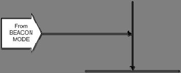

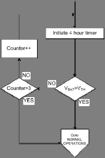
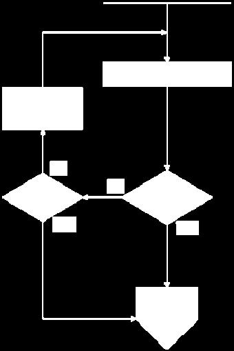
150 132
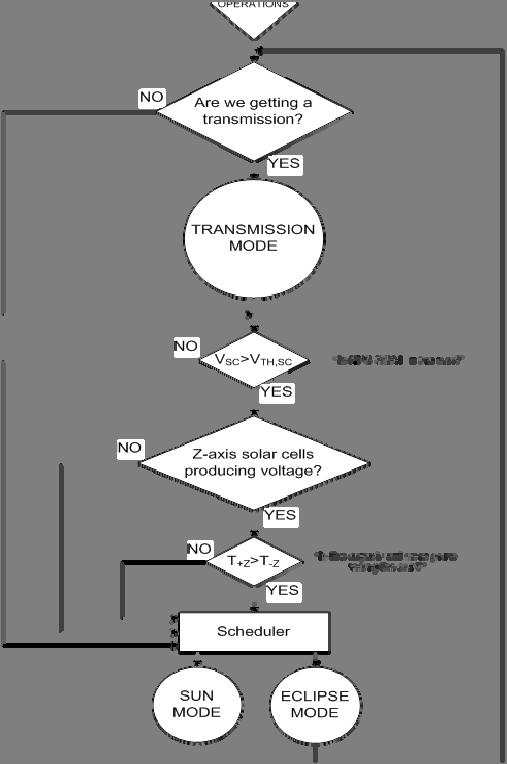
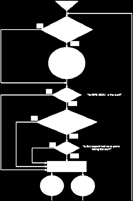
151 133
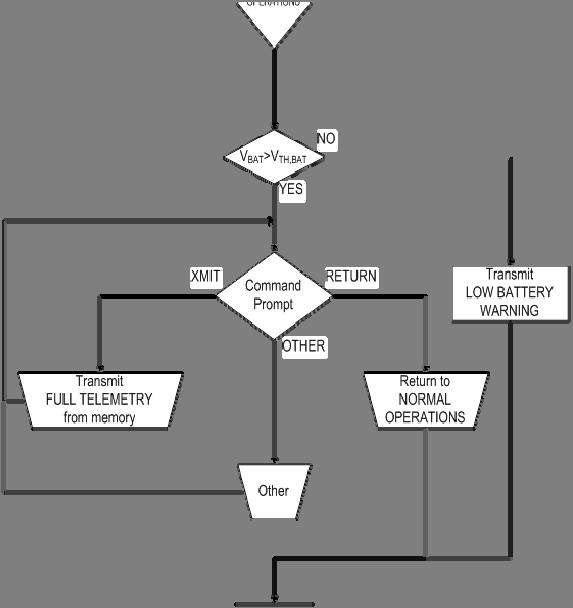
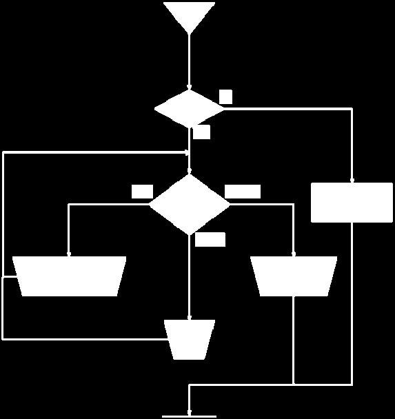
152 134
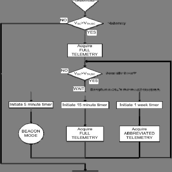
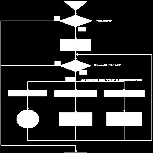
153 135
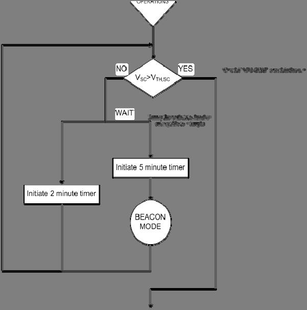
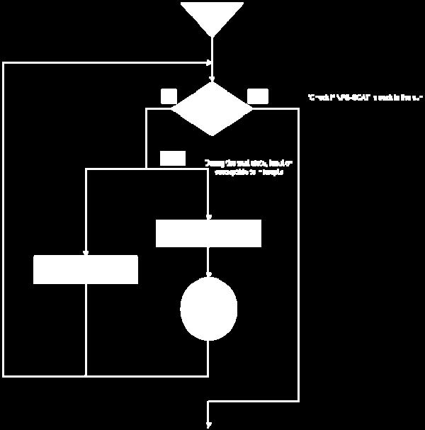
154 136
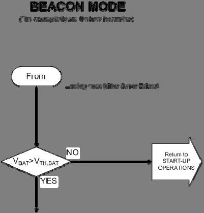
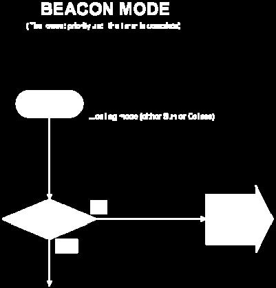


155 137
156 THIS PAGE INTENTIONALLY LEFT BLANK 138

157 APPENDIX C. MICROHARD MHX2420 SPECIFICATIONS 139
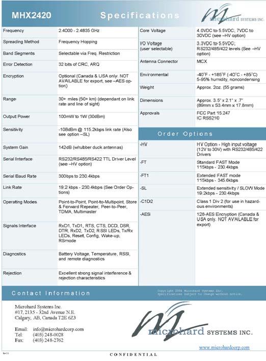
158 140

159 APPENDIX D LINK BUDGETS 141
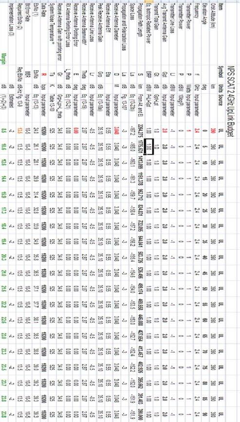
160 142
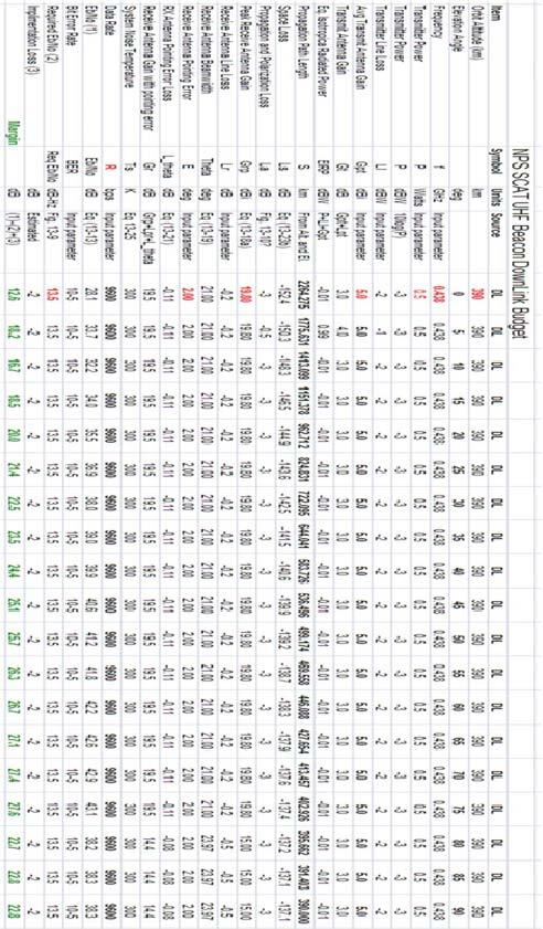
161 143
162 THIS PAGE INTENTIONALLY LEFT BLANK 144

163 APPENDIX E. SPECTRUM CONTROL INC., PATCH ANTENNA SPECIFICATIONS, DRAWINGS, AND MOUNTING PHOTO 145
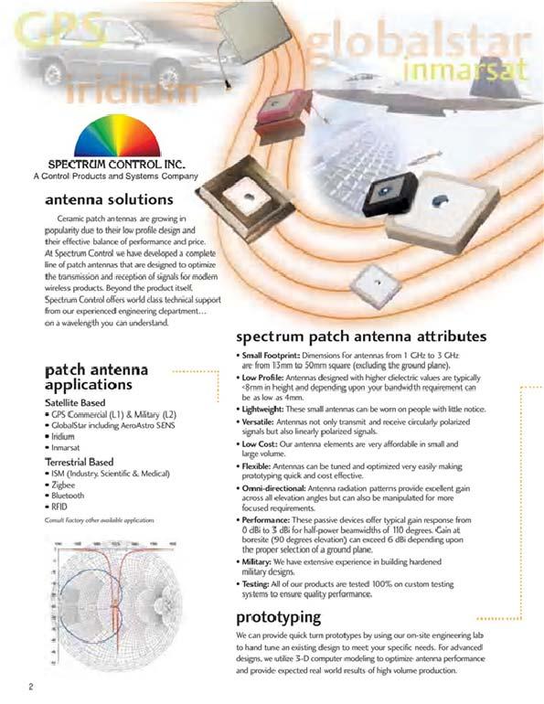
164 146
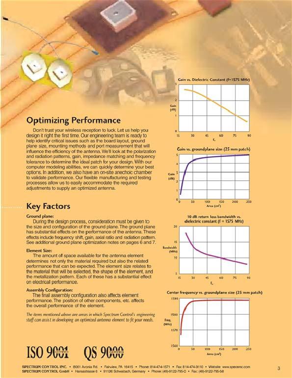
165 147
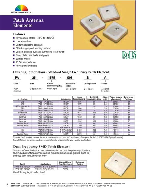
166 148
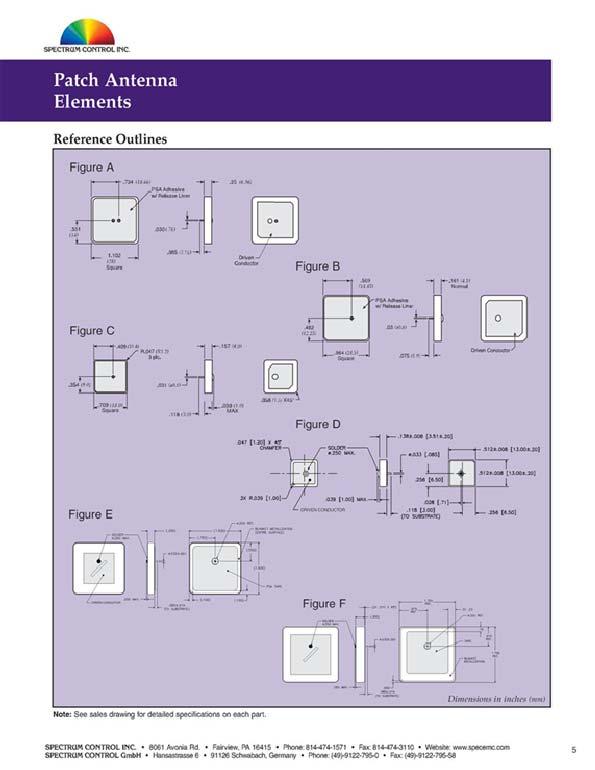
167 149
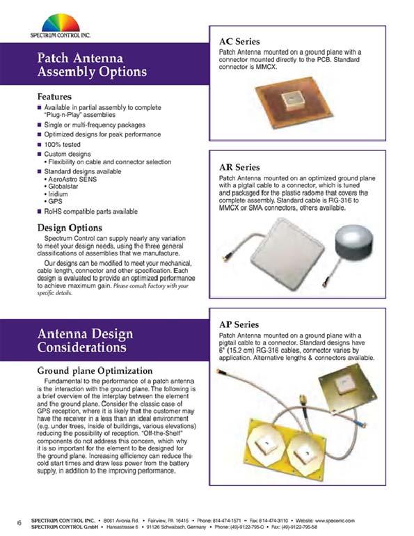
168 150
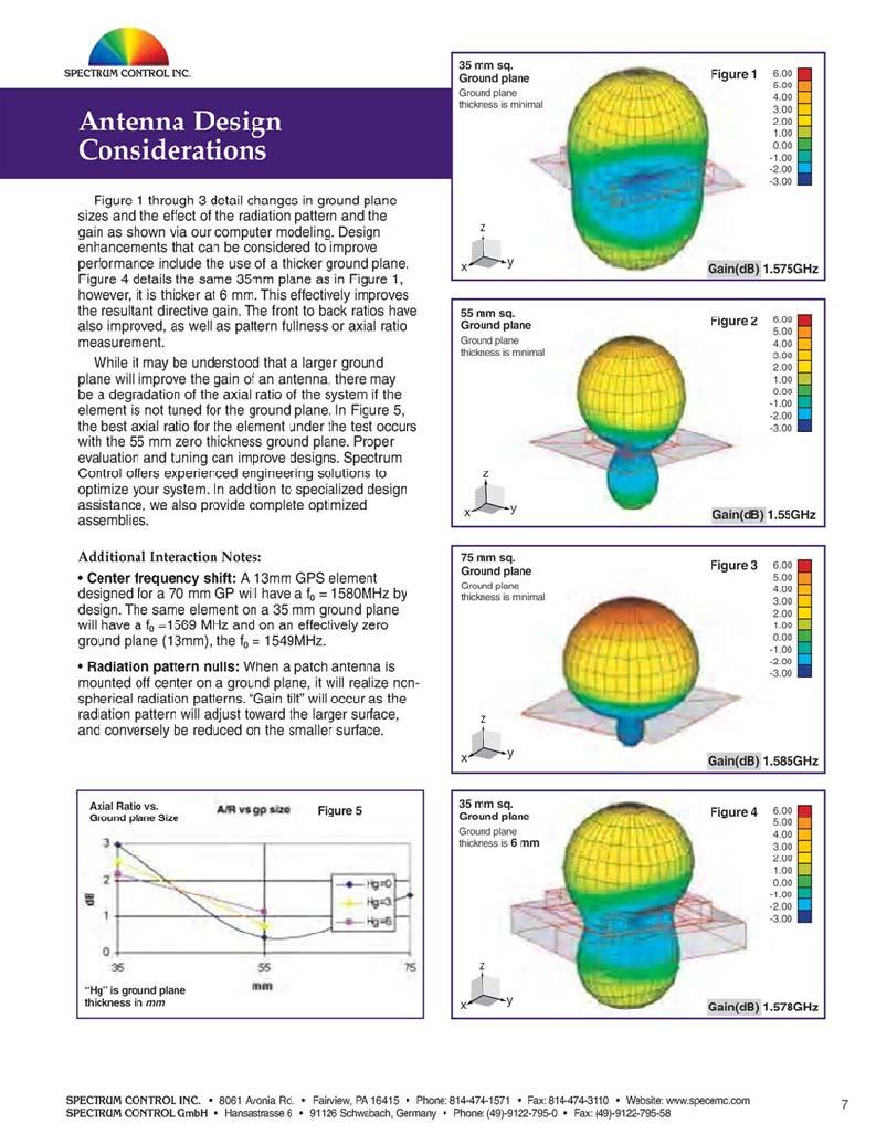
169 151
170 152
171 153
172 154
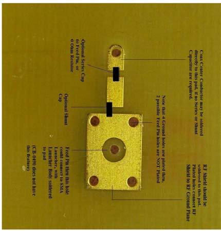
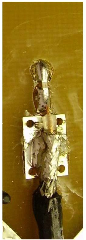
173 155
174 THIS PAGE INTENTIONALLY LEFT BLANK 156
175 APPENDIX F. NPS ANECHOIC CHAMBER SCHEMATIC 157
176 THIS PAGE INTENTIONALLY LEFT BLANK 158
177 APPENDIX G. TETHERS UNLIMITED INC., MICROHARD CONFIGURATION NOTES For MAST, we had what I referred to as two different types of radio parameter sets: stuff that never changed and was hard-coded in the software and stuff that was configurable post-launch. For the stuff that never changed, there was a hard coded sequence of commands sent in the following order (this was an array of strings in program memory): "E1", // Command Echos: 0=disable command echos, 1=enable command echos "Q0", // Quite Mode: 0=enable results, 1=disable results "V1", // Verbose Responses: 0=responses as numbers, 1=responses as words "W0", // Connection Result: 0=CONNECT xxxx, 1=CARRIER xxxx, 2=CONNECT xxxx "&C1", // DCD: 0=always on, 1=on when synchronized, 2=output data framing, 3=sync pulse "&D2", // DTR: 0=ignored, 2=force command mode, 3=resets modem "&K3", // Handshaking: 0=disabled, 2=RTS/CTS input framing, 3=enabled "&S1", // DSR: 0=always on, 1=on in data mode only, 2=DSR/DTR signaling "&E0", // Framing Errors: 0=disable checking, 1=enable checking "S0=0", // Auto Answer: 0=power up in command mode, 1=power up in data mode "S2=43", // Escape Code: 43='+' set to default and known value "S3=13", // Carriage Return: set to default and known value "S4=10", // Line Feed: set to default and known value "S5=8", // Backspace: set to default and known value "S101=3", // Operating Mode: 1=Master P-M, 2=Master P-P, 3=Slave, 4=Rpeater, 5=Master Diagnostics "S109=7", // Hopping Interval: unused in slaves but set to known value, 7=80msec "S110=1", // Date Format: 1=8N1, 2=8N2, 3=8E1, 4=8O1, 5=7N1, 6=7N2, 7=7E1, 8=7O1, 9=7E2, 10=7O2, 11=9N1 "S113=0", // Packet Retransmissions: unused in slaves, but set to known value "S117=0", // Modbus Mode: 0=disabled, 1=enabled "S119=1", // Quick Enter to Command: 0=disabled, 1=enabled "S120=0", // RTS/DCD Framing Interval: unused without input framing, but set to known value "S121=0", // DCD Timing: unused without input framing, but set to known value "S122=1", // Remote Control: 0=disabled, 1=enabled "S124=0", // TDMA Duty Cycle: unused in slaves, but set to known value "S125=0", // TDMA Max Address: unused in slaves, but set to known value "S126=0", // Data Protocol: 0=Transparent IN/OUT "S127=1", // Address Filtering: 0=disabled, 1=enabled "S128=1", // Multicast Association: 0=65535 only, 1=0 and "S129=0", // Secondary Master: unused in slaves, but set to known value "S206=0", // Secondary Hopping Pattern: unused in slaves, but set to known value 159
178 For the stuff that was configurable post-launch, these are the defaults that we used: - output power (we intelligently varied this between 250mW and 1W based on current battery charge level because we were having voltage regulator dropouts at the higher output powers when the battery was more discharged) - minimum packet size: 6 bytes (this was our minimum frame size for our messaging protocol) - maximum packet size: 100 bytes (I think I remember increasing this to 255 during operations to increase overall throughput) - packet size control (S114) (I don't remember what this means, but we defaulted to NOT overriding) - packet buffer timeout: 250ms - packet retry limit: 4 - packet repeat interval: 1 - network address: arbitrary - unit address: arbitrary - encryption key: arbitrary - slave roaming: enabled 1. Slave Roaming a. When enabled, a slave will scan other hopping patterns while attempting to synchronize with a master. In essence, it will tune to the hopping pattern of any communicating a master. b. Results i. When enabled, synchronization is possible regardless of the slave s hopping pattern. The synchronization process is noticeably (albeit not by much) faster when the hopping patterns are set to the same pattern. ii. When disabled, synchronization is only possible when the master s hopping pattern matches that of the slave. Synchronization appeared a little slower than when roaming was enabled and the hopping patterns matched. Also, the master was unable to synchronize with the slave even if its hopping pattern was within the same group. iii. The manual states that the master must be using a hopping pattern from the same group for the roaming slave to tune to the master. This statement seems to be false as the slave would synchronize with the master even if the slave s hopping pattern was in an entirely different group than the master s. c. Implications 160
179 i. Allowing the slave to roam in a noisy and low link margin environment with other transmitting masters, will likely increase the time in which it takes to synchronize to a slave. ii. If roaming is disabled, and a single event upset changes the hopping pattern of the slave and goes unnoticed by the flight software, then communication will be impossible. Each pattern would need to be scanned by the master in an attempt to find the slave. 2. Hop Interval a. Results i. Very short hop intervals made synchronization impossible. The hopping interval should be at least 20msec to allow synchronization to succeed. Synchronization was possible at every hopping interval greater than and equal to 20msec. 3. Address Filtering and Multicast Association a. With both of these enabled, a slave can receive data if its unit address does not match that of the master and if the unit address of the master is 0 or For the slave to transmit, its unit address must match that of the master. b. Implications i. Both of these should be enabled as it will allow the slave to receive packets (and thereby the flight software can receive commands) even if a single event upset alters the slave s unit address. 4. Point-to-Multipoint vs. Point-to-Point a. Synchronization appears to be much quicker when the master is configured as a point-to-multipoint than when it is configured as a point-to-point. 161
180 THIS PAGE INTENTIONALLY LEFT BLANK 162

181 APPENDIX H. DD1494 AND FCC FORM 422 APPLICATIONS FOR GENESAT, KENTUCKY SPACE CONSORTIUM, AND NPS- SCAT 163

182 164
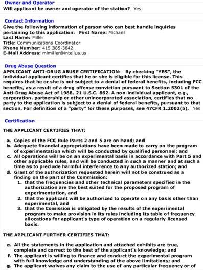
183 165
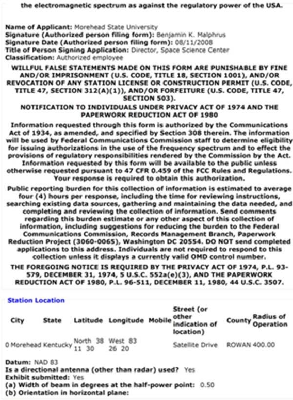
184 166
? If \"YES\", include as an exhibit the following information: a.")
185 QUESTION 6: PURPOSE OF EXPERIMENT 6. * Is this authorization to be used for providing communications essential to a research project? (The radio communication is not the objective of the research project)? If "YES", include as an exhibit the following information: a. A description of the nature of the research project being conducted. b. A showing that the communications facilities requested are necessary for the research project. c. A showing that existing communications facilities are inadequate. NOTE: When submitting this exhibit, please enter "QUESTION 6: PURPOSE OF EXPERIMENT" in the description field and select the type of document as "Text Documents".) ANTENNA DRAWING: Submit as an exhibit a vertical profile sketch of total structure including supporting building, if any, giving heights in meters above ground for all significant features. Clearly indicate existing portion, noting particulars of aviation obstruction lightly already available. Submit this sketch under the "Antenna Drawing" exhibit type. NECESSARY BANDWIDTH DESCRIPTION Please indicate the necessary bandwidth measurement and indicate the units by selecting one of the values in the 167
186 drop-down list. Submit an exhibit describing how the necessary bandwidth was calculated for all the indicated frequencies. Exhibits may be entered immediately after submitting this form or later by selecting the "Add Attachments" option from this web site's menu. NOTE: When submitting this exhibit, please enter "NECESSARY BANDWIDTH DESCRIPTION". in the exhibit description. MODULATING SIGNAL DESCRIPTION (entered BPSK ) Insert as appropriate for the type of modulation (e.g. The maximum speed for keying in bauds, maximum audio modulating frequency, frequency deviation of carrier, pulse duration and repetition rate). For complex emissions, submit an exhibit describing in detail the modulating signal and indicate the frequency range that it is associated with. Exhibits may be entered immediately after submitting this form or later by selecting the "Add Attachments" option from this web site's menu. NOTE: When submitting this exhibit, please enter "MODULATING SIGNAL DESCRIPTION". in the exhibit description. Morehead State University 21 M Space Tracking Antenna ANTENNA DRAWING: Vertical profile sketch of total structure of the Morehead State University 21 M Space Tracking Antenna including supporting building, with heights in meters above ground for all significant features. 168
187 Dimensions Reflector: 21 m (68.9 ft) Maximum vertical height above ground (apex of feed at 90 degrees elevation): 25.6 m (84 ft) Height to elevation axle: m (46.5 ft.) Height to center of feed ring at 0 degrees pointing elevation: m (46.5 ft.) Height of LER 3.08 m (10.1 ft) 169

188 Photograph of the Morehead State University Space Science Center 21 Meter Space Tracking Antenna September,
189 171
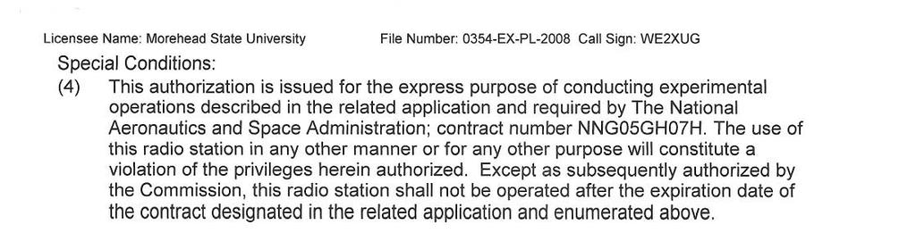
190 172
NPS-SCAT communications system : design, test, and integration of NPS' first CUBESAT
 Calhoun: The NPS Institutional Archive DSpace Repository Theses and Dissertations Thesis and Dissertation Collection 2010-09 NPS-SCAT communications system : design, test, and integration of NPS' first
Naval Postgraduate School
 Naval Postgraduate School NPS-Solar Cell Array Tester 2009 CubeSat Developers Workshop LCDR Chris Malone, USN MAJ Christopher Ortiona, USA LCDR William Crane USN, LCDR Lawrence Dorn USN, LT Robert Jenkins
Amateur Radio and the CubeSat Community
 Amateur Radio and the CubeSat Community Bryan Klofas KF6ZEO bklofas@calpoly.edu Electrical Engineering Department California Polytechnic State University, San Luis Obispo, CA Abstract This paper will explore
RAX: The Radio Aurora explorer
 RAX: Matt Bennett University of Michigan CubeSat Workshop Cal Poly, San Luis Obispo April 22 nd, 2009 Background Sponsored by National Science Foundation University of Michigan and SRI International Collaboration
Presentation to TEXAS II
 Presentation to TEXAS II Technical exchange on AIS via Satellite II Dr. Dino Lorenzini Mr. Mark Kanawati September 3, 2008 3554 Chain Bridge Road Suite 103 Fairfax, Virginia 22030 703-273-7010 1 Report
2013 RockSat-C Preliminary Design Review
 2013 RockSat-C Preliminary Design Review TEC (The Electronics Club) Eastern Shore Community College Melfa, VA Larry Brantley, Andrew Carlton, Chase Riley, Nygel Meece, Robert Williams Date 10/26/2012 Mission
Satellite Engineering BEST Course. CubeSats at ULg
 Satellite Engineering BEST Course CubeSats at ULg Nanosatellite Projects at ULg Primary goal Hands-on satellite experience for students 2 Nanosatellite Projects at ULg Primary goal Hands-on satellite experience
NAVAL POSTGRADUATE SCHOOL THESIS
 NAVAL POSTGRADUATE SCHOOL MONTEREY, CALIFORNIA THESIS ELECTRICAL POWER SUBSYTEM INTEGRATION AND TEST FOR THE NPS SOLAR CELL ARRAY TESTER CUBESAT by James Martin Fletcher December 2010 Thesis Advisor: Second
Tropnet: The First Large Small-Satellite Mission
 Tropnet: The First Large Small-Satellite Mission SSC01-II4 J. Smith One Stop Satellite Solutions 1805 University Circle Ogden Utah, 84408-1805 (801) 626-7272 jay.smith@osss.com Abstract. Every small-satellite
MISSION OPERATION FOR THE KUMU A`O CUBESAT. Zachary K. Lee-Ho Department of Mechanical Engineering University of Hawai i at Mānoa Honolulu, HI 96822
 MISSION OPERATION FOR THE KUMU A`O CUBESAT Zachary K. Lee-Ho Department of Mechanical Engineering University of Hawai i at Mānoa Honolulu, HI 96822 ABSTRACT UH is currently developing its 5 th generation
University. Federal University of Santa Catarina (UFSC) Florianópolis/SC - Brazil. Brazil. Embedded Systems Group (UFSC)
 Florianópolis/SC - Brazil. Brazil. Embedded Systems Group (UFSC)") University 1 Federal University of Santa Catarina (UFSC) Florianópolis/SC - Brazil Brazil Agenda 2 Partnership Introduction Subsystems Payload Communication System Power System On-Board Computer Attitude
University 1 Federal University of Santa Catarina (UFSC) Florianópolis/SC - Brazil Brazil Agenda 2 Partnership Introduction Subsystems Payload Communication System Power System On-Board Computer Attitude
CubeSat Integration into the Space Situational Awareness Architecture
 CubeSat Integration into the Space Situational Awareness Architecture Keith Morris, Chris Rice, Mark Wolfson Lockheed Martin Space Systems Company 12257 S. Wadsworth Blvd. Mailstop S6040 Littleton, CO
In the summer of 2002, Sub-Orbital Technologies developed a low-altitude
 1.0 Introduction In the summer of 2002, Sub-Orbital Technologies developed a low-altitude CanSat satellite at The University of Texas at Austin. At the end of the project, team members came to the conclusion
I Need Your Cost Estimate for a 10 Year Project by Next Week
 I Need Your Cost Estimate for a 10 Year Project by Next Week A Case Study in Broad System Analysis: DoD Spectrum Reallocation Feasibility Study, 1755-1850 MHz Momentum From Industry & Response from Government
Poly Picosatellite Orbital Deployer Mk. III Rev. E User Guide
 The CubeSat Program California Polytechnic State University San Luis Obispo, CA 93407 X Document Classification Public Domain ITAR Controlled Internal Only Poly Picosatellite Orbital Deployer Mk. III Rev.
CanX-2 and NTS Canada's Smallest Operational Satellites
 CanX-2 and NTS Canada's Smallest Operational Satellites Daniel D. Kekez Space Flight Laboratory University of Toronto Institute for Aerospace Studies 9 August 2008 Overview Introduction to UTIAS/ SFL Mission
From Single to Formation Flying CubeSats: An Update of the Delfi Programme
 From Single to Formation Flying CubeSats: An Update of the Delfi Programme Jian Guo, Jasper Bouwmeester & Eberhard Gill 1 Outline Introduction Delfi-C 3 Mission Delfi-n3Xt Mission Lessons Learned DelFFi
The Nemo Bus: A Third Generation Nanosatellite Bus for Earth Monitoring and Observation
 The Nemo Bus: A Third Generation Nanosatellite Bus for Earth Monitoring and Observation FREDDY M. PRANAJAYA Manager, Advanced Systems Group S P A C E F L I G H T L A B O R A T O R Y University of Toronto
Why, What, Who, When & Where of Nanosatellites. Alfred Ng Canadian Space Agency
 Why, What, Who, When & Where of Nanosatellites Alfred Ng Canadian Space Agency Outline What is a nanosat Why nanosatellite? When did it start? What are the nanosat missions? Who is funding it? Who is doing
The Future of CubeSat Data Communications
 The Future of CubeSat Data Communications Bryan Klofas KF6ZEO SRI International bryan.klofas@sri.com AMSAT-NA Symposium Orlando, Florida 26 October 2012 CubeSat Launches (1 of 3) Eurockot Launch (30 June
Petite Amateur Navy Satellite
 Petite Amateur Navy Satellite Steven R. Bible, N7HPR Dan Sakoda, KD6DRA n7hpr@amsat.org dsakoda@nps.navy.mil Space Systems Academic Group Naval Postgraduate School Monterey, CA 93943 Introduction The Naval
Solar Radar Experiments
 Solar Radar Experiments Paul Rodriguez Plasma Physics Division Naval Research Laboratory Washington, DC 20375 phone: (202) 767-3329 fax: (202) 767-3553 e-mail: paul.rodriguez@nrl.navy.mil Award # N0001498WX30228
ISIS Innovative Solutions In Space B.V.
 ISIS Innovative Solutions In Space B.V. Setting the scene: enabling small satellites to utilize their full potential (or: does satellite size matter?) Wouter Jan Ubbels ITU Symposium and Workshop on small
CubeSat Design Specification
 Document Classification X Public Domain ITAR Controlled Internal Only CubeSat Design Specification (CDS) Revision Date Author Change Log 8 N/A Simon Lee N/A 8.1 5/26/05 Amy Hutputanasin Formatting updated.
REPORT DOCUMENTATION PAGE
 REPORT DOCUMENTATION PAGE Form Approved OMB NO. 0704-0188 The public reporting burden for this collection of information is estimated to average 1 hour per response, including the time for reviewing instructions,
(U) A Path Forward for Small Satellite Ground Architecture
 A Path Forward for Small Satellite Ground Architecture") (U) A Path Forward for Small Satellite Ground Architecture LtCol Joseph Gueck: gueckjos@nro.mil MAJ Benjamin Seth Bowden: bowdenbe@msd.nro.mil Mr. David C. Williamson: willdavi@msd.nro.mil 2013 Ground
(U) A Path Forward for Small Satellite Ground Architecture LtCol Joseph Gueck: gueckjos@nro.mil MAJ Benjamin Seth Bowden: bowdenbe@msd.nro.mil Mr. David C. Williamson: willdavi@msd.nro.mil 2013 Ground
Single event upsets and noise margin enhancement of gallium arsenide Pseudo-Complimentary MESFET Logic
 Calhoun: The NPS Institutional Archive Theses and Dissertations Thesis Collection 1995-06 Single event upsets and noise margin enhancement of gallium arsenide Pseudo-Complimentary MESFET Logic Van Dyk,
Delfi-C. Update and Flight Results Wouter Weggelaar PA3WEG. 26 July 2009
 Delfi-C 3 Update and Flight Results Wouter Weggelaar PA3WEG 1 Delfi-C3 quick facts 3U CubeSat NO Battery NO active attitude control 1200Bd BPSK downlink Linear transponder Payloads: Thin Film Solar Cells
Sky Satellites: The Marine Corps Solution to its Over-The-Horizon Communication Problem
 Sky Satellites: The Marine Corps Solution to its Over-The-Horizon Communication Problem Subject Area Electronic Warfare EWS 2006 Sky Satellites: The Marine Corps Solution to its Over-The- Horizon Communication
10 August 2005 Utah State University Logan, UT
 19th Annual AIAA SmallSat Conference The *.Sat CubeSat Bus When Three Cubes Meet Eric P. Lee, *.Sat Project Manager (eric.p.lee@lmco.com, leeep@stanford.edu) and Matthew D Ortenzio, Stevan M. Spremo, Belgacem
US Army Research Laboratory and University of Notre Dame Distributed Sensing: Hardware Overview
 ARL-TR-8199 NOV 2017 US Army Research Laboratory US Army Research Laboratory and University of Notre Dame Distributed Sensing: Hardware Overview by Roger P Cutitta, Charles R Dietlein, Arthur Harrison,
NAVAL POSTGRADUATE SCHOOL
 NPS-SP-08-001 NAVAL POSTGRADUATE SCHOOL MONTEREY, CALIFORNIA STRUCTURAL DESIGN OF A NPS CUBESAT LAUNCHER by Felix Roßberg January 2008 Approved for public release; distribution is unlimited Prepared for:
The Future for CubeSats Present and Coming Launch Opportunities 18th Annual AIAA / USU Conference on Small Satellites CubeSat Workshop
 The Future for CubeSats Present and Coming Launch Opportunities 18th Annual AIAA / USU Conference on Small Satellites CubeSat Workshop Presented By: Armen Toorian California Polytechnic State University
A RENEWED SPIRIT OF DISCOVERY
 A RENEWED SPIRIT OF DISCOVERY The President s Vision for U.S. Space Exploration PRESIDENT GEORGE W. BUSH JANUARY 2004 Report Documentation Page Form Approved OMB No. 0704-0188 Public reporting burden for
NAVAL POSTGRADUATE SCHOOL Monterey, California SHALLOW WATER HYDROTHERMAL VENT SURVEY IN AZORES WITH COOPERATING ASV AND AUV
 NPS-ME-02-XXX NAVAL POSTGRADUATE SCHOOL Monterey, California SHALLOW WATER HYDROTHERMAL VENT SURVEY IN AZORES WITH COOPERATING ASV AND AUV by A. J. Healey, A. M. Pascoal, R. Santos January 2002 PROJECT
The CubeSTAR Project. Design of a Prototype Communication System for the CubeSTAR Nano-satellite. Master presentation by Johan Tresvig 24th Aug.
 Design of a Prototype Communication System for the CubeSTAR Nano-satellite Master presentation by Johan Tresvig 24th Aug. 2010 The CubeSTAR Project Student satellite project at the University of Oslo Scientific
A Multi-Use Low-Cost, Integrated, Conductivity/Temperature Sensor
 A Multi-Use Low-Cost, Integrated, Conductivity/Temperature Sensor Guy J. Farruggia Areté Associates 1725 Jefferson Davis Hwy Suite 703 Arlington, VA 22202 phone: (703) 413-0290 fax: (703) 413-0295 email:
NAVAL POSTGRADUATE SCHOOL THESIS
 NAVAL POSTGRADUATE SCHOOL MONTEREY, CALIFORNIA THESIS NPS CUBESAT LAUNCHER DESIGN, PROCESS AND REQUIREMENTS by Matthew Richard Crook June 2009 Thesis Advisor: Second Reader: James H. Newman Daniel J. Sakoda
Coach Class to Orbit: the NPS CubeSat Launcher
 Calhoun: The NPS Institutional Archive Faculty and Researcher Publications Faculty and Researcher Publications Collection 2009-08 Coach Class to Orbit: the NPS CubeSat Launcher Hicks, Christina http://hdl.handle.net/10945/37306
Automatic Payload Deployment System (APDS)
") Automatic Payload Deployment System (APDS) Brian Suh Director, T2 Office WBT Innovation Marketplace 2012 Report Documentation Page Form Approved OMB No. 0704-0188 Public reporting burden for the collection
Automatic Payload Deployment System (APDS) Brian Suh Director, T2 Office WBT Innovation Marketplace 2012 Report Documentation Page Form Approved OMB No. 0704-0188 Public reporting burden for the collection
Outernet: Development of a 1U Platform to Enable Low Cost Global Data Provision
 Outernet: Development of a 1U Platform to Enable Low Cost Global Data Provision Introduction One of the UK s leading space companies, and the only wholly UK-owned Prime contractor. ISO 9001:2008 accredited
UKube-1 Platform Design. Craig Clark
 UKube-1 Platform Design Craig Clark Ukube-1 Background Ukube-1 is the first mission of the newly formed UK Space Agency The UK Space Agency gave us 5 core mission objectives: 1. Demonstrate new UK space
UCISAT-1. Current Completed Model. Former Manufactured Prototype
 UCISAT-1 2 Current Completed Model Former Manufactured Prototype Main Mission Objectives 3 Primary Mission Objective Capture an image of Earth from LEO and transmit it to the K6UCI Ground Station on the
THE RESEARCH AND DEVELOPMENT OF THE USM NANOSATELLITE FOR REMOTE SENSING MISSION
 THE RESEARCH AND DEVELOPMENT OF THE USM NANOSATELLITE FOR REMOTE SENSING MISSION Md. Azlin Md. Said 1, Mohd Faizal Allaudin 2, Muhammad Shamsul Kamal Adnan 2, Mohd Helmi Othman 3, Nurulhusna Mohamad Kassim
PicoSat Mission Examples and Design Suggestions. Department of Electrical Engineering National Cheng Kung University
 PICOSAT SYSTEM ENGINEERIN PicoSat Mission Examples and Design Suggestions Department of Electrical Engineering National Cheng Kung University juang@mail.ncku.edu.tw 2 Contents Introduction Motivations
KySat-2: Status Report and Overview of C&DH and Communications Systems Design
 KySat-2: Status Report and Overview of C&DH and Communications Systems Design Jason Rexroat University of Kentucky Kevin Brown Morehead State University Twyman Clements Kentucky Space LLC 1 Overview Mission
Michigan Multipurpose MiniSat M-Cubed. Kiril Dontchev Summer CubeSat Workshop: 8/9/09
 Michigan Multipurpose MiniSat M-Cubed Kiril Dontchev Summer CubeSat Workshop: 8/9/09 Michigan NanoSat Pipeline Inputs Outputs U of M Ideas Innovative technology Entrepreneurial thought Science Papers Flight
CubeSat Communication System, a New Design Approach
 CubeSat Communication System, a New Design Approach Ayman N. Mohi, Jabir S. Aziz, Lubab A. Salman # Department of Electronic and Communications Engineering, College of Engineering, Al-Nahrain University
The AFIT of Today is the Air Force of Tomorrow.
 Air Force Institute of Technology Rapid Build and Space Qualification of CubeSats Joshua Debes Nathan Howard Ryan Harrington Richard Cobb Jonathan Black SmallSat 2011 Air Force Institute of Technology
The Future of CubeSat Communications: Transitioning Away from Amateur Radio Frequencies for High-speed Downlinks
 The Future of CubeSat Communications: Transitioning Away from Amateur Radio Frequencies for High-speed Downlinks Bryan Klofas (KF6ZEO), Kyle Leveque (KG6TXT) SRI International bryan.klofas@sri.com, kyle.leveque@sri.com
NanoSatellite Activity at the UTIAS Space Flight Laboratory
 NanoSatellite Activity at the UTIAS Space Flight Laboratory Robert E. Zee, Ph.D. Managing Director, Space Flight Laboratory University of Toronto Institute for Aerospace Studies 4925 Dufferin Street, Toronto,
Self-Steering Antennas for CubeSat Networks
 Self-Steering Antennas for CubeSat Networks Blaine Murakami and Wayne Shiroma University of Hawaii CubeSat Developers Workshop CalPoly - San Luis Obispo March 9, 2004 Outline Overview of the UH Small-Satellite
ULTRASTABLE OSCILLATORS FOR SPACE APPLICATIONS
 ULTRASTABLE OSCILLATORS FOR SPACE APPLICATIONS Peter Cash, Don Emmons, and Johan Welgemoed Symmetricom, Inc. Abstract The requirements for high-stability ovenized quartz oscillators have been increasing
NCUBE: The first Norwegian Student Satellite. Presenters on the AAIA/USU SmallSat: Åge-Raymond Riise Eystein Sæther
 NCUBE: The first Norwegian Student Satellite Presenters on the AAIA/USU SmallSat: Åge-Raymond Riise Eystein Sæther Motivation Build space related competence within: mechanical engineering, electronics,
ARMADILLO: Subsystem Booklet
 ARMADILLO: Subsystem Booklet Mission Overview The ARMADILLO mission is the Air Force Research Laboratory s University Nanosatellite Program s 7 th winner. ARMADILLO is a 3U cube satellite (cubesat) constructed
From the Delfi-C3 nano-satellite towards the Delfi-n3Xt nano-satellite
 From the Delfi-C3 nano-satellite towards the Delfi-n3Xt nano-satellite Geert F. Brouwer, Jasper Bouwmeester Delft University of Technology, The Netherlands Faculty of Aerospace Engineering Chair of Space
NAVY SATELLITE COMMUNICATIONS
 NAVY SATELLITE COMMUNICATIONS Item Type text; Proceedings Authors Captain Newell, John W. Publisher International Foundation for Telemetering Journal International Telemetering Conference Proceedings Rights
Loop-Dipole Antenna Modeling using the FEKO code
 Loop-Dipole Antenna Modeling using the FEKO code Wendy L. Lippincott* Thomas Pickard Randy Nichols lippincott@nrl.navy.mil, Naval Research Lab., Code 8122, Wash., DC 237 ABSTRACT A study was done to optimize
ABSTRACT INTRODUCTION
 COMPASS-1 PICOSATELLITE: STRUCTURES & MECHANISMS Marco Hammer, Robert Klotz, Ali Aydinlioglu Astronautical Department University of Applied Sciences Aachen Hohenstaufenallee 6, 52064 Aachen, Germany Phone:
1. Detect and locate potentially illegal fishing ship using satellite image, AIS data, and external sources.
 Title: Development of Microsatellite to Detect Illegal Fishing MS-SAT Primary Point of Contact (POC) & email: Dr. Ridanto Eko Poetro; ridanto@ae.itb.ac.id Co-authors: Ernest Sebastian C., Bintang A.S.W.A.M.
Cross-layer Approach to Low Energy Wireless Ad Hoc Networks
 Cross-layer Approach to Low Energy Wireless Ad Hoc Networks By Geethapriya Thamilarasu Dept. of Computer Science & Engineering, University at Buffalo, Buffalo NY Dr. Sumita Mishra CompSys Technologies,
Effects of Fiberglass Poles on Radiation Patterns of Log-Periodic Antennas
 Effects of Fiberglass Poles on Radiation Patterns of Log-Periodic Antennas by Christos E. Maragoudakis ARL-TN-0357 July 2009 Approved for public release; distribution is unlimited. NOTICES Disclaimers
USNA-0601 ParkinsonSAT Remote Data Relay (Psat) Cubesat Conference Aug 2012
 Cubesat Conference Aug 2012") USNA-0601 ParkinsonSAT Remote Data Relay (Psat) Cubesat Conference Aug 2012 Psat BRICsat Ocean Buoys w/ RF Terminals GROUND STATION Data Exfiltration Bob Bruninga Midns: Buck, Kimball, Lung, Mahelik, Rehume,
USNA-0601 ParkinsonSAT Remote Data Relay (Psat) Cubesat Conference Aug 2012 Psat BRICsat Ocean Buoys w/ RF Terminals GROUND STATION Data Exfiltration Bob Bruninga Midns: Buck, Kimball, Lung, Mahelik, Rehume,
Janice C. Booth Weapons Development and Integration Directorate Aviation and Missile Research, Development, and Engineering Center
 TECHNICAL REPORT RDMR-WD-17-30 THREE-DIMENSIONAL (3-D) PRINTED SIERPINSKI PATCH ANTENNA Janice C. Booth Weapons Development and Integration Directorate Aviation and Missile Research, Development, and Engineering
Frequency bands and transmission directions for data relay satellite networks/systems
 Recommendation ITU-R SA.1019-1 (07/2017) Frequency bands and transmission directions for data relay satellite networks/systems SA Series Space applications and meteorology ii Rec. ITU-R SA.1019-1 Foreword
PolySat Launch and Operations
 PolySat Launch and Operations Cubesat Developers Summer Workshop Logan, Utah 12 August 2007 PolySat Objective: Engineering Education Objective: Provide a reliable bus system to allow for flight qualification
Satellite Sub-systems
 Satellite Sub-systems Although the main purpose of communication satellites is to provide communication services, meaning that the communication sub-system is the most important sub-system of a communication
The M-Cubed/COVE Mission
 The M-Cubed/COVE Mission Matt Bennett 1, Andrew Bertino 2, James Cutler 2, Charles Norton 1, Paula Pingree 1, John Springmann 2, Scott Tripp 2 CubeSat Developers Workshop April 18, 2012 1 Jet Propulsion
Modeling Antennas on Automobiles in the VHF and UHF Frequency Bands, Comparisons of Predictions and Measurements
 Modeling Antennas on Automobiles in the VHF and UHF Frequency Bands, Comparisons of Predictions and Measurements Nicholas DeMinco Institute for Telecommunication Sciences U.S. Department of Commerce Boulder,
CUBESATS: A COST-EFFICIENT WAY TO VALIDATE TECHNOLOGICAL BRICKS
 CUBESATS: A COST-EFFICIENT WAY TO VALIDATE TECHNOLOGICAL BRICKS E. Rakotonimbahy 1, K. Dohlen 1, P. Balard 1, R. El Ajjouri 1, S. Vives 1, A. Caillat 1, N. Baccichet 3 L. Iafolla 2, V. Iafolla 2, G. Savini
Multi-Element GPS Antenna Array on an. RF Bandgap Ground Plane. Final Technical Report. Principal Investigator: Eli Yablonovitch
 Multi-Element GPS Antenna Array on an RF Bandgap Ground Plane Final Technical Report Principal Investigator: Eli Yablonovitch University of California, Los Angeles Period Covered: 11/01/98-11/01/99 Program
Willie D. Caraway III Randy R. McElroy
 TECHNICAL REPORT RD-MG-01-37 AN ANALYSIS OF MULTI-ROLE SURVIVABLE RADAR TRACKING PERFORMANCE USING THE KTP-2 GROUP S REAL TRACK METRICS Willie D. Caraway III Randy R. McElroy Missile Guidance Directorate
GLOBAL POSITIONING SYSTEM SHIPBORNE REFERENCE SYSTEM
 GLOBAL POSITIONING SYSTEM SHIPBORNE REFERENCE SYSTEM James R. Clynch Department of Oceanography Naval Postgraduate School Monterey, CA 93943 phone: (408) 656-3268, voice-mail: (408) 656-2712, e-mail: clynch@nps.navy.mil
Aug 6 th, Presented by: Danielle George- Project Manager Erin McCaskey Systems Engineer. LSP-F , Rev. B
 Aug 6 th, 2011 Presented by: Danielle George- Project Manager Erin McCaskey Systems Engineer Agenda Purpose Background Firsts Activities Mission Objectives Con Ops Mission Timeline Risks Challenges Power
Best Practices for Technology Transition. Technology Maturity Conference September 12, 2007
 Best Practices for Technology Transition Technology Maturity Conference September 12, 2007 1 Report Documentation Page Form Approved OMB No. 0704-0188 Public reporting burden for the collection of information
Nanosat Deorbit and Recovery System to Enable New Missions
 SSC11-X-3 Nanosat Deorbit and Recovery System to Enable New Missions Jason Andrews, Krissa Watry, Kevin Brown Andrews Space, Inc. 3415 S. 116th Street, Ste 123, Tukwila, WA 98168, (206) 342-9934 jandrews@andrews-space.com,
On Discriminating CubeSats Launched Together
 On Discriminating CubeSats Launched Together Michael Cousins SRI International 2008 CubeSat Developer s Workshop San Luis Obispo, California 1 CubeSat Discrimination Scope: Discuss and explore the problem
RAX Communication Reflections
 RAX Communication Reflections James Cutler, Sara Spangelo, Matt Bennett, Andy Klesh, Hasan Bahcivan University of Michigan and SRI RAX EDU Ready for Shake Test Example Integration Testing RAX Communication
Brazilian Inter-University CubeSat Mission Overview
 Brazilian Inter-University CubeSat Mission Overview Victor Menegon, Leonardo Kessler Slongo, Lui Pillmann, Julian Lopez, William Jamir, Thiago Pereira, Eduardo Bezerra and Djones Lettnin. victormenegon.eel@gmail.com
Emergency Locator Signal Detection and Geolocation Small Satellite Constellation Feasibility Study
 Emergency Locator Signal Detection and Geolocation Small Satellite Constellation Feasibility Study Authors: Adam Gunderson, Celena Byers, David Klumpar Background Aircraft Emergency Locator Transmitters
Final Report for AOARD Grant FA Indoor Localization and Positioning through Signal of Opportunities. Date: 14 th June 2013
 Final Report for AOARD Grant FA2386-11-1-4117 Indoor Localization and Positioning through Signal of Opportunities Date: 14 th June 2013 Name of Principal Investigators (PI and Co-PIs): Dr Law Choi Look
The Algorithm Theoretical Basis Document for the Atmospheric Delay Correction to GLAS Laser Altimeter Ranges
 NASA/TM 2012-208641 / Vol 8 ICESat (GLAS) Science Processing Software Document Series The Algorithm Theoretical Basis Document for the Atmospheric Delay Correction to GLAS Laser Altimeter Ranges Thomas
Ground Systems for Small Sats: Simple, Fast, Inexpensive
 Ground Systems for Small Sats: Simple, Fast, Inexpensive but Effective 15 th Ground Systems Architecture Workshop March 1, 2011 Mr Andrew Kwas, Mr Greg Shreve, Northrop Grumman Corp, Mr Adam Yozwiak, Cornell
CubeSats: From Launch to Deployment Necessity for a standard.
 1 Necessity for a standard. Creation of a standard to facilitate the design process of small satellites. Deployment system to support the standard. Safe and reliable. Efficient and cost effective. Versatile.
REPORT DOCUMENTATION PAGE. A peer-to-peer non-line-of-sight localization system scheme in GPS-denied scenarios. Dr.
 REPORT DOCUMENTATION PAGE Form Approved OMB No. 0704-0188 The public reporting burden for this collection of information is estimated to average 1 hour per response, including the time for reviewing instructions,
RF Performance Predictions for Real Time Shipboard Applications
 DISTRIBUTION STATEMENT A. Approved for public release; distribution is unlimited. RF Performance Predictions for Real Time Shipboard Applications Dr. Richard Sprague SPAWARSYSCEN PACIFIC 5548 Atmospheric
National Aeronautics and Space Administration Jet Propulsion Laboratory California Institute of Technology
 QuikSCAT Mission Status QuikSCAT Follow-on Mission 2 QuikSCAT instrument and spacecraft are healthy, but aging June 19, 2009 will be the 10 year launch anniversary We ve had two significant anomalies during
Amateur Satellite and APRS Data Links. Polar Technology Conference April Bob Bruninga Midns: Kren, Aspholm
 Amateur Satellite and APRS Data Links Polar Technology Conference April 2012 Psat ODTML Ocean Buoys w/ RF Terminals GROUND STATION Bob Bruninga Midns: Kren, Aspholm US Naval Academy Satellite Lab 410-293-6417
ncube Spacecraft Specification Document
 ncube Spacecraft Specification Document 1. INTRODUCTION The Norwegian student satellite, ncube, is an experimental spacecraft that was developed and built by students from four Norwegian universities in
SYSTEMS INTEGRATION AND STABILIZATION OF A CUBESAT
 SYSTEMS INTEGRATION AND STABILIZATION OF A CUBESAT Tyson Kikugawa Department of Electrical Engineering University of Hawai i at Manoa Honolulu, HI 96822 ABSTRACT A CubeSat is a fully functioning satellite,
Development Opportunities within the CubeSat Kit Architecture
 Development Opportunities within the CubeSat Kit Architecture Andrew E. Kalman, Ph.D. Slide 1 Outline Part I: Historical Overview & Observations Part II: Internal Module Stacking Part III: Underutilized
Workshop on Intelligent System and Applications (ISA 17)
") Telemetry Mining for Space System Sara Abdelghafar Ahmed PhD student, Al-Azhar University Member of SRGE Workshop on Intelligent System and Applications (ISA 17) 13 May 2017 Workshop on Intelligent System
Telemetry Mining for Space System Sara Abdelghafar Ahmed PhD student, Al-Azhar University Member of SRGE Workshop on Intelligent System and Applications (ISA 17) 13 May 2017 Workshop on Intelligent System
GeneSat-1 Quick Look Mission Report
 GeneSat-1 Bruce Yost Mission Manager (650)691-0676 GeneSat-1 Project Team GeneSat-1Project M J. Hines Payload Segment C. Friedericks Space Segment C. Freidericks MIssion Managemen
ELaNa Educational Launch of Nanosatellite Providing Routine RideShare Opportunities
 ELaNa Educational Launch of Nanosatellite Providing Routine RideShare Opportunities Garrett Lee Skrobot Launch Services Program, NASA Kennedy Space Center, Florida; 321.867.5365 garrett.l.skrobot@nasa.gov
The NaoSat nanosatellite platform for in-flight radiation testing. Jose A Carrasco CEO EMXYS Spain
 Jose A Carrasco CEO EMXYS Spain Presentation outline: - Purpose and objectives of EMXYS NaoSat plattform - The Platform: service module - The platform: payload module and ICD - NaoSat intended missions
Improving Receive Sensitivity of the CPX Bus
 Improving Receive Sensitivity of the CPX Bus Bryan Klofas California Polytechnic State University bklofas@calpoly.edu Project Proposal: Revision 2 February 15, 2008 Contents 1 Introduction 2 2 Scope of
Sharing Considerations Between Small Cells and Geostationary Satellite Networks in the Fixed-Satellite Service in the GHz Frequency Band
 Sharing Considerations Between Small Cells and Geostationary Satellite Networks in the Fixed-Satellite Service in the 3.4-4.2 GHz Frequency Band Executive Summary The Satellite Industry Association ( SIA
TELEMETRY, TRACKING, COMMAND AND MONITORING SYSTEM IN GEOSTATIONARY SATELLITE
 TELEMETRY, TRACKING, COMMAND AND MONITORING SYSTEM IN GEOSTATIONARY SATELLITE Alish 1, Ritambhara Pandey 2 1, 2 UG, Department of Electronics and Communication Engineering, Raj Kumar Goel Institute of
Characteristics, definitions and spectrum requirements of nanosatellites and picosatellites, as well as systems composed of such satellites
 Report ITU-R SA.2312-0 (09/2014) Characteristics, definitions and spectrum requirements of nanosatellites and picosatellites, as well as systems composed of such satellites SA Series Space applications
CUBESAT an OVERVIEW AEOLUS AERO TECH, Pvt. Ltd.
 CUBESAT an OVERVIEW AEOLUS AERO TECH, Pvt. Ltd. Aeolus Aero Tech Pvt. Ltd. (Aeolus) based in Bengaluru, Karnataka, India, provides a wide range of Products, Services and Technology Solutions in Alternative