Information on small CW receivers can be found in the ARRL handbook, QRP handbooks and the Internet.
|
|
|
- Kenneth Silas Evans
- 6 years ago
- Views:
Transcription
1 The FOXFINDER-8 WEB UPDATE (DRAFT v2. SUBJECT TO CHANGE) A lot of modifications have occurred since the introduction of the original article. This update incorporates them and also corrects some errors that got into the original published text. Also modifications to the FAR circuit boards are described along with modifications from other users. Introduction The purpose of this article is to describe how to build a simple ARDF receiver for 8-Meter international style transmitter hunting. The criteria for the receiver is that it must be easy to align with out expensive lab equipment and all the parts must be easy to locate. In the case of this receiver the majority of the parts were purchased from Digikey, Newark, Radio Shack and Radio Shack Unlimited. One component was purchased from Amidon associates and another part was located at a local surplus store (1 turn knob pot used for VFO control). 8 Meter CW ARDF Receiver Unlike VHF direction finding equipment, very little information about complete 8-meter DF sets can be found in the United States. Bits and pieces of information relating to DF antennas can be found in books such as the current edition of the ARRL antenna handbook. Another source of information is a book by Joe Moell KOV titled Transmitter Hunting Radio Direction Simplified. Also a new book by Joe Carr is a good source of information about loop antennas, its title is Joe Carr s Loop Antenna Handbook. Information on small CW receivers can be found in the ARRL handbook, QRP handbooks and the Internet. Back in May of 1999 I started developing my first portable receiver for use in the Portland games. The result was an operational receiver that was used in the games. I was the only US contestant with my own 8meter equipment. All other US contestants used equipment provided by the Europeans. The receiver described in this paper is my second-generation design. My first version receiver shown in figure 1 was the one that was used in the Portland event. It was a Superhet with an 8MHz IF and a ferrite rod antenna with a vertical sense whip (more on why a sense antenna is required later). Several improvements where made based on my experience using the original receiver during the 1999 hunt. Its my hope that this receiver will inspire the beginning of experimenting with homebuilt HF DF sets in the United States. Page 1

2 Figure 1 Receiver used in 1999 Portland games by Jerry Boyd WB8WFK Size and weight reduction efforts where undertaken. The first generation receiver was awkward to carry and I decided that the next receiver must be as small and light as possible. After all, an ARDF course can be up to 8 km in length and weight becomes important. A plastic case was used for both receivers. To provide shielding the inside is lined with copper foil. Next cost reduction efforts were used for the second-generation receiver including the design of the loop. This would make it more affordable to reproduce. The $15 ferrite rod used in the first receiver was replaced with a loop wound inside ¼ inch copper tubing using wire wrap wire. Also the IF frequency was changed from 8Mhz to 455 KHz so low cost AM radio IF filters from Digikey (or surplus sources) could be used. The 8Mhz version used a homemade crystal filter in the IF made from microprocessor crystals and required a crystal selection process. I thought that that would not be easy to reproduce without test equipment to verify its operation. This receiver has a no tune IF. Another improvement was the addition of electronic switching of the sense antenna. This appears to be a common feature in European designs. This allows the sense enable switch to be located in a location that is easy to operate with one hand. A normal open pushbutton switch is used for the sense switch. Page 2
3 Block Diagram and receiver operation Loop DF Antenna V_RF_STAGE L1 Tuned Circuit (band pass) L2 & FET Buffer U4 NE62 Mixer Version 3 WB8WFK ARDF CW superhet receiver Revised November 21 U2 NE62 Adjustable Gain FL1 455Khz ~ 5 DB range IF Ceramic Filter U1 MC135 IF Gain stage product detector (mixer) AF Gain Audio AMP U3 LM386 Headphones (32 Ohm) Q1 MPF12 (FET) VDD U2 NE62 Sense Antenna VFO (LO) U2 NE62 Receiver Gain BFO (beat frequency oscillator) (Low side injection) Q3 MPF12 (FET) Sense Amp VBAT Sense Switch (no push button) Main Power (part of AF gain control) D3 Diode Reverse Polarity Protection VDD WB8WFK Figure 2 HF DF receiver block diagram Refer to Figure 2 for an overview of the receiver. The signal is first picked up by L1 the primary DF antenna (L2 the sense-coupling loop will be discussed later). L1 and L2 are housed in a faraday shield made from ¼ inch copper tubing. L1 presents the typical figure eight pattern (refer to figure 3A) The voltage induced into the DF loop is amplified by Q1 FET amplifier. Following amplification by Q1 the signal is passed on to U4 a Phillips NE62 (or SA62). U4 is configured as a Gilbert cell mixer and varactor diode tuned VFO. The VFO is operating 455Khz below the desired received signal (referred to as low side injection). The data sheet specifies a conversion gain of 14DB at 45 MHz. No graph was provided to determine the value at HF. After conversion to the IF frequency the signal is filtered by FL1 to remove undesired signals. FL1 has a 6DB bandwidth of 4Khz. U1 is an IF amplifier with adjustable gain control. The data sheet specifies a gain of 5DB (at 45 Mhz) and a gain control range of 6DB (at 45 Mhz). Adjusting the AGC voltage controls the gain of U1. The electronic gain control circuit pot accomplishes this. Following amplification by U1 the signal is converted to base band (audio) by product detector U2 and BFO U2. A low cost ceramic resonator determines the BFO frequency. U2 is also a Phillips NE62 (or SA62). After conversion to base band the signal is amplified to a level to drive a stereo headphone by U3. U3 is a national semiconductor LM386 configured for a gain of about 5 (set by 1Uf ceramic capacitor C7). The headphones can be any set that has Z of 32 ohms. A quick note about using cheep headsets, they may have lower efficiency than name brands. I can notice the difference between a Sony set verses a $5 no name. However the $5 version works. Electronic gain control is provided via the IF stage by using a gain control voltage supplied via a variable resistor (POT). Manuel control is desired for a DF receiver, this is because automatic AGC action would adjust the gain of the receiver as the loop is turned, this could make finding the null difficult because of AGC trying to maintain a constant volume level. Page 3
4 Because the loop provides a figure eight pattern two nulls would occur, thus a 18-degree ambiguity exists. The nulls are perpendicular to the loop axis (figure 3A). The sense antenna and sense amplifier is used to modify the pattern of the loop to allow solving the ambiguity. When the sense switch is closed VCC is applied to the drain of Q3 amplifying and voltage induced in to the sense antenna. The amplified signal is summed with the signal being received by the DF loop by coupling loop L2. A cardioid pattern (figure 3B) results thus producing one null and a peak. 18-degree ambiguity No Sense A With Sense B Figure 3 Loop antenna patterns (viewed from above looking down onto receiver) Page 4
5 Construction of Loop and sense antenna Loop antenna construction. This section describes the construction of the loop. With the faraday shield and coil winding detailed. Construction of The inverted Gap loop Direction of coil winding Bend into a loop. Diameter after bending is about 8. inches. Ground connection. Made by soldering wire before winding loop. Loop gap 5/8 Inches. 24 Inches Start with a 24 inch section of 1/4 inch diameter copper tube Make sure that ends of tube are not sharp. Figure 4 Faraday shield construction Refer to Figure 4. To form the faraday shield start by cutting a 24-inch section of ¼ inch copper tubing. After cutting the tubing it is very important to remove any sharp edges on the ends. This will prevent damage to the coils during and after winding (sandpaper was used for this operation). Next bend the loop as shown in Figure 4. Page 5
6 RX RX Inverted gap used for Plastic box configuration Must have small gap at top of loop if a metal box is used. This prevents a shorted turn from being developed. Ground connection Ground connection Ground connection This section of Box Lined with copper foil. Plastic Box Metal Box Figure 5 Attaching faraday shield to box Next we attach the loop to the box after bending the loop. My version used a plastic box so I used the inverted gap configuration described in figure 5 (left side). If a metal box is used its very important to use the configuration shown on the right hand side of figure 5. The reason for doing this is to prevent the faraday shield from forming a shorted turn. If the inverted gap configuration is used with a metal box the receiver will not work. Also if a plastic box is used you need to provide some shielding for the receiver board. Do not extend the shielding above the position shown. This shielding is connected to the receiver circuit board ground. Page 6
7 Copper Foil for shielding Bulk head that provides Connections for sense antenna, L1 and L2 Hot Glue used to hold loop in place Sense Antenna Connections between bulkhead and main board Figure 6 inside view of receiver After gluing the loop in place the coils L1 and L2 are wound. First coil L1 is wound using 5 turns of #28 wire wrap wire. The wire ends are connected to the bulkhead (see figure 6 and 7). Next the sense-coupling coil L2 is wound using 2 turns of wire wrap wire. The sense antenna is made from a 2 inch section of 3/32 bronze rod purchased from a local welding supply store. The sense antenna is attached to the bulkhead and hot glued in place. Next connections from the bulkhead to the main board are made for the sense antenna, L1 and L2. For safety purposes a small round wood or plastic ball (painted red or orange) should be attached to the end of the sense antenna for eye protection. Assemble and install the receiver board after the loop is constructed. Refer to Figure 1 for approximate location of active stages. Be sure to use good high frequency wiring practices and keep leads as short as possible. Note that T1 is also wound using number 28 wire wrap wire. The Primary is 32 turns and the secondary is 3 turns. Page 7

8 Winding direction L1 and L2 turns Sense_loop2 Sense_loop1 Sense Antenna DF_loop2 DF_loop1 Bulk head Connection points (as viewed from receiver PWB) Figure 7 Bulk head connections Top of loop glued into notch cut in loop holder using hot glue Sense Antenna Loop and sense antenna holder made from wood Tape used to mark null when sense antenna is used (note: Depending on direction coils are wound your tape may be on different side of loop. See alignment procedure. Figure 8 another view showing how sense antenna and loop are attached Page 8
9 Figure 9 removed Alignment testing and operation Volume & On/Off switch VFO R16 Sense Gain U1 U4 T1 U3 U2 Q1 C27 DF loop Resonance C22 VFO center frequency Sense Enable Pushbutton C2 T1 Resonance RF Gain Figure 1 Location of Adjustments ( replace photo with one that has a FAR circuit board) Before starting, preset the controls to the following conditions: 1. Set the VFO control for center scale (if the knob pot is used its 5 on the dial). 2. Adjust the RF gain control for maximum RF gain. 3. Set the volume control for a low audio level. 4. Using a voltmeter, adjust the sense gain control (R16) for maximum voltage at the drain of Q3. 5. Note the next steps will temporarily allow the receiver to tune a very wide range (about 1 Mhz) for alignment purpose only. This will make VFO tuning very fast but it s only a temporary condition. After the receiver alignment procedure is completed the VFO tuning range will be 348 to 38 KHz. 6. Using a voltmeter connected to FREQ 3, adjust R24 for zero volts. 7. Using a voltmeter connected to FREQ 1, 8. adjust R23 for maximum voltage. Note: Use a plastic alignment tool when adjusting the variable capacitors. This is most important for C22 the VFO frequency adjust. Page 9
10 Next you will need a signal source set to Khz. Couple to the loop by placing a small loop connected to the signal source near the receiver DF loop. The process for adjusting the bandspread capacitor and peaking the front end is as follows: 1. First set the VFO so the receiver receives Khz. This is accomplished by adjusting C22 until you hear the signal. 2. Next use a communications receiver set to Khz to hear the LO. Use a probe made out of wire as the antenna located close to the NE62. This will verify that an image is not being received and that the VFO is on the correct frequency. 3. Align the front end by adjusting C27and C2 for maximum signal and listening to the signal as each adjustment is tuned. As necessary, reduce the signal generator amplitude. To set the VFO tuning range: 1. Set the signal source to 38 Khz tune the receiver to hear the signal, and measure the voltage at the arm of the VFO pot. Write down this voltage as V high. 2. Set the signal source to 348 Khz. Tune in the signal and also measure the tuning voltage. Mark it down as Vlow. 3. The next steps will have to be repeated about 6 times because the adjustments interact. 4. Connect voltmeter to FREQ 3 and adjust R24 for V low. 5. Connect voltmeter to FREQ 1 and adjust R23 for V High. 6. Repeat until the two measurements equal V high and V low. 7. Your receiver will now tune from 348 to 38 Khz. This tuning range is outside the bandwidth of the front end. However this range was chosen to allow the receiver to be operated during a low battery condition when the voltage regulators are out of regulation. Drift during normal operation is small. Large drift indicates a battery near the end of its life. You can pick a narrower range by finding a new V high and V Low. Just use the new V high and V low in steps 4 5. After the receiver is working the sense amplifier gain is adjusted. I used my 8-meter QRP ARDF transmitter. Its important to use a local source. Do not attempt to adjust the sense circuit using a long distance signal that is arriving via sky wave. According to the ARRL handbook it is possible to get poor (or no) nulls on a signal that is via sky wave (page 14-5 ARRL antenna handbook 18 th edition). I aligned the sense antenna system at a distance of about 5 feet from the transmitter. So far testing indicates the sense antenna works over the useful range of the receiver. The only thing I noticed is the sense antenna does not produce a null or peak at a distance less then about 15 feet from the transmitter. However the loop still produced nulls. In a real ARDF event you can see the markers at a distance where the sense is still working. To adjust the sense antenna perform the following sequence: 1. At a distance of about 5 feet (minimum) from the transmitter rotate the receiver and find the null. Now rotate the receiver 9 degrees from the null (for now any direction). Push the sense switch and rotate R16 through its range. If you are in the right quadrant you will find a place in the adjustment range of R16 where the signal will dip. If you continue adjusting R16 the signal will pass the dip and increase in strength. If you don t find the dip, rotate 9 degrees in the opposite direction from the null. You should find it. Adjust R16 for a dip in signal strength. Mark the side of the loop pointing toward the transmitter (where the dip occurred) with tape. 2. Test the operation of the sense by finding the null. Knowing the direction of the transmitter rotate the loop 9 degrees (use the end that is not marked with the tape). Push the sense switch. The signal should increase. 3. Go back to the null (with out the sense switch pushed) rotate the loop (end marked with tape) 9 degrees toward the transmitter. Push the sense switch. The signal should dip. Page 1
.")
11 4. Another simple test is to hold in the sense switch while rotating the receiver. The signal should dip when the end marked with tape is pointing toward the transmitter (the dip is 9 degrees offset from the null obtained with no sense). The signal should peak when the end of the loop with no tape is pointed at the transmitter. Operation (refer to figure 11). Safety first! Always watch out for power lines and where the sense antenna is pointed. First find the null with out the sense antenna active. After the null is found rotate the receiver 9 degrees from the null and active the sense (figure 12). Note the strength of the signal before and after activating the sense. If the signal dips or slightly decreases the taped end of the loop is pointing toward the transmitter. If the signal increases the non-taped end of the loop is pointing toward the signal. After the 18 degree ambiguity is solved, deactivate the sense and use the null with out sense. That null is usually deeper. Tape marking direction of null when sense is enabled Figure 11 Megan finds null with out sense. Page 11

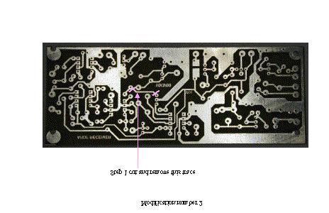
12 Tape pointing in direction of signal. 18- degree ambiguity solved. Figure 12 Megan activating sense and notes that the signal nulls Modifications to receiver since original publication The following modifications are must do modifications that improve the performance of the radio. The Sam Smith gain control modification. To perform the Sam Smith (N4MAP) gain modification first remove Q2,Q4 and all associated components. Next to get VCC connected to the front end, first connect a shorting Jumper between the collector and emitter pins of Q2. This will put the FET front end in normal operational mode. This stage has enough dynamic range to handle a 3 watt 8 meter ARDF transmitter. Next wire the gain pot as shown per the post modification schematic. This modification provides very good gain control operation. (Note in my version I did not use the 22K resistor, I just connected the bottom of the pot to ground.) Page 12
13 Schematic showing receiver front end before modification. Note Q2 and Q4 and associated components. Remove these parts and rewire per the after modification schematic. vcc R11 27 T5-2 Core 32T 6.2 Volt D1 D1N4735 C19 125pf C Pf T1 3T C U4 ina inb vcc osca 8 7 C17 df_loop1 C25 Q1 MPF12 SEE TEXT C24 3 gnd oscb outa outb df_loop2 C29 68pf C pf 51Pf R13 1k R14 22 C3 1Uf R12 1 C28 NE62A IF To AUDIO Sheet High freq limit adjust sense_sw_2 sense_sw_1 vcc C33 1uf sense_loop1 sense_loop2 Fixed Adjustment SENSE GAIN SENSE ENABLE v_rf_stage sense R16 1K Q2 2N2222A C35 2pf Q3 MPF12 C34.22uf R17 5.1k R19 1k Q4 R18 2.2k To AUDIO Sheet MC135_GAIN gain1 2N2222 R2 1Meg R21 1K C37 gain2 PREAMP GAIN R22 47k Schematic showing receiver front end after modification. (Also refer to post modification IF diagram for gain control pot connections) 32T C19 125pf C Pf T1 3T C21 df_loop1 C25 Q1 MPF12 SEE TEXT df_loop2 C29 68pf C pf 51Pf R13 1k R14 22 C3 1Uf R12 1 C28 sense_loop1 sense_loop2 Fixed Adjustment SENSE GAIN sense_sw_2 sense_sw_1 SENSE ENABLE vcc C33 1uf sense R16 1K C35 2pf C34.22uf Q3 MPF12 R2 1Meg R21 1K C37 Page 13


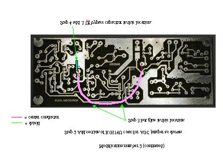
14 The next modifications are a series of VFO stage modifications to correct a board layout error and IF stage modifications to workaround the FAR circuit board layout LO feed through problem. Page 14

15 Page 15
16 Sam also noted that he added the capacitor C31 to reduce the IF LO mixing problem. My current version is using the series trap circuit on the input to the IF. I plan to investigate making the IF stage a tuned amplifier instead to the wide band version in the schematic. This could be accomplished by using an IF transformer in the output circuit of the MC135. This would be the preferred solution to the problem. LO leakage is being amplified by this stage and mixing with the BFO to produce the offending signal at HF. There is another signal that appears around 364Khz. This is the 8 th harmonic of the BFO. Its far enough from the hunt frequency and shouldn t cause a problem. Additional shielding of the BFO stage and filtering of the VCC to the BFO stage could be a possible solution in eliminating it. IF stage before modification vcc R4 22 C1 1uf L3 IF AMP C2 15uH From RCVR Sheet IF FL1 455KHZ TK233-ND U1 1 OUT- OUT+ 8 2 VCC GND 7 3 GND1 IN+ 6 4 IN- AGC 5 MC135 C11 C4 C9 R6 47 C8 IN OUT GND R9 1.5k MC135_GAIN From RCVR Sheet Page 16
17 IF stage After modification (Note the direct connections for the gain control pot. This was part of the gain control modification.) vcc C2 R4 22 C1 1uf L3 15uH IF AMP BFO & PROD DET C3 From RCVR Sheet IF 455KHZ FL1 TK233-ND IN GND OUT C11 R9 1.5k U1 1 OUT- OUT VCC GND1 IN- GND IN+ AGC MC135 C38 L5 15uH 5-35Pf WB8WFK series trap circuit mod. C4 C31 C9.15Uf R6 47 C U2 ina inb gnd vcc osca oscb 4 5 outa outb NE62A This is the cap that Sam added in his version. Do not use if the WB8WFK series trap circuit is used vcc Series trap Modification by WB8WFK to reduce even further the leakage from the LO in the circuit board version pot1 pot2 pot3 R19 22k Modification by Sam Smith to kill the gain of the IF at HF Page 17
18 WB8WFK Voltage regulator modification I also made another modification that replaces the Zener diode regulator circuit with a low drop out regulator. This provided much improved operation over the battery life. The Zener does not regulate very well as the battery voltage goes down with use. However the LDO regulator does a very good job. To perform this circuit modification remove D1, R11 and R5 then install the new regulator circuit per the schematic. Also note that the 1uf capacitor on the regulator output is required. Without it the voltage regulator will oscillate. Original voltage regulator circuit vcc R11 27 R Volt D1 D1N4735 To AUDIO Sheet NE62_REG U4 1 ina vcc 8 2 inb osca 7 3 gnd oscb 6 4 outa outb 5 NE62A IF To AUDIO Sheet High freq limit adjust C17 1k R23 C18 47pf C23 47pf freq2 freq3 freq1 Page 18
19 Modified voltage regulator circuit vcc U5 LM2936Z-5. TO-92 1 Vin VOUT 3 NE62_REG To AUDIO Sheet LM2936Z-5. GND 2 C39 1uf 32T R12 1 T1 SEE TEXT 3T C28 C21 C24 U4 1 ina vcc inb gnd outa osca oscb outb NE62A IF To AUDIO Sheet High freq limit adjust C17 1k R23 C18 47pf C23 47pf freq2 freq3 freq1 Parts list A parts list can be downloaded from the foxfinder web page. Who has built Foxfinders? This section contains information about other individuals or clubs that has built and used this receiver. I want this to become a living document and welcome inputs for this section. Add photos and info about Albuquerque builds Georgia Radio Orienteering Club The Georgia radio orienteering club under the direction of Sam Smith, N4MAP did a large group build of the Foxfinder-8. A very nice write up is located on there website. It is located at the following URL: To date this is the largest group build of this design that has occurred. They report good results and this was the receiver used by the Georgia Radio Orienteering Club on the 8-meter hunt during the USA 21 ARDF championships near Albuquerque. Add info about any California builds Any others? Page 19
20 Page 2
The ROSE 80 CW Transceiver (Part 1 of 3)
") Build a 5 watt, 80 meter QRP CW Transceiver!!! Page 1 of 10 The ROSE 80 CW Transceiver (Part 1 of 3) Build a 5 watt, 80 meter QRP CW Transceiver!!! (Designed by N1HFX) A great deal of interest has been
Build a 5 watt, 80 meter QRP CW Transceiver!!! Page 1 of 10 The ROSE 80 CW Transceiver (Part 1 of 3) Build a 5 watt, 80 meter QRP CW Transceiver!!! (Designed by N1HFX) A great deal of interest has been
S-RockMite QRP Kit User Manual. Welcome to visit the home page to obtain the latest data. 1 / 23. Revision V161101
 S-RockMite QRP Kit User Manual Revision V161101 Welcome to visit the home page www.lxqqfy.com to obtain the latest data. 1 / 23 1. Introduction This is a very small volume of simple 40 meter band micro-power
N3ZI Kits General Coverage Receiver, Assembly & Operations Manual (For Jun 2011 PCB ) Version 3.33, Jan 2012
 Version 3.33, Jan 2012") N3ZI Kits General Coverage Receiver, Assembly & Operations Manual (For Jun 2011 PCB ) Version 3.33, Jan 2012 Thank you for purchasing my general coverage receiver kit. You can use the photo above as a
N3ZI Kits General Coverage Receiver, Assembly & Operations Manual (For Jun 2011 PCB ) Version 3.33, Jan 2012 Thank you for purchasing my general coverage receiver kit. You can use the photo above as a
Beta-test ED1 PCB installed in I0CG s K1
 K1 SSB Modification (Ed.2) This description provides the receiver (RX) modifications, assembly, alignment and operation as a first step. In a second step you can add the remaining transmitter (TX) modifications,
Hendricks QRP Kits BITX20A to BITX17A Conversion Instructions
 Hendricks QRP Kits BITX20A to BITX17A Conversion Instructions 30 November 2008 Converting your BITX20A Kit to a BITX17A Kit is not all that complex. It only requires that you change crystals and some resonance
S Pixie QRP Kit User Manual. Welcome to visit the home page to obtain the latest data. 1 / 24. Revision V160515
 S-Pixie QRP Kit User Manual Revision V160515 Welcome to visit the home page www.lxqqfy.com to obtain the latest data. 1 / 24 1. Introduction PIXIE is a very small volume of simple 40 meter band micro-power
Parallel Port Relay Interface
 Parallel Port Relay Interface Below are three examples of controlling a relay from the PC's parallel printer port (LPT1 or LPT2). Figure A shows a solid state relay controlled by one of the parallel port
ASSEMBLY MANUAL FOR R3500D DIRECTION FINDING RECEIVER KIT
 SDR-Kits www.sdr-kits.net SDR-Kits is CRKITS Authorised Distributor for Europe ASSEMBLY MANUAL FOR R3500D DIRECTION FINDING RECEIVER KIT Rev. A May 24, 2015 Written by CRKITS http://www.crkits.com Thanks
Read This Page First
 Read This Page First If you are reading this you know the manuals are always available at QRPKITS.com. This is version 8.0 of the manual dated 4/27/2016. There is no need to print out the whole assembly
ssb transceiver single-band using the LM373 communications IC
 single-band ssb transceiver using the LM373 communications IC How to use the versatile LM373 and several other ICs to build a compact ssb transceiver for 14 MHz About two years ago a new products announcement
ECE 404 e-notes...copyright 2008 by Gregory M. Wierzba. All rights reserved...fall 2008.
 ECE 404L: RF ELECTRONICS LABORATORY DEPARTMENT OF ELECTRICAL AND COMPUTER ENGINEERING MICHIGAN STATE UNIVERSITY I. TITLE: Lab III - AM/FM Radio - AM Radio II. PURPOSE: This lab will focus on soldering
S-Pixie QRP Kit. Student Manual. Revision V 1-0
 S-Pixie QRP Kit Student Manual Revision V 1-0 Introduction The Pixie 2 is a small, versatile radio transceiver that is very popular with QRP (low power) amateur radio operators the world over. It reflects
K1EL 75 Meter AM Phone Receiver AMR75
 Features 3.8MHz Amateur Phone Band Receiver 100 KHz Tuning Range Wideband Hi-Fi AM mode reception Single Sideband mode with on board BFO Uses single chip TRF TA7642 IC Low impedance 8 ohm speaker output
HF Receivers, Part 2
 HF Receivers, Part 2 Superhet building blocks: AM, SSB/CW, FM receivers Adam Farson VA7OJ View an excellent tutorial on receivers NSARC HF Operators HF Receivers 2 1 The RF Amplifier (Preamp)! Typical
MFJ-249B HF/VHF SWR ANALYZER
 TABLE OF CONTENTS MFJ-249B... 2 Introduction... 2 Powering The MFJ-249B... 3 Battery Installation... 3 Alkaline Batteries... 3 NiCd Batteries... 4 Power Saving Mode... 4 Operation Of The MFJ-249B...5 SWR
Assembly Manual for VFO Board 2 August 2018
 Assembly Manual for VFO Board 2 August 2018 Parts list (Preliminary) Arduino 1 Arduino Pre-programmed 1 Faceplate Assorted Header Pins Full Board Rev A 10 104 capacitors 1 Rotary encode with switch 1 5-volt
Building a Bitx20 Version 3
 Building a Bitx20 Version 3 The board can be broken into sections and then built and tested one section at a time. This will make troubleshooting easier as any problems will be confined to one small section.
Homebrew and Experimenters Group HF Inductance Bridge (Compiled by VK2TOX)
") Homebrew and Experimenters Group HF Inductance Bridge (Compiled by VK2TOX) There are a number of ways to measure inductances used in construction of RF equipment. One of the most versatile ways is with
Homebrew and Experimenters Group HF Inductance Bridge (Compiled by VK2TOX) There are a number of ways to measure inductances used in construction of RF equipment. One of the most versatile ways is with
LM1868 AM FM Radio System
 LM1868 AM FM Radio System General Description The combination of the LM1868 and an FM tuner will provide all the necessary functions for a 0 5 watt AM FM radio Included in the LM 1868 are the audio power
1. What is the unit of electromotive force? (a) volt (b) ampere (c) watt (d) ohm. 2. The resonant frequency of a tuned (LRC) circuit is given by
 volt (b) ampere (c) watt (d) ohm. 2. The resonant frequency of a tuned (LRC) circuit is given by") Department of Examinations, Sri Lanka EXAMINATION FOR THE AMATEUR RADIO OPERATORS CERTIFICATE OF PROFICIENCY ISSUED BY THE DIRECTOR GENERAL OF TELECOMMUNICATIONS, SRI LANKA 2004 (NOVICE CLASS) Basic Electricity,
Department of Examinations, Sri Lanka EXAMINATION FOR THE AMATEUR RADIO OPERATORS CERTIFICATE OF PROFICIENCY ISSUED BY THE DIRECTOR GENERAL OF TELECOMMUNICATIONS, SRI LANKA 2004 (NOVICE CLASS) Basic Electricity,
ZN414Z, ZN415E, ZN416E AM RADIO RECEIVERS
 GEC PLESSEY [SEMICONDUCTORS ZN414Z, ZN415E, ZN416E AM RADIO RECEIVERS FEATURES Single cell operation (1.1 to 1.6 volt, operating range) Low current consumption 150kHz to 3MHz frequency range (i.e. full
ALX-SSB 5 Band Filter Assembly Manual 19 November 2018
 ALX-SSB 5 Band Filter Assembly Manual 19 November 2018 Contents Theory of Operation:... 1 Figure 1... 2 Parts Included:... 4 Board Overview:... 5 Figure 2... 5 Figure 3... 5 Board Assembly:... 6 Cable
SPECIFICATIONS: Subcarrier Frequency 5.5MHz adjustable, FM Modulated +/- 50KHz. 2nd 11MHz >40dB down from 5.5MHz
 Mini-kits AUDIO / SUBCARRIER KIT EME75 Version4 SPECIFICATIONS: Subcarrier Frequency 5.5MHz adjustable, FM Modulated +/- 50KHz Subcarrier Output 1.5v p-p Output @ 5.5MHz DESCRIPTION & FEATURES: The Notes
GRID DIP METER DESIGN
 GRID DIP METER DESIGN BY G0CWA MAY 2013 This, my next offering of test equipment is an exceptionally useful item of test equipment with many uses, some are listed below. To coin a phrase given to me by
HF Amateur SSB Receiver
 HF Amateur SSB Receiver PCB Set for radio club project http://rhelectronics.net PCB for DIY HF Amateur SSB Receiver 20M The receiver is a simple syperheterodyne type with quartz crystal filter. The circuit
CX7 Troubleshooting Index
 CX7 Troubleshooting Index Modification S/1 Newsletter Guide Board Description A/TO A/TO MODE Intermod V1,12 P4.4 A11 Shut off one 35 MHz osc in receive, done sn 244 A/TO Spur V1,12 P1 Reduce A/TO spur,
Step by Step Building PJ meter ARDF Receiver Kit. CRKITS.COM August 5, 2013
 Step by Step Building PJ-80 80-meter ARDF Receiver Kit CRKITS.COM August 5, 2013 What is ARDF? ARDF is the abbreviation of Amateur Radio Direction Finding, or so called Fox Hunting. If you are looking
Amateur Radio Examination EXAMINATION PAPER No. 275 MARKER S COPY
 01-6-(d) An Amateur Station is quoted in the regulations as a station: a for training new radio operators b using amateur equipment for commercial purposes c for public emergency purposes d in the Amateur
Radio Receivers. Al Penney VO1NO
 Radio Receivers Al Penney VO1NO Role of the Receiver The Antenna must capture the radio wave. The desired frequency must be selected from all the EM waves captured by the antenna. The selected signal is
I'm guessing this is what has made it so no one else could get the circuit to work, I hope this helps.
 Incase I did not mention this else where, the basis of my system to provide random audio bits which the spirits can use to form their voices. The audio bits are from randomly tuning a voltage tunable AM
Bitx Version 3 Linear Amplifier Assembly
 Bitx Version 3 Linear Amplifier Assembly The power supply section has 2 options. 1 - AC input and a higher voltage on the IRF510 and +12 volts to the bitx. 2 - +12 volts applied to both the final and the
Treetop Circuits Owner s Manual for SB-SB-600 Adapter Version 1
 The SB-600 SSB adapter from Treetop Circuits (Fig. 1) is designed specifically as an accessory to the Hammarlund SP-600 series of receivers. It provides enhanced performance on SSB and CW signals, using
Technical Info Doc: Galileo2 A simple Direct Conversion Receiver for 20.1MHZ
 Fox Delta Amateur Radio Projects & Kits FD Galileo2 Technical Info Doc: Galileo2 A simple Direct Conversion Receiver for 20.1MHZ This Project is dedicated to our beloved scientist Galileo: Galileo was
AM/FM-108TK FM_RF_AMP
 V1 is 50 mv at 88Mhz V2 is 7.73 Volts dc o Real circuit has supply voltage of 7.73 due to Ir drop across 220 ohm R25 and 100 ohm R9 Ir25 = (8.85-7.75V)/220 ohm = 5 ma Ir9 = (7.75-7.37V)/100 ohm = 3.8 ma
 file:///c /BoatAnchors/Hammarlund/HQ170A/HQ170SVC.TXT Dear OM: This form is being prepared to provide prompt attention to a complaint as a result of trouble that may be experienced in the field. In addition
ERICSSONZ LBI-39129B MAINTENANCE MANUAL FOR RECEIVER FRONT END MODULE 19D902782G6, G8, G9, G10, G11, G12 DESCRIPTION TABLE OF CONTENTS
 MAINTENANCE MANUAL FOR 19D902782G6, G8, G9, G10, G11, G12 TABLE OF CONTENTS Page DESCRIPTION........................................... Front. Cover SPECIFICATIONS..........................................
Easy Transmitter. Support ETX_REV5_Manual V2.7 Revised
 Easy Transmitter Introduction The Easy Transmitter kit from qrpkits.com provides a basic, crystal controlled transmitter with VXO tuning to provide a small tuning range around the crystal frequency. It
AM/FM RADIO KIT MODEL AM/FM-108K INTEGRAL CIRCUIT, 9 TRANSISTORS, 4 DIODES. Assembly and Instruction Manual
 AM/FM RADIO KIT MODEL AM/FM-108K INTEGRAL CIRCUIT, 9 TRANSISTORS, 4 DIODES Assembly and Instruction Manual TM Elenco Electronics, Inc. Copyright 2003, 1989 by Elenco TM Electronics, Inc. All rights reserved.
HT-1A Dual Band CW QRP Transceiver. Kit Building Instructions
 HT-A Dual Band CW QRP Transceiver Kit Building Instructions Rev B, July 8, 08 Designed by BD4RG Exclusively distributed by CRKITS.COM and its worldwide distributors Join the group http://groups.io/g/crkits
S Forty 9er QRP Kit User Manual. Welcome to visit the home page to obtain the latest data. 1 / 23. Revision V160604
 S-Forty-9er QRP Kit User Manual Revision V60604 Welcome to visit the home page www.lxqqfy.com to obtain the latest data. / 3 . Introduction This is a very small volume of simple 40 meter band micro-power
Technician Licensing Class. Lesson 4. presented by the Arlington Radio Public Service Club Arlington County, Virginia
 Technician Licensing Class Lesson 4 presented by the Arlington Radio Public Service Club Arlington County, Virginia 1 Quiz Sub elements T6 & T7 2 Good Engineering Practice Sub element T8 3 A Basic Station
PRACTICE. Amateur Radio Operator Certificate Examination. Advanced Qualification
 Amateur Radio Operator ertificate Examination Advanced Qualification 2019-04-03 To pass this exam, you must correctly answer 35 out of 50 questions Exam Number: 115916 1. (A-007-008-002) Why would one
Module 8 Theory. dbs AM Detector Ring Modulator Receiver Chain. Functional Blocks Parameters. IRTS Region 4
 Module 8 Theory dbs AM Detector Ring Modulator Receiver Chain Functional Blocks Parameters Decibel (db) The term db or decibel is a relative unit of measurement used frequently in electronic communications
Yana Dongles Tom Berger K1TRB (c)2016 v171227
2016 v171227") Yana Dongles Tom Berger K1TRB (c)2016 v171227 These notes elaborate some items described in the Build notes, and add some more dongles enhancing Yana. Every effort has been exerted to save on the cost
Yana Dongles Tom Berger K1TRB (c)2016 v171227 These notes elaborate some items described in the Build notes, and add some more dongles enhancing Yana. Every effort has been exerted to save on the cost
A 75-Watt Transmitter for 3 Bands Simplified Shielding and Filtering for TVI BY DONALD H. MIX, W1TS ARRL Handbook 1953 and QST, October 1951
 A 75-Watt Transmitter for 3 Bands Simplified Shielding and Filtering for TVI BY DONALD H. MIX, W1TS ARRL Handbook 1953 and QST, October 1951 The transmitter shown in the photographs is a 3-stage 75-watt
The Walford Electronics Ford Receiver Kit Project Construction Manual
 The Walford Electronics Ford Receiver Kit Project Construction Manual Walford Electronics Ford Receiver construction manual V1.5 Page 1 of 22 Introduction The Ford receiver has four stages: The first stage
Hendricks QRP Kits The Twofer Rev
 Hendricks QRP Kits The Twofer Rev 1 11-15-06 1. Description The Twofer is a classic QRP transmitter that s easy to assemble and operate. It uses a JFET VXO (variable crystal oscillator), driver stage and
Radio Receivers. Al Penney VO1NO
 Radio Receivers Role of the Receiver The Antenna must capture the radio wave. The desired frequency must be selected from all the EM waves captured by the antenna. The selected signal is usually very weak
: Hacking Bitx Version3B, C: : 20mt to 40mt band: PART I
 : Hacking Bitx Version3B, C: : 20mt to 40mt band: PART I Fig 1: Bitx Ver3C SBL-1 20 Conversion for Bitx40 The picture in Fig1 is a Bitx3C SBL-1 for 40mt band, constructed from the Bitx Version 3C SBL-1
THE 1956 ZENITH ROYAL 500 TRANSISTOR OWL S EYES RADIO.
 THE 1956 ZENITH ROYAL 500 TRANSISTOR OWL S EYES RADIO. Dr. H. Holden. Feb. 2018. Introduction: The Zenith Royal 500 radio appeared in 1956, two years later than the Regency TR1 which was the first commercial
MFJ-203 Bandswitched Dip Meter
 MFJ-203 Bandswitched Dip Meter Thank you for purchasing the MFJ-203 Bandswitched Dip Meter. The MFJ-203 Bandswitched Dip Meter is a solid state bandswitched adaptation of the traditional grid dip meter.
The Uniden Grant XL Owners Site
 The Uniden Grant XL Owners Site Modifications page for the Grant XL (For Informational purposes only) The author of this site takes NO responsibility for illegal modifications and/or use of illegally modified
Building and Operating: LF Converter An SA612 based LF up-converter from Jackson Harbor Press
 Introduction: Building and Operating: LF Converter An SA612 based LF up-converter from Jackson Harbor Press The frequencies below the broadcast band are covered by few receivers on the market - those that
Assembly Manual V1R2B-Rev1.0D
 Assembly Manual V1R2B-Rev1.0D for 4 State QRP MagicBox - Solid State Transmit/Receive System Designed by: Jim Kortge, K8IQY Copyright 2009-2012 - All rights reserved This system is the result of some brainstorming
Building the Sawdust Regenerative Receiver
 Building the Sawdust Regenerative Receiver Introduction The Sawdust is a super regenerative receiver using the basic Armstrong design architecture. The receiver uses one toroidal transformer to provide
Operation Manual. Model SG Elenco Precision Wide Band Signal Generator
 99 Washington Street Melrose, MA 02176 Phone 781-665-1400 Toll Free 1-800-517-8431 Visit us at www.testequipmentdepot.com Elenco Precision Wide Band Signal Generator Model SG-9000 Operation Manual CONTENTS
ADDENDUM NUMBER 2 TO MAINTENANCE MANUAL LBI-38673J Refer to ECO#
 ADDENDUM NUMBER 2 TO MAINTENANCE MANUAL Refer to ECO#20043005 GENERAL This addendum documents a change to the RX Front End Module (19D902782G3, G4, & G7) Maintenance Manual. Torque specification changed
LBI-38673F MAINTENANCE MANUAL FOR RECEIVER FRONT END MODULE 19D902782G3, G4, & G7 DESCRIPTION TABLE OF CONTENTS
 MAINTENANCE MANUAL FOR 19D902782G3, G4, & G7 TABLE OF CONTENTS Page DESCRIPTION........................................... Front Cover SPECIFICATIONS......................................... 1 CIRCUIT
LM1866 Low Voltage AM FM Receiver
 LM1866 Low Voltage AM FM Receiver General Description The LM1866 has been designed for high quality battery powered medium wave AM and FM receiver applications requiring operation down to 3V The AM section
REDSUN PF2100 PLL RADIO OPERATING MANUAL
 REDSUN PF2100 PLL RADIO OPERATING MANUAL TRANSLATED BY LIYPN ALL RIGHTS RESERVED JUNE 2006 (We are the copyright holder of this manual in English. Please do NOT distribute this manual in any form nor post
RECEIVER TEST OSCILLATOR Rev G, January 16, 2018 Copyright 2018, Elecraft, Inc., All Rights Reserved
 E L E C R A F T XG RECEIVER TEST OSCILLATOR Rev G, January 6, 08 Copyright 08, Elecraft, Inc., All Rights Reserved Introduction The Elecraft XG is a crystal oscillator with accurate µv and 50 µv output
S WAMING QRP Kit User Manual. Welcome to visit the home page to obtain the latest data. 1 / 23. Revision 2.1
 S-WAMING QRP Kit User Manual Revision 2.1 Welcome to visit the home page www.lxqqfy.com to obtain the latest data. 1 / 23 1. Introduction This is a very small volume of simple 40 meter band micro-power
Construction Manual 4m-Linear-Transverter XV4-15
 Construction Manual 4m-Linear-Transverter XV4-15 Holger Eckardt DF2FQ Kirchstockacherstr. 33 D-85662 Hohenbrunn 3207 Technical data exciter frequency: 21.0... 21.5 MHz RF frequency: 70.0.. 70.5 MHz supply
Handy dandy little circuit #17 #17
 Handy dandy little circuit #17 #17 Download # 17 in PDF There are a lot of alarm systems on the market but you might be inclined to build your own. This little project can be put together using inexpensive
HAMTRONICS RWWV RECEIVER: INSTALLATION, OPERATION, & MAINTENANCE
 HAMTRONICS RWWV RECEIVER: INSTALLATION, OPERATION, & MAINTENANCE GENERAL INFORMATION. The RWWV is a compact, dedicated receiver module for reception of the 10.000 MHz WWV time and frequency standard broadcasts
LBI-38673C MAINTENANCE MANUAL FOR RECEIVER FRONT END MODULE 19D902782G3, G4, & G7 DESCRIPTION TABLE OF CONTENTS
 LBI-38673C MAINTENANCE MANUAL FOR 19D902782G3, G4, & G7 TABLE OF CONTENTS Page DESCRIPTION........................................... Front Cover SPECIFICATIONS.........................................
Sweep / Function Generator User Guide
 I. Overview Sweep / Function Generator User Guide The Sweep/Function Generator as developed by L. J. Haskell was designed and built as a multi-functional test device to help radio hobbyists align antique
Amateur Radio Examination EXAMINATION PAPER No. 276 MARKER S COPY
 01-3-(a) The Amateur Service in New Zealand is administered through this prime document: a the New Zealand Radiocommunications Regulations b the Broadcasting Act c the Telecommunications Act d the Radio
12kHz LIF Converter V2.43 9Mhz version
 12kHz LIF Converter V2.43 9Mhz version Please Note: This document supersedes all previously released documents and drawings on the LIF subject. This is the latest and most up-to-date document at this time.
! February 9, 1970 GR-78!! Bulletin No: Transistor General Coverage Rcvr!
 ! February 9, 1970 GR-78-1! Rocker Switches [PN 60-45] S.P.S.T. switch is being replaced by [PN 60-48] D.P.D.T. switch with improved contacts. Four of the six lugs are removed when it is used as a S.P.S.T.
LBI-30398N. MAINTENANCE MANUAL MHz PHASE LOCK LOOP EXCITER 19D423249G1 & G2 DESCRIPTION TABLE OF CONTENTS. Page. DESCRIPTION...
 MAINTENANCE MANUAL 138-174 MHz PHASE LOCK LOOP EXCITER 19D423249G1 & G2 LBI-30398N TABLE OF CONTENTS DESCRIPTION...Front Cover CIRCUIT ANALYSIS... 1 MODIFICATION INSTRUCTIONS... 4 PARTS LIST AND PRODUCTION
A 40m Direct Conversion Receiver project to upgrade from ZR to ZS
 A 40m Direct Conversion Receiver project to upgrade from ZR to ZS Hannes Coetzee, ZS6BZP, B.Eng Elektronic (Pretoria) A simple receiver with a low component count is described for the 40m Amateur band.
A homebrew QRP Transceiver. Lots of Fun & Lessons Learnt
 A homebrew QRP Transceiver Lots of Fun & Lessons Learnt Background In 2008 I was transferred to a new location. I could bring 2 suitcases along and spent 5 months in an apartment until the container with
AN1995 Evaluating the SA605 SO and SSOP demo-board
 RF COMMUNICATIONS PRODUCTS Evaluating the SA605 SO and SSOP demo-board Alvin K. Wong 997 Oct 9 Philips Semiconductors Author: Alvin K. Wong INTRODUCTION With the increasing demand for smaller and lighter
The New England Radio Discussion Society electronics course (Phase 4, cont d) Introduction to receivers
 Introduction to receivers") The New England Radio Discussion Society electronics course (Phase 4, cont d) Introduction to receivers AI2Q April 2017 REVIEW: a VFO, phase-locked loop (PLL), or direct digital synthesizer (DDS), can
The New England Radio Discussion Society electronics course (Phase 4, cont d) Introduction to receivers AI2Q April 2017 REVIEW: a VFO, phase-locked loop (PLL), or direct digital synthesizer (DDS), can
E-200D ALIGNMENT. See the end of the procedure for the location of the calibration points. EQUIPMENT REQUIRED
 E-200D ALIGNMENT NOTE: This is not an official B&K alignment procedure. This procedure was created by experimenting with an E-200D. However when this procedure is followed, the resulting calibration should
Build a 12/17 Meter Trap Dipole Phil Salas AD5X
 Build a 12/17 Meter Trap Dipole Phil Salas AD5X Introduction Why a 12/17 meter rotatable dipole? Well, many folks have verticals for the lower bands, and multi-band dipoles or beams for 20-, 15-, and 10
Build this Direct Digital Synthesizer "Development Kit" By: Diz Gentzow, W8DIZ
 Build this Direct Digital Synthesizer "Development Kit" By: Diz Gentzow, W8DIZ A great tutorial for adding a keypad to the DDS Kit by Bruce, W8BH This manual has been prepared to be read directly on screen.
FREQUENCY AGILE FM MODULATOR INSTRUCTION BOOK IB
 FMT615C FREQUENCY AGILE FM MODULATOR INSTRUCTION BOOK IB1215-02 TABLE OF CONTENTS SECTION SUBJECT 1.0 Introduction 2.0 Installation & Operating Instructions 3.0 Specification 4.0 Functional Description
WA3RNC 30 METER CRYSTALPLEXER TRANSMITTER KIT ASSEMBLY INSTRUCTIONS
 WA3RNC 30 METER CRYSTALPLEXER TRANSMITTER KIT ASSEMBLY INSTRUCTIONS Description The WA3RNC 30 Meter Crystalplexer is a low power crystal controlled QRP transmitter offering a significantly improved tuning
Dual Band Filter Assembly Manual
 Dual Band Filter Assembly Manual 12 January 2018 Rev D Version Theory of Operation: The purpose of a Bandpass Filter is to filter out or reject all unwanted signals. The original KN-Q7A Receive Filter
75 Meter SSB Project Design by KD1JV Built by Paul Jorgenson KE7HR NSS 39382FE
 75 Meter SSB Project Design by KD1JV Built by Paul Jorgenson KE7HR NSS 39382FE After completing a 75 meter DSB project (and using it underground, caving), I wanted to try building a SSB rig. I was searching
Building the Sawdust Regenerative Receiver
 Building the Sawdust Regenerative Receiver Introduction The Sawdust is a super regenerative receiver using the basic Armstrong design architecture. The receiver uses one toroidal transformer to provide
For the filter shown (suitable for bandpass audio use) with bandwidth B and center frequency f, and gain A:
 with bandwidth B and center frequency f, and gain A:") Basic Op Amps The operational amplifier (Op Amp) is useful for a wide variety of applications. In the previous part of this article basic theory and a few elementary circuits were discussed. In order to
Basic Op Amps The operational amplifier (Op Amp) is useful for a wide variety of applications. In the previous part of this article basic theory and a few elementary circuits were discussed. In order to
Technical Bulletin A Versatile Pulse Tester Page 1 of 6
 Technical Bulletin A Versatile Pulse Tester Page 1 of 6 A Versatile Pulse Tester By G8MNY (BATC's CQTV No 195, Updated Oct 07) (8 Bit ASCII Graphics use code page 437 or 850) This tester based on ideas
Improving the Performance of the KSB2
 Introduction Improving the Performance of the KSB2 John Grebenkemper, KI6WX KI6WX@pacbell.net July 18, 2002 The following is a set of changes that I have done to my KSB2 and related circuits to improve
Quadrature Upconverter for Optical Comms subcarrier generation
 Quadrature Upconverter for Optical Comms subcarrier generation Andy Talbot G4JNT 2011-07-27 Basic Design Overview This source is designed for upconverting a baseband I/Q source such as from SDR transmitter
BITX40 with Raduino - tips and mods
 BITX40 with Raduino - tips and mods Also check out hfsigs blogspot http://bitxhacks.blogspot.co.uk/ Clicks during tuning I assume you are talking about the Raduino clicking as you tune. I'm not having
1 TRANSISTOR CIRCUITS
 FM TRANSMITTERS The first group of circuits we will discuss are FM TRANSMITTERS. They can be called SPY TRANSMITTERS, FM BUGS, or a number of other interesting names. They all do the same thing. They transmit
ERICSSONZ LBI-30398P. MAINTENANCE MANUAL MHz PHASE LOCKED LOOP EXCITER 19D423249G1 & G2 DESCRIPTION TABLE OF CONTENTS
 MAINTENANCE MANUAL 138-174 MHz PHASE LOCKED LOOP EXCITER 19D423249G1 & G2 TABLE OF CONTENTS Page DESCRIPTION... Front Cover CIRCUIT ANALYSIS...1 MODIFICATION INSTRUCTIONS...4 PARTS LIST...5 PRODUCTION
(12) Patent Application Publication (10) Pub. No.: US 2002/ A1
 Patent Application Publication (10) Pub. No.: US 2002/ A1") (19) United S tates US 20020003503A1 (12) Patent Application Publication (10) Pub. No.: US 2002/0003503 A1 Justice (43) Pub. Date: Jan. 10, 2002 (54) TWIN COILA NTENNA (76) Inventor: Christopher M. Justice,
(19) United S tates US 20020003503A1 (12) Patent Application Publication (10) Pub. No.: US 2002/0003503 A1 Justice (43) Pub. Date: Jan. 10, 2002 (54) TWIN COILA NTENNA (76) Inventor: Christopher M. Justice,
A GOOD REGENERATIVE RECEIVER WITH SIMPLE FINE TUNING (2008)
") A GOOD REGENERATIVE RECEIVER WITH SIMPLE FINE TUNING (2008) A good SSB-CW-AM regenerative receiver with a fine tuning by moving the wooden stick with a grounded piece of PCB towards the coil. A good regenerative
A GOOD REGENERATIVE RECEIVER WITH SIMPLE FINE TUNING (2008) A good SSB-CW-AM regenerative receiver with a fine tuning by moving the wooden stick with a grounded piece of PCB towards the coil. A good regenerative
QEG Instructions for Engineers
 QEG Instructions for Engineers By James Robitaille FTW QEG Engineering Artist -Exciter Coil -Tuning -Core Conditioning -Power Conversion Greetings and Blessings to all our supporters! In lieu of the fact
Frequency range: BAND RANGE MHz MHz
 INSTRUCTION SHEET NO. 20 POWER-MITE PM3 and PM3A DESCRIPTION The Power-Mite 3 and 3A are self-contained CW transceivers covering 40 and 20 meters. The receiver is compromised of a variable oscillator operating
Single Conversion LF Upconverter Andy Talbot G4JNT Jan 2009
 Single Conversion LF Upconverter Andy Talbot G4JNT Jan 2009 Mark 2 Version Oct 2010, see Appendix, Page 8 This upconverter is designed to directly translate the output from a soundcard from a PC running
THE INTERMEDIATE VFO
 THE INTERMEDIATE VFO Some Intermediate tutors have reported difficulties in either obtaining parts for the RSGB Intermediate textbook VFO or in getting the VFO going once they have the parts. This alternative
KWM-2/2A Transceiver THE COLLINS KWM-2/2A TRANSCEIVER
 KWM-2/2A Transceiver Click the photo to see a larger photo Click "Back" button on browser to return Courtesy of Norm - WA3KEY THE COLLINS KWM-2/2A TRANSCEIVER Unmatched for versatility, dependability and
LNB and its ham radio usage
 http://ea4eoz.blogspot.gr/2012/09/lnb-and-its-ham-radio-usage.html LNB and its ham radio usage The letters LNB means Low Noise Block, but we must call it LNC, this is Low Noise Converter, because a LNB
Reconstructing my Hallicrafters SX-28A. John Staples, W6BM
 February 2017 Reconstructing my Hallicrafters SX-28A John Staples, W6BM I say reconstructing instead of recapping because in my youthful ignorance, I took a perfectly good receiver, stripped it and rebuilt
RadiØKit Μ CW HAM RADIO TRANSCEIVER KIT. Assembly and operating manual
 RadiØKit-120 20Μ CW HAM RADIO TRANSCEIVER KIT Assembly and operating manual Boreiou Ipirou 78 Kolonos Athens- Greece - 10444 Tel: 210.5150527 210.5132673 www.freebytes.com Thank you for buying RadiØKit-1,