Abstract: Stringent system specifications impose tough performance requirements on the RF and microwave cables used in aerospace and defense
|
|
|
- Cameron Bradley
- 6 years ago
- Views:
Transcription
1 1
2 Abstract: Stringent system specifications impose tough performance requirements on the RF and microwave cables used in aerospace and defense communication systems. With typical tools, it can be very difficult to perform rigorous testing of the long cables installed in ships and aircraft. This paper presents multiple ways to efficiently and effectively test in situ RF and microwave cables. It also provides useful comparisons for your consideration: different types of solutions; solution cost and complexity versus performance benefits; and measurement range and uncertainty of the various solutions. 2

3 Cable measurements are required to verify and troubleshoot the electrical performance of RF and microwave transmission systems. Measurements are made on coaxial cables or waveguide systems. During the installation, operation and maintenance of an RF or microwave system, the connecting cables may become damaged or show reduced performance over time. Therefore these cables need to be tested. 3

4 Here are three common techniques used today that can be used to measure the insertion loss of a cable or transmission line. The traditional 2-port method, shown on the left, is the configuration to use when both ends of the cable are accessible. This configuration will result in the highest measurement accuracy as a full 2-port calibration can be used to remove all measurement errors associated with adapters and jumper cables required for the test. The center configuration shows a technique for measuring the insertion loss from only one end of the cable. Often when a long cable is installed into a system, it is difficult to physically connect a network analyzer to both ends without introducing an equally long jumper cable into the test setup. Fortunately, the 1-port cable loss technique will eliminate the need to carry an extra-long, high-quality test cable as part of the equipment requirements for on-site testing. This simple 1- port configuration requires a single connection to one end of the cable and leaving the other end either open or terminated in a short. It is preferred at microwave frequencies to use a shorted termination to eliminate fringing fields found in an open-ended cable which could alter the measured results. In this configuration, the VNA measures the S11 of the cable and calculates the one-way insertion loss from the two-way reflected measurement. This technique is ideal for cables whose insertion loss is less than 30 db. When the insertion loss is larger than 30 db, the dynamic range of the test system begins to reduce the accuracy of the measurement. The Power Sensor method is the configuration for measuring cable loss and requires that both ends of the cable be accessible. Here the RF/microwave signal from the source enters one end of the cable and the attenuated signal is measured at the other end using an average power. While considered better than 1-Port measurements for Long Cables (>20m), this technique is limited by low dynamic range of Power Sensor, risks of external interference (settling time) during measurements and needs a Normalization Calibration before measurements. 4

5 The traditional 2-Port method, shown here, is the configuration for measuring cable loss and requires that both ends of the cable be accessible to the VNA. Here the RF/microwave signal from the VNA is incident upon one end of the cable and the attenuated signal is measured at the other end. The ratio of the signal amplitude leaving the cable to the signal entering the cable is defined as the cable loss. This is the most accurate method as it takes advantage of a VNA s full 2-port error correction ability. 5

6 In this configuration, the VNA injects a test signal into the cable and after the signal passes through the cable, it is reflected from the open end (or shorted end) and returns through the cable a second time. Once the reflected measurement is complete, the VNA, using a built-in model for coaxial cable dispersion and knowing that the measured signal contains twice the cable insertion loss can display the cable insertion loss as a function of frequency. A 1-port cable loss measurement is based on a 1-port return loss measurement. An important factor affecting the accuracy of the cable loss measurement is the difference between return loss and insertion loss of the cable under test. If the cable has excellent return loss (>40 db), then the uncertainty contribution from the return loss of the cable is minimum. However, if the cable s return loss in poor, then it has a significant impact on the 1-port cable loss measurement, and the cable return loss becomes the dominant error term in characterization of the insertion loss. You can enhance the accuracy of the 1-port cable loss measurement by performing a normalization using a load at the end of the cable. Let us look at the two first-order uncertainty terms. (1) The RL uncertainty of the measurement, which you read off the published VNA charts. (2) The cable loss/rl uncertainty, due to the RL of the cable under test. For example, let s say you have a cable with an average cable loss of 5 db. A cable loss of 5 db translates to a 10 db return loss measurement. If you look on the N9912A uncertainty chart, you will see that for a 10 db RL measurement, there is ~0.3 db of error. Now let s say the cable s own RL is 20 db. You have a 20 db error vector, for a 10 db measurement. This translates to a 2.5 to 3 db error. This 2.5 to 3 db error caused by the cable s RL is significantly more than the 0.3 db uncertainty due to the 10 db RL. If you used data-memory with a 40-dB load, then that 20 db effectively becomes 40 db. With a 40 db S11, you end up with +/- 0.3 db of error. You add this 0.3 to the original 0.3, for a total of 0.6 db uncertainty. So one-port cable loss measurements are simple, but the user has to be aware of the decreased measurement accuracy, or use data-memory with a load. 6

7 The Power Sensor method is the configuration for measuring cable loss and requires that both ends of the cable be accessible. Here the RF/microwave signal from the source enters one end of the cable and the attenuated signal is measured at the other end using an average power Power Sensor connected via USB (or USB to LAN Extender). While considered better than 1-Port measurements for Long Cables (>20m), this technique is limited by low dynamic range of Power Sensor. It is also a broadband measurement, so it requires a clean source, or it is susceptible to errors due to harmonics. 7

8 We covered the three common methods to test cable loss in the field: a 2-port VNA measurement, a 1-port VNA measurement, and usage of a power sensor. Now let s look at some challenging scenarios such as on board ships, on aircrafts, or in submarines, where access is very difficult, and the cables need to be measured in-situ. Additionally, these are mission-critical system, so accuracy and repeatability of the measurement is of utmost importance. 8
9 Let s look at some of the difficulties of making measurements in the challenging scenarios. One issue is the long distance between the two cables, which makes it hard to bring the two ports together to where the VNA is located. Many of these cables are part of a larger system that requires tuning, so real time speeds are required, which often is a hassle if a power-sensor based system is used. They need high dynamic range because if you have 200 ft. of RF cable, you will have significant loss, and therefore need a solution with high dynamic range to characterize the loss. Customers using scalar systems would often have to use external amplifiers to increase the dynamic range. High accuracy is needed because these are mission-critical systems and have tight tolerances. It goes without saying that the measurements need to be repeatable in the harsh environments in which they are performed because they are mission-critical systems. 9
10 Today for these challenging environments there are three common solutions: one is a signal generator and power sensors, another is a scalar network analyzer, and last we will be introducing the new system ERTA, or Extended Range Transmission Analysis. These will be explored in the next slides. 10
11 A signal generator-based system to measure loss is very simple and common. It s simply a ratio of two power sensor measurement paths, one which includes the DUT, and one which does not. These systems were made popular by the availability of 200 ft. long power sensor/detector cables. These cables carried DC or low-frequency AC signals, so length was not an issue. One power sensor or detector could be carried to the far end, where the end of the RF transmission line cable was located. These solutions are good solutions, except they are very slow, because of the sensor settling time, and also the dynamic range is limited by the power sensor s range. Finally the source needs to be clean (not as much of an issue if an expensive microwave source was purchased). The solution has some challenges for the difficult environments of onboard ships, or on subs. 11
12 When using a broadband measurement receiver such a power sensor or a scalar detector, it is important to pay attention to source harmonics and their impact on the measurement. Sensors or detectors are inherently broadband devices, that is, they measure all signals, independent of their frequency. Therefore if the source or signal generator has harmonics or other mixing products, those products will be measured by the sensor. Now in some cases a user may want the whole power, independent of the frequency, so in that case a power sensor may be fine. But in most cases a clean CW power is desired. In that case, if the signal generator has harmonics, the errors due to it should be included in the measurement uncertainty. The chart here shows potential errors due to source harmonics. 12

13 One of the most common methods users in ships, aircraft, or submarines have been testing long cables is using scalar network analyzers. These instruments were widely used due to the availability of long lengths of cables for the detectors. Their benefits compared to a power sensor based system was their speed. They were swept frequency measurements, and very fast. They also had the source integrated into the analyzer, so it simplified the setup. The detectors often had very good match, which minimized mismatch errors, a key component of insertion loss uncertainty. There were two downsides to these systems: One that they were big and bulky. Users would have to carry a heavy benchtop piece of equipment into small or compact spaces, and these equipment were designed to be used as benchtop products and had relatively high field failure rates. They were good equipment, but were not designed for the harsh environments encountered in the field. Second issue was that they simply did not have enough dynamic range. So users would often need an external amplifier. The amplifier was another piece of equipment that had to be carried, configured, and broadband microwave amplifiers were very costly. While these scalar solutions provided accurate measurements, they were not ideal solutions. Let s now look at a new solution called Extended Range Transmission Analysis or ERTA, which is based on the use of two handheld analyzers. 13
14 In general a spectrum analyzer is used to characterize unknown signals, but when paired with a built in tracking generator it can measure the scalar transfer of some device under test. These measurements typically proceed faster than general SA frequency scans, as the receiver hops along in lockstep with the source energy, never just scanning empty space. The measured result is similar to a scalar S21, and trace normalization can be used to null out the impact of connecting cables. Extended Range Transmission Analysis enhances this standard SA capability by putting two FieldFox units to work, one acting as Source and the other as Receiver. 14

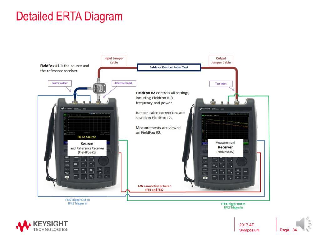
15 The ERTA application is a spectrum analyzer that knows how to synchronize with a partner unit for tracking measurements. The receiver unit acts as master measuring the output of a device under test while the Source unit responds as slave supplying signal at the input. The two instruments can be separated by hundreds of meters, allowing solutions for unique use cases such as long cable characterization. With the proper setup (power splitter), the Source unit uses its own SA receiver to measure the reference signal, thus yielding a true B/R ratio measurement. Along with new dual cable corrections capability, this eliminates the need for static trace normalization, because the reference trace is updated on every sweep. Since each SA Receiver stays accurate with InstAlign, the resulting Scalar S21 Transmission ratio can be trusted even if the units are operating at different temperatures. Handshake signal connections: The trigger/ref OUT port of each unit needs to be connected to the trigger/ref IN port of the other unit. The handshake signals facilitate the essential synchronous measurement stepping to each tune position. LAN communication signals: The units can either be connected directly to each other with a crossover cable, or they can be together on a network thru a switch or router. The LAN allows for SCPI communication between the units to facilitate a master/slave style partnership This configuration is also capable of measuring transmission paths which contain a frequency conversion element such as a frequency downconverter or upconverter. 15
16 ERTA s connection wizard guides the user through the setup process, to ensure a valid connection. After guiding the user through connection the LAN and trigger cables, it verifies that each of these cables has been correctly configured. If not, it will indicate an x on the screen. This provides assurance to the user that their setup is correct. 16
17 FieldFox s ERTA Measurement Wizard guides the user through measuring of jumper cables on the source side and receiver side, or input and output sides, if such cables are part of the system. The loss or S21 magnitude of the cable is measured using the underlying VNA which is part of FieldFox. The calibration that is used is the built-in factory Cal or CalReady, which is an accurate calibration traceable to NIST, done at the test ports. This S21 or cable loss measurement is very accurate and is used in the measurement. If users want to use a different method to characterize the cable, or want to upload an insertion loss measured on a different analyzer, the ERTA GUI allows for that. 17

18 The ERTA GUI allows the user to examine the input power, output power, or Gain (B/R). In most instances, the user is interested in measuring insertion loss or gain (B/R). But during the initial setup, it is useful to observe the input power or output power directly. It is also useful when testing converters, as will be examined later, as the input and output frequencies differ. The annotation on the left side of the screen indicates the measurement (r, B, and B/r = G). 18
19 RF / DUT connections: The preferred setup takes the Source partner signal (port 1) thru a power splitter, returning ½ the power back (port 2) for a reference measurement. The other ½ power is routed thru a connection cable to the DUT. At the output of the DUT a second connection cable brings the transmitted signal back to the Receiver partner (port 2). The preferred setup allows for accurate ratio measurements with specifications. A simplified setup could omit the power splitter, and just route the Source partner s signal thru the DUT and on to the Receiver partner s SA input. The simplified setup would just show nominal transmission response without ratio and without specs. 19

20 An advantage of ERTA is that it uses the spectrum analyzer as the receiver, it has very high dynamic range, which allows it to be used to measure very lossy cables. If you have a short run of a cable, let s say 10 feet, dynamic range is not as critical of an issue, as perhaps you have 5-7 db loss. But when you have long lengths of cable runs, let s say 200 feet, then your loss at microwave frequencies can easily run into the 50+ db range, even 70 or 80 db. In that case, you need test equipment that can measure even better than that. And that s where ERTA comes into play. Some sample dynamic range values for a FieldFox based ERTA system are shown here. For a 50 GHz system, you can measure up to 88 db of loss. That s quite an astounding dynamic range for a portable solution. The plot on the right shows a comparison of a filter measurement using ERTA, compared to a benchtop VNA, and you can see how good ERTA is able to make the measurement. 20
21 Locking the analyzers frequency references to GPS allows for greater frequency accuracy of the FieldFoxes and use of a narrower RBW, which in turn results in a lower DANL, and hence a wider measurement range. When the GPS signals cannot be present at all times, the GPS holdover mode can be used. 21

22 Here are we looking at the impact of different RBWs on the ERTA measurement. Measurement example: 90 db of attenuation with a 60 MHz bandpass filter showing measurement optimization through varying resolution bandwidths after a GPS synchronization. When measuring very high loss devices with ERTA, too wide a RBW will cause errors due to high trace noise and too narrow will cause amplitude degradation due to the two FieldFoxes IF filters no longer being aligned. Note that the sweep time increases significantly as the RBW narrows, requiring longer wait times before measurement data displays. 22
23 This slide summarize the features needed to maximize dynamic range with ERTA on the receiver side, or the receiver analyzer. The RBW can be narrowed which results in a lower noise floor. The attenuation can be reduced to zero. And also the internal preamp can be applied for an additional 15 to 20 db of dynamic range. Lastly as discussed, the units can be locked to GPS to allow for the use of a narrower RBW. 23
24 From the source perspective, an external preamplifier can help increase the net dynamic range. This preamp can be powered off either FieldFox s internal variable voltage source or be a USB (such as the Keysight U7227C) powered preamp. Even though the U7227 is a preamp, its output can achieve ~+13 or +14 dbm, about +10 higher than FieldFox s source output. The U7227C is much more convenient than a benchtop-acpowered amplifier, which is what many users are using today. 24

25 This slide is not specific to ERTA, but just shows general SA improvements with the use of the Keysight USB preamp. But since ERTA is an SA based measurement, it will also see the same improvements. Here we are unable to see a -145 dbm signal with the FieldFox s SA mode, even though the internal preamp is on, and attenuation is set to zero. Once we add the external preamp, we can easily the see signal. So the preamp can be used to increase dynamic range or sensitivity. 25

26 Since the SA is used as the receiver, with a FieldFox configuration, you benefit from InstAlign. InstAlign provides excellent amplitude accuracy. Also, since the SA is tuned only to the frequency of interest, all harmonics or out-of-bound signals are not measured, resulting in a clean measurement. Furthermore, the high dynamic range (low noise floor) contributes to overall accuracy. Even if the dynamic range is not needed, it is useful, as it results in a better S/N ratio, reducing overall noise. 26

27 ERTA adds offset tracking capability to the source. Source offset tracking allows the DUT to contain a frequency translation device, like a mixer or converter, common components in RF subsystems. Source tracking offset provides for a mathematical offset between the Source Freq and Receiver Freq at every tune position if the Source is set to Tracking mode. TrackingOffset OFF (default) SourceFreq = ReceiverFreq TrackingOffset ON, and Reversal OFF: SourceFreq = TrackingOffset + ReceiverFreq TrackingOffset ON, and Reversal ON: SourceFreq = TrackingOffset - ReceiverFreq The spectrum analyzer Amplitude Corrections menu allows for two independent cable responses. The corrections are now called out as either SourceSide or ReceiverSide, to represent cabling on either side of the Device Under Test (DUT). The primary reason for this enhancement is to properly compensate during Offset Tracking measurements, where mapping to unique frequency ranges is necessary depending on the side (source or receiver); however, it is equally valid to characterize two independent cables when Offset Tracking is not enabled. Both corrections are applied on the master FieldFox where final trace processing is performed. Cable Corrections can be setup manually, but there is also a Wizard available under the Cal menu to simplify the setup process. 27

28 The slide shows ERTA with the same summary information as the other methods. ERTA is system that uses two sources. It is useful for measuring a wide range of devices with high dynamic range, and long lengths of cables. It is also very accurate, and simple to use in that no calibration is needed. 28

29 This slide shows a comparison of the different methods we have discussed for insertion loss testing. 29
30 To summarize ERTA is a system designed to measure the insertion loss of in-situ cables over long distances. ERTA requires no open, short, load type calibration, simplifying the measurement setup for the user. It is extremely accurate, taking advantage of FieldFox s InstAlign capability, and the ratioed measurement between source and receiver, which eliminates any errors due to drift. It is a fast measurement system, since it is a spectrum analyzer measurement. It is fast enough to be used for real-time tuning. And lastly, ERTA has been adopted by various departments in the U.S. Department of Defense. ERTA measurements have been compared to previous measurements, and the results have agreed with previous established measurements. 30

31 The FieldFox microwave analyzer is a combination cable/antenna test set, 2-port VNA, spectrum analyzer, power meter, independent source and GPS receiver. It is particularly designed for aerospace and defense communication system field test. Here are a few key features that make FieldFox the ideal tool for field test: 1. VNA, SA, source and power meter in one package 2. No warm up for spectrum analyzer measurements, instalign technology of FieldFox allows the spectrum analyzer to measure spectrum amplitude as accurate as 0.5 db, approaching average power sensor accuracy without warm up. 3. The FieldFox signal source can be set independently, which is ideal for measuring frequency converters. 4. ERTA can be used to measure loss of lengthy cables in-situ. 5. Real-time spectrum analyzer for interference analysis. It is compliant with MIL standards for use in tough environments. It is type tested to use in explosive environments, and it is also type tested for IP53, dust and splash proof. FieldFox is battery powered and can continuously operate for 3.5 hrs. 31
32 32
33 33
34 34
Keysight Technologies FieldFox Handheld Analyzers
 Keysight Technologies FieldFox Handheld Analyzers 4/6.5/9/14/18/26.5/32/44/50 GHz Data Sheet N9913A N9914A N9915A N9925A N9935A N9916A N9926A N9936A N9917A N9927A N9937A N9918A N9928A N9938A N9950A N9951A
Keysight FieldFox Handheld Analyzers
 Keysight FieldFox Handheld Analyzers 4/6.5/9/4/8/26.5 GHz Data Sheet N993A N994A N995A N996A N997A N998A N9925A N9926A N9927A N9928A N9935A N9936A N9937A N9938A Table of Contents Cable and Antenna Analyzer
On site RF troubleshooting for installation and maintenance
 On site RF troubleshooting for installation and maintenance Measure of interferers, high power for microwave links or low power for Base Stations uplink Troubleshooting of cables, or waveguides, and antennas
FieldFox Handheld Education Series Part 3: Calibration Techniques for Precise Field Measurements
 FieldFox Handheld Education Series Part 3: Calibration Techniques for Precise Field Measurements FieldFox Handheld Education Series Interference Testing Cable and Antenna Measurements Calibration Techniques
Keysight FieldFox Handheld Analyzers
 Keysight FieldFox Handheld Analyzers 4/6.5/9/14/18/26.5/32/44/50 GHz Configuration Guide 02 Keysight FieldFox Handheld Analyzers - Configuration Guide The FieldFox Analyzer Family This configuration guide
Keysight Technologies Techniques for Precise Cable and Antenna Measurements in the Field
 Keysight Technologies Techniques for Precise Cable and Antenna Measurements in the Field Using FieldFox handheld analyzers Application Note This application note introduces the practical aspects of cable
Keysight Technologies FieldFox Handheld Analyzers
 Keysight Technologies FieldFox Handheld Analyzers 4/6.5/9/14/18/26.5/32/44/50 GHz Data Sheet N9913A N9914A N9915A N9925A N9935A N9916A N9926A N9936A N9917A N9927A N9937A N9918A N9928A N9938A N9950A N9951A
Understanding RF and Microwave Analysis Basics
 Understanding RF and Microwave Analysis Basics Kimberly Cassacia Product Line Brand Manager Keysight Technologies Agenda µw Analysis Basics Page 2 RF Signal Analyzer Overview & Basic Settings Overview
Configuration of PNA-X, NVNA and X parameters
 Configuration of PNA-X, NVNA and X parameters VNA 1. S-Parameter Measurements 2. Harmonic Measurements NVNA 3. X-Parameter Measurements Introducing the PNA-X 50 GHz 43.5 GHz 26.5 GHz 13.5 GHz PNA-X Agilent
Agilent PNA Microwave Network Analyzers
 Agilent PNA Microwave Network Analyzers Application Note 1408-3 Improving Measurement and Calibration Accuracy using the Frequency Converter Application Table of Contents Introduction................................................................2
FieldFox Handheld Analyzers
 FieldFox Handheld Analyzers 4/6.5/9/14/18/26.5/32/44/50 GHz This configuration guide describes configurations, options and accessories for the FieldFox family of portable analyzers. This guide should be
PXA Configuration. Frequency range
 Keysight Technologies Making Wideband Measurements Using the Keysight PXA Signal Analyzer as a Down Converter with Infiniium Oscilloscopes and 89600 VSA Software Application Note Introduction Many applications
Network Analysis Basics
 Adolfo Del Solar Application Engineer adolfo_del-solar@agilent.com MD1010 Network B2B Agenda Overview What Measurements do we make? Network Analyzer Hardware Error Models and Calibration Example Measurements
Keysight Technologies FieldFox Handheld Analyzers
 Keysight Technologies FieldFox Handheld Analyzers 4/6.5/9/14/18/26.5/32/44/50 GHz Data Sheet N9913A N9914A N9915A N9925A N9935A N9916A N9926A N9936A N9917A N9927A N9937A N9918A N9928A N9938A N9950A N9951A
Keysight Technologies Making Accurate Intermodulation Distortion Measurements with the PNA-X Network Analyzer, 10 MHz to 26.5 GHz
 Keysight Technologies Making Accurate Intermodulation Distortion Measurements with the PNA-X Network Analyzer, 10 MHz to 26.5 GHz Application Note Overview This application note describes accuracy considerations
Keysight Technologies FieldFox Handheld Analyzers
 Keysight Technologies FieldFox Handheld Analyzers 4/6.5/9/14/18/26.5/32/44/50 GHz Data Sheet N9913A N9914A N9915A N9925A N9935A N9916A N9926A N9936A N9917A N9927A N9937A N9918A N9928A N9938A N9950A N9951A
Keysight Technologies Techniques for Precise Power Measurements in the Field
 Keysight Technologies Techniques for Precise Power Measurements in the Field Using FieldFox handheld analyzers Application Note This application note will discuss techniques for measuring average and peak
Agilent 86030A 50 GHz Lightwave Component Analyzer Product Overview
 Agilent 86030A 50 GHz Lightwave Component Analyzer Product Overview 2 Characterize 40 Gb/s optical components Modern lightwave transmission systems require accurate and repeatable characterization of their
FieldFox Handheld Analyzers
 FieldFox Handheld Analyzers 4/6.5/9/14/18/26.5/32/44/50 GHz N9913A N9914A N9915A N9925A N9935A N9916A N9926A N9936A N9917A N9927A N9937A N9918A N9928A N9938A N9950A N9960A N9951A N9961A N9952A N9962A Find
772D coaxial dual-directional coupler 773D coaxial directional coupler. 775D coaxial dual-directional coupler 776D coaxial dual-directional coupler
 72 772D coaxial dual-directional coupler 773D coaxial directional coupler 775D coaxial dual-directional coupler 776D coaxial dual-directional coupler 777D coaxial dual-directional coupler 778D coaxial
Keysight Technologies FieldFox Handheld Analyzers
 Keysight Technologies FieldFox Handheld Analyzers 4/6.5/9/14/18/26.5/32/44/50 GHz Configuration Guide 02 Keysight FieldFox Handheld Analyzers - Configuration Guide The FieldFox Handheld Analyzer Family
External Source Control
 External Source Control X-Series Signal Analyzers Option ESC DEMO GUIDE Introduction External source control for X-Series signal analyzers (Option ESC) allows the Keysight PXA, MXA, EXA, and CXA to control
Keysight Technologies Correlating Microwave Measurements between Handheld and Benchtop Analyzers
 Keysight Technologies Correlating Microwave Measurements between Handheld and Benchtop Analyzers Using FieldFox Handheld Analyzers up to 26.5 GHz Application Note Abstract For the first time, technology
Correlating Microwave Measurements between Handheld and Benchtop Analyzers
 Correlating Microwave Measurements between Handheld and Benchtop Analyzers Using FieldFox handheld analyzers up to 26.5 GHz Application Note For the first time, technology breakthroughs have enabled high-performance
5 ESSENTIAL HINTS TO IMPROVE Millimeter-wave Network Analysis
 5 ESSENTIAL HINTS TO IMPROVE Millimeter-wave Network Analysis Contents 5 Essential Hints to Improve Millimeter-wave Network Analysis Ensure Accurate, Repeatable Results Go to Hint 1 > Calibrate for Better
PARAMETER CONDITIONS TYPICAL PERFORMANCE Operating Supply Voltage 3.1V to 3.5V Supply Current V CC = 3.3V, LO applied 152mA
 DESCRIPTION LT5578 Demonstration circuit 1545A-x is a high linearity upconverting mixer featuring the LT5578. The LT 5578 is a high performance upconverting mixer IC optimized for output frequencies in
Agilent PNA Microwave Network Analyzers
 Agilent PNA Microwave Network Analyzers Application Note 1408-1 Mixer Transmission Measurements Using The Frequency Converter Application Introduction Frequency-converting devices are one of the fundamental
Exercise 5: Power amplifier measurement
 Exercise 5: Power amplifier measurement The objective of this laboratory exercise is the calibrated measurement of important parameters of a power amplifier. This includes performance parameters like gain,
Improving Amplitude Accuracy with Next-Generation Signal Generators
 Improving Amplitude Accuracy with Next-Generation Signal Generators Generate True Performance Signal generators offer precise and highly stable test signals for a variety of components and systems test
Keysight Technologies Ampliier Linear and Gain Compression Measurements with the PNA Microwave Network Analyzers. Application Note
 Keysight Technologies Ampliier Linear and Gain Compression Measurements with the PNA Microwave Network Analyzers Application Note Introduction This application note covers testing of an ampliier s linear
Compact Series: S5065 & S5085 Vector Network Analyzers KEY FEATURES
 Compact Series: S5065 & S5085 Vector Network Analyzers KEY FEATURES Frequency range: 9 khz - 6.5 or 8.5 GHz Measured parameters: S11, S12, S21, S22 Wide output power adjustment range: -50 dbm to +5 dbm
Keysight Technologies PNA-X Series Microwave Network Analyzers
 Keysight Technologies PNA-X Series Microwave Network Analyzers Active-Device Characterization in Pulsed Operation Using the PNA-X Application Note Introduction Vector network analyzers (VNA) are the common
Agilent N9923A FieldFox RF Vector Network Analyzer 2 MHz to 4/6 GHz. Data Sheet
 Agilent N9923A FieldFox RF Vector Network Analyzer 2 MHz to 4/6 GHz Data Sheet Table of Contents Definitions... 2 FieldFox RF Vector Network Analyzer... 3 Cable and Antenna Analyzer (Option 305)... External
Keysight Technologies PNA Microwave Network Analyzers
 Keysight Technologies PNA Microwave Network Analyzers Mixer Conversion-Loss and Group-Delay Measurement Techniques and Comparisons Application Note Table of Contents Introduction... 2 Conversion Loss...
Agilent FieldFox Combination Analyzers
 Agilent FieldFox Combination Analyzers 4/6.5/9/14/18/26.5 GHz Technical Overview N9913A N9914A N9915A N9916A N9917A N9918A Carry precision with you. Get Agilent-quality microwave measurements in the field
PXIe Contents CALIBRATION PROCEDURE
 CALIBRATION PROCEDURE PXIe-5632 This document contains the verification and adjustment procedures for the PXIe-5632 Vector Network Analyzer. Refer to ni.com/calibration for more information about calibration
Agilent FieldFox Handheld Analyzers
 Agilent FieldFox Handheld Analyzers 4/6.5/9/4/8/26.5 GHz Data Sheet N993A N994A N995A N996A N997A N998A N9925A N9926A N9927A N9928A N9935A N9936A N9937A N9938A This data sheet provides the specified and
Overcoming Mixer Measurement Challenges
 Overcoming Mixer Measurement Challenges October 10, 2002 presented by: Robb Myer Dave Ballo Today we will be looking at overcoming measurements challenges associated with frequency translating devices
PLANAR 814/1. Vector Network Analyzer
 PLANAR 814/1 Vector Network Analyzer Frequency range: 100 khz 8 GHz Measured parameters: S11, S12, S21, S22 Wide output power range: -60 dbm to +10 dbm >150 db dynamic range (1 Hz IF bandwidth) Direct
Keysight Technologies FieldFox Handheld Analyzers
 Keysight Technologies FieldFox Handheld Analyzers 4/6.5/9/14/18/26.5/32/44/50 GHz Technical Overview N9913A N9914A N9915A N9925A N9935A N9916A N9926A N9936A N9917A N9927A N9937A N9918A N9928A N9938A N9950A
Agilent 8360B/8360L Series Synthesized Swept Signal/CW Generators 10 MHz to 110 GHz
 Agilent 8360B/8360L Series Synthesized Swept Signal/CW Generators 10 MHz to 110 GHz ity. l i t a ers V. n isio c e r P. y t i l i ib Flex 2 Agilent 8360 Synthesized Swept Signal and CW Generator Family
Precision Validation, Maintenance and Repair of Satellite Earth Stations
 Precision Validation, Maintenance and Repair of Satellite Earth Stations September 18, 2014 Co-sponsored by Keysight Technologies 2014 Tom Hoppin Application Specialist Component Test Division Keysight
Agilent N9343C Handheld Spectrum Analyzer (HSA)
") Test Equipment Depot - 800.517.8431-99 Washington Street Melrose, MA 02176 - TestEquipmentDepot.com Agilent N9343C Handheld Spectrum Analyzer (HSA) 1 MHz to 13.6 GHz (tunable to 9 khz) Data Sheet Field
Test Equipment Depot - 800.517.8431-99 Washington Street Melrose, MA 02176 - TestEquipmentDepot.com Agilent N9343C Handheld Spectrum Analyzer (HSA) 1 MHz to 13.6 GHz (tunable to 9 khz) Data Sheet Field
Keysight FieldFox Combination Analyzers
 Keysight FieldFox Combination Analyzers 4/6.5/9/14/18/26.5 GHz Technical Overview N9913A N9914A N9915A N9916A N9917A N9918A Get Keysight-Quality Microwave Measurements in the Field Every piece of gear
Vector-Receiver Load Pull Measurement
 MAURY MICROWAVE CORPORATION Vector-Receiver Load Pull Measurement Article Reprint of the Special Report first published in The Microwave Journal February 2011 issue. Reprinted with permission. Author:
Precision Validation of Radar System Performance in the Field
 Precision Validation of Radar System Performance in the Field August 19, 2015 Tom Hoppin Application Specialist Component Test Division Keysight Technologies Keysight Technologies 2015 1 Precision Validation
FieldFox Handheld Education Series Part 1: Techniques for Precise Interference Measurements in the Field
 FieldFox Handheld Education Series Part 1: Techniques for Precise Interference Measurements in the Field FieldFox Handheld Education Series Interference Testing Cable and Antenna Measurements Calibration
Keysight Technologies 8 Hints for Making Better Measurements Using RF Signal Generators. Application Note
 Keysight Technologies 8 Hints for Making Better Measurements Using RF Signal Generators Application Note 02 Keysight 8 Hints for Making Better Measurements Using RF Signal Generators - Application Note
Keysight Technologies A comparison of Keysight Network Analyzers for Applications < 3 GHz. Selection Guide
 Keysight Technologies A comparison of Keysight Network Analyzers for Applications < 3 GHz Selection Guide N9923A FieldFox RF Vector Network Analyzer, 2 MHz to 4/6 GHz Keysight Technologies, Inc. handheld
Vector Network Analyzers (VERY) Basics. Tom Powers USPAS SRF Testing Course 19 Jan. 2014
 Basics. Tom Powers USPAS SRF Testing Course 19 Jan. 2014") Vector Network Analyzers (VERY) Basics Tom Powers USPAS SRF Testing Course 19 Jan. 2014 S-Parameters A scattering matrix relates the voltage waves incident on the ports of a network to those reflected
Vector Network Analyzers (VERY) Basics Tom Powers USPAS SRF Testing Course 19 Jan. 2014 S-Parameters A scattering matrix relates the voltage waves incident on the ports of a network to those reflected
Agilent AN Applying Error Correction to Network Analyzer Measurements
 Agilent AN 287-3 Applying Error Correction to Network Analyzer Measurements Application Note 2 3 4 4 5 6 7 8 0 2 2 3 3 4 Table of Contents Introduction Sources and Types of Errors Types of Error Correction
Suitable firmware can be found on Anritsu's web site under the instrument library listings.
 General Caution Please use a USB Memory Stick for firmware updates. Suitable firmware can be found on Anritsu's web site under the instrument library listings. If your existing firmware is older than v1.19,
Keysight Technologies FieldFox Handheld Analyzers
 Keysight Technologies FieldFox Handheld Analyzers 4/6.5/9/14/18/26.5/32/44/50 GHz Configuration Guide 02 Keysight FieldFox Handheld Analyzers - Configuration Guide The FieldFox Handheld Analyzer Family
Keysight Technologies FieldFox Handheld Analyzers
 Keysight Technologies FieldFox Handheld Analyzers 4/6.5/9/14/18/26.5/32/44/50 GHz Configuration Guide 02 Keysight FieldFox Handheld Analyzers - Configuration Guide The FieldFox Handheld Analyzer Family
Hot S 22 and Hot K-factor Measurements
 Application Note Hot S 22 and Hot K-factor Measurements Scorpion db S Parameter Smith Chart.5 2 1 Normal S 22.2 Normal S 22 5 0 Hot S 22 Hot S 22 -.2-5 875 MHz 975 MHz -.5-2 To Receiver -.1 DUT Main Drive
Agilent 4-Port PNA-L Network Analyzers
 Agilent 4-Port PNA-L Network Analyzers N5230A Options 240, 245 300 khz to 20 GHz Speed and accuracy you can count on Integrated 4-port, balanced measurements up to 20 GHz Introducing the 4-port PNA-L network
Keysight Technologies Nonlinear Vector Network Analyzer (NVNA) Breakthrough technology for nonlinear vector network analysis from 10 MHz to 67 GHz
 Breakthrough technology for nonlinear vector network analysis from 10 MHz to 67 GHz") Keysight Technologies Nonlinear Vector Network Analyzer (NVNA) Breakthrough technology for nonlinear vector network analysis from 1 MHz to 67 GHz 2 Keysight Nonlinear Vector Network Analyzer (NVNA) - Brochure
Keysight Technologies Nonlinear Vector Network Analyzer (NVNA) Breakthrough technology for nonlinear vector network analysis from 1 MHz to 67 GHz 2 Keysight Nonlinear Vector Network Analyzer (NVNA) - Brochure
Millimeter Signal Measurements: Techniques, Solutions and Best Practices
 New Network Analyzer platform Millimeter Signal Measurements: Techniques, Solutions and Best Practices Phase Noise measurements update 1 N522XA PNA Series Network Analyzer Introducing Highest Performance
RF and Microwave Test and Design Roadshow 5 Locations across Australia and New Zealand
 RF and Microwave Test and Design Roadshow 5 Locations across Australia and New Zealand Advanced VNA Measurements Agenda Overview of the PXIe-5632 Architecture SW Experience Overview of VNA Calibration
DSA-815 Demo Guide. Solution: The DSA 800 series of spectrum analyzers are packed with features.
 FAQ Instrument Solution FAQ Solution Title DSA-815 Demo Guide Date:08.29.2012 Solution: The DSA 800 series of spectrum analyzers are packed with features. Spectrum analyzers are similar to oscilloscopes..
Test & Calibration Benefits from a New Precision RF/Microwave Calibrator
 Test & Calibration Benefits from a New Precision RF/Microwave Calibrator Topics: RF & Microwave calibration signal requirements Design philosophy and architecture of the new RF Calibrator. Spectrum analyzer
Amplifier Characterization in the millimeter wave range. Tera Hertz : New opportunities for industry 3-5 February 2015
 Amplifier Characterization in the millimeter wave range Tera Hertz : New opportunities for industry 3-5 February 2015 Millimeter Wave Converter Family ZVA-Z500 ZVA-Z325 Y Band (WR02) ZVA-Z220 J Band (WR03)
FieldFox Handheld Education Series Part 7: Precision Validation of Radar System Performance in the Field
 FieldFox Handheld Education Series Part 7: Precision Validation of Radar System Performance in the Field FieldFox Handheld Education Series Interference Testing Cable and Antenna Measurements Calibration
Agilent PN Testing amplifiers and active devices with the Agilent 8510C Network Analyzer. Product Note
 Agilent PN 8510-18 Testing amplifiers and active devices with the Agilent 8510C Network Analyzer Product Note Table of Contents 3 Introduction 4 Amplifier parameters 5 Measurement setup 7 Linear measurements
S3602A/B Vector Network Analyzer Datasheet
 S3602A/B Vector Network Analyzer Datasheet Saluki Technology Inc. The document applies to the vector network analyzers of the following models: S3602A vector network analyzer (10MHz-13.5GHz). S3602B vector
PLANAR R54. Vector Reflectometer KEY FEATURES
 PLANAR R54 Vector Reflectometer KEY FEATURES Frequency range: 85 MHz 5.4 GHz Reflection coefficient magnitude and phase, cable loss, DTF Transmission coefficient magnitude when using two reflectometers
Some Aspects Regarding the Measurement of the Adjacent Channel Interference for Frequency Hopping Radio Systems
 Some Aspects Regarding the Measurement of the Adjacent Channel Interference for Frequency Hopping Radio Systems PAUL BECHET, RADU MITRAN, IULIAN BOULEANU, MIRCEA BORA Communications and Information Systems
Measurements 2: Network Analysis
 Measurements 2: Network Analysis Fritz Caspers CAS, Aarhus, June 2010 Contents Scalar network analysis Vector network analysis Early concepts Modern instrumentation Calibration methods Time domain (synthetic
Keysight Technologies Pulsed Antenna Measurements Using PNA Network Analyzers
 Keysight Technologies Pulsed Antenna Measurements Using PNA Network Analyzers White Paper Abstract This paper presents advances in the instrumentation techniques that can be used for the measurement and
SC5307A/SC5308A 100 khz to 6 GHz RF Downconverter. Datasheet SignalCore, Inc.
 SC5307A/SC5308A 100 khz to 6 GHz RF Downconverter Datasheet 2017 SignalCore, Inc. support@signalcore.com P RODUCT S PECIFICATIONS Definition of Terms The following terms are used throughout this datasheet
Agilent X-Series Signal Analyzer This manual provides documentation for the following X-Series Analyzer: CXA Signal Analyzer N9000A
 Agilent X-Series Signal Analyzer This manual provides documentation for the following X-Series Analyzer: CXA Signal Analyzer N9000A N9000A CXA Functional Tests Notices Agilent Technologies, Inc. 2006-2008
Optoelectronic Components Testing with a VNA(Vector Network Analyzer) VNA Roadshow Budapest 17/05/2016
 VNA Roadshow Budapest 17/05/2016") Optoelectronic Components Testing with a VNA(Vector Network Analyzer) VNA Roadshow Budapest 17/05/2016 Content Introduction Photonics & Optoelectronics components Optical Measurements VNA (Vector Network
Optoelectronic Components Testing with a VNA(Vector Network Analyzer) VNA Roadshow Budapest 17/05/2016 Content Introduction Photonics & Optoelectronics components Optical Measurements VNA (Vector Network
Keysight Technologies Amplifier and CW Swept Intermodulation - Distortion Measurements using the PNA Microwave Network Analyzers.
 Keysight Technologies Amplifier and CW Swept Intermodulation - Distortion Measurements using the PNA Microwave Network Analyzers Application Note Introduction This application note covers testing of an
PLANAR S5048 and TR5048
 PLANAR S5048 and TR5048 Vector Network Analyzers KEY FEATURES Frequency range: 20 khz 4.8 GHz COM/DCOM compatible for LabView Measured parameters: and automation programming S11, S12, S21, S22 (S5048)
PNA Family Microwave Network Analyzers (N522x/3x/4xB) CONFIGURATION GUIDE
 CONFIGURATION GUIDE") PNA Family Microwave Network Analyzers (N522x/3x/4xB) CONFIGURATION GUIDE Table of Contents PNA Family Network Analyzer Configurations... 05 Test set and power configuration options...05 Hardware options...
PNA Family Microwave Network Analyzers (N522x/3x/4xB) CONFIGURATION GUIDE Table of Contents PNA Family Network Analyzer Configurations... 05 Test set and power configuration options...05 Hardware options...
Keysight Technologies USB Preamplifiers
 Keysight Technologies USB Preamplifiers U77/A 1 MHz to 4 GHz U77/C 1 MHz to 6. GHz U77/F to GHz Technical Overview Keysight USB Preamplifiers U77A/C/F - Technical Overview Key Features and Benefits Automatic
Compact Series: S5048 & TR5048 Vector Network Analyzers KEY FEATURES
 Compact Series: S5048 & TR5048 Vector Network Analyzers KEY FEATURES Frequency range: 20 khz - 4.8 GHz Measured parameters: S11, S12, S21, S22 (S5048) S11, S21 (TR5048) Wide output power adjustment range:
Handheld Vector Network Analyzer + Spectrum Analyzer
 Technical Data Sheet VNA Master Handheld Vector Network Analyzer + Spectrum Analyzer MS2026C MS2027C MS2028C 5 khz to 6 GHz 5 khz to 5 GHz 5 khz to 20 GHz Vector Network Analyzer MS2036C MS2037C MS2038C
Reflectometer Series:
 Reflectometer Series: R54, R60 & R140 Vector Network Analyzers Clarke & Severn Electronics Ph +612 9482 1944 Email sales@clarke.com.au BUY NOW - www.cseonline.com.au KEY FEATURES Patent: US 9,291,657 No
Agilent Technologies PSA Series Spectrum Analyzers Test and Adjustment Software
 Test System Overview Agilent Technologies PSA Series Spectrum Analyzers Test and Adjustment Software Test System Overview The Agilent Technologies test system is designed to verify the performance of the
87415A microwave system amplifier A microwave. system amplifier A microwave system amplifier A microwave.
 20 Amplifiers 83020A microwave 875A microwave 8308A microwave 8307A microwave 83006A microwave 8705C preamplifier 8705B preamplifier 83050/5A microwave The Agilent 83006/07/08/020/050/05A test s offer
Agilent FieldFox Combination Analyzers
 Agilent FieldFox Combination Analyzers 4/6.5/9/14/18/26.5 GHz Technical Overview N9913A N9914A N9915A N9916A N9917A N9918A Carry precision with you. Get Agilent-quality microwave measurements in the field
Advances in Antenna Measurement Instrumentation and Systems
 Advances in Antenna Measurement Instrumentation and Systems Steven R. Nichols, Roger Dygert, David Wayne MI Technologies Suwanee, Georgia, USA Abstract Since the early days of antenna pattern recorders,
Many devices, particularly
 From March 2003 High Frequency Electronics Copyright 2003, Summit Technical Media, LLC Techniques for Pulsed S-Parameter Measurements By David Vondran Anritsu Company Many devices, particularly power Pulsed
New Ultra-Fast Noise Parameter System... Opening A New Realm of Possibilities in Noise Characterization
 New Ultra-Fast Noise Parameter System... Opening A New Realm of Possibilities in Noise Characterization David Ballo Application Development Engineer Agilent Technologies Gary Simpson Chief Technology Officer
LB480A Pulse Profiling USB PowerSensor+ Data Sheet
 Key PowerSensor+ Specifications 50 MHz to 8 GHz (functional to 10 GHz) - 60 dbm to +20 dbm 1.95% Total Error* 1.09:1 VSWR (-27 db Return Loss) * Measuring a well matched DUT (-20 dbm @ 1 GHz) No Zero No
Vector Network Analyzer
 Vector Network Analyzer VNA Basics VNA Roadshow Budapest 17/05/2016 Content Why Users Need VNAs VNA Terminology System Architecture Key Components Basic Measurements Calibration Methods Accuracy and Uncertainty
Transmission Line Theory and Advanced Measurements in the Field
 Transmission Line Theory and Advanced Measurements in the Field Co-sponsored by Tom Hoppin Application Specialist On Contract to Component Test Division Keysight Technologies Keysight Technologies 2015
Agilent CSA Spectrum Analyzer
 Agilent CSA Spectrum Analyzer N1996A Exceptional performance... anytime, anywhere Frequency coverage Frequency range: 100 khz to 3 or 6 GHz Signal source: 10 MHz to 3 or 6 GHz Preamplifier to 3 or 6 GHz
Model 865 RF / Ultra Low Noise Microwave Signal Generator
 Model 865 RF / Ultra Low Noise Microwave Signal Generator Features Excellent signal purity: ultra-low phase noise and low spurious Combination of highest output power and fastest switching Powerful touch-display
RF Fundamentals Part 2 Spectral Analysis
 Spectral Analysis Dec 8, 2016 Kevin Nguyen Keysight Technologies Agenda Overview Theory of Operation Traditional Spectrum Analyzers Modern Signal Analyzers Specifications Features Wrap-up Page 2 Overview
GA GHz. Digital Spectrum Analyzer
 Digital Spectrum Analyzer GA4063 3GHz Professional Performance Robust Measurement features High frequency stability Easy- to-use User Interface Compact size, Light weight, Portable design www.attenelectronics.com
Spectrum Analyzers 2680 Series Features & benefits
 Data Sheet Features & benefits n Frequency range: 9 khz to 2.1 or 3.2 GHz n High Sensitivity -161 dbm/hz displayed average noise level (DANL) n Low phase noise of -98 dbc/hz @ 10 khz offset n Low level
FieldFox Handheld Analyzers
 FieldFox Handheld Analyzers 4/6.5/9/14/18/26.5/32/44/50 GHz N9913A N9914A N9915A N9925A N9935A N9916A N9926A N9936A N9917A N9927A N9937A N9918A N9928A N9938A N9950A N9951A N9952A N9960A N9961A N9962A Find
Vector Network Analysis
 Portfolio Brochure Vector Network Analysis Product Portfolio Vector Network Analysis VNA Innovation Timeline In 1965, Anritsu filed the patent that defined the first modern Vector Network Analyzer (VNA).
325 to 500 GHz Vector Network Analyzer System
 325 to 500 GHz Vector Network Analyzer System By Chuck Oleson, Tony Denning and Yuenie Lau OML, Inc. Abstract - This paper describes a novel and compact WR-02.2 millimeter wave frequency extension transmission/reflection
LB679A CW and Pulse (Modulation) USB PowerSensor+ Data Sheet
 USB PowerSensor+ Data Sheet") Key PowerSensor+ Specifications 50 MHz to 20 GHz - 40 dbm to +20 dbm 2.8% Total Error* 1.20:1 VSWR (-21 db Return Loss) * Measuring a well matched DUT (-20 dbm @ 2 GHz) Key PowerSensor+ Capability Test
Key PowerSensor+ Specifications 50 MHz to 20 GHz - 40 dbm to +20 dbm 2.8% Total Error* 1.20:1 VSWR (-21 db Return Loss) * Measuring a well matched DUT (-20 dbm @ 2 GHz) Key PowerSensor+ Capability Test
Agilent N9342C Handheld Spectrum Analyzer (HSA)
") Agilent N9342C Handheld Spectrum Analyzer (HSA) 100 khz to 7 GHz (tunable to 9 khz) Data Sheet Field testing just got easier www.agilent.com/find/hsa If you are making measurements in the field, the Agilent
Agilent N9342C Handheld Spectrum Analyzer (HSA) 100 khz to 7 GHz (tunable to 9 khz) Data Sheet Field testing just got easier www.agilent.com/find/hsa If you are making measurements in the field, the Agilent
S3602C Vector Network Analyzer Datasheet
 S3602C Vector Network Analyzer Datasheet Saluki Technology Inc. The document applies to the vector network analyzers of the following models: S3602C vector network analyzer (10MHz - 43.5GHz). Options of
Rigol DSA705 Spectrum Analyzer Reviewed by Phil Salas AD5X
 Rigol DSA705 Spectrum Analyzer Reviewed by Phil Salas AD5X ad5x@arrl.net Today s state-of-the-art test equipment is becoming more and more affordable. Spectrum analyzers, however, have stayed above the