VHF FM REPEATER UHF FM REPEATER
|
|
|
- Jemima McCarthy
- 5 years ago
- Views:
Transcription
1 INSTRUCTION MANUAL VHF FM REPEATER UHF FM REPEATER
2 IMPORTANT EXPLICIT DEFINITIONS READ THIS INSTRUCTION MANUAL CAREFULLY before attempting to operate the repeater. SAVE THIS INSTRUCTION MANUAL This manual contains important safety and operating instructions for the CY-F121S/F221S series. WORD WARNING CAUTION NOTE DEFINITION Personal injury, fi re hazard or electric shock may occur. Equipment damage may occur. If disregarded, inconvenience only. No risk of personal injury, fi re or electric shock. PRECAUTION WARNING HIGH VOLTAGE! NEVER attach an antenna or internal antenna connector during transmission. This may result in an electrical shock or burn. WARNING HIGH VOLTAGE! NEVER install the antenna at any place that person can touch the antenna easily during transmission. This may result in an electrical shock or burn. NEVER apply AC to the [BATTERY] terminals on the repeater rear panel. This could cause a fi re or damage the repeater. NEVER apply more than 16 V DC, such as a 24 V battery, to the [BATTERY] terminals on the repeater rear panel. This could cause a fi re or damage the repeater. NEVER let metal, wire or other objects touch any internal part or connectors on the rear panel of the repeater. This may result in an electric shock. NEVER expose the repeater to rain, snow or any liquids. AVOID using or placing the repeater in areas with temperatures below 30 C ( 22 F) or above +60 C (+140 F). Be aware that temperatures on a vehicleʼs dashboard can exceed 80 C (+176 F), resulting in permanent damage to the repeater if left there for extended periods. AVOID putting anything on top of the repeater. This will obstruct heat dissipation. Place the repeater in a secure place to avoid inadvertent use by children. BE CAREFUL! The heatsink will become hot when operating the repeater continuously for long periods. BE CAREFUL! If a linear amplifi er is connected, fi rst set the repeaterʼs RF output power to less than the linear amplifi erʼs maximum input level, otherwise, the linear amplifi er will be damaged. Use Icom microphones only (optional). Other manufacturerʼs microphones have different pin assignments, and connection to the CY-F121S/ CY-F221S series may damage the repeater. For U.S.A. only CAUTION: This repeater is intended for use as a fi xed base station with the antenna located outdoors on the rooftop or on antenna tower, or indoors with the antenna located near the repeater. The Icom America Systems logo is a trademark of Icom, Inc. i AVOID placing the repeater in excessively dusty environments or in direct sunlight.
3 FORWARD Thank you for purchasing this Icom America Systems CY-F121S/221S VHF/UHF FM REPEATER. With proper care, this product should provide you years of trouble-free operation. FEATURES 20 W continuous full duty cycle operation This repeater looks as good as it performs. SUPPLIED ACCESSORIES The following accessories are supplied with CY-F121S/221S series [AC120V version] ➀ AC power cable (OPC-510)... 1 Spare fuses (FGB 20A)... 1 ➂ DC Power Cord Automatic battery backup system A built-in backup system supports automatic switching to an external power supply (13.6 V DC) if the AC power supply fails. Multiple CTCSS & DTCS tone memories One CTCSS/DTCS tone (TX/RX tones respectively) can be programmed in a channel. Ideal for many different applications. Other features - PC programmable - 19 inch rack mount or desktop. ii
![1 PANEL DESCRIPTION Front Panel ➏ ➎ ➊ ➊ MICROPHONE/SPEAKER CONNECTOR [MIC/SP] This 8-pin modular jack accepts the optional microphone.](/docs-images/96/128039632/images/4-0.jpg "➀ ➇ ➋ ➌ ➍ ➀ +8 V DC output (Max.")
 ➐ ➋ VOLUME CONTROL [VOLUME] Adjusts the audio output level.")
4 1 PANEL DESCRIPTION Front Panel ➏ ➎ ➊ ➊ MICROPHONE/SPEAKER CONNECTOR [MIC/SP] This 8-pin modular jack accepts the optional microphone. ➀ ➇ ➋ ➌ ➍ ➀ +8 V DC output (Max. 10 ma) ➁ CLO (output port for PC programming) ➂ AFO ➃ M PTT (Input port for TX control) ➄ Microphone ground ➅ Microphone input ➆ Ground ➇ CLI (Input port for PC programming and monitor control) ➐ ➋ VOLUME CONTROL [VOLUME] Adjusts the audio output level. ➌ DEALER PROGRAMMABLE KEYS P0, P1, P2, P3 ➍ POWER SWITCH [POWER] Push to turn the power ON and OFF. ➎ INTERNAL SPEAKER Monitors received signals. ➏ TRANSMITTER UNIT ➐ RECEIVER UNIT 1

5 PANEL DESCRIPTION 1 Front Panel ➊ ➋ ➎ ➍ ➌ ➊ AF VOLUME CONTROL KNOB Rotate the knob to adjust the audio output level. Minimum audio level is pre-programmed. ➋ FUNCTION DISPLAY Displays a variety of information, such as an operating channel number/name. NOTE: The above functions depend on pre-programming. ➌ POWER SWITCH [POWER] Push to turn the power ON and OFF. The following functions are available at power ON as options: - Automatic scan start -Password prompt -Set mode ➍ DEALER-PROGRAMMABLE KEYS [P0] to [P3] Desired functions can be programmed independently by your dealer. ➎ MICROPHONE CONNECTOR Connect the supplied microphone or optional DTMF microphone for SmarTrunk II operation here. NEVER connect non-specifi ed microphones. The pin assignments may be different and the transceiver may be damaged. Function LED ➊ CHANNEL INDICATORS Indicates the operating channel. Blinks when receiving a signal during scanning operation. All LEDs blink while entering the power ON password. ➋ TX/RX INDICATOR Lights red: while transmitting Lights green: while the channel is busy Blinks orange (green and red blink simultaneously): when the specifi ed 2-tone, 5-tone call is received. Green and red blink alternately: cloning error ➌ ACTIVATED KEY INDICATOR (LP 0/1/2) Indicates relative receive signal strength level. NOTE: When all function LEDs blink, check the DC battery voltage is not too high. 2
![PANEL DESCRIPTION 1 Rear Panel ➌ ➊ ➐ ➏ ➋ ➍ ➎ ➊ POWER SWITCH [POWER] Toggles to turn the repeater power ON or OFF. Located on the back panel of the repeater.](/docs-images/96/128039632/images/6-0.jpg "➋ TRANSMIT ANTENNA CONNECTOR [TX/ TX RX] Connects a transmit antenna (impedance: 50 Ω) and outputs transmit signals.")
6 PANEL DESCRIPTION 1 Rear Panel ➌ ➊ ➐ ➏ ➋ ➍ ➎ ➊ POWER SWITCH [POWER] Toggles to turn the repeater power ON or OFF. Located on the back panel of the repeater. ➋ TRANSMIT ANTENNA CONNECTOR [TX/ TX RX] Connects a transmit antenna (impedance: 50 Ω) and outputs transmit signals. When installing an optional internal duplexer (supplied by third party), this connects the transmit and receive to an antenna. ➌ ACCESSORY CONNECTOR [ACC] Connects to a remote controller. See pgs. 3, 4 for accessory connector information. ➍ RECEIVE ANTENNA CONNECTOR [RX] Connects a receive antenna (impedance: 50 Ω) and inputs receiving signals. When installing an internal duplexer (supplied by third party), do not use this connector. ➎ AC POWER SOCKET [AC] Connects the supplied AC power cable to a domestic AC outlet. ➏ GROUND TERMINAL [GND] Ground the repeater through this terminal to prevent electric shocks, TVI, BCI and other problems. ➐ DC POWER INPUT TERMINALS [BATTERY] Connects a 12 V storage battery for repeater backup when AC power is interrupted. These terminals are also used for DC power operation. CAUTION: NEVER short the (+) line of the DC power cable to repeaterʼs chassis. There is danger of electric shock and/or equipment damage. 3
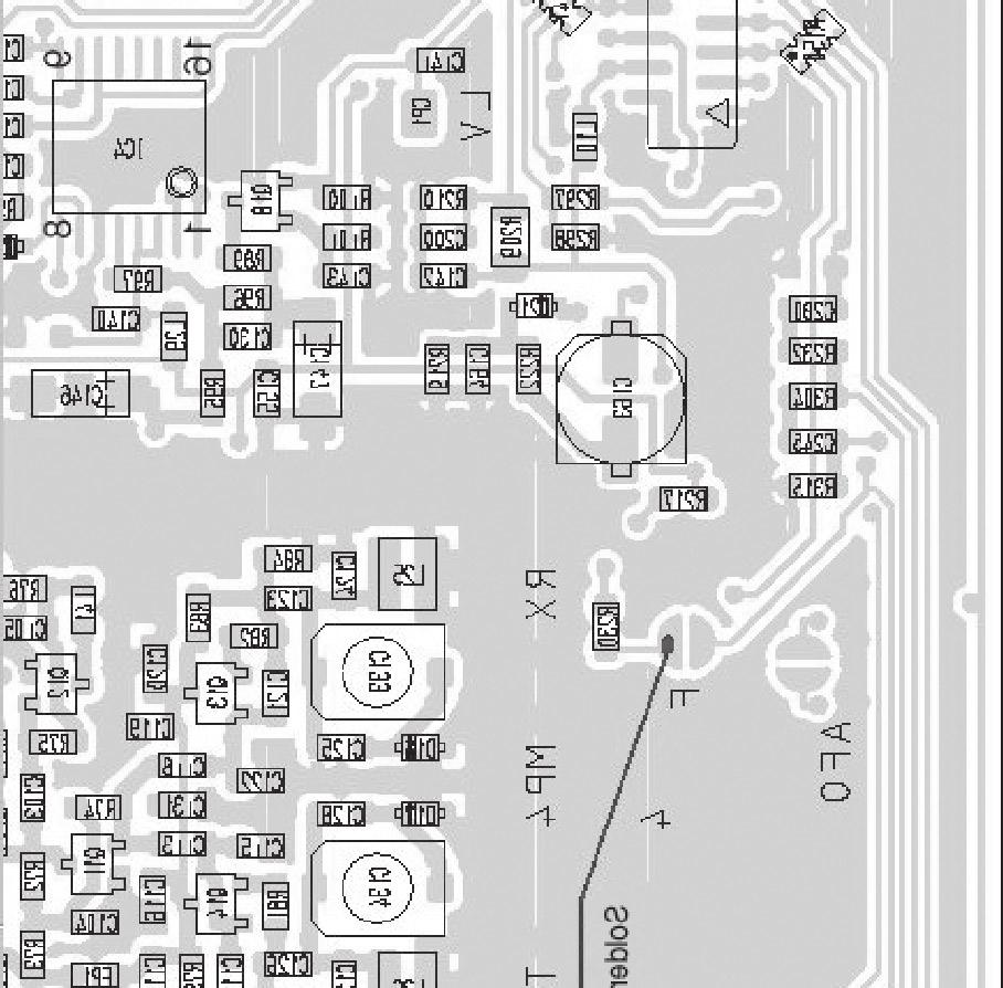
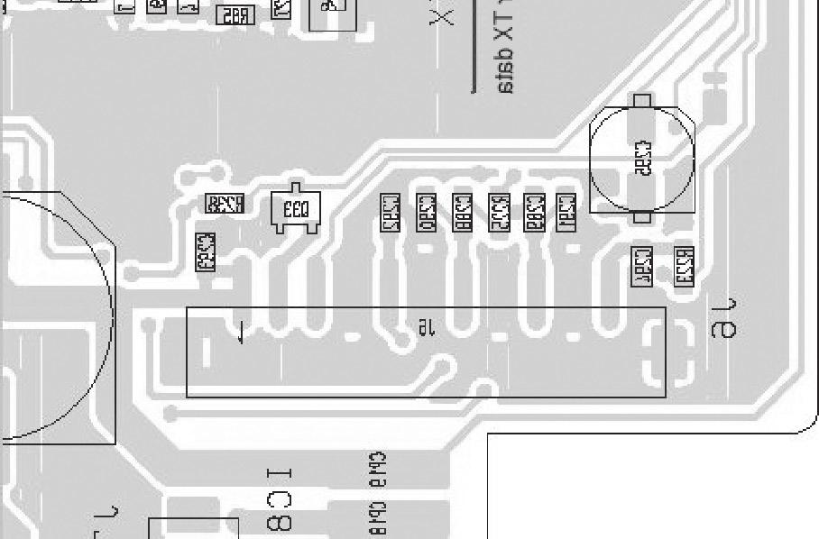
7 Repeater Controller Programming Mobile Radios ➀ Transmitter: Go to LMR>Memory CH>Free, Program the TX and RX to the transmit frequency Set the CTCSS/CDCSS Tone Set RF Power to High Go to LMR>Common>Expert, Set EPTT/ FTSW to EPTT (to allow ExtPTT) * Inside the TX radio, Short jumper D and solder TXData to F ➁ Receiver: Go to LMR>Memory CH>Free, Program the RX frequency Set the CTCSS/CDCSS Tone Enable TX inhibit Set RF Power to LOW2 Go to LMR>Common>Expert, set RX EXO to ON (to enable Signal HORN, CSQ, and PL/DPL) CABLE CONNECTORS X1 X2 X3 X4 X5 Accessory Connector TX Accessory Connector RX FAN J6 Optional Connector RX J6 Optional Connector TX HANG ON TIME CONFIGURATION JP7 JP6 JP5 JP4 T sec ** 1 = ON; 0 = OFF PANEL DESCRIPTION 1 JUMPER SETTINGS JP2 Repeater Disable JP3 Transmit On JP4 Hang On Time JP5 Hang On Time JP6 Hang On Time JP7 Hang On Time JP8 Audio On 4

8 5
9 6
10 PANEL DESCRIPTION 1 Accessory connector DB25 Pin Outs Configuration Pin No. Pin Name Description Specification 6 Vcc TX +15V DC Supply for External Controller, TX Maximum 1 A Unit 7 GND TX DC Ground, TX Unit 8 Busy TX Output Terminal for Busy Signal, TX Unit Open 9 AFO TX Audio Output, TX Unit 10 DISC TX Discriminator Output, TX Unit 11 TXA TX Transmit Audio, TX Unit 12 PTT TX External PTT, TX Unit 13 TXD TX Transmit Data Input, TX Unit 18 Vcc RX +15V DC Supply for External Controller, RX Unit 19 GND RX DC Ground, RX Unit 20 Busy RX Output Terminal for Busy Signal, RX Unit 21 AFO RX Audio Output, RX Unit 22 DISC RX Discriminator Output, RX Unit 23 TXA RX Transmit Audio, RX Unit Open Collector+OFF, 0V=ON 24 PTT RX External PTT, RX Unit 25 TXD RX Transmit Data Input, RX Unit 7

11 2 INSTALLATION AND CONNECTIONS Unpacking After unpacking, immediately report any damage to the delivering carrier or dealer. Keep the shipping cartons. For a description and a diagram of accessory equipment included with the CY-F121S/221S series, see ʻSupplied accessoriesʼ of this manual. Selecting a location Select a location for the repeater that allows adequate air circulation, free from extreme heat, cold, or vibrations, and away from TV sets, TV antenna elements, radios and other electromagnetic sources. Antenna connection For radio communications, the antenna is of critical importance, along with output power and sensitivity. Select antenna(s), such as a wellmatched 50 Ω antenna, and feedline. 1.5:1 or better of Voltage Standing Wave Ratio (VSWR) is recommended for desired band. Of course, the transmission line should be a coaxial cable. CAUTION: Protect repeater from lightning by using a lightning arrestor. NOTE: There are many publications covering proper antennas and their installation. Check with your local dealer for more information and recommendations. Duplexer A duplexer is separately required when only one antenna is used for both transmitting and receiving. Select a duplexer according to the transmitting and receiving frequencies. Ask your Dealer for details. Grounding To prevent electrical shock, television interference (TVI), broadcast interference (BCI) and other problems, ground the transceiver through the [GND] terminal on the rear panel. For best results, connect a heavy gauge wire or strap to a long earth-sunk copper rod. Make the distance between the [GND] terminal and ground as short as possible. WARNING: NEVER connect the [GND] terminal to a gas or electric pipe, since the connection could cause an explosion or electric shock. ➀ ➁ ➂ ➃ TYPE-N CONNECTOR INSTALLATION EXAMPLE Slide the nut, fl at washer, rubber gasket and clamp over the coaxial cable, then cut the end of the cable evenly. Strip the cable and fold the braid back over the clamp. Soft solder the center conductor. Install the center conductor pin and solder it. Carefully slide the plug body into place aligning the center conductor pin on the cable. Tighten the nut onto the plug body. 30 mm 9 8 in 10 mm 3 8 in 1 2 mm 1 16 in 8
![Required Connections INSTALLATION AND CONNECTIONS 2 [DC POWER INPUT TERMINAL] Make sure the back up battery is correctly connected. Use a cable with following current capacity.](/docs-images/96/128039632/images/12-4.jpg "Solder or clamp the cable plug when connecting the power cable to the backup battery to prevent voltage drops.")
12 Required Connections INSTALLATION AND CONNECTIONS 2 [DC POWER INPUT TERMINAL] Make sure the back up battery is correctly connected. Use a cable with following current capacity. Solder or clamp the cable plug when connecting the power cable to the backup battery to prevent voltage drops. Power cable current capacity: 25 A or more [T TX(TX RX) ANT] [RX ANT] GROUND TX RX antenna required for installing an internal duplexer. 9
13 Power Make sure the [POWER] switch is turned OFF when connecting an AC power cable or a backup battery (emergency power supply). The CY-F121S/221S series can operate with an AC or DC power supply. If AC power is interrupted when operating the repeater with an AC power supply, power is automatically provided to the [BATTERY] terminals. NOTE: If turning the repeater OFF using the rear panel switch, wait a few seconds before turning it back ON. Otherwise, Logic circuits may not sense the transition and operate correctly. In AC operation INSTALLATION AND CONNECTIONS 2 In DC operation CAUTION: Voltages greater than 16 V DC will damage the repeater. Check the source voltage before connecting the power cable. DO NOT place the backup battery on or near the repeater. Lead-acid batteries should be placed at least 5 m (16.4 ft.) away from the repeater. Use a heavy duty cable to make the connection and be sure both the positive (red) and negative (black) terminals are correctly connected. When connecting to the battery, connect the DC power cable to the repeater fi rst, then the positive (red) terminal and negative (black) terminal to the battery. This is to prevent electric shock or circuit damage. Use the supplied AC power cable for connection to a domestic AC outlet. Extension cords should not be used unless absolutely necessary. Using improper extension cords could result in fi re risk. 10

14 3 OPTIONAL UNIT INSTALLATION Opening the repeaterʼs case Follow the case and cover opening procedures shown here when an optional unit is installed or adjust the internal units, etc. CAUTION: Disconnect the AC power cable and/or DC power cable from the repeater. Otherwise, there is danger of electric shock and/or equipment damage. ➀ Remove 7 screws from the top of the repeater and 4 screws from the sides, then lift up the top cover. ➁ Turn the repeater upside down. 11
15 4 OPERATION Turning power ON ➀ On rear panel, push [POWER] to turn power ON. Receiving and transmitting Receiving ➀ Push [POWER] to turn power ON. ➁ Rotate [VOLUME] to adjust the audio output level. ➂ Push [1; 2; 3; 4] to select the desired channel. When receiving a signal, BUSY indicator turns ON and audio is emitted from the speaker. Further adjustment of [VOLUME] to a comfortable listening level may be necessary at this point. Transmitting ➀ Take the microphone off hook. ➁ Wait for the channel to become clear. ➂ Push and hold [PTT] to transmit, then speak into the microphone at your normal voice level. ➃ Release [PTT] to receive. IMPORTANT: To maximize the readability of the transmitted signal: (1) Pause briefl y after pushing [PTT]. (2) Hold the microphone 1 to 2 inch (2.5 to 5 cm) from your mouth, then speak into the microphone at a normal voice level. 12

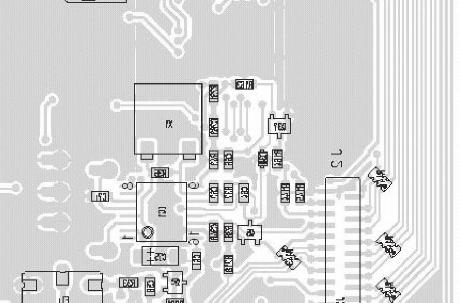
16 5 MAINTENANCE Fuse replacement If a fuse blows or the repeater stops functioning, try to fi nd the source of the problem, and replace the damaged fuse with a new, rated fuse. Replace the circuitry fuse as shown below. There are two fuses: The left fuse, as pictured, is for repeater TX The right fuse is for repeater RX WARNING: DISCONNECT the AC power cable and/or DC power cable from the repeater. Otherwise, there is danger of electric shock and/or equipment damage. 13
17 6 SPECIFICATIONS AND OPTIONS Specifications CY-F121S General Frequency coverage : MHz* Channel spacing : 12.5/25 khz (Narrow/Wide) Number of channels : Max 8 channels Antenna connector : SO-293 (50Ω) Power supply voltage : 13.2 V DC nominal [25W] (Negative ground) 13.6 V DC nominal [50W] Current drain (apporx.) : TX (25W) 7.0 A (50W) 13.0 A Max. Audio 1.2 A Stand-by 0.3 A Operating temp. range : -30 C to +60 C (-22 F to +140 F) Dimensions (Projections not included) [25W]: [50W]: 480 (W) x 133 (H) x 364 (D) mm; (W) x 5.24 (H) x (D) inches 480 (W) x 133 (H) x 364 (D) mm; (W) x 5.24 (H) x (D) inches Weight: 8.6 kg; 18 lb [25W] 8.6 kg; 18 lb [50W] RF output power: 25W/10W/2.5W [25W] (High/Low2/Low1) 50W/25W/5W [50W] Modulation system: Variable reactance freq. modulation Max. frequency deviation: ±2.5 khz [Narrow] ±5.0 khz [Wide] Frequency Error: ±5.0 ppm Spurious emission: 70 db typical Adjacent channel power: 60 db [Narrow] 70 db [Wide] Audio frequency response: +2 db to -8 db of 6 db/octave range from: 300 Hz to 2550 Hz [Narrow] 300 Hz to 3000 Hz [Wide] Audio harmonic distortion : 3% typical at 1 khz, 40% deviation FM Hum and noise: 40 db [Narrow] (typical, with CCIT fi lter) 46 db [Wide] Limiting character of: % of max deviation modulation Microphone connector: 8-pin modular (600Ω) Receiver Receive system: Double-conversion superheterodyne system Intermediate frequency: 1 st : MHz, 2 nd : 450 khz Sensitivity: 0.25 µv at 12 db SINAD Squelch sensitivity: 0.25 µv Adjacent channel: 65 db [Narrow] Selectivity (typical) 75 db [Wide] Spurious response: 75 db Intermodulation (typical): 74 db Hum and Noise (typical): 40 db [Narrow] 45 db [Wide] Audio output power: 4W typical at 10% distortion with a 4Ω load External SP connector: 2-conductor 3.5 (d) mm ( 1 / )/4Ω 8 CY-F221S General Frequency coverage: MHz* MHz* Channel spacing: 12.5/25 khz (Narrow/Wide) Number of channels: Max 8 channels Antenna connector: SO-293 (50Ω) Power supply voltage: 13.6 V DC nominal (negative ground) Current drain (apporx.): TX (25W) 7.0 A (45W) 13.0 A Max. Audio 1.2 A Stand-by 0.3 A Operating temp. range: -30 C to +60 C (-22 F to +140 F) Dimensions (Projections not included) [25W]: 480 (W) x 133 (H) x 364 (D) mm; (W) x 5.24 (H) x (D) inches [45W]: 480 (W) x 133 (H) x 364 (D) mm; (W) x 5.24 (H) x (D) inches Weight: 8.6 kg; 18 lb [25W] 8.6 kg; 18 lb [45W] Transmitter RF output power: 25W/10W/2.5W [25W] (High/Low2/Low1) 50W/25W/4.5W [45W] 14
18 Modulation system: Variable reactance freq. modulation Max. frequency deviation: ±2.5 khz [Narrow] ±5.0 khz [Wide] Frequency Error: ±2.5 ppm Spurious emission: 70 db typical Adjacent channel power: 60 db [Narrow] 70 db [Wide] Audio frequency response: +2 db to -8 db of 6 db/octave range from: 300 Hz to 2550 Hz [Narrow] 300 Hz to 3000 Hz [Wide] Audio harmonic distortion: 3% typical at 1 khz, 40% deviation FM Hum and noise: 40 db [Narrow] (typical, with CCIT fi lter) 46 db [Wide] Limiting character of: % of max deviation modulation Microphone connector: 8-pin modular (600Ω) Options HM-100 HAND MICROPHONE HM-100TN DTMF MICROPHONE Hand microphone with a DTMF keypad SM-25 DESKTOP MICROPHONE IAS VHF DUP KIT VHF duplexer kit with RF jumpers IAS UHF DUP KIT UHF duplexer kit with RF jumpers Receiver Receive system: Double-conversion superheterodyne system Intermediate frequency: 1 st : MHz, 2 nd : 450 khz Sensitivity: 0.25 µv at 12 db SINAD Squelch sensitivity: 0.25 µv Adjacent channe: 65 db [Narrow] Selectivity (typical) 75 db [Wide] Spurious response: 75 db Intermodulation (typical): 74 db Hum and Noise (typical): 40 db [Narrow] 45 db [Wide] Audio output power: 4W typical at 10% distortion with a 4Ω load External SP connector: 2-conductor 3.5 (d) mm ( 1 / )/4Ω 8 15
19
20 MEMO
21 Count on us! 7008
INSTRUCTION MANUAL. VHF dpmr REPEATER. ifr5000. UHF dpmr REPEATER. ifr6000
 INSTRUCTION MANUAL VHF dpmr REPEATER ifr5000 UHF dpmr REPEATER ifr6000 FORWARD Thank you for purchasing this Icom repeater. The IC- FR5000/IC-FR6000 vhf/uhf dpmr repeaters is designed and built with Icom
INSTRUCTION MANUAL VHF FM REPEATER. ifr5000 UHF FM REPEATER. ifr6000
 INSTRUCTION MANUAL VHF FM REPEATER ifr5000 UHF FM REPEATER ifr000 IMPORTANT EXPLICIT DEFINITIONS READ THIS INSTRUCTION MANUAL CAREFULLY before attempting to operate the repeater. SAVE THIS INSTRUCTION
INSTRUCTION MANUAL VHF TRANSCEIVER. if110s UHF TRANSCEIVER. if210s
 INSTRUCTION MANUAL VHF TRANSCEIVER if110s UHF TRANSCEIVER if210s IMPORTANT READ ALL INSTRUCTIONS carefully and completely before using the transceiver. SAVE THIS INSTRUCTION MANUAL This instruction manual
ic-f1020 ic-f2020 INSTRUCTION MANUAL VHF LAND MOBILE RADIO UHF LAND MOBILE RADIO
 INSTRUCTION MANUAL VHF LAND MOBILE RADIO ic-f1020 UHF LAND MOBILE RADIO ic-f2020 This device complies with Part 15 of the FCC Rules. Operation is subject to the condition that this device does not cause
INSTALLATION AND CONNECTIONS
 INSTALLATION AND CONNECTIONS 3 Unpacking After unpacking, immediately report any damage to the delivering carrier or dealer. Keep the shipping cartons. For a description and a diagram of accessory equipment
INSTALLATION AND CONNECTIONS Section 2
 STLLTION ND CONNECTIONS Section Unpacking - ntenna jumper cable connection - Selecting a location - Rack mounting handle attachment - Grounding -3 ntenna connection -3 CF (Compact Flash) memory card -3
QUICK REFERENCE GUIDE
 QUICK REFERENCE GUIDE Installation 1. Install a ground system for DC noise suppression and RFI suppression 2. Install your DC power supply 3. Install lightning protection. This will help protect more than
INSTRUCTION MANUAL VHF FM REPEATER. ifr5100 UHF FM REPEATER. ifr6100
 INSTRUCTION MANUAL VHF FM REPEATER ifr5100 UHF FM REPEATER ifr6100 IMPORTANT EXPLICIT DEFINITIONS READ THIS INSTRUCTION MANUAL CAREFULLY before attempting to operate the repeater. SAVE THIS INSTRUCTION
INSTRUCTION MANUAL VHF TRANSCEIVER. if111 if121 UHF TRANSCEIVER. if211 if221
 INSTRUCTION MANUAL VHF TRANSCEIVER if111 if121 UHF TRANSCEIVER if211 if221 IMPORTANT READ ALL INSTRUCTIONS carefully and completely before using the transceiver. SAVE THIS INSTRUCTION MANUAL This instruction
INSTRUCTION MANUAL VHF TRANSCEIVER. if111 if121 UHF TRANSCEIVER. if211 if221
 INSTRUCTION MANUAL VHF TRANSCEIVER if111 if121 UHF TRANSCEIVER if211 if221 IMPORTANT READ ALL INSTRUCTIONS carefully and completely before using the transceiver. SAVE THIS INSTRUCTION MANUAL This instruction
i2820h (USA) ie2820(europe)
 ie2820(europe)") January 2007 DUAL BAND TRANSCEIVERS i2820h (USA) ie2820(europe) The above photo shows the IC-2820H. The IC-E2820 differs slightly from this photo. Icom proudly announces the debut of the new dual band
January 2007 DUAL BAND TRANSCEIVERS i2820h (USA) ie2820(europe) The above photo shows the IC-2820H. The IC-E2820 differs slightly from this photo. Icom proudly announces the debut of the new dual band
i410pro ADVANCED MANUAL UHF CB TRANSCEIVER INTRODUCTION 1 ACCESSORIES AND INSTALLATION 2 BASIC OPERATION 3 SET MODE 4 REPEATER OPERATION 5 SCAN
 ADVANCED MANUAL INTRODUCTION 1 ACCESSORIES AND INSTALLATION 2 BASIC OPERATION 3 SET MODE UHF CB TRANSCEIVER i410pro 4 REPEATER OPERATION 5 SCAN 6 TONE SQUELCH AND POCKET BEEP 7 SELCALL (Selective Calling)
INSTRUCTION MANUAL VHF FM REPEATER. ifr3100 UHF FM REPEATER. ifr4100
 INSTRUCTION MANUAL VHF FM REPEATER ifr3100 UHF FM REPEATER ifr4100 IMPORTANT EXPLICIT DEFINITIONS READ THIS INSTRUCTION MANUAL CAREFULLY before attempting to operate the repeater. SAVE THIS INSTRUCTION
RMV25 / RMV50 RMU25 / RMU45
 RMV25 / RMV50 RMU25 / RMU45 Owner's Manual TABLE OF CONTENTS INTRODUCTION... 3 FCC Requirements... 3 SAFETY WARNING INFORMATION... 3 CONTROLS and INDICATORS... 5 FRONT PANEL... 5 LCD Icons and Indicators...
The amazing evolution of the 706 series
 The amazing evolution of the 706 series The IC-706MKIIG carries on the 706 series tradition of base station performance and features in a mobile reg-sized package. Building on this legacy, frequency coverage
INSTRUCTION MANUAL VHF TRANSCEIVER. if110 UHF TRANSCEIVER. if210
 INSTRUCTION MANUAL VHF TRANSCEIVER if110 UHF TRANSCEIVER if210 IMPORTANT READ ALL INSTRUCTIONS carefully and completely before using the transceiver. SAVE THIS INSTRUCTION MANUAL This instruction manual
INSTRUCTION MANUAL VHF AIR BAND TRANSCEIVER. ia110euro
 INSTRUCTION MANUAL VHF AIR BAND TRANSCEIVER ia110euro FOREWORD CAUTIONS READ ALL INSTRUCTIONS carefully and completely before using the transceiver. SAVE THIS INSTRUCTION MANUAL This instruction manual
INSTRUCTION MANUAL VHF/UHF ALL MODE TRANSCEIVER. i910h
 INSTRUCTION MANUAL VHF/UHF ALL MODE TRANSCEIVER i910h IMPORTANT EXPLICIT DEFINITIONS READ THIS INSTRUCTION MANUAL CAREFULLY before attempting to operate the transceiver. SAVE THIS INSTRUCTION MANUAL. This
INSTRUCTION MANUAL VHF TRANSCEIVER. if510 UHF TRANSCEIVER. if610
 INSTRUCTION MANUAL VHF TRANSCEIVER if510 UHF TRANSCEIVER if610 IMPORTANT READ ALL INSTRUCTIONS carefully and completely before using the transceiver. SAVE THIS INSTRUCTION MANUAL This instruction manual
ia110 INSTRUCTION MANUAL VHF AIR BAND TRANSCEIVER
 INSTRUCTION MANUAL VHF AIR BAND TRANSCEIVER ia110 This device complies with Part 15 of the FCC Rules. Operation is subject to the condition that this device does not cause harmful interference. FOREWORD
INSTRUCTION MANUAL VHF FM TRANSCEIVER TK-7102H UHF FM TRANSCEIVER TK-8102H KENWOOD CORPORATION B (M)
") INSTRUCTION MANUAL VHF FM TRANSCEIVER TK-7102H UHF FM TRANSCEIVER TK-8102H KENWOOD CORPORATION B62-1596-00 (M) 09 08 07 06 05 04 03 02 01 00 THANK YOU! We are grateful you chose KENWOOD for your personal
INSTRUCTION MANUAL VHF FM TRANSCEIVER TK-7102H UHF FM TRANSCEIVER TK-8102H KENWOOD CORPORATION B62-1596-00 (M) 09 08 07 06 05 04 03 02 01 00 THANK YOU! We are grateful you chose KENWOOD for your personal
INSTRUCTION MANUAL. VHF FM REPEATER ifr3100. UHF FM REPEATER ifr4100
 INSTRUCTION MANUAL VHF FM REPEATER ifr3 UHF FM REPEATER ifr4 IMPORTANT READ THIS INSTRUCTION MANUAL CAREFULLY before attempting to operate the repeater. SAVE THIS INSTRUCTION MANUAL This manual contains
i78 INSTRUCTION MANUAL HF TRANSCEIVER
 INSTRUCTION MANUAL HF TRANSCEIVER i78 This device complies with Part 15 of the FCC rules. Operation is subject to the following two conditions: (1) This device may not cause harmful interference, and (2)
TWS 16 HT UHF wireless system. user manual
 TWS 16 HT UHF wireless system user manual Musikhaus Thomann e.k. Treppendorf 30 96138 Burgebrach Germany Telephone: +49 (0) 9546 9223-66 E-mail: info@thomann.de Internet: www.thomann.de 30.04.2012 Table
Maintenance Manual. MTD SERIES 900 MHz, 10-WATT, DATA ONLY MOBILE RADIO. Mobile Communications LBI TABLE OF CONTENTS
 Mobile Communications MTD SERIES 900 MHz, 10-WATT, DATA ONLY MOBILE RADIO TABLE OF CONTENTS RF BOARD............................... LBI-38545 AUDIO BOARD............................ LBI-38546 LOGIC BOARD............................
SERVICE MANUAL ADDENDUM
 Mar. 2010 SERVICE MANUAL ADDENDUM CONTENTS PARTS LIST................................ 1 BOARD LAYOUTS........................... 5 VOLTAGE DIAGRAM......................... 7 Feb. 2010 SERVICE MANUAL ADDENDUM
OPERATING GUIDE VHF DIGITAL TRANSCEIVERS. if1000d. series UHF DIGITAL TRANSCEIVERS. if2000d series. The photo shows the VHF transceiver.
 OPERATING GUIDE VHF DIGITAL TRANSCEIVERS if1000d UHF DIGITAL TRANSCEIVERS series if2000d series The photo shows the VHF transceiver. TABLE OF CONTENTS 1. PANEL DESCRIPTION Front, top and side panels 1-2
INSTRUCTION MANUAL VHF FM REPEATER. ifr5100 UHF FM REPEATER. ifr6100
 INSTRUCTION MANUAL VHF FM REPEATER ifr500 UHF FM REPEATER ifr00 IMPORTANT EXPLICIT DEFINITIONS READ THIS INSTRUCTION MANUAL CAREFULLY before attempting to operate the repeater. SAVE THIS INSTRUCTION MANUAL
Technical Equipment Specification
 STATE OF CALIFORNIA Office of the State Chief Information Officer Public Safety Communications Division Technical Equipment Specification Equipment Type: Transmitter/Receiver Mobile Relay/Base/Control
ia110 INSTRUCTION MANUAL VHF AIR BAND TRANSCEIVER
 INSTRUCTION MANUAL VHF AIR BAND TRANSCEIVER ia110 This device complies with Part 15 of the FCC Rules. Operation is subject to the condition that this device does not cause harmful interference. FOREWORD
INSTRUCTION MANUAL VHF MOBILE TRANSCEIVER. if5061 if5063 UHF MOBILE TRANSCEIVER. if6061 if6063
 INSTRUCTION MANUAL VHF MOBILE TRANSCEIVER if5061 if5063 UHF MOBILE TRANSCEIVER if6061 if6063 i IMPORTANT READ ALL INSTRUCTIONS carefully and completely before using the transceiver. SAVE THIS INSTRUCTION
MZ2 HEADPHONE AMPLIFIER, PREAMP, & STEREO AMPLIFIER USER GUIDE
 MZ2 HEADPHONE AMPLIFIER, PREAMP, & STEREO AMPLIFIER USER GUIDE Linear Tube Audio Takoma Park, MD, USA WARNING: For safety, the cover of this amplifier should be secured at all times. DC voltages as high
Rack Mount Repeater VXR-9000E. Operating Manual. Vertex Standard LMR, Inc.
 Rack Mount Repeater VXR-9000E Operating Manual Vertex Standard LMR, Inc. Introduction The VXR-9000E is commercial-grade 25-watt FM repeater designed to provide reliable two-way full-duplex communications
INSTRUCTION MANUAL. VHF dpmr REPEATER. ifr5100. UHF dpmr REPEATER. ifr6100
 INSTRUCTION MANUAL VHF dpmr REPEATER ifr500 UHF dpmr REPEATER ifr00 FORWARD Thank you for purchasing this Icom repeater. The IC-FR500/IC-FR00 vhf/uhf dpmr repeaters is designed and built with Icom s state
INSTRUCTION MANUAL VHF MOBILE TRANSCEIVERS. if5120d. Series UHF MOBILE TRANSCEIVERS. if6120d. Series
 INSTRUCTION MANUAL VHF MOBILE TRANSCEIVERS if50d Series UHF MOBILE TRANSCEIVERS if60d Series i IMPORTANT READ ALL INSTRUCTIONS carefully and completely before using the transceiver. SAVE THIS INSTRUCTION
INSTRUCTION MANUAL UHF SRBR. if4sr
 INSTRUCTION MANUAL UHF SRBR if4sr FOREWORD CAUTIONS i READ ALL INSTRUCTIONS carefully and completely before using the transceiver. SAVE THIS INSTRUCTION MANUAL This instruction manual contains important
Model 1791 VHF Radio User's Manual
 Model 79 VHF Radio User's Manual ALL WEATHER INC 65 NATIONAL DRIVE SACRAMENTO, CA 95834 WWW.ALWEATHERINC.COM 79 VHF RADIO USER'S MANUAL CONTENTS INTRODUCTION... Description... Transmitter Module... Power
INSTRUCTION MANUAL UHF TRANSCEIVER. i400pro
 INSTRUCTION MANUAL UHF TRANSCEIVER i400pro i IMPORTANT READ ALL INSTRUCTIONS carefully and completely before using the transceiver. SAVE THIS INSTRUCTION MANUAL This instruction manual contains important
MobileRadio. Owner'sManual
 EMH MobileRadio Owner'sManual TABLE OF CONTENTS Introduction... 1 Basic Operation... 2 Code Guard Operation... 3 EMH Radio Controls... 4 Button Functions... 4 Built-in Features... 7 Keypad Microphone Operation...
User Manual. Specifications...3. Control and Operation Microphone...8. Installation...9. Installation of Main Unit...9
 Contents Specifications...3 Control and Operation...4-7 Microphone...8 Installation...9 Installation of Main Unit...9 Antenna Installation...9 Operational test...9 Frequency Bands Table...10 Frequency
Instruction Manual. Model: TX-446. Tech Private Mobile Radio (PMR)446MHz
446MHz") Instruction Manual Tech Private Mobile Radio (PMR)446MHz Model: TX-446 TTI TECH CO., LTD. Eundo Bldg, 737-19, Banpo-1dong, Seocho-ku, Seoul, Korea, 137-041 http://www.ttikorea.co.kr TABLE OF CONTENTS 1.
Instruction Manual Tech Private Mobile Radio (PMR)446MHz Model: TX-446 TTI TECH CO., LTD. Eundo Bldg, 737-19, Banpo-1dong, Seocho-ku, Seoul, Korea, 137-041 http://www.ttikorea.co.kr TABLE OF CONTENTS 1.
TWS 16 BT UHF wireless system. user manual
 TWS 16 BT UHF wireless system user manual Musikhaus Thomann e.k. Treppendorf 30 96138 Burgebrach Germany Telephone: +49 (0) 9546 9223-0 email: info@thomann.de Internet: www.thomann.de 09.03.2012 Table
Installation... 3 Installing The Radio... 3 Ignition Noise Interference... 4 Antenna... 4 External Speaker... 4 Public Address...
 TABLE OF CONTENTS CHAPTER 1 Specifications.............................................. 2 PAGE BIG RIG SERIES S 1 MOD PW R 20 0 3 SW R 40 1 5 5 60 1.5 7 10 2 9 20 80 3 30 +20 40 50 +40 100% MAX db +60
Downloaded from
 Owner s Manual AM/FM 40 CHANNEL & TONE SQUELCH CITIZENS BAND TRANSCEIVER Downloaded from www.cbradio.nl Characteristics of C-Five 1. Improved audio sensitivity by adopting audio compressing and decompressing
RACK MOUNT REPEATER VXR Vertex Standard LMR, Inc. VXR-9000 FM REPEATER OPERATING MANUAL
 RACK MOUNT REPEATER VXR-9000 OPERATING MANUAL Vertex Standard LMR, Inc. INTRODUCTION The VXR-9000 is commercial-grade 50-watt FM repeater designed to provide reliable two-way full-duplex communications
INSTRUCTION MANUAL FM HANDHELD TRANSCEIVER
 INSTRUCTION MANUAL PT558 FM HANDHELD TRANSCEIVER NOTE INSTRUCTION MANUAL PT558 FM HANDHELD TRANSCEIVER We are very grateful for your purchasing brand twoway radios produced by Kirisun Electronics (Shenzhen)
TWS One Headset UHF wireless system. user manual
 TWS One Headset UHF wireless system user manual Musikhaus Thomann Thomann GmbH Hans-Thomann-Straße 1 96138 Burgebrach Germany Telephone: +49 (0) 9546 9223-0 E-mail: info@thomann.de Internet: www.thomann.de
TWS 16 PT UHF wireless system. user manual
 TWS 16 PT UHF wireless system user manual Musikhaus Thomann Thomann GmbH Hans-Thomann-Straße 1 96138 Burgebrach Germany Telephone: +49 (0) 9546 9223-0 E-mail: info@thomann.de Internet: www.thomann.de 17.11.2015,
Operating Guide SMH 1525DT SMU 4525KT Technology Drive West Melbourne, FL RELM Wireless Corporation. All Rights Reserved CC OG 23
 W I R E L E S S C O R P O R AT I O N Operating Guide 7100 Technology Drive West Melbourne, FL 32904 2000 RELM Wireless Corporation. All Rights Reserved CC OG 23 ULUD01083ZZ RELM WIRELESS CORP. 7100 Technology
CON NEX HP. OWNER'S MANUAL Full Channel AM/FM Amateur Mobile Transceiver TABLE OF CONTENTS TUNING THE ANTENNA FOR OPTIMUM S.W.R..
 TABLE OF CONTENTS PAGE SPECIFICATIONS... 2 INSTALLATION... 3 LOCATION... 3 CON NEX - 4300HP MOUNTING THE RADIO... 3 IGNITION NOISE INTERFERENCE... 4 ANTENNA... 4 TUNING THE ANTENNA FOR OPTIMUM S.W.R..
RD988 Super Version. Intelligent Super Repeater
 RD988 Super Version Intelligent Super Repeater DMR Simulcast and DMR Trunking upgradable IP Multi-site Connection Digital telephone Interconnection RDAC Remote Management Software RD988 Super Version Intelligent
VX-4100/4200SERIES. VHF/UHF Mobile Radios
 VX-4100/4200SERIES VHF/UHF Mobile Radios HIGH POWER OUTPUT (50W VHF/45W UHF) WIDE FREQUENCY SPAN 134-174 MHz (VX-4104/4204) 400-470 MHz / 450-520 MHz (VX-4107/4207) 501 CHANNELS/32 GROUPS (VX-4200 SERIES)
i4088a INSTRUCTION MANUAL FRS UHF FM TRANSCEIVER
 INSTRUCTION MANUAL FRS UHF FM TRANSCEIVER i4088a This device complies with Part 15 of the FCC rules. Operation is subject to the following two conditions: (1) This device may not cause harmful interference,
POWER AMPLIFIER. Owner s Manual Mode d emploi Bedienungsanleitung Manual de instrucciónes CLIP SIGNAL TEMP PROTECTION POWER
 POWER AMPLIFIER Owner s Manual Mode d emploi Bedienungsanleitung Manual de instrucciónes TEMP PROTECTION POWER A CLIP SIGNAL B ON OFF M Introduction Thank you for purchasing a Yamaha C450/320/160 series
DX 33HP. 10 Meter Amateur Mobile Transceiver OWNER S MANUAL. Download this Manual Free of Charge at
 DX 33HP SIG 1 3 TX PWR 5 7 9+30dB POWER HI NB/ANL MED LO HI LO BAND ECHO RX/TX VOL SQ MIC RF FM PA AM D/A E/B F/C ECHO TIME BAND 10 Meter Amateur Mobile Transceiver Download this Manual Free of Charge
AM/FM SYNTHESIZER TUNER
 OPERATING INSTRUCTIONS AM/FM SYNTHESIZER TUNER DT-930 UL TABLE OF CONTENTS 1. IMPORTANT SAFETY INSTRUCTIONS... 2 2. SAFETY PRECAUTIONS... 2 3. INFORMATION TO THE USER... 3 4. GENERAL DESCRIPTION... 3 5.
BASE TECH SERIES
 BASE TECH SERIES WWW.MIDLANDRADIO.COM BASE TECH SERIES HIGH PERFORMANCE CONTINUOUS DUTY MULTI-MODE BASE/REPEATER STATIONS HIGH PERFORMANCE CONTINUOUS DUTY MULTI-MODE BASE/REPEATER STATIONS INTELLIGENT
VXR-9000 RACK MOUNT REPEATER VXR-9000 FM REPEATER OPERATING MANUAL
 RACK MOUNT REPEATER VXR-9000 OPERATING MANUAL VERTEX STANDARD CO., LTD. 4-8-8 Nakameguro, Meguro-Ku, Tokyo 153-8644, Japan VERTEX STANDARD US Headquarters 10900 Walker Street, Cypress, CA 90630, U.S.A.
Cisco Aironet 13.5-dBi Yagi Mast Mount Antenna (AIR-ANT1949)
") Cisco Aironet 13.5-dBi Yagi Mast Mount Antenna (AIR-ANT1949) Overview This document describes the 13.5-dBi Yagi mast mount antenna and provides instructions for mounting it. The antenna operates in the
Cisco Aironet 13.5-dBi Yagi Mast Mount Antenna (AIR-ANT1949) Overview This document describes the 13.5-dBi Yagi mast mount antenna and provides instructions for mounting it. The antenna operates in the
S5-ADU. Front... 4 Rear... 4
 Trantec ANTENNA DISTRIBUTOR INSTRUCTION MANUAL S5-ADU Thank you for purchasing TRANTEC Antenna Distributor. Please carefully follow the instructions in this manual to ensure long, trouble-free use of your
Midland 248XL I NSTRUCTION GUI DE
 Midland 248XL I NSTRUCTION GUI DE INDEX Introduction...2 Function and location of the controls...3 Installation...7 Power supply...7 Installing an antenna...7 How to use your Midland 248XL...8 Frequency
USER MANUAL VIVALDI MZ550A. Distribution Mixer Amplifier
 USER MANUAL VIVALDI MZ550A Distribution Mixer Amplifier 1. Security Precautions Carefully READ the instruction in this manual before use. Be sure to OBSERVE the INSTRUCTION in this manual regard convention
FCC ID: AXI IC: 10239A Alignment
 Introduction The VX-261 is carefully aligned at the factory for the specified performance across the frequency range specified for each version. Realignment should therefore not be necessary except in
TWS One Vocal UHF wireless system. user manual
 TWS One Vocal UHF wireless system user manual Musikhaus Thomann Thomann GmbH Hans-Thomann-Straße 1 96138 Burgebrach Germany Telephone: +49 (0) 9546 9223-0 E-mail: info@thomann.de Internet: www.thomann.de
OPERATING GUIDE VHF TRANSCEIVER. Iç-G88
 OPERATING GUIDE VHF TRANSCEIVER Iç-G88 INTRODUCTION PREFACE We appreciate you choosing Icom for your communication needs. The MDC 1200 signaling system is built into your IC-G88 vhf transceiver. IMPORTANT
Commercial Analogue Series VX-450, VX-4600 and VXR-9000
 Commercial Analogue Series VX-450, VX-4600 and VXR-9000 Meets the following standards: AS/NZS4295, ISO9001 and ISO4001 Commercial Analogue Series VX-450, VX-4600 and VXR-9000 Durable on-the-job responsiveness
Walkie-Talkie. User Manual and Instruction. Getting Started
 Walkie-Talkie User Manual and Instruction Getting Started Installing the AA Batteries Your radio uses 3 AA Alkaline batteries. 1. With the back of the radio facing you, lift the battery latch up to release
CLASS D MONO AMPLIFIER GM-D8601 GM-D9601. Owner s Manual
 CLASS D MONO AMPLIFIER GM-D8601 GM-D9601 Owner s Manual Before you start BE SURE TO OBSERVE THE FOLLOWING GUIDELINES:! Do not turn up the volume so high that you can t hear what s around you.! Use caution
FS-7006PA FS-7012PA YA-7000 POWER AMPLIFIERS. AMPLIFIER AUTO SWITCHING MODULE (Optional) OPERATING INSTRUCTIONS
 OPERATING INSTRUCTIONS") OPERATING INSTRUCTIONS POWER AMPLIFIERS AMPLIFIER AUTO SWITCHING MODULE (Optional) FS-7006PA FS-7012PA YA-7000 Thank you for purchasing TOA's Power Amplifiers. Please carefully follow the instructions
OPERATING INSTRUCTIONS POWER AMPLIFIERS AMPLIFIER AUTO SWITCHING MODULE (Optional) FS-7006PA FS-7012PA YA-7000 Thank you for purchasing TOA's Power Amplifiers. Please carefully follow the instructions
INSTRUCTION MANUAL VHF FM TRANSCEIVER TK-2206 UHF FM TRANSCEIVER TK-3206 B (M,M3 )
") INSTRUCTION MANUAL VHF FM TRANSCEIVER TK-2206 UHF FM TRANSCEIVER TK-3206 B62-1763-00 (M,M3 ) 09 08 07 06 05 04 03 02 01 00 THANK YOU We are grateful you chose KENWOOD for your land mobile radio applications.
INSTRUCTION MANUAL VHF FM TRANSCEIVER TK-2206 UHF FM TRANSCEIVER TK-3206 B62-1763-00 (M,M3 ) 09 08 07 06 05 04 03 02 01 00 THANK YOU We are grateful you chose KENWOOD for your land mobile radio applications.
Users Manual. 200W HF/50MHz Band Auto Antenna Tuner. Model HC-200AT
 Users Manual 200W HF/50MHz Band Auto Antenna Tuner Model HC-200AT Caution 1. Never remove or open the tuner cover while transmitting. When there is RF in the circuits of the tuner, there will be high voltage
IP Series DUAL POWER AMPLIFIERS
 OPERATING INSTRUCTIONS IP Series DUAL POWER AMPLIFIERS IP-600D IP-450D IP-300D TABLE OF CONTENTS 1. SAFETY PRECAUTIONS... 2 2. GENERAL DESCRIPTION... 4 3. FEATURES... 4 4. HANDLING PRECAUTIONS... 4 5.
HR MHZ AM-FM AMATEUR RADIO HF TRANSCEIVER OWNER'S MANUAL. Content of the packaging
 HR-2800 28 MHZ AM-FM AMATEUR RADIO HF TRANSCEIVER OWNER'S MANUAL NOTICE! It is recommended to carefully read this owner s manual before using the product. This will also help to prevent illegal use of
User s Guide. SD-225 Series. 16 Channel UHF/VHF Data Radio.
 User s Guide SD-225 Series 16 Channel UHF/VHF Data Radio www.midlandradio.com FCC RF EXPOSURE COMPLIANCE REQUIREMENTS FOR OCCUPATIONAL USE ONLY The Federal Communications Commission (FCC), within its action
Using measurement methods described in Australian/New Zealand Standard AS/NZS 4770:2000
 Barrett 2050 HF transceiver Using measurement methods described in Australian/New Zealand Standard AS/NZS 4770:2000 General Specifications Equipment Standards Transmit frequency range Receive frequency
INSTRUCTION MANUAL HF AUTOMATIC TUNING ANTENNA AH-740. * The stand in the photo is not supplied with the tuning antenna.
 INSTRUCTION MANUAL HF AUTOMATIC TUNING ANTENNA AH-740 * The stand in the photo is not supplied with the tuning antenna. FOREWORD Thank you for purchasing the AH-740 hf au to m at i c tuning antenna. The
KWM Quartet Wireless microphone system
 KWM Quartet Wireless microphone system M A N U A L V E R S I O N 2. 0 2 4-1 1-1 4 Professional UHF wireless system with 4 x USB rechargeable handheld microphones Due to continuous product development,
IEM-75 UHF wireless system. user manual
 IEM-75 UHF wireless system user manual Musikhaus Thomann Thomann GmbH Hans-Thomann-Straße 1 96138 Burgebrach Germany Telephone: +49 (0) 9546 9223-0 E-mail: info@thomann.de Internet: www.thomann.de 02.09.2015,
IC-400pro - RADIOAFICION.COM
 PROCEDURES IC-400pro - 5- PREPARATION When you adjust the contents on pages 5-5 and 5-6, SOFT- WARE, the optional CS-400PRO ADJ SOFTWARE (Rev..0 or later), *OPC- JIG CABLE (modified OPC- CLONING CABLE;
14 CHANNEL FAMILY RADIO SYSTEM MODEL # FR142
 14 CHANNEL FAMILY RADIO SYSTEM MODEL # FR142 2001 Audiovox Electronics Corp., Hauppauge, NY 11788 Printed in China 128-6020 052FR142104 BEFORE OPERATING THIS PRODUCT PLEASE READ THESE INSTRUCTIONS COMPLETELY
TS-590SG HF/ 50MHz All-Mode TRANSCEIVER_
 New Product Release Information Oct 2014 TS-590SG HF/ 50MHz All-Mode TRANSCEIVER_ Kenwood introduces Updated to new G version new HF/50MHz All-Mode Transceiver Four years ago we launched our best-selling
if310 if320 UHF TRANSCEIVER if410 if420 INSTRUCTION MANUAL VHF TRANSCEIVER
 INSTRUCTION MANUAL VHF TRANSCEIVER if310 if320 UHF TRANSCEIVER if410 if420 This device complies with Part 15 of the FCC Rules. Operation is subject to the condition that this device does not cause harmful
GM339 & GM399 - Select V Mobile Radio Versatility & Sophistication on the Move
 GM339 & GM399 - Select V Mobile Radio Versatility & Sophistication on the Move Motorola GM339 & GM399 Select V Mobile Radios GM339 Versatility on the go GM399 Sophistication on the move In a rapidly changing
IC-F7000. Advanced selective call and ALE make HF communication easier than ever!
 Page 1 of 5 HF TRANSCEIVER IC-F7000 Advanced selective call and ALE make HF communication easier than ever! The IC-F7000 is an HF land mobile transceiver especially designed forlong distance communications.
SAGA PRO SERIES STEREO POWER AMPLIFIER OPERATION MANUAL
 SAGA PRO SERIES STEREO POWER AMPLIFIER OPERATION MANUAL INSTALLATION Use care in unpacking the amplifier, and be sure to save the carton and packing materials so that you can use them for moving, storing,
Introduction Pag. 1. Function and location of the controls Pag. 2. Installation Pag. 3. Power supply Pag. 3. Installing an antenna Pag.
 ALAN 121 INDEX Introduction Pag. 1 E N G L I S H Function and location of the controls Pag. 2 Installation Pag. 3 Power supply Pag. 3 Installing an antenna Pag. 4 How to operate with your transceiver Pag.
T6M Base Station User Guide
 T6M Base Station User Guide Handbook Part Number: 31-360T6MBS Handbook Title: Handbook Part Number: Issue Number: 31-360T6MBS one Date of Issue: September 2000 Published by: Park Air Electronics Northfields
Cross-Connect Interface
 Cross-Connect Interface User Manual Document #: 050-015-0036R01 November 2006 TASC Systems Inc. Langley, BC Canada Cross-Connect System User Manual Preface This document describes the installation, commissioning
Up to 99 channel operation and widespaced
 Up to 99 channel operation and widespaced separation Two piece radio with small control head Easy to read 2-digit LED display Program from 1-99 channels Priority scan MARATRAC Mobile Accessories HMN1015A
RD982i-S. Intelligent Super Repeater
 DMR Simulcast and DMR Trunking upgradable IP Multi-site Connection Digital telephone Interconnection RDAC Remote Management Software Intelligent Super Repeater RD982i-S RD982i-S Intelligent Super Repeater
mat-180h HF-SSB Automatic Antenna Tuner Instruction Manual Version V1.0
 INTRODUCTION mat-180h HF-SSB Automatic Antenna Tuner Instruction Manual Version V1.0 The mat-180h is an automatic tuner intended for use with modern Icom transceivers. It works with any Icom transceiver
EDACS WALL MOUNT STATION. Maintenance Manual. Mobile Communications LBI-31838A TABLE OF CONTENTS
 A Mobile Communications EDACS WALL MOUNT STATION TABLE OF CONTENTS SYSTEM BOARD & REGULATOR BOARD.......... LBI-31892 KEY/DISPLAY BOARD MAINTENANCE MANUAL.... LBI-31940 Maintenance Manual Printed in U.S.A.
Instruction Manual PMR-101TX. Private Mobile Radio. TTI Tech. 446MHz, 8 Channels
 PMR-101TX Instruction Manual Private Mobile Radio 446MHz, 8 Channels? 38 CTCSS Sub Tone? 8 Channels? VOX Mode? Scanning? Monitor? Key Pad Lock? Dual Watch? Auto Power Save Mode? Battery Status Indicator?
LBI-31564A. Mobile Communications. DELTA - SX MHz RADIO COMBINATIONS (NEGATIVE GROUND ONLY) Maintenance Manual
 Maintenance Manual") A Mobile Communications DELTA - SX 136-174 MHz RADIO COMBINATIONS (NEGATIVE GROUND ONLY) Maintenance Manual TABLE OF CONTENTS MILITARY AND SYSTEM SPECIFICATIONS................................. 2-3 COMBINATION
A Mobile Communications DELTA - SX 136-174 MHz RADIO COMBINATIONS (NEGATIVE GROUND ONLY) Maintenance Manual TABLE OF CONTENTS MILITARY AND SYSTEM SPECIFICATIONS................................. 2-3 COMBINATION
TMP40. User Manual.
 TMP40 User Manual www.audac.eu ADDITIONAL INFORMATION This manual is put together with much care, and is as complete as could be on the publication date. However, updates on the specifications, functionality
INSTRUCTION MANUAL UHF C.R.S.TRANSCEIVER. i41s
 INSTRUCTION MANUAL UHF C.R.S.TRANSCEIVER i41s IMPORTANT READ ALL INSTRUCTIONS carefully and completely before using the transceiver. SAVE THIS INSTRUCTION MANUAL This instruction manual contains important
INSTRUCTION MANUAL VHF MOBILE TRANSCEIVER. if5061/d if5063 UHF MOBILE TRANSCEIVER. if6061/d if6063
 INSTRUCTION MANUAL VHF MOBILE TRANSCEIVER if506/d if5063 UHF MOBILE TRANSCEIVER if606/d if6063 IMPORTANT EXPLICIT DEFENITIONS READ ALL INSTRUCTIONS carefully and completely before using the transceiver.
Content. Maintenance. Features ENGLISH. 1 transceiver 1 antenna 1 battery pack 1 belt clip 1 fast desktop charger User manual
 ENGLISH Content 1 transceiver 1 antenna 1 battery pack 1 belt clip 1 fast desktop charger User manual If any items are missing, contact your dealer. Maintenance Your Two Way Radio is an electronic product
VX-4000 SERIES. VHF/UHF Mobile Radios
 VX-4000 SERIES VHF/UHF Mobile Radios 250 CHANNEL CAPACITY POWER OUTPUT: 70 W (LOW BAND), 50 W (VHF), 40 W (UHF) MIL- STD 810 C/D/E 12.5 / 25 khz BANDWIDTH PROGRAMMABLE PER CHANNEL 2.5 khz STEP FOR VHF/UHF
Version 1.0 November 2007
 Version 1.0 November 2007 IC-FR3000/FR4000 Series Sales Handbook FOREWORD and DISCLAIMER Foreword This handbook is prepared to provide detailed information about the IC-FR3000/FR4000 series VHF and UHF