BARTINGTON INSTRUMENTS. How to use this Manual... 3 Symbols Glossary Introduction to the Mag Vector Measurements and Conventions...
|
|
|
- Robert Wilkins
- 5 years ago
- Views:
Transcription


1
2
3 Table of Contents How to use this Manual... 3 Symbols Glossary... 3 Introduction to the Mag Vector Measurements and Conventions... 4 Installing the Mag Siting the Magnetometer (Environment Recommendations)... 5 Cable Recommendations... 5 Pre-Installation Tests... 6 Mounting Recommendations... 7 Post Installation Testing... 7 Using the Mag Magnetic Hysteresis... 8 Environmental Precautions... 8 Troubleshooting... 9 Care and Maintenance Cleaning the Mag Calibration End of Life Disposal Page 1 of 10 ISSUE 4
4 Page 2 of 10 ISSUE 4
5 How to use this Manual This document describes the installation, operation and maintenance of Mag648 magnetic field sensors. Take the time to get well acquainted with your Mag648(s) by reading this manual. Knowing and understanding your sensors will ensure you experience the most reliable operation. When service or maintenance is required, contact the Bartington Instruments helpdesk. Technical specifications for this product can be found in the appropriate datasheets. Details can be found on the Bartington website. Visit the Bartington Instruments website regularly for more information about any changes to our product range, for software downloads, datasheets and for support details. You can access all the information you need about your specific sensor, including service information at Symbols Glossary The following symbols used within this manual call your attention to specific types of information: WARNING: Indicates a situation in which serious bodily injury or death could result if the warning is ignored. Caution: Indicates a situation in which bodily injury or damage to your instrument, or both, could result if the caution is ignored. Identifies items that must be disposed of safely to prevent unnecessary damage to the environment. Note: A note provides useful supporting information and sometimes suggests how to make better use of your purchase. Page 3 of 10 ISSUE 4
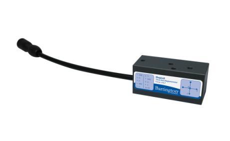
6 Introduction to the Mag648 The Mag648 is a magnetometer consisting of a cluster of three, feedback stabilised, fluxgate sensors arranged along X, Y and Z axes. Each axis provides a highly linear magnetic response with low hysteresis and low cross talk between axes. These characteristics, combined with the compact design and very low power consumption make this magnetometer ideally suited for perimeter surveillance with a multi-sensor network. Regulating the power supply internally ensures the Mag648 is suitable for battery powered operation, over both long and short cables. High stability circuitry ensures that a minimum of ten years service should be expected. Vector Measurements and Conventions Each magnetometer produces three independent analogue output voltages in response to the magnitude and direction of the orthogonal components of a magnetic field. A "right-hand" co-ordinate system is adopted. In this system the X, Y and Z axis correspond to the thumb, first and second finger respectively of the right hand. By convention, the magnetometer should be installed so that the X axis is arranged to point North, the Y axis to point East and the Z axis to point down. The centres of the three vector sensors are superimposed; each orientation is denoted on the magnetometer s label. The point of each vector arrow indicates the positive direction of each axis. Page 4 of 10 ISSUE 4
7 Installing the Mag648 Siting the Magnetometer (Environment Recommendations) The magnetometer should be sited several meters from any magnetic base rock to avoid compromising measurements Site the magnetometer several tens of meters from very large ferromagnetic object that could become magnetised and create fields exceeding the measuring range of the sensor Avoid siting the sensor near any ferromagnetic objects that may be subjected to the effects of magnetic hysteresis, which would affect the sensor in an unpredictable manner For these reasons, a magnetic evaluation of any proposed installation site should be conducted to establish that it is free from magnetic contaminants. It is recommended that such an evaluation be carried out using total field or resonance magnetometers. Cable Recommendations The standard magnetometer provides differential output lines for analogue signal transmission. The advantages of this differential arrangement are very high common-mode noise rejection and the suitability of readily available cable types. Each of the two anti-phase output lines has low output impedance at the signal source, damping the lines and preventing ringing. Cable inductance and capacitance considerations require the cable to be terminated with a differential amplifier having a circa 50kΩ input impedance. This arrangement will provide some damping to high frequencies but will attenuate the signals over the frequency range of the sensor. Due to these effects: The cable pair loop resistance should not exceed 0.1 ohms per metre The pair loop inductance should not exceed 0.5 micro-henry per metre The capacitance between should not exceed 52pF per metre The capacitance between conductors and shield should not exceed 120pF per metre To optimise operational life of underwater cables and avoid physical damage to the joint during handling: 1. Use a water-blocked cable. 2. Reduce the risk of stress on the soldering by ensuring there is adequate slack in the wire between the cable and the wire terminations. 3. Brace the slack with epoxy resin before moulding the cable to the connector. 4. Fit additional protection in the form of a plastic hose, or sleeve, around the cable(s) at the emergence point. Note: Cables are particularly prone to wear and damage at the point where they emerge at the surface of the ground, or sea. Page 5 of 10 ISSUE 4
8 Pre-Installation Tests Prior to the installation of the system, the magnetometer, cable and power supply must be fully tested to ensure correct function as follows: tests. Caution: Take care to avoid bending, or otherwise damaging the contacts whilst conducting the 1. Test the cables for continuity (using an electrical continuity tester or ohmmeter). a. Test the cables end to end at the connectors to ensure the correct pins have been allocated to the conductors and there are no open, or high resistance circuits. Note: Cable resistance will vary; refer to the appropriate datasheet for the expected values. b. Test the cables at the connectors to ensure there are no short circuits between the conductors. 2. Check the power supply output voltage using a voltmeter. Refer to the appropriate datasheet for the expected values. 3. Connect the magnetometer to the cable connector. 4. Connect the power supply to the other cable connector. 5. Switch on the power supply. 6. For each of the three (X, Y and Z) axes in turn: a. Connect a voltmeter to the axis sensor outputs, i.e. across +X and X. b. Whilst monitoring the voltmeter readings, align the magnetometer with the terrestrial field. c. Confirm the measured readings approach the local geomagnetic field value. Note: Geomagnetic field values can be provided by your local magnetic observatory. A margin of error due to local disturbance should be taken into account. Page 6 of 10 ISSUE 4
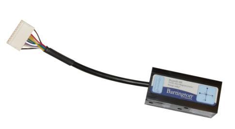
9 Mounting Recommendations Each magnetometer has a set of mounting holes to allow attachment to a stable base of fixture. Refer to the appropriate datasheet for further information as shown in the mechanical drawings. Caution: For the Mag648S only - Take care to avoid damage to the connector or magnetometer by correctly aligning the cable to the connector. When aligned correctly, hand tighten the connector. Refer to the appropriate datasheet for detailed information. Note: Other versions of the Mag648 have plug-in type connectors Post Installation Testing 1. Site the magnetometer, and install the power supply and cabling. 2. Switch on the power supply and wait until the magnetometer has stabilised. Refer to the appropriate datasheet for warm-up times. 3. Confirm no magnetic objects are moving in the vicinity. 4. Monitor the sensor outputs. 5. Confirm that the sum of the measured magnetic field vectors is similar to the expected local earth field. Note: The outputs from the sensor should remain stable to within the quoted noise limits. Refer to the appropriate datasheet for the expected values. Page 7 of 10 ISSUE 4
10 Using the Mag648 Magnetic Hysteresis The Mag648 is designed to have an extremely low magnetic hysteresis. However, Bartington Instruments recommends your magnetometer is not subjected to magnetic fields greater than their stated measuring range for extended periods as this could alter the DC offset. If this occurs, the offset will exhibit drift as it returns to its original offset specification. Caution: Subjecting the magnetometer to fields in excess of 2 x the nominal range may cause inaccuracy in future measurements. Degaussing the magnetometer can reverse such an effect. Environmental Precautions Refer to the datasheet for maximum environmental electrical and mechanical ratings. Caution: Exceeding the maximum environmental ratings may cause irreparable damage to your sensor. Page 8 of 10 ISSUE 4
11 Troubleshooting Your Mag648 is unlikely to suffer any defects in normal use: no internal components are serviceable. The most likely causes of failure, and their solutions, are detailed in the following table: Cause Power Supply Cables Power Input Magnetometer (with no integrated cable) Solution Check the power supply as detailed in Pre- Installation Tests Check the power. Check the cables as detailed in Pre-Installation Tests Test the cables. If no fault can be found in the power supply or cables, ensure the cable length is not too long, causing excessive voltage drop between the power supply and magnetometer. Refer to the specifications defined in the datasheet No physical damage to this type of Mag648 can be repaired. Replace with a new unit. For information about disposal of the damaged unit, refer to End of Life Disposal. Magnetometer (with integrated cable) Physical damage to the cable connector of this type of Mag648 can be repaired. Contact the Bartington Instruments helpdesk. Any other damage to the Mag648 is irreparable. Replace with a new unit. For information about disposal of the damaged unit, refer to End of Life Disposal. Page 9 of 10 ISSUE 4
12 Care and Maintenance Apart from the end connector of the Mag648-MX magnetometer (with integrated cable), no other repair or servicing is possible. For further details refer to the section on Troubleshooting. Cleaning the Mag648 Use water and mild soap to remove grime. Caution: Never use chemicals, such as solvents, when cleaning the Mag648. Caution: Take particular care when cleaning around electrical connections. Bent or damaged pins may cause the magnetometer to malfunction. Calibration Return the Mag648 to Bartington Instruments for calibration at the recommended intervals. Refer to the Calibration Certificate for further details. End of Life Disposal This symbol of the crossed-out wheelie bin indicates that the product (electrical and electronic equipment) should not be placed in municipal waste. Check local regulations for disposal of electronic products. For details of when to dispose of your Mag648 refer to the section on Troubleshooting. Page 10 of 10 ISSUE 4
13

14
Operation Manual for. Mag648 and Mag649 Low Power Three-Axis Magnetic Field Sensors
 Operation Manual for Mag648 and Mag649 Low Power Three-Axis Magnetic Field Sensors Table of Contents 1. About this Manual 3 1.1. Symbols Glossary 3 2. Safe Use 3 3. Introduction to the Mag648 & Mag649
Operation Manual for. Mag585 and Mag592 Low Radiation Three-Axis Magnetic Field Sensors
 Operation Manual for Mag585 and Mag592 Low Radiation Three-Axis Magnetic Field Sensors Table of Contents 1. How to use this manual 4 1.1. Symbols glossary 4 2. Safe use 4 3. Introduction to the Mag585
Operation Manual for. Mag690 Three-Axis Fluxgate Magnetometer.
 Operation Manual for Mag690 Three-Axis Fluxgate Magnetometer www.bartingtondefenceandspace.com www.bartingtondefenceandspace.com Table of Contents 1. How to Use this Manual 3 1.1. Symbols Glossary 3 2.
Operation Manual for. Mag658 Digital Three-Axis Magnetometer
 Operation Manual for Mag658 Digital Three-Axis Magnetometer Table of Contents 1. About this Manual 3 1.1. Symbols Glossary 3 2. Safe Use 3 3. Introduction to the Mag658 3 3.1. Vector Measurements and Conventions
Operation Manual for. Mag690 Three-Axis Fluxgate Magnetometer
 Operation Manual for Mag690 Three-Axis Fluxgate Magnetometer Table of Contents 1. About this Manual 4 1.1. Symbols Glossary 4 2. Safe Use 4 3. Introduction to the Mag690 4 3.1. Vector Measurements and
OM2225. Mag-03RC Three-axis Marine Magnetometer
 OM2225 Mag-03RC Three-axis Marine Magnetometer Table of Contents How to use this Manual... 3 Symbols Glossary... 3 Introduction to the Mag-03RC... 4 Vector Measurements and Conventions... 5 Output Voltage
Low Cost Three-Axis Fluxgate Sensor GFS-E. Measurement Range up to ±1000μT Output Voltage Calibration Error: 0.5% Noise 20pTrms/ Hz at 1Hz
 Handheld 3-Axis Gaussmeter Gaussmeter Fluxgate Low Cost Three-Axis Fluxgate GFS-E Measurement Range up to ±1000μT Output Voltage Calibration Error: 0.5% Noise 20pTrms/ Hz at 1Hz Description: Low Cost Three-Axis
User s Manual Current Probe. IM E 1st Edition. Yokogawa Electric Corporation
 User s Manual 701932 Current Probe Yokogawa Electric Corporation 1st Edition Foreword Revisions Thank you for purchasing the 701932 Current Probe. This user's manual contains useful information about the
For ultra-high precision measurement of current: DC, AC, pulsed..., with galvanic separation between primary and secondary. Applications.
 Current Transducer IT 205-S ULTRASTAB I PN = 200 A For ultra-high precision measurement of current: DC, AC, pulsed..., with galvanic separation between primary and secondary. Features Wide operating temperature
For the electronic measurement of current: DC, AC, pulsed..., with galvanic separation between the primary and the secondary circuit.
 Current Transducer IN 1000-S N = 1000 A For the electronic measurement of current: DC, AC, pulsed..., with galvanic separation between the primary and the secondary circuit. Features Closed loop (compensated)
Thank you again for choosing AstroAI, if you have any questions or concerns regarding your product, please contact us at
 ASTROAI USER MANUAL DT132A 4000 Count Auto-Ranging Multimeter Thank you for purchasing the AstroAI DT132A 4000 Count Auto-Ranging Multimeter. It is a 3 ¾ digit, 3999 counts, auto-ranging digital multimeter.
For ultra-high precision measurement of current: DC, AC, pulsed..., with galvanic separation between primary and secondary. Applications.
 Current Transducer IT 200-S ULTRASTAB I PM = 200 A For ultra-high precision measurement of current: DC, AC, pulsed..., with galvanic separation between primary and secondary. Features Closed loop (compensated)
For ultra-high precision measurement of current: DC, AC, pulsed..., with galvanic separation between primary and secondary. Applications.
 Current Transducer ITN 1000-S ULTRASTAB I PM = 1000 A For ultra-high precision measurement of current: DC, AC, pulsed..., with galvanic separation between primary and secondary. Features Closed loop (compensated)
Mounting method DIN rail mounting or screw mounting Screw mounting Mass [g] Material Case: Plastics PCB: FR-4
![Mounting method DIN rail mounting or screw mounting Screw mounting Mass [g] Material Case: Plastics PCB: FR-4](/thumbs/74/71038524.jpg "Mounting method DIN rail mounting or screw mounting Screw mounting Mass [g] Material Case: Plastics PCB: FR-4") PWM Controller Features Reduces system power consumption and fan noise For PWM fan speed control, a PWM control circuit needs to be newly designed and configured. By using this product, however, PWM control
PWM Controller Features Reduces system power consumption and fan noise For PWM fan speed control, a PWM control circuit needs to be newly designed and configured. By using this product, however, PWM control
ALM473 DUAL MONO \ STEREO AUDIO LEVEL MASTER OPERATION MANUAL IB
 ALM473 DUAL MONO \ STEREO AUDIO LEVEL MASTER OPERATION MANUAL IB6408-01 TABLE OF CONTENTS GENERAL DESCRIPTION 2 INSTALLATION 2,3,4 CONNECTION AND SETUP 4,5,6,7 FUNCTIONAL DESCRIPTION 8,9 MAINTENANCE 9
3B SCIENTIFIC PHYSICS
 3B SCIENTIFIC PHYSICS Digital Multimeter E 1018832 Instruction sheet 12/16 SD/UD 1 probe 1a Finger guards 2 Measurement socket 10 A for current measurement in 10-A (positive) 3 Measurement socket COM (negative)
For ultra-high precision measurement of current: DC, AC, pulsed..., with galvanic separation between primary and secondary. Applications.
 Current Transducer IT 605-S ULTRASTAB I PN = 600 A For ultra-high precision measurement of current: DC, AC, pulsed..., with galvanic separation between primary and secondary. Features Wide operating temperature
Model: PR-55. High Voltage Oscilloscope Probe 10 kv, 40 MHz USER MANUAL
 Model: PR-55 High Voltage Oscilloscope Probe 10 kv, 40 MHz USER MANUAL 1 2017 All rights reserved. B&K Precision products are covered by US and foreign patents, issued and pending. Information is this
AC/DC Resistance Standard DRR-112
 AC/DC Resistance Standard DRR-112 Operator's Manual DTM Instruments, LLC www.dtminstruments.com Version 2.0 November 2013 Introduction The AC/DC resistance standard DRR-112 is used to calibrate resistance
PalmGauss SC PGSC-5G. Instruction Manual
 PalmGauss SC PGSC-5G Instruction Manual PalmGauss SC PGSC 5G Instruction Manual Thank you very much for purchasing our products. Please, read this instruction manual in order to use our product in safety
User s Manual Current Probe IM E. 6th Edition
 User s Manual 701932 Current Probe 6th Edition Thank you for purchasing the 701932 Current Probe. This user s manual contains useful information about the functions and operating procedures of the 701932
NOTE: Fully read and understand this manual before using this Digital Multimeter.
 ASTROAI USER MANUAL AUTO RANGING DIGITAL CLAMP METER Thank you for purchasing the Auto Ranging Digital Clamp Meter from AstroAI. The AstroAI Auto Ranging Digital Clamp Meter is designed to be safely and
For the electronic measurement of current: DC, AC, pulsed..., with galvanic separation between the primary and the secondary circuit.
 Current Transducer IN 1000-S I P N = 1000 A For the electronic measurement of current: DC, AC, pulsed..., with galvanic separation between the primary and the secondary circuit. Features Closed loop (compensated)
Current Transducer CTSR 1-P = 1A
 Current Transducer CTSR 1-P I PRN = 1A For the electronic measurement of current: DC, AC, pulsed..., with galvanic isolation between the primary (high power) and the secondary circuit (electronic circuit).
High Temperature Fluxgate Probes
 INNOVATION IN MAGNETICS DS3629/3 High Temperature Fluxgate Probes www.bartington.com High Temperature Fluxgate Probes High Temperature Three-Axis Fluxgate Probes Designed to survive high levels of shock
PNI SEN-L Magneto-Inductive Sensor
 PNI SEN-L Magneto-Inductive Sensor General Description PNI Corporation s Magneto-Inductive (MI) sensors are based on patented technology that delivers breakthrough, cost-effective magnetic field sensing
Innovation in Magnetic Field Measuring Instruments. High Temperature Fluxgate Probes
 Innovation in Magnetic Field Measuring Instruments High Temperature Fluxgate Probes High Temperature Fluxgate Probes Bartington High Temperature Three-Axis Fluxgate Probes Designed to survive high levels
Device Interconnection
 Device Interconnection An important, if less than glamorous, aspect of audio signal handling is the connection of one device to another. Of course, a primary concern is the matching of signal levels and
PRECISION CURRENT TRANSDUCERS. DC Current Transducers CT-100 CT-150. User s Manual. All Rights Reserved CAEN ELS d.o.o. Rev. 1.
 < DC Current Transducers CT-100 CT-150 User s Manual PRECISION CURRENT TRANSDUCERS All Rights Reserved CAEN ELS d.o.o. Rev. 1.1 November 2014 CAEN ELS d.o.o. Kraška ulica, 2 6210 Sežana Slovenija Mail:
34134A AC/DC DMM Current Probe. User s Guide. Publication number April 2009
 User s Guide Publication number 34134-90001 April 2009 For Safety information, Warranties, Regulatory information, and publishing information, see the pages at the back of this book. Copyright Agilent
OPERATION & SERVICE MANUAL FOR FC 110 AC POWER SOURCE
 OPERATION & SERVICE MANUAL FOR FC 100 SERIES AC POWER SOURCE FC 110 AC POWER SOURCE VERSION 1.3, April 2001. copyright reserved. DWG No. FC00001 TABLE OF CONTENTS CHAPTER 1 INTRODUCTION... 1 1.1 GENERAL...
AT Advanced Wire Tracer. Users Manual
 AT-1000 Advanced Wire Tracer Users Manual AT-1000 Advanced Wire Tracer English Users Manual AT1000_Rev001 2008 Amprobe Test Tools. All rights reserved. Limited Warranty and Limitation of Liability Your
LCT100. Load Cell Tester User s Guide (v1711) Anyload Transducer Co. Ltd Website:
 Anyload Transducer Co. Ltd Website:") LCT100 Load Cell Tester User s Guide (v1711) Anyload Transducer Co. Ltd Website: www.anyload.com Email: info@anyload.com A. Basic Steps in Load Cell Testing using the LCT100: 1. Connect the load cell cable
LCT100 Load Cell Tester User s Guide (v1711) Anyload Transducer Co. Ltd Website: www.anyload.com Email: info@anyload.com A. Basic Steps in Load Cell Testing using the LCT100: 1. Connect the load cell cable
Magnetic Inductive Flow Sensor induq
 Operating manual (Translation) Operating manual... page 1-16 Magnetic Inductive Flow Sensor induq Series VMZ SIKA Ba_VMZ_en 10/2014. Please keep this operating manual for future reference. If the device
Electrical Multimeter
 113 Electrical Multimeter Instruction Sheet Safety Information A Warning statement identifies hazardous conditions and actions that could cause bodily harm or death. A Caution statement identifies conditions
DC Current Transducers CT-200 CT-300 CT-400 User s Manual All Rights Reserved CAEN ELS d.o.o. Rev. 1.0 November 2014
 < DC Current Transducers CT-200 CT-300 CT-400 User s Manual PRECISION CURRENT TRANSDUCERS All Rights Reserved CAEN ELS d.o.o. Rev. 1.0 November 2014 CAEN ELS d.o.o. Kraška ulica, 2 6210 Sežana Slovenija
For ultra-high precision measurement of current: DC, AC, pulsed..., with galvanic separation between primary and secondary. Applications.
 Current Transducer IT 700-SB ULTRASTAB I PM = 700 A For ultra-high precision measurement of current: DC, AC, pulsed..., with galvanic separation between primary and secondary. Features ± 10 V voltage output
Instruction Manual MSC710 MSC710-U MSC710-I
 Instruction Manual MSC710 MSC710-U MSC710-I Sensor controller for inductive displacement and gauging sensors series LVDT MICRO-EPSILON MESSTECHNIK GmbH & Co. KG Koenigbacher Strasse 15 94496 Ortenburg
INSTRUCTION MANUAL. IM7298, Revision A ( )
") INSTRUCTION MANUAL For Model 7298 Triaxial Microtron Variable Capacitance Accelerometer IM7298, Revision A (07-10-13) General Overview The Endevco Model 7298 Triaxial Microtron accelerometer is a rugged,
INSTRUCTION MANUAL For Model 7298 Triaxial Microtron Variable Capacitance Accelerometer IM7298, Revision A (07-10-13) General Overview The Endevco Model 7298 Triaxial Microtron accelerometer is a rugged,
Current Probe Fixture Instruction Manual
 Current Probe Fixture Instruction Manual 1 TABLE OF CONTENTS INTRODUCTION 3 GENERAL INFORMATION 4 TEST METHODS 5 SAFETY 7 FIGURES 8 FORMULAS 10 MAINTENANCE 11 WARRANTY 12 2 INTRODUCTION figure 1 Mechanical
High Performance Current Transducer IT 200-S ULTRASTAB = A. ε L
 High Performance Current Transducer IT 200-S ULTRASTAB For the electronic measurement of currents: DC, AC, pulsed..., with galvanic isolation between the primary circuit and the secondary circuit. I PM
AIM & THURLBY THANDAR INSTRUMENTS
 AIM & THURLBY THANDAR INSTRUMENTS I-prober 520 positional current probe Unique technology enabling current measurement in PCB tracks bandwidth of DC to 5MHz, dynamic range of 10mA to 20A pk-pk useable
OPERATOR S INSTRUCTION MANUAL
 2 OPERATOR S INSTRUCTION MANUAL CLAMP METER HOLD 20 A 200 A 2 A 600 600 LIGHT ON/OFF Digital Clamp Meter 2 20 200 A khz COM CAT.II MAX 600 CONTENTS 1. General instruction.....1 2. Description...1 2.1 Precautions
User s Manual. Miniature Passive Probe. IM EN 3rd Edition
 User s Manual Miniature Passive Probe IM 701946-01EN 3rd Edition Thank you for purchasing the miniature passive probe. This miniature passive probe is designed for user s safety and excellent easyto-use
Specify Gain and Phase Margins on All Your Loops
 Keywords Venable, frequency response analyzer, power supply, gain and phase margins, feedback loop, open-loop gain, output capacitance, stability margins, oscillator, power electronics circuits, voltmeter,
15B+/17B+/18B+ Calibration Manual. Digital Multimeter
 5B+/7B+/8B+ Digital Multimeter Calibration Manual April 206 206 Fluke Corporation. All rights reserved. Specifications are subject to change without notice. All product names are trademarks of their respective
APPLICATION NOTES FOR THROUGH-HOLE LEDs
 APPLICATION NOTES FOR THROUGH-HOLE s Storage conditions 1. Avoid continued exposure to the condensing moisture environment and keep the product away from rapid transitions in ambient temperature. 2. s
For ultra-high precision measurement of current: DC, AC, pulsed..., with galvanic separation between primary and secondary. Applications.
 Current Transducer IT 700-S ULTRASTAB I PM = 700 A For ultra-high precision measurement of current: DC, AC, pulsed..., with galvanic separation between primary and secondary. Features Closed loop (compensated)
OD4 PRODUCT NAME. user manual. user manual. Conditioning Module. Product Type
 OD4 Conditioning Module PRODUCT NAME Product Type user manual user manual 1.0 Index Section Title Page 1.0 Index...................... 2 2.0 Safety Information............ 3 3.0 Introduction.................
PNI SEN-L. Leaded Magneto-Inductive Sensor. Features. General Description. Applications. Ordering Information
 Updated August, 2006 PNI SEN-L Leaded Magneto-Inductive Sensor General Description PNI Corporation s Magneto-Inductive (MI) sensors are based on patented technology that delivers breakthrough, cost-effective
CONNECTING THE PROBE TO THE TEST INSTRUMENT
 2SHUDWLRQ 2SHUDWLRQ Caution The input circuits in the AP034 Active Differential Probe incorporate components that protect the probe from damage resulting from electrostatic discharge (ESD). Keep in mind
Meters and Test Equipment
 Installation Knowledge and Techniques Meters and Test Equipment OBJECTIVES Meters and Test Equipment DMM s and VOM s Describe the difference between a DMM and a VOM. Describe the methods for measuring
Series 70 Servo NXT - Modulating Controller Installation, Operation and Maintenance Manual
 THE HIGH PERFORMANCE COMPANY Series 70 Hold 1 sec. Hold 1 sec. FOR MORE INFORMATION ON THIS PRODUCT AND OTHER BRAY PRODUCTS PLEASE VISIT OUR WEBSITE www.bray.com Table of Contents 1. Definition of Terms.........................................2
IDEAL INDUSTRIES, INC. TECHNICAL MANUAL MODEL:
 IDEAL INDUSTRIES, INC. TECHNICAL MANUAL MODEL: 61-920 The Service Information provides the following information: Precautions and safety information Specifications Performance test procedure Calibration
TA MHz oscilloscope probe TA MHz oscilloscope probe
 TA375 100 MHz oscilloscope probe TA386 200 MHz oscilloscope probe User's Guide X1 X10 TA386 X1/X10 Max. 600 Vp Introduction This passive high-impedance oscilloscope probe is suitable for most oscilloscopes
RAZTEC LINK CURRENT SENSOR TECHNICAL INFORMATION
 RAZTEC LINK CURRENT SENSOR TECHNICAL INFORMATION DESCRIPTION The Raztec Link current sensor looks rather like a fuse or even a shunt but offers some very significant technical advantages over shunts when
Model 9305 Fast Preamplifier Operating and Service Manual
 Model 9305 Fast Preamplifier Operating and Service Manual This manual applies to instruments marked Rev 03" on rear panel. Printed in U.S.A. ORTEC Part No.605540 1202 Manual Revision B Advanced Measurement
Current Probes. User Manual
 Current Probes User Manual ETS-Lindgren Inc. reserves the right to make changes to any product described herein in order to improve function, design, or for any other reason. Nothing contained herein shall
INDEX PREFACE... 1 CAUTIONS... 2 OPERATION ON SITE(9) STANDARD INSTRUMENT... 3 OPTIONAL ACCESSORIES... 4 OPERATION OF TRANSMITTER(3)...
 STANDARD INSTRUMENT... 3 OPTIONAL ACCESSORIES... 4 OPERATION OF TRANSMITTER(3)...") INDEX PREFACE... 1 CAUTIONS... 2 STANDARD INSTRUMENT... 3 OPTIONAL ACCESSORIES... 4 OPERATION OF TRANSMITTER(1)... 5 (Transmitter Unit.) OPERATION OF TRANSMITTER(2)... 6 (Operation Panel, LCD Display of
INDEX PREFACE... 1 CAUTIONS... 2 STANDARD INSTRUMENT... 3 OPTIONAL ACCESSORIES... 4 OPERATION OF TRANSMITTER(1)... 5 (Transmitter Unit.) OPERATION OF TRANSMITTER(2)... 6 (Operation Panel, LCD Display of
For the electronic measurement of current: DC, AC, pulsed..., with galvanic separation between the primary circuit and the secondary circuit.
 Current Transducer CTSR 0.6-TP/SP2 I PRN = 600 ma For the electronic measurement of current: DC, AC, pulsed..., with galvanic separation between the primary circuit and the secondary circuit. Features
Single Supply, Rail to Rail Low Power FET-Input Op Amp AD820
 a FEATURES True Single Supply Operation Output Swings Rail-to-Rail Input Voltage Range Extends Below Ground Single Supply Capability from + V to + V Dual Supply Capability from. V to 8 V Excellent Load
Model Directional RF Wattmeter
 Model 81030 Directional RF Wattmeter Instruction Manual Table of Contents Paragraph Page Specifications and Leading Particulars.. 2 General Description 1. Purpose and Application...5 2. Description 5
Item ref: UK MTM01 DIGITAL MULTITESTER. User Manual
 Item ref: 600.100UK MTM01 DIGITAL MULTITESTER User Manual Please read this manual thoroughly and ensure all contents are fully understood before using the apparatus. Warning To avoid possible electric
An Improved Version of the Fluxgate Compass Module V. Petrucha
 An Improved Version of the Fluxgate Compass Module V. Petrucha Satellite based navigation systems (GPS) are widely used for ground, air and marine navigation. In the case of a malfunction or satellite
TA MHz ±30 V Differential Probe User s Manual. This probe complies with IEC , IEC CAT I, Pollution Degree 2.
 TA046 800 MHz ±30 V Differential Probe User s Manual This probe complies with IEC-1010.1, IEC-1010.2-031 CAT I, Pollution Degree 2. 1. Safety terms and symbols Terms appearing in this manual: WARNING Warning
MARTINDALE INSTRUCTIONS. E-ZeTest EZ2500 LOOP TESTER ELECTRIC. Trusted by professionals. Other products from Martindale:
 Other products from Martindale: 17th Edition Testers All-in-one s Calibration Equipment Continuity Testers Electrician s kits Full Calibration & Repair Service Fuse Finders Digital Clamp Meters Digital
User s Manual Current Probe. IM E 2nd Edition IM E
 User s Manual 700937 Current Probe 2nd Edition Introduction Thank you for purchasing the 700937 Current Probe. This Instruction Manual contains useful information about the instrument s functions and operating
Refer to manual. Failure to read message could result in personal injury or serious damage to the equipment or both.
 CERAVAC Transmitter CTR 100 N Short form manual 300544675_002_C0 Part numbers: 230 300V02 230 310V02 230 301V02 230 311V02 230 302V02 230 312V02 230 303V02 230 313V02 230 304V02 230 314V02 230 305V02 230
DIGIT & POINTER MULTIMETER
 CONTENTS DIGIT & POINTER MULTIMETER OPERATOR S MANUAL 1. SAFETY INFORMATION 1 1.1 PRELIMINARY 1 1.2 DURING USE 2 1.3 SYMBOLS 3 1.4 MAINTENANCE 3 2. DESCRIPTION 4 2.1 NAMES OF COMPONENTS 4 2.2 FUNCTION
User s Manual Current Probe IM E. 8th Edition
 User s Manual 701931 Current Probe 8th Edition Thank you for purchasing the Current Probe (Model 701931). This instruction manual contains useful information about the instrument s functions and operating
DUAL OUTPUT AC CURRENT/VOLTAGE TRANSDUCER
 OPERATOR S MANUAL DUAL OUTPUT AC CURRENT/VOLTAGE TRANSDUCER Masibus Automation & Instrumentation Pvt. Ltd. B/30, GIDC Electronics Estate, Sector-25, Gandhinagar-382044, Gujarat, India Web Site: www..com
INSTRUCTION MANUAL UTL260
 INSTRUCTION MANUAL UTL260 1-800-547-5740 Fax: (503) 643-6322 www.ueitest.com email: info@ueitest.com Introduction The UTL260 has all the features and measurement functions that appliance technicians need.
TRMS LEAKAGE CURRENT CLAMP-ON METER 565
 TRMS LEAKAGE CURRENT CLAMP-ON METER 565 E N G L I S H User Manual Statement of Compliance Chauvin Arnoux, Inc. d.b.a. AEMC Instruments certifies that this instrument has been calibrated using standards
Bulk Current Injection Probe Test Procedure
 Bulk Current Injection Probe Test Procedure 1 TABLE OF CONTENTS INTRODUCTION 3 GENERAL INFORMATION 4 TEST METHODS 6 SAFETY 8 FIGURES 9 FORMULAS 12 MAINTENANCE 13 WARRANTY 14 2 INTRODUCTION CURRENT PROBE
FMG90 Series Electromagnetic Flow Meter
 . FMG90 Series Electromagnetic Flow Meter - 2 - Series FMG90 Series FMG90 Table of contents page 0 About this operating manual... 4 1 Device description... 5 1.1 Delivery, unpacking and accessories...
User s Guide. RP7000 Series Active Probe. Dec RIGOL Technologies, Inc.
 User s Guide RP7000 Series Active Probe Dec. 2012 RIGOL Technologies, Inc. Guaranty and Declaration Copyright 2011 RIGOL Technologies, Inc. All Rights Reserved. Trademark Information RIGOL is a registered
TRIAXIAL FLUXGATE MAGNETOMETER OWNER'S MANUAL
 TRIAXIAL FLUXGATE MAGNETOMETER OWNER'S MANUAL PART NUMBER: FGM-301 WATSON INDUSTRIES, INC. 3041 MELBY ROAD EAU CLAIRE, WI 54703 Phone: (715) 839-0628 FAX: (715) 839-8248 email: support@watson-gyro.com
Operators Manual: Diamond Rock Saw Excavator Attachment Austramac Flashcut Series
 Operators Manual: Diamond Rock Saw Excavator Attachment Austramac Flashcut Series! WARNING! Inappropriate use of rock saw may cause serious injury or death. Operators must read this manual before use and
HAWK5000 Operators Manual
 HAWK5000 Operators Manual Keison Products P.O. Box 2124, Chelmsford CM1 3UP, England Tel: +44 (0) 1245 600560 Fax: +44 (0) 1245 600030 Email: sales@keison.co.uk www.keison.co.uk KANE INTERNATIONAL LIMITED
EEE 432 Measurement and Instrumentation
 EEE 432 Measurement and Instrumentation Lecture 6 Measurement noise and signal processing Prof. Dr. Murat Aşkar İzmir University of Economics Dept. of Electrical and Electronics Engineering Measurement
Amplified High Speed Photodetectors
 Amplified High Speed Photodetectors User Guide 3340 Parkland Ct. Traverse City, MI 49686 USA Page 1 of 6 Thank you for purchasing your Amplified High Speed Photodetector from EOT. This user guide will
EM420A/420B DIGITAL MULTIMETER OWNERS MANUAL Read this owners manual thoroughly before use
 http://www.all-sun.com EM420A/420B DIGITAL MULTIMETER OWNERS MANUAL V Read this owners manual thoroughly before use WARRANTY This instrument is warranted to be free from defects in material and workmanship
AIM & THURLBY THANDAR INSTRUMENTS
 AIM & THURLBY THANDAR INSTRUMENTS I-prober 520 positional current probe Unique technology enabling current measurement in PCB tracks bandwidth of DC to 5MHz, dynamic range of 10mA to 20A pk-pk useable
DC Current Transducers 4XCT-100-C-HP User s Manual All Rights Reserved CAEN ELS s.r.l. Rev. 1.0 February 2017
 PRECISION CURRENT TRANSDUCERS < DC Current Transducers 4XCT-100-C-HP User s Manual All Rights Reserved CAEN ELS s.r.l. Rev. 1.0 February 2017 CAEN ELS s.r.l. Via Vetraia, 11 55049 Viareggio (LU) Italy
User s Manual for Integrator Short Pulse ISP16 10JUN2016
 User s Manual for Integrator Short Pulse ISP16 10JUN2016 Specifications Exceeding any of the Maximum Ratings and/or failing to follow any of the Warnings and/or Operating Instructions may result in damage
Technical data. Your advantages
 Technical data Nominal torque: 50 Nm to 2.000 Nm, bidirectional Rotational speed: 10.000 rpm Accuracy: ±0,2 % Temperature range: -40 C to +85 C Protection class: IP50, IP65 Output signals: 0-10 V/4-20
Model 4800 O P E R AT I O N M A N U A L L O A D C E L L S U M M I N G T R A N S M I T T E R
 O P E R AT I O N M A N U A L Model 4800 L O A D C E L L S U M M I N G T R A N S M I T T E R CALEX Manufacturing Company, Inc. Concord, California 94520 Ph: 925/687-4411 800/542-3355 Fax: 925/687-3333 http://www.calex.com
VECTOR INVERTER -INSTRUCTION MANUAL- 16-BIT DIGITAL INPUT FR-V5AH
 VECTOR INVERTER -INSTRUCTION MANUAL- 16-BIT DIGITAL INPUT FR-V5AH Thank you for choosing the Mitsubishi vector inverter option unit. This instruction manual gives handling information and precautions for
I PM. Current Transducer ITZ 5000-SB FLEX ULTRASTAB = 5000 A
 urrent Transducer ITZ 5000-SB FLEX ULTRASTAB I PM = 5000 A For ultra-high precision measurement of current: D, A, pulsed..., with galvanic separation between primary and secondary. Separate magnetic head
Operators Manual (Manual A)
") CD201 SINGLE COLUMN CARD DISPENSER Operators Manual (Manual A) Contents A1 Scope... 1 A2 Specifications... 1 A3 Installation... 2 3.1 Unpacking and inspection... 2 3.2 Opening and closing the door... 2
CD201 SINGLE COLUMN CARD DISPENSER Operators Manual (Manual A) Contents A1 Scope... 1 A2 Specifications... 1 A3 Installation... 2 3.1 Unpacking and inspection... 2 3.2 Opening and closing the door... 2
ICA User Manual ICA. ICA Embedded Strain Gauge Analogue Amplifiers
 ICA User Manual ICA ICA Embedded Strain Gauge Analogue Amplifiers Contents Chapter 1 The ICA Range... 2 Figure 1.1 Block Diagram... 2 The ICA6H... 2 Chapter 2 Installing the ICA Range... 3 Pre Installation...
Impedance Measurement Handbook
 Impedance Measurement Handbook 1st edition 1 Introduction This handbook describes settings and precautions that apply when using an impedance measuring instrument. Impedance Measurement Handbook 1 Making
Dual, Current Feedback Low Power Op Amp AD812
 a FEATURES Two Video Amplifiers in One -Lead SOIC Package Optimized for Driving Cables in Video Systems Excellent Video Specifications (R L = ): Gain Flatness. db to MHz.% Differential Gain Error. Differential
EECE Circuits and Signals: Biomedical Applications. Lab ECG I The Instrumentation Amplifier
 EECE 150 - Circuits and Signals: Biomedical Applications Lab ECG I The Instrumentation Amplifier Introduction: As discussed in class, instrumentation amplifiers are often used to reject common-mode signals
I P. /dt. di p V S Applications. Standards 1) IEC : 2007; IEC : ) IEC : 2016; IEC : 2017
 IEC : 2007; IEC : ) IEC : 2016; IEC : 2017") Ref: ART-B22-D70, ART-B22-D125, ART-B22-D175, ART-B22-D300 Flexible clip-around Rogowski coil for the electronic measurement of AC current with galvanic separation between the primary circuit (power) and
Ref: ART-B22-D70, ART-B22-D125, ART-B22-D175, ART-B22-D300 Flexible clip-around Rogowski coil for the electronic measurement of AC current with galvanic separation between the primary circuit (power) and
GT-1050A 2 GHz to 50 GHz Microwave Power Amplifier
 Established 1981 Advanced Test Equipment Rentals www.atecorp.com 800-404-ATEC (2832) Giga-tronics GT-1050A Microwave Power Amplifier GT-1050A 2 GHz to 50 GHz Microwave Power Amplifier Operation Manual
AMP-13 OPERATOR S MANUAL
 AMP-13 OPERATOR S MANUAL Version 2.0 Copyright 2008 by Vatell Corporation Vatell Corporation P.O. Box 66 Christiansburg, VA 24068 Phone: (540) 961-3576 Fax: (540) 953-3010 WARNING: Read instructions carefully
DIGITAL DUAL DISPLAY AC/DC CLAMP METER MODEL-860A OPERATION MANUAL
 DIGITAL DUAL DISPLAY AC/DC CLAMP METER MODEL-860A OPERATION MANUAL DIGITAL DUAL DISPLAY AC/DC CLAMP METER MODEL-860A TABLE OF CONTENTS TITLE PAGE Safety Information Safety Symbols... 1 Meter Description...
Simultaneous geomagnetic monitoring with multiple SQUIDs and fluxgate sensors across underground laboratories
 Simultaneous geomagnetic monitoring with multiple SQUIDs and fluxgate sensors across underground laboratories S. Henry 1, E. Pozzo di Borgo 2, C. Danquigny 2, and B. Abi 1 1 University of Oxford, Department
The table below lists the symbols used on the Clamp and/or in this manual. Important Information. See manual.
 i310s AC/DC Current Clamp Instruction Sheet Introduction The i310s Current Clamp ( Clamp ) has been designed for use with oscilloscopes and digital multimeters for accurate nonintrusive measurement of