Measurement Bench. Accessories. Power supply. Wave form generator. Multimetre. Oscilloscope. Dr. L.Scucchia
|
|
|
- Sabrina Dawson
- 5 years ago
- Views:
Transcription
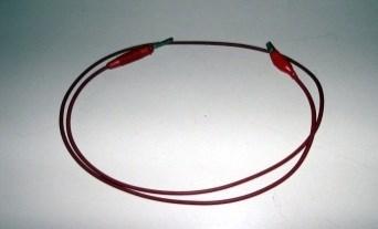
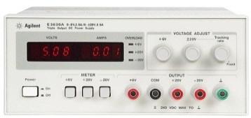
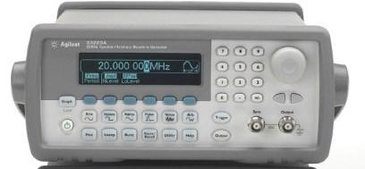
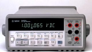
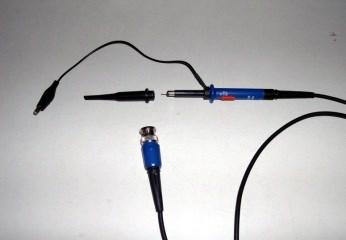
1 Measurement Bench Accessories Power supply Wave form generator Multimetre Oscilloscope
2 OSCILLOSCOPE
3 Oscilloscope (1) The oscilloscope allows to display a voltage (vertical axis - Y axis) versus time (horizontal axis - X axis). The oscilloscope can also display two voltages on both the axes (XY mode). The quantities shown on the screen are voltages. To facilitate reading of the magnitudes, on the screen there is a grid consisting of some horizontal and vertical divisions. The oscilloscopes in the laboratory are DSO3202A and MSO-X 3012T by Keysight (ex Agilent). DSO stands for Digital Storage Oscilloscope MSO stands for Mixed Signal Oscilloscope A digital oscilloscope uses an analog-to-digital converter (ADC) to convert the measured voltage into digital information. The digitized data are stored in a channel memory
4 Oscilloscope (2) Input BNC + Attenuator Amplifier ADC - DC Offset Coupling DC Level + - Comp signal Logic Channel Memory Timebase System Display DSP Yellow = Channel specific blocks Blue = System blocks DSO Block Diagram CPU System
5 Oscilloscope (3) A probe feeds the input signal into the oscilloscope where the attenuator and the amplifier are used to compensate for input levels for various voltage per division settings. The trace position is adjusted changing the DC Offset. Input BNC + Attenuator Amplifier ADC - DC Offset Coupling DC Level + - Comp signal Logic Channel Memory Timebase System Display DSP Yellow = Channel specific blocks Blue = System blocks DSO Block Diagram CPU System
6 Oscilloscope (4) The ADC provides a discrete form of the signal: in the time domain (sampling) and in the amplitude domain (quantization). The ADC converter operates continuously at the maximum sampling frequency. Input BNC + Attenuator Amplifier ADC - DC Offset Coupling DC Level + - Comp signal Logic Channel Memory Timebase System Display DSP Yellow = Channel specific blocks Blue = System blocks DSO Block Diagram CPU System
7 Oscilloscope (5) The memory is organized as a circular buffer. The write pointer advances at the rate of the ADC. write pointer Input BNC + Attenuator Amplifier ADC - DC Offset Coupling DC Level + - Comp signal Logic Channel Memory Timebase System Display DSP Yellow = Channel specific blocks Blue = System blocks DSO Block Diagram CPU System
8 Oscilloscope (6) The trigger signal, through the timebase system, causes the start of the reading cycle of the channel memory write pointer read pointer Input BNC + Attenuator Amplifier ADC - DC Offset Coupling DC Level + - Comp signal Logic Channel Memory Timebase System Display DSP Yellow = Channel specific blocks Blue = System blocks DSO Block Diagram CPU System
9 Oscilloscope (7) The trigger event defines a reading interval. The trigger determines when captured data are stored and displayed. On the display the result is a signal portion preceding and following the trigger event read pointer level 0 k n-1

10 Oscilloscope (8) problems (different trigger events) Two or more trace on the display. A trace in movement on the display read pointers level 0 k n-1 0 k n-1 0 k n-1
11 Oscilloscope (9) Newer DSOs use custom DSPs to quickly process data and then send waveform data into display memory. Input BNC + Attenuator Amplifier ADC - DC Offset Coupling DC Level + - Comp signal Logic Channel Memory Timebase System Display DSP Yellow = Channel specific blocks Blue = System blocks DSO Block Diagram CPU System
12 Oscilloscope (10) Sampling Theory The Nyquist sampling theorem states that for a limited bandwidth signal with maximum frequency f MAX, in order to reconstruct the sampled signal without aliasing, sampling frequency f S must satisfy this equation: f MAX f S /2 Nyquist frequency (f N ) Aliasing Aliasing occurs when signals are under-sampled (f MAX >f S /2). Aliasing is the signal distortion caused by low frequencies falsely reconstructed from an insufficient number of sample points.
13 Oscilloscope (11) Attenuation Oscilloscope Bandwidth and Sample Rate (1) For the sampling theory the required sample rate is f S = 2f BW assuming there are no frequency components above f MAX (f BW ) and it requires a system with an ideal brick-wall frequency response. 0 db f BW = f s /2 Frequency
14 Oscilloscope (12) Oscilloscope Bandwidth and Sample Rate (2) All oscilloscopes exhibit a low-pass frequency response typically called a Gaussian response. A Gaussian frequency response closely approximates a single-pole low-pass filter. As the frequency of an input signal increases, the Oscilloscope will begin to attenuate the input signal and then begin to make inaccurate measurements. The frequency at which a sine wave input signal is attenuated by -3dB is the oscilloscope bandwidth. But -3 db of attenuation is equivalent to approximately -30% attenuation (considering the formula 20 Log(Vo/Vi)).
15 Oscilloscope (13) Oscilloscope Bandwidth and Sample Rate (3) On the other hand, digital signals have frequency components above the fundamental frequency (square waves are made up of sine waves at the fundamental frequency and an infinite number of odd harmonics), and typically oscilloscopes (with 500MHz bandwidths and below) have a Gaussian frequency response. So, in practice, the oscilloscope sample rate should be four or more times its bandwidth: f S 4f BW. This way, there is less aliasing, and aliased frequency components have a greater amount of attenuation. f BW f s /4 Frequency


16 Oscilloscope (14) Example This slide shows two different bandwidth oscilloscopes capturing the same 100 MHz square waveform. The first oscilloscope has f BW =f Max =100MHz The second oscilloscope has f BW =5f Max =500MHz, it is able to capture up to the fifth harmonic with minimal attenuation. Input = 100-MHz Digital Clock Response using a 100-MHz BW scope Response using a 500-MHz BW scope
17 Oscilloscope (15) Oscilloscope Rise Time The oscilloscope rise time is the fastest edge speed the oscilloscope can produce and not the fastest edge speed that it can accurately measure. Closely related to an oscilloscope bandwidth specification is its rise time specification. Bandwidth Rise time Oscilloscopes with a Gaussian-type frequency response have rise time 0.35/f BW With rise time obtained from 10% to 90% of the V top.
18 Oscilloscope (17) Memory Depth and Sample Rate o For an oscilloscope's analog-to-digital converter there is a maximum sample rate. o The memory point number (memory depth) of an oscilloscope is fixed. o The actual sample rate is determined by the time of the acquisition (related to the oscilloscope horizontal time/div scale). Actual sample rate = memory depth/ acquisition time Storing 50μs of data in memory points, the actual sample rate is 1 GSa/s. Storing 50ms of data in memory points, the actual sample rate is 1 MSa/s. The actual sample rate is displayed in the summary box in the right-side information area. Oscilloscope achieves the actual sample rate decimating the unneed samples. 50 ms Sample rate = 1 MSa/s points
19 Oscilloscope Sample Rate Oscilloscope Bandwidth Memory Depth Oscilloscope Bandwidth Rise Time Actual Sample Rate
 100 MHz Bandwidth 2 analog +16 digital channels 5 GSa/s sample")
20 Oscilloscope (18) DSO3202A (Agilent) 200-MHz Bandwidth 2 analog channels 1 GSa/s sample rate MSO-X 3012T (Keysigth) 100 MHz Bandwidth 2 analog +16 digital channels 5 GSa/s sample rate

21 Oscilloscope DSO3202A (Agilent) 200-MHz Bandwidth 2 analog channels 1 GSa/s sample rate Vertical controls MENU ON/OFF Measure controls Horizontal Controls Run controls Waveform controls Entry knob Menù controls controls Power switch Display Menu defined buttons Inputs Compensation terminals
")
22 Oscilloscope DSO3202A (Agilent) Display
23 Oscilloscope MSO-X 3012T (Keysight) Vertical controls Entry knob controls Horizontal Controls Run controls Auto Scale Measure controls Waveform Keys File Keys Digital channel Power switch Inputs Softkeys Compensation terminals Analog channel Inputs Tool Keys
")
24 Oscilloscope (20) MSO-X 3012T (Keysight) Display


25 Oscilloscope (21) Softkeys The functions of these keys change based upon the menus shown on the display directly above the keys. MSO-X 3012T DSO3202A The Back/Up key moves up in the softkey menu hierarchy. At the top of the hierarchy, the key turns the menus off, and oscilloscope information is shown instead. Entry knob It is used to select items from menus and to change values. The function of the Entry knob changes based upon the current menu and softkey selections. The curved arrow symbol next the entry knob illuminates whenever the entry knob can be used to select a value. When the Entry knob symbol appears on a softkey, you can use the Entry knob, to select values. Often, rotating the Entry knob is enough to make a selection. Sometimes, you can push the Entry knob to enable or disable a selection. Pushing the Entry knob also makes popup menus disappear.


26 Oscilloscope (22) Low Frequency Compensation 1. Set the Probe menu attenuation to 10X. 2. Attach the probe tip to the probe compensation connector. 3. Press the Autoscale front panel button. 4. If the waveform is not rectangular you must compensate. 5. Through a nonmetallic tool adjust the screw located near the probe up to get a signal perfectly compensated. High Frequency Compensation 1. Using the BNC adapter, connect the probe to a square wave generator. 2. Set the square wave generator to a frequency of 1 MHz and an amplitudeof 1 Vp-p. 3. Press the Autoscale front panel button. 4. If the waveform does not appear like the Correctly Compensated waveform shown in figure, then adjust the 2 high frequency compensation adjustments on the probe for the flattest square wave possible.
![Oscilloscope (23) Vertical controls [1] and [2] analog channel on/off keys: these keys permit to switch a channel on or off, or to access a channel menu in the](/docs-images/96/127591470/images/27-0.jpg "softkeys. There is one channel on/of for each analog channel. Vertical scale knobs: for each channel there is a knob marked with.")
 of each analog channel.")
27 Oscilloscope (23) Vertical controls [1] and [2] analog channel on/off keys: these keys permit to switch a channel on or off, or to access a channel menu in the softkeys. There is one channel on/of for each analog channel. Vertical scale knobs: for each channel there is a knob marked with. Use these knobs to change the vertical sensitivity (gain) of each analog channel. Vertical position knobs: use these knobs to change the channel vertical position on the display. sensitivity (gain) of each analog channel. DSO3202A MSO-X 3012T MSO-X 3012T Mathematical operations are activated by pressing Math. The waveforms may be stored using the menu Ref.


28 Oscilloscope (24) Vertical controls: menu in the softkeys DSO3202A Channel Coupling Control Bandwidth Limit Control Probe Attenuation Control Invert Control Digital Filter Controls MSO-X 3012T To specify channel coupling To specify channel input impedance To specify bandwidth limiting To change the vertical scale knob's coarse/fine adjustment setting To invert a waveform Setting Analog Channel Probe Options
29 Oscilloscope (25) MSO-X 3012T When AC coupling is chosen, you cannot select 50Ω mode. This is done to prevent damage to the oscilloscope. AC coupling places a 10 Hz high-pass filter in series with the input waveform that removes any DC offset voltage from the waveform.
 DC for a direct connection (display full signal) GND for the check of the reference level (ground voltage) Bandwidth Limit Control - allows to remove, from the waveform examined, the high")
30 Oscilloscope (26) DSO3202A Connection control - pushing the button to the right of Coupling you can choose between three possible connections: AC for a connection via capacitor (display the AC component) DC for a direct connection (display full signal) GND for the check of the reference level (ground voltage) Bandwidth Limit Control - allows to remove, from the waveform examined, the high frequency components not relevant to the measurement made. Press the key corresponding to BW Limit function is activated (ON) and all components at frequencies greater than 20 MHz are rejected.
31 Oscilloscope (27) DSO3202A Control probe attenuation - Allows you to specify the attenuation on the probe selected. The probe attenuation control changes the attenuation factor for the probe. The attenuation factor changes the vertical scaling of the oscilloscope so that the measurement results reflect the actual voltage levels at the probe tip. Invert control - The invert control inverts the displayed waveform with respect to the ground level. Digital filter controls - Pressing the Digital Filter menu key displays the Filter Controls. The filter controls set the digital filter used to filter the sampled waveform data. The types of filters that are available are shown in the table.
32 Oscilloscope (28) Horizontal controls The oscilloscopes permit to fix only one value of time per division for all waveforms. Horizontal scale knob: it is marked with the symbol and permit to adjust the time/div (sweep speed) setting. Horizontal position knob: turn the knob marked to see through the waveform data horizontally. DSO3202A MSO-X 3012T The menu associated with the time base is activated by pressing: [Main/Delayed] (DSO3202A), [Horiz] and Zoom key (MSO-X 3012T).
33 Oscilloscope (29) Horizontal controls MSO-X 3012T You can see the captured waveform before the trigger or after the trigger. If you pan through the waveform when the oscilloscope is stopped (not in Run mode) then you are looking at the waveform data from the last acquisition taken. [Horiz] key: press this key to open the Horizontal Menu where you can select XY and Roll modes, enable or disable Zoom, enable or disable horizontal time/division fine adjustment, and select the trigger time reference point. Zoom key : Press the zoom key to split the oscilloscope display into Normal and Zoom sections without opening the Horizontal Menu. [Search] key Lets you search for events in the acquired data. [Navigate] keys Press these keys to navigate through captured data via time, search events, or segmented memory acquisition.
![Oscilloscope (30) Horizontal controls MSO-X 3012T The figure shows the Horizontal menù obtained pressing the [Horiz] key.](/docs-images/96/127591470/images/34-0.jpg "To change the horizontal time mode (Normal, XY, or Roll) To display the zoomed time base To change the horizontal scale knob's coarse/fine adjustment setting To")
34 Oscilloscope (30) Horizontal controls MSO-X 3012T The figure shows the Horizontal menù obtained pressing the [Horiz] key. To change the horizontal time mode (Normal, XY, or Roll) To display the zoomed time base To change the horizontal scale knob's coarse/fine adjustment setting To position the time reference (left, center, right)

35 Oscilloscope (31) Horizontal controls DSO3202A With Delayed command you can enable or disable delayed sweep mode. In this mode, the screen is divided into two parts, the upper part shows the original waveform while the lower part shows an enlarged view. The enlarged portion is called the delayed sweep window. and the monopole of scale and horizontal position control the relevant parameters of the waveform. The key for Time Base allows you to choose the format TY and XY. In XY format, the vertical displacement of the trace on the screen depends on the signal on channel 1 while the horizontal deviation depends on the signal on channel 2. In XY format many as the functions are not supported.

36 Oscilloscope (32) Horizontal controls MSO-X 3012T The Trig-Offset button allows you to relocate the center of the track displayed on the screen. The holdoff time is the period of waiting before starting a new trigger to change the duration of this interval is sufficient to press the key next to Holdoff and adjust the time using the knob added. Pressing the Reset holdoff the holdoff time is set to its minimum value of 100ns.

37 Oscilloscope (33) controls DSO3202A Level: it changes the voltage level of the trigger signal. Force: it forces the acquisition. 50%: voltage level of the trigger signal is set equal to the average value. Ext Trig: external trigger. Mode/Coupling: menu is activated. Mode Edge, Pulse e Video (metods) Source CH1, CH2, ext, Slope Sweep Auto, Normal Coupling AC, DC, LFrejet e HFrejet

38 Oscilloscope (34) controls MSO-X 3012T These controls determine how the oscilloscope triggers to capture data. Adjusting the Level Forcing a Edge then Edge Pulse Width Pattern OR Rise/Fall Time Nth Edge Burst Runt Setup and Hold Video Serial Zone Qualified menù
39 Oscilloscope (35) controls MSO-X 3012T You can adjust the trigger level for a selected analog channel by turning the Level knob or using the touchscreen. The [Force ] key causes a trigger (on anything) and displays the acquisition. The [] key displays the trigger menu: Press the softkey, and use the Entry knob to select Edge. Select the trigger source (Analog channel, Digital channel, External, Line, WaveGen, WaveGen Mod (FSK/FM)) Press the Slope softkey and select: Rising, Falling, Alternating and Either edges.

40 Oscilloscopio (26) Waveform Keys DSO3202A Acquire Controlls Mode: Normal, Average, Peak_detect Sampling methods:real time, Equ time Averages: Sequence: Display Controls Type: Grid: Persist: Clear: Vectors, Dots Infinite, OFF Menù Display: 1s,2s,5s Screen: Normal,Invert The Average mode allows to remove random noise from the waveforms thus improving the accuracy of the measurement. To avoid aliasing is useful acquiring type Peak Detect. Real time is recommended to observe non-periodic signals. Equ-time allows to visualize high frequency signals better. The command Sequence allows to record the waveform input from the channel 1 or 2, with a depth of acquisition of 1000 frames. Pressing the Display button the corresponding menu is shown where you can specify the display characteristics of the track and the grid.
41 Oscilloscopio (27) DSO3202A (Agilent) Real-time sampling In the real-time sampling mode, single waveforms are sampled at same intervals. The digitizer works at maximum speed to acquire as many points as possible in one sweep, and the 3000 Series oscilloscopes provide sampling rates up to 1 GSa/s. In real-time sampling the trigger event happens on a particular feature of the waveform (amplitude). In this type of data acquisition, the sample rate of the ADC determines the sample spacing and the number of points that will be displayed. Equivalent time Sampling The input signal is only sampled once per trigger. At the next triggered, a small delay is added and another sample is taken. The number of samples determines the necessary number of cycles to reproduce the waveform.
![Oscilloscope (42) Waveform keys MSO-X 3012T [Acquire] key: lets you select Normal, Peak Detect, Averaging, or High Resolution acquisition modes and use segmented memory [Display] key:](/docs-images/96/127591470/images/42-0.jpg "lets you access the menu where you can enable persistence, clear the display, and adjust the display grid (graticule) intensity.")
42 Oscilloscope (42) Waveform keys MSO-X 3012T [Acquire] key: lets you select Normal, Peak Detect, Averaging, or High Resolution acquisition modes and use segmented memory [Display] key: lets you access the menu where you can enable persistence, clear the display, and adjust the display grid (graticule) intensity. [Touch] key: press this key to disable/enable the touchscreen.
43 Oscilloscope (43) MSO-X 3012T To select the acquisition mode: 1 Press the [Acquire] key on the front panel. 2 In the Acquire Menu, press the Acq Mode softkey; then, turn the Entry knob to select the acquisition mode. The Infinii Vision oscilloscopes have the following acquisition modes: Normal at slower (greater) time/div settings, normal decimation occurs, and there is no averaging. Use this mode for most waveforms. Peak Detect at slower (greater) time/div settings, the maximum and minimum samples in the effective sample period are stored. Use this mode for displaying narrow pulses that occur infrequently. Averaging this mode permit to average multiple acquisitions together to reduce noise and increase vertical resolution (at all time/div settings). Averaging requires a stable trigger. High Resolution at slower time/div settings, all samples in the effective sample period are averaged and the average value is stored. Use this mode for reducing random noise. In MSO-X 3012T model you can use only the Realtime sampling. The Equivalent time sampling option is present in MSO-X 3102T, MSO-X 3104T model.
44 Oscilloscope (41) Run Control keys When the [Run/Stop] key is green, the oscilloscope is acquiring data (is running) when trigger conditions are met. To stop acquiring data, press [Run/Stop]. When the [Run/Stop] key is red, data acquisition is stopped. To start acquiring data, press [Run/Stop]. To capture and display a single acquisition (whether the oscilloscope is running or stopped), press [Single]. The [Single] key is yellow until the oscilloscope triggers. DSO3202A MSO-X 3012T
45 Oscilloscope (36) DSO3202A Autoscale Control The Autoscale key is used to retrieve and set automatically the oscilloscope controls necessary for a good display of the waveform at the input. Save and Recall Controlls Save/Recall: Waveforms, Setups Default Setup Waveform: 1-10 Setup: 1-10 Load Save Utility Controlls Mask Test: Menù I/OSetup Menù Language: English,.. Sound:, System Info Self-Cal Self-Test
46 Oscilloscope (45) Autoscale Control MSO-X 3012T Tools keys : [Utility] key the utility Menu, which lets you configure the oscilloscope's I/O settings, use the file explorer, set preferences, access the service menu, and choose other options. [Quick Action] key Press this key to perform the selected quick action: measure all snapshot, print, save, recall, freeze display, and more. [Wave Gen] key Press this key to access waveform generator functions. [Analyze] key To access analysis features like: - Measurement threshold setting. - level setting. - Video trigger automatic set up and display. - Counter (DVMCTR). - Digital voltmeter (DVMCTR) - Mask testing - The DSOX3PWR power measurement and analysis application. File keys [Save/Recall] key: it is used to save or recall a waveform or setup. [Print] key: it opens the Print Configuration Menu so you can print the displayed waveforms.

47 Oscilloscope (28) Measure Controls DSO3202A Meas Sourcee: Voltage: Time Clear Display All: CH1, CH2 Vpp,Vmax, Vmin, Vavg,... Freq, Period, OFF, ON Cursor Manual: Menù Track: Menù Auto Measure: Menù Meas button on the front panel activates the automatic measurement system, in particular this enables oscilloscope to perform 20 different measures including: Vpp, Vmax, Vmin, Vamp, Vavg, Vrms, Freq, Period, risetime and Fall Time. The Cursor button on the front panel activates the menu corresponding to the measures concerning the marker. There are three modes: Manual, Track and Auto Measure. Manual, the screen shows two parallel cursors that can be moved on the track in order to obtain the measures of voltage or of time desired. The values corresponding to the cursors are shown in the upper part of the screen. Track, two sliders are automatically activated that can be adjusted using the added knob. Auto Measure, available when the measurement system is automatically activated, the oscilloscope displays the cursor in relation to the latest measures used.
48 Oscilloscope (44) Measure controls MSO-X 3012T The measure controls consist of: Cursors knob: Push this knob to select cursors from a popup menu. Then, after the popup menu closes (either by timeout or by pushing the knob again), rotate the knob to adjust the selected cursor position. [Cursors] key: Press this key to open a menu that lets you select the cursors mode and source. [Meas] key: Press this key to access a set of predefined measurements.
49 Oscilloscope (29) DSO3202A (Agilent) Voltage measurements: Vpp Vmax Vmin Vavg Vamp Vtop Vbase Vrms Overshoot Preshoot (Peak-to-Peak Voltage) (Maximum Voltage) (Minimum Voltage) (Average Voltage) (Amplitude Voltage = Vtop - Vbase) (Top Voltage) (Base Voltage) (True Root-Mean-Square Voltage) (Measure the overshoot voltage in percent (Vmax-Vtop)/Vamp. Overshoot is a waveform distortion which follows a major edge transition) (Measure the preshoot voltage in percent (Vmin-Vbase)/Vamp,. Preshoot is a waveform distortion which precedes a major edge transition)
50 Oscilloscopio (30) 3202A (Agilent) Time Measurements: Frequency Period Rise Time Fall Time +Width -Width +Duty -Duty Delay 1 2 Delay 1 2
51 Left display side Left display side Oscilloscope (31) DSO3202A (Agilent) Delay 1-2, rising edges Delay 1-2, falling edges Dt a 50% Channel 1 Channel 1 Dt a 50% 50% Channel 2 50% Channel 2 t 1 t 2 Delay From channel 1 to channel 2 rising edges ( t 2 -t 1 ) t 1 t 2 Delay From channel 1 to channel 2 Falling edges ( = t 2 -t 1 ) t 2 -t 1 =Dt a >0
52 Left display side Oscilloscope (32) DSO3202A (Agilent) Delay 1-2, rising edges 50% Dt a Channel 1 t 2 -t 1 =-Dt b <0 Dt a =T-Dt b >0 50% 50% Channel 2 t 2 t 1 Delay From channel 1 to channel 2 rising edges ( = t2-t1)

53 Oscilloscope (29) DSO3202A (Agilent) The math functions control allows the selection of the math functions add, subtract, multiply, and FFT (Fast Fourier Transform) for CH1 and CH2. The mathematical result can be measured visually and also using the cursor controls. The FFT math function mathematically converts a time-domain waveform into its frequency components. The FFT of a waveform that has a DC component or offset can cause incorrect FFT waveform magnitude values. To minimize the DC component, choose AC Coupling on the source waveform. To reduce random noise and aliasing components in repetitive or single-shot waveforms, set the oscilloscope acquisition mode to averaging. To display FFT waveforms with a large dynamic range, use the dbvrms scale. The dbvrms scale displays component magnitudes using a log scale.

54 Oscilloscope (30) DSO3202A (Agilent) Selecting an FFT Window FFT based measurements are subject to errors from an effect known as leakage. This effect occurs when the FFT is computed from of a block of data which is not periodic. To correct this problem appropriate windowing functions must be applied. The window is shaped so that it is exactly zero at the beginning and end of the data block and has some special shape in between. For the 3202A there are 4 FFT windows. Each window has trade-offs between frequency resolution and amplitude accuracy. Your source waveform characteristics along with your measurement priorities help determine which window to use.
Agilent 3000 Series Oscilloscopes. User s and Service Guide
 Agilent 3000 Series Oscilloscopes User s and Service Guide A Notices Agilent Technologies, Inc. 2005, 2007 No part of this manual may be reproduced in any form or by any means (including electronic storage
54645D. Mixed Signal Oscilloscope
 54645D Mixed Signal Oscilloscope Page 1 of 42 Instructions for the use of the 54645D Mixed Signal Oscilloscope This pamphlet is intended to give you (the student) an overview on the use of the 54645D Mixed
Combinational logic: Breadboard adders
 ! ENEE 245: Digital Circuits & Systems Lab Lab 1 Combinational logic: Breadboard adders ENEE 245: Digital Circuits and Systems Laboratory Lab 1 Objectives The objectives of this laboratory are the following:
Agilent 1000 Series Oscilloscopes. User s Guide
 Agilent 1000 Series Oscilloscopes User s Guide Notices Agilent Technologies, Inc. 2008-2009 No part of this manual may be reproduced in any form or by any means (including electronic storage and retrieval
User Manual Series. Digital Storage Oscilloscope 6810, 6806, March Copyright Protek Test & Measurement 2005 All Rights Reserved
 User Manual March 2005 6800 Series Digital Storage Oscilloscope 6810, 6806, 6804 Copyright Protek Test & Measurement 2005 All Rights Reserved Copyright Protek Test & Measurement 2005 All Rights Reserved.
Agilent 3000 Series Oscilloscopes
 Agilent 3000 Series Oscilloscopes User s and Service Guide Agilent Technologies In This Book This book gives you the information you need to begin using the 3000 Series Oscilloscopes. It contains the following
Getting Started. MSO/DPO Series Oscilloscopes. Basic Concepts
 Getting Started MSO/DPO Series Oscilloscopes Basic Concepts 001-1523-00 Getting Started 1.1 Getting Started What is an oscilloscope? An oscilloscope is a device that draws a graph of an electrical signal.
Agilent 1000B Series Oscilloscopes. User s Guide
 Agilent 1000B Series Oscilloscopes User s Guide s1 Notices Agilent Technologies, Inc. 2008-2009, 2012 No part of this manual may be reproduced in any form or by any means (including electronic storage
Agilent InfiniiVision 2000 X-Series Oscilloscopes. User's Guide
 Agilent InfiniiVision 2000 X-Series Oscilloscopes User's Guide Notices Agilent Technologies, Inc. 2005-2011 No part of this manual may be reproduced in any form or by any means (including electronic storage
Agilent InfiniiVision 3000 X-Series Oscilloscopes. User's Guide
 Agilent InfiniiVision 3000 X-Series Oscilloscopes User's Guide Notices Agilent Technologies, Inc. 2005-2011 No part of this manual may be reproduced in any form or by any means (including electronic storage
EXPERIMENT NUMBER 2 BASIC OSCILLOSCOPE OPERATIONS
 1 EXPERIMENT NUMBER 2 BASIC OSCILLOSCOPE OPERATIONS The oscilloscope is the most versatile and most important tool in this lab and is probably the best tool an electrical engineer uses. This outline guides
LAB I. INTRODUCTION TO LAB EQUIPMENT
 1. OBJECTIVE LAB I. INTRODUCTION TO LAB EQUIPMENT In this lab you will learn how to properly operate the oscilloscope Agilent MSO6032A, the Keithley Source Measure Unit (SMU) 2430, the function generator
Keysight 1000B Series Oscilloscopes. User s Guide
 Keysight 1000B Series Oscilloscopes User s Guide Notices Keysight Technologies, Inc. 2008-2009, 2012, 2014, 2017 No part of this manual may be reproduced in any form or by any means (including electronic
Specifications for DS1000CA Series
 Revised December, 2009 RIGOL Specifications for DS1000CA Series All specifications apply to the DS1000CA Series Oscilloscopes unless noted otherwise. To meet these specifications, two conditions must first
Keysight InfiniiVision 2000 X-Series Oscilloscopes. User's Guide
 Keysight InfiniiVision 2000 X-Series Oscilloscopes User's Guide Notices Keysight Technologies, Inc. 2005-2017 No part of this manual may be reproduced in any form or by any means (including electronic
User s Guide RIGOL. DS1000E, DS1000D Series Digital Oscilloscopes DS1102E, DS1052E, DS1102D, DS1052D. Publication number UGA July 2009
 User s Guide RIGOL Publication number UGA07111-1110 July 2009 DS1000E, DS1000D Series Digital Oscilloscopes DS1102E, DS1052E, DS1102D, DS1052D All Rights Reserved 1. All Rights Reserved 2. RIGOL products
HP 16533A 1-GSa/s and HP 16534A 2-GSa/s Digitizing Oscilloscope
 User s Reference Publication Number 16534-97009 February 1999 For Safety Information, Warranties, and Regulatory Information, see the pages behind the Index Copyright Hewlett-Packard Company 1991 1999
OL-612 PORTABLE MIXED SIGNAL DIGITAL STORAGE OSCILLOSCOPE
 OL-612 PORTABLE MIXED SIGNAL DIGITAL STORAGE OSCILLOSCOPE Version Date Software Version 1.0 October 2014 4.2-0 MI2012-99 Washington Street Melrose, MA 02176 Phone 781-665-1400 Toll Free 1-800-517-8431
User s Guide RIGOL. DS1000CA Series Digital Oscilloscopes DS1302CA, DS1202CA, DS1102CA, DS1062CA. Publication number DS1000CA April 2008
 User s Guide RIGOL Publication number DS1000CA-080512 April 2008 DS1000CA Series Digital Oscilloscopes DS1302CA, DS1202CA, DS1102CA, DS1062CA Copyright 1998-2008 RIGOL Technologies, Inc. All Rights Reserved
RIGOL Data Sheet. DS1000E, DS1000D Series Digital Oscilloscopes DS1102E, DS1052E, DS1102D, DS1052D. Product Overview. Easy to Use Design.
 RIGOL Data Sheet DS1000E, DS1000D Series Digital Oscilloscopes DS1102E, DS1052E, DS1102D, DS1052D Product Overview The DS1000E, DS1000D series instruments are economical, high-performance digital oscilloscopes.
Keysight InfiniiVision 1000 X-Series Oscilloscopes. User's Guide
 Keysight InfiniiVision 1000 X-Series Oscilloscopes User's Guide Notices Keysight Technologies, Inc. 2005-2018 No part of this manual may be reproduced in any form or by any means (including electronic
Agilent N2740A Education Training Kit for 1000 Series Oscilloscopes
 Agilent N2740A Education Training Kit for 1000 Series Oscilloscopes Lab Manual A Notices Agilent Technologies, Inc. 2008 No part of this manual may be reproduced in any form or by any means (including
EE 201 Function / Arbitrary Waveform Generator and Oscilloscope Tutorial
 EE 201 Function / Arbitrary Waveform Generator and Oscilloscope Tutorial 1 This is a programmed learning instruction manual. It is written for the Agilent DSO3202A Digital Storage Oscilloscope. The prerequisite
DSO5000P Series Digital Storage Oscilloscope User Manual. (Version 1.1)
") DSO5000P Series Digital Storage Oscilloscope User Manual (Version 1.1) Contents Contents Contents... i Chapter 1 Safety Tips... 1 1.1 General Safety Summary... 1 1.2 Safety Terms and Symbols... 2 1.3 Terms
DSO5000P Series Digital Storage Oscilloscope User Manual (Version 1.1) Contents Contents Contents... i Chapter 1 Safety Tips... 1 1.1 General Safety Summary... 1 1.2 Safety Terms and Symbols... 2 1.3 Terms
LAB I. INTRODUCTION TO LAB EQUIPMENT
 LAB I. INTRODUCTION TO LAB EQUIPMENT 1. OBJECTIVE In this lab you will learn how to properly operate the basic bench equipment used for characterizing active devices: 1. Oscilloscope (Keysight DSOX 1102A),
ME 365 EXPERIMENT 1 FAMILIARIZATION WITH COMMONLY USED INSTRUMENTATION
 Objectives: ME 365 EXPERIMENT 1 FAMILIARIZATION WITH COMMONLY USED INSTRUMENTATION The primary goal of this laboratory is to study the operation and limitations of several commonly used pieces of instrumentation:
Chapter 5 : Specifications
 Chapter 5 : Specifications All specifications apply to the DS1000B Series Oscilloscopes and a probe with the Attenuation switch set to 10X unless noted otherwise. To meet these specifications, two conditions
Specifications. Specifications and Characteristics Specifications
 Specifications and Specifications Specifications All specifications are warranted. Specifications are valid after a 30-minute warm-up period and ±5 C from last calibration temperature. Bandwidth (-3dB)
Agilent Technologies 3000 Series Oscilloscopes
 Agilent Technologies 3000 Series Oscilloscopes Data Sheet Full-featured oscilloscopes for the smallest budgets Features: 60 to 200 MHz bandwidths 1 GSa/s maximum sample rate Large 15-cm (5.7-in) color
User Manual RIGOL. DS1000KCA Series Digital Oscilloscopes DS1302CA, DS1202CA, DS1102CA, DS1062CA. Publication number DS1KCA June 2007
 User Manual RIGOL Publication number DS1KCA-070712 June 2007 DS1000KCA Series Digital Oscilloscopes DS1302CA, DS1202CA, DS1102CA, DS1062CA Copyright RIGOL Technologies, Inc. 2007 All Rights Reserved Copyright
DS1000B Series Digital Oscilloscopes
 Product Overview DS1000B series oscilloscopes are designed with four analog channels and 1 external trigger channel, which can capture multi-channel signal simultaneously and meet industrial needs. The
Hantek. Hantek Electronic co.,ltd. No.177 zhuzhou road(huite industry city), QingDao,China
, QingDao,China") Hantek Hantek Electronic co.,ltd. No.177 zhuzhou road(huite industry city), QingDao,China DSO1000SERIES HANDHELD OSCILLOSCOPE USER S MANUAL 1060/1200/1600/1600H www.hantek.com.cn DSO1000 SERIES HANDHELD
Hantek Hantek Electronic co.,ltd. No.177 zhuzhou road(huite industry city), QingDao,China DSO1000SERIES HANDHELD OSCILLOSCOPE USER S MANUAL 1060/1200/1600/1600H www.hantek.com.cn DSO1000 SERIES HANDHELD
MSO-5000B Mixed Storage Oscilloscope User Manual
 MSO-5000B Mixed Storage Oscilloscope User Manual Contents Contents CONTENTS... I COPYRIGHT DECLARATION... IV CHAPTER 1 SAFETY TIPS... 1 1.1 GENERAL SAFETY SUMMARY... 1 1.2 SAFETY TERMS AND SYMBOLS... 2
Introduction to Oscilloscopes Instructor s Guide
 Introduction to Oscilloscopes A collection of lab exercises to introduce you to the basic controls of a digital oscilloscope in order to make common electronic measurements. Revision 1.0 Page 1 of 25 Copyright
Digital 20MHz and 60MHz Oscilloscopes
 User's Guide Digital 20MHz and 60MHz Oscilloscopes Model MS460-60MHz Model MS420-20MHz 1 INTRODUCTION Congratulations on your purchase of the Extech Digital Oscilloscope. This manual is divided into two
Basic Communication Laboratory Manual. Shimshon Levy&Harael Mualem
 Basic Communication Laboratory Manual Shimshon Levy&Harael Mualem September 2006 CONTENTS 1 The oscilloscope 2 1.1 Objectives... 2 1.2 Prelab... 2 1.3 Background Theory- Analog Oscilloscope...... 3 1.4
Agilent 54621A/22A/24A/41A/42A Oscilloscopes and Agilent 54621D/22D/41D/42D Mixed-Signal Oscilloscopes
 User s Guide Publication Number 54622-97036 September 2002 For Safety Information and Regulatory information, see the pages behind the Index. Copyright Agilent Technologies 2000-2002 All Rights Reserved
Publication Number August For Safety information, Warranties, and Regulatory information, see the pages behind the index
 User s Guide Publication Number 54657-97019 August 2000 For Safety information, Warranties, and Regulatory information, see the pages behind the index Copyright Agilent Technologies 1991-1996, 2000 All
User s Guide RIGOL. DS1000E, DS1000D Series Digital Oscilloscopes DS1102E, DS1052E, DS1102D, DS1052D. Publication number UGA July 2008
 User s Guide RIGOL Publication number UGA07107-1110 July 2008 DS1000E, DS1000D Series Digital Oscilloscopes DS1102E, DS1052E, DS1102D, DS1052D All Rights Reserved All Rights Reserved RIGOL products are
DSO-1102 USB DSO-2202 USB
 USER S MANUAL DSO-1102 USB Content General Safety Summary... 1 Chapter 1 Getting Start... 3 1.1 System Requirement... 4 1.2 Install Software... 5 1.3 Install Drive... 8 1.4 General Check... 14 1.5 Probe
DS1102E, DS1052E, DS1102D, DS1052D
 RIGOL Data Sheet DS1000E, DS1000D Series Digital Oscilloscopes DS1102E, DS1052E, DS1102D, DS1052D Product Overview DS1000E, DS1000D series are kinds of economical digital oscilloscope with high-performance.
Product Channels Bandwidth Sampling Rate Memory Resolution
 Nov@tek Oscilloscope and Spectrum Analyzer Introduction The 4-channel digital storage oscilloscope at an outstanding price! When connected to PC with USB2.0 interface, you get a fully-featured storage
EENG-201 Experiment # 4: Function Generator, Oscilloscope
 EENG-201 Experiment # 4: Function Generator, Oscilloscope I. Objectives Upon completion of this experiment, the student should be able to 1. To become familiar with the use of a function generator. 2.
Notes on Experiment #1
 Notes on Experiment #1 Bring graph paper (cm cm is best) From this week on, be sure to print a copy of each experiment and bring it with you to lab. There will not be any experiment copies available in
Faculty of Engineering, Thammasat University
 Faculty of Engineering, Thammasat University Experiment 6: Oscilloscope (For room 506) Objectives: 1. To familiarize you with the Oscilloscope and Function Generator User Manual: Oscilloscope 1 5 9 4 7
OD-610 OD-620 DIGITAL OSCILLOSCOPE
 OD-610 OD-620 DIGITAL OSCILLOSCOPE Version Date Software Version 1.1 September 2014 2.1.0.3-0 MI2010-99 Washington Street Melrose, MA 02176 Phone 781-665-1400 Toll Free 1-800-517-8431 Visit us at www.testequipmentdepot.com
Reference. TDS6000 Series Digital Storage Oscilloscopes
 Reference TDS6000 Series Digital Storage Oscilloscopes 07-703-0 077030 To Use the Front Panel You can use the dedicated, front-panel knobs and buttons to do the most commonly performed operations. Turn
User s Guide RIGOL. DS1000CA Series Digital Oscilloscopes DS1302CA, DS1202CA, DS1102CA, DS1062CA. Publication number UGA Oct.
 User s Guide RIGOL Publication number UGA03106-1110 Oct. 2008 DS1000CA Series Digital Oscilloscopes DS1302CA, DS1202CA, DS1102CA, DS1062CA 2007 RIGOL Technologies, Inc. All Rights Reserved. 2007 RIGOL
RIGOL Data Sheet. DS1000E, DS1000D Series Digital Oscilloscopes DS1102E, DS1052E, DS1102D, DS1052D. Product Overview. Applications. Easy to Use Design
 RIGOL Data Sheet DS1000E, DS1000D Series Digital Oscilloscopes DS1102E, DS1052E, DS1102D, DS1052D Product Overview DS1000E, DS1000D series are kinds of economical digital oscilloscope with high-performance.
U1604A Handheld Oscilloscopes, 40 MHz
 Products & Services Technical Support Buy Industries About Agilent Search: All Test & Measurement Go United States Home >... > Oscilloscopes > U1600A Series handheld oscilloscopes (2 models) > U1604A Handheld
Help Volume Agilent Technologies. All rights reserved. Instrument: Agilent Technologies 16533/34A Digitizing Oscilloscope
 Help Volume 1992-2002 Agilent Technologies. All rights reserved. Instrument: Agilent Technologies 16533/34A Digitizing Oscilloscope Agilent Technologies 16533/34A Digitizing Oscilloscope The Agilent Technologies
U1571A Ni-MH Battery Pack for U1600A Handheld Oscilloscopes
 United States Home >... > Oscilloscope Accessories > U1600 Series Oscilloscope Accessories > U1571A Ni-MH Battery Pack for U1600A Handheld Oscilloscopes Key Specifications Features Ni-MH Battery Pack,
DST Series B Type Digital Storage Oscilloscope User Manual
 DST Series B Type Digital Storage Oscilloscope User Manual Contents Contents Contents... i Copyright Declaration... iv Chapter 1 Safety Tips... 1 1.1 General Safety Summary... 1 1.2 Safety Terms and Symbols...
DSO4000 Series Digital Storage Oscilloscope User Manual. (Version 1.3)
") DSO4000 Series Digital Storage Oscilloscope User Manual (Version 1.3) Contents Contents... i Safety Tips... 1 General Safety Summary... 1 Safety Terms and Symbols... 2 Product Scrapping... 2 Brief Introduction
DSO4000 Series Digital Storage Oscilloscope User Manual (Version 1.3) Contents Contents... i Safety Tips... 1 General Safety Summary... 1 Safety Terms and Symbols... 2 Product Scrapping... 2 Brief Introduction
UCE-DSO210 DIGITAL OSCILLOSCOPE USER MANUAL. FATIH GENÇ UCORE ELECTRONICS REV1
 UCE-DSO210 DIGITAL OSCILLOSCOPE USER MANUAL FATIH GENÇ UCORE ELECTRONICS www.ucore-electronics.com 2017 - REV1 Contents 1. Introduction... 2 2. Turn on or turn off... 3 3. Oscilloscope Mode... 3 3.1. Display
Hantek 365B PC-Based 6000 Count USB Data Logging True RMS Digital MultiMeter
 Hantek 365B PC-Based 6000 Count USB Data Logging True RMS Digital MultiMeter Sold and supported in the United States, buy the Hantek 365B at CircuitSpecialists.com USER S MANUAL Hantek6102BE Hantek6212BE
UTD1000 User Manual. Table of Contents
 Table of Contents Introduction : UTD1000 Series Digital Storage Oscilloscope Chapter 1 User Guide 1. Getting to know your UTD1000 Digital Storage Oscilloscope 2. General Inspection 3. Functional Check
Group CHAUVIN ARNOUX 190, rue Championnet F PARIS Tel. +33 (0) Fax +33 (0) X03583A00 - Ed.
 Fax +33 (0) X03583A00 - Ed.") Digital Oscilloscopes XDO2025 2-channel - 25 MHz XDO2040 2-channel - 40 MHz Userr s manuall Group CHAUVIN ARNOUX 190, rue Championnet F - 75018 - PARIS Tel. +33 (0)1.44.85.44.85 - Fax +33 (0)1.46.27.73.89
Digital Oscilloscopes XDO2025 2-channel - 25 MHz XDO2040 2-channel - 40 MHz Userr s manuall Group CHAUVIN ARNOUX 190, rue Championnet F - 75018 - PARIS Tel. +33 (0)1.44.85.44.85 - Fax +33 (0)1.46.27.73.89
P a g e 1 ST985. TDR Cable Analyzer Instruction Manual. Analog Arts Inc.
 P a g e 1 ST985 TDR Cable Analyzer Instruction Manual Analog Arts Inc. www.analogarts.com P a g e 2 Contents Software Installation... 4 Specifications... 4 Handling Precautions... 4 Operation Instruction...
Experiment #2: Introduction to Lab Equipment: Function Generator, Oscilloscope, and Multisim
 SCHOOL OF ENGINEERING AND APPLIED SCIENCE DEPARTMENT OF ELECTRICAL AND COMPUTER ENGINEERING ECE 2110: CIRCUIT THEORY LABORATORY Experiment #2: Introduction to Lab Equipment: Function Generator, Oscilloscope,
User s Guide RIGOL. DS1000B Series Digital Oscilloscopes DS1062/4B,DS1102/4B,DS1202/4B. Publication number UGA July 2008
 User s Guide RIGOL Publication number UGA04107-1210 July 2008 DS1000B Series Digital Oscilloscopes DS1062/4B,DS1102/4B,DS1202/4B All Rights Reserved All Rights Reserved. RIGOL products are protected by
Agilent 54621A/22A/24A Oscilloscopes and Agilent 54621D/22D Mixed-Signal Oscilloscopes
 User s Guide Publication Number 54622-97014 August 2000 For Safety Information, Warranties, and Regulatory information, see the pages behind the Index. Copyright Agilent Technologies 2000 All Rights Reserved
DSO8000E SERIES HANDHELD OSCILLOSCOPE
 DSO8000E SERIES HANDHELD OSCILLOSCOPE USER S MANUAL 8072E/8102E/8152E/8202E (V1.0.1) Contents Contents Contents... i Copyright Declaration... iii Chapter 1 Safety Tips... 1 1.1 General Safety Summary...
DSO1000E/F Series Digital Storage Oscilloscope User Manual. (Version 1.3)
") DSO1000E/F Series Digital Storage Oscilloscope User Manual (Version 1.3) Copyright Declaration All rights reserved; no part of this document may be reproduced or transmitted in any form or by any means,
DSO1000E/F Series Digital Storage Oscilloscope User Manual (Version 1.3) Copyright Declaration All rights reserved; no part of this document may be reproduced or transmitted in any form or by any means,
UCE-DSO212 DIGITAL OSCILLOSCOPE USER MANUAL. UCORE ELECTRONICS
 UCE-DSO212 DIGITAL OSCILLOSCOPE USER MANUAL UCORE ELECTRONICS www.ucore-electronics.com 2017 Contents 1. Introduction... 2 2. Turn on or turn off... 3 3. Oscilloscope Mode... 4 3.1. Display Description...
Introduction to Lab Instruments
 ECE316, Experiment 00, 2017 Communications Lab, University of Toronto Introduction to Lab Instruments Bruno Korst - bkf@comm.utoronto.ca Abstract This experiment will review the use of three lab instruments
Agilent Technologies 3000 Series Oscilloscopes
 Agilent Technologies 3000 Series Oscilloscopes Data Sheet Full-featured oscilloscopes for the smallest budgets Features: 60 to 200 MHz bandwidths 1 GSa/s maximum sample rate Large 15-cm (5.7-in) color
EE EXPERIMENT 1 (2 DAYS) BASIC OSCILLOSCOPE OPERATIONS INTRODUCTION DAY 1
 BASIC OSCILLOSCOPE OPERATIONS INTRODUCTION DAY 1") EE 2101 - EXPERIMENT 1 (2 DAYS) BASIC OSCILLOSCOPE OPERATIONS INTRODUCTION The oscilloscope is the most versatile and most important tool in this lab and is probably the best tool an electrical engineer
EE 2101 - EXPERIMENT 1 (2 DAYS) BASIC OSCILLOSCOPE OPERATIONS INTRODUCTION The oscilloscope is the most versatile and most important tool in this lab and is probably the best tool an electrical engineer
Agilent Technologies 3000 Series Oscilloscopes
 Agilent Technologies 3000 Series Oscilloscopes Data Sheet The performance and features you need at the industry s lowest price Features: 60 to 200 MHz bandwidths 1 GSa/s maximum sample rate Large 15-cm
Advanced Lab LAB 6: Signal Acquisition & Spectrum Analysis Using VirtualBench DSA Equipment: Objectives:
 Advanced Lab LAB 6: Signal Acquisition & Spectrum Analysis Using VirtualBench DSA Equipment: Pentium PC with National Instruments PCI-MIO-16E-4 data-acquisition board (12-bit resolution; software-controlled
Oscilloscope and Function Generators
 MEHRAN UNIVERSITY OF ENGINEERING AND TECHNOLOGY, JAMSHORO DEPARTMENT OF ELECTRONIC ENGINEERING ELECTRONIC WORKSHOP # 02 Oscilloscope and Function Generators Roll. No: Checked by: Date: Grade: Object: To
PeakTech 1210/1215. Bedienungsanleitung / operation manual. Digital Oszilloskop mit Farbdisplay Digital Oscilloscope / with colour display
 PeakTech 1210/1215 Bedienungsanleitung / operation manual Digital Oszilloskop mit Farbdisplay Digital Oscilloscope / with colour display 1. Safety Precautions This product complies with the requirements
Oscilloscope Fundamentals. For Electrical Engineering and Physics Undergraduate Students
 Oscilloscope Fundamentals For Electrical Engineering and Physics Undergraduate Students Agenda What is an oscilloscope? Probing basics (low-frequency model) Making voltage and timing measurements Properly
MULT SWP X1K K VERN START FREQ DURATION AMPLITUDE 0 TTL OUT RAMP
 Signal Generators This document is a quick reference guide to the operation of the signal generators available in the laboratories. Major functions will be covered, but some features such as their sweep
PeakTech 1190/1230. Operation manual. Digital Oscilloscope / with 16-CH logic analyzer
 PeakTech 1190/1230 Operation manual Digital Oscilloscope / with 16-CH logic analyzer 1. Safety Precautions This product complies with the requirements of the following European Community Directives: 2004/108/EC
What the LSA1000 Does and How
 2 About the LSA1000 What the LSA1000 Does and How The LSA1000 is an ideal instrument for capturing, digitizing and analyzing high-speed electronic signals. Moreover, it has been optimized for system-integration
LeCroy 9304A, 9304AM Digital Oscilloscopes 200 MHz Bandwidth, 100 MS/s. Main Features
 LeCroy 9304A, 9304AM Digital Oscilloscopes 200 MHz Bandwidth, 100 MS/s Main Features Four Channels 50k and 200k Point Records DOS Compatible Floppy Disk, PCMCIA portable hard drive and Memory Card Options
USER S MANUAL 1062S/1122S/1152S/1202S
 DSO1000S SERIES HANDHELD OSCILLOSCOPE USER S MANUAL 1062S/1122S/1152S/1202S (V 1.0.1) Contents Contents Contents... i Copyright Declaration... iii Chapter 1 Safety Tips... 1 1.1 General Safety Summary...
User Manual RIGOL. DS1000 Series Digital Oscilloscopes DS1000CD, DS1000C, DS1000MD, DS1000M. Publication number DS March 2006
 User Manual RIGOL Publication number DS1-061107 March 2006 DS1000 Series Digital Oscilloscopes DS1000CD, DS1000C, DS1000MD, DS1000M Copyright RIGOL Technologies, Inc. 2006 All Rights Reserved Copyright
PC Based Digital Oscilloscope
 USER S MANUAL DSO-2074G Content General Safety Summary... 1 Chapter 1 Getting Start... 2 1.1 System Requirement... 3 1.2 Install Software... 4 1.3 Install Driver... 7 1.4 General Features... 10 1.5 General
DS 6000 Specifications
 DS 6000 Specifications All the specifications are guaranteed except the parameters marked with Typical and the oscilloscope needs to operate for more than 30 minutes under the specified operation temperature.
Performance Characteristics
 The performance characteristics describe the typical performance of the oscilloscope. You will notice that some of the characteristics are marked as tested, these are values that you can verify with the
Introduction to Oscilloscopes
 Introduction to Oscilloscopes A Hands On Laboratory Guide to Oscilloscopes using the Rigol DS1104Z By: Tom Briggs, Department of Computer Science & Engineering Shippensburg University of Pennsylvania Introduction
RS Pro HANDY OSCILLOSCOPE RSHS800 SERIES
 Product Datasheet ENGLISH Stock No: 1236454 1236455 1236456 1236457 RS Pro HANDY OSCILLOSCOPE RSHS800 SERIES Application Domain Outdoor measure Circuit measure Wind power, PV power and other new energy
RS Pro HANDY OSCILLOSCOPE RSHS800 SERIES
 Product Datasheet ENGLISH Stock No: 1236454 1236455 1236456 1236457 RS Pro HANDY OSCILLOSCOPE RSHS800 SERIES Application Domain Outdoor measure Circuit measure Wind power, PV power and other new energy
Fourier Theory & Practice, Part II: Practice Operating the Agilent Series Scope with Measurement/Storage Module
 Fourier Theory & Practice, Part II: Practice Operating the Agilent 54600 Series Scope with Measurement/Storage Module By: Robert Witte Agilent Technologies Introduction: This product note provides a brief
Divide. MHz models) waveform record
 waveform record") The 2550 series digital storage oscilloscopes provide high performance and value in 2-channel and 4-channel configurations. With bandwidth from 70 MHz to 300 MHz and 2 GSa/s sample rates, these oscilloscopes
The 2550 series digital storage oscilloscopes provide high performance and value in 2-channel and 4-channel configurations. With bandwidth from 70 MHz to 300 MHz and 2 GSa/s sample rates, these oscilloscopes
USER S MANUAL DIGITAL OSCILLOSCOPE DSO-2020 USB
 USER S MANUAL DIGITAL OSCILLOSCOPE DSO-2020 USB Content General Safety Summary... 1 Chapter 1 Getting Start... 2 1.1 System Requirement... 3 1.2 Install Software... 4 1.3 Install Driver... 7 1.4 General
Digital Storage Oscilloscopes
 Model: 2540B, 2542B, 2540B-GEN, 2542B-GEN Digital Storage Oscilloscopes USER MANUAL 2 Safety Summary The following safety precautions apply to both operating and maintenance personnel and must be observed
PHYSICS 171 UNIVERSITY PHYSICS LAB II. Experiment 4. Alternating Current Measurement
 PHYSICS 171 UNIVERSITY PHYSICS LAB II Experiment 4 Alternating Current Measurement Equipment: Supplies: Oscilloscope, Function Generator. Filament Transformer. A sine wave A.C. signal has three basic properties:
Agilent 81133A/81134A
 Agilent 81133A/81134A Performance Verification Rev. 2.3, Dec. 2009 Agilent Technologies Introduction Use these tests if you want to check that the Agilent 81133A / 81134A Pulse / Pattern Generator is
University of Utah Electrical & Computer Engineering Department ECE 2210/2200 Lab 4 Oscilloscope
 University of Utah Electrical & Computer Engineering Department ECE 2210/2200 Lab 4 Oscilloscope Objectives 1 Introduce the Oscilloscope and learn some uses. 2 Observe Audio signals. 3 Introduce the Signal
Digital Storage Oscilloscopes Models 2540B, 2542B, 2540B-GEN, 2542B-GEN
 Data Sheet Digital Storage Oscilloscopes Models 2540B, 2542B, 2540B-GEN, 2542B-GEN The 2540B, 2542B, 2540B-GEN, and 2542B-GEN dual channel 60 MHz and 100 MHz digital storage oscilloscopes deliver performance
DSO4000BC Series Digital Storage Oscilloscope User Manual
 DSO4000BC Series Digital Storage Oscilloscope User Manual (V1.3) Copyright Declaration All rights reserved; no part of this document may be reproduced or transmitted in any form or by any means, electronic
Getting the most out of your Measurements Workshop. Mike Schnecker
 Getting the most out of your Measurements Workshop Mike Schnecker Agenda Oscilloscope Basics Using a RTE1000 Series Oscilloscope. Probing Basics Passive probe compensation Ground lead effects Vertical
HDSO1000 Series Handheld Oscilloscope User Manual
 HDSO1000 Series Handheld Oscilloscope User Manual Saluki Technology Inc. The document applies to the handheld oscilloscopes of the following models: HDSO1072 Handheld Oscilloscope HDSO1102 Handheld Oscilloscope
ENGR 210 Lab 6 Use of the Function Generator & Oscilloscope
 ENGR 210 Lab 6 Use of the Function Generator & Oscilloscope In this laboratory you will learn to use two additional instruments in the laboratory, namely the function/arbitrary waveform generator, which
USER S MANUAL. Hantek6022BE. V1.0.3
 USER S MANUAL Hantek6022BE V1.0.3 www.hantek.com Content General Safety Summary... 1 Chapter 1 Getting Start... 2 1.1 System Requirement... 3 1.2 Install Software... 4 1.3 Install Driver... 7 1.4 General
Agilent 33522A Function Arbitrary Waveform Generator. Tektronix TDS 3012B Oscilloscope
 Agilent 33522A Function/Arbitrary Waveform Generator and Tektronix TDS 3012B Oscilloscope Agilent 33522A Function Arbitrary Waveform Generator The signal source for this lab is the Agilent 33522A Function
DS1052E, DS1102D, DS1052D
 RIGOL Data Sheet Product Overview DS1000E, DS1000D series are kinds of economical digital oscilloscope with high-performance. DS1000E series are designed with dual channels and 1 external trigger channel.