Variable Gm Calibration Procedure
|
|
|
- Barnard Thomas
- 5 years ago
- Views:
Transcription

1 Variable Gm Calibration Procedure REV. 3 Sept. 16, Warm-up Power on the unit and let it warm for about minutes, so that all circuitries stabilize. A.C. Check With a DMM (Digital Multi Meter) check that the A.C. mains line actually output 230Vac on the power strip with the Variable-Gm on, take the reading on an adjacent empty socket. Fig.1 1
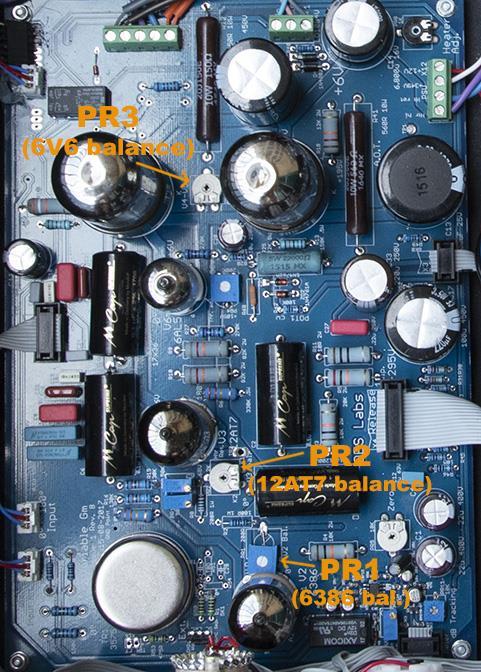
2 B. Calibration Procedure. 1. Warm-up time If cold, let the unit warm up for about mins. Confirm power supply, by checking the DC readings (please refer to the previous section). 2. Trimmers to adjust. The preset pots to adjust are the cathode balancing pots: PR1 (V1/V2 bal., 200R), PR2 (V3 bal., 2K2) and PR3 (100R, V4/V5 Bal.). They interact one with the other, so you must re-adjust until proper balance is achieved. Please refer to fig. 2 below to locate the preset pots on the boards. 2
3 3
 operation.")
4 3. Calibration Start with PR1 first, then PR2 and PR3. Set all the pots in center position, to start. Connect a dual channel oscilloscope to the XLR output of the channel to calibrate. CH1 Normal polarity, CH2 Inverted polarity, Scope set to ADD operation. If using Digital Storage type oscilloscope, set CH1-CH2 (difference) operation. Connect a 10-20kΩ resistor between pin 2 and 3, probes as follows: CH1 tip to resistor end connected to XLR output pin 2 (hot), clip to pin 1 (screen-gnd), CH2 tip to resistor end connected to XLR output pin 3 (cold), clip to pin 1 Ref. to fig. below. FIG. 3 Oscilloscope settings: Vertical (Y axis): 2 volts/division Horizontal (X axis): 5 msec./div. Coupling: DC, BW limited to 20MHz (if your scope has this feature). 4

. The tone burst may be found in the file cal.wav. Play it in loop.")
5 Connect your DAC balanced outputs (+4dB) to the Inputs of the Variable Gm. Now apply a Tone Burst (pulsed) signal. This should be a pure 10kHz sine wave with the burst on for 50 cycles, worth of 10kHz at an amplitude of +4dB. Burst low should be 150 cycles worth of 10kHz at an amplitude of -20dB. This gives a repeating waveform of 200 cycles worth of 10kHz sine wave with two different amplitudes in it. Your oscillator s output impedance should be low (50 Ω are ok, you can use your DAC s output). The tone burst may be found in the file cal.wav. Play it in loop. Set dual mono mode, both inputs and outputs knobs to about mid position, so that the system gain is about 5/6 db. Then advance the Threshold control for a 3/4dB of gain reduction. If the cathodes are unbalanced, your picture should look like the following: Fig. 4 Turn the Threshold control to out, then adjust the preset pots to achieve good cathode balance, common mode rejection, CV rejection (no thumping when limiting) and symmetrical audio signal. The following picture shows a satisfactory balance (threshold out): Fig. 5 5
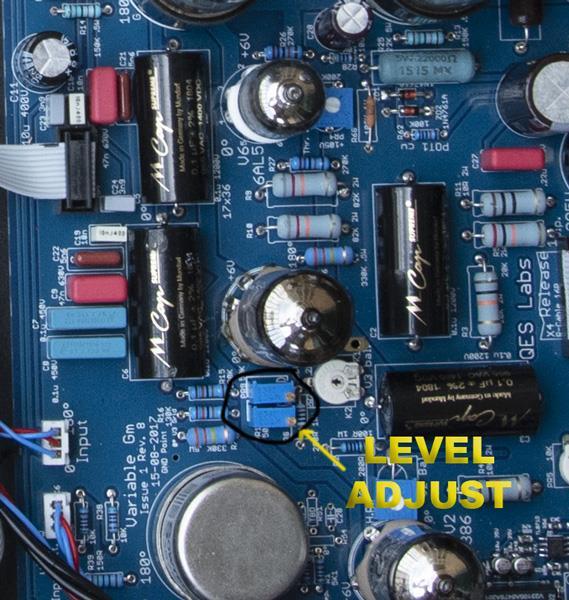
6 Advance the Threshold control to achieve about 3 4 db of Peak reduction, adjust the preset pots to achieve a stable image on the oscilloscope, so to null or level the tone bursts, no slant between the tone bursts, the adjustment is for a straight line on the center of the oscilloscope (you will see a shark-fin looking control voltage, as in fig. 10 : null it). Check for proper balance for any position of the Threshold knob. Refer to fig. 12 below, threshold set for 4dB GR. Fig Level matching between channels. Feed both the compressor Inputs with a pure sine wave, by using a Signal Generator from your DAW (Pro Tools, Logic, etc.), set the frequency to 1kHz, amplitude to -30 dbfs. Set both channels Input and Output controls to Max. position (fully clockwise), Threshold to out. Dual Mono mode. Now monitor the Output XLR (between pins 2 and 3) through a precision True RMS Volt Meter, symmetrically set PR9 and PR10 preset pots so that you can read exactly the same signal amplitude for both channels. (I.E. if you make one turn cw on PR9, do the same for PR10, if you need to turn ccw on PR9, do the same on PR10, etc.). Please refer to fig. 7 below to locate the pots on the board. 6
7 Fig. 7 7
WESTREX RA-1712 PHOTOGRAPHIC SOUND RECORD ELECTRONICS
 INTRODUCTION The RA-1712 solid state Record Electronics is an integrated system for recording photographic sound tracks on a Westrex photographic sound recorder. It accepts a 600Ω input signal level from
The University of Jordan Mechatronics Engineering Department Electronics Lab.( ) Experiment 1: Lab Equipment Familiarization
 Experiment 1: Lab Equipment Familiarization") The University of Jordan Mechatronics Engineering Department Electronics Lab.(0908322) Experiment 1: Lab Equipment Familiarization Objectives To be familiar with the main blocks of the oscilloscope and
The University of Jordan Mechatronics Engineering Department Electronics Lab.(0908322) Experiment 1: Lab Equipment Familiarization Objectives To be familiar with the main blocks of the oscilloscope and
Solid State Logic S O U N D V I S I O N
 Solid State Logic S O U N D V I S I O N SUPERANALOGUE X - R A C K Super-Analogue Outboard X-Rack Stereo Dynamics User s Guide This documentation package contains the User s Guide for your new X-Rack Stereo
IPR LA-3 KIT last update 15 march 06
 IPR LA-3 KIT last update 15 march 06 PART-2: Audio Circuitry CIRCUIT BOARD LAYOUT: Power and Ground Distribution Now that your power supply is functional, it s time to think about how that power will be
Introduction to Basic Laboratory Instruments
 Introduction to Contents: 1. Objectives... 2 2. Laboratory Safety... 2 3.... 2 4. Using a DC Power Supply... 2 5. Using a Function Generator... 3 5.1 Turn on the Instrument... 3 5.2 Setting Signal Type...
E-200D ALIGNMENT. See the end of the procedure for the location of the calibration points. EQUIPMENT REQUIRED
 E-200D ALIGNMENT NOTE: This is not an official B&K alignment procedure. This procedure was created by experimenting with an E-200D. However when this procedure is followed, the resulting calibration should
Exercise 1: AC Waveform Generator Familiarization
 Exercise 1: AC Waveform Generator Familiarization EXERCISE OBJECTIVE When you have completed this exercise, you will be able to operate an ac waveform generator by using equipment provided. You will verify
3 - Using the Telecoms-Trainer 101 to model equations
 Name: Class: 3 - Using the Telecoms-Trainer 101 to model equations Experiment 3 Using the Telecoms-Trainer 101 to model equations Preliminary discussion This may surprise you, but mathematics is an important
CLASS A DUAL TRANSFORMER COMPRESSOR OWNER S MANUAL
 LIMINATOR CLASS A DUAL TRANSFORMER COMPRESSOR OWNER S MANUAL TABLE OF CONTENTS SECTION PAGE INTRODUCTION 2 INSTALLATION 3 FRONT PANEL CONTROLS 4 OPERATION 5 SPECIFICATIONS 7 WARRANTY AND REGISTRATION 8-1
Introduction to basic laboratory instruments
 Introduction to basic laboratory instruments 1. OBJECTIVES... 2 2. LABORATORY SAFETY... 2 3. BASIC LABORATORY INSTRUMENTS... 2 4. USING A DC POWER SUPPLY... 2 5. USING A FUNCTION GENERATOR... 3 5.1 TURN
Sonoma State University Department of Engineering Science Spring 2017
 EE 110 Introduction to Engineering & Laboratory Experience Saeid Rahimi, Ph.D. Lab 4 Introduction to AC Measurements (I) AC signals, Function Generators and Oscilloscopes Function Generator (AC) Battery
the DON classics U76 (blue face - rev A) ASSEMBLY GUIDE REV: 1:04
 ASSEMBLY GUIDE REV: 1:04") the DON classics www.thedonclassics.com U76 (blue face - rev A) ASSEMBLY GUIDE REV: 1:04 QUICK ASSEMBLY GUIDE 9 STEPS TO COMPRESSOR HEAVEN! 1. 2. 3. 4. 5. 6. 7. 8. 9. Solder parts on PCB Wire pots Solder
the DON classics www.thedonclassics.com U76 (blue face - rev A) ASSEMBLY GUIDE REV: 1:04 QUICK ASSEMBLY GUIDE 9 STEPS TO COMPRESSOR HEAVEN! 1. 2. 3. 4. 5. 6. 7. 8. 9. Solder parts on PCB Wire pots Solder
University of Jordan School of Engineering Electrical Engineering Department. EE 204 Electrical Engineering Lab
 University of Jordan School of Engineering Electrical Engineering Department EE 204 Electrical Engineering Lab EXPERIMENT 1 MEASUREMENT DEVICES Prepared by: Prof. Mohammed Hawa EXPERIMENT 1 MEASUREMENT
Solid State Logic S O U N D V I S I O N
 Solid State Logic S O U N D V I S I O N SUPERANALOGUE X - R A C K Super-Analogue Outboard X-Rack E Series EQ User s Guide This documentation package contains the User s Guide for your new X-Rack E Series
ECE3204 D2015 Lab 1. See suggested breadboard configuration on following page!
 ECE3204 D2015 Lab 1 The Operational Amplifier: Inverting and Non-inverting Gain Configurations Gain-Bandwidth Product Relationship Frequency Response Limitation Transfer Function Measurement DC Errors
Sirindhorn International Institute of Technology Thammasat University at Rangsit
 Sirindhorn International Institute of Technology Thammasat University at Rangsit School of Information, Computer and Communication Technology COURSE : ECS 210 Basic Electrical Engineering Lab INSTRUCTOR
Overview. Features. Technical Data Sheet 1 / 6. Mixing Console MG20. MG20 is a versatile mixer suitable for a wide range of users and applications.
 Overview MG20 is a versatile mixer suitable for a wide range of users and applications. Rear Panel Features Input channels: 20 Line Inputs (12 mono, 4 stereo), 16 Mic Inputs with 48V phantom power and
TUBE-TECH LCA 2B compressor and limiter
 TUBE-TECH LCA 2B compressor and limiter DESCRIPTION: The TUBE-TECH LCA 2B is a two-channel unit with an independent compressor and limiter per channel. The unit is all tubebased (except for the power supply
Exercise 2: Demodulation (Quadrature Detector)
") Analog Communications Angle Modulation and Demodulation Exercise 2: Demodulation (Quadrature Detector) EXERCISE OBJECTIVE When you have completed this exercise, you will be able to explain demodulation
Analog Communications Angle Modulation and Demodulation Exercise 2: Demodulation (Quadrature Detector) EXERCISE OBJECTIVE When you have completed this exercise, you will be able to explain demodulation
Oscilloscope and Function Generators
 MEHRAN UNIVERSITY OF ENGINEERING AND TECHNOLOGY, JAMSHORO DEPARTMENT OF ELECTRONIC ENGINEERING ELECTRONIC WORKSHOP # 02 Oscilloscope and Function Generators Roll. No: Checked by: Date: Grade: Object: To
SERGE Ring Modulator 2017 (RING) for Eurorack
 for Eurorack") SERGE Ring Modulator 2017 (RING) for Eurorack The 2017 RING is an improved version of the late Serge Ring Modulator (R9), designed by Serge himself for Random*Source in 2017, more than 40 years after the
SERGE Ring Modulator 2017 (RING) for Eurorack The 2017 RING is an improved version of the late Serge Ring Modulator (R9), designed by Serge himself for Random*Source in 2017, more than 40 years after the
ENGR 1110: Introduction to Engineering Lab 7 Pulse Width Modulation (PWM)
") ENGR 1110: Introduction to Engineering Lab 7 Pulse Width Modulation (PWM) Supplies Needed Motor control board, Transmitter (with good batteries), Receiver Equipment Used Oscilloscope, Function Generator,
ENGR 1110: Introduction to Engineering Lab 7 Pulse Width Modulation (PWM) Supplies Needed Motor control board, Transmitter (with good batteries), Receiver Equipment Used Oscilloscope, Function Generator,
The Oscilloscope. Vision is the art of seeing things invisible. J. Swift ( ) OBJECTIVE To learn to operate a digital oscilloscope.
 OBJECTIVE To learn to operate a digital oscilloscope.") The Oscilloscope Vision is the art of seeing things invisible. J. Swift (1667-1745) OBJECTIVE To learn to operate a digital oscilloscope. THEORY The oscilloscope, or scope for short, is a device for drawing
The Oscilloscope Vision is the art of seeing things invisible. J. Swift (1667-1745) OBJECTIVE To learn to operate a digital oscilloscope. THEORY The oscilloscope, or scope for short, is a device for drawing
CHAPTER 6. Motor Driver
 CHAPTER 6 Motor Driver In this lab, we will construct the circuitry that your robot uses to drive its motors. However, before testing the motor circuit we will begin by making sure that you are able to
Laboratory Exercise 6 THE OSCILLOSCOPE
 Introduction Laboratory Exercise 6 THE OSCILLOSCOPE The aim of this exercise is to introduce you to the oscilloscope (often just called a scope), the most versatile and ubiquitous laboratory measuring
Experiment 1: Instrument Familiarization (8/28/06)
") Electrical Measurement Issues Experiment 1: Instrument Familiarization (8/28/06) Electrical measurements are only as meaningful as the quality of the measurement techniques and the instrumentation applied
Electrical Measurement Issues Experiment 1: Instrument Familiarization (8/28/06) Electrical measurements are only as meaningful as the quality of the measurement techniques and the instrumentation applied
MASSACHUSETTS INSTITUTE OF TECHNOLOGY
 Name: MASSACHUSETTS INSTITUTE OF TECHNOLOGY 6.091 Hands-On Introduction to EE Lab Skills Laboratory No. 1 Oscilloscopes, Multimeter, Function Generator IAP 2008 1 Objective In this laboratory, you will
ME 365 EXPERIMENT 1 FAMILIARIZATION WITH COMMONLY USED INSTRUMENTATION
 Objectives: ME 365 EXPERIMENT 1 FAMILIARIZATION WITH COMMONLY USED INSTRUMENTATION The primary goal of this laboratory is to study the operation and limitations of several commonly used pieces of instrumentation:
Experiment 1: Instrument Familiarization
 Electrical Measurement Issues Experiment 1: Instrument Familiarization Electrical measurements are only as meaningful as the quality of the measurement techniques and the instrumentation applied to the
2 : AC signals, the signal generator and the Oscilloscope
 2 : AC signals, the signal generator and the Oscilloscope Expected outcomes After conducting this practical, the student should be able to do the following Set up a signal generator to provide a specific
MASSACHUSETTS INSTITUTE OF TECHNOLOGY Hands-On Introduction to EE Lab Skills Laboratory No. 2 BJT, Op Amps IAP 2008
 Name MASSACHUSETTS INSTITUTE OF TECHNOLOGY 6.09 Hands-On Introduction to EE Lab Skills Laboratory No. BJT, Op Amps IAP 008 Objective In this laboratory, you will become familiar with a simple bipolar junction
Introduction to basic laboratory instruments
 BEE 233 Laboratory-1 Introduction to basic laboratory instruments 1. Objectives To learn safety procedures in the laboratory. To learn how to use basic laboratory instruments: power supply, function generator,
Solid State Logic S O U N D V I S I O N
 Solid State Logic S O U N D V I S I O N SUPERANALOGUE X - R A C K Super-Analogue Outboard X-Rack EQ User s Guide This documentation package contains the User s Guide for your new X-Rack EQ module. Depending
UNIVERSITY OF CALIFORNIA, SANTA BARBARA Department of Electrical and Computer Engineering. ECE 2A & 2B Laboratory Equipment Information
 UNIVERSITY OF CALIFORNIA, SANTA BARBARA Department of Electrical and Computer Engineering ECE 2A & 2B Laboratory Equipment Information Table of Contents Digital Multi-Meter (DMM)... 1 Features... 1 Using
Q106A Oscillator. Aug The Q106A Oscillator module is a combination of the Q106 Oscillator and the Q141 Aid module, all on a single panel.
 Aug 2017 The Q106A Oscillator module is a combination of the Q106 Oscillator and the Q141 Aid module, all on a single panel. The Q106A Oscillator is the foundation of any synthesizer providing the basic
LAB 7: THE OSCILLOSCOPE
 LAB 7: THE OSCILLOSCOPE Equipment List: Dual Trace Oscilloscope HP function generator HP-DMM 2 BNC-to-BNC 1 cables (one long, one short) 1 BNC-to-banana 1 BNC-probe Hand-held DMM (freq mode) Purpose: To
LAB I. INTRODUCTION TO LAB EQUIPMENT
 1. OBJECTIVE LAB I. INTRODUCTION TO LAB EQUIPMENT In this lab you will learn how to properly operate the oscilloscope Agilent MSO6032A, the Keithley Source Measure Unit (SMU) 2430, the function generator
Getting Started. MSO/DPO Series Oscilloscopes. Basic Concepts
 Getting Started MSO/DPO Series Oscilloscopes Basic Concepts 001-1523-00 Getting Started 1.1 Getting Started What is an oscilloscope? An oscilloscope is a device that draws a graph of an electrical signal.
StudioLive MIXER INPUTS.
 StudioLive 24.4.2 Architect & Engineering Specifications 1. GENERAL CONFIGURATION. The mixer shall be a digital mixer and shall accommodate 24 line and/or 24 microphone signals, channels 1 24; and shall
Cornerstone Electronics Technology and Robotics Week 21 Electricity & Electronics Section 10.5, Oscilloscope
 Cornerstone Electronics Technology and Robotics Week 21 Electricity & Electronics Section 10.5, Oscilloscope Field trip to Deerhaven Generation Plant: Administration: o Prayer o Turn in quiz Electricity
Piezo Driver MTAD4002
 Piezo Driver MTAD002 Instruction Manual Contents. Overview 2 2. List of contents 2 3. Specifications 2~3. Operation 3~. Signal Generation Software ~3. Precautions 3 Published on th Sept 20 Overview Piezo
FMR622S DUAL NARROW BAND SLIDING DE-EMPHASIS DEMODULATOR INSTRUCTION BOOK IB
 FMR622S DUAL NARROW BAND SLIDING DE-EMPHASIS DEMODULATOR INSTRUCTION BOOK IB 1222-22 TABLE OF CONTENTS SECTION 1.0 INTRODUCTION 2.0 INSTALLATION & OPERATING INSTRUCTIONS 3.0 SPECIFICATIONS 4.0 FUNCTIONAL
Lab 9: Operational amplifiers II (version 1.5)
") Lab 9: Operational amplifiers II (version 1.5) WARNING: Use electrical test equipment with care! Always double-check connections before applying power. Look for short circuits, which can quickly destroy
Lab 9: Operational amplifiers II (version 1.5) WARNING: Use electrical test equipment with care! Always double-check connections before applying power. Look for short circuits, which can quickly destroy
Dev Bhoomi Institute Of Technology Department of Electronics and Communication Engineering PRACTICAL INSTRUCTION SHEET
 Dev Bhoomi Institute Of Technology Department of Electronics and Communication Engineering PRACTICAL INSTRUCTION SHEET LABORATORY MANUAL EXPERIMENT NO. ISSUE NO. : ISSUE DATE: REV. NO. : REV. DATE : PAGE:
Q107/Q107A State Variable Filter
 Apr 28, 2017 The Q107 is dual-wide, full-featured State Variable filter. The Q107A is a single-wide version without the Notch output and input mixer attenuator. These two models share the same circuit
P a g e 1 ST985. TDR Cable Analyzer Instruction Manual. Analog Arts Inc.
 P a g e 1 ST985 TDR Cable Analyzer Instruction Manual Analog Arts Inc. www.analogarts.com P a g e 2 Contents Software Installation... 4 Specifications... 4 Handling Precautions... 4 Operation Instruction...
APPENDIX D DISCUSSION OF ELECTRONIC INSTRUMENTS
 APPENDIX D DISCUSSION OF ELECTRONIC INSTRUMENTS DC POWER SUPPLIES We will discuss these instruments one at a time, starting with the DC power supply. The simplest DC power supplies are batteries which
EECE208 INTRO To ELECTRICAL ENG LAB. LAB 2. Instrumentation
 EECE208 INTRO To ELECTRICAL ENG LAB Dr. Charles Kim LAB 2. Instrumentation Objectives A brief description of the equipment (Oscilloscope, Function Generator, Power Supply, and Digital Multimeter) and its
3 T856/857 Initial Tuning & Adjustment
 M850-00 T856/857 Initial Tuning & Adjustment C3.1 3 T856/857 Initial Tuning & Adjustment The following section describes the full tuning and adjustment procedure and provides information on: channel programming
Integrators, differentiators, and simple filters
 BEE 233 Laboratory-4 Integrators, differentiators, and simple filters 1. Objectives Analyze and measure characteristics of circuits built with opamps. Design and test circuits with opamps. Plot gain vs.
ECE 203 LAB 6: INVERTED PENDULUM
 Version 1.1 1 of 15 BEFORE YOU BEGIN EXPECTED KNOWLEDGE Basic Circuit Analysis EQUIPMENT AFG Oscilloscope Programmable Power Supply MATERIALS Three 741 Opamps TIP41 NPN power transistor TIP42 PNP power
Exp. #2-6 : Measurement of the Characteristics of,, and Circuits by Using an Oscilloscope
 PAGE 1/14 Exp. #2-6 : Measurement of the Characteristics of,, and Circuits by Using an Oscilloscope Student ID Major Name Team No. Experiment Lecturer Student's Mentioned Items Experiment Class Date Submission
PXIe Contents. Required Software CALIBRATION PROCEDURE
 CALIBRATION PROCEDURE PXIe-5160 This document contains the verification and adjustment procedures for the PXIe-5160. Refer to ni.com/calibration for more information about calibration solutions. Contents
Physics 310 Lab 4 Transformers, Diodes, & Power Supplies
 Physics 310 Lab 4 Transformers, Diodes, & Power Supplies Equipment: O scope, W02G Bridge Rectifier, 110 6.3V transformer, four 1N4004 diodes, 1k, 10µF, 100µF, 1N5231 Zeener diode, ½ - Watt 100 Ω, 270Ω,
Type Ordering Code Package TDA Q67000-A5168 P-DIP-18-5
 Video Modulator for FM-Audio TDA 5666-5 Preliminary Data Bipolar IC Features FM-audio modulator Sync level clamping of video input signal Controlling of peak white value Continuous adjustment of modulation
Experiment 5 The Oscilloscope
 Experiment 5 The Oscilloscope Vision is the art of seeing things invisible. J. Swift (1667-1745) OBJECTIVE To learn to operate a cathode ray oscilloscope. THEORY The oscilloscope, or scope for short, is
ECE4902 C Lab 7
 ECE902 C2012 - Lab MOSFET Differential Amplifier Resistive Load Active Load PURPOSE: The primary purpose of this lab is to measure the performance of the differential amplifier. This is an important topology
10: AMPLIFIERS. Circuit Connections in the Laboratory. Op-Amp. I. Introduction
 10: AMPLIFIERS Circuit Connections in the Laboratory From now on you will construct electrical circuits and test them. The usual way of constructing circuits would be to solder each electrical connection
VC528 ST2+ RV1 CMRR Trimmer
 VC528 ST2+ RV1 CMRR Trimmer Now that you have completed the build of your VC528 ST2+ module, we need to calibrate and adjust the RV1 trimmer potentiometer for optimum CMRR. This must be done before you
ECE Lab #4 OpAmp Circuits with Negative Feedback and Positive Feedback
 ECE 214 Lab #4 OpAmp Circuits with Negative Feedback and Positive Feedback 20 February 2018 Introduction: The TL082 Operational Amplifier (OpAmp) and the Texas Instruments Analog System Lab Kit Pro evaluation
EXPERIMENT NUMBER 2 BASIC OSCILLOSCOPE OPERATIONS
 1 EXPERIMENT NUMBER 2 BASIC OSCILLOSCOPE OPERATIONS The oscilloscope is the most versatile and most important tool in this lab and is probably the best tool an electrical engineer uses. This outline guides
AP034-OM-E Rev D ISSUED: January 2000 ²
 3HUIRUPDQFH9HULILFDWLRQ 3HUIRUPDQFH9HULILFDWLRQ This procedure can be used to verify the warranted characteristics of the AP034 Active Differential Probe. The recommended calibration interval for the model
EE 368 Electronics Lab. Experiment 10 Operational Amplifier Applications (2)
") EE 368 Electronics Lab Experiment 10 Operational Amplifier Applications (2) 1 Experiment 10 Operational Amplifier Applications (2) Objectives To gain experience with Operational Amplifier (Op-Amp). To
EE 368 Electronics Lab Experiment 10 Operational Amplifier Applications (2) 1 Experiment 10 Operational Amplifier Applications (2) Objectives To gain experience with Operational Amplifier (Op-Amp). To
Q106 Oscillator. Controls and Connectors. Jun 2014
 The Q106 Oscillator is the foundation of any synthesizer providing the basic waveforms used to construct sounds. With a total range of.05hz to 20kHz+, the Q106 operates as a powerful audio oscillator and
MGM 3000X Q67000-A5179 P-DSO-20-1 (SMD) MGM 3000X Q67006-A5179 P-DSO-20-1 Tape & Reel (SMD)
 MGM 3000X Q67006-A5179 P-DSO-20-1 Tape & Reel (SMD)") Video Modulator for FM/AM-Audio MGM 3000X Bipolar IC Features FM- and AM-audio modulator Audio carrier output for suppression of harmonics Sync level clamping of video input signal Controlling of peak
Video Modulator for FM/AM-Audio MGM 3000X Bipolar IC Features FM- and AM-audio modulator Audio carrier output for suppression of harmonics Sync level clamping of video input signal Controlling of peak
Sept 13 Pre-lab due Sept 12; Lab memo due Sept 19 at the START of lab time, 1:10pm
 Sept 13 Pre-lab due Sept 12; Lab memo due Sept 19 at the START of lab time, 1:10pm EGR 220: Engineering Circuit Theory Lab 1: Introduction to Laboratory Equipment Pre-lab Read through the entire lab handout
Summit Audio Model DCL-200 Dual Compressor-Limiter Operating Manual
 Summit Audio Model DCL-200 Dual Compressor-Limiter Operating Manual IMPORTANT!: CAREFULLY READ THE ENTIRE INSTRUCTION MANUAL BEFORE HOOKUP OR OPERATION OF THE DCL-200. WARNING!: HIGH VOLTAGE. THIS UNIT
EXPERIMENT 1 PRELIMINARY MATERIAL
 EXPERIMENT 1 PRELIMINARY MATERIAL BREADBOARD A solderless breadboard, like the basic model in Figure 1, consists of a series of square holes, and those columns of holes are connected to each other via
EECE208 INTRO To ELECTRICAL ENG LAB. LAB 2. Instrumentation
 EECE208 INTRO To ELECTRICAL ENG LAB Dr. Charles Kim LAB 2. Instrumentation Objectives A brief description of the equipment (Oscilloscope, Function Generator, Power Supply, and Digital Multimeter) and its
LABORATORY 4. Palomar College ENGR210 Spring 2017 ASSIGNED: 3/21/17
 LABORATORY 4 ASSIGNED: 3/21/17 OBJECTIVE: The purpose of this lab is to evaluate the transient and steady-state circuit response of first order and second order circuits. MINIMUM EQUIPMENT LIST: You will
POLYTECHNIC UNIVERSITY Electrical Engineering Department. EE SOPHOMORE LABORATORY Experiment 3 The Oscilloscope
 POLYTECHNIC UNIVERSITY Electrical Engineering Department EE SOPHOMORE LABORATORY Experiment 3 The Oscilloscope Modified for Physics 18, Brooklyn College I. Overview of the Experiment The main objective
ALM473 DUAL MONO \ STEREO AUDIO LEVEL MASTER OPERATION MANUAL IB
 ALM473 DUAL MONO \ STEREO AUDIO LEVEL MASTER OPERATION MANUAL IB6408-01 TABLE OF CONTENTS GENERAL DESCRIPTION 2 INSTALLATION 2,3,4 CONNECTION AND SETUP 4,5,6,7 FUNCTIONAL DESCRIPTION 8,9 MAINTENANCE 9
SDM3045X Digital Multimeter. DataSheet
 SDM3045X Digital Multimeter DataSheet-2016.06 User-friendly Design Product Overview SDM3045X is a 4½ digit digital (60000 count) multimeter incorporating a dual-display and is especially well suited for
Analog Arts SL987 SL957 SL937 SL917 Product Specifications [1]
![Analog Arts SL987 SL957 SL937 SL917 Product Specifications [1]](/thumbs/95/126095980.jpg "Analog Arts SL987 SL957 SL937 SL917 Product Specifications [1]") www.analogarts.com Analog Arts SL987 SL957 SL937 SL917 Product Specifications [1] 1. These models include: an oscilloscope, a spectrum analyzer, a data recorder, a frequency & phase meter, an arbitrary
www.analogarts.com Analog Arts SL987 SL957 SL937 SL917 Product Specifications [1] 1. These models include: an oscilloscope, a spectrum analyzer, a data recorder, a frequency & phase meter, an arbitrary
NTE7132 Integrated Circuit Horizontal and Vertical Deflection Controller for VGA/XGA and Multi Frequency Monitors
 NTE7132 Integrated Circuit Horizontal and Vertical Deflection Controller for VGA/XGA and Multi Frequency Monitors Description: The NTE7132 is an integrated circuit in a 20 Lead DIP type package. This device
EE431 Lab 1 Operational Amplifiers
 Feb. 10, 2015 Report all measured data and show all calculations Introduction The purpose of this laboratory exercise is for the student to gain experience with measuring and observing the effects of common
ECE 53A: Fundamentals of Electrical Engineering I
 ECE 53A: Fundamentals of Electrical Engineering I Laboratory Assignment #1: Instrument Operation, Basic Resistor Measurements and Kirchhoff s Laws Fall 2007 General Guidelines: - Record data and observations
Test No. 1. Introduction to Scope Measurements. Report History. University of Applied Sciences Hamburg. Last chance!! EEL2 No 1
 University of Applied Sciences Hamburg Group No : DEPARTMENT OF INFORMATION ENGINEERING Laboratory for Instrumentation and Measurement L: in charge of the report Test No. Date: Assistant A2: Professor:
Name EET 1131 Lab #2 Oscilloscope and Multisim
 Name EET 1131 Lab #2 Oscilloscope and Multisim Section 1. Oscilloscope Introduction Equipment and Components Safety glasses Logic probe ETS-7000 Digital-Analog Training System Fluke 45 Digital Multimeter
Analog Arts SF990 SF880 SF830 Product Specifications
 1 www.analogarts.com Analog Arts SF990 SF880 SF830 Product Specifications Analog Arts reserves the right to change, modify, add or delete portions of any one of its specifications at any time, without
Experiment A8 Electronics III Procedure
 Experiment A8 Electronics III Procedure Deliverables: checked lab notebook, plots Overview Electronics have come a long way in the last century. Using modern fabrication techniques, engineers can now print
Lab Reference Manual. ECEN 326 Electronic Circuits. Texas A&M University Department of Electrical and Computer Engineering
 Lab Reference Manual ECEN 326 Electronic Circuits Texas A&M University Department of Electrical and Computer Engineering Contents 1. Circuit Analysis in PSpice 3 1.1 Transient and DC Analysis 3 1.2 Measuring
EE 3305 Lab I Revised July 18, 2003
 Operational Amplifiers Operational amplifiers are high-gain amplifiers with a similar general description typified by the most famous example, the LM741. The LM741 is used for many amplifier varieties
RC Filters and Basic Timer Functionality
 RC-1 Learning Objectives: RC Filters and Basic Timer Functionality The student who successfully completes this lab will be able to: Build circuits using passive components (resistors and capacitors) from
LM4562 Dual High Performance, High Fidelity Audio Operational Amplifier
 Dual High Performance, High Fidelity Audio Operational Amplifier General Description The is part of the ultra-low distortion, low noise, high slew rate operational amplifier series optimized and fully
Basic operational amplifier circuits In this lab exercise, we look at a variety of op-amp circuits. Note that this is a two-period lab.
 Basic operational amplifier circuits In this lab exercise, we look at a variety of op-amp circuits. Note that this is a two-period lab. Prior to Lab 1. If it has been awhile since you last used the lab
Single Supply, Rail to Rail Low Power FET-Input Op Amp AD820
 a FEATURES True Single Supply Operation Output Swings Rail-to-Rail Input Voltage Range Extends Below Ground Single Supply Capability from V to V Dual Supply Capability from. V to 8 V Excellent Load Drive
Experiment One: Generating Frequency Modulation (FM) Using Voltage Controlled Oscillator (VCO)
 Using Voltage Controlled Oscillator (VCO)") Experiment One: Generating Frequency Modulation (FM) Using Voltage Controlled Oscillator (VCO) Modified from original TIMS Manual experiment by Mr. Faisel Tubbal. Objectives 1) Learn about VCO and how
Experiment One: Generating Frequency Modulation (FM) Using Voltage Controlled Oscillator (VCO) Modified from original TIMS Manual experiment by Mr. Faisel Tubbal. Objectives 1) Learn about VCO and how
evolution wireless G4 ew 500 BOOM G4 Pro Camera Plug-on Transmitter set
 1/6 The professional s choice for broadcast quality sound Providing the highest flexibility for your video sound and field recording applications. A robust wireless microphone system that offers ultimate
 1 of 6 03/12/2012 14:56 2012-12-03 HAMEG > Products > Accessories > Probes http://www.hameg.com/186.0.html P R O B E S H Z 5 6-2 * AC/ DC Current Clamps This AC/DC Current Probe is used to measure currents
9 Feedback and Control
 9 Feedback and Control Due date: Tuesday, October 20 (midnight) Reading: none An important application of analog electronics, particularly in physics research, is the servomechanical control system. Here
R*S Stereo Mixer V1.3
 R*S Stereo Mixer V1.3 The Random*Source Equal Power Stereo-Mixer is a voltage controlled stereo mixer / panner / VCA based on 4 high-end THAT2180 blackmer VCAs, designed to emulate the behavior of Serge
Notes on Experiment #1
 Notes on Experiment #1 Bring graph paper (cm cm is best) From this week on, be sure to print a copy of each experiment and bring it with you to lab. There will not be any experiment copies available in
Lab 0: Introduction to basic laboratory instruments. Revised by Dan Hoang & Tai-Chang Chen 03/30/2009
 Lab 0: Introduction to basic laboratory instruments Revised by Dan Hoang & Tai-Chang Chen 03/30/2009 1. Objectives 1. To learn safety procedures in the laboratory. 2. To learn how to use basic laboratory
Device Interconnection
 Device Interconnection An important, if less than glamorous, aspect of audio signal handling is the connection of one device to another. Of course, a primary concern is the matching of signal levels and
B MTS Systems Corp., Model Function Generator
 0189 115585-02 B MTS Systems Corp., 1988 Model 410.81 Function Generator Table of Contents Section 1 Introduction 1.1 Functional Description 1-1 1.2 Specifications 1-2 Section 2 Operation 2.1 Control Mode
OBSOLETE. Low Cost Quad Voltage Controlled Amplifier SSM2164 REV. 0
 a FEATURES Four High Performance VCAs in a Single Package.2% THD No External Trimming 12 db Gain Range.7 db Gain Matching (Unity Gain) Class A or AB Operation APPLICATIONS Remote, Automatic, or Computer
University of Utah Electrical & Computer Engineering Department ECE 2210/2200 Lab 4 Oscilloscope
 University of Utah Electrical & Computer Engineering Department ECE 2210/2200 Lab 4 Oscilloscope Objectives 1 Introduce the Oscilloscope and learn some uses. 2 Observe Audio signals. 3 Introduce the Signal
audionet amp II G2 Owner's Manual Mono - Amplifier
 audionet amp II G2 Mono - Amplifier Owner's Manual Owner's manual The Audionet-Team would like to congratulate you to purchasing the Audionet AMP II G2! Your Audionet AMP II G2 is designed for absolutely
Resonant and Nonresonant Lines. Input Impedance of a Line as a Function of Electrical Length
 Exercise 3-3 The Smith Chart, Resonant Lines, EXERCISE OBJECTIVES Upon completion of this exercise, you will know how the input impedance of a mismatched line varies as a function of the electrical length