TSEK02: Radio Electronics Lecture 8: RX Nonlinearity Issues, Demodulation. Ted Johansson, EKS, ISY
|
|
|
- Tamsin Higgins
- 5 years ago
- Views:
Transcription
1 TSEK02: Radio Electronics Lecture 8: RX Nonlinearity Issues, Demodulation Ted Johansson, EKS, ISY
2 2 RX Nonlinearity Issues, Demodulation RX nonlinearities (parts of 2.2) System Nonlinearity Sensitivity and Dynamic Range The Quadrature Demodulator Bit and Symbol Error Rate and E b /N 0
3 3 RX Nonlinearity Issues Nonlinearities that dominates at the TX: harmonic distortion, gain compression, intermodulation,... At RX side, similar and some additional effects are also relevant: desensitization, cross modulation.
 y(t)= α 1 V in + α 2 V 2 in + α 3 V3")

4 From previous lecture Harmonic distortion 4 Consider a nonlinear system x(t) y(t)= α 1 V in + α 2 V 2 in + α 3 V3 in +... Let us apply a single-tone (A cosωt) to the input and calculate the output: DC Fundamental Second Third Harmonic Harmonic
5 From previous lecture Gain Compression (1dB, P 1dB ) 5 Eventually at large enough signal levels, output power does not follow the input power The P-1dB point correlates well to loss of linear behavior, getting out-of-spec in standards (EVM, ACPR, etc.) so for linear applications, operation beyond this point is useless.
6 Intermodulation From previous lecture 6 Fundamental components: Intermodulation products:

7 From previous lecture 7 Intermodulation IM3 products do not interfere with main tones, so why should we be worried? They interfere with adjacent channels! Intermodulation products are troublesome both in the transmitter and in the receiver.
8 From previous lecture Intermodulation Intercept Point For a given input level (well below P1dB), the IIP3 can be calculated by halving the difference between the output fundamental and IM levels and adding the result to the input level, where all values are expressed as logarithmic quantities. 8
 At the input of the receiver, a strong interference")
9 9 Desensitization (p. 19) At the input of the receiver, a strong interference may exist close to the desired signal
10 10 Desensitization: related to gain compression The small signal is superimposed on the large signal (time domain). If the large signal compresses the amplifiers, it will also affect the small signal.
11 Desensitization 11 Assume x(t) = A1 cos ω1t + A2 cos ω2t where A1 is the desired component at ω1, A2 the interferer at ω2. When in compression For A1 << A2: If α 1 α 3 < 0, the receiver may not sufficiently amplify the small signal A 1 due to the strong interferer A 2 Also called "blocker". Creates problems when trying to keep the number of filters low.
12 Cross-Modulation (2.2.3) 12 Any amplitude variation (AM) of the strong interferer A2 will also appear on the amplitude of the signal A1 at the desired frequency and distort the signal. Interferer: results in:
13 13 Cross-Modulation Cross modulation commonly arises in amplifiers that must simultaneously process many independent signal channels. Examples include cable television transmitters and systems employing OFDM such as WLAN and 4G LTE.
14 Band Filter 14 In order to limit the input power to the receiver, a band pass filter covering the RX frequency band of interest is inserted after the antenna. Since BW is large compared to center frequency, a moderate Q-factor is enough for the filter. Due to its loss, it however adds noise to the system. It is always desirable to design more linear low-noise amplifiers and remove this filter.
15 15 RX Nonlinearity Issues, Demodulation RX nonlinearities System Nonlinearity Sensitivity and Dynamic Range The Quadrature Demodulator Bit and Symbol Error Rate and E b /N 0
16 From previous lecture 16 Intercept point of Cascaded Stages (Le5) Nonlinearity of each stage contributes to the overall system linearity
17 17 Intercept Point of Cascaded Stages In order to calculate the total intercept point: 1. Slide all intercept points of all stages to one side of the chain (input or output) Note that IIP3 and OIP3 are related through gain 2. Calculate the total intercept point at that point like a parallel resistor calculation G 1 (OIP3) 1 G 2 (OIP3) = + (OIP3) tot (OIP3) 2 G 2 (OIP3) 1
18 18 Receiver Linearity and Noise: Summary For a receiver we would like to have a high IIP3: Less gain at earlier stages and more linearity at later stages. We also need to decrease the total noise: More gain and less noise at earlier stages. Conflict! Always do calculations and see how gain, noise and linearity of each stage affect the overall RX performance.
19 19 RX Nonlinearity Issues, Demodulation RX nonlinearities System Nonlinearity Sensitivity and Dynamic Range (2.4) The Quadrature Demodulator Bit and Symbol Error Rate and E b /N 0
20 Thermal Noise 20 Due to random movements of electrons, a resistor (R) at temperature T [K] generates noise. Average Power of this noise across a matched load (R L =R) measured over B Hz at any frequency is given by ktb * B Noise power is: Only determined by T Independent of value of R Independent of frequency At temperature T [K] At temperature T=0[K] * T [K] * Boltzmann constant k = 1.38 x [J/K]
21 Sensitivity (2.4.1) 21 The sensitivity is defined as the minimum signal level that a receiver can detect with acceptable quality. Psig = input signal power PRS = noise power from the source resistance Total signal power Overall signal power is distributed over bandwidth B
22 Sensitivity 22 Going to db and dbm for a minimum input signal gives the sensitivity: Total integrated noise of the system ("noise floor") (receiver matched to the antenna)
23 23
24 24
25 Dynamic Range (2.4.2) 25 Range of signals which could be processed by the receiver is limited: Lower end: Signals should be strong enough to provide the desired SNR. Higher end: Signals should not push the receiver into nonlinear operation. Dynamic Range: Maximum tolerable desired signal power / minimum tolerable desired signal power. Expressed in [db]. Noise Floor
26 Spurious-Free Dynamic Range (SFDR) 26 Lower end: Equal to sensitivity. Higher end: Maximum input level in a two-tone test for which the third-order IM products do not exceed the integrated noise of the receiver.
27 27 Spurious-Free Dynamic Range (SFDR) Pout (dbm) Pmin = Noise Floor + SNR min Pmax = (2IIP3 + Noise Floor)/3 Min SNR Noise power level (noise floor) Pmax Pmin (sensitivity) Pin (dbm)
28 28 Spurious-Free Dynamic Range (SFDR) The SFDR represents the maximum relative level of interferers that a receiver can tolerate while producing an acceptable signal quality from a small input level.
29 29 Automatic Gain Control (AGC) At some point along the receiver chain, circuits should operate with fixed signal levels (or range of levels). An example is an Analog to Digital Converter which operates with a fixed input voltage. As the input signal level varies, gain of the receiver should also be variable to maintain the fixed voltage at the input of an ADC. This is achieved by an AGC, a closed-loop regulating circuit, providing a controlled output signal amplitude, despite variations in the input signal.
30 30 Automatic Gain Control (AGC)
31 31 RX Nonlinearity Issues, Demodulation RX nonlinearities System Nonlinearity Sensitivity and Dynamic Range The Quadrature Demodulator Bit and Symbol Error Rate and E b /N 0
32 32 Amplitude and Phase Information Remember our receiver-detector arrangement: Incoming Signal Received Signal Detected information detector Depending on the modulation format, the received signal may contain information on both amplitude and phase The detector should be able to detect both amplitude and phase
33 33 Amplitude Detection Amplitude detection, often referred to as envelop detection, is relatively simple and may be performed: incoherently (we only need to know the carrier frequency) coherently (the detector must also include the phase of the signal)
34 Incoherent Envelop Detection By passing the modulated signal through a nonlinear transfer function (e.g. a diode), the envelop of the signal may be detected. Condition for successful detection: the signal contains a component at the carrier frequency Advantage : simplicity Disadvantage : limited application and higher error V in = [A(t) + k] * cos ω c t Vout = V 2 in = [A 2 (t) + k 2 ]/2 + ka(t) + [ ]*cos 2ω c t Extracted by a filter 34 A diode has a square-like characteristic Parallel RC acts as LPF

35 Coherent Envelope Detection 35 Mixing the signal with a reference signal at the carrier frequency. The reference signal may be generated by a local oscillator or extracted from the signal itself. Advantage: superior accuracy and wider application Disadvantage: complex V in = A(t) cos ω c t Vout = V in *cos (ω c t+φ)= ½A (t) cos(φ) + [...]*cos(2w c t+φ) Extracted by a filter
36 36 Example of an envelope detector (4.4) On-off keying (OOK) modulation is a special case of ASK where the carrier amplitude is switched between zero and maximum. An LNA followed by an envelope detector can recover the binary data.
37 37 Phase Detection Phase detection is however more complex. We wish to detect phase of a signal with an envelop detector!
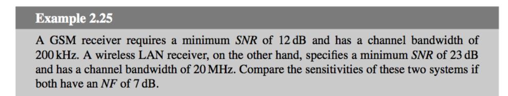
38 38 Quadrature Demodulator A signal with variable amplitude and phase may be expressed as s(t)= A(t) cos [ω c t+ φ(t)]. When expanded: s(t)= A(t) cos [ω c t+ φ(t)] = A(t) cos ω c t cos φ(t) A(t) sin ω c t sin φ(t) = A(t) cos φ(t) cos ω c t A(t) sin φ(t) sin ω c t = I(t) cos ω c t + Q(t) sin ω c t We call these the In-phase and Quadrature components of the signal.
![Quadrature Demodulator 39 s(t)= A(t) cos [ω c t+ φ(t)] = I(t) cos ω c t + Q(t) sin ω c t cos ω c t sin ω c t I(t)/2 These two signals may be detected by](/docs-images/95/125841651/images/39-2.jpg "amplitude detector Q(t)/2 Once I(t) and Q(t) are detected, the amplitude and phase of the signal can be recalculated: A(t) = I 2 (t)+q 2 (t) φ(t) = tan 1 Q(t)")
39 Quadrature Demodulator 39 s(t)= A(t) cos [ω c t+ φ(t)] = I(t) cos ω c t + Q(t) sin ω c t cos ω c t sin ω c t I(t)/2 These two signals may be detected by amplitude detector Q(t)/2 Once I(t) and Q(t) are detected, the amplitude and phase of the signal can be recalculated: A(t) = I 2 (t)+q 2 (t) φ(t) = tan 1 Q(t) I (t)

40 40 Putting everything together... A quadrature-mixer can be placed after the frequency of the signal is reduced to IF and channel selection is performed. I and Q signals are baseband, so ω in = ω LO1 + ω LO2. Channel selection may be more effectively performed on I & Q. Images may have to be taken care of. This filter is inserted to remove strong interferers
41 41 "Real" heterodyne "sampling-if" (TDD) More advanced variants include sampling the signal at IF and then doing the rest digitally.
42 42 RX Nonlinearity Issues, Demodulation RX nonlinearities System Nonlinearity Sensitivity and Dynamic Range The Quadrature Demodulator Bit and Symbol Error Rate and E b /N 0
43 43 Motivation Different modulation formats have different number of symbols and occupy different bandwidth. To be fair when comparing performance of different modulation formats, we would like to base our judgment on: Bit Error Rate (instead of symbol error rate), Bit Energy (instead of signal energy), Noise spectral density (instead of noise power).
44 44 Bit error vs. Symbol Error A symbol consists of k bits Symbol error is related to the bit error by Bit Error = Symbol Error / k = Symbol Error / log2m where M is the number of symbols.
45 45 Bit Energy (E b ) vs. Signal Power A signal consists of bits. Signal power is energy. Average Signal Power = bit energy (Eb) * number of bits per second (bitrate, Rb) = Eb * Rb Bit energy (Eb) = the power in one bit (P) multiplied by the bit time tb
46 46 Noise spectral density (N 0 ) vs. noise power Noise power density is constant over frequency, so Noise power = N0 * B where N0 is the noise spectral density (kt) and B is the bandwidth.
47 E b /N 0 vs. Signal-to-Noise Ratio 47 A better measure of signal-to-noise ratio for digital data is the ratio of energy per bit transmitted (Eb) to the noise power density (N0). SNR (a quantity which can be measured) is related to E b /N 0 (an artificial quantity used in comparisons) by is the spectral density (bitrate / bandwidth).
48 BER vs. E b /N 0 for different modulations 48

49 49
.")
50 TSEK38: Radio Frequency Transceiver Design VT Advanced continuation of TSEK02 Radio Electronics. Learn design methods and techniques for RF frontend design at the system level. Work with professional design tools (Keysight ADS). Lectures, lab, project work (no exam).
51 TSEK03: Radio Frequency Integrated Circuits (2019 HT1) 51 Learn the details of the RF blocks used in CMOS digital transceivers: Low-noise amplifiers (LNAs), Mixers, Oscillators, Frequency synthesizers (PLLs), Power amplifiers (PAs). Analysis on schematic level, calculation of circuit parameters. Labs: circuit simulations in cadence, LNA measurements in lab. Lectures, tutorials, lab, exam.
52
TSEK02: Radio Electronics Lecture 8: RX Nonlinearity Issues, Demodulation. Ted Johansson, EKS, ISY
 TSEK02: Radio Electronics Lecture 8: RX Nonlinearity Issues, Demodulation Ted Johansson, EKS, ISY RX Nonlinearity Issues: 2.2, 2.4 Demodulation: not in the book 2 RX nonlinearities System Nonlinearity
TSEK38 Radio Frequency Transceiver Design: Project work B
 TSEK38 Project Work: Task specification A 1(15) TSEK38 Radio Frequency Transceiver Design: Project work B Course home page: Course responsible: http://www.isy.liu.se/en/edu/kurs/tsek38/ Ted Johansson (ted.johansson@liu.se)
TSEK38: Radio Frequency Transceiver Design Lecture 6: Receiver Synthesis (I)
") TSEK38: Radio Frequency Transceiver Design Lecture 6: Receiver Synthesis (I) Ted Johansson, ISY ted.johansson@liu.se Systematic Receiver Synthesis (1) 4.1 Introduction 4. Sensitivity, Noise Figure Receiver
TSEK38: Radio Frequency Transceiver Design Lecture 6: Receiver Synthesis (I) Ted Johansson, ISY ted.johansson@liu.se Systematic Receiver Synthesis (1) 4.1 Introduction 4. Sensitivity, Noise Figure Receiver
ADI 2006 RF Seminar. Chapter II RF/IF Components and Specifications for Receivers
 ADI 2006 RF Seminar Chapter II RF/IF Components and Specifications for Receivers 1 RF/IF Components and Specifications for Receivers Fixed Gain and Variable Gain Amplifiers IQ Demodulators Analog-to-Digital
TSEK38: Radio Frequency Transceiver Design Lecture 3: Superheterodyne TRX design
 TSEK38: Radio Frequency Transceiver Design Lecture 3: Superheterodyne TRX design Ted Johansson, ISY ted.johansson@liu.se 2 Outline of lecture 3 Introduction RF TRX architectures (3) Superheterodyne architecture
RF/IF Terminology and Specs
 RF/IF Terminology and Specs Contributors: Brad Brannon John Greichen Leo McHugh Eamon Nash Eberhard Brunner 1 Terminology LNA - Low-Noise Amplifier. A specialized amplifier to boost the very small received
6.976 High Speed Communication Circuits and Systems Lecture 20 Performance Measures of Wireless Communication
 6.976 High Speed Communication Circuits and Systems Lecture 20 Performance Measures of Wireless Communication Michael Perrott Massachusetts Institute of Technology Copyright 2003 by Michael H. Perrott
Receiver Architecture
 Receiver Architecture Receiver basics Channel selection why not at RF? BPF first or LNA first? Direct digitization of RF signal Receiver architectures Sub-sampling receiver noise problem Heterodyne receiver
ELEN 701 RF & Microwave Systems Engineering. Lecture 8 November 8, 2006 Dr. Michael Thorburn Santa Clara University
 ELEN 701 RF & Microwave Systems Engineering Lecture 8 November 8, 2006 Dr. Michael Thorburn Santa Clara University System Noise Figure Signal S1 Noise N1 GAIN = G Signal G x S1 Noise G x (N1+No) Self Noise
Radio Receiver Architectures and Analysis
 Radio Receiver Architectures and Analysis Robert Wilson December 6, 01 Abstract This article discusses some common receiver architectures and analyzes some of the impairments that apply to each. 1 Contents
RADIO RECEIVERS ECE 3103 WIRELESS COMMUNICATION SYSTEMS
 RADIO RECEIVERS ECE 3103 WIRELESS COMMUNICATION SYSTEMS FUNCTIONS OF A RADIO RECEIVER The main functions of a radio receiver are: 1. To intercept the RF signal by using the receiver antenna 2. Select the
RFIC Design ELEN 351 Lecture 2: RFIC Architectures
 RFIC Design ELEN 351 Lecture 2: RFIC Architectures Instructor: Dr. Allen Sweet Copy right 2003 ELEN 351 1 RFIC Architectures Modulation Choices Receiver Architectures Transmitter Architectures VCOs, Phase
TSEK02: Radio Electronics Lecture 2: Modulation (I) Ted Johansson, EKS, ISY
 Ted Johansson, EKS, ISY") TSEK02: Radio Electronics Lecture 2: Modulation (I) Ted Johansson, EKS, ISY 2 Basic Definitions Time and Frequency db conversion Power and dbm Filter Basics 3 Filter Filter is a component with frequency
TSEK02: Radio Electronics Lecture 2: Modulation (I) Ted Johansson, EKS, ISY 2 Basic Definitions Time and Frequency db conversion Power and dbm Filter Basics 3 Filter Filter is a component with frequency
TSEK03: Radio Frequency Integrated Circuits (RFIC) Lecture 1a: Course Introduction
 Lecture 1a: Course Introduction") TSEK03: Radio Frequency Integrated Circuits (RFIC) Lecture 1a: Course Introduction Ted Johansson, ISY ted.johansson@liu.se RFIC Main Objectives Advanced continuation of TSEK02 Radio Electronics Main focus
TSEK03: Radio Frequency Integrated Circuits (RFIC) Lecture 1a: Course Introduction Ted Johansson, ISY ted.johansson@liu.se RFIC Main Objectives Advanced continuation of TSEK02 Radio Electronics Main focus
EE470 Electronic Communication Theory Exam II
 EE470 Electronic Communication Theory Exam II Open text, closed notes. For partial credit, you must show all formulas in symbolic form and you must work neatly!!! Date: November 6, 2013 Name: 1. [16%]
TSEK03: Radio Frequency Integrated Circuits (RFIC) Lecture 1a: Introduction
 Lecture 1a: Introduction") TSEK03: Radio Frequency Integrated Circuits (RFIC) Lecture 1a: Introduction Ted Johansson, EKS, ISY ted.johansson@liu.se RFIC Main Objectives Advanced continuation of TSEK02 Radio Electronics Main focus
TSEK03: Radio Frequency Integrated Circuits (RFIC) Lecture 1a: Introduction Ted Johansson, EKS, ISY ted.johansson@liu.se RFIC Main Objectives Advanced continuation of TSEK02 Radio Electronics Main focus
System-Level Time-Domain Behavioral Modeling for A Mobile WiMax Transceiver
 System-Level Time-Domain Behavioral Modeling for A Mobile WiMax Transceiver Jie He, Jun Seo Yang, Yongsup Kim, and Austin S. Kim HIDS Lab, Telecommunication R&D Center, Samsung Electronics jie.he@samung.com,
TSEK02: Radio Electronics Lecture 2: Modulation (I) Ted Johansson, EKS, ISY
 Ted Johansson, EKS, ISY") TSEK02: Radio Electronics Lecture 2: Modulation (I) Ted Johansson, EKS, ISY An Overview of Modulation Techniques: chapter 3.1 3.3.1 2 Introduction (3.1) Analog Modulation Amplitude Modulation Phase and
TSEK02: Radio Electronics Lecture 2: Modulation (I) Ted Johansson, EKS, ISY An Overview of Modulation Techniques: chapter 3.1 3.3.1 2 Introduction (3.1) Analog Modulation Amplitude Modulation Phase and
RF, Microwave & Wireless. All rights reserved
 RF, Microwave & Wireless All rights reserved 1 Non-Linearity Phenomenon All rights reserved 2 Physical causes of nonlinearity Operation under finite power-supply voltages Essential non-linear characteristics
ELT Receiver Architectures and Signal Processing Exam Requirements and Model Questions 2018
 TUT/ICE 1 ELT-44006 Receiver Architectures and Signal Processing Exam Requirements and Model Questions 2018 General idea of these Model Questions is to highlight the central knowledge expected to be known
Introduction to Receivers
 Introduction to Receivers Purpose: translate RF signals to baseband Shift frequency Amplify Filter Demodulate Why is this a challenge? Interference Large dynamic range required Many receivers must be capable
RF Receiver Hardware Design
 RF Receiver Hardware Design Bill Sward bsward@rtlogic.com February 18, 2011 Topics Customer Requirements Communication link environment Performance Parameters/Metrics Frequency Conversion Architectures
RF Basics 15/11/2013
 27 RF Basics 15/11/2013 Basic Terminology 1/2 dbm is a measure of RF Power referred to 1 mw (0 dbm) 10mW(10dBm), 500 mw (27dBm) PER Packet Error Rate [%] percentage of the packets not successfully received
High Dynamic Range Receiver Parameters
 High Dynamic Range Receiver Parameters The concept of a high-dynamic-range receiver implies more than an ability to detect, with low distortion, desired signals differing, in amplitude by as much as 90
RF Fundamental Concepts and Performance Parameters
 RF Fundamental Concepts and erformance arameters CCE 50 RF and Microwave System Design Dr. Owen Casha B. Eng. (Hons.) h.d. 09/0/0 Overview Introduction Nonlinearity and Time Variance System Noise Thermal
Introduction to Amplitude Modulation
 1 Introduction to Amplitude Modulation Introduction to project management. Problem definition. Design principles and practices. Implementation techniques including circuit design, software design, solid
RF Over Fiber Design Guide Overview. Provided by OPTICAL ZONU CORPORATION
 RF Over Fiber Design Guide Overview Provided by OPTICAL ZONU CORPORATION Why use fiber? Transmission of RF and Microwave Signals via waveguides or coaxial cable suffers high insertion loss and susceptibility
Common RF Test On ATE
 Common RF Test On ATE ICTEST8 the 10 th test symposium COE Expert Engineer (ADVANTEST) Kevin.Yan 2017/12/15 All Rights Reserved - ADVANTEST CORPORATION 1 Agenda RF Typical test items Introduction Test
Analog Devices Welcomes Hittite Microwave Corporation NO CONTENT ON THE ATTACHED DOCUMENT HAS CHANGED
 Analog Devices Welcomes Hittite Microwave Corporation NO CONTENT ON THE ATTACHED DOCUMENT HAS CHANGED www.analog.com www.hittite.com THIS PAGE INTENTIONALLY LEFT BLANK 17 Product Application Notes Introduction
Code No: R Set No. 1
 Code No: R05220405 Set No. 1 II B.Tech II Semester Regular Examinations, Apr/May 2007 ANALOG COMMUNICATIONS ( Common to Electronics & Communication Engineering and Electronics & Telematics) Time: 3 hours
Introduction to CMOS RF Integrated Circuits Design
 II. RFIC System Overview Fall 0, Prof. JianJun Zhou II- Outline Introduction RF Transceiver rchitectures RF System Considerations Sensitivity and Selectivity Noise Figure Dynamic Range -db CP and IP Fall
ELEN 701 RF & Microwave Systems Engineering. Lecture 4 October 11, 2006 Dr. Michael Thorburn Santa Clara University
 ELEN 7 RF & Microwave Systems Engineering Lecture 4 October, 26 Dr. Michael Thorburn Santa Clara University Lecture 5 Receiver System Analysis and Design, Part II Key Parameters Intermodulation Characteristics
Digital predistortion with bandwidth limitations for a 28 nm WLAN ac transmitter
 Digital predistortion with bandwidth limitations for a 28 nm WLAN 802.11ac transmitter Ted Johansson, Oscar Morales Chacón Linköping University, Linköping, Sweden Tomas Flink Catena Wireless Electronics
RF System Aspects for SDR. A Tutorial. Dr. Ruediger Leschhorn, Rohde & Schwarz 29. November 2011
 RF System Aspects for SDR A Tutorial Dr. Ruediger Leschhorn, Rohde & Schwarz 29. November 2011 Content Radio System Some Basics Link Budget Cosite Examples Desensitization Blocking, Transmitter Noise,
 Modulations Analog Modulations Amplitude modulation (AM) Linear modulation Frequency modulation (FM) Phase modulation (PM) cos Angle modulation FM PM Digital Modulations ASK FSK PSK MSK MFSK QAM PAM Etc.
Chapter 3 Communication Concepts
 Chapter 3 Communication Concepts 1 Sections to be covered 3.1 General Considerations 3.2 Analog Modulation 3.3 Digital Modulation 3.4 Spectral Regrowth 3.7 Wireless Standards 2 Chapter Outline Modulation
Session 3. CMOS RF IC Design Principles
 Session 3 CMOS RF IC Design Principles Session Delivered by: D. Varun 1 Session Topics Standards RF wireless communications Multi standard RF transceivers RF front end architectures Frequency down conversion
Module 8 Theory. dbs AM Detector Ring Modulator Receiver Chain. Functional Blocks Parameters. IRTS Region 4
 Module 8 Theory dbs AM Detector Ring Modulator Receiver Chain Functional Blocks Parameters Decibel (db) The term db or decibel is a relative unit of measurement used frequently in electronic communications
More notes on intercept points: 11/06 Read these notes with the other related notes ( intermod_notes)
") More notes on intercept points: 11/06 Read these notes with the other related notes ( intermod_notes) 1.0 Gain compression: If a signal: x(t) = ACosωt is input to a nonlinear system, we get a nonlinear
More notes on intercept points: 11/06 Read these notes with the other related notes ( intermod_notes) 1.0 Gain compression: If a signal: x(t) = ACosωt is input to a nonlinear system, we get a nonlinear
TSEK38: Radio Frequency Transceiver Design Lecture 7: Receiver Synthesis (II)
") TSEK38: Radio Frequency Transceiver Design Lecture 7: Receiver Synthesis (II) Ted Johansson, ISY ted.johansson@liu.se Systematic Receiver Synthesis (II) 4.3 Intermodulation characteristics Phase noise
TSEK38: Radio Frequency Transceiver Design Lecture 7: Receiver Synthesis (II) Ted Johansson, ISY ted.johansson@liu.se Systematic Receiver Synthesis (II) 4.3 Intermodulation characteristics Phase noise
Lecture 6. Angle Modulation and Demodulation
 Lecture 6 and Demodulation Agenda Introduction to and Demodulation Frequency and Phase Modulation Angle Demodulation FM Applications Introduction The other two parameters (frequency and phase) of the carrier
Does The Radio Even Matter? - Transceiver Characterization Testing Framework
 Does The Radio Even Matter? - Transceiver Characterization Testing Framework TRAVIS COLLINS, PHD ROBIN GETZ 2017 Analog Devices, Inc. All rights reserved. 1 Which cost least? 3 2017 Analog Devices, Inc.
1. Distortion in Nonlinear Systems
 ECE145A/ECE18A Performance Limitations of Amplifiers 1. Distortion in Nonlinear Systems The upper limit of useful operation is limited by distortion. All analog systems and components of systems (amplifiers
6.976 High Speed Communication Circuits and Systems Lecture 16 Noise in Integer-N Frequency Synthesizers
 6.976 High Speed Communication Circuits and Systems Lecture 16 in Integer-N Frequency Synthesizers Michael Perrott Massachusetts Institute o Technology Copyright 23 by Michael H. Perrott Frequency Synthesizer
TSEK02: Radio Electronics Lecture 6: Propagation and Noise. Ted Johansson, EKS, ISY
 TSEK02: Radio Electronics Lecture 6: Propagation and Noise Ted Johansson, EKS, ISY 2 Propagation and Noise - Channel and antenna: not in the Razavi book - Noise: 2.3 The wireless channel The antenna Signal
Satellite Communications: Part 4 Signal Distortions & Errors and their Relation to Communication Channel Specifications. Howard Hausman April 1, 2010
 Satellite Communications: Part 4 Signal Distortions & Errors and their Relation to Communication Channel Specifications Howard Hausman April 1, 2010 Satellite Communications: Part 4 Signal Distortions
Wireless Channel Propagation Model Small-scale Fading
 Wireless Channel Propagation Model Small-scale Fading Basic Questions T x What will happen if the transmitter - changes transmit power? - changes frequency? - operates at higher speed? Transmit power,
NEW YORK CITY COLLEGE of TECHNOLOGY THE CITY UNIVERSITY OF NEW YORK DEPARTMENT OF ELECTRICAL ENGINEERING AND TELECOMMUNICATIONS TECHNOLOGIES
 NEW YORK CITY COLLEGE of TECHNOLOGY THE CITY UNIVERSITY OF NEW YORK DEPARTMENT OF ELECTRICAL ENGINEERING AND TELECOMMUNICATIONS TECHNOLOGIES Course : EET 24 Communications Electronics Module : AM Tx and
HY448 Sample Problems
 HY448 Sample Problems 10 November 2014 These sample problems include the material in the lectures and the guided lab exercises. 1 Part 1 1.1 Combining logarithmic quantities A carrier signal with power
Problems from the 3 rd edition
 (2.1-1) Find the energies of the signals: a) sin t, 0 t π b) sin t, 0 t π c) 2 sin t, 0 t π d) sin (t-2π), 2π t 4π Problems from the 3 rd edition Comment on the effect on energy of sign change, time shifting
Lecture 15: Introduction to Mixers
 EECS 142 Lecture 15: Introduction to Mixers Prof. Ali M. Niknejad University of California, Berkeley Copyright c 2005 by Ali M. Niknejad A. M. Niknejad University of California, Berkeley EECS 142 Lecture
ADI 2006 RF Seminar. Chapter VI A Detailed Look at Wireless Signal Chain Architectures
 DI 2006 R Seminar Chapter VI Detailed Look at Wireless Chain rchitectures 1 Receiver rchitectures Receivers are designed to detect and demodulate the desired signal and remove unwanted blockers Receiver
HF Receivers, Part 2
 HF Receivers, Part 2 Superhet building blocks: AM, SSB/CW, FM receivers Adam Farson VA7OJ View an excellent tutorial on receivers NSARC HF Operators HF Receivers 2 1 The RF Amplifier (Preamp)! Typical
APPLICATION NOTE 3942 Optimize the Buffer Amplifier/ADC Connection
 Maxim > Design Support > Technical Documents > Application Notes > Communications Circuits > APP 3942 Maxim > Design Support > Technical Documents > Application Notes > High-Speed Interconnect > APP 3942
Reconfigurable 6 GHz Vector Signal Transceiver with I/Q Interface
 SPECIFICATIONS PXIe-5645 Reconfigurable 6 GHz Vector Signal Transceiver with I/Q Interface Contents Definitions...2 Conditions... 3 Frequency...4 Frequency Settling Time... 4 Internal Frequency Reference...
Tanbir Haque Alpaslan Demir
 A Direct Conversion, All Digital Gain Control Radio Receiver Suitable For User Equipment Applications Tanbir Haque Alpaslan Demir Abbreviations DC-AAGC: Direct conversion, all analog gain control DC-ADGC:
4- Single Side Band (SSB)
") 4- Single Side Band (SSB) It can be shown that: s(t) S.S.B = m(t) cos ω c t ± m h (t) sin ω c t -: USB ; +: LSB m(t) X m(t) cos ω c t -π/ cos ω c t -π/ + s S.S.B m h (t) X m h (t) ± sin ω c t 1 Tone Modulation:
4- Single Side Band (SSB) It can be shown that: s(t) S.S.B = m(t) cos ω c t ± m h (t) sin ω c t -: USB ; +: LSB m(t) X m(t) cos ω c t -π/ cos ω c t -π/ + s S.S.B m h (t) X m h (t) ± sin ω c t 1 Tone Modulation:
Prepared for the Engineers of Samsung Electronics RF transmitter & power amplifier
 Prepared for the Engineers of Samsung Electronics RF transmitter & power amplifier Changsik Yoo Dept. Electrical and Computer Engineering Hanyang University, Seoul, Korea 1 Wireless system market trends
QUICK START GUIDE FOR DEMONSTRATION CIRCUIT 678A 40MHZ TO 900MHZ DIRECT CONVERSION QUADRATURE DEMODULATOR
 DESCRIPTION QUICK START GUIDE FOR DEMONSTRATION CIRCUIT 678A LT5517 Demonstration circuit 678A is a 40MHz to 900MHz Direct Conversion Quadrature Demodulator featuring the LT5517. The LT 5517 is a direct
The best radio for worst events. Over HF links. Hana Rafi - CEO Eder Yehuda - VP R&D
 MOBAT MICOM The best radio for worst events Increasing Data Throughput Over HF links Hana Rafi - CEO Eder Yehuda - VP R&D 1 Traditional HF Radio -Analog voice & 50,75 bps New Trends on HF - Digital voice,
TSEK02: Radio Electronics Lecture 6: Propagation and Noise. Ted Johansson, EKS, ISY
 TSEK02: Radio Electronics Lecture 6: Propagation and Noise Ted Johansson, EKS, ISY 2 Propagation and Noise - Channel and antenna: not in the Razavi book - Noise: 2.3 The wireless channel The antenna Signal
Speech, music, images, and video are examples of analog signals. Each of these signals is characterized by its bandwidth, dynamic range, and the
 Speech, music, images, and video are examples of analog signals. Each of these signals is characterized by its bandwidth, dynamic range, and the nature of the signal. For instance, in the case of audio
Digital Signal Analysis
 Digital Signal Analysis Objectives - Provide a digital modulation overview - Review common digital radio impairments Digital Modulation Overview Signal Characteristics to Modify Polar Display / IQ Relationship
Bridging the Gap between System & Circuit Designers
 Bridging the Gap between System & Circuit Designers October 27, 2004 Presented by: Kal Kalbasi Q & A Marc Petersen Copyright 2003 Agilent Technologies, Inc. The Gap System Communication System Design System
Today s communication
 From October 2009 High Frequency Electronics Copyright 2009 Summit Technical Media, LLC Selecting High-Linearity Mixers for Wireless Base Stations By Stephanie Overhoff Maxim Integrated Products, Inc.
B.Tech II Year II Semester (R13) Supplementary Examinations May/June 2017 ANALOG COMMUNICATION SYSTEMS (Electronics and Communication Engineering)
 Supplementary Examinations May/June 2017 ANALOG COMMUNICATION SYSTEMS (Electronics and Communication Engineering)") Code: 13A04404 R13 B.Tech II Year II Semester (R13) Supplementary Examinations May/June 2017 ANALOG COMMUNICATION SYSTEMS (Electronics and Communication Engineering) Time: 3 hours Max. Marks: 70 PART A
Code: 13A04404 R13 B.Tech II Year II Semester (R13) Supplementary Examinations May/June 2017 ANALOG COMMUNICATION SYSTEMS (Electronics and Communication Engineering) Time: 3 hours Max. Marks: 70 PART A
Outline. Noise and Distortion. Noise basics Component and system noise Distortion INF4420. Jørgen Andreas Michaelsen Spring / 45 2 / 45
 INF440 Noise and Distortion Jørgen Andreas Michaelsen Spring 013 1 / 45 Outline Noise basics Component and system noise Distortion Spring 013 Noise and distortion / 45 Introduction We have already considered
General configuration
 Transmitter General configuration In some cases the modulator operates directly at the transmission frequency (no up conversion required) In digital transmitters, the information is represented by the
ELEN 701 RF & Microwave Systems Engineering. Lecture 2 September 27, 2006 Dr. Michael Thorburn Santa Clara University
 ELEN 701 RF & Microwave Systems Engineering Lecture 2 September 27, 2006 Dr. Michael Thorburn Santa Clara University Lecture 2 Radio Architecture and Design Considerations, Part I Architecture Superheterodyne
Analog Devices Welcomes Hittite Microwave Corporation NO CONTENT ON THE ATTACHED DOCUMENT HAS CHANGED
 Analog Devices Welcomes Hittite Microwave Corporation NO CONTENT ON THE ATTACHED DOCUMENT HAS CHANGED www.analog.com www.hittite.com THIS PAGE INTENTIONALLY LEFT BLANK v01.05.00 HMC141/142 MIXER OPERATION
Introduction to Surface Acoustic Wave (SAW) Devices
 Devices") May 31, 2018 Introduction to Surface Acoustic Wave (SAW) Devices Part 7: Basics of RF Circuits Ken-ya Hashimoto Chiba University k.hashimoto@ieee.org http://www.te.chiba-u.jp/~ken Contents Noise Figure
May 31, 2018 Introduction to Surface Acoustic Wave (SAW) Devices Part 7: Basics of RF Circuits Ken-ya Hashimoto Chiba University k.hashimoto@ieee.org http://www.te.chiba-u.jp/~ken Contents Noise Figure
UNIVERSITY OF PAVIA. Self-interference Cancellation Techniques. for SAW-less Transceivers PHD THESIS IN MICROELECTRONICS XXX CYCLE
 UNIVERSITY OF PAVIA Department of Electrical, Computer and Biomedical Engineering PHD THESIS IN MICROELECTRONICS XXX CYCLE Self-interference Cancellation Techniques for SAW-less Transceivers Supervisor:
Keysight Technologies
 Keysight Technologies Generating Signals Basic CW signal Block diagram Applications Analog Modulation Types of analog modulation Block diagram Applications Digital Modulation Overview of IQ modulation
Understanding IP2 and IP3 Issues in Direct Conversion Receivers for WCDMA Wide Area Basestations
 L DESIGN FEATURES Understanding I and I3 Issues in Direct Conversion Receivers for Wide Area Basestations Introduction A direct conversion receiver architecture offers several advantages over the traditional
WIRELESS TRANSCEIVER ARCHITECTURE
 WIRELESS TRANSCEIVER ARCHITECTURE BRIDGING RF AND DIGITAL COMMUNICATIONS Pierre Baudin Wiley Contents Preface List of Abbreviations Nomenclature xiii xvii xxi Part I BETWEEN MAXWELL AND SHANNON 1 The Digital
Receiver Design. Prof. Tzong-Lin Wu EMC Laboratory Department of Electrical Engineering National Taiwan University 2011/2/21
 Receiver Design Prof. Tzong-Lin Wu EMC Laboratory Department of Electrical Engineering National Taiwan University 2011/2/21 MW & RF Design / Prof. T. -L. Wu 1 The receiver mush be very sensitive to -110dBm
ECE5713 : Advanced Digital Communications
 ECE5713 : Advanced Digital Communications Bandpass Modulation MPSK MASK, OOK MFSK 04-May-15 Advanced Digital Communications, Spring-2015, Week-8 1 In-phase and Quadrature (I&Q) Representation Any bandpass
Amplitude Modulated Systems
 Amplitude Modulated Systems Communication is process of establishing connection between two points for information exchange. Channel refers to medium through which message travels e.g. wires, links, or
Fundamentals of Digital Communication
 Fundamentals of Digital Communication Network Infrastructures A.A. 2017/18 Digital communication system Analog Digital Input Signal Analog/ Digital Low Pass Filter Sampler Quantizer Source Encoder Channel
The Friis Transmission Formula
 The Friis Transmission Formula If we assume that the antennas are aligned for maximum transmission and reception, then in free space, P RX = G TXA e P TX 4πr 2 where A e is the receiving aperture of the
AM Limitations. Amplitude Modulation II. DSB-SC Modulation. AM Modifications
 Lecture 6: Amplitude Modulation II EE 3770: Communication Systems AM Limitations AM Limitations DSB-SC Modulation SSB Modulation VSB Modulation Lecture 6 Amplitude Modulation II Amplitude modulation is
TECH BRIEF Addressing Phase Noise Challenges in Radar and Communication Systems
 Addressing Phase Noise Challenges in Radar and Communication Systems Phase noise is rapidly becoming the most critical factor addressed in sophisticated radar and communication systems. This is because
An All CMOS, 2.4 GHz, Fully Adaptive, Scalable, Frequency Hopped Transceiver
 An All CMOS, 2.4 GHz, Fully Adaptive, Scalable, Frequency Hopped Transceiver Farbod Behbahani John Leete Alexandre Kral Shahrzad Tadjpour Karapet Khanoyan Paul J. Chang Hooman Darabi Maryam Rofougaran
Communication Channels
 Communication Channels wires (PCB trace or conductor on IC) optical fiber (attenuation 4dB/km) broadcast TV (50 kw transmit) voice telephone line (under -9 dbm or 110 µw) walkie-talkie: 500 mw, 467 MHz
Understanding RF and Microwave Analysis Basics
 Understanding RF and Microwave Analysis Basics Kimberly Cassacia Product Line Brand Manager Keysight Technologies Agenda µw Analysis Basics Page 2 RF Signal Analyzer Overview & Basic Settings Overview
TLCE - A3 08/09/ /09/ TLCE - A DDC. IF channel Zc. - Low noise, wide dynamic Ie Vo 08/09/ TLCE - A DDC
 Politecnico di Torino ICT School Telecommunication Electronics A3 Amplifiers nonlinearity» Reference circuit» Nonlinear models» Effects of nonlinearity» Applications of nonlinearity Large signal amplifiers
Wireless Communication Systems: Implementation perspective
 Wireless Communication Systems: Implementation perspective Course aims To provide an introduction to wireless communications models with an emphasis on real-life systems To investigate a major wireless
Amplitude Modulation II
 Lecture 6: Amplitude Modulation II EE 3770: Communication Systems Lecture 6 Amplitude Modulation II AM Limitations DSB-SC Modulation SSB Modulation VSB Modulation Multiplexing Mojtaba Vaezi 6-1 Contents
Full Duplex Radios. Sachin Katti Kumu Networks & Stanford University 4/17/2014 1
 Full Duplex Radios Sachin Katti Kumu Networks & Stanford University 4/17/2014 1 It is generally not possible for radios to receive and transmit on the same frequency band because of the interference that
I-Q transmission. Lecture 17
 I-Q Transmission Lecture 7 I-Q transmission i Sending Digital Data Binary Phase Shift Keying (BPSK): sending binary data over a single frequency band Quadrature Phase Shift Keying (QPSK): sending twice
THE BASICS OF RADIO SYSTEM DESIGN
 THE BASICS OF RADIO SYSTEM DESIGN Mark Hunter * Abstract This paper is intended to give an overview of the design of radio transceivers to the engineer new to the field. It is shown how the requirements
Receiver Architectures
 83080RA/1 Receiver Architectures Markku Renfors Tampere University of Technology Digital Media Institute/Telecommunications 83080RA/2 Topics 1. Main analog components for receivers - amplifiers - filters
Optical Coherent Receiver Analysis
 Optical Coherent Receiver Analysis 7 Capella Court Nepean, ON, Canada K2E 7X1 +1 (613) 224-4700 www.optiwave.com 2009 Optiwave Systems, Inc. Introduction (1) Coherent receiver analysis Optical coherent
A 1.9GHz Single-Chip CMOS PHS Cellphone
 A 1.9GHz Single-Chip CMOS PHS Cellphone IEEE JSSC, Vol. 41, No.12, December 2006 William Si, Srenik Mehta, Hirad Samavati, Manolis Terrovitis, Michael Mack, Keith Onodera, Steve Jen, Susan Luschas, Justin
INTRODUCTION TO TRANSCEIVER DESIGN ECE3103 ADVANCED TELECOMMUNICATION SYSTEMS
 INTRODUCTION TO TRANSCEIVER DESIGN ECE3103 ADVANCED TELECOMMUNICATION SYSTEMS FUNCTIONS OF A TRANSMITTER The basic functions of a transmitter are: a) up-conversion: move signal to desired RF carrier frequency.
RFID Systems: Radio Architecture
 RFID Systems: Radio Architecture 1 A discussion of radio architecture and RFID. What are the critical pieces? Familiarity with how radio and especially RFID radios are designed will allow you to make correct
Measurements 2: Network Analysis
 Measurements 2: Network Analysis Fritz Caspers CAS, Aarhus, June 2010 Contents Scalar network analysis Vector network analysis Early concepts Modern instrumentation Calibration methods Time domain (synthetic
TSEK02: Radio Electronics Lecture 3: Modulation (II) Ted Johansson, EKS, ISY
 Ted Johansson, EKS, ISY") TSEK02: Radio Electronics Lecture 3: Modulation (II) Ted Johansson, EKS, ISY An Overview of Modulation Techniques chapter 3.3.2 3.3.6 2 Constellation Diagram (3.3.2) Quadrature Modulation Higher Order
TSEK02: Radio Electronics Lecture 3: Modulation (II) Ted Johansson, EKS, ISY An Overview of Modulation Techniques chapter 3.3.2 3.3.6 2 Constellation Diagram (3.3.2) Quadrature Modulation Higher Order
Noise and Interference Limited Systems
 Chapter 3 Noise and Interference Limited Systems 47 Basics of link budgets Link budgets show how different components and propagation processes influence the available SNR Link budgets can be used to compute
Spectrum Analyzer Training
 Spectrum Analyzer Training Roberto Sacchi Application Engineer roberto_sacchi@agilent.com Page 1 Agenda Introduction Overview: What is Signal Analysis? What Measurements are available? Theory of Operation